US6408213B1 - Low profile, ventricular, transvenous, epicardial defibrillation lead - Google Patents
Low profile, ventricular, transvenous, epicardial defibrillation lead Download PDFInfo
- Publication number
- US6408213B1 US6408213B1 US09/407,364 US40736499A US6408213B1 US 6408213 B1 US6408213 B1 US 6408213B1 US 40736499 A US40736499 A US 40736499A US 6408213 B1 US6408213 B1 US 6408213B1
- Authority
- US
- United States
- Prior art keywords
- electrode
- lead
- terminal pin
- body member
- distal section
- Prior art date
- Legal status (The legal status is an assumption and is not a legal conclusion. Google has not performed a legal analysis and makes no representation as to the accuracy of the status listed.)
- Expired - Lifetime
Links
Images


Classifications
-
- A—HUMAN NECESSITIES
- A61—MEDICAL OR VETERINARY SCIENCE; HYGIENE
- A61N—ELECTROTHERAPY; MAGNETOTHERAPY; RADIATION THERAPY; ULTRASOUND THERAPY
- A61N1/00—Electrotherapy; Circuits therefor
- A61N1/02—Details
- A61N1/04—Electrodes
- A61N1/05—Electrodes for implantation or insertion into the body, e.g. heart electrode
- A61N1/056—Transvascular endocardial electrode systems
- A61N1/0563—Transvascular endocardial electrode systems specially adapted for defibrillation or cardioversion
-
- A—HUMAN NECESSITIES
- A61—MEDICAL OR VETERINARY SCIENCE; HYGIENE
- A61N—ELECTROTHERAPY; MAGNETOTHERAPY; RADIATION THERAPY; ULTRASOUND THERAPY
- A61N1/00—Electrotherapy; Circuits therefor
- A61N1/02—Details
- A61N1/04—Electrodes
- A61N1/05—Electrodes for implantation or insertion into the body, e.g. heart electrode
- A61N1/056—Transvascular endocardial electrode systems
- A61N2001/0585—Coronary sinus electrodes
Definitions
- the present invention relates to implantable devices used to stimulate the heart to control the heart's rhythm. This invention is more specifically directed toward leads used to connect a pulse generator to the left side of the heart to provide defibrillating pulses to the heart.
- leads are suitable for placement in the vasculature of the left side of the heart. Many leads have too great a diameter, are too inflexible, and include structures that do not permit the lead to be safely and easily advanced through the vasculature. Such problems are compounded when the lead must also be suitable for delivery of defibrillation pulses.
- such a lead must be designed so that one or more of its electrodes can be positioned in one of the coronary veins of the left side of the heart.
- the distal end of the lead must follow a path which includes the right atrium, the coronary sinus and one of the coronary veins.
- the lead must include a suitable shocking electrode.
- the shocking electrode must be of a proper length, be sufficiently supported for both placement and explant, and yet flexible enough to travel through the venous structure.
- the lead must have an electrode capable of pacing and sensing. This may be accomplished using the same electrode used for shocking. Alternatively, separate electrodes on the lead can be used to perform the pacing and sensing functions.
- the open end of the lumen could be sealed once the guidewire is withdrawn. Otherwise undesirable flow of blood through the lumen of the lead might occur.
- terminal pins of the lead must be properly sized. They must be sized for coupling to the defibrillator. They also must permit removal of a guide catheter.
- leads constructed in accordance with the subject invention meet each of these six critical criteria through the incorporation of various specifically designed structures.
- leads of the present invention have a proximal section possessing adequate axial stiffness for torquing and pushing purposes. Such leads also have a flexible distal section for traversing the required path.
- the outer surface is coated with a lubricious material for ease of insertion.
- the tip is designed to be atraumatic to heart and vascular tissue.
- the lead is also designed to cooperate with a guidewire during the implantation process.
- the defibrillation electrode is sufficiently supported for placement and explant.
- the electrode is also properly sized and sufficiently flexible to travel through the venous structure. Once implanted, the electrode is capable of delivering adequate defibrillation pulses to the heart.
- sensing or pacing is performed either using the same electrode which delivers defibrillation pulses to the heart, or a separate electrode. If a separate electrode is used, it must have characteristics similar to the defibrillation electrode as discussed above and the lead body structure should have individually insulated conductive elements.
- any fixation device used to assure that the electrode is maintained in the proper position is designed to not interfere with efforts to place the electrode in the proper position.
- the fixation device either (a) biases in the lead body's conductive coil; (b) comprises one or more dissolvable polymers in the lead body to permit fibrotic attachment to the vein wall; or (c) has deployable tines.
- the fixation mechanism may also be made detachable to allow for explant of the lead.
- a guidewire will typically need to be used to position the electrode properly. If the lead has a distal opening and is passed over the guidewire, the distal opening is sealed once the electrode is properly positioned. In accordance with the present invention, this can be accomplished through the use of either a silicone flap, a hydrophilic material which swells upon fluid contact to close the distal opening, or the use of a deployable plug.
- terminal pins of the lead are designed to accommodate removal of a guide catheter. Either the terminal pins must be made small enough or the terminal pins must be removable.
- a single lumen lead is provided.
- This lead includes an electrically conductive single open-lumen inner conductor coil comprising a winding of multiple wires to reduce electrical resistance.
- the coil is covered with an insulative material such as silicone, polytetrafluoroethylene (PTFE) or polyurethane.
- PTFE polytetrafluoroethylene
- the proximal end is equipped with a terminal connector that can be plugged into the pulse generator.
- a self-sealing disk that permits passage of a guidewire and seals upon removal of the guidewire.
- Electrodes specifically designed for flexibility and delivery of defibrillation pulses.
- the distal end itself, includes a tip designed to be atraumatic and to dilate the venous structures to facilitate lead implantation.
- the lead may also include a fixation device for retaining the lead in the proper position.
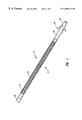
- FIG. 1 is a perspective view showing the distal end section of the lead of the present invention.
- FIG. 2 cross-sectional view of the distal section of the lead shown in FIG. 1 .
- FIG. 3 is a cross-sectional view of the proximal section of the lead shown in FIG. 1 .
- FIG. 4 is a perspective view of the distal section of a second embodiment of the present invention.
- FIG. 5 is a cross-sectional view of the distal section of the embodiment shown in FIG. 4 .
- FIG. 6 is a cross-sectional view of the proximal section of the embodiment shown in FIG. 4 .
- FIG. 7 is a side view showing a first electrode design.
- FIG. 8 is a side view showing a second electrode design.
- FIG. 9 is a side view showing a third electrode design.
- FIG. 10 is a side view of a self-sealing disk used to seal a lumen of the lead.
- FIG. 11 is an end view of the self-sealing disk shown in FIG. 10 .
- FIGS. 12-16 are each cross-sectional views showing alternative multi-lumen lead designs.
- FIG. 17 shows a first embodiment of a dual in-line connector.
- FIG. 18 shows a second embodiment of a dual in-line connector.
- FIGS. 1-3 A first embodiment of the invention is shown generally in FIGS. 1-3.
- the lead 10 includes a distal section 12 shown in FIGS. 1 and 2 and a proximal section 14 shown in FIG. 3 .
- the distal section 12 includes a coil-shaped electrode 16 .
- the electrode 16 can be made of a single wire. However, multi-filar wire coil is preferred.
- the coil-shaped electrode 16 surrounds a silicone tubing 18 .
- the coil-shaped electrode 16 is also electrically coupled to a conductive coil 20 which is used to carry pulses between the electrode 16 and a terminal pin 22 .
- the coil-shaped electrode 16 is preferably a winding of multiple wires coupled together. This also serves to significantly reduce electrical resistance.
- Suitable wire materials include platinum clad titanium, platinum clad tantalum, or platinum coated MP 35 N wire.
- the conductive coil 20 preferably has a biased area that can be used to help retain the lead in the desired position in the vein.
- the terminal pin 22 is used to couple the lead 10 to a cardiac rhythm management device such as an implantable defibrillator.
- the terminal pin 22 is preferably removable and/or small enough to permit the walls of a lumen of a guide catheter to pass over pin 22 .
- FIGS. 1-3 show other important features of the invention.
- an insulative layer 24 surrounds the conductive coil 20 .
- Suitable materials for the insulative layer 24 include silicone, polytetrafluoroethylene (PTFE) and polyurethane. Silicone offers the advantages of being very flexible and soft. PTFE offers the advantages of being thin, durable, and reduces abrasion. Polyurethane is stiffer than silicone, but smoother and more durable.
- the insulative layer 24 may include a combination of these materials. For example, the majority of the insulative layer might be silicone.
- a layer of PTFE might be placed between the coil 20 and the silicone on approximately two-thirds the length of the lead 10 to stiffen the proximal section to facilitate advancing the lead 10 over a guidewire during insertion of the lead.
- Polyurethane might be used as an outer layer over the silicone to prevent abrasion of the vessel wall as the lead is implanted a coating of a lubricious material may also be provided.
- the proximal end section will be stiffer than the distal section so that the proximal section has sufficient axial stiffness to allow the lead to be advanced and the distal section is sufficiently flexible to be routed along the desired path and at the same time be sufficiently atraumatic.
- FIGS. 1 and 2 show that the distal section 12 terminates with an atraumatic tip 26 at the distal end.
- the tip 26 is designed to completely cover the electrically conductive coil 20 to prevent vessel erosion.
- the tip 26 also acts to dilate the venous structure to facilitate implantation of the lead 10 .
- Suitable materials for the tip 26 include silicone or other soft, pliable polymers.
- FIGS. 1 and 2 also show a fixation device 28 incorporating a plurality of tines 30 .
- These tines 30 are preferably deployable and act to increase the mechanical pressure against the vessel wall to hold the lead 10 in place.
- Suitable materials include silicone and polyurethane.
- the lead could be microtextured to permit fibrotic attachment to the wall of the coronary vein.
- the tines could also be made detachable or absorbable in the event the lead needs to be explanted. Materials could include poliglecaprone 25, polyglactin 910 or polydioxanone.
- FIGS. 4-6 show an alternative embodiment of the present invention.
- This embodiment incorporates a plurality of small ring electrodes 40 in place of the wire coil electrode 16 .
- a soft, flexible, insulative material covers the conductive coil 20 between the ring electrodes.
- the conductive coil 20 carries current from the terminal pin 22 to each ring electrode.
- a plurality of cables could be used in place of the coil 20 if it is desired to have the ring electrodes 40 perform separate functions, i.e., pacing, defibrillating or sensing.
- FIGS. 7-9 show various alternative electrode designs.
- the electrode 40 comprises silicone rubber doped with conductive particles.
- the electrode 40 merely comprises an exposed section of the conductive coil 20 .
- the electrode 40 is a conductive braided wire screen electrically coupled to the conductive coil 20 .
- a standard ring electrode might also be used, but it would be less flexible than the electrode arrangements shown in FIGS. 7-9.
- a significant feature of the present invention is a deployable plug comprising the sealing disk 50 shown in FIGS. 10 and 11.
- This disk 50 is deployable so that it resides in the lumen 17 of the lead 10 to block the unintended passage of fluids through the lumen.
- the disk 50 is made of a low durometer silicone and has an orifice 52 that extends through it.
- the orifice 52 is sized to allow a guidewire to pass through it. However, when the guidewire is removed, the orifice seals behind it.
- the disk 50 could have a self-sealing flap or made of a hydrophilic material designed to expand when subjected to moisture to seal the lumen.
- FIGS. 12-16 show separate multi-lumen designs fully within the scope of the invention.
- FIG. 12 shows a pair of concentric lumens 60 and 62 .
- Lumen 60 is designed to accommodate a guidewire.
- a conductive cable resides in lumen 62 .
- FIG. 13 shows a pair of concentric lumens 60 and 62 and a third lumen 64 that functions as a guide tube.
- FIGS. 14 and 15 show a design that includes a first lumen 70 through which a cable conductor 71 passes and a lumen 72 to accommodate a guidewire, injection of fluoroscopic dye or the like.
- FIG. 16 shows an arrangement incorporating a larger central lumen 80 and smaller top and bottom lumens 82 and 84 .
- the top lumen 82 can each include a braided cable 71 which replaces the conductive coil.
- the larger central lumen 80 can accommodate a guidewire.
- This lumen may be coated with a lubricious material so that the lead slides easily with respect to a guide wire used during implantation of the lead.
- the outer wall of the lead body can also be coated with a lubricious material to reduce friction between the lead and vessel wall.
- the bottom lumen can be used for dye injection or for another braided cable if the lead includes multiple electrodes used for differing purposes.
- two terminal pins 22 or a dual in-line connector will be required.
- the first cable can be coupled to an electrode for delivery of defibrillating pulses.
- the second cable can be coupled to a second electrode for delivering pacing pulses to the heart or to sense the electrical activity of the heart.
- a dual in-line connector 90 of the types shown in either FIGS. 17 and 18 could be used.
- Each dual in-line connector has a first conductive element 92 and a second conductive element 94 . In FIG. 17, the first and second conductive elements are spaced apart bands electrically insulated from each other.
- Each band is electrically coupled to a separate electrode by a wire or the like.
- the electrically conductive elements are a pair of coaxial wire coils, one having a smaller diameter than the other.
- other multiple arrangements can be used without deviating from the invention.
Abstract
Description
Claims (13)
Priority Applications (5)
| Application Number | Priority Date | Filing Date | Title |
|---|---|---|---|
| US09/407,364 US6408213B1 (en) | 1999-09-29 | 1999-09-29 | Low profile, ventricular, transvenous, epicardial defibrillation lead |
| AU70695/00A AU7069500A (en) | 1999-09-29 | 2000-08-24 | Low profile, ventricular, transvenous, epicardial defibrillation lead |
| EP00959359A EP1133332A1 (en) | 1999-09-29 | 2000-08-24 | Low profile, ventricular, transvenous, epicardial defibrillation lead |
| PCT/US2000/023273 WO2001023033A1 (en) | 1999-09-29 | 2000-08-24 | Low profile, ventricular, transvenous, epicardial defibrillation lead |
| US10/117,483 US20020111664A1 (en) | 1999-09-29 | 2002-04-05 | Low profile, ventricular, transvenous, epicardial defibrillation lead |
Applications Claiming Priority (1)
| Application Number | Priority Date | Filing Date | Title |
|---|---|---|---|
| US09/407,364 US6408213B1 (en) | 1999-09-29 | 1999-09-29 | Low profile, ventricular, transvenous, epicardial defibrillation lead |
Related Child Applications (1)
| Application Number | Title | Priority Date | Filing Date |
|---|---|---|---|
| US10/117,483 Division US20020111664A1 (en) | 1999-09-29 | 2002-04-05 | Low profile, ventricular, transvenous, epicardial defibrillation lead |
Publications (1)
| Publication Number | Publication Date |
|---|---|
| US6408213B1 true US6408213B1 (en) | 2002-06-18 |
Family
ID=23611734
Family Applications (2)
| Application Number | Title | Priority Date | Filing Date |
|---|---|---|---|
| US09/407,364 Expired - Lifetime US6408213B1 (en) | 1999-09-29 | 1999-09-29 | Low profile, ventricular, transvenous, epicardial defibrillation lead |
| US10/117,483 Abandoned US20020111664A1 (en) | 1999-09-29 | 2002-04-05 | Low profile, ventricular, transvenous, epicardial defibrillation lead |
Family Applications After (1)
| Application Number | Title | Priority Date | Filing Date |
|---|---|---|---|
| US10/117,483 Abandoned US20020111664A1 (en) | 1999-09-29 | 2002-04-05 | Low profile, ventricular, transvenous, epicardial defibrillation lead |
Country Status (4)
| Country | Link |
|---|---|
| US (2) | US6408213B1 (en) |
| EP (1) | EP1133332A1 (en) |
| AU (1) | AU7069500A (en) |
| WO (1) | WO2001023033A1 (en) |
Cited By (21)
| Publication number | Priority date | Publication date | Assignee | Title |
|---|---|---|---|---|
| US20020072737A1 (en) * | 2000-12-08 | 2002-06-13 | Medtronic, Inc. | System and method for placing a medical electrical lead |
| US20030083725A1 (en) * | 2001-10-29 | 2003-05-01 | Berthold Kramm | Method and apparatus for endovenous pacing lead |
| US20030181966A1 (en) * | 2002-03-19 | 2003-09-25 | Morgan Kevin L. | Leads using composite materials for conductors and stylet insertion for improved handling characteristics in lead implantation performance |
| US20030220677A1 (en) * | 2002-05-22 | 2003-11-27 | Doan Phong D. | Implantable coronary sinus lead and lead system |
| US6671560B2 (en) * | 1998-06-12 | 2003-12-30 | Cardiac Pacemakers, Inc. | Modified guidewire for left ventricular access lead |
| WO2004060478A1 (en) * | 2002-12-16 | 2004-07-22 | Medtronic, Inc. | A catheter-delivered cardiac lead |
| US20050004560A1 (en) * | 2001-06-20 | 2005-01-06 | Microvention, Inc. | Medical devices having full or partial polymer coatings and their methods of manufacture |
| US20050085885A1 (en) * | 1998-08-12 | 2005-04-21 | Cardiac Pacemakers, Inc. | Expandable seal for use with medical device and system |
| US20050234534A1 (en) * | 2002-04-22 | 2005-10-20 | Pardo Xavier E | Implantable lead with improved conductor lumens |
| EP1595571A1 (en) * | 2004-05-14 | 2005-11-16 | Biotronik GmbH & Co. KG | Electrode lead |
| US20060161238A1 (en) * | 2004-08-03 | 2006-07-20 | Hall Jeffrey A | Thoracoscopic epicardial cardiac lead with guiding deployment applicator and method therefor |
| US20060206154A1 (en) * | 2005-03-11 | 2006-09-14 | Julia Moffitt | Combined neural stimulation and cardiac resynchronization therapy |
| US7212871B1 (en) * | 2003-12-24 | 2007-05-01 | Pacesetter, Inc. | Epicardial and myocardial leads for implanting in the heart by thoracotomy or port access surgeries with detachable electrode tip |
| US20070123923A1 (en) * | 2005-11-30 | 2007-05-31 | Lindstrom Curtis C | Implantable medical device minimizing rotation and dislocation |
| US20070293922A1 (en) * | 2006-06-15 | 2007-12-20 | Cardiac Pacemakers, Inc. | Medical electrical lead with friction-enhancing fixation features |
| US20080086174A1 (en) * | 2006-10-04 | 2008-04-10 | Cardiac Pacemakers, Inc. | System for neurally-mediated anti-arrhythmic therapy |
| US20080294228A1 (en) * | 2007-05-23 | 2008-11-27 | Cardiac Pacemakers | Method and device for controlled stimulation of lymphatic flow |
| US7657324B2 (en) | 1998-08-12 | 2010-02-02 | Cardiac Pacemakers, Inc. | Seal for use with cardiac lead |
| US20110071608A1 (en) * | 2009-09-23 | 2011-03-24 | Lake Region Manufacturing, Inc. d/b/a Lake Region Medical | Guidewire-style pacing lead |
| US8369943B2 (en) | 2006-06-06 | 2013-02-05 | Cardiac Pacemakers, Inc. | Method and apparatus for neural stimulation via the lymphatic system |
| US10350094B2 (en) | 2013-03-11 | 2019-07-16 | Microvention, Inc. | Implantable device with adhesive properties |
Families Citing this family (29)
| Publication number | Priority date | Publication date | Assignee | Title |
|---|---|---|---|---|
| ATE424695T1 (en) * | 2001-09-13 | 2009-03-15 | Med El Elektromed Geraete Gmbh | INNER EAR ELECTRODE WITH PARTIALLY REMOVABLE HYDROPHILE SEGMENT FOR LATER SELF-POSITIONING |
| US6999821B2 (en) * | 2002-01-18 | 2006-02-14 | Pacesetter, Inc. | Body implantable lead including one or more conductive polymer electrodes and methods for fabricating same |
| US7031777B2 (en) * | 2002-09-27 | 2006-04-18 | Medtronic, Inc. | Cardiac vein lead with flexible anode and method for forming same |
| US7231259B2 (en) * | 2002-10-04 | 2007-06-12 | Pacesetter, Inc. | Body implantable lead comprising electrically conductive polymer conductors |
| WO2004056297A1 (en) * | 2002-12-19 | 2004-07-08 | Cochlear Limited | Method and apparatus for sealing a lumen in an electrode assembly |
| US7610101B2 (en) * | 2006-11-30 | 2009-10-27 | Cardiac Pacemakers, Inc. | RF rejecting lead |
| US8731685B2 (en) * | 2007-12-06 | 2014-05-20 | Cardiac Pacemakers, Inc. | Implantable lead having a variable coil conductor pitch |
| US20090312769A1 (en) * | 2007-12-10 | 2009-12-17 | Cochlear Limited | Stylet for stimulating medical implants |
| JP5149399B2 (en) | 2008-02-06 | 2013-02-20 | カーディアック ペースメイカーズ, インコーポレイテッド | Lead with design features compatible with MRI |
| US8103360B2 (en) | 2008-05-09 | 2012-01-24 | Foster Arthur J | Medical lead coil conductor with spacer element |
| US7904177B2 (en) * | 2008-06-25 | 2011-03-08 | Cardiac Pacemakers, Inc. | Lead interconnect using a capured fixation member |
| WO2010104643A2 (en) | 2009-03-12 | 2010-09-16 | Cardiac Pacemakers, Inc. | Thin profile conductor assembly for medical device leads |
| JP5542926B2 (en) | 2009-06-26 | 2014-07-09 | カーディアック ペースメイカーズ, インコーポレイテッド | Medical instrument lead comprising a conductor assembly consisting of a single wire coil with improved torque transfer performance and reduced heating by MRI |
| US8335572B2 (en) * | 2009-10-08 | 2012-12-18 | Cardiac Pacemakers, Inc. | Medical device lead including a flared conductive coil |
| US9254380B2 (en) | 2009-10-19 | 2016-02-09 | Cardiac Pacemakers, Inc. | MRI compatible tachycardia lead |
| US20110137393A1 (en) * | 2009-12-03 | 2011-06-09 | Pawsey Nicholas C | Stiffiner having an enlarged bombous distal end region and corresponding cochlear implant stimulating assembly |
| JP5551794B2 (en) * | 2009-12-30 | 2014-07-16 | カーディアック ペースメイカーズ, インコーポレイテッド | Medical device leads safe under MRI conditions |
| US8391994B2 (en) * | 2009-12-31 | 2013-03-05 | Cardiac Pacemakers, Inc. | MRI conditionally safe lead with low-profile multi-layer conductor for longitudinal expansion |
| EP2519305B1 (en) * | 2009-12-31 | 2017-07-05 | Cardiac Pacemakers, Inc. | Mri conditionally safe lead with multi-layer conductor |
| US8825181B2 (en) | 2010-08-30 | 2014-09-02 | Cardiac Pacemakers, Inc. | Lead conductor with pitch and torque control for MRI conditionally safe use |
| AU2012333113B2 (en) | 2011-11-04 | 2014-11-20 | Cardiac Pacemakers, Inc. | Implantable medical device lead including inner coil reverse-wound relative to shocking coil |
| US8825179B2 (en) | 2012-04-20 | 2014-09-02 | Cardiac Pacemakers, Inc. | Implantable medical device lead including a unifilar coiled cable |
| US8954168B2 (en) | 2012-06-01 | 2015-02-10 | Cardiac Pacemakers, Inc. | Implantable device lead including a distal electrode assembly with a coiled component |
| US8958889B2 (en) | 2012-08-31 | 2015-02-17 | Cardiac Pacemakers, Inc. | MRI compatible lead coil |
| US9044589B2 (en) * | 2012-09-11 | 2015-06-02 | Cochlear Limited | Electrode constructions and methods for making the same |
| CN104736196B (en) | 2012-10-18 | 2017-06-16 | 心脏起搏器股份公司 | Sensing element for providing Magnetic resonance imaging compatibility in implantable medical device lead |
| EP3110499B1 (en) | 2014-02-26 | 2018-01-24 | Cardiac Pacemakers, Inc. | Construction of an mri-safe tachycardia lead |
| US11612740B2 (en) | 2017-11-20 | 2023-03-28 | Cochlear Limited | Electrode array manufacture |
| EP3826712B1 (en) * | 2018-07-23 | 2024-02-28 | Cardiac Pacemakers, Inc. | Retention mechanism for an implantable lead |
Citations (14)
| Publication number | Priority date | Publication date | Assignee | Title |
|---|---|---|---|---|
| US3974834A (en) * | 1975-04-23 | 1976-08-17 | Medtronic, Inc. | Body-implantable lead |
| EP0653223A2 (en) | 1993-11-02 | 1995-05-17 | Incontrol, Inc. | An improved implantable lead having a steering distal guide tip |
| US5545206A (en) * | 1994-12-22 | 1996-08-13 | Ventritex, Inc. | Low profile lead with automatic tine activation |
| US5755766A (en) * | 1997-01-24 | 1998-05-26 | Cardiac Pacemakers, Inc. | Open-ended intravenous cardiac lead |
| US5759202A (en) * | 1997-04-28 | 1998-06-02 | Sulzer Intermedics Inc. | Endocardial lead with lateral active fixation |
| US5800495A (en) | 1997-03-27 | 1998-09-01 | Sulzer Intermedics Inc. | Endocardial lead assembly |
| US5800497A (en) * | 1997-07-17 | 1998-09-01 | Medtronic, Inc. | Medical electrical lead with temporarily stiff portion |
| US5803928A (en) * | 1997-01-24 | 1998-09-08 | Cardiac Pacemakers, Inc. | Side access "over the wire" pacing lead |
| US5931864A (en) * | 1998-02-20 | 1999-08-03 | Cardiac Pacemakers, Inc. | Coronary venous lead having fixation mechanism |
| WO1999055412A1 (en) | 1998-04-29 | 1999-11-04 | Emory University | Cardiac pacing lead and delivery system |
| US6001085A (en) * | 1993-08-13 | 1999-12-14 | Daig Corporation | Coronary sinus catheter |
| US6070104A (en) * | 1997-11-28 | 2000-05-30 | Medtronic, Inc. | Medical electrical right atrium and coronary sinus lead |
| US6122552A (en) * | 1999-03-03 | 2000-09-19 | Cardiac Pacemakers, Inc. | Insertion apparatus for left ventricular access lead |
| US6240321B1 (en) * | 1998-08-12 | 2001-05-29 | Cardiac Pacemakers, Inc. | Expandable seal for use with medical device and system |
Family Cites Families (22)
| Publication number | Priority date | Publication date | Assignee | Title |
|---|---|---|---|---|
| US3815611A (en) * | 1971-11-26 | 1974-06-11 | Medtronic Inc | Muscle stimulation and/or contraction detection device |
| US4662382A (en) * | 1985-01-16 | 1987-05-05 | Intermedics, Inc. | Pacemaker lead with enhanced sensitivity |
| US4662377A (en) * | 1985-11-07 | 1987-05-05 | Mieczyslaw Mirowski | Cardioverting method and apparatus utilizing catheter and patch electrodes |
| US5014696A (en) * | 1987-01-14 | 1991-05-14 | Medtronic, Inc. | Endocardial defibrillation electrode system |
| US4932407A (en) * | 1988-12-15 | 1990-06-12 | Medtronic, Inc. | Endocardial defibrillation electrode system |
| US5411527A (en) * | 1989-05-03 | 1995-05-02 | Intermedics, Inc. | Difibrillation electrodes and implantation |
| US5005587A (en) * | 1989-11-13 | 1991-04-09 | Pacing Systems, Inc. | Braid Electrode leads and catheters and methods for using the same |
| US5433729A (en) * | 1991-04-12 | 1995-07-18 | Incontrol, Inc. | Atrial defibrillator, lead systems, and method |
| US5348021A (en) * | 1992-03-31 | 1994-09-20 | Incontrol, Inc. | Apparatus and method for reliably detecting a depolarization activation wave of the heart and atrial defibrillator utilizing same |
| SE9203735D0 (en) * | 1992-12-11 | 1992-12-11 | Siemens Elema Ab | ELECTRIC SYSTEM FOR DEFIBRILLATOR |
| SE9203732D0 (en) * | 1992-12-11 | 1992-12-11 | Siemens Elema Ab | ELECTRIC SYSTEM FOR DEFIBRILLATOR |
| IT1271458B (en) * | 1993-03-08 | 1997-05-28 | Leonardo Cammilli | SEQUENTIAL CARDIAC STIMULATION (DDD) SYSTEM WITH THE USE OF A SINGLE LEAD INSERTED THROUGH THE CORONARY BREAST. |
| US5385579A (en) * | 1993-03-30 | 1995-01-31 | Siemens Pacesetter, Inc. | Myocardial body implantable lead |
| US5423772A (en) * | 1993-08-13 | 1995-06-13 | Daig Corporation | Coronary sinus catheter |
| US5458621A (en) * | 1994-03-15 | 1995-10-17 | Incontrol, Inc. | Automatic gain control and method for enabling detection of low and high amplitude depolarization activation waves of the heart and atrial defibrillator utilizing the same |
| US5681514A (en) * | 1995-06-07 | 1997-10-28 | Sulzer Intermedics Inc. | Method for making an implantable conductive lead for use with a cardiac stimulator |
| US5935160A (en) * | 1997-01-24 | 1999-08-10 | Cardiac Pacemakers, Inc. | Left ventricular access lead for heart failure pacing |
| US5922014A (en) * | 1997-09-02 | 1999-07-13 | Medtronic, Inc. | Single pass lead and method of use |
| US5919222A (en) * | 1998-01-06 | 1999-07-06 | Medtronic Inc. | Adjustable medical electrode lead |
| US6321123B1 (en) * | 1999-03-08 | 2001-11-20 | Medtronic Inc. | J-shaped coronary sinus lead |
| US6192280B1 (en) * | 1999-06-02 | 2001-02-20 | Medtronic, Inc. | Guidewire placed implantable lead with tip seal |
| US6377856B1 (en) * | 1999-06-14 | 2002-04-23 | Pacesetter, Inc. | Device and method for implanting medical leads |
-
1999
- 1999-09-29 US US09/407,364 patent/US6408213B1/en not_active Expired - Lifetime
-
2000
- 2000-08-24 WO PCT/US2000/023273 patent/WO2001023033A1/en not_active Application Discontinuation
- 2000-08-24 AU AU70695/00A patent/AU7069500A/en not_active Abandoned
- 2000-08-24 EP EP00959359A patent/EP1133332A1/en not_active Withdrawn
-
2002
- 2002-04-05 US US10/117,483 patent/US20020111664A1/en not_active Abandoned
Patent Citations (14)
| Publication number | Priority date | Publication date | Assignee | Title |
|---|---|---|---|---|
| US3974834A (en) * | 1975-04-23 | 1976-08-17 | Medtronic, Inc. | Body-implantable lead |
| US6001085A (en) * | 1993-08-13 | 1999-12-14 | Daig Corporation | Coronary sinus catheter |
| EP0653223A2 (en) | 1993-11-02 | 1995-05-17 | Incontrol, Inc. | An improved implantable lead having a steering distal guide tip |
| US5545206A (en) * | 1994-12-22 | 1996-08-13 | Ventritex, Inc. | Low profile lead with automatic tine activation |
| US5755766A (en) * | 1997-01-24 | 1998-05-26 | Cardiac Pacemakers, Inc. | Open-ended intravenous cardiac lead |
| US5803928A (en) * | 1997-01-24 | 1998-09-08 | Cardiac Pacemakers, Inc. | Side access "over the wire" pacing lead |
| US5800495A (en) | 1997-03-27 | 1998-09-01 | Sulzer Intermedics Inc. | Endocardial lead assembly |
| US5759202A (en) * | 1997-04-28 | 1998-06-02 | Sulzer Intermedics Inc. | Endocardial lead with lateral active fixation |
| US5800497A (en) * | 1997-07-17 | 1998-09-01 | Medtronic, Inc. | Medical electrical lead with temporarily stiff portion |
| US6070104A (en) * | 1997-11-28 | 2000-05-30 | Medtronic, Inc. | Medical electrical right atrium and coronary sinus lead |
| US5931864A (en) * | 1998-02-20 | 1999-08-03 | Cardiac Pacemakers, Inc. | Coronary venous lead having fixation mechanism |
| WO1999055412A1 (en) | 1998-04-29 | 1999-11-04 | Emory University | Cardiac pacing lead and delivery system |
| US6240321B1 (en) * | 1998-08-12 | 2001-05-29 | Cardiac Pacemakers, Inc. | Expandable seal for use with medical device and system |
| US6122552A (en) * | 1999-03-03 | 2000-09-19 | Cardiac Pacemakers, Inc. | Insertion apparatus for left ventricular access lead |
Cited By (45)
| Publication number | Priority date | Publication date | Assignee | Title |
|---|---|---|---|---|
| US6671560B2 (en) * | 1998-06-12 | 2003-12-30 | Cardiac Pacemakers, Inc. | Modified guidewire for left ventricular access lead |
| US20050085885A1 (en) * | 1998-08-12 | 2005-04-21 | Cardiac Pacemakers, Inc. | Expandable seal for use with medical device and system |
| US7657324B2 (en) | 1998-08-12 | 2010-02-02 | Cardiac Pacemakers, Inc. | Seal for use with cardiac lead |
| US7412290B2 (en) | 1998-08-12 | 2008-08-12 | Cardiac Pacemakers, Inc. | Seal for use with medical device and system |
| US6901288B2 (en) | 1998-08-12 | 2005-05-31 | Cardiac Pacemakers, Inc. | Sealing assembly for intravenous lead |
| US20020072737A1 (en) * | 2000-12-08 | 2002-06-13 | Medtronic, Inc. | System and method for placing a medical electrical lead |
| US20050004560A1 (en) * | 2001-06-20 | 2005-01-06 | Microvention, Inc. | Medical devices having full or partial polymer coatings and their methods of manufacture |
| US7494687B2 (en) * | 2001-06-20 | 2009-02-24 | Microvention, Inc. | Medical devices having full or partial polymer coatings and their methods of manufacture |
| US7657323B2 (en) | 2001-10-29 | 2010-02-02 | Medtronic, Inc. | Endovenous device for dispersing a dilating agent |
| US6936040B2 (en) * | 2001-10-29 | 2005-08-30 | Medtronic, Inc. | Method and apparatus for endovenous pacing lead |
| US20050256559A1 (en) * | 2001-10-29 | 2005-11-17 | Medtronic, Inc. | Method and apparatus for endovenous pacing lead |
| US20030083725A1 (en) * | 2001-10-29 | 2003-05-01 | Berthold Kramm | Method and apparatus for endovenous pacing lead |
| US6973351B2 (en) | 2002-03-19 | 2005-12-06 | Pacesetter, Inc. | Leads using composite materials for conductors and stylet insertion for improved handling characteristics in lead implantation performance |
| US20030181966A1 (en) * | 2002-03-19 | 2003-09-25 | Morgan Kevin L. | Leads using composite materials for conductors and stylet insertion for improved handling characteristics in lead implantation performance |
| US20050234534A1 (en) * | 2002-04-22 | 2005-10-20 | Pardo Xavier E | Implantable lead with improved conductor lumens |
| US7818070B2 (en) | 2002-04-22 | 2010-10-19 | Medtronic, Inc. | Method of manufacturing an implantable lead |
| US20100306997A1 (en) * | 2002-04-22 | 2010-12-09 | Medtronic, Inc. | Method of manufacturing an implantable lead |
| US7310873B2 (en) * | 2002-04-22 | 2007-12-25 | Medtronic, Inc. | Method of manufacturing an implantable lead |
| US6968237B2 (en) * | 2002-05-22 | 2005-11-22 | Pacesetter, Inc. | Implantable coronary sinus lead and lead system |
| US20030220677A1 (en) * | 2002-05-22 | 2003-11-27 | Doan Phong D. | Implantable coronary sinus lead and lead system |
| US7184839B2 (en) | 2002-12-16 | 2007-02-27 | Medtronic, Inc. | Catheter-delivered cardiac lead |
| WO2004060478A1 (en) * | 2002-12-16 | 2004-07-22 | Medtronic, Inc. | A catheter-delivered cardiac lead |
| US7212871B1 (en) * | 2003-12-24 | 2007-05-01 | Pacesetter, Inc. | Epicardial and myocardial leads for implanting in the heart by thoracotomy or port access surgeries with detachable electrode tip |
| EP1595571A1 (en) * | 2004-05-14 | 2005-11-16 | Biotronik GmbH & Co. KG | Electrode lead |
| US7493173B2 (en) | 2004-05-14 | 2009-02-17 | Biotronik Crm Patent Ag | Electrode line |
| US20050256558A1 (en) * | 2004-05-14 | 2005-11-17 | Biotronik Gmbh & Co. Kg | Electrode line |
| US20060161238A1 (en) * | 2004-08-03 | 2006-07-20 | Hall Jeffrey A | Thoracoscopic epicardial cardiac lead with guiding deployment applicator and method therefor |
| US7587238B2 (en) | 2005-03-11 | 2009-09-08 | Cardiac Pacemakers, Inc. | Combined neural stimulation and cardiac resynchronization therapy |
| US20060206154A1 (en) * | 2005-03-11 | 2006-09-14 | Julia Moffitt | Combined neural stimulation and cardiac resynchronization therapy |
| US8131362B2 (en) | 2005-03-11 | 2012-03-06 | Cardiac Pacemakers, Inc. | Combined neural stimulation and cardiac resynchronization therapy |
| US20090306734A1 (en) * | 2005-03-11 | 2009-12-10 | Julia Moffitt | Combined neural stimulation and cardiac resynchronization therapy |
| US20070123923A1 (en) * | 2005-11-30 | 2007-05-31 | Lindstrom Curtis C | Implantable medical device minimizing rotation and dislocation |
| US8369943B2 (en) | 2006-06-06 | 2013-02-05 | Cardiac Pacemakers, Inc. | Method and apparatus for neural stimulation via the lymphatic system |
| US7725197B2 (en) | 2006-06-15 | 2010-05-25 | Cardiac Pacemakers, Inc. | Medical electrical lead with friction-enhancing fixation features |
| US20070293922A1 (en) * | 2006-06-15 | 2007-12-20 | Cardiac Pacemakers, Inc. | Medical electrical lead with friction-enhancing fixation features |
| US20080086174A1 (en) * | 2006-10-04 | 2008-04-10 | Cardiac Pacemakers, Inc. | System for neurally-mediated anti-arrhythmic therapy |
| US20080086175A1 (en) * | 2006-10-04 | 2008-04-10 | Cardiac Pacemakers, Inc | Method and apparatus for reducing defibrillation threshold |
| US8983598B2 (en) | 2006-10-04 | 2015-03-17 | Cardiac Pacemakers, Inc. | System for neurally-mediated anti-arrhythmic therapy |
| US20080294228A1 (en) * | 2007-05-23 | 2008-11-27 | Cardiac Pacemakers | Method and device for controlled stimulation of lymphatic flow |
| US20110071608A1 (en) * | 2009-09-23 | 2011-03-24 | Lake Region Manufacturing, Inc. d/b/a Lake Region Medical | Guidewire-style pacing lead |
| WO2011037978A3 (en) * | 2009-09-23 | 2011-09-09 | Lake Region Manufacturing, Inc.D/B/A/ Lake Regional Medical | Guidewire-style pacing lead |
| CN102711902A (en) * | 2009-09-23 | 2012-10-03 | 湖区制造公司,商用名湖区医药 | Guidewire-style pacing lead |
| CN102711902B (en) * | 2009-09-23 | 2015-09-16 | 湖区制造公司,商用名湖区医药 | Seal wire type pacing lead |
| US9387323B2 (en) | 2009-09-23 | 2016-07-12 | Lake Region Manufacturing, Inc. | Guidewire-style pacing lead |
| US10350094B2 (en) | 2013-03-11 | 2019-07-16 | Microvention, Inc. | Implantable device with adhesive properties |
Also Published As
| Publication number | Publication date |
|---|---|
| EP1133332A1 (en) | 2001-09-19 |
| AU7069500A (en) | 2001-04-30 |
| US20020111664A1 (en) | 2002-08-15 |
| WO2001023033A1 (en) | 2001-04-05 |
Similar Documents
| Publication | Publication Date | Title |
|---|---|---|
| US6408213B1 (en) | Low profile, ventricular, transvenous, epicardial defibrillation lead | |
| US6129749A (en) | Monorail left ventricular access lead | |
| EP0954352B1 (en) | Cardiac lead arrangement | |
| EP0954240B1 (en) | Side access "over the wire" pacing lead | |
| US7860580B2 (en) | Active fixation medical electrical lead | |
| EP2092955B1 (en) | Leads for pacing and/or sensing the heart from within the coronary veins | |
| US7711437B1 (en) | Lead fixation device | |
| US8046084B2 (en) | Extendable/retractable lead having downsized lead body | |
| US4360031A (en) | Drug dispensing irrigatable electrode | |
| US7657324B2 (en) | Seal for use with cardiac lead | |
| US7229450B1 (en) | Kink resistant introducer with mapping capabilities | |
| US5800495A (en) | Endocardial lead assembly | |
| US5755765A (en) | Pacing lead having detachable positioning member | |
| US20090259283A1 (en) | Sheathed lead for pacing or defibrillation | |
| US20050080471A1 (en) | Lead body construction | |
| US5827296A (en) | Medical electrical lead | |
| US20030181966A1 (en) | Leads using composite materials for conductors and stylet insertion for improved handling characteristics in lead implantation performance | |
| US6647291B1 (en) | Method and apparatus for cardiac defibrillation | |
| EP0959940B1 (en) | Lead introducer with defibrillation electrode for atrial defibrillation | |
| US7890190B1 (en) | Deflectable hollow stylet guidewire system |
Legal Events
| Date | Code | Title | Description |
|---|---|---|---|
| AS | Assignment |
Owner name: CARDIAC PACEMAKERS, INC., MINNESOTA Free format text: ASSIGNMENT OF ASSIGNORS INTEREST;ASSIGNORS:BARTIG, JEFFREY T.;CHASTAIN, STUART R.;CREVENSTEN, GWEN;AND OTHERS;REEL/FRAME:010297/0502 Effective date: 19990921 Owner name: CARDIAC PACEMAKERS, INC., MINNESOTA Free format text: ASSIGNMENT OF ASSIGNORS INTEREST;ASSIGNOR:JANKE, AARON W.;REEL/FRAME:010297/0508 Effective date: 19990924 |
|
| STCF | Information on status: patent grant |
Free format text: PATENTED CASE |
|
| CC | Certificate of correction | ||
| FEPP | Fee payment procedure |
Free format text: PAYOR NUMBER ASSIGNED (ORIGINAL EVENT CODE: ASPN); ENTITY STATUS OF PATENT OWNER: LARGE ENTITY |
|
| FPAY | Fee payment |
Year of fee payment: 4 |
|
| FEPP | Fee payment procedure |
Free format text: PAYER NUMBER DE-ASSIGNED (ORIGINAL EVENT CODE: RMPN); ENTITY STATUS OF PATENT OWNER: LARGE ENTITY Free format text: PAYOR NUMBER ASSIGNED (ORIGINAL EVENT CODE: ASPN); ENTITY STATUS OF PATENT OWNER: LARGE ENTITY |
|
| FPAY | Fee payment |
Year of fee payment: 8 |
|
| FPAY | Fee payment |
Year of fee payment: 12 |