US6456339B1 - Super-resolution display - Google Patents
Super-resolution display Download PDFInfo
- Publication number
- US6456339B1 US6456339B1 US09/181,320 US18132098A US6456339B1 US 6456339 B1 US6456339 B1 US 6456339B1 US 18132098 A US18132098 A US 18132098A US 6456339 B1 US6456339 B1 US 6456339B1
- Authority
- US
- United States
- Prior art keywords
- projector
- pixel
- correction function
- sensor
- frame buffer
- Prior art date
- Legal status (The legal status is an assumption and is not a legal conclusion. Google has not performed a legal analysis and makes no representation as to the accuracy of the status listed.)
- Expired - Lifetime
Links
Images


Classifications
-
- G—PHYSICS
- G03—PHOTOGRAPHY; CINEMATOGRAPHY; ANALOGOUS TECHNIQUES USING WAVES OTHER THAN OPTICAL WAVES; ELECTROGRAPHY; HOLOGRAPHY
- G03B—APPARATUS OR ARRANGEMENTS FOR TAKING PHOTOGRAPHS OR FOR PROJECTING OR VIEWING THEM; APPARATUS OR ARRANGEMENTS EMPLOYING ANALOGOUS TECHNIQUES USING WAVES OTHER THAN OPTICAL WAVES; ACCESSORIES THEREFOR
- G03B37/00—Panoramic or wide-screen photography; Photographing extended surfaces, e.g. for surveying; Photographing internal surfaces, e.g. of pipe
- G03B37/04—Panoramic or wide-screen photography; Photographing extended surfaces, e.g. for surveying; Photographing internal surfaces, e.g. of pipe with cameras or projectors providing touching or overlapping fields of view
-
- H—ELECTRICITY
- H04—ELECTRIC COMMUNICATION TECHNIQUE
- H04N—PICTORIAL COMMUNICATION, e.g. TELEVISION
- H04N9/00—Details of colour television systems
- H04N9/12—Picture reproducers
-
- H—ELECTRICITY
- H04—ELECTRIC COMMUNICATION TECHNIQUE
- H04N—PICTORIAL COMMUNICATION, e.g. TELEVISION
- H04N9/00—Details of colour television systems
- H04N9/12—Picture reproducers
- H04N9/31—Projection devices for colour picture display, e.g. using electronic spatial light modulators [ESLM]
- H04N9/3141—Constructional details thereof
- H04N9/3147—Multi-projection systems
-
- H—ELECTRICITY
- H04—ELECTRIC COMMUNICATION TECHNIQUE
- H04N—PICTORIAL COMMUNICATION, e.g. TELEVISION
- H04N9/00—Details of colour television systems
- H04N9/12—Picture reproducers
- H04N9/31—Projection devices for colour picture display, e.g. using electronic spatial light modulators [ESLM]
- H04N9/3191—Testing thereof
- H04N9/3194—Testing thereof including sensor feedback
Definitions
- bitmaps typically, computer-generated images are stored as bitmaps in memory.
- a picture element, or pixel is represented by three bytes in the bitmap representing color intensities for the red, green and blue values of the pixel.
- the bitmap is stored in a special, high-speed memory called a frame buffer which is accessed by the display hardware.
- the display hardware may then, from the image stored in the frame buffer, create a composite analog video signal, or separate red, green and blue (RGB) video signals, or whatever type of signal is appropriate for the display.
- RGB red, green and blue
- Liquid crystal displays are gradually replacing CRTs in portable applications with dramatic improvements in power, but the resolution remains limited to the 1600 ⁇ 1200 pixel range for even high end prototypes.
- High performance projection displays exhibit similar resolution limitations, partly due to the large fill factor of the pixel elements required for high optical efficiency. Even the micro-mirror technologies based on micromechanical deflection systems appear (perhaps for market reasons) to be limited to relatively low resolution.
- Various aspects of a projection system such as the optics, defects in the projection screen, the projection angle relative to the screen, etc. can introduce various types of distortion into a displayed image. These include pincushion and barrel distortion which appear as the bowing inward and outward respectively of square objects. Keystoning and trapezoidal distortion results when the projection angle is not perpendicular to the screen angle. Lateral and rotational displacement of the image is directly due to similar displacement of the projector.
- Single projector technology for large-scale displays uses a single optical system and display source to project a large-scale display. While this approach provides a seamless picture, it is not physically scalable.
- the resolution of such a system is limited to the resolutions of projectors that are available.
- the resolutions available are determined by the media formats commonly available, for example, NTSC through HDTV from the television industry, and VGA through XGA from the notebook computer industry.
- NTSC through HDTV from the television industry
- VGA through XGA from the notebook computer industry.
- To obtain a larger projected image the distance of the projected image from the projector is increased. The resulting image is larger, but the resolution is constant and brightness decreases inversely with the increase in area projected.
- cathode ray tube based systems cathode ray tube based systems
- light-valve based (DMD, LCD, ILA) systems and laser projection systems, discussed below.
- Cathode ray tube technology is well understood. Brightness and contrast ratios for these systems are reasonable, and the resolutions available are sufficient for a 60-inch rear-projection screen.
- the main disadvantages are that building a larger system requires custom built cathode ray tubes to create the appropriate resolution and brightness.
- such systems are subject to phosphor burn-in and drift.
- the best systems available on the market for wide distant viewing require that the displayed images be dynamic to avoid phosphor burn-in, whereby the phosphor surface is physically damaged by other ions where the electrons are supposed to impinge.
- Light-valve based systems modulate light to represent each pixel.
- Such a system uses a light-valve to reflect or transmit light from a light source, based on the intensity of the pixel represented by a particular valve.
- the light valves are typically liquid crystal displays (LCD), or digital micro-mirror device arrays (DMD), or image light amplifiers (ILA).
- LCD liquid crystal displays
- DMD digital micro-mirror device arrays
- IVA image light amplifiers
- An advantage of light-valves over CRT systems is that they do not suffer from the analog drift and can be made very bright. In terms of scaling these technologies up for resolution and brightness for larger images, there are still fundamental physical concerns. Custom designing a new light-valve for every situation is not possible. Additionally, since only a single light source is typically involved, one would have to search for other solutions when the limits of single bulb technology are hit, though that is not the current constraint.
- Laser projection systems utilize “a white” laser (composed of three separate lasers) and a mechanical system much like those inside laser printers, to write raster lines to form an image. There is no theoretical reason why the same resolutions available for laser printing are not possible for display purposes. Thus, resolution scales quite nicely.
- the main disadvantage is the expense of making a laser with the necessary power requirements.
- one system built by Samsung uses a laser with an output power of 4 watts to achieve the brightness necessary for a particular large display. That power output is split up among three separate lasers.
- the three lasers are powered to take the empirical difference between a watt and lumen for each frequency into account.
- Such lasers can be expensive and quite dangerous. For example, the system could malfunction and the laser light remain fixed in space, possibly damaging the display surface or anything else in the way.
- the first drawback is a visible mullion, the black area between each projector's projected image, which is typically between 8 and 50 mm. Despite the small width (8 mm) of the mullion, it is noticeable.
- a second drawback is that each of the projectors must be calibrated to uniformly display each color.
- Each particular projection technology has its own set of problems that must be addressed to address this uniformity problem.
- CRT-based displays all of the projectors must first be converged. Then, each image must be squared off so that it can be squarely joined with adjacent images across the visible boundary. Finally, color variances across the monitors must be adjusted. Due to analog drift, calibration must be performed monthly.
- a 20 ⁇ 5 CRT-based system such as is used by the NASDAQ stock market site, typically takes sixteen man-days to fully calibrate.
- projectors are fed redundant picture information where the projections overlap in space and positioned so that the redundant pixels overlap exactly in space.
- the redundantly projected pixels are partially projected by each projector in the overlapping region so the projectors' contributions to a particular pixel's intensity sum to the pixel's overall intensity. Otherwise, the resultant image displayed across the projected area will not appear seamless.
- the first issue is with registration accuracy in the overlap regions of multiple projectors, particularly, getting the projected regions to overlap with highly accurate pixel registration. This requires manual geometric adjustments that can be done positionally, optically and electronically to completely overlap the adjacent projectors, removing pincushion, trapezoid, keystone and other optical distortions.
- the overlap region is not usually rectangular. This must be taken into account when manually adjusting both the redundant information fed to each projector and the timing for each line of information.
- Another problem is color matching between adjacent projectors. If the projectors' colors do not match and a patch of uniform color is supposed to be displayed across a seam, the visible mismatch will make the seams apparent. Thus, adjacent projectors must be manually adjusted to match across all colors.
- edge-blending functions When two projectors overlap, edge-blending functions must be created and applied. Each edge-blending function gradually transitions from 100% down to zero. Each projector's edge-blending function is multiplied with pixel values across each input raster line. The edge-blended functions sum to one. This requires that raster lines of the projectors be properly lined up in space. If everything is aligned correctly, the overlap region will look as though it were generated by one projector. These smoothing functions must be manually calibrated for each horizontal input line for each projector.
- Still another problem is the brightness uniformity across the entire viewing area. Without brightness uniformity across the system, the edges of each projector's projected image become accented and conspicuous, possibly revealing the seams. Manual calibration that takes this into account normally occurs in smoothing functions.
- the problem has been optically reduced by increasing the f-number of the lens. In single projector systems there is a brightness gradient from the center of the image to the edge typically caused by lens roll-off. The brightness ratio from center to edge can be as high as 1.66 with some projectors.
- this aspect coupled with limited projection screen diffusion causes a hotspot effect, the apparent location of which depends on the position of the viewer and the angle of view. In any case, the end result is that the field of view for which the system appears seamless may be limited.
- the exit pupil is the envelope from which quality edge-blending can be viewed.
- the size of this region is determined by how the projected light rays are absorbed, reflected and diffused by the screen surface. If the image is viewed outside this envelope, a distinct brightness mismatch becomes apparent across projection boundaries. This is a result of the screen surface reflecting or transmitting perceivably unequal amounts of light from juxtaposed projectors toward the viewer.
- Screen gain quantifies the dispersion of transmitted or reflected light for either a front projection or rear projection screen.
- a screen with a gain of 1.0 known as a lambertian screen, is one which disperses light uniformly without regard to its incident angle. The higher the screen gain, the more the dispersion of light is affected by the angle of incidence of the source light. On such screens, one can often observe “hot spots” of high brightness in multiple projector setups that move as the viewpoint changes.
- the present invention uses a low-cost technology based on computation coupled-with-feedback to make large-scale displays that provide a realistic visual experience. Automating the calibration phase enables a seamless large-scale display technology which is linearly scalable in resolution and brightness.
- Low cost computation coupled with feedback enables the correction of imperfections in the alignment, optical system and fabrication of such very high-resolution display devices as a seamless video wall.
- digital photogrammetry and digital image warping are combined to couple computation with video feedback and projection to provide an entirely new technology that is scalable, bright, high resolution, portable and self-calibrating, and which can create a single seamless image across aggregated overlapping projections.
- this approach enables the creation of display systems which cannot be created by conventional mechanical and optical precision engineering means.
- the present invention combines high performance computing with feedback to enable the correction of imperfections in the alignment, optical system and fabrication of very high-resolution display devices.
- the key idea relies on the measurement of relative alignment, rotation, optical distortion, and intensity gradients of an aggregated set of image display devices using a precision low cost reference. Use of a reference makes it possible to construct a locally correct map relating the coordinate systems of the aggregate display to the coordinate systems of the individual projectors.
- the techniques form a new technology for scalable, bright, seamless, high-resolution large-scale self-calibrating displays such as seamless video walls.
- the technology aggregates low-cost component displays and allows one to linearly scale up resolution or size while maintaining a single level of brightness. None of the three well-known technologies for creating large-scale displays provide results that are as visually satisfactory, portable or scalable.
- the manual calibration and precision required by those technologies is too great to be scalable.
- the automatic calibration approach of the present invention is far superior and enables scalability. Low cost computation coupled with feedback is leveraged to provide the necessary precision, and thus correct the distortions digitally.
- a method of displaying images comprises deriving a display map by selectively driving the display while sensing the display output.
- the image may be generated by, for example, a VCR, laser disc, computer or a combination of these devices.
- a stored pixel correction function based on the display map is applied to pixel data corresponding to the images to be displayed, and the display is driven from the corrected or modified pixel data.
- the stored pixel correction function comprises an anti-aliasing filter.
- One or more processors may be used to derive and apply the pixel correction function.
- pixel correction function can be used to correct for many types of distortion, including, but not limited to: imperfections across the display, misalignment of plural projections in a common region; intensity variations across the display; keystone distortion; trapezoidal distortion; pin cushion distortion; barrel distortion; chromatic aberration; color mismatch; and lateral and rotational displacement.
- the pixel correction function performs smooth warping of an image.
- the pixel data is stored in a frame buffer, and the pixel correction function is applied to the pixel data between the frame buffer and the display.
- the pixel correction function is applied first, and corrected pixel data is stored in the frame buffer. The display is then driven from the corrected pixel data in the frame buffer.
- the display comprises a plurality of projectors.
- the projectors may be driven from a single frame buffer, or alternatively, each projector may be driven from a separate frame buffer with which it is associated. Furthermore, a separate frame buffer may be provided for each color, e.g., red, green and blue, for each projection region.
- the pixel correction function corrects for misalignment of projected overlapping pixel arrays, and blends the overlapping projection regions.
- the projected images from plural projectors completely overlap, and the projectors have a small fill factor, resulting in a super-high resolution display.
- the display output is sensed by an optical sensor, which may sense visible light, or non-visible light such as infrared or ultraviolet light.
- the optical sensor comprises at least one camera, such as a CCD camera.
- the optical sensor may comprise a pair of orthogonal linear sensor arrays.
- the optical sensor is calibrated by positioning a calibration test chart at a projection surface. A mapping of projection surface positions or landmarks, to pixels in sensor space is then created by viewing the test chart with the optical sensor.
- the test chart is positioned, for example, by placing a physical test chart on the projection surface, or alternatively, by projecting the test chart onto the projection surface.
- the projection surface may be flat, spherical, otherwise curved, or even irregular.
- FIG. 1 is a perspective drawing showing an illustrative embodiment of the present invention without the mappings applied.
- FIG. 2A is a front view of the screen of FIG. 1, without the mappings applied.
- FIG. 2B is another front view of the screen of FIG. 1, after mappings have been applied.
- FIG. 3 is a block diagram illustrating the functional relationship between camera, projector and screen spaces, for a single projector.
- FIG. 4A is a block diagram illustrating the general scheme of a preferred embodiment of the present invention.
- FIG. 4B is a flowchart of the present invention's method of producing mappings.
- FIG. 5 is a flowchart of the steps comprising the step of establishing a positional mapping from FIG. 4 .
- FIG. 6 is a flowchart of the steps comprising the step of establishing a screen to camera mapping from FIG. 5 .
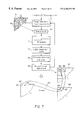
- FIG. 7 is a flowchart of the steps comprising the step of establishing a projector to camera mapping from FIG. 5 .
- FIG. 8 is a block diagram illustrating a resampling system.
- FIG. 9 is a block diagram illustrating one-dimensional forward mapping.
- FIG. 10 is a diagram illustrating forward mapping using a four-corner mapping paradigm.
- FIG. 11A is a block diagram illustrating one-dimensional inverse mapping.
- FIG. 11B is a diagram illustrating the nearest neighbor approach in forward mapping.
- FIG. 11C is a diagram illustrating of the nearest neighbor approach in reverse mapping.
- FIG. 12A is a block diagram illustrating a model of the effects of illumination.
- FIG. 12B is a block diagram of the model of FIG. 12A with a feedback mechanism.
- FIG. 12C is a diagram showing how different projectors contribute to a pixel in an overlapping region.
- FIG. 12D is a graph showing output (sensed) intensity versus input value.
- FIGS. 13A and 13B are schematic diagrams illustrating embodiments of the present invention in which the correction mapping occurs is applied to pixel data taken from the frame buffer.
- FIG. 13C is a schematic diagram illustrating an embodiment of the present invention in which the correction mapping is applied to pixel data before the pixel data is stored in the frame buffer.
- FIG. 13D is a schematic diagram illustrating an embodiment of the present invention having one frame buffer per projector.
- FIG. 13E is a schematic diagram illustrating an embodiment of the present invention having one frame buffer per color per projector.
- FIG. 14 is a schematic diagram illustrating an alternative embodiment of the present invention using a linear sensor.
- FIG. 15 is a diagram of a screen displayed from a fully overlapped small-fill-factor embodiment of the present invention.
- a preferred embodiment of the present invention employs multiple, overlapping projection displays. By tiling the screen with many such projection displays, each point on the entire screen surface is covered by one or more displays. No attempt is made to align the projectors, either mechanically or electrically, either in position, rotation, relative brightness, or relative hue. Instead, the present invention relies on the application of large amounts of computation to perform the perfect “alignment” of these display elements.
- FIG. 1 illustrates, for demonstration purposes, a 2 ⁇ 2 projector array embodiment 10 of the present invention.
- Four projectors P 1 -P 4 project their respective images I 1 -I 4 onto a screen 11 . Projections for two of the projectors, P 1 and P 4 , are indicated by lines 15 . No corrections have been made to the images I 1 -I 4 yet. Note that they are not aligned, and that they overlap, with some of the overlap regions identified by reference number 13 .
- the source of the images though not shown, may be any of the typical video or image sources, for example, a VCR, a laser disc player, or a computer.
- a camera 17 monitors the screen 11 during a calibration phase, or during frames stolen from a moving display.
- a picture of the screen 11 taken by the camera 17 is fed back to a computer 18 which also controls the projectors P 1 -P 4 .
- the computer 18 first calibrates the camera 17 with reference to the screen 11 , and then establishes a screen to projector mapping, which is used to distort images before they are sent to the projectors. These distortions compensate for the natural distortions of the system, resulting in a seamless, undistorted image composed from the four projectors.
- a euclidean, polar, spherical, or other coordinate system if appropriate for the screen, is erected in screen coordinate space S.
- Each projector has its own, local coordinate space P i .
- a map is established between the screen and each projector coordinate space via a measurement feedback system.
- this mapping is similar to the charts and atlases defined in differential geometry on manifolds.
- a single point in the screen coordinate system may be described by multiple charts, each corresponding to a different projector.
- a description may also contain color and intensity information.
- the active feedback system has the role of providing the invertible mapping between the screen coordinate system and each projector coordinate system.
- the practical techniques required for establishing this mapping are addressed below.
- the approach of computationally defining the mapping between screen and projection coordinate systems corrects a number of defects in existing approaches to tiling large arrays of projectors, in particular, relative displacement, relative rotation, scale factor differences, keystoning, and simple pincushion or barrel distortion. These geometric defects are corrected with a simple mapping of the desired screen coordinate to the point needed in one or more of the projector coordinate systems. Writing to the mapped projector pixel illuminates the desired screen point. These techniques may also be useful in improving the performance of single displays exhibiting difficult-to-correct distortions or intensity and color variations.
- each color may be written to the appropriate projector coordinate.
- FIG. 2A is a front view of the screen 11 of FIG. 1, showing the projected images I 1 -I 4 and all of the overlap regions 13 .
- “ABCD” is projected across the overlap.
- a first portion 12 of the text is projected in image I 2 .
- a second portion 14 is projected in image I 1 . Note that the two portions of text are not aligned.
- the text 14 of image I 1 is not oriented correctly with respect to the text of image I 2 .
- FIG. 2B is a view of the screen 11 after the methods of the present invention have been applied to the system.
- Images I 1 ′-I 4 ′ are the mapped images of I 1 -I 4 respectively.
- the regions included within dashed lines I 1 and I 4 correspond to the original projection areas of FIG. 2 A. They are still covered by the corresponding projectors but have been mapped out of the image. Overlap regions have been labeled O xyz where x, y and z refer to the images that overlap. Note that, without moving any of the projectors P 1 -P 4 or the screen 11 , and without making any adjustments to the projectors themselves, the text 16 is now projected seamlessly across the overlap area O 12 .
- the projector errors which are not easily correctable using these techniques are those which result in loss of resolution, i.e., defocusing, of the projected image. These include spherical aberration, field curvature, and longitudinal color aberration in the optical system.
- the pixel location calculation is performed at a resolution significantly higher than that of the screen, camera or projector coordinates, and the resulting sub-pixel location of the written point in projector space is used as the basis for an anti-aliased write operation, updating the intensities already present in the bitmap at that location.
- a preferred embodiment of the present invention writes the screen coordinate pixel into all of the overlapping projector bitmaps. A portion of the required intensity is allocated to each projector according to the relative distance of each written projector's pixels from that projector's boundary, resulting in a gradual transition from projector to projector as we scan across a region in the screen coordinate system.
- Projectors may have different relative intensities of the color components, either globally, or in a way which depends on the projector coordinate. These defects can be repaired by normalizing the written color intensity by a local, projector dependent, color mapping function. This technique, together with the gradual transitions between projectors described above, assures good color matching between displayed tiles on the screen.
- FIG. 3 shows for a single projector, formalized, the challenge is to display a bitmap image on a screen S.
- Each projector has its own bitmapped addressable space P i , which is projected onto S.
- FIG. 3 shows the functional relationship between the spaces and whether they are directly or indirectly measurable.
- the screen space S to camera space C relationship is directly measurable by placing a test chart over the screen 11 and taking a picture with the camera 17 .
- the projector P i to camera space C is directly measurable by projecting individual pixels in the projector and detecting where in camera space C they appear.
- the projector space P i to screen space S relationship SP i is not directly measurable, and is thus shown in dotted lines. It can, however, be composed from the two directly measurable relationships, or mappings.
- mappings between P i and S Once mappings are determined, it is possible to display a desired image anywhere on the screen 11 that a projector projects, correcting for all optical, overlap and intensity distortions using a process known as digital image warping. Approximations to these mappings are established using the camera 17 , along with photogrammetry and machine-vision techniques.
- the camera bitmap represents a snapshot of camera space C.
- mapping between C and S is established by taking a picture of a number of precise reference landmarks on S. Then, a number of pictures of P i projected onto S are taken. Both sets of mappings are composed to provide the mapping between P i and S. All of the mappings are bijective, i.e., they are one-to-one mappings, so they can be inverted as well. The present invention effectively establishes and uses these mappings.
- a preferred embodiment of the present invention comprises an M ⁇ N array of projectors, rear or front projecting onto a screen, as shown in FIG. 1 .
- the projectors are connected to a computer 18 which is in turn connected to a camera for feedback.
- the four projectors used are Epson Power-Lite 5000 liquid crystal display (LCD) projectors.
- Each projector is capable of displaying 800 by 600 pixels (SVGA resolution) at 450 lumens, making the system capable of a theoretical 1600 ⁇ 1200 pixel resolution.
- the computer is outfitted with Appian Graphic Jeronimo Video Cards and uses a Matrox Meteor Frame Grabber to digitize the NTSC input from the Pulnix TM540 CCD camera.
- the system of FIG. 1 is a basic building block which can be employed to build huge video walls composed of many more projectors and cameras.
- FIG. 4A is a block diagram illustrating the general scheme 300 of a preferred embodiment of the present invention.
- a calibration system 305 first calibrates the camera 309 .
- the calibrated camera 309 and the projection system 307 with all of the distortions it introduces, are then used to measure and compute a positional correction function or warp (box 311 ) and an intensity and color correction function of warp (box 313 ).
- the outcome of the calibration phase 301 is a two-dimensional lookup table 315 .
- the lookup table 315 is used by an image warper 317 to warp an image 319 to be displayed.
- an image warper 317 By applying the warping function of the lookup table 315 to the image 319 , a distorted or warped image is sent to the projectors.
- the warping compensates very closely for the distortions of the projection system 307 , so that the outcome is an undistorted picture 321 projected onto a projection surface such as a screen.
- FIG. 4B is a flowchart 20 of a preferred embodiment's method of producing mappings and corresponds to block 305 of FIG. 4 A.
- the camera is calibrated by producing a screen to camera mapping SC.
- positional mappings SP i are established for each projector P i (steps 21 , 23 , 27 ).
- color/intensity mappings are established for each projector P i (steps 24 , 25 , 26 ).
- step 27 except for calibrating the camera (step 31 ), this process is repeated for each projector.
- a preferred embodiment of the present invention achieves sub-pixel registration and positionally warps an image to create an imperceptibly positionally seamless image across a multiple channel projection system.
- a mapping between screen and projector space is established, and then is used to digitally warp the input image to account for geometrical and overlap distortions across the projection systems.
- FIG. 5 is a flowchart of the process of establishing the screen space to projector space mapping SP i , corresponding to step 23 of FIG. 4 B.
- the mapping is established using photogrammetry, machine vision and functional composition, in a four-step process.
- step 33 a projector to camera mapping P i C is established.
- step 35 noise introduced by various effects such as quantizing as well as optical effects, is filtered out of the mappings.
- step 37 the P i C mappings are composed with the screen to camera mapping SC derived in step 31 (FIG. 4 B), to produce a screen to projector mapping SP i . Note that in establishing the positional mappings, the pictures of the test charts taken by the camera may first have the background subtracted out.
- One embodiment takes a picture of a few landmark points and with these measurements, estimate parameters in a camera distortion model using non-linear optimization techniques.
- a model accounts for a cameras' position and angle relative to a screen, as well as lens parameters such as radial distortion, off-center distortion etc.
- the brute force approach trivially accounts for local distortions that are not accounted for in the analytical models of the first approach.
- An additional advantage of the brute force method is that it directly produces the two-dimensional lookup table mapping between screen space and camera space. This table is an input used by the present invention, so that even if the system were modeled in the traditional way, a similar table would have to be generated using the model parameters.
- FIG. 6 is a flowchart showing details of step 31 from FIG. 4B, establishing the screen to camera mapping SC.
- a test chart 43 is placed over the screen.
- the test chart comprises a grid of equally spaced squares or landmarks.
- a prototype chart has squares 10 mm wide, with 10 mm space between the squares.
- step 45 a picture of the test chart 43 is taken by the camera 17 (FIG. 1 ), providing a projection of an optically correct two-dimensional screen space onto camera space, represented by the two dimensional picture bitmap 47 .
- Each entry in the picture bitmap 47 represents an intensity value for the corresponding camera pixel.
- step 49 the picture 47 is thresholded.
- the process of thresholding creates a two dimensional array 51 with the same dimensions as the picture bitmap 47 , in which each entry is a one if the corresponding pixel value in the bitmap 47 is greater than or equal to a threshold value, or a zero if the corresponding pixel value in the bitmap 47 is less than the threshold value.
- a connected region array 55 is the same size as the threshold array 51 and is filled, in step 53 , with labels corresponding to the connected pixels in the array 51 . Pixels are connected if they neighbor each other on one of four sides, i.e., above, below, left, or right, and have a one in the corresponding threshold array 51 pixel. Each connected region is given a unique label which is placed into the corresponding element of each connected pixel. Here, four pixels make up one region and each has been assigned the label “5”.
- step 57 the bitmap 47 and connected region array 55 are used to create a list 59 of centroids.
- a centroid comprising an x-coordinate and a y-coordinate is computed for each connected region.
- the x-coordinate of centroid for a particular connected region is computed by averaging, for each pixel in a connected region, the contribution of each pixel value multiplied by its x-coordinate. For example, if two pixels having contributions of M 1 and M 2 , and x-coordinates X 1 and X 2 respectively, form a connected region, then the x-coordinate of their centroid is
- X centroid ( M 1 *X 1 +M 2 *X 2 )/( M 1 +M 2 )
- the y-coordinate is computed similarly.
- the camera has a resolution much finer than its pixel size. Because pixel values can range between 0 and 255 for high frequency objects such as squares, the dynamic range of the camera is extended well beyond the integer resolution of the camera.
- the result of applying this process to the picture of the test chart 43 comprising many squares is a list 59 of coordinate pairs which denote the positions in the picture of the centers of the squares, i.e,. centroids.
- the first entry in the list 59 is a coordinate pair 67 represented as (x 11 , y 11 ).
- This pair maps the center of square L 11 on the test chart 43 to location x 11 , y 11 in camera space 63 , as indicated by arrow 61 .
- this list 59 provides the screen to camera mapping SC.
- a simple heurisitic orders the centroids from the list 59 and places them into a two dimensional data structure 63 .
- the coordinate pair 67 from the list 59 is placed at location 65 in camera space.
- the resulting mapping 61 thus maps point 65 to the center C 11 of a test chart landmark. Those centroids not contained within the boundary of the largest rectangle within the projected area are eliminated.
- FIG. 7, corresponding to step 33 of FIG. 5, shows a similar procedure for establishing the projector space to camera space P i C mapping.
- a brute force approach is chosen over a more traditional parameter limiting approach.
- a test chart 71 is projected by the projectors.
- the landmarks 72 are preferably large enough to be visible to the camera 17 and to yield super resolution measurements, i.e., each landmark 72 must take up more than one camera pixel width, yet the landmarks 72 are also small enough so that as many landmarks can be displayed per picture as possible. In experiments, a 10 ⁇ 10 pixel block was chosen, resulting in approximately seven camera pixels being affected in each direction.
- the landmarks need not be projected in visible light.
- the landmarks may also be projected using non-visible light such as infrared or ultraviolet light. Of course, this requires an optical sensor which can sense non-visible light.
- the space 74 between landmarks presents an additional concern.
- a large space between landmarks tends to reduce the effect light from adjacent landmarks has on a particular landmarks' measurement.
- a small space between landmarks tends to reduce the number of required test chart pictures by having as many landmarks as possible on one screen.
- the landmarks are separated by 30 pixels, eliminating the measurable effect from adjacent landmarks, yet limiting the total number of required test screen pictures to sixteen per projector.
- step 73 the first of sixteen projector test charts 71 is projected onto the screen from the selected projector P i .
- a picture of the test chart 71 is taken by the camera 17 .
- the picture is thresholded in step 77 , preferably using the same threshold as in step 49 (FIG. 6 ).
- Connected pixels are commonly labeled in step 79 , and connected region centroids are calculated and ordered (step 81 ), resulting in a new two dimensional data structure 85 which represents the projector space to camera space mapping P i C.
- steps 73 - 81 are repeated for each of the sixteen projector test charts to produce a complete projector space to camera space mapping P i C.
- the result is an ordered list 85 of coordinate pairs corresponding to the positions of the centers of the landmark squares of the various test charts 71 .
- the first entry in the list 85 is a coordinate pair 86 represented as (p x11 , p y11 ).
- This pair maps the center of square 91 , generated by the first projected test chart 71 , from screen space 87 to location P x11 , P y11 in camera space 89 , as indicated by arrow 96 .
- the center of square 93 which was generated by the second projected test chart, is mapped to camera space location P x12 , P y12 , corresponding to entry 88 in the list 85 .
- list 85 provides the projector to camera mapping P i C.
- the next step is to compose both mappings and thereby achieve a mapping between projector and screen space.
- the screen space to camera space mapping SC and the projector space to camera space mapping P i C are both one-to-one mappings.
- a functional inversion may be approximated by using a bilinear approximation for points lying between known data points.
- Camera space C serves as an intermediary space and is composed out.
- the result is a screen space to projector space mapping SP i represented as a two-dimensional lookup table.
- the mapping can be inverted to a projector to screen mapping P i S by using a simple bilinear approximation with the inversion of neighboring points.
- the SP i mappings are stored as two-dimensional lookup tables. The spaces that they map from and to depend on the type of digital image warping performed. Since the function is invertible, it is trivial to invert the mapping to reverse the spaces being mapped from or to.
- FIG. 8 illustrates the process of warping used to display an input image 101 once the mappings have been established.
- Digital image warping is essentially an operation that redefines the spatial relationship between points in an image.
- the input image 101 to be displayed is a bitmap which is input to the resampling system 103 .
- the spatial transformation 105 and antialiasing filter 107 are essentially plug-ins, that is, various spatial transformations may be plugged into block 105 , and various filtering algorithms may be plugged into block 107 .
- the output 109 of the resampling system 103 is the pixel information which is sent to each projector.
- the mapping function may be represented by relating screen coordinates to projector coordinates
- [x,y] are the output image coordinates of pixels in a projector's space P i and [u,v] are the input image coordinates of a pixel in image, or screen, space S.
- the mapping function can be represented by relating projector coordinates to screen coordinates:
- Resampling must be performed because the input represents discrete samples of a continuous input image and the output represents discrete input that is made into a continuous signal by the projection system. The continuous input image is not available. Resampling is a means of interpolating the continuous input image from that discretized input image and then sampling at points in the input image space related to the output projector space by the spatial transformation.
- FIG. 9 illustrates one-dimensional forward mapping.
- a forward map 111 uses the transformation representation of Eq. (1) to map pixel coordinates 113 from the input image to output, or projector, coordinates 115 .
- Each input pixel A-G is mapped from integer coordinates to real number coordinates. This is illustrated in FIG. 9 by regularly spaced input and irregularly spaced output.
- the real-valued output presents complications such as leaving holes where discrete output values are unmapped. For example, no input pixel is mapped to output pixel D′.
- FIG. 10 shows that these complications may be avoided by using a four-comer mapping paradigm which maps square patches to output quadrilaterals in the projector space.
- the four corners 128 of a pixel 127 from a bit map 123 in image space are mapped to four points 130 in projector space 125 which form the corresponding square 129 .
- an additional concern is that a set of four corners might map either to a single output pixel, or, as shown in FIG. 10, across several output pixels.
- An embodiment of the present invention deals with the latter case by using an accumulator array at each output pixel and integrating the individual contributions to an output pixel based on the percentage of the output pixel covered by the output quadrilateral.
- the mapped square 129 contributes to each of the output pixels labeled 132 . Determining the percentage of the output pixel covered by an output quadrilateral requires clipping the output quadrilateral with the output pixel. Clipping requires intersection tests and thus, unfortunately, is very expensive.
- FIG. 11A illustrates one-dimensional inverse mapping.
- An inverse map 141 uses the mapping function of Eq. (2) to map projector coordinates 145 in projector space to input coordinates 143 .
- each projector pixel A′-G′ represented as an integer, is projected back into the image, as a real number in image coordinate space.
- the value of the projector pixel is determined by input pixels near the mapped input point. No accumulator array is required and all output pixels are colored. However, there is no guarantee that all input pixels are used, as indicated in FIG. 11A where input pixel D is unused. Thus, additional filtering must be applied to mitigate the introduction of unnecessary artifacts in the output.
- FIG. 11B illustrates use of the nearest neighbor approach in forward mapping.
- a pixel 205 from the input image 201 is mapped to real-number coordinates corresponding to some point 209 in projector space 203 .
- the mapping is represented by line 207 .
- the nearest integer pixel 211 to the point 209 is determined and the value of the input pixel 205 is written to the output pixel 211 .
- FIG. 11C illustrates use of the nearest neighbor approach with inverse mapping.
- a pixel 213 from projector space 203 is inverse mapped to real-number coordinates corresponding to some point 217 in image space 201 .
- the inverse mapping is represented by line 215 .
- the nearest input image integer pixel 219 to the point 217 is determined and the value of that input pixel 219 is written to the projector pixel 213 .
- bilinear interpolation In the case of forward mapping, one approach that is easily implemented is bilinear interpolation.
- a bilinear filter is implicit in the four-corner mapping with the accumulator discussed above with reference to forward mapping.
- the input image is mapped from screen space S to projector space P i and reconstructed using linear interpolation.
- the resulting continuous image is then integrated within each pixel boundary and the result placed into the corresponding pixel in the resulting bitmap. This is a very costly operation.
- Other reconstructions and subsequent integration are possible, however they are even more costly computationally and thus are rarely performed.
- Filtering can be employed in the resampling stage once it is determined where in the input to sample from. Because a determined point may not have integer coordinates, it is better to resample the image by first reconstructing a continuous representation around that point based on available samples, and resampling that representation at the desired point.
- a first order measure which serves as an upper bound for an M ⁇ N array of projectors, each with a resolution of Q ⁇ R pixels, is M*N*Q*R.
- the vertical and horizontal resolutions of the largest rectangle which can be inscribed within the bounds of the projected area i.e., the number of pixels which can be counted by tracing a line from left to right or top to bottom can vary quite extensively.
- lines drawn from top to bottom vary from 1230 pixels to 1300 pixels, and from left to right from 900 pixels to 1000 pixels. By no means does this represent a regular grid of pixels.
- color and intensity mappings are created for each output pixel that take into account the intensity and overlap distortions between and among the projectors. These mappings warp or pre-distort input images appropriately. The mapping are created by measuring distortions, using the positional relationships already established, along with the projectors and the calibration camera.
- the screen gain is not unity, “hot spots”, or localized bright spots, can appear, for example on an extremely reflective (high-gain) surface. It is difficult, if not impossible, to create a feedback system with such a screen using a single camera, because the hot spots may form blind spots for the feedback system.
- the single camera feedback embodiment of the present invention uses a near-unity gain screen because the diffusive screen eliminates the hot spot problem.
- Human perception aided by two eyes rather than one eye viewing the screen, is able to vastly reduce the blind spots in perceived vision of the screen.
- multiple cameras may be used to make a system that would not have blind spots in the aggregated image used for feedback. Since the multiple camera approach more accurately models human perception, the unity gain requirement from the use of single camera is lessened.
- CCDs are linear-intensity measurement devices.
- output devices are typically cathode ray tubes (CRTs).
- CRTs cathode ray tubes
- Gamma correction corrects for a functional relationship between the actual output intensity and the input which is approximately the ratio of the input and the maximum input taken to the gamma power.
- a gamma of one denotes a completely linear relationship.
- the gamma of the camera determines the fidelity with which the camera can distinguish output intensities, yielding higher fidelity for values of gamma near one.
- the camera's gamma if known apriori or measured, can have its effects compensated for in the camera output thus resulting in feedback input that is consistent with the real world.
- the exact relationship between input and output can be determined by simply measuring the relationship using the overlap region, and some cleverly selected test patterns on each projector whose measured intensities in the overlap regions are the same independently. When both are projected, the intensity in the overlap region is twice as large, but the measured value depends on the desired relationship. By scanning through intensities and noting the measured value in the overlap region one can derive the desired relationship.
- One of the main points of using a camera is to have feedback that lets one measure the brightness distortions across the output.
- Lenses typically have intensity distortion generally comprising vignetting, a high rolling off in sensitivity at the edges of a lens.
- One way to calibrate this effect out of the measured data sets would be to take a picture of a uniformly bright test screen and use that to determine the effect of the vignetting. This is a practice known as flat-fielding.
- An alternative is to physically model the distortions and estimate parameters in the model by measuring physically realizable test scenes.
- the area of the input picture used for feedback is limited to the portion corresponding to the inner part of the lens which tends to be much less distorted than the outer part. With this approach, intensity distortion can be ignored to some extent.
- color matching is performed either by using color filters with a monochromatic camera, or by using a color camera. The problem of creating a uniformly perceived red, green or blue screen is then accomplished by using feedback.
- color constancy is also determined by adjacent colors. Thus, if the positional color ratio distortion transition is smooth, the perceived change may be minimized and perceived color constancy maintained.
- a preferred embodiment of the present invention follows a strategy similar to that described previously for establishing a positional mapping, for creating a lookup table for each projector pixel that can be used to warp its intensity so that a uniformly bright intensity is displayed across the system. That is, taking one set of measurements and computing the desired mapping, taking into account all issues previously mentioned. This approach is complicated by the amount of modeling that must be done.
- ⁇ is some weight given to a projector's contribution to a pixel.
- FIG. 12A illustrates a model 151 of the measured output qi from the camera for each projector pixel i.
- the measured value q i is a function of the camera's position and orientation, the particular pixel's input value v i , and the values of the surrounding pixels.
- a transfer function g j that maps input values to output intensity contributions ⁇ j .
- a camera transfer function f for each screen position which maps brightness b(x,y) to camera measurement q j .
- the summing of light is accounted for by the adder 159 which adds up illumination contributions 153 from other pixels.
- the contribution 153 from pixel i is a product of a scalar ⁇ i (x,y), which represents geometric effects on the illuminations from pixel i, times the output intensity contribution ⁇ i of that pixel.
- This model 151 enables the computation of intensity measured at any one point, based on all input pixel values for all of the projectors. To display a uniform color across the system, the equations derived from the model must be solved, adding the constraints of the overlapping regions, etc. This requires that thousands of coupled equations be solved. Even in the linear case, iteration may be used to solve the problem.
- ⁇ is some weight given to a projector's contribution to a pixel.
- the actual implementation is complicated by the fact that in an overlap region 201 of two projections 209 , 211 , the contribution of each projector must be smoothly rolled off toward the projector's projection edge.
- a preferred embodiment accounts for this in the feedback loop with the reference. That is, the contributions to a point 203 within an overlap region 201 are determined by weighting the reference value based on the point's Manhattan pixel distance 205 from the closest edge 213 over the sum of all such distances 205 , 207 from each projection's edge 213 , 215 respectively.
- Manhattan distance is the smallest number of pixels encountered between a starting pixel to an ending pixel, where travel is only permitted in horizontal and vertical, i.e., not diagonal directions.
- a lookup table is preferably associated with each sample point in the map.
- the desired table for a particular color, i.e., red, green or blue, and position is created by varying the intensities of the landmarks of the projected test chart.
- FIG. 12D illustrates a sample input/output relationship 220 .
- the horizontal axis 221 represents input value, i.e., the value fed to a projector.
- the vertical axis represents output value, i.e., the intensity value registered by the camera.
- the relationship is defined by curve 225 .
- six sample points 227 are uniformly spaced across the full intensity range.
- Output values corresponding to input values between sampled points are linearly interpolated from the map 220 .
- six intensity mappings are stored in a table associated with each sample point. Note that because intensities are derived for a set of pixels, the map for a particular pixel must be bilinearly interpolated from the four regions surrounding that pixel or the output will not be smooth.
- this process can be repeated for each color. For example, in a system where a color wheel is employed one need only calibrate one color. In a system where three imaging units are used, sampling all three might be necessary.
- FIGS. 13A-13E illustrate several preferred configurations of the present invention with regard to the frame buffers, although the present invention is not limited to only these configurations.
- FIG. 13A illustrates a system in which pixel data from the input image 401 , which may be generated, for example, by a VCR, a laser disc player, a computer, or some other source, is stored in a frame buffer 405 which is typically within a computer 403 .
- the pixel correction function, or mapping 407 is applied to the pixel data between the frame buffer 405 and the display hardware 409 , which projects the corrected image onto a screen 411 .
- the pixel correction function 407 may comprise additional memory for storing corrected image pixel data.
- FIG. 13B illustrates a similar configuration in which the pixel correction function 407 A comprises a separate piece of hardware external to the computer 403 .
- FIG. 13C illustrates a system in which the correction function 413 is applied to the pixel data before being stored in the frame buffer 415 , so that the corrected pixel data is stored in the frame buffer, and the display hardware 409 is driven directly from the corrected pixel data.
- Different portions 415 A, 415 B of the frame buffer 415 are allocated to different projectors 409 . Because the projections from the various display hardware 409 , i.e., the projectors, overlap, the mapping function 413 may store pixel information associated with the overlap region redundantly in each frame buffer portion.
- FIG. 13D illustrates another system in which there is a separate frame buffer 419 for each projector 419 .
- the frame buffers may be fed from a common correction function 417 .
- a separate correction function would have to be applied to each frame buffer (not shown).
- FIG. 13E illustrates yet another system in which there is a separate frame buffer 423 for each of the colors, i.e., red (R), green (G) and blue (B) for each projector.
- the mapping 421 is virtually the same as the mapping 417 of FIG. 13D except for the multiple outputs per projector. Again, alternatively, the mappings may be applied after the frame buffers rather than before (not shown).
- one pixel at a time is illuminated. Because it is the only illuminated pixel, its position can be uniquely identified on a linear sensor. With a pair of such, preferably orthogonal, sensors, the screen coordinates of a projected single pixel can be uniquely determined. Such sensors are commercially available with resolutions up to 10,000 pixels for use in flat bed scanners.
- FIG. 14 illustrates one line sensor 106 .
- Each line sensor comprises a cylindrical lens 105 which focuses the light from a pixel 102 in one axis onto the linear sensor array 107 at a point 102 A. Light in the other axis falls on the sensor unfocused, from all directions.
- sensors cover only the overlap region between two or a small number of projectors. It should be possible to construct smooth high resolution atlases only from such local information. Such sensor splicing techniques may be used to fabricate very high resolution cameras, as well.
- Both rear and front projection techniques can be used, and the sensor can be located either on the same side of the screen as the projector, or on the opposite side.
- Rear projection and rear sensing if space is available, is perhaps superior, given the lack of interference from users blocking the light and sensing path.
- a spherical, hemispherical, or cylindrical screen may be employed, with users either inside or outside the screen, and with projection and sensing done from the opposite side of the screen.
- FIG. 15 illustrates a preferred embodiment for displaying high resolution screens with relatively low-resolution projectors uses small-fill factor projectors.
- Fill-factor is the portion of the pixel spacing which is illuminated.
- the magnified image appears as a set of small dots separated by black regions, where the dot spacing corresponds to the pixel spacing, while the size of the dots is substantially smaller.
- the expected usable pixel density rises as the square root of the number of projected images, due to statistical spread in the placement of the pixels.
- this embodiment is useful for perhaps doubling or tripling the effective linear pixel density, it may not be a cost effective technique to increase the density ten times, since this would require 100 low resolution projectors.
- a potential difficulty is the presence of moire patterns (aliasing) in the pixel pattern. This can be eliminated by predictable but random jitter introduced in the pixel placement.
- the display of static two dimensional images can be improved by the techniques described above, but we can apply these same techniques to the display of real time three dimensional images, as well.
- One approach is to measure the position of the viewer, and perform real time parallax correction on the displayed image.
- This technique could be used, for example, as a way of making a wall display appear as a window into an adjacent room or portion of a room.
- a full wall display could give the illusion of being part of a single, contiguous, larger space.
- a outside viewed hemispherical display could appear to be three dimensional physical object, viewable from any angle.
- Binocular cues could be provided by supplying each eye with a different image.
- Standard approaches to this problem include frame triggered shutters for each eye, projected polarization control, red/blue colored glasses.
- Another approach may be to project six colors, using distinct narrow band color filters for each eye.
- auxiliary ideas which complement the high resolution displays described here. Some examples include the incorporation of pen or finger locating techniques along with the display as a way of providing user input to a computer system using such displays.
- finger position may be sensed by using the change in the reflective characteristics of ground glass when a finger is placed over a portion of the glass.
- the presence of the finger dramatically changes the amount of light reflected from the surface of the glass, potentially allowing a sensor to detect the light change from the rear reflected image.
- calibration may be performed dynamically by stealing frames, i.e., taking an occasional frame or portion thereof and rather than displaying the usual picture, displaying a calibration pattern.
- a display output may be modified to account for some obstruction, possibly a moving obstruction, for a given viewpoint.
- Another embodiment employs the aforementioned techniques to correct for various types of distortion.
- the present invention may be used where the projected image changes from frame to frame, as, for example, in a movie or an animation.
Abstract
Description
Claims (91)
Priority Applications (2)
| Application Number | Priority Date | Filing Date | Title |
|---|---|---|---|
| US09/181,320 US6456339B1 (en) | 1998-07-31 | 1998-10-28 | Super-resolution display |
| PCT/US1999/015026 WO2000007376A1 (en) | 1998-07-31 | 1999-07-01 | Super-resolution display |
Applications Claiming Priority (2)
| Application Number | Priority Date | Filing Date | Title |
|---|---|---|---|
| US9496298P | 1998-07-31 | 1998-07-31 | |
| US09/181,320 US6456339B1 (en) | 1998-07-31 | 1998-10-28 | Super-resolution display |
Publications (1)
| Publication Number | Publication Date |
|---|---|
| US6456339B1 true US6456339B1 (en) | 2002-09-24 |
Family
ID=26789394
Family Applications (1)
| Application Number | Title | Priority Date | Filing Date |
|---|---|---|---|
| US09/181,320 Expired - Lifetime US6456339B1 (en) | 1998-07-31 | 1998-10-28 | Super-resolution display |
Country Status (2)
| Country | Link |
|---|---|
| US (1) | US6456339B1 (en) |
| WO (1) | WO2000007376A1 (en) |
Cited By (259)
| Publication number | Priority date | Publication date | Assignee | Title |
|---|---|---|---|---|
| US20010024231A1 (en) * | 2000-03-21 | 2001-09-27 | Olympus Optical Co., Ltd. | Stereoscopic image projection device, and correction amount computing device thereof |
| US20020008697A1 (en) * | 2000-03-17 | 2002-01-24 | Deering Michael F. | Matching the edges of multiple overlapping screen images |
| US20020012004A1 (en) * | 2000-03-17 | 2002-01-31 | Deering Michael F. | Blending the edges of multiple overlapping screen images |
| US20020015052A1 (en) * | 2000-03-17 | 2002-02-07 | Deering Michael F. | Graphics system configured to perform distortion correction |
| US20020024612A1 (en) * | 2000-08-30 | 2002-02-28 | Takaaki Gyoten | Video projecting system |
| US20020041364A1 (en) * | 2000-10-05 | 2002-04-11 | Ken Ioka | Image projection and display device |
| US20020093631A1 (en) * | 2000-11-30 | 2002-07-18 | Randall Melton | Method and system for automated convergence and focus verification of projected images |
| US20020109792A1 (en) * | 2001-02-15 | 2002-08-15 | Mark Champion | Two-dimensional buffer pages using memory bank alternation |
| US20020109693A1 (en) * | 2001-02-15 | 2002-08-15 | Mark Champion | Checkerboard buffer using two-dimensional buffer pages |
| US20020158877A1 (en) * | 2000-11-22 | 2002-10-31 | Guckenberger Ronald James | Shadow buffer control module method and software construct for adjusting per pixel raster images attributes to screen space and projector features for digital wrap, intensity transforms, color matching, soft-edge blending and filtering for multiple projectors and laser projectors |
| US20020180727A1 (en) * | 2000-11-22 | 2002-12-05 | Guckenberger Ronald James | Shadow buffer control module method and software construct for adjusting per pixel raster images attributes to screen space and projector features for digital warp, intensity transforms, color matching, soft-edge blending, and filtering for multiple projectors and laser projectors |
| US20020180766A1 (en) * | 2000-08-28 | 2002-12-05 | Osamu Wada | Environment-adapted image display system, image processing method, and information storage medium |
| US20030044082A1 (en) * | 2001-08-30 | 2003-03-06 | Osamu Katayama | Image processing apparatus having processing operation by coordinate calculation |
| US20030043303A1 (en) * | 2001-06-12 | 2003-03-06 | Bonaventure Karuta | System and method for correcting multiple axis displacement distortion |
| US20030058368A1 (en) * | 2001-09-24 | 2003-03-27 | Mark Champion | Image warping using pixel pages |
| US20030063226A1 (en) * | 2000-03-31 | 2003-04-03 | Gibbon Michael A. | Digital projection equipment and techniques |
| US6545718B1 (en) * | 1999-06-07 | 2003-04-08 | Sony Corporation | Cathode ray tube and apparatus and method of controlling brightness |
| US20030067587A1 (en) * | 2000-06-09 | 2003-04-10 | Masami Yamasaki | Multi-projection image display device |
| US20030076419A1 (en) * | 2001-10-22 | 2003-04-24 | Eastman Kodak Company | Method and apparatus for determining and correcting for illumination variations in a digital projector |
| US20030128337A1 (en) * | 2001-12-07 | 2003-07-10 | Jaynes Christopher O. | Dynamic shadow removal from front projection displays |
| US6592225B2 (en) * | 2001-07-02 | 2003-07-15 | Virtual Environment Technologies, Llc | Multiple projected image edge blender apparatus and method |
| US20030156262A1 (en) * | 2000-07-03 | 2003-08-21 | Baker Kenneth T | Equipment and techniques for invisible seaming of multiple projection displays |
| US20030184665A1 (en) * | 2002-03-21 | 2003-10-02 | International Business Machines Corporation | Anti-moire pixel array having multiple pixel types |
| US20030189578A1 (en) * | 2000-11-17 | 2003-10-09 | Alcorn Byron A. | Systems and methods for rendering graphical data |
| US20030206179A1 (en) * | 2000-03-17 | 2003-11-06 | Deering Michael F. | Compensating for the chromatic distortion of displayed images |
| US20040004692A1 (en) * | 1999-11-19 | 2004-01-08 | Semiconductor Energy Laboratory Co., Ltd. | Defective pixel compensation system and display device using the system |
| WO2004010211A1 (en) * | 2002-07-24 | 2004-01-29 | Unisys Corporation | Improvements relating to pixellated display and imaging devices |
| US6695451B1 (en) * | 1997-12-12 | 2004-02-24 | Hitachi, Ltd. | Multi-projection image display device |
| US6715888B1 (en) * | 2003-03-21 | 2004-04-06 | Mitsubishi Electric Research Labs, Inc | Method and system for displaying images on curved surfaces |
| US20040066454A1 (en) * | 2002-07-03 | 2004-04-08 | Topcon Corporation | Device and method of measuring data for calibration, program for measuring data for calibration, program recording medium readable with computer, and image data processing device |
| US6721694B1 (en) * | 1998-10-13 | 2004-04-13 | Raytheon Company | Method and system for representing the depths of the floors of the oceans |
| US20040085477A1 (en) * | 2002-10-30 | 2004-05-06 | The University Of Chicago | Method to smooth photometric variations across multi-projector displays |
| US6733138B2 (en) * | 2001-08-15 | 2004-05-11 | Mitsubishi Electric Research Laboratories, Inc. | Multi-projector mosaic with automatic registration |
| US6755537B1 (en) * | 2003-03-21 | 2004-06-29 | Mitsubishi Electric Research Laboratories, Inc. | Method for globally aligning multiple projected images |
| US20040138561A1 (en) * | 2002-12-06 | 2004-07-15 | Jan Lewandowski | Ultrasonic detection of ear disorders |
| US6764185B1 (en) * | 2003-08-07 | 2004-07-20 | Mitsubishi Electric Research Laboratories, Inc. | Projector as an input and output device |
| US6771272B2 (en) * | 2000-03-17 | 2004-08-03 | Sun Microsystems, Inc. | Graphics system having a super-sampled sample buffer with hot spot correction |
| US20040150795A1 (en) * | 2002-05-31 | 2004-08-05 | Olympus Corporation | Multiprojection system and method of acquiring correction data in multiprojection system |
| US20040165068A1 (en) * | 2003-02-25 | 2004-08-26 | Jane Rone Fue | Projector color calibration device and method |
| US20040184011A1 (en) * | 2003-03-21 | 2004-09-23 | Ramesh Raskar | Self-configurable ad-hoc projector cluster |
| US6804406B1 (en) * | 2000-08-30 | 2004-10-12 | Honeywell International Inc. | Electronic calibration for seamless tiled display using optical function generator |
| EP1473933A2 (en) * | 2003-05-02 | 2004-11-03 | Seiko Epson Corporation | Image processing system, projector, information storage medium and image processing method |
| WO2004112402A1 (en) * | 2003-06-13 | 2004-12-23 | Cyviz As | Method and device for combining images from at least two light projectors |
| US20050024368A1 (en) * | 2001-02-15 | 2005-02-03 | Xiping Liu | Two dimensional buffer pages |
| US20050030486A1 (en) * | 2003-08-06 | 2005-02-10 | Lee Johnny Chung | Method and system for calibrating projectors to arbitrarily shaped surfaces with discrete optical sensors mounted at the surfaces |
| US6864888B1 (en) * | 1999-02-25 | 2005-03-08 | Lockheed Martin Corporation | Variable acuity rendering for a graphic image processing system |
| US20050057572A1 (en) * | 2001-02-15 | 2005-03-17 | Sony Corporation | Checkerboard buffer |
| US20050083402A1 (en) * | 2002-10-31 | 2005-04-21 | Stefan Klose | Auto-calibration of multi-projector systems |
| US20050099608A1 (en) * | 2002-10-24 | 2005-05-12 | Geert Matthys | Bundled light based alignment and maintenance tool for projection systems |
| US20050104890A1 (en) * | 2001-02-15 | 2005-05-19 | Sony Corporation | Dynamic buffer pages |
| US20050110959A1 (en) * | 2003-10-15 | 2005-05-26 | Seiko Epson Corporation | Multi-projection display |
| US20050116968A1 (en) * | 2003-12-02 | 2005-06-02 | John Barrus | Multi-capability display |
| US20050140568A1 (en) * | 2003-12-10 | 2005-06-30 | Seiko Epson Corporation | Image display control method, apparatus for controlling image display, and program for controlling image display |
| EP1554889A1 (en) * | 2002-10-21 | 2005-07-20 | Imax Corporation | Equipment, systems and methods for control of color in projection displays |
| US20050206857A1 (en) * | 2004-03-22 | 2005-09-22 | Seiko Epson Corporation | Image correction method for multi-projection system |
| US20050228634A1 (en) * | 1999-12-10 | 2005-10-13 | Microsoft Corporation | Geometric model database for use in ubiquitous computing |
| US20050225640A1 (en) * | 2004-04-08 | 2005-10-13 | Olympus Corporation | Calibration camera device and calibration system |
| US20050230641A1 (en) * | 2004-04-05 | 2005-10-20 | Won Chun | Data processing for three-dimensional displays |
| US20050253974A1 (en) * | 2005-01-20 | 2005-11-17 | Joshua Elliott | Pixellated display and imaging devices |
| US20050278582A1 (en) * | 2004-06-15 | 2005-12-15 | Willis Thomas E | Repairing microdisplay frame buffers |
| US20060007406A1 (en) * | 2002-10-21 | 2006-01-12 | Sean Adkins | Equipment, systems and methods for control of color in projection displays |
| US20060012759A1 (en) * | 2004-07-16 | 2006-01-19 | Nec Viewtechnology, Ltd. | Multiscreen display system, multiscreen display method, luminance correction method, and programs |
| US7006669B1 (en) * | 2000-12-31 | 2006-02-28 | Cognex Corporation | Machine vision method and apparatus for thresholding images of non-uniform materials |
| US20060098894A1 (en) * | 2004-11-05 | 2006-05-11 | Dicarlo Jeffrey M | Method and system for correcting the effect of non-uniform illumination |
| WO2006014598A3 (en) * | 2004-07-08 | 2006-06-15 | Imax Corp | Equipment and methods for the display of high resolution images using multiple projection displays |
| US20060152680A1 (en) * | 2003-03-26 | 2006-07-13 | Nobuyuki Shibano | Method for creating brightness filter and virtual space creation system |
| US20060170956A1 (en) * | 2005-01-31 | 2006-08-03 | Jung Edward K | Shared image devices |
| US20060181687A1 (en) * | 2005-02-14 | 2006-08-17 | Seiko Epson Corporation | Image processing system, projector, and image processing method |
| US20060187476A1 (en) * | 2005-02-23 | 2006-08-24 | Seiko Epson Corporation | Image display device, method of generating correction value of image display device, program for generating correction value of image display device, and recording medium recording program thereon |
| EP1699035A1 (en) * | 2003-12-25 | 2006-09-06 | National Institute of Information and Communications Technology Incorporated Administrative Agency | Display system |
| US20060228018A1 (en) * | 2005-04-12 | 2006-10-12 | Gil Abramovich | Reconfigurable machine vision system |
| US20060238723A1 (en) * | 2005-04-22 | 2006-10-26 | El-Ghoroury Hussein S | Low profile, large screen display using a rear projection array system |
| US20070008251A1 (en) * | 2005-07-07 | 2007-01-11 | Makoto Kohno | Method of correcting nonuniformity of pixels in an oled |
| US20070030452A1 (en) * | 2005-08-08 | 2007-02-08 | N-Lighten Technologies | Image adaptation system and method |
| US20070035707A1 (en) * | 2005-06-20 | 2007-02-15 | Digital Display Innovations, Llc | Field sequential light source modulation for a digital display system |
| US20070035706A1 (en) * | 2005-06-20 | 2007-02-15 | Digital Display Innovations, Llc | Image and light source modulation for a digital display system |
| US20070047838A1 (en) * | 2005-08-30 | 2007-03-01 | Peyman Milanfar | Kernel regression for image processing and reconstruction |
| US20070052695A1 (en) * | 2005-09-07 | 2007-03-08 | Barnes Ted W | Generating and displaying spatially offset sub-frames |
| US20070058861A1 (en) * | 2005-09-09 | 2007-03-15 | Seiko Epson Corporation | Projection system, information processing apparatus and method of generating modified-image data |
| US20070091434A1 (en) * | 2005-10-21 | 2007-04-26 | Hewlett-Packard Development Company, L.P. | Luminance adjustment |
| US20070103583A1 (en) * | 2005-10-21 | 2007-05-10 | Burnett William R | Display wall comprising multiple displays and method of operation thereof |
| US20070171380A1 (en) * | 2006-01-26 | 2007-07-26 | Christie Digital Systems Inc. | Calibration of a super-resolution display |
| US20070188493A1 (en) * | 2002-10-04 | 2007-08-16 | Sony Corporation | Display apparatus, image processing apparatus and image processing method, imaging apparatus, and program |
| US20070188719A1 (en) * | 2006-02-15 | 2007-08-16 | Mersive Technologies, Llc | Multi-projector intensity blending system |
| US20070195285A1 (en) * | 2006-02-15 | 2007-08-23 | Mersive Technologies, Llc | Hybrid system for multi-projector geometry calibration |
| US20070217005A1 (en) * | 2006-03-20 | 2007-09-20 | Novet Thomas E | Ambient light absorbing screen |
| US20070222860A1 (en) * | 2006-03-27 | 2007-09-27 | Funai Electric Co., Ltd. | Display apparatus, burn-in correction system and burn-in correction method |
| WO2007111589A1 (en) | 2006-03-28 | 2007-10-04 | Thomson Licensing | Method and apparatus for performing edge blending using production switchers |
| US20070242280A1 (en) * | 2006-04-12 | 2007-10-18 | Dickinson Brian R | Digitizer adapter |
| US20070242240A1 (en) * | 2006-04-13 | 2007-10-18 | Mersive Technologies, Inc. | System and method for multi-projector rendering of decoded video data |
| US20070268306A1 (en) * | 2006-04-21 | 2007-11-22 | Mersive Technologies, Inc. | Image-based parametric projector calibration |
| US20070273795A1 (en) * | 2006-04-21 | 2007-11-29 | Mersive Technologies, Inc. | Alignment optimization in image display systems employing multi-camera image acquisition |
| US20070291047A1 (en) * | 2006-06-16 | 2007-12-20 | Michael Harville | System and method for generating scale maps |
| US20070291233A1 (en) * | 2006-06-16 | 2007-12-20 | Culbertson W Bruce | Mesh for rendering an image frame |
| US20070291185A1 (en) * | 2006-06-16 | 2007-12-20 | Gelb Daniel G | System and method for projecting multiple image streams |
| US20070291184A1 (en) * | 2006-06-16 | 2007-12-20 | Michael Harville | System and method for displaying images |
| US20070291189A1 (en) * | 2006-06-16 | 2007-12-20 | Michael Harville | Blend maps for rendering an image frame |
| US20080001977A1 (en) * | 2006-06-30 | 2008-01-03 | Aufranc Richard E | Generating and displaying spatially offset sub-frames |
| US20080002160A1 (en) * | 2006-06-30 | 2008-01-03 | Nelson Liang An Chang | System and method for generating and displaying sub-frames with a multi-projector system |
| EP1876814A1 (en) * | 2006-07-07 | 2008-01-09 | Barco NV | Non-linear image mapping using a plurality of non-coplanar clipping planes |
| US20080024469A1 (en) * | 2006-07-31 | 2008-01-31 | Niranjan Damera-Venkata | Generating sub-frames for projection based on map values generated from at least one training image |
| US20080024862A1 (en) * | 2006-07-26 | 2008-01-31 | Compal Communications, Inc. | Rear projection display system |
| US20080024683A1 (en) * | 2006-07-31 | 2008-01-31 | Niranjan Damera-Venkata | Overlapped multi-projector system with dithering |
| US20080036971A1 (en) * | 2006-08-08 | 2008-02-14 | Seiko Epson Corporation | Display device, multi-display system, and image information generation method |
| US20080111763A1 (en) * | 2006-10-04 | 2008-05-15 | Rochester Institute Of Technology | Aspect-ratio independent, multimedia capture, editing, and presentation systems and methods thereof |
| US20080111926A1 (en) * | 2006-11-10 | 2008-05-15 | Coretronic Corporation | Projection system and adjusting method thereof |
| US20080118178A1 (en) * | 2006-11-20 | 2008-05-22 | Way Olan C | Display systems and methods for eliminating mullions |
| US20080129967A1 (en) * | 2006-04-21 | 2008-06-05 | Mersive Technologies, Inc. | Projector operation through surface fitting of 3d measurements |
| US20080143969A1 (en) * | 2006-12-15 | 2008-06-19 | Richard Aufranc | Dynamic superposition system and method for multi-projection display |
| US20080143978A1 (en) * | 2006-10-31 | 2008-06-19 | Niranjan Damera-Venkata | Image display system |
| US20080174516A1 (en) * | 2007-01-24 | 2008-07-24 | Jing Xiao | Mosaicing of View Projections |
| US20080180467A1 (en) * | 2006-04-13 | 2008-07-31 | Mersive Technologies, Inc. | Ultra-resolution display technology |
| US20080218853A1 (en) * | 2007-03-06 | 2008-09-11 | Ostendo Technologies, Inc. | Micro-structure based screen system for use in rear projection array display systems |
| US20080246781A1 (en) * | 2007-03-15 | 2008-10-09 | Scalable Display Technologies, Inc. | System and method for providing improved display quality by display adjustment and image processing using optical feedback |
| US20080260279A1 (en) * | 2004-02-01 | 2008-10-23 | Rafael - Armament Development Authority Ltd. | Super-resolution image processing |
| US20080266321A1 (en) * | 2007-04-30 | 2008-10-30 | Richard Aufranc | System and method for masking and overlaying images in multiple projector system |
| US20080285627A1 (en) * | 2005-04-22 | 2008-11-20 | Thales | Method for Synchronisation and Control in Wireless Communication Systems |
| US20090009723A1 (en) * | 2004-07-16 | 2009-01-08 | Keller Kurtis P | Methods, Systems, and Computer Program Products for Full Spectrum Projection |
| US20090033874A1 (en) * | 2007-07-31 | 2009-02-05 | Richard Aufranc | System and method of projecting an image using a plurality of projectors |
| US20090040133A1 (en) * | 2007-08-09 | 2009-02-12 | Robert Mark Clodfelter | Multiple display channel system with high dynamic range |
| US20090051790A1 (en) * | 2007-08-21 | 2009-02-26 | Micron Technology, Inc. | De-parallax methods and apparatuses for lateral sensor arrays |
| US20090115915A1 (en) * | 2006-08-09 | 2009-05-07 | Fotonation Vision Limited | Camera Based Feedback Loop Calibration of a Projection Device |
| US20090135200A1 (en) * | 2005-06-28 | 2009-05-28 | Mark Alan Schultz | Selective Edge Blending Based on Displayed Content |
| US20090141255A1 (en) * | 2007-11-30 | 2009-06-04 | Seiko Epson Corporation | Projection image display position control device, projection image display position control method, and projection system |
| US20090207383A1 (en) * | 2005-06-30 | 2009-08-20 | Keiichiroh Hirahara | Projected image display unit |
| US20090262260A1 (en) * | 2008-04-17 | 2009-10-22 | Mersive Technologies, Inc. | Multiple-display systems and methods of generating multiple-display images |
| US20090284604A1 (en) * | 2008-05-13 | 2009-11-19 | Wistron Corporation | Method and a device for adjusting a color temperature coordinate value measured by a display color analyzer |
| US20100060803A1 (en) * | 2008-09-08 | 2010-03-11 | Apple Inc. | Projection systems and methods |
| US20100079653A1 (en) * | 2008-09-26 | 2010-04-01 | Apple Inc. | Portable computing system with a secondary image output |
| US20100079468A1 (en) * | 2008-09-26 | 2010-04-01 | Apple Inc. | Computer systems and methods with projected display |
| US20100101308A1 (en) * | 2007-02-22 | 2010-04-29 | The University Of North Carolina At Chapel Hill | Methods and systems for multiforce high throughput screening |
| US20100103379A1 (en) * | 2008-10-24 | 2010-04-29 | Reinhold Fiess | Method for generating an image and a projector and a cell phone having a projector |
| US20100118050A1 (en) * | 2008-11-07 | 2010-05-13 | Clodfelter Robert M | Non-linear image mapping using a plurality of non-linear image mappers of lesser resolution |
| US7717574B1 (en) | 2005-09-30 | 2010-05-18 | Obscura Digital, Inc. | Method for simplifying the imaging of objects with non-Lambertian surfaces |
| US20100128228A1 (en) * | 2008-11-26 | 2010-05-27 | Seiko Epson Corporation | Projector and projector system |
| US20100171765A1 (en) * | 2008-12-29 | 2010-07-08 | Lg Electronics Inc. | Digital television and method of displaying contents using the same |
| US7782365B2 (en) | 2005-06-02 | 2010-08-24 | Searete Llc | Enhanced video/still image correlation |
| US20100231811A1 (en) * | 2009-03-12 | 2010-09-16 | Canon Kabushiki Kaisha | Image projection system with keystone correction |
| US20100238188A1 (en) * | 2009-03-20 | 2010-09-23 | Sean Miceli | Efficient Display of Virtual Desktops on Multiple Independent Display Devices |
| US20100245684A1 (en) * | 2009-03-27 | 2010-09-30 | Jing Xiao | Resolution Scalable View Projection |
| US20100253861A1 (en) * | 2008-01-15 | 2010-10-07 | Yoshihiro Tomaru | Display |
| WO2010148303A2 (en) | 2009-06-18 | 2010-12-23 | Scalable Display Technologies, Inc. | System and method for injection of mapping functions |
| US20110007326A1 (en) * | 2009-07-08 | 2011-01-13 | Steinbichler Optotechnik Gmbh | Method for the determination of the 3d coordinates of an object |
| US7876357B2 (en) | 2005-01-31 | 2011-01-25 | The Invention Science Fund I, Llc | Estimating shared image device operational capabilities or resources |
| US20110057943A1 (en) * | 2009-09-10 | 2011-03-10 | Victor Ivashin | Balancing Luminance Disparity in a Display by Multiple Projectors |
| US7920169B2 (en) | 2005-01-31 | 2011-04-05 | Invention Science Fund I, Llc | Proximity of shared image devices |
| US7962629B2 (en) | 2005-06-17 | 2011-06-14 | Tessera Technologies Ireland Limited | Method for establishing a paired connection between media devices |
| US20110216985A1 (en) * | 2010-03-05 | 2011-09-08 | Ya-Ti Peng | System, method, and computer program product for picture resizing |
| US20110228175A1 (en) * | 2010-03-22 | 2011-09-22 | Microvision, Inc. | Projection System and Corresponding Method |
| US20110234922A1 (en) * | 2010-03-26 | 2011-09-29 | Steve Nelson | Correcting Row and Column Shifts in a Calibration Matrix for a Projection System |
| US20110234896A1 (en) * | 2010-03-26 | 2011-09-29 | Victor Ivashin | System and Method for Displaying Remote Content Through Multiple Projectors |
| US20110234920A1 (en) * | 2010-03-24 | 2011-09-29 | Steve Nelson | Method for Creating Blending Ramps for Complex Projector Image Overlaps |
| CN101208738B (en) * | 2005-04-11 | 2011-11-09 | 波利维森有限公司 | Automatic projection calibration |
| US20110321111A1 (en) * | 2010-06-29 | 2011-12-29 | Canon Kabushiki Kaisha | Dynamic layout of content for multiple projectors |
| US20120050689A1 (en) * | 2010-09-01 | 2012-03-01 | International Business Machines Corporation | Modifying application windows based on projection surface characteristics |
| US20120098937A1 (en) * | 2009-04-28 | 2012-04-26 | Behzad Sajadi | Markerless Geometric Registration Of Multiple Projectors On Extruded Surfaces Using An Uncalibrated Camera |
| US20120120372A1 (en) * | 2010-11-15 | 2012-05-17 | Scalable Display Technologies, Inc. | System and method for calibrating a display system using manual and semi-manual techniques |
| US8262236B2 (en) | 2008-06-17 | 2012-09-11 | The Invention Science Fund I, Llc | Systems and methods for transmitting information associated with change of a projection surface |
| US8267526B2 (en) | 2008-06-17 | 2012-09-18 | The Invention Science Fund I, Llc | Methods associated with receiving and transmitting information related to projection |
| US20120236116A1 (en) * | 2011-03-18 | 2012-09-20 | Optoma Corporation | Decoder, projection device, and image processing method |
| US20120274732A1 (en) * | 2011-04-29 | 2012-11-01 | Kar-Han Tan | Systems and methods for reducing video crosstalk |
| US8308304B2 (en) | 2008-06-17 | 2012-11-13 | The Invention Science Fund I, Llc | Systems associated with receiving and transmitting information related to projection |
| US20120300044A1 (en) * | 2011-05-25 | 2012-11-29 | Thomas Clarence E | Systems and Methods for Alignment, Calibration and Rendering for an Angular Slice True-3D Display |
| US8328365B2 (en) | 2009-04-30 | 2012-12-11 | Hewlett-Packard Development Company, L.P. | Mesh for mapping domains based on regularized fiducial marks |
| US20120320342A1 (en) * | 2005-12-06 | 2012-12-20 | Dolby Laboratories Licensing Corporation | Multi-Segment Imager |
| US8350946B2 (en) | 2005-01-31 | 2013-01-08 | The Invention Science Fund I, Llc | Viewfinder for shared image device |
| US8363067B1 (en) | 2009-02-05 | 2013-01-29 | Matrox Graphics, Inc. | Processing multiple regions of an image in a graphics display system |
| US8376558B2 (en) | 2008-06-17 | 2013-02-19 | The Invention Science Fund I, Llc | Systems and methods for projecting in response to position change of a projection surface |
| US8384005B2 (en) | 2008-06-17 | 2013-02-26 | The Invention Science Fund I, Llc | Systems and methods for selectively projecting information in response to at least one specified motion associated with pressure applied to at least one projection surface |
| US20130063408A1 (en) * | 2010-05-21 | 2013-03-14 | Isiqiri Interface Technologies Gmbh | Projection device, which comprises a projector, a projection surface, and a data processing system, and method for operating said projection device |
| US20130114892A1 (en) * | 2011-11-09 | 2013-05-09 | Canon Kabushiki Kaisha | Method and device for generating a super-resolution image portion |
| US8449121B2 (en) * | 2007-08-07 | 2013-05-28 | Seiko Epson Corporation | Image processing system, projector, method and computer program product |
| US20130176400A1 (en) * | 2012-01-05 | 2013-07-11 | Electronics And Telecommunications Research Institute | Apparatus and method of automatically correcting brightness of images captured by multiple cameras |
| US20130222386A1 (en) * | 2012-02-23 | 2013-08-29 | Canon Kabushiki Kaisha | Image processing for projection on a projection screen |
| US20130229629A1 (en) * | 2012-03-02 | 2013-09-05 | Mitsubishi Electric Corporation | Multi-screen display device |
| US8538132B2 (en) | 2010-09-24 | 2013-09-17 | Apple Inc. | Component concentricity |
| US8567953B2 (en) | 2005-04-26 | 2013-10-29 | Imax Corporation | Systems and methods for projecting composite images |
| US8586368B2 (en) | 2009-06-25 | 2013-11-19 | The University Of North Carolina At Chapel Hill | Methods and systems for using actuated surface-attached posts for assessing biofluid rheology |
| WO2013179294A1 (en) * | 2012-06-02 | 2013-12-05 | Maradin Technologies Ltd. | System and method for correcting optical distortions when projecting 2d images onto 2d surfaces |
| US8602564B2 (en) | 2008-06-17 | 2013-12-10 | The Invention Science Fund I, Llc | Methods and systems for projecting in response to position |
| US8606383B2 (en) | 2005-01-31 | 2013-12-10 | The Invention Science Fund I, Llc | Audio sharing |
| US8608321B2 (en) | 2008-06-17 | 2013-12-17 | The Invention Science Fund I, Llc | Systems and methods for projecting in response to conformation |
| US20140031665A1 (en) * | 2012-07-25 | 2014-01-30 | Covidien Lp | Telecentric Scale Projection System for Real-Time In-Situ Surgical Metrology |
| US8641203B2 (en) | 2008-06-17 | 2014-02-04 | The Invention Science Fund I, Llc | Methods and systems for receiving and transmitting signals between server and projector apparatuses |
| US8681225B2 (en) | 2005-06-02 | 2014-03-25 | Royce A. Levien | Storage access technique for captured data |
| US20140125957A1 (en) * | 2012-11-05 | 2014-05-08 | Samsung Electronics Co., Ltd. | Light field display apparatus and method |
| US8723787B2 (en) | 2008-06-17 | 2014-05-13 | The Invention Science Fund I, Llc | Methods and systems related to an image capture projection surface |
| US8733952B2 (en) | 2008-06-17 | 2014-05-27 | The Invention Science Fund I, Llc | Methods and systems for coordinated use of two or more user responsive projectors |
| US8761596B2 (en) | 2008-09-26 | 2014-06-24 | Apple Inc. | Dichroic aperture for electronic imaging device |
| US8817111B2 (en) | 2012-04-19 | 2014-08-26 | Scalable Display Technologies, Inc. | System and method of calibrating a display system free of variation in system input resolution |
| US8820939B2 (en) | 2008-06-17 | 2014-09-02 | The Invention Science Fund I, Llc | Projection associated methods and systems |
| US20140293294A1 (en) * | 2011-11-28 | 2014-10-02 | Brainlab Ag | Method and device for calibrating a projection device |
| US8857999B2 (en) | 2008-06-17 | 2014-10-14 | The Invention Science Fund I, Llc | Projection in response to conformation |
| US8902320B2 (en) | 2005-01-31 | 2014-12-02 | The Invention Science Fund I, Llc | Shared image device synchronization or designation |
| US20150015785A1 (en) * | 2006-01-31 | 2015-01-15 | Andrew Flessas | Robotically controlled entertainment elements |
| US8936367B2 (en) | 2008-06-17 | 2015-01-20 | The Invention Science Fund I, Llc | Systems and methods associated with projecting in response to conformation |
| US20150029077A1 (en) * | 2013-07-24 | 2015-01-29 | International Business Machines Corporation | Sharing an overlapping region in a display |
| US20150029465A1 (en) * | 2013-07-26 | 2015-01-29 | Masaaki Ishikawa | Projection system, image processing device, and projection method |
| US8944608B2 (en) | 2008-06-17 | 2015-02-03 | The Invention Science Fund I, Llc | Systems and methods associated with projecting in response to conformation |
| US9001215B2 (en) | 2005-06-02 | 2015-04-07 | The Invention Science Fund I, Llc | Estimating shared image device operational capabilities or resources |
| US9041826B2 (en) | 2005-06-02 | 2015-05-26 | The Invention Science Fund I, Llc | Capturing selected image objects |
| EP2849149A3 (en) * | 2013-09-13 | 2015-06-17 | Ricoh Company, Ltd. | Projection system, image processing device, and projection method |
| US20150170559A1 (en) * | 2013-12-18 | 2015-06-18 | Canon Kabushiki Kaisha | Image processing apparatus, image processing method, and storage medium |
| US9082456B2 (en) | 2005-01-31 | 2015-07-14 | The Invention Science Fund I Llc | Shared image device designation |
| US9093121B2 (en) | 2006-02-28 | 2015-07-28 | The Invention Science Fund I, Llc | Data management of an audio data stream |
| US9124729B2 (en) | 2005-01-31 | 2015-09-01 | The Invention Science Fund I, Llc | Shared image device synchronization or designation |
| US20160006998A1 (en) * | 2014-07-02 | 2016-01-07 | Samsung Electronics Co., Ltd. | Image processing device and method thereof |
| US9235575B1 (en) | 2010-03-08 | 2016-01-12 | Hewlett-Packard Development Company, L.P. | Systems and methods using a slideshow generator |
| CN105376540A (en) * | 2014-08-27 | 2016-03-02 | 中强光电股份有限公司 | Projection display system and correction method of projection area |
| US20160094821A1 (en) * | 2014-09-25 | 2016-03-31 | Canon Kabushiki Kaisha | Projection type image display apparatus and control method therefor |
| US9325781B2 (en) | 2005-01-31 | 2016-04-26 | Invention Science Fund I, Llc | Audio sharing |
| US9343020B2 (en) | 2013-08-05 | 2016-05-17 | Massachusetts Institute Of Technology | Methods and apparatus for visual display |
| US9349162B1 (en) | 2014-10-24 | 2016-05-24 | Matrox Electronic Systems Ltd. | System and method for image color correction |
| US9356061B2 (en) | 2013-08-05 | 2016-05-31 | Apple Inc. | Image sensor with buried light shield and vertical gate |
| US20160162246A1 (en) * | 2014-12-04 | 2016-06-09 | Canon Kabushiki Kaisha | Display control apparatus, control method thereof and storage medium |
| US20160191914A1 (en) * | 2014-12-24 | 2016-06-30 | Samsung Electronics Ltd. | Apparatus and method for controlling display apparatus |
| US9438872B2 (en) | 2014-09-18 | 2016-09-06 | Coretronic Corporation | Projection display system and method for correcting projection region |
| US9451200B2 (en) | 2005-06-02 | 2016-09-20 | Invention Science Fund I, Llc | Storage access technique for captured data |
| US9473709B2 (en) | 2014-09-18 | 2016-10-18 | Optoma Corporation | Image blending system and method for image blending |
| US9489717B2 (en) * | 2005-01-31 | 2016-11-08 | Invention Science Fund I, Llc | Shared image device |
| US9497431B2 (en) | 2006-01-31 | 2016-11-15 | Andrew Flessas | Robotically controlled video projectors |
| WO2016196459A1 (en) * | 2015-05-29 | 2016-12-08 | Legends Attractions, Llc | Three dimensional display environment and viewing theater |
| US20170205277A1 (en) * | 2016-01-19 | 2017-07-20 | Mitsubishi Electric Corporation | Uneven brightness measuring apparatus |
| CN107038982A (en) * | 2015-12-03 | 2017-08-11 | 佳能株式会社 | Projector equipment and its control method |
| US20170277358A1 (en) * | 2016-03-28 | 2017-09-28 | Seiko Epson Corporation | Display system, display device, information processing device, and information processing method |
| US9819490B2 (en) | 2005-05-04 | 2017-11-14 | Invention Science Fund I, Llc | Regional proximity for shared image device(s) |
| US9823693B2 (en) | 2014-08-26 | 2017-11-21 | Andrew Flessas | Robotically controlled convertible display |
| US9860494B2 (en) | 2013-03-15 | 2018-01-02 | Scalable Display Technologies, Inc. | System and method for calibrating a display system using a short throw camera |
| US9910341B2 (en) | 2005-01-31 | 2018-03-06 | The Invention Science Fund I, Llc | Shared image device designation |
| US20180098021A1 (en) * | 2016-03-28 | 2018-04-05 | Hitachi Maxell, Ltd. | Projection video display apparatus |
| US9942511B2 (en) | 2005-10-31 | 2018-04-10 | Invention Science Fund I, Llc | Preservation/degradation of video/audio aspects of a data stream |
| US9952149B2 (en) | 2012-11-30 | 2018-04-24 | The University Of North Carolina At Chapel Hill | Methods, systems, and computer readable media for determining physical properties of a specimen in a portable point of care diagnostic device |
| WO2018081187A1 (en) * | 2016-10-26 | 2018-05-03 | Valve Corporation | Using pupil location to correct optical lens distortion |
| WO2018094513A1 (en) | 2016-11-23 | 2018-05-31 | Réalisations Inc. Montréal | Automatic calibration projection system and method |
| US10002561B1 (en) | 2012-12-12 | 2018-06-19 | Christopher Ralph Tridico | Perceptually configured array of addressable electromagnetic emitter elements |
| US10003762B2 (en) | 2005-04-26 | 2018-06-19 | Invention Science Fund I, Llc | Shared image devices |
| JPWO2017122500A1 (en) * | 2016-01-13 | 2018-11-08 | 株式会社リコー | Projection system, image processing apparatus, projection method, and program |
| JP2018194842A (en) * | 2017-05-19 | 2018-12-06 | 株式会社半導体エネルギー研究所 | Machine learning method, machine learning system, and display system |
| WO2018231191A1 (en) * | 2017-06-12 | 2018-12-20 | Hewlett-Packard Development Company, L.P. | Image projection |
| US10171779B2 (en) | 2014-05-15 | 2019-01-01 | Mtt Innovation Incorporated | Optimizing drive schemes for multiple projector systems |
| WO2019096339A1 (en) | 2017-11-17 | 2019-05-23 | domeprojection.com GmbH | Method for automatically restoring a calibrated state of a projection system |
| CN109936734A (en) * | 2017-12-15 | 2019-06-25 | 佳能株式会社 | Projection control equipment and its control method, optical projection system and recording medium |
| US20190244561A1 (en) * | 2016-11-17 | 2019-08-08 | Xi'an Novastar Tech Co., Ltd. | Pixel-by-pixel calibration method |
| US10580118B2 (en) * | 2017-11-21 | 2020-03-03 | Samsung Electronics Co., Ltd. | Display driver and mobile electronic device |
| US10630949B2 (en) | 2017-09-29 | 2020-04-21 | Coretronic Corporation | Projection system and automatic setting method thereof |
| US10652510B2 (en) | 2017-09-29 | 2020-05-12 | Coretronic Corporation | Projection system and automatic setting method thereof |
| US20200358992A1 (en) * | 2018-02-20 | 2020-11-12 | Canon Kabushiki Kaisha | Image processing apparatus, display system, image processing method, and medium |
| US10893246B2 (en) | 2017-09-29 | 2021-01-12 | Coretronic Corporation | Projection system and automatic setting method thereof |
| US11178369B2 (en) * | 2016-09-01 | 2021-11-16 | Maxell, Ltd. | Projection type video-image display apparatus and projected video-image adjusting method |
| US11284048B2 (en) | 2006-01-31 | 2022-03-22 | Andrew Flessas | Robotically controlled display |
| US11303866B2 (en) * | 2020-04-01 | 2022-04-12 | Panasonic Intellectual Property Management Co., Ltd. | Image adjustment system and image adjustment device |
| US11350064B2 (en) | 2019-08-29 | 2022-05-31 | Andrew Flessas | Method and system for moving cameras using robotic mounts |
| US11394940B1 (en) * | 2021-04-16 | 2022-07-19 | Texas Instruments Incorporated | Dynamic image warping |
| US11425308B2 (en) | 2020-12-02 | 2022-08-23 | Andrew Flessas | Robotically movable display synchronously movable with robotically movable camera for displaying captured images in identical orientation |
| EP4080194A1 (en) * | 2015-11-04 | 2022-10-26 | Magic Leap, Inc. | Light field display metrology |
| US11503259B2 (en) * | 2018-07-31 | 2022-11-15 | Coretronic Corporation | Projector calibration method and projection system using the same |
| US11601626B2 (en) * | 2017-03-09 | 2023-03-07 | Sony Corporation | Image processing apparatus and method |
| US11830401B2 (en) | 2020-03-24 | 2023-11-28 | Microsoft Technology Licensing, Llc | Alignment of modification regions with pixel registration |
| US11962946B2 (en) * | 2018-02-20 | 2024-04-16 | Canon Kabushiki Kaisha | Image processing apparatus, display system, image processing method, and medium |
Families Citing this family (10)
| Publication number | Priority date | Publication date | Assignee | Title |
|---|---|---|---|---|
| JP3632574B2 (en) * | 2000-07-31 | 2005-03-23 | セイコーエプソン株式会社 | Environment-adaptive image display system and information storage medium |
| JP2002311503A (en) * | 2001-04-19 | 2002-10-23 | Mitsubishi Electric Corp | Picture quality correction system |
| CN100345158C (en) * | 2001-07-12 | 2007-10-24 | 杜莱布斯公司 | Method and system for producing formatted data related to geometric distortions |
| FR2837056B1 (en) * | 2002-03-07 | 2004-09-17 | France Telecom | METHOD AND SYSTEM FOR UNIFORMIZING THE COLORIMETRIC RENDERING OF A JUXTAPOSITION OF DISPLAY SURFACES |
| JP2005535010A (en) * | 2002-06-12 | 2005-11-17 | シリコン オプティックス インコーポレイテッド | System and method for electronic correction of optical anomalies |
| DE10251217B3 (en) * | 2002-10-31 | 2004-06-24 | Fraunhofer-Gesellschaft zur Förderung der angewandten Forschung e.V. | Automatic calibration system for multi projector system e.g. for passive stereo images, using generation, recording and image filtering of strip patterns |
| US6927890B2 (en) * | 2003-10-30 | 2005-08-09 | Hewlett-Packard Development Company, L.P. | Image display system and method |
| US8792028B2 (en) * | 2008-12-18 | 2014-07-29 | Omnivision Technologies, Inc. | Image sensor apparatus and method for line buffer efficient lens distortion correction |
| US20110216205A1 (en) * | 2010-03-03 | 2011-09-08 | Christie Digital Systems Usa, Inc. | Automatic calibration of projection system using non-visible light |
| DE102016002009A1 (en) * | 2016-02-20 | 2017-08-24 | Audi Ag | Method for determining a projection surface for a projection device of a motor vehicle, projection system, motor vehicle and mobile terminal |
Citations (51)
| Publication number | Priority date | Publication date | Assignee | Title |
|---|---|---|---|---|
| US3943279A (en) | 1974-09-23 | 1976-03-09 | Aeronutronic Ford Corporation | Digital convergence of multiple image projectors |
| US4099092A (en) | 1976-08-18 | 1978-07-04 | Atari, Inc. | Television display alignment system and method |
| US4330813A (en) | 1979-12-07 | 1982-05-18 | Commissariat A L'energie Atomique | Illuminating device for large screen |
| US4485409A (en) | 1982-03-29 | 1984-11-27 | Measuronics Corporation | Data acquisition system for large format video display |
| US4635105A (en) | 1983-07-22 | 1987-01-06 | Thomson Csf | Large screen video display comprising a matrix array of cathode-ray tubes operated at increased vertical and horizontal scan rates |
| US4634882A (en) | 1985-02-19 | 1987-01-06 | Karmar Research Partnership | Optical device for displaying a large two dimensional image |
| US4634384A (en) | 1984-02-02 | 1987-01-06 | General Electric Company | Head and/or eye tracked optically blended display system |
| US4656506A (en) | 1983-02-25 | 1987-04-07 | Ritchey Kurtis J | Spherical projection system |
| US4684996A (en) * | 1986-08-25 | 1987-08-04 | Eastman Kodak Company | Video projector with optical feedback |
| US4734779A (en) | 1986-07-18 | 1988-03-29 | Video Matrix Corporation | Video projection system |
| US4757239A (en) | 1985-10-18 | 1988-07-12 | Hilliard-Lyons Patent Management, Inc. | CRT display system with automatic alignment employing personality memory |
| US4760388A (en) | 1982-06-09 | 1988-07-26 | Tatsumi Denshi Kogyo Kabushiki Kaisha | Method and an apparatus for displaying a unified picture on CRT screens of multiple displaying devices |
| US4866530A (en) | 1988-02-22 | 1989-09-12 | Kalua Kevin A | Multiple screen, modular video display projection system |
| US4890314A (en) | 1988-08-26 | 1989-12-26 | Bell Communications Research, Inc. | Teleconference facility with high resolution video display |
| US4924318A (en) | 1989-06-15 | 1990-05-08 | Ho Ji S | Lattice elimination assembly for a television wall |
| US4974073A (en) | 1988-01-14 | 1990-11-27 | Metavision Inc. | Seamless video display |
| US4999703A (en) | 1988-12-23 | 1991-03-12 | Hughes Aircraft Company | Automatic image correction method and apparatus for projectors utilizing cathode ray tubes |
| US5020116A (en) | 1989-12-13 | 1991-05-28 | Hughes Aircraft Company | Image registration method and apparatus |
| US5065076A (en) | 1989-03-01 | 1991-11-12 | Electrohome Limited | Digital convergence system |
| US5091773A (en) | 1989-10-03 | 1992-02-25 | Thomson-Csf | Process and device for image display with automatic defect correction by feedback |
| US5111103A (en) | 1989-12-29 | 1992-05-05 | Dubrucq Denyse | Plural unit monitor |
| US5130794A (en) | 1990-03-29 | 1992-07-14 | Ritchey Kurtis J | Panoramic display system |
| US5136390A (en) | 1990-11-05 | 1992-08-04 | Metavision Corporation | Adjustable multiple image display smoothing method and apparatus |
| US5157503A (en) | 1991-07-16 | 1992-10-20 | Hughes Aircraft Company | Near-infinity image display system |
| US5179440A (en) | 1991-05-13 | 1993-01-12 | Hughes Aircraft Company | Rear projection facetted dome |
| US5194959A (en) | 1989-12-21 | 1993-03-16 | Ricoh Company, Ltd. and Nippon Telegraph and Telephone Corporation | Image forming apparatus for forming image corresponding to subject, by dividing optical image corresponding to the subject into plural adjacent optical image parts |
| US5231481A (en) | 1990-03-23 | 1993-07-27 | Thomson-Csf | Projection display device with negative feedback loop to correct all the faults of the projected image |
| US5242306A (en) | 1992-02-11 | 1993-09-07 | Evans & Sutherland Computer Corp. | Video graphic system and process for wide field color display |
| US5258830A (en) | 1990-03-16 | 1993-11-02 | Electrohome Limited | Automatic video convergence system |
| US5264694A (en) | 1991-07-18 | 1993-11-23 | Messerschmitt-Bolkow-Blohm Gmbh | Optical imaging system with a plurality of image planes |
| JPH06141246A (en) | 1992-04-09 | 1994-05-20 | Olympus Optical Co Ltd | Image pickup device |
| US5329310A (en) | 1992-06-30 | 1994-07-12 | The Walt Disney Company | Method and apparatus for controlling distortion of a projected image |
| USRE34689E (en) | 1988-03-08 | 1994-08-09 | Pioneer Electronic Corporation | Multiple projection television receiver |
| US5351097A (en) | 1993-04-08 | 1994-09-27 | Hughes Training, Inc. | Target image rendering with color transparencies |
| US5386228A (en) | 1991-06-20 | 1995-01-31 | Canon Kabushiki Kaisha | Image pickup device including means for adjusting sensitivity of image pickup elements |
| JPH0739504A (en) | 1993-07-30 | 1995-02-10 | Tec Corp | Suction piece of vacuum cleaner |
| US5396257A (en) | 1991-05-24 | 1995-03-07 | Hitachi, Ltd. | Mutiscreen display apparatus |
| US5475447A (en) | 1991-02-08 | 1995-12-12 | Sony Corporation | Apparatus and method for adjusting video display |
| US5476314A (en) | 1991-04-05 | 1995-12-19 | Sony Corporation | Video projecting apparatus for multi-stacking use |
| US5483299A (en) | 1990-04-27 | 1996-01-09 | Canon Kabushiki Kaisha | Image displaying apparatus with image displaying function |
| US5502481A (en) | 1992-11-16 | 1996-03-26 | Reveo, Inc. | Desktop-based projection display system for stereoscopic viewing of displayed imagery over a wide field of view |
| US5512968A (en) | 1994-06-08 | 1996-04-30 | Pioneer Electronic Corporation | Multiple projection television system |
| US5594676A (en) | 1994-12-22 | 1997-01-14 | Genesis Microchip Inc. | Digital image warping system |
| US5619255A (en) | 1994-08-19 | 1997-04-08 | Cornell Research Foundation, Inc. | Wide-screen video system |
| JPH09326981A (en) | 1996-06-06 | 1997-12-16 | Olympus Optical Co Ltd | Image projection system |
| US5703604A (en) | 1995-05-22 | 1997-12-30 | Dodeca Llc | Immersive dodecaherdral video viewing system |
| US5793340A (en) | 1994-09-19 | 1998-08-11 | Mitsubishi Denki Kabushiki Kaisha | Image correction apparatus |
| US5847777A (en) * | 1994-05-11 | 1998-12-08 | George; John Barrett | Right-edge differential error convergence correction |
| WO1999031877A1 (en) | 1997-12-12 | 1999-06-24 | Hitachi, Ltd. | Multi-projection image display device |
| US6100926A (en) * | 1998-01-29 | 2000-08-08 | Sony Corporation | Calibration of video displays using an integrator circuit |
| US6124685A (en) * | 1997-01-20 | 2000-09-26 | Fujitsu Limited | Method for correcting distortion of image displayed on display device, distortion detecting unit, distortion correcting unit and display device having such distortion correcting unit |
Family Cites Families (1)
| Publication number | Priority date | Publication date | Assignee | Title |
|---|---|---|---|---|
| JPH07239504A (en) * | 1994-03-01 | 1995-09-12 | Mitsubishi Heavy Ind Ltd | Large display device |
-
1998
- 1998-10-28 US US09/181,320 patent/US6456339B1/en not_active Expired - Lifetime
-
1999
- 1999-07-01 WO PCT/US1999/015026 patent/WO2000007376A1/en active Application Filing
Patent Citations (51)
| Publication number | Priority date | Publication date | Assignee | Title |
|---|---|---|---|---|
| US3943279A (en) | 1974-09-23 | 1976-03-09 | Aeronutronic Ford Corporation | Digital convergence of multiple image projectors |
| US4099092A (en) | 1976-08-18 | 1978-07-04 | Atari, Inc. | Television display alignment system and method |
| US4330813A (en) | 1979-12-07 | 1982-05-18 | Commissariat A L'energie Atomique | Illuminating device for large screen |
| US4485409A (en) | 1982-03-29 | 1984-11-27 | Measuronics Corporation | Data acquisition system for large format video display |
| US4760388A (en) | 1982-06-09 | 1988-07-26 | Tatsumi Denshi Kogyo Kabushiki Kaisha | Method and an apparatus for displaying a unified picture on CRT screens of multiple displaying devices |
| US4656506A (en) | 1983-02-25 | 1987-04-07 | Ritchey Kurtis J | Spherical projection system |
| US4635105A (en) | 1983-07-22 | 1987-01-06 | Thomson Csf | Large screen video display comprising a matrix array of cathode-ray tubes operated at increased vertical and horizontal scan rates |
| US4634384A (en) | 1984-02-02 | 1987-01-06 | General Electric Company | Head and/or eye tracked optically blended display system |
| US4634882A (en) | 1985-02-19 | 1987-01-06 | Karmar Research Partnership | Optical device for displaying a large two dimensional image |
| US4757239A (en) | 1985-10-18 | 1988-07-12 | Hilliard-Lyons Patent Management, Inc. | CRT display system with automatic alignment employing personality memory |
| US4734779A (en) | 1986-07-18 | 1988-03-29 | Video Matrix Corporation | Video projection system |
| US4684996A (en) * | 1986-08-25 | 1987-08-04 | Eastman Kodak Company | Video projector with optical feedback |
| US4974073A (en) | 1988-01-14 | 1990-11-27 | Metavision Inc. | Seamless video display |
| US4866530A (en) | 1988-02-22 | 1989-09-12 | Kalua Kevin A | Multiple screen, modular video display projection system |
| USRE34689E (en) | 1988-03-08 | 1994-08-09 | Pioneer Electronic Corporation | Multiple projection television receiver |
| US4890314A (en) | 1988-08-26 | 1989-12-26 | Bell Communications Research, Inc. | Teleconference facility with high resolution video display |
| US4999703A (en) | 1988-12-23 | 1991-03-12 | Hughes Aircraft Company | Automatic image correction method and apparatus for projectors utilizing cathode ray tubes |
| US5065076A (en) | 1989-03-01 | 1991-11-12 | Electrohome Limited | Digital convergence system |
| US4924318A (en) | 1989-06-15 | 1990-05-08 | Ho Ji S | Lattice elimination assembly for a television wall |
| US5091773A (en) | 1989-10-03 | 1992-02-25 | Thomson-Csf | Process and device for image display with automatic defect correction by feedback |
| US5020116A (en) | 1989-12-13 | 1991-05-28 | Hughes Aircraft Company | Image registration method and apparatus |
| US5194959A (en) | 1989-12-21 | 1993-03-16 | Ricoh Company, Ltd. and Nippon Telegraph and Telephone Corporation | Image forming apparatus for forming image corresponding to subject, by dividing optical image corresponding to the subject into plural adjacent optical image parts |
| US5111103A (en) | 1989-12-29 | 1992-05-05 | Dubrucq Denyse | Plural unit monitor |
| US5258830A (en) | 1990-03-16 | 1993-11-02 | Electrohome Limited | Automatic video convergence system |
| US5231481A (en) | 1990-03-23 | 1993-07-27 | Thomson-Csf | Projection display device with negative feedback loop to correct all the faults of the projected image |
| US5130794A (en) | 1990-03-29 | 1992-07-14 | Ritchey Kurtis J | Panoramic display system |
| US5483299A (en) | 1990-04-27 | 1996-01-09 | Canon Kabushiki Kaisha | Image displaying apparatus with image displaying function |
| US5136390A (en) | 1990-11-05 | 1992-08-04 | Metavision Corporation | Adjustable multiple image display smoothing method and apparatus |
| US5475447A (en) | 1991-02-08 | 1995-12-12 | Sony Corporation | Apparatus and method for adjusting video display |
| US5476314A (en) | 1991-04-05 | 1995-12-19 | Sony Corporation | Video projecting apparatus for multi-stacking use |
| US5179440A (en) | 1991-05-13 | 1993-01-12 | Hughes Aircraft Company | Rear projection facetted dome |
| US5396257A (en) | 1991-05-24 | 1995-03-07 | Hitachi, Ltd. | Mutiscreen display apparatus |
| US5386228A (en) | 1991-06-20 | 1995-01-31 | Canon Kabushiki Kaisha | Image pickup device including means for adjusting sensitivity of image pickup elements |
| US5157503A (en) | 1991-07-16 | 1992-10-20 | Hughes Aircraft Company | Near-infinity image display system |
| US5264694A (en) | 1991-07-18 | 1993-11-23 | Messerschmitt-Bolkow-Blohm Gmbh | Optical imaging system with a plurality of image planes |
| US5242306A (en) | 1992-02-11 | 1993-09-07 | Evans & Sutherland Computer Corp. | Video graphic system and process for wide field color display |
| JPH06141246A (en) | 1992-04-09 | 1994-05-20 | Olympus Optical Co Ltd | Image pickup device |
| US5329310A (en) | 1992-06-30 | 1994-07-12 | The Walt Disney Company | Method and apparatus for controlling distortion of a projected image |
| US5502481A (en) | 1992-11-16 | 1996-03-26 | Reveo, Inc. | Desktop-based projection display system for stereoscopic viewing of displayed imagery over a wide field of view |
| US5351097A (en) | 1993-04-08 | 1994-09-27 | Hughes Training, Inc. | Target image rendering with color transparencies |
| JPH0739504A (en) | 1993-07-30 | 1995-02-10 | Tec Corp | Suction piece of vacuum cleaner |
| US5847777A (en) * | 1994-05-11 | 1998-12-08 | George; John Barrett | Right-edge differential error convergence correction |
| US5512968A (en) | 1994-06-08 | 1996-04-30 | Pioneer Electronic Corporation | Multiple projection television system |
| US5619255A (en) | 1994-08-19 | 1997-04-08 | Cornell Research Foundation, Inc. | Wide-screen video system |
| US5793340A (en) | 1994-09-19 | 1998-08-11 | Mitsubishi Denki Kabushiki Kaisha | Image correction apparatus |
| US5594676A (en) | 1994-12-22 | 1997-01-14 | Genesis Microchip Inc. | Digital image warping system |
| US5703604A (en) | 1995-05-22 | 1997-12-30 | Dodeca Llc | Immersive dodecaherdral video viewing system |
| JPH09326981A (en) | 1996-06-06 | 1997-12-16 | Olympus Optical Co Ltd | Image projection system |
| US6124685A (en) * | 1997-01-20 | 2000-09-26 | Fujitsu Limited | Method for correcting distortion of image displayed on display device, distortion detecting unit, distortion correcting unit and display device having such distortion correcting unit |
| WO1999031877A1 (en) | 1997-12-12 | 1999-06-24 | Hitachi, Ltd. | Multi-projection image display device |
| US6100926A (en) * | 1998-01-29 | 2000-08-08 | Sony Corporation | Calibration of video displays using an integrator circuit |
Non-Patent Citations (4)
| Title |
|---|
| Holmes, R. E., "Common Projector and Display Modules for Aircraft Simulator Visual Systems," presented at the Image V Conference, Phoenix, Arizona, pp. 81-88, (Jun. 19-22, 1990). |
| Lenz, R. K. and Tsai, R. Y., "Techniques for Calibration of the Scale Factor and Image Center for High Accuracy 3D Machine Vision Metrology," in Proc. IEEE, CH2413-3/87;0000/0068501.00 pp. 68-75 (1987). |
| Lyon, P. and Black, S., "A Self-Aligning CRT Projection System with Digital Correction," in SID 84 Digest, pp. 108-111 (1984). |
| Lyon, P., "Edge-Blending Multiple Projection Displays on a Dome Surface to Form Continuous Wide angle Field-of-View," pp. 203-209. |
Cited By (481)
| Publication number | Priority date | Publication date | Assignee | Title |
|---|---|---|---|---|
| US6695451B1 (en) * | 1997-12-12 | 2004-02-24 | Hitachi, Ltd. | Multi-projection image display device |
| US6721694B1 (en) * | 1998-10-13 | 2004-04-13 | Raytheon Company | Method and system for representing the depths of the floors of the oceans |
| US6864888B1 (en) * | 1999-02-25 | 2005-03-08 | Lockheed Martin Corporation | Variable acuity rendering for a graphic image processing system |
| US6545718B1 (en) * | 1999-06-07 | 2003-04-08 | Sony Corporation | Cathode ray tube and apparatus and method of controlling brightness |
| US7053976B2 (en) * | 1999-11-19 | 2006-05-30 | Semiconductor Energy Laboratory Co., Ltd. | Defective pixel compensation system and display device using the system |
| US7619700B2 (en) | 1999-11-19 | 2009-11-17 | Semiconductor Energy Laboratory Co., Ltd. | Defective pixel compensation system and display device using the system |
| US20060176935A1 (en) * | 1999-11-19 | 2006-08-10 | Semiconductor Energy Laboratory Co., Ltd. | Defective pixel compensation system and display device using the system |
| US20040004692A1 (en) * | 1999-11-19 | 2004-01-08 | Semiconductor Energy Laboratory Co., Ltd. | Defective pixel compensation system and display device using the system |
| US20050228634A1 (en) * | 1999-12-10 | 2005-10-13 | Microsoft Corporation | Geometric model database for use in ubiquitous computing |
| US6957177B1 (en) * | 1999-12-10 | 2005-10-18 | Microsoft Corporation | Geometric model database for use in ubiquitous computing |
| US20050246155A1 (en) * | 1999-12-10 | 2005-11-03 | Microsoft Corporation | Geometric model database for use in ubiquitous computing |
| US7472053B2 (en) * | 1999-12-10 | 2008-12-30 | Microsoft Corporation | Geometric model database for use in ubiquitous computing |
| US7321849B2 (en) * | 1999-12-10 | 2008-01-22 | Microsoft Corporation | Geometric model database for use in ubiquitous computing |
| US6771272B2 (en) * | 2000-03-17 | 2004-08-03 | Sun Microsystems, Inc. | Graphics system having a super-sampled sample buffer with hot spot correction |
| US20020015052A1 (en) * | 2000-03-17 | 2002-02-07 | Deering Michael F. | Graphics system configured to perform distortion correction |
| US20020012004A1 (en) * | 2000-03-17 | 2002-01-31 | Deering Michael F. | Blending the edges of multiple overlapping screen images |
| US7079157B2 (en) * | 2000-03-17 | 2006-07-18 | Sun Microsystems, Inc. | Matching the edges of multiple overlapping screen images |
| US7002589B2 (en) | 2000-03-17 | 2006-02-21 | Sun Microsystems, Inc. | Blending the edges of multiple overlapping screen images |
| US6940529B2 (en) | 2000-03-17 | 2005-09-06 | Sun Microsystems, Inc. | Graphics system configured to perform distortion correction |
| US20020008697A1 (en) * | 2000-03-17 | 2002-01-24 | Deering Michael F. | Matching the edges of multiple overlapping screen images |
| US6924816B2 (en) * | 2000-03-17 | 2005-08-02 | Sun Microsystems, Inc. | Compensating for the chromatic distortion of displayed images |
| US20030206179A1 (en) * | 2000-03-17 | 2003-11-06 | Deering Michael F. | Compensating for the chromatic distortion of displayed images |
| US20010024231A1 (en) * | 2000-03-21 | 2001-09-27 | Olympus Optical Co., Ltd. | Stereoscopic image projection device, and correction amount computing device thereof |
| US20030063226A1 (en) * | 2000-03-31 | 2003-04-03 | Gibbon Michael A. | Digital projection equipment and techniques |
| US7224411B2 (en) | 2000-03-31 | 2007-05-29 | Imax Corporation | Digital projection equipment and techniques |
| US20030067587A1 (en) * | 2000-06-09 | 2003-04-10 | Masami Yamasaki | Multi-projection image display device |
| US20030156262A1 (en) * | 2000-07-03 | 2003-08-21 | Baker Kenneth T | Equipment and techniques for invisible seaming of multiple projection displays |
| US7193654B2 (en) | 2000-07-03 | 2007-03-20 | Imax Corporation | Equipment and techniques for invisible seaming of multiple projection displays |
| US6940531B2 (en) * | 2000-08-28 | 2005-09-06 | Seiko Epson Corporation | Environment-Compliant image display system, image processing method, and information storage medium |
| US20020180766A1 (en) * | 2000-08-28 | 2002-12-05 | Osamu Wada | Environment-adapted image display system, image processing method, and information storage medium |
| US6753923B2 (en) * | 2000-08-30 | 2004-06-22 | Matsushita Electric Industrial Co., Ltd. | Video projecting system |
| US6804406B1 (en) * | 2000-08-30 | 2004-10-12 | Honeywell International Inc. | Electronic calibration for seamless tiled display using optical function generator |
| US20020024612A1 (en) * | 2000-08-30 | 2002-02-28 | Takaaki Gyoten | Video projecting system |
| US20020041364A1 (en) * | 2000-10-05 | 2002-04-11 | Ken Ioka | Image projection and display device |
| US6814448B2 (en) * | 2000-10-05 | 2004-11-09 | Olympus Corporation | Image projection and display device |
| US20030189578A1 (en) * | 2000-11-17 | 2003-10-09 | Alcorn Byron A. | Systems and methods for rendering graphical data |
| US20060125848A1 (en) * | 2000-11-17 | 2006-06-15 | Alcorn Byron A | Systems and methods for rendering graphical data |
| US7102653B2 (en) | 2000-11-17 | 2006-09-05 | Hewlett-Packard Development Company, L.P. | Systems and methods for rendering graphical data |
| US7030891B2 (en) * | 2000-11-17 | 2006-04-18 | Hewlett-Packard Development Company, L.P. | Systems and methods for rendering graphical data |
| US20020158877A1 (en) * | 2000-11-22 | 2002-10-31 | Guckenberger Ronald James | Shadow buffer control module method and software construct for adjusting per pixel raster images attributes to screen space and projector features for digital wrap, intensity transforms, color matching, soft-edge blending and filtering for multiple projectors and laser projectors |
| US20020180727A1 (en) * | 2000-11-22 | 2002-12-05 | Guckenberger Ronald James | Shadow buffer control module method and software construct for adjusting per pixel raster images attributes to screen space and projector features for digital warp, intensity transforms, color matching, soft-edge blending, and filtering for multiple projectors and laser projectors |
| US20050168659A1 (en) * | 2000-11-30 | 2005-08-04 | Randall Melton | Method and system for automated convergence and focus verification of projected images |
| US20020093631A1 (en) * | 2000-11-30 | 2002-07-18 | Randall Melton | Method and system for automated convergence and focus verification of projected images |
| US6995810B2 (en) * | 2000-11-30 | 2006-02-07 | Texas Instruments Incorporated | Method and system for automated convergence and focus verification of projected images |
| US20070222903A1 (en) * | 2000-11-30 | 2007-09-27 | Randall Melton | Method and system for automated convergence and focus verification of projected images |
| US7268837B2 (en) | 2000-11-30 | 2007-09-11 | Texas Instruments Incorporated | Method and system for automated convergence and focus verification of projected images |
| US7006669B1 (en) * | 2000-12-31 | 2006-02-28 | Cognex Corporation | Machine vision method and apparatus for thresholding images of non-uniform materials |
| US7573483B2 (en) | 2001-02-15 | 2009-08-11 | Sony Corporation, A Japanese Corporation | Dynamic buffer pages |
| US8547384B2 (en) | 2001-02-15 | 2013-10-01 | Sony Corporation | Checkerboard buffer |
| US20050024368A1 (en) * | 2001-02-15 | 2005-02-03 | Xiping Liu | Two dimensional buffer pages |
| US20020109792A1 (en) * | 2001-02-15 | 2002-08-15 | Mark Champion | Two-dimensional buffer pages using memory bank alternation |
| US7129953B2 (en) | 2001-02-15 | 2006-10-31 | Sony Corporation | Two dimensional buffer pages |
| US20050057572A1 (en) * | 2001-02-15 | 2005-03-17 | Sony Corporation | Checkerboard buffer |
| US7038691B2 (en) | 2001-02-15 | 2006-05-02 | Sony Corporation | Two-dimensional buffer pages using memory bank alternation |
| US7830391B2 (en) | 2001-02-15 | 2010-11-09 | Sony Corporation | Checkerboard buffer using two-dimensional buffer pages |
| US20020109693A1 (en) * | 2001-02-15 | 2002-08-15 | Mark Champion | Checkerboard buffer using two-dimensional buffer pages |
| US7379069B2 (en) | 2001-02-15 | 2008-05-27 | Sony Corporation | Checkerboard buffer using two-dimensional buffer pages |
| US20050104890A1 (en) * | 2001-02-15 | 2005-05-19 | Sony Corporation | Dynamic buffer pages |
| US20080049032A1 (en) * | 2001-02-15 | 2008-02-28 | Sony Corporation | Checkerboard buffer using two-dimensional buffer pages |
| US7352913B2 (en) * | 2001-06-12 | 2008-04-01 | Silicon Optix Inc. | System and method for correcting multiple axis displacement distortion |
| US20030043303A1 (en) * | 2001-06-12 | 2003-03-06 | Bonaventure Karuta | System and method for correcting multiple axis displacement distortion |
| US6592225B2 (en) * | 2001-07-02 | 2003-07-15 | Virtual Environment Technologies, Llc | Multiple projected image edge blender apparatus and method |
| US6733138B2 (en) * | 2001-08-15 | 2004-05-11 | Mitsubishi Electric Research Laboratories, Inc. | Multi-projector mosaic with automatic registration |
| US20030044082A1 (en) * | 2001-08-30 | 2003-03-06 | Osamu Katayama | Image processing apparatus having processing operation by coordinate calculation |
| US6879329B2 (en) * | 2001-08-30 | 2005-04-12 | Denso Corporation | Image processing apparatus having processing operation by coordinate calculation |
| US20030058368A1 (en) * | 2001-09-24 | 2003-03-27 | Mark Champion | Image warping using pixel pages |
| US20030076419A1 (en) * | 2001-10-22 | 2003-04-24 | Eastman Kodak Company | Method and apparatus for determining and correcting for illumination variations in a digital projector |
| US6958785B2 (en) * | 2001-10-22 | 2005-10-25 | Eastman Kodak Company | Method and apparatus for determining and correcting for illumination variations in a digital projector |
| US7133083B2 (en) * | 2001-12-07 | 2006-11-07 | University Of Kentucky Research Foundation | Dynamic shadow removal from front projection displays |
| US20030128337A1 (en) * | 2001-12-07 | 2003-07-10 | Jaynes Christopher O. | Dynamic shadow removal from front projection displays |
| US20030184665A1 (en) * | 2002-03-21 | 2003-10-02 | International Business Machines Corporation | Anti-moire pixel array having multiple pixel types |
| US6873338B2 (en) * | 2002-03-21 | 2005-03-29 | International Business Machines Corporation | Anti-moire pixel array having multiple pixel types |
| US20040150795A1 (en) * | 2002-05-31 | 2004-08-05 | Olympus Corporation | Multiprojection system and method of acquiring correction data in multiprojection system |
| US6824271B2 (en) * | 2002-05-31 | 2004-11-30 | Olympus Corporation | Multiprojection system and method of acquiring correction data in multiprojection system |
| US20040066454A1 (en) * | 2002-07-03 | 2004-04-08 | Topcon Corporation | Device and method of measuring data for calibration, program for measuring data for calibration, program recording medium readable with computer, and image data processing device |
| US7479982B2 (en) * | 2002-07-03 | 2009-01-20 | Topcon Corporation | Device and method of measuring data for calibration, program for measuring data for calibration, program recording medium readable with computer, and image data processing device |
| WO2004010211A1 (en) * | 2002-07-24 | 2004-01-29 | Unisys Corporation | Improvements relating to pixellated display and imaging devices |
| US8102395B2 (en) * | 2002-10-04 | 2012-01-24 | Sony Corporation | Display apparatus, image processing apparatus and image processing method, imaging apparatus, and program |
| US20070188493A1 (en) * | 2002-10-04 | 2007-08-16 | Sony Corporation | Display apparatus, image processing apparatus and image processing method, imaging apparatus, and program |
| US20060007406A1 (en) * | 2002-10-21 | 2006-01-12 | Sean Adkins | Equipment, systems and methods for control of color in projection displays |
| EP1554889A1 (en) * | 2002-10-21 | 2005-07-20 | Imax Corporation | Equipment, systems and methods for control of color in projection displays |
| US20050099608A1 (en) * | 2002-10-24 | 2005-05-12 | Geert Matthys | Bundled light based alignment and maintenance tool for projection systems |
| US7090361B2 (en) * | 2002-10-24 | 2006-08-15 | Barco N.V. | Bundled light based alignment and maintenance tool for projection systems |
| US7038727B2 (en) * | 2002-10-30 | 2006-05-02 | The University Of Chicago | Method to smooth photometric variations across multi-projector displays |
| US20040085477A1 (en) * | 2002-10-30 | 2004-05-06 | The University Of Chicago | Method to smooth photometric variations across multi-projector displays |
| US7215362B2 (en) * | 2002-10-31 | 2007-05-08 | Fraunhofer-Gesellschaft Zur Foerderung Der Angewandten Forschung E.V. | Auto-calibration of multi-projector systems |
| US20050083402A1 (en) * | 2002-10-31 | 2005-04-21 | Stefan Klose | Auto-calibration of multi-projector systems |
| US20040138561A1 (en) * | 2002-12-06 | 2004-07-15 | Jan Lewandowski | Ultrasonic detection of ear disorders |
| US20040165068A1 (en) * | 2003-02-25 | 2004-08-26 | Jane Rone Fue | Projector color calibration device and method |
| US6715888B1 (en) * | 2003-03-21 | 2004-04-06 | Mitsubishi Electric Research Labs, Inc | Method and system for displaying images on curved surfaces |
| US20040184011A1 (en) * | 2003-03-21 | 2004-09-23 | Ramesh Raskar | Self-configurable ad-hoc projector cluster |
| US6755537B1 (en) * | 2003-03-21 | 2004-06-29 | Mitsubishi Electric Research Laboratories, Inc. | Method for globally aligning multiple projected images |
| US6834965B2 (en) * | 2003-03-21 | 2004-12-28 | Mitsubishi Electric Research Laboratories, Inc. | Self-configurable ad-hoc projector cluster |
| US20060152680A1 (en) * | 2003-03-26 | 2006-07-13 | Nobuyuki Shibano | Method for creating brightness filter and virtual space creation system |
| US7131733B2 (en) * | 2003-03-26 | 2006-11-07 | Matsushita Electric Works, Ltd. | Method for creating brightness filter and virtual space creation system |
| US7114813B2 (en) | 2003-05-02 | 2006-10-03 | Seiko Epson Corporation | Image processing system, projector, program, information storage medium and image processing method |
| EP1473933A3 (en) * | 2003-05-02 | 2005-02-02 | Seiko Epson Corporation | Image processing system, projector, information storage medium and image processing method |
| EP1473933A2 (en) * | 2003-05-02 | 2004-11-03 | Seiko Epson Corporation | Image processing system, projector, information storage medium and image processing method |
| CN100379281C (en) * | 2003-05-02 | 2008-04-02 | 精工爱普生株式会社 | Image processing system, projector, and image processing method |
| US20040227908A1 (en) * | 2003-05-02 | 2004-11-18 | Seiko Epson Corporation | Image processing system, projector, program, information storage medium and image processing method |
| US7367681B2 (en) | 2003-06-13 | 2008-05-06 | Cyviz As | Method and device for combining images from at least two light projectors |
| WO2004112402A1 (en) * | 2003-06-13 | 2004-12-23 | Cyviz As | Method and device for combining images from at least two light projectors |
| US20060146295A1 (en) * | 2003-06-13 | 2006-07-06 | Cyviz As | Method and device for combining images from at least two light projectors |
| US7001023B2 (en) * | 2003-08-06 | 2006-02-21 | Mitsubishi Electric Research Laboratories, Inc. | Method and system for calibrating projectors to arbitrarily shaped surfaces with discrete optical sensors mounted at the surfaces |
| US20050030486A1 (en) * | 2003-08-06 | 2005-02-10 | Lee Johnny Chung | Method and system for calibrating projectors to arbitrarily shaped surfaces with discrete optical sensors mounted at the surfaces |
| CN100382592C (en) * | 2003-08-06 | 2008-04-16 | 三菱电机株式会社 | Method and system for determining correspondence between locations on display surface having arbitrary shape and pixels in output image of projector |
| US6764185B1 (en) * | 2003-08-07 | 2004-07-20 | Mitsubishi Electric Research Laboratories, Inc. | Projector as an input and output device |
| US7926957B2 (en) | 2003-10-15 | 2011-04-19 | Seiko Epson Corporation | Multi-projection display |
| US20050110959A1 (en) * | 2003-10-15 | 2005-05-26 | Seiko Epson Corporation | Multi-projection display |
| CN100490512C (en) * | 2003-10-15 | 2009-05-20 | 精工爱普生株式会社 | Multi-projection display |
| US20090279001A1 (en) * | 2003-10-15 | 2009-11-12 | Seiko Epson Corporation | Multi-projection display |
| US20050116968A1 (en) * | 2003-12-02 | 2005-06-02 | John Barrus | Multi-capability display |
| US7724205B2 (en) * | 2003-12-10 | 2010-05-25 | Seiko Epson Corporation | Image display control method, apparatus for controlling image display, and program for controlling image display |
| US20050140568A1 (en) * | 2003-12-10 | 2005-06-30 | Seiko Epson Corporation | Image display control method, apparatus for controlling image display, and program for controlling image display |
| EP1699035A4 (en) * | 2003-12-25 | 2008-12-10 | Nat Inst Inf & Comm Tech | Display system |
| US20060238832A1 (en) * | 2003-12-25 | 2006-10-26 | National Institute of Information & Communications Technology, Incorporatted Adminstrative Agency | Display system |
| EP1699035A1 (en) * | 2003-12-25 | 2006-09-06 | National Institute of Information and Communications Technology Incorporated Administrative Agency | Display system |
| US8213746B2 (en) | 2004-02-01 | 2012-07-03 | Rafael Advanced Defence Systems Ltd | Super-resolution image processing |
| WO2005072060A3 (en) * | 2004-02-01 | 2009-04-02 | Rafael Armament Dev Authority | Super-resolution image processing |
| US20080260279A1 (en) * | 2004-02-01 | 2008-10-23 | Rafael - Armament Development Authority Ltd. | Super-resolution image processing |
| US20050206857A1 (en) * | 2004-03-22 | 2005-09-22 | Seiko Epson Corporation | Image correction method for multi-projection system |
| US7237911B2 (en) * | 2004-03-22 | 2007-07-03 | Seiko Epson Corporation | Image correction method for multi-projection system |
| US20050230641A1 (en) * | 2004-04-05 | 2005-10-20 | Won Chun | Data processing for three-dimensional displays |
| US7525541B2 (en) * | 2004-04-05 | 2009-04-28 | Actuality Systems, Inc. | Data processing for three-dimensional displays |
| US20050225640A1 (en) * | 2004-04-08 | 2005-10-13 | Olympus Corporation | Calibration camera device and calibration system |
| US20050278582A1 (en) * | 2004-06-15 | 2005-12-15 | Willis Thomas E | Repairing microdisplay frame buffers |
| US7698607B2 (en) * | 2004-06-15 | 2010-04-13 | Intel Corporation | Repairing microdisplay frame buffers |
| US8251512B2 (en) | 2004-07-08 | 2012-08-28 | Imax Corporation | Equipment and methods for the display of high resolution images using multiple projection displays |
| US20080259223A1 (en) * | 2004-07-08 | 2008-10-23 | Steven Charles Read | Equipment and Methods for the Display of High Resolution Images Using Multiple Projection Displays |
| WO2006014598A3 (en) * | 2004-07-08 | 2006-06-15 | Imax Corp | Equipment and methods for the display of high resolution images using multiple projection displays |
| US20090009723A1 (en) * | 2004-07-16 | 2009-01-08 | Keller Kurtis P | Methods, Systems, and Computer Program Products for Full Spectrum Projection |
| US8152305B2 (en) * | 2004-07-16 | 2012-04-10 | The University Of North Carolina At Chapel Hill | Methods, systems, and computer program products for full spectrum projection |
| US20060012759A1 (en) * | 2004-07-16 | 2006-01-19 | Nec Viewtechnology, Ltd. | Multiscreen display system, multiscreen display method, luminance correction method, and programs |
| US7618146B2 (en) * | 2004-07-16 | 2009-11-17 | Nec Viewtechnology, Ltd. | Multiscreen display system, multiscreen display method, luminance correction method, and programs |
| US7324703B2 (en) * | 2004-11-05 | 2008-01-29 | Hewlett-Packard Development Company, L.P. | Method and system for correcting the effect of non-uniform illumination |
| US20060098894A1 (en) * | 2004-11-05 | 2006-05-11 | Dicarlo Jeffrey M | Method and system for correcting the effect of non-uniform illumination |
| US20050253974A1 (en) * | 2005-01-20 | 2005-11-17 | Joshua Elliott | Pixellated display and imaging devices |
| US20060170956A1 (en) * | 2005-01-31 | 2006-08-03 | Jung Edward K | Shared image devices |
| US7876357B2 (en) | 2005-01-31 | 2011-01-25 | The Invention Science Fund I, Llc | Estimating shared image device operational capabilities or resources |
| US9082456B2 (en) | 2005-01-31 | 2015-07-14 | The Invention Science Fund I Llc | Shared image device designation |
| US9124729B2 (en) | 2005-01-31 | 2015-09-01 | The Invention Science Fund I, Llc | Shared image device synchronization or designation |
| US9019383B2 (en) | 2005-01-31 | 2015-04-28 | The Invention Science Fund I, Llc | Shared image devices |
| US8902320B2 (en) | 2005-01-31 | 2014-12-02 | The Invention Science Fund I, Llc | Shared image device synchronization or designation |
| US8350946B2 (en) | 2005-01-31 | 2013-01-08 | The Invention Science Fund I, Llc | Viewfinder for shared image device |
| US9910341B2 (en) | 2005-01-31 | 2018-03-06 | The Invention Science Fund I, Llc | Shared image device designation |
| US8988537B2 (en) | 2005-01-31 | 2015-03-24 | The Invention Science Fund I, Llc | Shared image devices |
| US9325781B2 (en) | 2005-01-31 | 2016-04-26 | Invention Science Fund I, Llc | Audio sharing |
| US7920169B2 (en) | 2005-01-31 | 2011-04-05 | Invention Science Fund I, Llc | Proximity of shared image devices |
| US8606383B2 (en) | 2005-01-31 | 2013-12-10 | The Invention Science Fund I, Llc | Audio sharing |
| US9489717B2 (en) * | 2005-01-31 | 2016-11-08 | Invention Science Fund I, Llc | Shared image device |
| US20060181687A1 (en) * | 2005-02-14 | 2006-08-17 | Seiko Epson Corporation | Image processing system, projector, and image processing method |
| US7949202B2 (en) * | 2005-02-14 | 2011-05-24 | Seiko Epson Corporation | Image processing system, projector, and image processing method |
| US7936357B2 (en) * | 2005-02-23 | 2011-05-03 | Seiko Epson Corporation | Image display device, method of generating correction value of image display device, program for generating correction value of image display device, and recording medium recording program thereon |
| US20060187476A1 (en) * | 2005-02-23 | 2006-08-24 | Seiko Epson Corporation | Image display device, method of generating correction value of image display device, program for generating correction value of image display device, and recording medium recording program thereon |
| CN101208738B (en) * | 2005-04-11 | 2011-11-09 | 波利维森有限公司 | Automatic projection calibration |
| US20060228018A1 (en) * | 2005-04-12 | 2006-10-12 | Gil Abramovich | Reconfigurable machine vision system |
| US20060238723A1 (en) * | 2005-04-22 | 2006-10-26 | El-Ghoroury Hussein S | Low profile, large screen display using a rear projection array system |
| US20080285627A1 (en) * | 2005-04-22 | 2008-11-20 | Thales | Method for Synchronisation and Control in Wireless Communication Systems |
| WO2006115852A2 (en) * | 2005-04-22 | 2006-11-02 | Ostendo Technologies, Inc. | Low profile, large screen display using a rear projecttion array system |
| CN101180888B (en) * | 2005-04-22 | 2011-06-08 | 奥斯坦多科技公司 | Low profile, large screen display using a rear projection array system |
| WO2006115852A3 (en) * | 2005-04-22 | 2007-01-04 | Ostendo Technologies Inc | Low profile, large screen display using a rear projecttion array system |
| US7334901B2 (en) | 2005-04-22 | 2008-02-26 | Ostendo Technologies, Inc. | Low profile, large screen display using a rear projection array system |
| EP3169059A1 (en) | 2005-04-26 | 2017-05-17 | Imax Corporation | Electronic projection systems and methods |
| US8567953B2 (en) | 2005-04-26 | 2013-10-29 | Imax Corporation | Systems and methods for projecting composite images |
| US9165536B2 (en) | 2005-04-26 | 2015-10-20 | Imax Corporation | Systems and methods for projecting composite images |
| US10003762B2 (en) | 2005-04-26 | 2018-06-19 | Invention Science Fund I, Llc | Shared image devices |
| US9819490B2 (en) | 2005-05-04 | 2017-11-14 | Invention Science Fund I, Llc | Regional proximity for shared image device(s) |
| US9967424B2 (en) | 2005-06-02 | 2018-05-08 | Invention Science Fund I, Llc | Data storage usage protocol |
| US7782365B2 (en) | 2005-06-02 | 2010-08-24 | Searete Llc | Enhanced video/still image correlation |
| US9041826B2 (en) | 2005-06-02 | 2015-05-26 | The Invention Science Fund I, Llc | Capturing selected image objects |
| US9001215B2 (en) | 2005-06-02 | 2015-04-07 | The Invention Science Fund I, Llc | Estimating shared image device operational capabilities or resources |
| US9451200B2 (en) | 2005-06-02 | 2016-09-20 | Invention Science Fund I, Llc | Storage access technique for captured data |
| US8681225B2 (en) | 2005-06-02 | 2014-03-25 | Royce A. Levien | Storage access technique for captured data |
| US8195810B2 (en) | 2005-06-17 | 2012-06-05 | DigitalOptics Corporation Europe Limited | Method for establishing a paired connection between media devices |
| US7962629B2 (en) | 2005-06-17 | 2011-06-14 | Tessera Technologies Ireland Limited | Method for establishing a paired connection between media devices |
| US20070035706A1 (en) * | 2005-06-20 | 2007-02-15 | Digital Display Innovations, Llc | Image and light source modulation for a digital display system |
| US20070035707A1 (en) * | 2005-06-20 | 2007-02-15 | Digital Display Innovations, Llc | Field sequential light source modulation for a digital display system |
| US7364306B2 (en) | 2005-06-20 | 2008-04-29 | Digital Display Innovations, Llc | Field sequential light source modulation for a digital display system |
| US7404645B2 (en) | 2005-06-20 | 2008-07-29 | Digital Display Innovations, Llc | Image and light source modulation for a digital display system |
| US20090135200A1 (en) * | 2005-06-28 | 2009-05-28 | Mark Alan Schultz | Selective Edge Blending Based on Displayed Content |
| US7959300B2 (en) * | 2005-06-30 | 2011-06-14 | Ricoh Company, Ltd. | Projected image display unit |
| US20090207383A1 (en) * | 2005-06-30 | 2009-08-20 | Keiichiroh Hirahara | Projected image display unit |
| US8330678B2 (en) * | 2005-07-07 | 2012-12-11 | Global Oled Technology Llc | Method of correcting nonuniformity of pixels in an OLED |
| US20070008251A1 (en) * | 2005-07-07 | 2007-01-11 | Makoto Kohno | Method of correcting nonuniformity of pixels in an oled |
| US20070030452A1 (en) * | 2005-08-08 | 2007-02-08 | N-Lighten Technologies | Image adaptation system and method |
| US20080002041A1 (en) * | 2005-08-08 | 2008-01-03 | Chuang Charles C | Adaptive image acquisition system and method |
| WO2007027893A2 (en) * | 2005-08-30 | 2007-03-08 | The Regents Of The University Of California, Santa Cruz | Kernel regression for image processing and reconstruction |
| US20070047838A1 (en) * | 2005-08-30 | 2007-03-01 | Peyman Milanfar | Kernel regression for image processing and reconstruction |
| WO2007027893A3 (en) * | 2005-08-30 | 2007-12-06 | Univ California Santa Cruz | Kernel regression for image processing and reconstruction |
| US7889950B2 (en) | 2005-08-30 | 2011-02-15 | The Regents Of The University Of California, Santa Cruz | Kernel regression for image processing and reconstruction |
| US20070052695A1 (en) * | 2005-09-07 | 2007-03-08 | Barnes Ted W | Generating and displaying spatially offset sub-frames |
| US7796140B2 (en) * | 2005-09-09 | 2010-09-14 | Seiko Epson Corporation | Projection system, information processing apparatus and method of generating modified-image data |
| US20070058861A1 (en) * | 2005-09-09 | 2007-03-15 | Seiko Epson Corporation | Projection system, information processing apparatus and method of generating modified-image data |
| US7717574B1 (en) | 2005-09-30 | 2010-05-18 | Obscura Digital, Inc. | Method for simplifying the imaging of objects with non-Lambertian surfaces |
| US20070103583A1 (en) * | 2005-10-21 | 2007-05-10 | Burnett William R | Display wall comprising multiple displays and method of operation thereof |
| WO2007047034A1 (en) * | 2005-10-21 | 2007-04-26 | Hewlett-Packard Development Company, L.P. | Luminance adjustment |
| US20070091434A1 (en) * | 2005-10-21 | 2007-04-26 | Hewlett-Packard Development Company, L.P. | Luminance adjustment |
| US9942511B2 (en) | 2005-10-31 | 2018-04-10 | Invention Science Fund I, Llc | Preservation/degradation of video/audio aspects of a data stream |
| US8976080B2 (en) * | 2005-12-06 | 2015-03-10 | Dolby Laboratories Licensing Corporation | Multi-segment imager |
| US20120320342A1 (en) * | 2005-12-06 | 2012-12-20 | Dolby Laboratories Licensing Corporation | Multi-Segment Imager |
| US20070171380A1 (en) * | 2006-01-26 | 2007-07-26 | Christie Digital Systems Inc. | Calibration of a super-resolution display |
| US9479769B2 (en) * | 2006-01-26 | 2016-10-25 | Christie Digital Systems Usa, Inc. | Calibration of a super-resolution display |
| JP2009524841A (en) * | 2006-01-26 | 2009-07-02 | クリスティ デジタル システムズ ユーエスエイ インコーポレイテッド | Correction of super-resolution display |
| US20140226028A1 (en) * | 2006-01-26 | 2014-08-14 | Christie Digital Systems Usa, Inc. | Calibration of a super-resolution display |
| US8777418B2 (en) * | 2006-01-26 | 2014-07-15 | Christie Digital Systems Usa, Inc. | Calibration of a super-resolution display |
| US9497431B2 (en) | 2006-01-31 | 2016-11-15 | Andrew Flessas | Robotically controlled video projectors |
| US9794533B2 (en) * | 2006-01-31 | 2017-10-17 | Andrew Flessas | Robotically controlled entertainment elements |
| US20150015785A1 (en) * | 2006-01-31 | 2015-01-15 | Andrew Flessas | Robotically controlled entertainment elements |
| US11683456B2 (en) | 2006-01-31 | 2023-06-20 | Andrew Flessas | Robotically controlled display |
| US10764544B2 (en) | 2006-01-31 | 2020-09-01 | Andrew Flessas | Robotically controlled entertainment elements |
| US10257479B2 (en) | 2006-01-31 | 2019-04-09 | Andrew Flessas | Robotically controlled entertainment elements |
| US11284048B2 (en) | 2006-01-31 | 2022-03-22 | Andrew Flessas | Robotically controlled display |
| US7773827B2 (en) | 2006-02-15 | 2010-08-10 | Mersive Technologies, Inc. | Hybrid system for multi-projector geometry calibration |
| US20070195285A1 (en) * | 2006-02-15 | 2007-08-23 | Mersive Technologies, Llc | Hybrid system for multi-projector geometry calibration |
| US7866832B2 (en) * | 2006-02-15 | 2011-01-11 | Mersive Technologies, Llc | Multi-projector intensity blending system |
| US8358873B2 (en) * | 2006-02-15 | 2013-01-22 | Mersive Technologies, Inc. | Hybrid system for multi-projector geometry calibration |
| US20100259602A1 (en) * | 2006-02-15 | 2010-10-14 | Mersive Technologies, Inc. | Hybrid system for multi-projector geometry calibration |
| US20070188719A1 (en) * | 2006-02-15 | 2007-08-16 | Mersive Technologies, Llc | Multi-projector intensity blending system |
| US8059916B2 (en) | 2006-02-15 | 2011-11-15 | Mersive Technologies, Inc. | Hybrid system for multi-projector geometry calibration |
| US20120057807A1 (en) * | 2006-02-15 | 2012-03-08 | Jaynes Christopher O | Hybrid system for multi-projector geometry calibration |
| US9093121B2 (en) | 2006-02-28 | 2015-07-28 | The Invention Science Fund I, Llc | Data management of an audio data stream |
| US7499214B2 (en) | 2006-03-20 | 2009-03-03 | Hewlett-Packard Development Company, L.P. | Ambient light absorbing screen |
| US20070217005A1 (en) * | 2006-03-20 | 2007-09-20 | Novet Thomas E | Ambient light absorbing screen |
| US7719596B2 (en) * | 2006-03-27 | 2010-05-18 | Funai Electric Co., Ltd. | Display apparatus, burn-in correction system and burn-in correction method |
| US20070222860A1 (en) * | 2006-03-27 | 2007-09-27 | Funai Electric Co., Ltd. | Display apparatus, burn-in correction system and burn-in correction method |
| JP2009531957A (en) * | 2006-03-28 | 2009-09-03 | トムソン ライセンシング | Method and apparatus for performing edge blending using a production switch |
| US20090167949A1 (en) * | 2006-03-28 | 2009-07-02 | David Alan Casper | Method And Apparatus For Performing Edge Blending Using Production Switchers |
| JP4914491B2 (en) * | 2006-03-28 | 2012-04-11 | ジーブイビービー ホールディングス エス.エイ.アール.エル. | Method and apparatus for performing edge blending using a production switch |
| WO2007111589A1 (en) | 2006-03-28 | 2007-10-04 | Thomson Licensing | Method and apparatus for performing edge blending using production switchers |
| US7557936B2 (en) * | 2006-04-12 | 2009-07-07 | Toyota Motor Engineering & Manufacturing North America, Inc. | Digitizer adapter |
| US20070242280A1 (en) * | 2006-04-12 | 2007-10-18 | Dickinson Brian R | Digitizer adapter |
| US20080180467A1 (en) * | 2006-04-13 | 2008-07-31 | Mersive Technologies, Inc. | Ultra-resolution display technology |
| US20070242240A1 (en) * | 2006-04-13 | 2007-10-18 | Mersive Technologies, Inc. | System and method for multi-projector rendering of decoded video data |
| US7740361B2 (en) | 2006-04-21 | 2010-06-22 | Mersive Technologies, Inc. | Alignment optimization in image display systems employing multi-camera image acquisition |
| US20070273795A1 (en) * | 2006-04-21 | 2007-11-29 | Mersive Technologies, Inc. | Alignment optimization in image display systems employing multi-camera image acquisition |
| US20070268306A1 (en) * | 2006-04-21 | 2007-11-22 | Mersive Technologies, Inc. | Image-based parametric projector calibration |
| US7893393B2 (en) * | 2006-04-21 | 2011-02-22 | Mersive Technologies, Inc. | System and method for calibrating an image projection system |
| US20080129967A1 (en) * | 2006-04-21 | 2008-06-05 | Mersive Technologies, Inc. | Projector operation through surface fitting of 3d measurements |
| US7763836B2 (en) | 2006-04-21 | 2010-07-27 | Mersive Technologies, Inc. | Projector calibration using validated and corrected image fiducials |
| US7907792B2 (en) | 2006-06-16 | 2011-03-15 | Hewlett-Packard Development Company, L.P. | Blend maps for rendering an image frame |
| US7854518B2 (en) * | 2006-06-16 | 2010-12-21 | Hewlett-Packard Development Company, L.P. | Mesh for rendering an image frame |
| US9137504B2 (en) | 2006-06-16 | 2015-09-15 | Hewlett-Packard Development Company, L.P. | System and method for projecting multiple image streams |
| US20070291184A1 (en) * | 2006-06-16 | 2007-12-20 | Michael Harville | System and method for displaying images |
| US20070291185A1 (en) * | 2006-06-16 | 2007-12-20 | Gelb Daniel G | System and method for projecting multiple image streams |
| US20070291047A1 (en) * | 2006-06-16 | 2007-12-20 | Michael Harville | System and method for generating scale maps |
| US7800628B2 (en) * | 2006-06-16 | 2010-09-21 | Hewlett-Packard Development Company, L.P. | System and method for generating scale maps |
| US20070291189A1 (en) * | 2006-06-16 | 2007-12-20 | Michael Harville | Blend maps for rendering an image frame |
| US20070291233A1 (en) * | 2006-06-16 | 2007-12-20 | Culbertson W Bruce | Mesh for rendering an image frame |
| US20080002160A1 (en) * | 2006-06-30 | 2008-01-03 | Nelson Liang An Chang | System and method for generating and displaying sub-frames with a multi-projector system |
| US20080001977A1 (en) * | 2006-06-30 | 2008-01-03 | Aufranc Richard E | Generating and displaying spatially offset sub-frames |
| US20080012879A1 (en) * | 2006-07-07 | 2008-01-17 | Clodfelter Robert M | Non-linear image mapping using a plurality of non-coplanar clipping planes |
| EP1876814A1 (en) * | 2006-07-07 | 2008-01-09 | Barco NV | Non-linear image mapping using a plurality of non-coplanar clipping planes |
| US8212841B2 (en) * | 2006-07-07 | 2012-07-03 | Barco N.V. | Non-linear image mapping using a plurality of non-coplanar clipping planes |
| US20080024862A1 (en) * | 2006-07-26 | 2008-01-31 | Compal Communications, Inc. | Rear projection display system |
| US20080024469A1 (en) * | 2006-07-31 | 2008-01-31 | Niranjan Damera-Venkata | Generating sub-frames for projection based on map values generated from at least one training image |
| US20080024683A1 (en) * | 2006-07-31 | 2008-01-31 | Niranjan Damera-Venkata | Overlapped multi-projector system with dithering |
| US8123360B2 (en) * | 2006-08-08 | 2012-02-28 | Seiko Epson Corporation | Multi-projector composite image display system |
| US20080036971A1 (en) * | 2006-08-08 | 2008-02-14 | Seiko Epson Corporation | Display device, multi-display system, and image information generation method |
| US20090115915A1 (en) * | 2006-08-09 | 2009-05-07 | Fotonation Vision Limited | Camera Based Feedback Loop Calibration of a Projection Device |
| US8277052B2 (en) | 2006-10-04 | 2012-10-02 | Rochester Institute Of Technology | Aspect-ratio independent, multimedia capture, editing, and presentation systems and methods thereof |
| US8022893B2 (en) * | 2006-10-04 | 2011-09-20 | Rochester Institute Of Technology | Aspect-ratio independent, multimedia capture and presentation systems and methods thereof |
| US20080111763A1 (en) * | 2006-10-04 | 2008-05-15 | Rochester Institute Of Technology | Aspect-ratio independent, multimedia capture, editing, and presentation systems and methods thereof |
| US20090091510A1 (en) * | 2006-10-04 | 2009-04-09 | Rochester Institute Of Technology | Aspect-ratio independent, multimedia capture and presentation systems and methods thereof |
| US20090091511A1 (en) * | 2006-10-04 | 2009-04-09 | Rochester Institute Of Technology | Aspect-ratio independent, multimedia capture and editing systems and methods thereof |
| US9372530B2 (en) * | 2006-10-04 | 2016-06-21 | Rochester Institute Of Technology | Aspect-ratio independent, multimedia capture and editing systems and methods thereof |
| US20080143978A1 (en) * | 2006-10-31 | 2008-06-19 | Niranjan Damera-Venkata | Image display system |
| US7742011B2 (en) | 2006-10-31 | 2010-06-22 | Hewlett-Packard Development Company, L.P. | Image display system |
| US20080111926A1 (en) * | 2006-11-10 | 2008-05-15 | Coretronic Corporation | Projection system and adjusting method thereof |
| US20080118178A1 (en) * | 2006-11-20 | 2008-05-22 | Way Olan C | Display systems and methods for eliminating mullions |
| US20080143969A1 (en) * | 2006-12-15 | 2008-06-19 | Richard Aufranc | Dynamic superposition system and method for multi-projection display |
| US20080174516A1 (en) * | 2007-01-24 | 2008-07-24 | Jing Xiao | Mosaicing of View Projections |
| US7901094B2 (en) | 2007-01-24 | 2011-03-08 | Seiko Epson Corporation | View projection: one-touch setup of light displays on arbitrary surfaces |
| US8042954B2 (en) | 2007-01-24 | 2011-10-25 | Seiko Epson Corporation | Mosaicing of view projections |
| US20080174704A1 (en) * | 2007-01-24 | 2008-07-24 | Kar-Han Tan | View Projection: One-Touch Setup of Light Displays on Arbitrary Surfaces |
| US20100101308A1 (en) * | 2007-02-22 | 2010-04-29 | The University Of North Carolina At Chapel Hill | Methods and systems for multiforce high throughput screening |
| US8490469B2 (en) | 2007-02-22 | 2013-07-23 | The University Of North Carolina | Methods and systems for multiforce high throughput screening |
| US7835079B2 (en) | 2007-03-06 | 2010-11-16 | Ostendo Technologies, Inc. | Micro-structure based screen system for use in rear projection array display systems |
| US20080218853A1 (en) * | 2007-03-06 | 2008-09-11 | Ostendo Technologies, Inc. | Micro-structure based screen system for use in rear projection array display systems |
| US20150281661A1 (en) * | 2007-03-15 | 2015-10-01 | Scalable Display Technologies, Inc. | System and method for providing improved display quality by display adjustment and image processing using optical feedback |
| JP2021121866A (en) * | 2007-03-15 | 2021-08-26 | スケーラブル ディスプレイ テクノロジーズ インコーポレイテッド | System for displaying image |
| JP2014238601A (en) * | 2007-03-15 | 2014-12-18 | スケーラブル ディスプレイ テクノロジーズ インコーポレイテッド | System and method for displaying images |
| KR101533853B1 (en) * | 2007-03-15 | 2015-07-03 | 스케일러블 디스플레이 테크놀로지스, 인크. | System and method for providing improved display quality by display adjustment and image processing using optical feedback |
| US8994757B2 (en) * | 2007-03-15 | 2015-03-31 | Scalable Display Technologies, Inc. | System and method for providing improved display quality by display adjustment and image processing using optical feedback |
| US11570412B2 (en) | 2007-03-15 | 2023-01-31 | Scalable Display Technologies, Inc. | System and method for providing improved display quality by display adjustment and image processing using optical feedback |
| JP2019066853A (en) * | 2007-03-15 | 2019-04-25 | スケーラブル ディスプレイ テクノロジーズ インコーポレイテッド | System for displaying images |
| US10523910B2 (en) * | 2007-03-15 | 2019-12-31 | Scalable Display Technologies, Inc. | System and method for providing improved display quality by display adjustment and image processing using optical feedback |
| US11930304B2 (en) | 2007-03-15 | 2024-03-12 | Scalable Display Technologies, Inc. | System and method for providing improved display quality by display adjustment and image processing using optical feedback |
| US11159774B2 (en) | 2007-03-15 | 2021-10-26 | Scalable Display Technologies, Inc. | System and method for providing improved display quality by display adjustment and image processing using optical feedback |
| US20080246781A1 (en) * | 2007-03-15 | 2008-10-09 | Scalable Display Technologies, Inc. | System and method for providing improved display quality by display adjustment and image processing using optical feedback |
| US20080266321A1 (en) * | 2007-04-30 | 2008-10-30 | Richard Aufranc | System and method for masking and overlaying images in multiple projector system |
| US7936361B2 (en) | 2007-04-30 | 2011-05-03 | Hewlett-Packard Development Company, L.P. | System and method for masking and overlaying images in multiple projector system |
| US20090033874A1 (en) * | 2007-07-31 | 2009-02-05 | Richard Aufranc | System and method of projecting an image using a plurality of projectors |
| US7954954B2 (en) * | 2007-07-31 | 2011-06-07 | Hewlett-Packard Development Company, L.P. | System and method of projecting an image using a plurality of projectors |
| US8449121B2 (en) * | 2007-08-07 | 2013-05-28 | Seiko Epson Corporation | Image processing system, projector, method and computer program product |
| US8319699B2 (en) * | 2007-08-09 | 2012-11-27 | Barco N.V. | Multiple display channel system with high dynamic range |
| US20090040133A1 (en) * | 2007-08-09 | 2009-02-12 | Robert Mark Clodfelter | Multiple display channel system with high dynamic range |
| US20090051790A1 (en) * | 2007-08-21 | 2009-02-26 | Micron Technology, Inc. | De-parallax methods and apparatuses for lateral sensor arrays |
| US20090141255A1 (en) * | 2007-11-30 | 2009-06-04 | Seiko Epson Corporation | Projection image display position control device, projection image display position control method, and projection system |
| US8066386B2 (en) * | 2007-11-30 | 2011-11-29 | Seiko Epson Corporation | Projection image display position control device, projection image display position control method, and projection system |
| US20100253861A1 (en) * | 2008-01-15 | 2010-10-07 | Yoshihiro Tomaru | Display |
| US20090262260A1 (en) * | 2008-04-17 | 2009-10-22 | Mersive Technologies, Inc. | Multiple-display systems and methods of generating multiple-display images |
| US20090284604A1 (en) * | 2008-05-13 | 2009-11-19 | Wistron Corporation | Method and a device for adjusting a color temperature coordinate value measured by a display color analyzer |
| US8267526B2 (en) | 2008-06-17 | 2012-09-18 | The Invention Science Fund I, Llc | Methods associated with receiving and transmitting information related to projection |
| US8608321B2 (en) | 2008-06-17 | 2013-12-17 | The Invention Science Fund I, Llc | Systems and methods for projecting in response to conformation |
| US8262236B2 (en) | 2008-06-17 | 2012-09-11 | The Invention Science Fund I, Llc | Systems and methods for transmitting information associated with change of a projection surface |
| US8403501B2 (en) | 2008-06-17 | 2013-03-26 | The Invention Science Fund, I, LLC | Motion responsive devices and systems |
| US8308304B2 (en) | 2008-06-17 | 2012-11-13 | The Invention Science Fund I, Llc | Systems associated with receiving and transmitting information related to projection |
| US8955984B2 (en) | 2008-06-17 | 2015-02-17 | The Invention Science Fund I, Llc | Projection associated methods and systems |
| US8944608B2 (en) | 2008-06-17 | 2015-02-03 | The Invention Science Fund I, Llc | Systems and methods associated with projecting in response to conformation |
| US8939586B2 (en) * | 2008-06-17 | 2015-01-27 | The Invention Science Fund I, Llc | Systems and methods for projecting in response to position |
| US8936367B2 (en) | 2008-06-17 | 2015-01-20 | The Invention Science Fund I, Llc | Systems and methods associated with projecting in response to conformation |
| US8540381B2 (en) | 2008-06-17 | 2013-09-24 | The Invention Science Fund I, Llc | Systems and methods for receiving information associated with projecting |
| US8733952B2 (en) | 2008-06-17 | 2014-05-27 | The Invention Science Fund I, Llc | Methods and systems for coordinated use of two or more user responsive projectors |
| US8723787B2 (en) | 2008-06-17 | 2014-05-13 | The Invention Science Fund I, Llc | Methods and systems related to an image capture projection surface |
| US8820939B2 (en) | 2008-06-17 | 2014-09-02 | The Invention Science Fund I, Llc | Projection associated methods and systems |
| US8430515B2 (en) | 2008-06-17 | 2013-04-30 | The Invention Science Fund I, Llc | Systems and methods for projecting |
| US8641203B2 (en) | 2008-06-17 | 2014-02-04 | The Invention Science Fund I, Llc | Methods and systems for receiving and transmitting signals between server and projector apparatuses |
| US8857999B2 (en) | 2008-06-17 | 2014-10-14 | The Invention Science Fund I, Llc | Projection in response to conformation |
| US8602564B2 (en) | 2008-06-17 | 2013-12-10 | The Invention Science Fund I, Llc | Methods and systems for projecting in response to position |
| US8376558B2 (en) | 2008-06-17 | 2013-02-19 | The Invention Science Fund I, Llc | Systems and methods for projecting in response to position change of a projection surface |
| US8384005B2 (en) | 2008-06-17 | 2013-02-26 | The Invention Science Fund I, Llc | Systems and methods for selectively projecting information in response to at least one specified motion associated with pressure applied to at least one projection surface |
| US20100060803A1 (en) * | 2008-09-08 | 2010-03-11 | Apple Inc. | Projection systems and methods |
| US8508671B2 (en) * | 2008-09-08 | 2013-08-13 | Apple Inc. | Projection systems and methods |
| US8610726B2 (en) | 2008-09-26 | 2013-12-17 | Apple Inc. | Computer systems and methods with projected display |
| US20100079653A1 (en) * | 2008-09-26 | 2010-04-01 | Apple Inc. | Portable computing system with a secondary image output |
| US20100079468A1 (en) * | 2008-09-26 | 2010-04-01 | Apple Inc. | Computer systems and methods with projected display |
| US8761596B2 (en) | 2008-09-26 | 2014-06-24 | Apple Inc. | Dichroic aperture for electronic imaging device |
| US20100103379A1 (en) * | 2008-10-24 | 2010-04-29 | Reinhold Fiess | Method for generating an image and a projector and a cell phone having a projector |
| US8830268B2 (en) | 2008-11-07 | 2014-09-09 | Barco Nv | Non-linear image mapping using a plurality of non-linear image mappers of lesser resolution |
| US20100118050A1 (en) * | 2008-11-07 | 2010-05-13 | Clodfelter Robert M | Non-linear image mapping using a plurality of non-linear image mappers of lesser resolution |
| US8439508B2 (en) * | 2008-11-26 | 2013-05-14 | Seiko Epson Corporation | Projector and projector system |
| US20100128228A1 (en) * | 2008-11-26 | 2010-05-27 | Seiko Epson Corporation | Projector and projector system |
| US9077935B2 (en) * | 2008-12-29 | 2015-07-07 | Lg Electronics Inc. | Digital television and method of displaying contents using the same |
| US20100171765A1 (en) * | 2008-12-29 | 2010-07-08 | Lg Electronics Inc. | Digital television and method of displaying contents using the same |
| US8363067B1 (en) | 2009-02-05 | 2013-01-29 | Matrox Graphics, Inc. | Processing multiple regions of an image in a graphics display system |
| US8393740B2 (en) | 2009-03-12 | 2013-03-12 | Canon Kabushiki Kaisha | Image projection system with keystone correction |
| US20100231811A1 (en) * | 2009-03-12 | 2010-09-16 | Canon Kabushiki Kaisha | Image projection system with keystone correction |
| US20100238188A1 (en) * | 2009-03-20 | 2010-09-23 | Sean Miceli | Efficient Display of Virtual Desktops on Multiple Independent Display Devices |
| US7901095B2 (en) | 2009-03-27 | 2011-03-08 | Seiko Epson Corporation | Resolution scalable view projection |
| US20100245684A1 (en) * | 2009-03-27 | 2010-09-30 | Jing Xiao | Resolution Scalable View Projection |
| US9195121B2 (en) * | 2009-04-28 | 2015-11-24 | The Regents Of The University Of California | Markerless geometric registration of multiple projectors on extruded surfaces using an uncalibrated camera |
| US20120098937A1 (en) * | 2009-04-28 | 2012-04-26 | Behzad Sajadi | Markerless Geometric Registration Of Multiple Projectors On Extruded Surfaces Using An Uncalibrated Camera |
| US8328365B2 (en) | 2009-04-30 | 2012-12-11 | Hewlett-Packard Development Company, L.P. | Mesh for mapping domains based on regularized fiducial marks |
| US10319137B2 (en) | 2009-06-18 | 2019-06-11 | Scalable Display Technologies, Inc. | System and method for injection of mapping functions |
| US20100321382A1 (en) * | 2009-06-18 | 2010-12-23 | Scalable Display Technologies, Inc. | System and method for injection of mapping functions |
| WO2010148303A2 (en) | 2009-06-18 | 2010-12-23 | Scalable Display Technologies, Inc. | System and method for injection of mapping functions |
| US8586368B2 (en) | 2009-06-25 | 2013-11-19 | The University Of North Carolina At Chapel Hill | Methods and systems for using actuated surface-attached posts for assessing biofluid rheology |
| US9238869B2 (en) | 2009-06-25 | 2016-01-19 | The University Of North Carolina At Chapel Hill | Methods and systems for using actuated surface-attached posts for assessing biofluid rheology |
| US8502991B2 (en) * | 2009-07-08 | 2013-08-06 | Steinbichler Optotechnik Gmbh | Method for the determination of the 3D coordinates of an object |
| US20110007326A1 (en) * | 2009-07-08 | 2011-01-13 | Steinbichler Optotechnik Gmbh | Method for the determination of the 3d coordinates of an object |
| US20110057943A1 (en) * | 2009-09-10 | 2011-03-10 | Victor Ivashin | Balancing Luminance Disparity in a Display by Multiple Projectors |
| US8310499B2 (en) | 2009-09-10 | 2012-11-13 | Seiko Epson Corporation | Balancing luminance disparity in a display by multiple projectors |
| US8249395B2 (en) * | 2010-03-05 | 2012-08-21 | Intel Corporation | System, method, and computer program product for picture resizing |
| US20110216985A1 (en) * | 2010-03-05 | 2011-09-08 | Ya-Ti Peng | System, method, and computer program product for picture resizing |
| US9235575B1 (en) | 2010-03-08 | 2016-01-12 | Hewlett-Packard Development Company, L.P. | Systems and methods using a slideshow generator |
| US20110228175A1 (en) * | 2010-03-22 | 2011-09-22 | Microvision, Inc. | Projection System and Corresponding Method |
| US8506090B2 (en) * | 2010-03-22 | 2013-08-13 | Microvision, Inc. | Projection system with image orientation correction and corresponding method |
| US8237873B2 (en) * | 2010-03-24 | 2012-08-07 | Seiko Epson Corporation | Method for creating blending ramps for complex projector image overlaps |
| US20110234920A1 (en) * | 2010-03-24 | 2011-09-29 | Steve Nelson | Method for Creating Blending Ramps for Complex Projector Image Overlaps |
| US20110234896A1 (en) * | 2010-03-26 | 2011-09-29 | Victor Ivashin | System and Method for Displaying Remote Content Through Multiple Projectors |
| US8342696B2 (en) | 2010-03-26 | 2013-01-01 | Seiko Epson Corporation | System and method for displaying remote content through multiple projectors |
| US20110234922A1 (en) * | 2010-03-26 | 2011-09-29 | Steve Nelson | Correcting Row and Column Shifts in a Calibration Matrix for a Projection System |
| US8267531B2 (en) | 2010-03-26 | 2012-09-18 | Seiko Epson Corporation | Correcting row and column shifts in a calibration matrix for a projection system |
| US20130063408A1 (en) * | 2010-05-21 | 2013-03-14 | Isiqiri Interface Technologies Gmbh | Projection device, which comprises a projector, a projection surface, and a data processing system, and method for operating said projection device |
| US20110321111A1 (en) * | 2010-06-29 | 2011-12-29 | Canon Kabushiki Kaisha | Dynamic layout of content for multiple projectors |
| US20120050689A1 (en) * | 2010-09-01 | 2012-03-01 | International Business Machines Corporation | Modifying application windows based on projection surface characteristics |
| US8449119B2 (en) * | 2010-09-01 | 2013-05-28 | International Business Machines Corporation | Modifying application windows based on projection surface characteristics |
| US8538132B2 (en) | 2010-09-24 | 2013-09-17 | Apple Inc. | Component concentricity |
| CN106228527A (en) * | 2010-11-15 | 2016-12-14 | 斯加勒宝展示技术有限公司 | Utilize manually and semi-automated techniques calibrates the system and method for display system |
| CN103329540B (en) * | 2010-11-15 | 2016-08-24 | 斯加勒宝展示技术有限公司 | Utilize manually and semi-automated techniques calibrates the system and method for display system |
| US10503059B2 (en) | 2010-11-15 | 2019-12-10 | Scalable Display Technologies, Inc. | System and method for calibrating a display system using manual and semi-manual techniques |
| US11269244B2 (en) | 2010-11-15 | 2022-03-08 | Scalable Display Technologies, Inc. | System and method for calibrating a display system using manual and semi-manual techniques |
| CN103329540A (en) * | 2010-11-15 | 2013-09-25 | 斯加勒宝展示技术有限公司 | System and method for calibrating a display system using manual and semi-automatic techniques |
| US9369683B2 (en) * | 2010-11-15 | 2016-06-14 | Scalable Display Technologies, Inc. | System and method for calibrating a display system using manual and semi-manual techniques |
| JP2017161908A (en) * | 2010-11-15 | 2017-09-14 | スケーラブル ディスプレイ テクノロジーズ インコーポレイテッド | System and method for calibrating display system using manual and semi-manual techniques |
| US20120120372A1 (en) * | 2010-11-15 | 2012-05-17 | Scalable Display Technologies, Inc. | System and method for calibrating a display system using manual and semi-manual techniques |
| US20120236116A1 (en) * | 2011-03-18 | 2012-09-20 | Optoma Corporation | Decoder, projection device, and image processing method |
| US20120274732A1 (en) * | 2011-04-29 | 2012-11-01 | Kar-Han Tan | Systems and methods for reducing video crosstalk |
| US8570357B2 (en) * | 2011-04-29 | 2013-10-29 | Hewlett-Packard Development Company, L.P. | Systems and methods for reducing video crosstalk |
| US9357206B2 (en) * | 2011-05-25 | 2016-05-31 | Third Dimension Ip Llc | Systems and methods for alignment, calibration and rendering for an angular slice true-3D display |
| US20120300044A1 (en) * | 2011-05-25 | 2012-11-29 | Thomas Clarence E | Systems and Methods for Alignment, Calibration and Rendering for an Angular Slice True-3D Display |
| US8971664B2 (en) * | 2011-11-09 | 2015-03-03 | Canon Kabushiki Kaisha | Method and device for generating a super-resolution image portion |
| US20130114892A1 (en) * | 2011-11-09 | 2013-05-09 | Canon Kabushiki Kaisha | Method and device for generating a super-resolution image portion |
| US20140293294A1 (en) * | 2011-11-28 | 2014-10-02 | Brainlab Ag | Method and device for calibrating a projection device |
| US10352686B2 (en) * | 2011-11-28 | 2019-07-16 | Brainlab Ag | Method and device for calibrating a projection device |
| US20130176400A1 (en) * | 2012-01-05 | 2013-07-11 | Electronics And Telecommunications Research Institute | Apparatus and method of automatically correcting brightness of images captured by multiple cameras |
| US20130222386A1 (en) * | 2012-02-23 | 2013-08-29 | Canon Kabushiki Kaisha | Image processing for projection on a projection screen |
| CN103297734A (en) * | 2012-03-02 | 2013-09-11 | 三菱电机株式会社 | Multi-screen display device |
| US20130229629A1 (en) * | 2012-03-02 | 2013-09-05 | Mitsubishi Electric Corporation | Multi-screen display device |
| US8817111B2 (en) | 2012-04-19 | 2014-08-26 | Scalable Display Technologies, Inc. | System and method of calibrating a display system free of variation in system input resolution |
| US9215455B2 (en) | 2012-04-19 | 2015-12-15 | Scalable Display Technologies, Inc. | System and method of calibrating a display system free of variation in system input resolution |
| US9769444B2 (en) | 2012-06-02 | 2017-09-19 | Maradin Technologies Ltd. | System and method for correcting optical distortions when projecting 2D images onto 2D surfaces |
| WO2013179294A1 (en) * | 2012-06-02 | 2013-12-05 | Maradin Technologies Ltd. | System and method for correcting optical distortions when projecting 2d images onto 2d surfaces |
| US9456172B2 (en) | 2012-06-02 | 2016-09-27 | Maradin Technologies Ltd. | System and method for correcting optical distortions when projecting 2D images onto 2D surfaces |
| US20140031665A1 (en) * | 2012-07-25 | 2014-01-30 | Covidien Lp | Telecentric Scale Projection System for Real-Time In-Situ Surgical Metrology |
| CN103565524B (en) * | 2012-07-25 | 2018-03-13 | 柯惠Lp公司 | Telecentricity scale reading projection system for real-time in-situ surgical metrology |
| US20140125957A1 (en) * | 2012-11-05 | 2014-05-08 | Samsung Electronics Co., Ltd. | Light field display apparatus and method |
| US9952149B2 (en) | 2012-11-30 | 2018-04-24 | The University Of North Carolina At Chapel Hill | Methods, systems, and computer readable media for determining physical properties of a specimen in a portable point of care diagnostic device |
| US10002561B1 (en) | 2012-12-12 | 2018-06-19 | Christopher Ralph Tridico | Perceptually configured array of addressable electromagnetic emitter elements |
| US9860494B2 (en) | 2013-03-15 | 2018-01-02 | Scalable Display Technologies, Inc. | System and method for calibrating a display system using a short throw camera |
| US20150029077A1 (en) * | 2013-07-24 | 2015-01-29 | International Business Machines Corporation | Sharing an overlapping region in a display |
| US9769437B2 (en) | 2013-07-24 | 2017-09-19 | Lenovo Enterprise Solutions (Singapore) Pte. Ltd. | Displaying shared content on an overlapping region in a display |
| US9377988B2 (en) * | 2013-07-24 | 2016-06-28 | Lenovo Enterprise Solutions (Singapore) Pte. Ltd. | Displaying a consolidated resource in an overlapping area on a shared projection |
| US20150029465A1 (en) * | 2013-07-26 | 2015-01-29 | Masaaki Ishikawa | Projection system, image processing device, and projection method |
| US9532018B2 (en) * | 2013-07-26 | 2016-12-27 | Ricoh Company, Ltd. | Projection system, device and method for the output of calibration projection scenes |
| US9356061B2 (en) | 2013-08-05 | 2016-05-31 | Apple Inc. | Image sensor with buried light shield and vertical gate |
| US9343020B2 (en) | 2013-08-05 | 2016-05-17 | Massachusetts Institute Of Technology | Methods and apparatus for visual display |
| US9842875B2 (en) | 2013-08-05 | 2017-12-12 | Apple Inc. | Image sensor with buried light shield and vertical gate |
| US9661257B2 (en) | 2013-09-13 | 2017-05-23 | Ricoh Company, Ltd. | Projection system, image processing device, and projection method |
| EP2849149A3 (en) * | 2013-09-13 | 2015-06-17 | Ricoh Company, Ltd. | Projection system, image processing device, and projection method |
| US9761158B2 (en) * | 2013-12-18 | 2017-09-12 | Canon Kabushiki Kaisha | Image processing apparatus, image processing method, and storage medium |
| US20150170559A1 (en) * | 2013-12-18 | 2015-06-18 | Canon Kabushiki Kaisha | Image processing apparatus, image processing method, and storage medium |
| US10171779B2 (en) | 2014-05-15 | 2019-01-01 | Mtt Innovation Incorporated | Optimizing drive schemes for multiple projector systems |
| US11363242B2 (en) | 2014-05-15 | 2022-06-14 | Mtt Innovation Incorporated | Optimizing drive schemes for multiple projector systems |
| US20160006998A1 (en) * | 2014-07-02 | 2016-01-07 | Samsung Electronics Co., Ltd. | Image processing device and method thereof |
| US10684643B2 (en) | 2014-08-26 | 2020-06-16 | Andrew Flessas | Robotically controlled convertible display |
| US9823693B2 (en) | 2014-08-26 | 2017-11-21 | Andrew Flessas | Robotically controlled convertible display |
| US11520373B2 (en) | 2014-08-26 | 2022-12-06 | Andrew Flessas | Robotically controlled, convertible staircase |
| CN105376540A (en) * | 2014-08-27 | 2016-03-02 | 中强光电股份有限公司 | Projection display system and correction method of projection area |
| US9473709B2 (en) | 2014-09-18 | 2016-10-18 | Optoma Corporation | Image blending system and method for image blending |
| US9438872B2 (en) | 2014-09-18 | 2016-09-06 | Coretronic Corporation | Projection display system and method for correcting projection region |
| US9554105B2 (en) * | 2014-09-25 | 2017-01-24 | Canon Kabushiki Kaisha | Projection type image display apparatus and control method therefor |
| US20160094821A1 (en) * | 2014-09-25 | 2016-03-31 | Canon Kabushiki Kaisha | Projection type image display apparatus and control method therefor |
| US9349162B1 (en) | 2014-10-24 | 2016-05-24 | Matrox Electronic Systems Ltd. | System and method for image color correction |
| US20160162246A1 (en) * | 2014-12-04 | 2016-06-09 | Canon Kabushiki Kaisha | Display control apparatus, control method thereof and storage medium |
| US10209943B2 (en) * | 2014-12-04 | 2019-02-19 | Canon Kabushiki Kaisha | Display control apparatus, control method thereof and storage medium |
| US20160191914A1 (en) * | 2014-12-24 | 2016-06-30 | Samsung Electronics Ltd. | Apparatus and method for controlling display apparatus |
| US10805591B2 (en) | 2015-05-29 | 2020-10-13 | Legends Attractions, Llc | Three dimensional display environment and viewing theater |
| WO2016196459A1 (en) * | 2015-05-29 | 2016-12-08 | Legends Attractions, Llc | Three dimensional display environment and viewing theater |
| US10205926B2 (en) | 2015-05-29 | 2019-02-12 | Legends Attractions, Llc | Three dimensional display environment and viewing theater |
| US11898836B2 (en) | 2015-11-04 | 2024-02-13 | Magic Leap, Inc. | Light field display metrology |
| EP4235639A3 (en) * | 2015-11-04 | 2023-10-25 | Magic Leap, Inc. | Dynamic display calibration based on eye-tracking |
| US11536559B2 (en) | 2015-11-04 | 2022-12-27 | Magic Leap, Inc. | Light field display metrology |
| EP4080194A1 (en) * | 2015-11-04 | 2022-10-26 | Magic Leap, Inc. | Light field display metrology |
| CN107038982B (en) * | 2015-12-03 | 2020-10-27 | 佳能株式会社 | Projection apparatus and control method thereof |
| CN107038982A (en) * | 2015-12-03 | 2017-08-11 | 佳能株式会社 | Projector equipment and its control method |
| JPWO2017122500A1 (en) * | 2016-01-13 | 2018-11-08 | 株式会社リコー | Projection system, image processing apparatus, projection method, and program |
| US20170205277A1 (en) * | 2016-01-19 | 2017-07-20 | Mitsubishi Electric Corporation | Uneven brightness measuring apparatus |
| US20180098021A1 (en) * | 2016-03-28 | 2018-04-05 | Hitachi Maxell, Ltd. | Projection video display apparatus |
| US11895445B2 (en) | 2016-03-28 | 2024-02-06 | Maxell, Ltd. | Projection video display apparatus with variable light adjustment for multi-screen projection mode |
| US10205920B2 (en) * | 2016-03-28 | 2019-02-12 | Maxell, Ltd. | Projection video display apparatus with variable light adjustment for multi-screen projection mode |
| US20210306601A1 (en) * | 2016-03-28 | 2021-09-30 | Maxell, Ltd. | Projection video display apparatus with variable light adjustment for multi-screen projection mode |
| US10666915B2 (en) * | 2016-03-28 | 2020-05-26 | Maxell, Ltd. | Projection video display apparatus with variable light adjustment for multi-screen projection mode |
| US20170277358A1 (en) * | 2016-03-28 | 2017-09-28 | Seiko Epson Corporation | Display system, display device, information processing device, and information processing method |
| US11064169B2 (en) * | 2016-03-28 | 2021-07-13 | Maxell, Ltd. | Projection video display apparatus with variable light adjustment for multi-screen projection mode |
| US10416813B2 (en) * | 2016-03-28 | 2019-09-17 | Seiko Epson Corporation | Display system, display device, information processing device, and information processing method |
| US11509872B2 (en) * | 2016-03-28 | 2022-11-22 | Maxell, Ltd. | Projection video display apparatus with variable light adjustment for multi-screen projection mode |
| US20190110017A1 (en) * | 2016-03-28 | 2019-04-11 | Maxell, Ltd. | Projection video display apparatus with variable light adjustment for multi-screen projection mode |
| US11178369B2 (en) * | 2016-09-01 | 2021-11-16 | Maxell, Ltd. | Projection type video-image display apparatus and projected video-image adjusting method |
| WO2018081187A1 (en) * | 2016-10-26 | 2018-05-03 | Valve Corporation | Using pupil location to correct optical lens distortion |
| US10373297B2 (en) | 2016-10-26 | 2019-08-06 | Valve Corporation | Using pupil location to correct optical lens distortion |
| US10621708B2 (en) | 2016-10-26 | 2020-04-14 | Valve Corporation | Using pupil location to correct optical lens distortion |
| US20190244561A1 (en) * | 2016-11-17 | 2019-08-08 | Xi'an Novastar Tech Co., Ltd. | Pixel-by-pixel calibration method |
| US10726776B2 (en) * | 2016-11-17 | 2020-07-28 | Xi'an Novastar Tech Co., Ltd. | Pixel-by-pixel calibration method |
| WO2018094513A1 (en) | 2016-11-23 | 2018-05-31 | Réalisations Inc. Montréal | Automatic calibration projection system and method |
| US10750141B2 (en) * | 2016-11-23 | 2020-08-18 | Réalisations Inc. Montréal | Automatic calibration projection system and method |
| US11601626B2 (en) * | 2017-03-09 | 2023-03-07 | Sony Corporation | Image processing apparatus and method |
| JP2018194842A (en) * | 2017-05-19 | 2018-12-06 | 株式会社半導体エネルギー研究所 | Machine learning method, machine learning system, and display system |
| US11437000B2 (en) | 2017-05-19 | 2022-09-06 | Semiconductor Energy Laboratory Co., Ltd. | Machine learning method, machine learning system, and display system |
| CN111066079A (en) * | 2017-06-12 | 2020-04-24 | 惠普发展公司,有限责任合伙企业 | Image projection |
| WO2018231191A1 (en) * | 2017-06-12 | 2018-12-20 | Hewlett-Packard Development Company, L.P. | Image projection |
| US11463667B2 (en) | 2017-06-12 | 2022-10-04 | Hewlett-Packard Development Company, L.P. | Image projection |
| US10893246B2 (en) | 2017-09-29 | 2021-01-12 | Coretronic Corporation | Projection system and automatic setting method thereof |
| US10652510B2 (en) | 2017-09-29 | 2020-05-12 | Coretronic Corporation | Projection system and automatic setting method thereof |
| US10630949B2 (en) | 2017-09-29 | 2020-04-21 | Coretronic Corporation | Projection system and automatic setting method thereof |
| DE102017010683B4 (en) | 2017-11-17 | 2019-08-14 | domeprojection.com GmbH | Method for automatic restoration of a measured state of a projection system |
| US11284052B2 (en) | 2017-11-17 | 2022-03-22 | domeprojection.com GmbH | Method for automatically restoring a calibrated state of a projection system |
| WO2019096339A1 (en) | 2017-11-17 | 2019-05-23 | domeprojection.com GmbH | Method for automatically restoring a calibrated state of a projection system |
| DE102017010683A1 (en) | 2017-11-17 | 2019-05-23 | domeprojection.com GmbH | Method for automatic restoration of a measured state of a projection system |
| US10580118B2 (en) * | 2017-11-21 | 2020-03-03 | Samsung Electronics Co., Ltd. | Display driver and mobile electronic device |
| CN109936734A (en) * | 2017-12-15 | 2019-06-25 | 佳能株式会社 | Projection control equipment and its control method, optical projection system and recording medium |
| CN109936734B (en) * | 2017-12-15 | 2021-07-09 | 佳能株式会社 | Projection control apparatus, projection system, recording medium, and projection control method |
| US10663844B2 (en) * | 2017-12-15 | 2020-05-26 | Canon Kabushiki Kaisha | Projection control apparatus and control method thereof, and projection system |
| US20200358992A1 (en) * | 2018-02-20 | 2020-11-12 | Canon Kabushiki Kaisha | Image processing apparatus, display system, image processing method, and medium |
| US11962946B2 (en) * | 2018-02-20 | 2024-04-16 | Canon Kabushiki Kaisha | Image processing apparatus, display system, image processing method, and medium |
| US11503259B2 (en) * | 2018-07-31 | 2022-11-15 | Coretronic Corporation | Projector calibration method and projection system using the same |
| US11350064B2 (en) | 2019-08-29 | 2022-05-31 | Andrew Flessas | Method and system for moving cameras using robotic mounts |
| US11830401B2 (en) | 2020-03-24 | 2023-11-28 | Microsoft Technology Licensing, Llc | Alignment of modification regions with pixel registration |
| US11303866B2 (en) * | 2020-04-01 | 2022-04-12 | Panasonic Intellectual Property Management Co., Ltd. | Image adjustment system and image adjustment device |
| US11425308B2 (en) | 2020-12-02 | 2022-08-23 | Andrew Flessas | Robotically movable display synchronously movable with robotically movable camera for displaying captured images in identical orientation |
| US11394940B1 (en) * | 2021-04-16 | 2022-07-19 | Texas Instruments Incorporated | Dynamic image warping |
Also Published As
| Publication number | Publication date |
|---|---|
| WO2000007376A1 (en) | 2000-02-10 |
Similar Documents
| Publication | Publication Date | Title |
|---|---|---|
| US6456339B1 (en) | Super-resolution display | |
| Surati | Scalable self-calibrating display technology for seamless large-scale displays | |
| US6219011B1 (en) | Electro-optical display apparatus | |
| US8768094B2 (en) | System and method for automated calibration and correction of display geometry and color | |
| US9165536B2 (en) | Systems and methods for projecting composite images | |
| JP3497805B2 (en) | Image projection display device | |
| Raskar et al. | A low-cost projector mosaic with fast registration | |
| US20070132965A1 (en) | System and method for displaying an image | |
| EP1421795B1 (en) | Multi-projector mosaic with automatic registration | |
| JP3735158B2 (en) | Image projection system and image processing apparatus | |
| EP2059046B1 (en) | Method and system for combining videos for display in real-time | |
| US6804406B1 (en) | Electronic calibration for seamless tiled display using optical function generator | |
| US20060203207A1 (en) | Multi-dimensional keystone correction projection system and method | |
| US20060204125A1 (en) | Multi-dimensional keystone correction image projection system and method | |
| JP2006014356A (en) | Image projection system | |
| AU743173B2 (en) | Electro-optical display apparatus | |
| NO310490B1 (en) | Digital correction module for video projector | |
| Damera-Venkata et al. | Realizing super-resolution with superimposed projection | |
| US20090195758A1 (en) | Meshes for separately mapping color bands | |
| Yamasaki et al. | Technology for seamless multi-projection onto a hybrid screen composed of differently shaped surface elements | |
| JP3709395B2 (en) | Image projection system |
Legal Events
| Date | Code | Title | Description |
|---|---|---|---|
| AS | Assignment |
Owner name: MASSACHUSETTS INSTITUTE OF TECHNOLOGY, MASSACHUSET Free format text: ASSIGNMENT OF ASSIGNORS INTEREST;ASSIGNORS:SURATI, RAJEEV J.;KNIGHT, JR., THOMAS F.;REEL/FRAME:009562/0712;SIGNING DATES FROM 19981016 TO 19981019 |
|
| AS | Assignment |
Owner name: NAVY, SECRETARY OF THE, UNITED STATE OF AMERICA, V Free format text: CONFIRMATORY LICENSE;ASSIGNOR:MASSACHUSETTS INSTITUTE OF TECHNOLOGY;REEL/FRAME:010467/0283 Effective date: 19990702 |
|
| STCF | Information on status: patent grant |
Free format text: PATENTED CASE |
|
| CC | Certificate of correction | ||
| FEPP | Fee payment procedure |
Free format text: PAT HOLDER NO LONGER CLAIMS SMALL ENTITY STATUS, ENTITY STATUS SET TO UNDISCOUNTED (ORIGINAL EVENT CODE: STOL); ENTITY STATUS OF PATENT OWNER: LARGE ENTITY |
|
| REFU | Refund |
Free format text: REFUND - SURCHARGE, PETITION TO ACCEPT PYMT AFTER EXP, UNINTENTIONAL (ORIGINAL EVENT CODE: R2551); ENTITY STATUS OF PATENT OWNER: LARGE ENTITY |
|
| FEPP | Fee payment procedure |
Free format text: PAYER NUMBER DE-ASSIGNED (ORIGINAL EVENT CODE: RMPN); ENTITY STATUS OF PATENT OWNER: LARGE ENTITY Free format text: PAYOR NUMBER ASSIGNED (ORIGINAL EVENT CODE: ASPN); ENTITY STATUS OF PATENT OWNER: LARGE ENTITY |
|
| FPAY | Fee payment |
Year of fee payment: 4 |
|
| FEPP | Fee payment procedure |
Free format text: PAYER NUMBER DE-ASSIGNED (ORIGINAL EVENT CODE: RMPN); ENTITY STATUS OF PATENT OWNER: LARGE ENTITY Free format text: PAYOR NUMBER ASSIGNED (ORIGINAL EVENT CODE: ASPN); ENTITY STATUS OF PATENT OWNER: LARGE ENTITY |
|
| FPAY | Fee payment |
Year of fee payment: 8 |
|
| FPAY | Fee payment |
Year of fee payment: 12 |