US6473439B1 - Method and apparatus for fail-safe resynchronization with minimum latency - Google Patents

Method and apparatus for fail-safe resynchronization with minimum latency Download PDF

Info

Publication number
US6473439B1
US6473439B1 US09/169,372 US16937298A US6473439B1 US 6473439 B1 US6473439 B1 US 6473439B1 US 16937298 A US16937298 A US 16937298A US 6473439 B1 US6473439 B1 US 6473439B1
Authority
US
United States
Prior art keywords
clock
circuit
receive
latching
transmit
Prior art date
Legal status (The legal status is an assumption and is not a legal conclusion. Google has not performed a legal analysis and makes no representation as to the accuracy of the status listed.)
Expired - Fee Related
Application number
US09/169,372
Inventor
Jared LeVan Zerbe
Michael Tak-Kei Ching
Abhijit M. Abhyankar
Richard M. Barth
Andy Peng-Pui Chan
Paul G. Davis
William F. Stonecypher
Current Assignee (The listed assignees may be inaccurate. Google has not performed a legal analysis and makes no representation or warranty as to the accuracy of the list.)
Rambus Inc
Original Assignee
Rambus Inc
Priority date (The priority date is an assumption and is not a legal conclusion. Google has not performed a legal analysis and makes no representation as to the accuracy of the date listed.)
Filing date
Publication date
Application filed by Rambus Inc filed Critical Rambus Inc
Priority to US09/169,372 priority Critical patent/US6473439B1/en
Assigned to RAMBUS, INC. reassignment RAMBUS, INC. ASSIGNMENT OF ASSIGNORS INTEREST (SEE DOCUMENT FOR DETAILS). Assignors: BARTH, RICHARD M., STONECYPHER, WILLIAM F., CHAN, ANDY PENG-PUI, ABHYANKAR, ABHIJIT M., CHING, MICHAEL TAK-KEI, LEVAN ZERBE, JARED 12091998
Assigned to RAMBUS, INC. reassignment RAMBUS, INC. ASSIGNMENT OF ASSIGNORS INTEREST (SEE DOCUMENT FOR DETAILS). Assignors: DAVIS, PAUL G.
Priority to US10/282,531 priority patent/US6949958B2/en
Application granted granted Critical
Publication of US6473439B1 publication Critical patent/US6473439B1/en
Priority to US11/237,276 priority patent/US7288973B2/en
Anticipated expiration legal-status Critical
Expired - Fee Related legal-status Critical Current

Links

Images

Classifications

    • GPHYSICS
    • G06COMPUTING; CALCULATING OR COUNTING
    • G06FELECTRIC DIGITAL DATA PROCESSING
    • G06F1/00Details not covered by groups G06F3/00 - G06F13/00 and G06F21/00
    • G06F1/04Generating or distributing clock signals or signals derived directly therefrom
    • G06F1/12Synchronisation of different clock signals provided by a plurality of clock generators
    • GPHYSICS
    • G06COMPUTING; CALCULATING OR COUNTING
    • G06FELECTRIC DIGITAL DATA PROCESSING
    • G06F13/00Interconnection of, or transfer of information or other signals between, memories, input/output devices or central processing units
    • G06F13/38Information transfer, e.g. on bus
    • G06F13/42Bus transfer protocol, e.g. handshake; Synchronisation
    • G06F13/4204Bus transfer protocol, e.g. handshake; Synchronisation on a parallel bus
    • G06F13/4221Bus transfer protocol, e.g. handshake; Synchronisation on a parallel bus being an input/output bus, e.g. ISA bus, EISA bus, PCI bus, SCSI bus
    • G06F13/423Bus transfer protocol, e.g. handshake; Synchronisation on a parallel bus being an input/output bus, e.g. ISA bus, EISA bus, PCI bus, SCSI bus with synchronous protocol
    • HELECTRICITY
    • H03ELECTRONIC CIRCUITRY
    • H03LAUTOMATIC CONTROL, STARTING, SYNCHRONISATION, OR STABILISATION OF GENERATORS OF ELECTRONIC OSCILLATIONS OR PULSES
    • H03L7/00Automatic control of frequency or phase; Synchronisation
    • H03L7/06Automatic control of frequency or phase; Synchronisation using a reference signal applied to a frequency- or phase-locked loop
    • H03L7/08Details of the phase-locked loop
    • H03L7/085Details of the phase-locked loop concerning mainly the frequency- or phase-detection arrangement including the filtering or amplification of its output signal
    • HELECTRICITY
    • H04ELECTRIC COMMUNICATION TECHNIQUE
    • H04LTRANSMISSION OF DIGITAL INFORMATION, e.g. TELEGRAPHIC COMMUNICATION
    • H04L7/00Arrangements for synchronising receiver with transmitter
    • H04L7/0008Synchronisation information channels, e.g. clock distribution lines
    • H04L7/0012Synchronisation information channels, e.g. clock distribution lines by comparing receiver clock with transmitter clock
    • HELECTRICITY
    • H04ELECTRIC COMMUNICATION TECHNIQUE
    • H04LTRANSMISSION OF DIGITAL INFORMATION, e.g. TELEGRAPHIC COMMUNICATION
    • H04L7/00Arrangements for synchronising receiver with transmitter
    • H04L7/0016Arrangements for synchronising receiver with transmitter correction of synchronization errors
    • H04L7/0045Correction by a latch cascade
    • HELECTRICITY
    • H04ELECTRIC COMMUNICATION TECHNIQUE
    • H04LTRANSMISSION OF DIGITAL INFORMATION, e.g. TELEGRAPHIC COMMUNICATION
    • H04L7/00Arrangements for synchronising receiver with transmitter
    • H04L7/02Speed or phase control by the received code signals, the signals containing no special synchronisation information
    • HELECTRICITY
    • H04ELECTRIC COMMUNICATION TECHNIQUE
    • H04LTRANSMISSION OF DIGITAL INFORMATION, e.g. TELEGRAPHIC COMMUNICATION
    • H04L7/00Arrangements for synchronising receiver with transmitter
    • H04L7/0054Detection of the synchronisation error by features other than the received signal transition
    • HELECTRICITY
    • H04ELECTRIC COMMUNICATION TECHNIQUE
    • H04LTRANSMISSION OF DIGITAL INFORMATION, e.g. TELEGRAPHIC COMMUNICATION
    • H04L7/00Arrangements for synchronising receiver with transmitter
    • H04L7/02Speed or phase control by the received code signals, the signals containing no special synchronisation information
    • H04L7/033Speed or phase control by the received code signals, the signals containing no special synchronisation information using the transitions of the received signal to control the phase of the synchronising-signal-generating means, e.g. using a phase-locked loop
    • H04L7/0337Selecting between two or more discretely delayed clocks or selecting between two or more discretely delayed received code signals

Definitions

  • FIG. 22 is a diagram of four-phase ladder tTr.
  • Tclk Clock signal in quadrature with TxClk to facilitate centering of output data around transmit clock. Duty-cycle corrected.
  • the phase-comparator To the phase-comparator there is no difference between tTR of 0 and tTR of 1, or between tTR of 0.25 and 1.25, i.e. its behavior is cyclic with phase offset.
  • the outputs of the comparator are fed into integrator 404 .
  • the integrator can be of any conventional form, but contains an input LatchSkip 219 which shuts off integration and ensures full-rail resolution if the integrated value is analog.
  • the working range of the ladders is represented with tTR as the X-axis.
  • tTR the normalized delay difference between TxClk and RClk.
  • the working range 232 of Ladder 0 is close to one cycle time, in fact it is equal to TCYCLE ⁇ (setup+hold time of the flip-flop 307 ).
  • the placement of range 232 begins at ( ⁇ 0.25+hold) and ends at (0.75 ⁇ setup). The reason that the starting and ending are at ⁇ 0.25 and 0.75, and not O and 1 is that TClk is used for the ladders.
  • TClk is in quadrature with TxClk which is used to specify tTR.
  • the skip latch 403 (FIG. 25) is used to ensure that after a period of initialization, the value of skip is latched and can no longer change. This guarantees that the output latency will not change unless the circuit is reset by re-assertion of LatchSkip 219 . After de-assertion of LatchSkip the output data latency can be guaranteed to not change. Fail-safe operation requires no synchronization failure in the synchronizer 400 as well as stable output latency.
  • FIG. 10 A preferred embodiment of the timing synchronizer is shown in FIG. 10 .
  • This circuit consists of Rclk flip-flop 306 , Tclk flip-flops 307 , 309 , Tclk latch 308 , and Multiplexer 310 .
  • the synchronizer may be partitioned into two signal paths or ladders (Ladder 0 , Ladder 1 ), each with its own latency characteristics. Data propagates through Ladder 0 via nodes 217 , 603 , 214 , 216 ; Data propagates through Ladder 1 via nodes 217 , 603 , 215 .
  • the circuit implementation of the synchronizer addresses the aforementioned Ladder shifts and shrinkage for maximum timing margin over varying process, voltage, and temperature conditions.
  • a partial circuit schematic of one implementation is shown in FIG. 19 .
  • This circuit addresses the sources of Ladder shifts and shrinkage with delay compensation and faster circuit performance.
  • a precharged sense amp is used for the second stage flip-flops.
  • the clocked sense-amp latching delay varies approximately with the clock-to-data-out delay of the previous stage latch. So in slower transistor performance conditions, the clocked sense-amp will delay its sampling point to compensate for the added clock-to-data-out delay at nodes 806 and Ladder 17 .
  • the use of differential signals 806 , 807 instead of single-ended signal 603 increases the sense-amp gain, and lowers the setup and hold of flip-flops 307 , 309 .
  • FIG. 23 A different embodiment of the synchronizer is shown in FIG. 23 .
  • This synchronizer realigns the data with the use of a “blended” clock lntClk 1005 .
  • the blended clock has a phase which is halfway between RClk and TClk as shown in FIG. 24 .
  • the synchronizer includes three sequentially coupled latches 1003 , 1006 , 1009 that are clocked by RClk 1002 , lntClk 1005 and TClk 1008 , respectively.
  • Node 1004 represents RClk valid data, which moves later in phase relative to TClk as tTR increases.
  • This synchronizer circuit preserves the output delay of Data Out/ 1010 relative to TClk over the entire tTR range of 0 to 1.
  • the input clocks Rclk and TClk are aligned, and the synchronizer has a three clock cycle delay through the circuit.
  • the Latency of the synchronizer circuit decreases to compensate for the increased delay of RClk relative to TClk. Therefore, Data Out 1010 is captured by the same TClk edge even as the RClk valid data 1004 is delayed by up to one clock cycle.
  • An integrator 404 preferred embodiment shown in FIG. 29 is an analog integrator with steered up and down current sources 416 and 435 into capacitors 417 and 436 which create a differential voltage on output nodes 243 and 270 .
  • the steering of these currents is controlled by switches driven by the comparator output 242 .
  • the integrator is allowed to run for at least 40 cycles after the clocks settle, in order to ensure an adequate gaussian distribution of the clock inputs.
  • the LatchSkip 219 signal is asserted and de-asserted to both the integrator and the skip latch 403 turning off integration. If the integrator is analog, this signal also asserts a high-gain sense-amp 415 . LatchSkip 219 also closes the skip latch 403 so the Skip Circuit output will not change unless LatchSkip 219 is re-asserted.
  • the Synchronizer 400 and Skip Circuit 401 make up a synchronization system. Both elements are required in the preferred embodiment in order to properly synchronize data between two mesochronous clock domains. This invention allows for 1) high operating frequency and then 2) low latency while maintaining fail-safe operation.
  • Clock jitter can also serve to shift the ladder ranges.
  • RClk or TxClk/TClk may be shifted earlier or later by a constant time or phase delay so the first latency domain boundary occurs at a tTR other than 1.
  • both the Synchronizer 400 and the Skip Circuit 401 use RClk as the starting reference both circuits will shift together. All latency domains remain 1 cycle wide, and so all boundary ends will move as well.

Abstract

A method and circuit for achieving minimum latency data transfer between two mesochronous (same frequency, different phase) clock domains is disclosed. This circuit supports arbitrary phase relationships between two clock domains and is tolerant of temperature and voltage shifts after initialization while maintaining the same output data latency. In one embodiment, this circuit is used on a bus-system to re-time data from receive-domain, clocks to transmit-domain clocks. In such a system the phase relationships between these two clocks is set by the device bus location and thus is not precisely known. By supporting arbitrary phase resynchronization, this disclosure allows for theoretically infinite bus-length and thus no limitation on device count, as well as arbitrary placement of devices along the bus. This ultimately allows support of multiple latency-domains for very long buses.

Description

This application claims priority to the provisional patent application entitled “Method and Apparatus for Fail-Safe Resynchronization with Minimum Latency”, Ser. No. 60/061,505, filed Oct. 10, 1997 provisional application expired.
BACKGROUND OF THE INVENTION
The present invention relates to circuits for synchronizing data transfer between clock domains of the same frequency but different phase, in particular for synchronous memory systems.
Mesochronous systems consist of two or more different clocks running at the same frequency with an arbitrary phase relationship. In such systems synchronization failures-can occur when passing data from one clock domain into another. While this problem is similar to that of asynchronous systems, it is easier to solve in that both clocks are running at the same frequency. It is possible to achieve reliable lower latency data transfer than is possible in asynchronous systems because of this constraint.
Computer systems typically use a bus to transmit data between separate components. In order to transmit data at the highest rates with the lowest latency, synchronous transmission is frequently used. In one embodiment (see FIG. 1), a transmit clock is sent along with the data signal down a bus until it reaches the receiving device where it can be used to clock the data. This is done so that the delay the signal sees when traveling down the bus wire is matched by the delay of the clock traveling down a matched bus wire. If the same technique is used to send clock and data in both directions, then the transmit and receive data (and clocks) can have phase relationships that depend on the position of the device along the bus. When crossing from the receive clock domain to the transmit clock domain inside the part, it becomes necessary to re-time the data, or at least to re-time a control pulse to the transmit clock domain. Prior art implementations placed restrictions on the length of such buses. In bussed systems such as FIG. 1, the length of a bus determines the phase relationship between receive and transmit clocks.
It is convenient to view any phase difference between two mesochronous clocks as a fraction of the clock cycle time. With two clocks of cycle-time TCYCLE and with phase relative to the source defined as tTxClk for the transmit clock and tRClk for the receive clock (see FIG. 5) then tTR is the relative phase between the falling edges of the clocks as a fraction of the clock cycle time and can be represented as: t TR = t RClk - t TxClk t CYCLE
Figure US06473439-20021029-M00001
With this definition, the phase position of two clocks with exactly the same relationship would be tTR=0, and two clocks who are inverted from each other would be tTR=0.5, etc. U.S. Pat. No. 5,432,823 to Gasbarro uses a fixed latency protocol to provide output data at a consistent latency despite clock skews. Because of limitations in circuit performance, the maximum skew, and thus bus length in one embodiment of Gasbarro (see FIG. 2) has a tTR limit. If a device was placed beyond this limit, its output data latency could be uncertain, as the internal synchronization circuits would be near their failure point. Prior art, using a fixed-latency protocol does not provide control for the transition from one latency to another. To eliminate this occurrence, limitations are sometimes placed on the tTR range of operation, and thus potentially on the maximum bus length and device count.
Another system is described in copending application Ser. No. 08/897,658 of Portmann et. al., filed Jul. 21, 1997 now U.S. Pat. No. 6,205,191, and commonly assigned with this application (see FIG. 3). Portmann describes chains of flip-flops which can gradually be used to re-time data from one domain to another. Such re-timing systems are actually a subset of the arbitrary-phase problem; the skew between clocks in Portmann can be easily recreated by adding a matching delay chain on-chip. Such systems also suffer from large latency from input to output data, as each flip-flop in the chain can add another cycle of output latency. They also suffer from the same uncertainty at the latency domain switching-point as Gasbarro, and so are unsuitable for use in systems with arbitrary phase-relationships between clocks, such as would be encountered in long-buses.
The present invention allows for unlimited tTR. By supporting a mixed-latency protocol it allows for tTR greater than 1.0 without uncertainty concerns by creating firm latency domains. Unlike prior art, it maintains the output latency chosen during initialization despite any Vdd or temperature variations that may later occur. In addition, this invention includes circuits that allow operation at higher frequencies than prior art.
SUMMARY OF THE INVENTION
The present invention provides a synchronization circuit having two latching circuits which latch data from a receive clock domain on both the rising and falling edges of a transmit clock. The selection of which latch data to use is based on a phase measurement of the phase difference between the receive and transmit clocks, which provides a select signal to a multiplexer connected to the two latching circuits. The phase difference is chosen to provide data which is as close as possible to the middle of an overlap region of valid data for the two latches. Once this value has been chosen, it is frozen in a latch after initialization. Since the data could have one, two or more clock cycle latencies from its origin, freezing the clock selection also freezes the latency period for operation of the circuit. Thus, although the synchronization circuit only knows the relative phase difference, not the latency, it can establish a stable operating configuration.
The terms “receive” and “transmit” clock domains refer to reception and transmission by the synchronization circuit, and does not necessarily correspond to received and transmitted data by a device, such as a memory device. The invention is particularly useful in a synchronous memory system in which multiple DRAM are placed along a synchronous bus, at varying latencies from a clock origination point. The re-clocked data at each individual DRAM could be in a first latency period or a second latency period. The overall system may be equalized by adding latency to devices having less of a latency period to thus provide that all the data will be placed on the bus at the same time.
In a preferred embodiment, the receive clock domain data is provided through a flip-flop clocked by a receive clock. The two latching circuits are preferably flip-flops utilizing a precharged sense amp in order to minimize shifting of the clock due to set-up, hold and clock-to-data-out variations.
Preferably, the phase measurement circuit has a phase comparator coupled to receive the receive clock and also a clock which is in quadrature with the transmit clock, rather than the transmit clock itself, in order to place the ultimate skip signal at the point of maximum overlap of valid data. The output of the phase comparator is provided to an integrator in order to remove any jitter and narrow any uncertainty in the decision point. Preferably, an external transmit clock is used, rather than one that has been synchronized using a DLL or PLL, in order to eliminate another possible source of jitter. For a further understanding of the nature and advantages of the invention, reference should be made to the following description taken in conjunction with the accompanying drawings.
BRIEF DESCRIPTION OF THE DRAWINGS
FIG. 1 is a diagram of a system containing clocks sent with data.
FIG. 2 is a diagram of a synchronization circuit of Gasbarro et. al.
FIG. 3 is a diagram of a synchronization circuit of Portmann et. al.
FIG. 4 is a diagram of mixed-latency domains.
FIG. 5 is a diagram of clock relationships.
FIG. 6 is a block diagram of a preferred embodiment of a resynchronization system.
FIG. 7 is a diagram of input windows; RET-FF/FET-FF.
FIG. 8 is a diagram of comparator characteristics.
FIG. 9 is a diagram of ladder ranges.
FIG. 10 is a diagram of synchronizer circuit.
FIG. 11 is a diagram of synchronizer timing at tTR=0.0.
FIG. 12 is a diagram of synchronizer timing at tTR=0.5.
FIG. 13 is a diagram of synchronizer timing at
FIG. 14 is a diagram of shifting ladders due to synchronizer circuit variations.
FIG. 15 is a diagram of the narrowing ladder due to circuit deadband.
FIG. 16 is a diagram of source of ladder shift and shrinkage (ideal elements).
FIG. 17 is a diagram of source of ladder shift and shrinkage (typical elements).
FIG. 18 is a diagram of source of ladder shift and shrinkage (slow elements).
FIG. 19 is a diagram of synchronizer partial embodiment.
FIG. 20 is a diagram of an alternate synchronizer.
FIG. 21 is a diagram of four-phase synchronizer.
FIG. 22 is a diagram of four-phase ladder tTr.
FIG. 23 is a diagram of a blended ladder synchronizer.
FIG. 24 is a diagram of blended ladder synchronizer clock timing.
FIG. 25 is a diagram of skip circuit embodiment.
FIG. 26 is a diagram of skip circuit alternate embodiment.
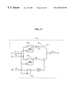
FIG. 27 is a diagram of a phase comparator embodiment.
FIG. 28 is a diagram of a phase comparator response to TxClk duty cycle error.
FIG. 29 is a diagram of an integrator embodiment.
DESCRIPTION OF THE PREFERRED EMBODIMENTS Overview of Invention
This invention makes it possible to take input data of arbitrary phase and re-time it into a second mesochronous clock domain with minimal latency. A block diagram of the preferred embodiment is shown in FIG. 6. It achieves this re-timing via the Synchronizer 400 and the Skip Circuit 401. Each of these distinct circuits and their functions will be described separately, with their operation together described last.
Definitions
There are several terms which aid in the following discussion of the invention.
Rclk: Clock phase-locked to Bus-receive clock (204 in FIG. 5). Duty-cycle corrected
TxClk: Transmit clock as seen on Bus. TxClk lags TClk by 90° (203 in FIG. 5). Not duty-cycle corrected.
Tclk: Clock signal in quadrature with TxClk to facilitate centering of output data around transmit clock. Duty-cycle corrected.
tTR: Time delay from TxClk to RClk divided by the clock cycle-time. This number can also be expressed as a phase value in units of degrees. In systems like FIG. 1, tTR can be directly correlated to the position of a device on the bus.
Skip Circuit: Circuitry which detects the tTR phase value from two clocks, and outputs control signals to a Ladder circuit.
Clock Domain: All circuitry operating from a clock having a particular phase. Circuits whose flip-flops and latches are clocked by clock-X are said to be in the “X-domain”.
Ladder: Timing synchronizer which passes data the Received clock domain (A-domain) and the Transmit clock domain (T-domain)
Ladder0: Circuitry which operates on the falling edge of TClk to receive the RClk-domain data
Ladder1: Circuitry which operates on the rising edge of TClk to receive the RClk- domain data
Skip Value: Output value from Skip Circuit which selects either Ladder0 or Ladder1 of the synchronizer circuit.
RET-FF: Rising-Edge-Triggered Flip-Flop; e.g. a flip-flop which can only change its output on the rising edge of the clock.
FET-FF: Falling-Edge-Triggered Flip-Flop; e.g. a flip-flop which can only change its output on the falling edge of the clock.
Latency domain: A range of tTR values where the output data becomes valid within the same clock cycle.
TCYCLE: The clock cycle time
Overview of Synchronizer 400
The synchronizer 400 of FIG. 10 consists of clock-domain crossing circuitry 402 as well as a re-timing latch 308 and multiplexer 310. The clock-domain crossing circuitry is where the data is adjusted from the RClk domain into the TClk domain. The basic idea behind the clock domain crossing circuitry is straightforward. The input data is guaranteed to be at least one clock-cycle in length. Given input data of this type, if it is fed into both rising and falling-edge triggered flip-flops, at any phase offset one of the flip-flops will be able to correctly sample the input data. This concept is illustrated in FIG. 7. Those skilled in the art will appreciate that edge-triggered flip-flop circuits have required times of input stability called setup & hold times, 226 and 228. In these regions, if the input data to a flip-flop transitions, its output data can be unknown or is an unreliable representation of the input. Conversely, flip-flops have large times when the inputs are allowed to change 225 and 227 and there is no resultant change on the output. By observing the overlap 901 of regions 225 and 227 it can be understood that, given input data with any phase offset, if one RET-FF and one FET-FF are configured as in 402, one of the two flip-flop types (and frequently both of them) will be presented with input data in a valid switching region. Thus, at least one of the two flip-flops will have correctly received the input data, even if the data arrives in the other flip-flop's setup & hold region. The output of FET-FF 307 is then re-timed through latch 308 (see FIG. 10) so that both inputs 216 and 215 to multiplexer 310 have the same timing relationship. In this case the outputs are set to be rising-edge based; in an alternate embodiment, a negative-enable latch could be placed after RET-FF 309 instead and the output from the mux would be falling-edge based. The two data paths that create the inputs to mux 310 are named ladders, as the re-timing function they perform is akin to a “fish-ladder” used to aid fish in swimming-upstream. RET-FF 309 makes up Ladder1 while FET-FF 307 and latch 308 make up Ladder0.
Overview of Skip Circuit 401
The function of the Skip circuit 401 is to generate an output signal which represents the phase skew between two input clocks. It must do this with both precision and accuracy in its determination. A block diagram of the Skip Circuit is shown as FIG. 25. It generates its output via a phase-comparator 405 followed by an integrator 404 and then a latch 403. The phase-comparator compares the input phases by sampling one clock with the other (TxClk is sampled with RClk in one embodiment). If the clocks skew is 0<tTR<0.5 (see FIG. 8) then the phase-comparator generates an output of 0. If the skew is 0.5<tTR<1.0 then the phase-comparator generates an output of 1. To the phase-comparator there is no difference between tTR of 0 and tTR of 1, or between tTR of 0.25 and 1.25, i.e. its behavior is cyclic with phase offset. The phase-comparator is designed with very high gain so its transitions are as close to tTR=0.5 and tTR=1 as possible. To reduce or eliminate the effects of jitter on either clock, the outputs of the comparator are fed into integrator 404. The integrator can be of any conventional form, but contains an input LatchSkip 219 which shuts off integration and ensures full-rail resolution if the integrated value is analog. The integrator serves two purposes. First, it takes the mean of any gaussian jitter (noise) distribution on the input clocks. Secondly, it further narrows any uncertainty in the decision at tTR=0.5 and 1. Lastly, upon assertion of LatchSkip, the skip latch 403 is closed. This becomes important in the application of the Skip Circuit to multi-latency operation, and will be discussed next.
Overview of Synchronizer & Skip Circuit Operation Together, Long-Bus Operation
The synchronization problem becomes one of proper selection between the Ladder0 and Ladder1 via mux 310. This control of mux 310 is accomplished with the Skip Circuit 401. In order to understand the requirements for the Skip Circuit, it is better to first understand the ladder behavior in more detail when used in an arbitrary phase system. Recall that tTR is the phase relationship between TxClk and RClk. In bused systems, such as those in FIG. 1, where clocks travel in the same direction as data, it is often required that the clock traveling with the data have its edge located in the center of the valid data window. This can be accomplished through a variety of techniques usually involving a DLL or PLL. This results in the creation of a clock in quadrature (90° out of phase) with TxClk. We will refer to this clock in quadrature with TxClk as TClk. This clock is needed in order to clock the final output stages which time the output data, with TxClk lagging TClk by 90°.
In FIG. 9 the working range of the ladders is represented with tTR as the X-axis. In order to understand this figure, it is critical to realize that the X-axis is NOT time; it is tTR, the normalized delay difference between TxClk and RClk. With this understanding, it can be seen that the working range 232 of Ladder0 is close to one cycle time, in fact it is equal to TCYCLE−(setup+hold time of the flip-flop 307). It can also be noted that the placement of range 232 begins at (−0.25+hold) and ends at (0.75−setup). The reason that the starting and ending are at −0.25 and 0.75, and not O and 1 is that TClk is used for the ladders. TClk is in quadrature with TxClk which is used to specify tTR.
By observing the first valid operating range of Ladder0 (232) and of Ladder1 (231) in FIG. 9 it can be seen that they overlap. The center of this overlap occurs at precisely tTR=0.5. This, then, is the ideal position for the skip-circuit to change from selection of Ladder0 to selection of ladder1. This location will provide maximum margin from either failure point in either ladder. Next, observe what happens to a ladder as it is pushed beyond its valid operating range. By observing Ladder0 ranges 232 and 233 one can see that just before tTR=0.75, Ladder0 stops working due to the input data passing beyond its valid data window, but it begins functioning again shortly beyond tTR=0.75. In operating range 233 Ladder0's output has moved an entire cycle. That is, output from Ladder0 in range 233 will have one additional cycle of latency relative to its operation in range 232, and is said to be in latency domain 2 (see also FIG. 4). Both ladders, and indeed any synchronization circuitry will exhibit this behavior if the clock skews are pushed beyond their limit. The control of these different latency domains is a key innovation in this invention.
While Ladder0 operates with latency of 1 and 2 in ranges 232 and 233, so does Ladder1 within ranges 231 and 234. Recall that skip 230 is used to seamlessly choose between Ladder0 and Ladder1 at tTR of 0.5. Skip is also used to transition from Ladder1 back to Ladder0 at tTR of 1.0. While the Skip transition at tTR of 0.5 was in no way visible at the output (i.e., the signals 236, 237, and 238 of FIG. 4 are identical), the outputs 236-238 are quite different from output 239. Although 238 and 239 are shown at the same tTR of 1.0, output 238 has skip=1 and when output 239 has skip set back to 0, an additional cycle of latency is added to the output data.
Since the resynchronization circuitry may be used in a system consisting of bused devices as in FIG. 1, it is critical that the devices not change the latency of their output data if they happen to be placed at exactly a latency boundary. The skip latch 403 (FIG. 25) is used to ensure that after a period of initialization, the value of skip is latched and can no longer change. This guarantees that the output latency will not change unless the circuit is reset by re-assertion of LatchSkip 219. After de-assertion of LatchSkip the output data latency can be guaranteed to not change. Fail-safe operation requires no synchronization failure in the synchronizer 400 as well as stable output latency.
This requires, however, that the skip circuit transitions be placed with accuracy and precision, and that the synchronization circuitry have ladders with accurate placement, little deadband and with minimal movement across any voltage and temperature shifts. Any inaccuracy in the skip position or limits of valid ladder operation will limit the potential operating frequency, operating temperature range, or operating voltage if the Skip Circuit chooses a ladder which is pushed beyond its valid operating range. This invention achieves those requirements to provide synchronization at highest operating frequency, over temperature and voltage variations, with the minimum latency possible for fail-safe operation.
Overview of Generation of LatchSkip
The use of the synchronizer and skip circuit in a system requires a control signal to freeze the output of the Skip Circuit 401, called LatchSkip 219 (see FIG. 25). The assertion of this signal causes the skip value to be sampled and held inside latch 403 of the Skip Circuit 401. If the synchronizer is to be used in systems which span more than one clock cycle this function is normally accomplished during initialization, before the output of the synchronization circuit can be used. This avoids the possibility of outputs with different latencies.
There are multiple possible ways of generating LatchSkip 219 to achieve this function. It can simply be asserted through a device reset. In this way when reset is de-asserted the skip output will be latched and the output latency will be fixed unless the device is reset. There are several other ways LatchSkip 219 can be generated. There are frequently initialization packets that are required to setup a device before use. In this case LatchSkip can be generated by a strobe used to receive one of these setup packets. By ensuring that a setup packet asserts LatchSkip 219, the skip output can be guaranteed to be stable before the synchronization circuit is actually used to re-time output data. Alternately, register or mode bits inside a device can also control the strobing of LatchSkip 219. Combining register control with other techniques allows for the flexibility of later skip evaluation and latching without requiring a device reset.
Overview of Multiple Operating Frequencies
In some applications it may be desirable for the system to be able to run at multiple different operating frequencies. This might be done in order to accommodate different power modes, where lower power can be obtained at lower frequencies by disabling some high-power circuitry. In such an application, it may be desirable to maintain multiple values of Skip, one for each operating frequency. In this case multiple skip latches and multiple LatchSkip signals can be used as shown in FIG. 26. In this system initialization would include the evaluation of the phase comparator and integrator at each operating frequency followed by latching into separate skip latches. The appropriate value of skip for the current operating frequency can then be selected by simply using the corresponding latch output.
Detail of Synchronization Circuit 400
The Timing Synchronizer passes data between sequential circuits of two arbitrary-phased mesochronous clock domains. The synchronizer ensures signals are re-timed fail-safe or without metastability and timing glitches, and with minimum latency from circuits of one clock domain to circuits of another clock domain. In addition, when used to time output data transmission on a bus system such as one shown in FIG. 1, the synchronizer times the output data so it arrives within a particular cycle at the destination.
A preferred embodiment of the timing synchronizer is shown in FIG. 10. This circuit consists of Rclk flip-flop 306, Tclk flip- flops 307, 309, Tclk latch 308, and Multiplexer 310. The synchronizer may be partitioned into two signal paths or ladders (Ladder0, Ladder1), each with its own latency characteristics. Data propagates through Ladder0 via nodes 217, 603, 214, 216; Data propagates through Ladder1 via nodes 217, 603, 215. FIG. 11 shows typical outputs at nodes 215 and 216 for tTR=0.0. (Note that TxClk lags TClk by 90° in phase.) At this tTR, the output of Ladder0 is 1 clock cycle later than Ladder1. This result is typical of tTR=−0.25 to 0.25. For the tTR=0.25 to 0.75, the outputs of Ladder0 and Ladder1 are identical and indicate the overlap region of the synchronizer, as shown in FIG. 12. Between tTR=0.75 and 1.25 the synchronizer output (see FIG. 13) has moved to the next cycle akin to the relative ladder output positions in FIG. 11. The behavior is thus cyclic with TCYCLE.
In synchronizer 400 circuit operation, flip-flop 306 samples input Data In 217 every RClk cycle, and holds output 603 valid for one clock cycle (see FIG. 11). At the beginning of each clock cycle, the value at node 603 may transition depending on Dataln 217. During this transition period, data cannot be reliably sampled by edge triggered flip-flops. Because TClk flip- flop 307 and 309 sample data on the falling and rising edges of TClk respectively, at least one of these two flip-flops is guaranteed to sample data from node 603 when it is not changing. This is required for fail-safe data resynchronization. For most ranges of tTR neither of the Tclk sampling edges are near node 603's data transition, and both Ladders will capture the correct value. However, over varying values of tTR, output from Ladder0 at node 216 may be zero or one cycle later than the output from Ladder1 at node 215.
Each ladder operates over a particular tTR range of operation without encountering problems with metastability. The range of valid tTR with which each ladder operates is determined by the range where a particular TClk sampling edge 212 falls within Valid Data window 603. For example, if the tTR value is 0.25 (in reference to FIG. 12, RClk 21 1, Datain 217, and Valid Data 603 should be shifted earlier by 90°), the sampling rising edge of TClk aligns with the tail portion of valid data 603. For cases where tTR is greater than 0.25, RClk 211, Datain 217, and Valid Data 603 shifts later in time, until the sampling rising edge of TClk aligns with the beginning portion of valid data 603 at tTR=1.25. The center of each ladder's operating range occurs when the center 613 of the Valid Data window 603 aligns with the ladder's sampling TClk edge. The center of the overlap between the two ladders occurs when Valid Data Center 613 is equidistant from the two sampling TClk edges as in FIG. 12.
Region (a) of FIG. 14 shows the operating ranges of the two ladders in the Synchronizer circuits versus tTR phase values. (In the context of a device on a bus/channel such as that shown in FIG. 1, a particular tTR value may be interpreted as an indicator of the position on the bus.) As discussed in the previous paragraph, Ladder0 ideally operates for tTR range of −0.25 to 0.75 (see FIG. 14(a)/622). Similarly, Ladder1 ideally operates for tTR range of 0.25 to 1.25 (see FIG. 14(a)/622). The overlap window between ladders 621 and 622 in indicates the region where both Ladder1 and Ladder0 outputs are the same. Ladder0 623 is similar to Ladder0 621. However, its output is shifted 1 Cycle later in time. The ends of each ladder shown in region (a) of FIG. 14 indicate tTR operation ranges beyond which the particular ladder is unreliable.
Proper operation should avoid the ends of the ladders. Therefore, even with ideal components, Ladder0 621 may be used for the entire range except at tTR=−0.25, and tTR=0.75; Ladder1 622 may be used for the entire range except at tTR=0.25, and tTR=1.25. In the overlap region, either Ladder0 or Ladder1 may be used. For optimum fail-safe operation, the multiplexer 310 (FIG. 10) should select another ladder before the end of the current ladder is reached. Therefore, the optimal mux select 0 to 1 transition should be at tTR=0.5, and the optimal mux select 1 to 0transition should be at tTR=1.0. This placement of mux select values over tTR leaves equal amounts of margin for timing errors of non-ideal ladders. These errors will be discussed in the next section. An important point to note is that the input clocks to the synchronizer are periodic, and thus synchronizer characteristics repeat in tTR space.
Practical implementation of the synchronizer yields ladder circuits which do not fully correspond to region (a) of FIG. 14. Each ladder in region (a) of FIG. 14 spans the theoretical full clock cycle of tTR range, resulting in a half cycle of ladder overlap. However, in practice, the synchronizer has less overlap margin due to circuit imperfections. These imperfections take the form of shifting ladder alignment as shown in region (b) of FIG. 14, and narrowing the ladders as shown in FIG. 15. Thus, the ladders each span less than 1 clock cycle, the overlap region spans less than half a clock cycle, and the ladder positions may be shifted from the ideal case.
Analysis of the clock domain crossing indicates the sources of these errors. An examination of the signal flow between flip- flops 306 and 307 in FIG. 10 best illustrates some of the timing errors. In the ideal case, all flip-flops have zero setup-or-hold requirements, and no clock-to-data-out delay. In our example, RClk flip-flop 306 will have no clk-to-data-out delay as shown by waveform 702 (see FIG. 16). Waveform 704, 705 shows zero setup and hold for TClk flip-flop 307. The ideal circuit elements in FIG. 16 will result in a one clock cycle long ladder span with symmetric overlap region between Ladder0 and Ladder1 at both ends of the span.
Actual flip-flops do not perform as well. FIG. 17 and FIG. 18 show the waveforms of flip-flops 306 and 307 (shown in FIG. 10) for a typical and slow performance conditions respectively. The varying circuit performance is due to varying integrated circuit transistor processes, power supply voltage and operating temperature of practical systems. Ladder position shifts are caused by clock-to-data-out delay variation of flip-flop 306 and setup/hold variations of flip-flop 307. These variations are equivalent to shifting Rclk and Tclk (thus effective tTR) in the ideal case shown in FIG. 16. Any mismatched clock buffering of Tclk and Rclk within the integrated circuit contributes additional ladder shifts.
Besides ladder shifts, another source of error is narrowing of the ladder's valid operating region. This narrowing is caused by the data transition time 717 of circuit 306, and setup 714/724 and hold 715/725 of flip-flop 307. Within this period, capture of signal 603 is unreliable and may lead to wrong data. Clock jitter also adds to ladder narrowing by injecting phase shifts to the clocks. Clock jitter adds to the uncertainty region caused by set-up, hold and clock-to-data-out 718/728 variations. Similar analysis applies to the clock domain boundary between flip- flops 306 and 309.
The circuit implementation of the synchronizer addresses the aforementioned Ladder shifts and shrinkage for maximum timing margin over varying process, voltage, and temperature conditions. A partial circuit schematic of one implementation is shown in FIG. 19. This circuit addresses the sources of Ladder shifts and shrinkage with delay compensation and faster circuit performance. To minimize ladder shifting, a precharged sense amp is used for the second stage flip-flops. The clocked sense-amp latching delay varies approximately with the clock-to-data-out delay of the previous stage latch. So in slower transistor performance conditions, the clocked sense-amp will delay its sampling point to compensate for the added clock-to-data-out delay at nodes 806 and Ladder17. The use of differential signals 806, 807 instead of single-ended signal 603 increases the sense-amp gain, and lowers the setup and hold of flip- flops 307, 309.
The Synchronizer circuit shown in FIG. 10 uses the falling edge of RClk 831/830 and the rising and falling edges of TClk 808/809 to generate overlapping Ladder0 and Ladder1. This configuration generates rising-edge triggered outputs. In an alternate embodiment for a falling-edge driven sequential logic system, we could reverse the polarity of the sampling edge of all sequential elements, and achieve proper operation. Alternatively, the synchronizer can use the rising and falling edges of RClk with one sampling edge of Tclk, an embodiment of which is shown in FIG. 20. The basic premise used to achieve clock domain crossing is to use circuits clocked with different phases of one clock domain to pass data into another domain. The end results are overlapping ladders similar to those shown in FIG. 14.
Another embodiment of the timing synchronizer is shown in FIG. 21, and consists of four overlapping ladders 961/971, 962/972, 963/973 and 964/974. The resultant ladder ranges are shown versus tTR value in FIG. 22. We should note that the ideal overlap between each ladder is ¾ TCYCLE. This allows substantially more margin for errors in ladder shifts, narrowing, and placements of Mux 979 select controls. This embodiment divides the synchronization problem into four separate ladders. If this concept is taken further, an arbitrary number of ladders (of two or greater) may be used with the ideal overlap margin being: T overlap = T cycle num ( ladders ) - 1 num ( ladders )
Figure US06473439-20021029-M00002
The above equation shows diminishing increase of overlap margin with an increased number of ladders. Also, an increasing number of ladders requires a larger number of mux select controls.
A different embodiment of the synchronizer is shown in FIG. 23. This synchronizer realigns the data with the use of a “blended” clock lntClk 1005. The blended clock has a phase which is halfway between RClk and TClk as shown in FIG. 24. The synchronizer includes three sequentially coupled latches 1003,1006, 1009 that are clocked by RClk 1002, lntClk 1005 and TClk 1008, respectively.
Node 1004 represents RClk valid data, which moves later in phase relative to TClk as tTR increases. This synchronizer circuit preserves the output delay of Data Out/1010 relative to TClk over the entire tTR range of 0 to 1. At tTR=0, the input clocks Rclk and TClk are aligned, and the synchronizer has a three clock cycle delay through the circuit. As tTR increases, and RClk/1 002 and Valid Data/1004 lags TClk, the Latency of the synchronizer circuit decreases to compensate for the increased delay of RClk relative to TClk. Therefore, Data Out 1010 is captured by the same TClk edge even as the RClk valid data 1004 is delayed by up to one clock cycle.
The inputs required for this synchronizer are RClk 1002, IntClk 1005, TClk 1008, and RClk-domain Data In 1001. An external multiplexer select generator is not required. In a preferred embodiment, IntClk 1005 is generated by a phase interpolator or mixer circuit 1007.
Detail of Skip Circuit 401
The Skip Circuit 401 (see FIG. 25) is made up of a phase comparator 405, an integrator 404, and a latch 403. The purpose of the Skip Circuit is to generate a very accurate measurement of tTR with minimal-width uncertainty regions. It also provides the capability to latch the output value after initialization, eliminating the possibility of multiple operating latencies if tTR is near a latency-domain boundary.
A preferred embodiment of the phase-comparator in FIG. 27 is used in order to provide an accurate measurement with minimum uncertainty. It contains high-gain narrow-uncertainty-window data receivers of the same type that are used to sample bus data. In the preferred embodiment these are used in conjunction with a DLL or PLL which has aligned RClk so any receiver setup+hold time has been removed. Using a data receiver to sample the external signal TxClk has two advantages over sampling an internal clock. First, it gives the most accurate measurement of bus position as internal clocks can be skewed by clock recovery circuits for a number of reasons. Second, it provides the lowest-jitter source of transmit-domain phase information available. Any clock recovered with a DLL or PLL (e.g. TClk) will necessarily have higher jitter than at the input clock.
In the ideal case, a simple FET (falling-edge-triggered) data receiver could be used to generate the phase-comparator output. However, since clocks traveling at high-speed can undergo duty-cycle distortion, a single-data receiver used in this fashion could incorrectly determine the value of tTR if it was sampling a duty-cycle distorted clock while being clocked by a duty-cycle corrected clock (see FIG. 28). In the case where RClk locks to the falling-edge of its corresponding bus clock, a TxClk duty-cycle 248 less than 50% would cause a FET phase-comparator to falsely put the TR=0.5 transition at a tTR greater than 0.5. Similarly, if TxClk duty-cycle was greater than 50% 249, the comparator would erroneously put the tTR=0.5 transition at a tTR lower than 0.5. The use of an additional data-receiver 408 in FIG. 27 which is clocked on the rising edge of RClk together with an inverter 412 avoids this problem. Near tTR of 0.5 where a single falling edge triggered receiver would be providing false information due the time shifted rising edge of TxClk, the rising edge of RClk will be near the falling edge of TxClk. By choosing whichever data receiver is closest to sampling the falling-edge of TxClk, using multiplexer 410 and flip-flop 411, the phase comparator can tolerate a non-50% duty-cycle on TxClk. This can be more easily understood by observing the different characteristics of waveforms 248, 249 and 251 at the time of both the RClk rising edge 253 and the RClk falling edge 252. The preferred embodiment of FIG. 27 thus uses flip-flop 411 to make a rough comparison of TClk and Rclk and generate a control signal, SelEven 247, that is used by multiplexer 410 to choose FET receiver 409 for −0.25<tTR<0.25 and RET receiver 408 for 0.25<tTR<0.75. The exact tTR positioning of SelEven is not critical, as in most cases outputs 245 and 246 are identical. The preferred embodiment thus can compare the phase of potentially duty-cycle distorted clocks to duty-cycle corrected clocks and maintain a high degree of accuracy in phase-comparison by only measuring to the falling-edge. In an alternate embodiment, the inverter could be moved and the multiplexer control switched to compare to the rising edge of TxClk with the same effect.
An alternate embodiment of phase-comparator 405 uses a Quadrature Phase Detector to compare RClk and TClk, the Quadrature Phase Detector having output which indicates when the clocks are in quadrature. This eliminates the need for the use of a clock which is in quadrature to TClk, and allows for the combined system to only use two clocks.
The Skip Circuit integrator 404 consists of a standard integrator, which serves to narrow the uncertainty window created by a jitter distribution (such as a gaussian distribution). Any clock will have a certain amount of random noise which shows up as a distribution of phase. Using an integrator on the output of the phase-comparator ensures that signal 243's transition will be closest to the mean-point of the jitter distributions of both TxClk 220 and RClk 211, while at any single-point in time the raw phase-comparator output 242 could be the result of comparison to an extreme of the clock jitter distributions.
An integrator 404 preferred embodiment shown in FIG. 29 is an analog integrator with steered up and down current sources 416 and 435 into capacitors 417 and 436 which create a differential voltage on output nodes 243 and 270. The steering of these currents is controlled by switches driven by the comparator output 242. In a preferred embodiment, the integrator is allowed to run for at least 40 cycles after the clocks settle, in order to ensure an adequate gaussian distribution of the clock inputs. After this time, the LatchSkip 219 signal is asserted and de-asserted to both the integrator and the skip latch 403 turning off integration. If the integrator is analog, this signal also asserts a high-gain sense-amp 415. LatchSkip 219 also closes the skip latch 403 so the Skip Circuit output will not change unless LatchSkip 219 is re-asserted.
Detail of Combined Operation of Synchronizer 400 and Skin Circuit 401
The Synchronizer 400 and Skip Circuit 401 make up a synchronization system. Both elements are required in the preferred embodiment in order to properly synchronize data between two mesochronous clock domains. This invention allows for 1) high operating frequency and then 2) low latency while maintaining fail-safe operation.
In order to achieve fail-safe operation, the Synchronizer must not fail to both properly pass and re-time the incoming data. The most significant failure mechanism is if the improper ladder for the current operating conditions (tTR, Voltage, temperature) is used. This can come about due to error sources which this invention minimizes. The multiple possible error sources result in an equation which limits the cycle-time of the system. Possible sources of error include:
1. Error in the Absolute Placement of the Ladder Range
This can result in the Skip Circuit choosing the ladder which is closer to its failure point. It can also result in less than optimal ladder overlap regions.
2. Shifting of the Ladders due to Chances in Operating Environment (e.g. Vdd. temp)
Ladder shift during operation must be minimized so that the functional ladder range does not pass the current operating tTR.
3. Ladder Deadband
Ladder deadband caused by flip-flop setup & hold uncertainty regions directly subtracts from the timing budget for data resynchronization.
Clock jitter can also serve to shift the ladder ranges.
4. Skip Accuracy
Error in the absolute placement of the skip transition can result in choosing the ladder which is closer to its failure point, similar to #1.
5. Skip Uncertainty
A large uncertainty-window in skip means that it is possible that skip will choose the ladder closer to its failure point.
The preferred embodiment of both circuits minimizes each of the possible error sources to provide the maximum fail-safe operating frequency. The sources of error listed above lead to an equation which must be maintained in order to have fail-safe operation. This equation represents the minimum cycle-time limit of the system. T Cycle 4 ( T Setup + T Hold 4 ) + Error Ladder + Error Skip + Movement Ladder
Figure US06473439-20021029-M00003
The preferred embodiment places the Skip transition at tTR=1. As previously mentioned, the placement of this transition sets the boundary of the first latency domain. In another embodiment, RClk or TxClk/TClk may be shifted earlier or later by a constant time or phase delay so the first latency domain boundary occurs at a tTR other than 1. As both the Synchronizer 400 and the Skip Circuit 401 use RClk as the starting reference both circuits will shift together. All latency domains remain 1 cycle wide, and so all boundary ends will move as well.
An alternate embodiment of this nature that requires no delay elements receives the R-domain data 217 of FIG. 10 with a rising-edge-triggered flip flop instead of falling-edge-triggered flip-flop 306 and the value of skip is inverted from that in the normal embodiment. By making these two changes the circuit moves the first latency domain range to −0.5<tTR<0.5 and the second range to 0.5<tTR<1.5. This may be done if a coarse adjustment of the domain start and end points is desired.
Thus the combination of the Synchronizer and Skip circuit provide high frequency fail-safe synchronization for mesochronous systems such as that of FIG. 1. Arbitrary phase delays are possible while fail-safe latency is minimized and output latency is kept constant despite changes in the circuit's operating point.
Multiple Operating Frequencies
To accommodate switching between multiple operating frequencies without requiring re-evaluation of skip an alternate embodiment of the Skip circuit 430 can be used as shown in FIG. 26. In this embodiment the single Skip Latch 403 of FIG. 25 has been replaced by multiple skip latches 431-433. In addition, the single LatchSkip signal 219 of FIG. 25 has been replaced by LatchSkip_F1 to LatchSkip_Fn 260-265. There is one latch and one LatchSkip signal for each desired operating frequency.
The operation of this embodiment is as follows. Upon initialization, each of the desired operating frequencies is selected and initialized. During this initialization, after stabilization of the clocks at the new frequency the appropriate LatchSkip_Fx signal is asserted using one of the techniques described previously. After all frequencies have been initialized the correct value for Skip at each desired frequency is stored in the respective skip latches 431-433. The device can then simply select the appropriate Skip value depending on its current operating frequency without having to wait for the Skip Circuit to reevaluate. A multiplexing circuit can connect a selected skip latch to skip input 213 of FIG. 10.

Claims (22)

What is claimed is:
1. A synchronization circuit for synchronizing data between receive and transmit mesochronous clocks, comprising:
a receive clock domain circuit for providing the data clocked by the receive clock;
a first latching circuit, coupled to an output of the receive clock domain circuit, for latching the data on a first edge of the transmit clock; wherein the receive clock and transmit clock are mesochronous;
a second latching circuit, coupled to the receive clock domain circuit in parallel with the first latching circuit, for latching the data on a second edge of the-transmit clock;
a multiplexing circuit, having inputs coupled to outputs of the first and second latching circuits; and
a phase measurement circuit, configured to measure a phase difference between the receive and transmit clocks and to provide a select signal to the multiplexer in accordance with the phase difference.
2. The synchronization circuit of claim 1, wherein
the phase measurement circuit is configured to determine a phase difference between the receive clock and a clock in quadrature with the transmit clock; the phase measurement circuit including a phase comparator coupled to receive the receive clock and the clock in quadrature with the transmit clock, and an integrator coupled to an output of the phase comparator; and
the synchronization circuit including a latch coupled to an output of the phase measurement circuit for latching an output signal after an initialization period.
3. The synchronization circuit of claim 1, wherein the phase measurement circuit determines a phase difference between the receive clock and a clock in quadrature with the transmit clock.
4. The synchronization circuit of claim 1 wherein the phase measurement circuit comprises:
a phase comparator coupled to receive the receive clock and a clock in quadrature with the transmit clock; and
an integrator coupled to an output of the phase comparator.
5. The synchronization circuit of claim 1 further comprising a latch coupled to an output of the phase measurement circuit for latching an output signal after an initialization period.
6. The synchronization circuit of claim 1 wherein the latching circuits are flip-flops.
7. The synchronization circuit of claim 1 further comprising a third latching circuit, connected between an output of the first latching circuit and the multiplexer, for re-timing the output of the first latching circuit to the second edge of the transmit clock signal.
8. The synchronization circuit of claim 1 further comprising a select signal latch connected to a select input of the multiplexer.
9. The synchronization circuit of claim 8, further comprising a plurality of select signal latches, for storing different select signals corresponding to different clock frequencies.
10. The synchronization circuit of claim 1 wherein the first and second latching circuits each include a precharged sense amplifier.
11. A synchronous memory bus system comprising:
a data bus having a first end and a second end;
a clock source generating a clock signal;
a clock line carrying the clock signal, the clock line having
a first clock line segment extending from the first end of the data bus to a turnaround near the second end of the data bus, and
a second clock line segment extending from the turnaround to the first end of the data bus;
a first device coupled to the data bus for transmitting data to a second device, including synchronization circuitry that receives a first transmit clock from one of the first and second clock line segments, a receive clock from the other one of the first and second clock line segments, and a second transmit clock in quadrature with the first transmit clock, wherein the receive clock and first transmit clock are mesochronous, the synchronization circuitry comprising:
a receive clock domain circuit for providing the data clocked by the receive clock;
a first latching circuit, coupled to an output of the receive clock domain circuit, for latching the data on a first edge of the second transmit clock;
a second latching circuit, in parallel with the first latching circuit, for latching the data on a second edge of the second transmit clock;
a multiplexing circuit, having inputs coupled to outputs of the first and second latching circuits; and
a phase measurement circuit, configured to measure a phase difference between the receive clock and first transmit clock and to provide a select signal to the multiplexer in accordance with the phase difference.
12. A method for synchronizing data between receive and transmit mesochronous clocks, comprising the steps of:
providing data clocked by a receive clock from a receive clock domain;
latching the data in a first latching circuit on a first edge of a transmit clock;
latching the data in a second latching circuit on a second edge of the transmit clock;
wherein the receive clock and transmit clock are mesochronous and the second latching circuit is coupled to receive the data in parallel with the first latching circuit;
measuring a phase difference between the receive and transmit clocks and providing a select signal in accordance with the phase difference; and
selecting between the first and second latching circuit based on the select signal.
13. The method of claim 12 wherein the step of measuring a phase difference comprises determining a phase difference between the receive clock and a clock in quadrature with the transmit clock.
14. The method of claim 12 wherein the step of measuring a phase difference comprises the steps of:
comparing the receive clock and a clock in quadrature with the transmit clock; and
integrating a result of the comparing step.
15. The method of claim 12 further comprising the step of latching the select signal after an initialization or calibration sequence.
16. The method of claim 12, further comprising latching an output of the first latching circuit with on the second edge of the transmit clock signal so as to re-time the output of the first latching circuit to the second edge of the transmit clock signal.
17. A synchronization circuit for synchronizing data between receive and transmit mesochronous clocks, comprising:
a first receive clock domain circuit for providing the data clocked by a first edge of the receive clock;
a second receive clock domain circuit for providing the data clocked by a second edge of the receive clock;
two latching circuits, each coupled to an output of a respective of said first and second receive clock domain circuits, for latching the data on an edge of the transmit clock; wherein the receive clock and transmit clock are mesochronous and the first receive clock domain circuit and the second receive clock domain circuit are connected in parallel between a source of the data and the two latching circuits;
a multiplexing circuit, having inputs coupled to outputs of the two latching circuits; and
a phase measurement circuit, configured to measure a phase difference between the receive and transmit clocks and to provide a selection signal to the multiplexer in accordance with the phase differences.
18. The synchronization circuit of claim 17 wherein the phase measurement circuit determines a phase difference between the receive clock and a clock in quadrature with the transmit clock.
19. The synchronization circuit of claim 17 wherein the phase measurement circuit comprises:
a phase comparator coupled to receive the receive clock and the clock in quadrature with the transmit clock; and
an integrator coupled to an output of the phase comparator.
20. The synchronization circuit of claim 17 further comprising a latch coupled to an output of the phase measurement circuit for latching an output signal after an initialization period.
21. A synchronization circuit for synchronizing data between receive and transmit mesochronous clocks, comprising:
a receive clock domain circuit for providing the data clocked by the receive clock;
an intermediate clock domain circuit latching the output of the receive clock domain circuit on an edge of an intermediate clock, wherein the intermediate clock is a phase-interpolated waveform of the receive and transmit clocks and the receive clock and transmit clock are mesochronous; and
a transmit clock domain circuit, coupled to an output of the intermediate clock domain circuit, for latching the data on an edge of the transmit clock.
22. The circuit of claim 21 further comprising:
a phase interpolator or mixer for generating the intermediate clock from the receive and transmit clocks.
US09/169,372 1997-10-10 1998-10-09 Method and apparatus for fail-safe resynchronization with minimum latency Expired - Fee Related US6473439B1 (en)

Priority Applications (3)

Application Number Priority Date Filing Date Title
US09/169,372 US6473439B1 (en) 1997-10-10 1998-10-09 Method and apparatus for fail-safe resynchronization with minimum latency
US10/282,531 US6949958B2 (en) 1997-10-10 2002-10-28 Phase comparator capable of tolerating a non-50% duty-cycle clocks
US11/237,276 US7288973B2 (en) 1997-10-10 2005-09-27 Method and apparatus for fail-safe resynchronization with minimum latency

Applications Claiming Priority (2)

Application Number Priority Date Filing Date Title
US6150597P 1997-10-10 1997-10-10
US09/169,372 US6473439B1 (en) 1997-10-10 1998-10-09 Method and apparatus for fail-safe resynchronization with minimum latency

Related Child Applications (1)

Application Number Title Priority Date Filing Date
US10/282,531 Continuation US6949958B2 (en) 1997-10-10 2002-10-28 Phase comparator capable of tolerating a non-50% duty-cycle clocks

Publications (1)

Publication Number Publication Date
US6473439B1 true US6473439B1 (en) 2002-10-29

Family

ID=22036219

Family Applications (3)

Application Number Title Priority Date Filing Date
US09/169,372 Expired - Fee Related US6473439B1 (en) 1997-10-10 1998-10-09 Method and apparatus for fail-safe resynchronization with minimum latency
US10/282,531 Expired - Fee Related US6949958B2 (en) 1997-10-10 2002-10-28 Phase comparator capable of tolerating a non-50% duty-cycle clocks
US11/237,276 Expired - Fee Related US7288973B2 (en) 1997-10-10 2005-09-27 Method and apparatus for fail-safe resynchronization with minimum latency

Family Applications After (2)

Application Number Title Priority Date Filing Date
US10/282,531 Expired - Fee Related US6949958B2 (en) 1997-10-10 2002-10-28 Phase comparator capable of tolerating a non-50% duty-cycle clocks
US11/237,276 Expired - Fee Related US7288973B2 (en) 1997-10-10 2005-09-27 Method and apparatus for fail-safe resynchronization with minimum latency

Country Status (8)

Country Link
US (3) US6473439B1 (en)
EP (1) EP1031093B1 (en)
JP (1) JP4484359B2 (en)
KR (1) KR100603687B1 (en)
AT (1) ATE232317T1 (en)
AU (1) AU9798698A (en)
DE (1) DE69811262T2 (en)
WO (1) WO1999019806A1 (en)

Cited By (50)

* Cited by examiner, † Cited by third party
Publication number Priority date Publication date Assignee Title
US20020017403A1 (en) * 2000-06-09 2002-02-14 Olivier Phely Track drive device for all terrain vehicle
US20020099999A1 (en) * 2000-11-30 2002-07-25 Thomas Wagner Data reception method
US20020194518A1 (en) * 2001-06-06 2002-12-19 Chang Kun-Yung Ken Apparatus and method for generating a skip signal
US20030053489A1 (en) * 1997-10-10 2003-03-20 Rambus, Inc. Method and apparatus for fail-safe resynchronization with minimum latency
US20040082429A1 (en) * 2002-10-29 2004-04-29 Madhusudan Raghavan Multi-speed transmission mechanisms with three planetary gearsets and clutch input
US6799280B1 (en) * 2000-01-04 2004-09-28 Advanced Micro Devices, Inc. System and method for synchronizing data transfer from one domain to another by selecting output data from either a first or second storage device
US20040223565A1 (en) * 2003-05-09 2004-11-11 Adkisson Richard W. System and method for maintaining a stable synchronization state in a programmable clock synchronizer
US20050041683A1 (en) * 2003-08-21 2005-02-24 Rambus, Inc. Periodic interface calibration for high speed communication
US20050097484A1 (en) * 2003-10-30 2005-05-05 Atrenta Inc. Method for clock synchronization validation in integrated circuit design
US20050163203A1 (en) * 2004-01-28 2005-07-28 Rambus, Inc. Communication channel calibration for drift conditions
EP1571531A1 (en) * 2004-03-05 2005-09-07 Thales Method and apparatus for sampling digital data in a synchronous transmission, keeping binary integrity
US20050210308A1 (en) * 2004-03-17 2005-09-22 Rambus, Inc. Drift tracking feedback for communication channels
US20050229127A1 (en) * 2004-04-02 2005-10-13 Stmicroelectronics Limited Method for verifying adequate synchronisation of signals that cross clock environments and system
US20050265437A1 (en) * 2004-05-28 2005-12-01 Rambus, Inc. Communication channel calibration with nonvolatile parameter store for recovery
US20050276322A1 (en) * 2004-06-14 2005-12-15 Rambus, Inc. Hybrid wired and wireless chip-to-chip communications
US20060062327A1 (en) * 2004-09-17 2006-03-23 Rambus, Inc. Method and apparatus for data recovery
US7061406B1 (en) 2005-01-21 2006-06-13 Rambus, Inc. Low power, DC-balanced serial link transmitter
US20060165185A1 (en) * 2005-01-21 2006-07-27 Rambus, Inc. Communication system with low power, DC-balanced serial link
US20060165195A1 (en) * 2005-01-21 2006-07-27 Rambus, Inc. A low power, dc-balanced serial link
US20060279342A1 (en) * 2005-06-14 2006-12-14 Micron Technology, Inc. DLL measure initialization circuit for high frequency operation
US20070071032A1 (en) * 2004-01-28 2007-03-29 Rambu Inc. Adaptive-allocation of i/o bandwidth using a configurable interconnect topology
US7275171B2 (en) 2003-05-22 2007-09-25 Rambus Inc. Method and apparatus for programmable sampling clock edge selection
US20070230549A1 (en) * 2004-01-28 2007-10-04 Rambus Inc. Periodic calibration for communication channels by drift tracking
US20080008281A1 (en) * 2006-07-06 2008-01-10 Nischal Abrol Clock compensation techniques for audio decoding
US7359407B1 (en) * 2002-08-27 2008-04-15 Cypress Semiconductor Corp. Data interface that is configurable into separate modes of operation for sub-bit de-skewing of parallel-fed data signals
US20080109672A1 (en) * 2006-11-08 2008-05-08 Sicortex, Inc Large scale computing system with multi-lane mesochronous data transfers among computer nodes
US7516029B2 (en) 2004-06-09 2009-04-07 Rambus, Inc. Communication channel calibration using feedback
US20100039147A1 (en) * 2007-06-07 2010-02-18 Micron Technology, Inc. Semiconductor devices with signal synchronization circuits
US20100083027A1 (en) * 2008-09-30 2010-04-01 Mosaid Technologies Incorporated Serial-connected memory system with output delay adjustment
US20100083028A1 (en) * 2008-09-30 2010-04-01 Mosaid Technologies Incorporated Serial-connected memory system with duty cycle correction
US20110213908A1 (en) * 2009-12-23 2011-09-01 Bennett Jon C R Configurable interconnection system
US8112655B2 (en) * 2005-04-21 2012-02-07 Violin Memory, Inc. Mesosynchronous data bus apparatus and method of data transmission
US8422568B2 (en) 2004-01-28 2013-04-16 Rambus Inc. Communication channel calibration for drift conditions
US20130136195A1 (en) * 2011-11-29 2013-05-30 Advanced Micro Devices, Inc. System and method of data communications between electronic devices
US8726064B2 (en) 2005-04-21 2014-05-13 Violin Memory Inc. Interconnection system
CN103838296A (en) * 2012-11-20 2014-06-04 辉达公司 Variation-tolerant periodic synchronizer
US20140347108A1 (en) * 2012-03-26 2014-11-27 Rambus Inc. Method and apparatus for source-synchronous signaling
TWI488437B (en) * 2011-08-15 2015-06-11 Mediatek Singapore Pte Ltd Integrated circuit device, synchronisation module, electronic device and method therefor
US9213487B2 (en) 2013-10-16 2015-12-15 Qualcomm Incorporated Receiver architecture for memory reads
US20150364173A1 (en) * 2014-06-13 2015-12-17 Samsung Electronics Co., Ltd. Storage device including nonvolatile memory and memory controller and operating method of retiming circuit interfacing communication between nonvolatile memory and memory controller
US9563292B2 (en) 2013-04-22 2017-02-07 Sharp Kabushiki Kaisha Stylus pen, touch panel system and electronic device
US9582449B2 (en) 2005-04-21 2017-02-28 Violin Memory, Inc. Interconnection system
US20170205465A1 (en) * 2015-04-04 2017-07-20 Nvidia Corporation Granular dynamic test systems and methods
US10095263B1 (en) * 2015-12-15 2018-10-09 Marvell International Ltd. Apparatus and method for calibrating signal synchronization
US10176861B2 (en) 2005-04-21 2019-01-08 Violin Systems Llc RAIDed memory system management
US10281524B2 (en) 2015-10-27 2019-05-07 Nvidia Corporation Test partition external input/output interface control for test partitions in a semiconductor
US10965441B1 (en) * 2019-10-10 2021-03-30 Rohde & Schwarz Gmbh & Co. Kg Frame trigger recreation method and frame trigger recreator
US11622005B2 (en) * 2019-03-27 2023-04-04 Boe Technology Group Co., Ltd. Internet of Things system, central control device, application device and communication methods
US11677391B1 (en) * 2021-01-28 2023-06-13 Rambus Inc. Low-power multi-domain synchronizer
US11829640B2 (en) 2020-10-27 2023-11-28 Rambus Inc. Asynchronous arbitration across clock domains for register writes in an integrated circuit chip

Families Citing this family (45)

* Cited by examiner, † Cited by third party
Publication number Priority date Publication date Assignee Title
WO2001095552A2 (en) * 2000-06-02 2001-12-13 Connectcom Microsystems, Inc. High frequency network receiver
DE60132425T2 (en) * 2000-10-11 2009-02-26 Ntt Electronics Corp. PHASE COMPARISON CIRCUIT
US7194056B2 (en) 2001-06-25 2007-03-20 Rambus Inc. Determining phase relationships using digital phase values
US6920540B2 (en) 2001-10-22 2005-07-19 Rambus Inc. Timing calibration apparatus and method for a memory device signaling system
TWI235917B (en) 2002-04-15 2005-07-11 Via Tech Inc High speed data transmitter and transmission method thereof
CN100421096C (en) * 2002-05-08 2008-09-24 威盛电子股份有限公司 High-speed data transmission equipment and its transmission method
US7149874B2 (en) * 2002-08-16 2006-12-12 Micron Technology, Inc. Memory hub bypass circuit and method
JP3704709B2 (en) 2002-10-02 2005-10-12 日本電気株式会社 Data resynchronizer
US7231009B2 (en) * 2003-02-19 2007-06-12 Silicon Image, Inc. Data synchronization across an asynchronous boundary using, for example, multi-phase clocks
US7133991B2 (en) * 2003-08-20 2006-11-07 Micron Technology, Inc. Method and system for capturing and bypassing memory transactions in a hub-based memory system
US7136958B2 (en) * 2003-08-28 2006-11-14 Micron Technology, Inc. Multiple processor system and method including multiple memory hub modules
US7120743B2 (en) * 2003-10-20 2006-10-10 Micron Technology, Inc. Arbitration system and method for memory responses in a hub-based memory system
KR20050076202A (en) * 2004-01-20 2005-07-26 삼성전자주식회사 Dleay signal generator circuit and memory system including the same
US7788451B2 (en) 2004-02-05 2010-08-31 Micron Technology, Inc. Apparatus and method for data bypass for a bi-directional data bus in a hub-based memory sub-system
US7412574B2 (en) * 2004-02-05 2008-08-12 Micron Technology, Inc. System and method for arbitration of memory responses in a hub-based memory system
US7257683B2 (en) * 2004-03-24 2007-08-14 Micron Technology, Inc. Memory arbitration system and method having an arbitration packet protocol
US7447240B2 (en) * 2004-03-29 2008-11-04 Micron Technology, Inc. Method and system for synchronizing communications links in a hub-based memory system
US6980042B2 (en) 2004-04-05 2005-12-27 Micron Technology, Inc. Delay line synchronizer apparatus and method
US7535985B2 (en) 2004-04-26 2009-05-19 Panasonic Corporation Resynchronization circuit
US20050259692A1 (en) * 2004-05-19 2005-11-24 Zerbe Jared L Crosstalk minimization in serial link systems
US7363419B2 (en) 2004-05-28 2008-04-22 Micron Technology, Inc. Method and system for terminating write commands in a hub-based memory system
US20060098770A1 (en) * 2004-11-09 2006-05-11 Harper William F Synchronizer for passing data from a first system to a second system
US7653167B2 (en) * 2006-09-07 2010-01-26 Intel Corporation Phase deglitch circuit for phase interpolator for high-speed serial I/O applications
EP1901474B1 (en) * 2006-09-13 2011-11-30 Stmicroelectronics Sa System for synchronizing modules in an integrated circuit in mesochronous clock domains
EP1936857A1 (en) 2006-12-22 2008-06-25 Stmicroelectronics Sa System for transmitting data between transmitter and receiver modules on a channel provided with a flow control link
US7836324B2 (en) * 2007-02-09 2010-11-16 Apple Inc. Oversampling-based scheme for synchronous interface communication
US7908574B2 (en) * 2007-05-09 2011-03-15 Synopsys, Inc. Techniques for use with automated circuit design and simulations
US7984400B2 (en) * 2007-05-09 2011-07-19 Synopsys, Inc. Techniques for use with automated circuit design and simulations
US8756557B2 (en) * 2007-05-09 2014-06-17 Synopsys, Inc. Techniques for use with automated circuit design and simulations
US7904859B2 (en) * 2007-05-09 2011-03-08 Synopsys, Inc. Method and apparatus for determining a phase relationship between asynchronous clock signals
KR100929824B1 (en) * 2008-05-06 2009-12-07 주식회사 하이닉스반도체 Semiconductor device
JP5276928B2 (en) * 2008-08-29 2013-08-28 株式会社日立製作所 Phase comparison circuit for signal regeneration circuit and optical communication apparatus provided with phase comparison circuit for signal regeneration circuit
EP2427184B1 (en) 2009-05-08 2017-08-30 3M Innovative Properties Company Oral care method and kit
WO2011008356A2 (en) * 2009-06-30 2011-01-20 Rambus Inc. Techniques for adjusting clock signals to compensate for noise
US8261121B2 (en) * 2009-12-24 2012-09-04 Nvidia Corporation Command latency reduction and command bandwidth maintenance in a memory circuit
US8707080B1 (en) * 2011-07-12 2014-04-22 Emc Corporation Simple circular asynchronous clock domain crossing technique for digital data
CN103247323B (en) * 2012-02-07 2016-05-04 北京兆易创新科技股份有限公司 A kind of serial interface flash memory
CN103247325B (en) * 2012-02-07 2017-03-01 北京兆易创新科技股份有限公司 A kind of serial i/O Interface flash memory
TWI449338B (en) * 2012-04-18 2014-08-11 Univ Nat Sun Yat Sen Peak detector with digital calibration
KR101950320B1 (en) * 2012-06-29 2019-02-20 에스케이하이닉스 주식회사 Phase detection circuit and synchronization circuit using the same
US9541990B2 (en) 2015-04-21 2017-01-10 Cypress Semiconductor Corporation Asynchronous transceiver for on-vehicle electronic device
US10623174B1 (en) 2018-12-12 2020-04-14 Xilinx, Inc. Low latency data transfer technique for mesochronous divided clocks
CN111797043B (en) * 2019-04-08 2022-04-26 达发科技(苏州)有限公司 Cross-clock domain system
US10924091B2 (en) * 2019-07-02 2021-02-16 Stmicroelectronics International N.V. Immediate fail detect clock domain crossing synchronizer
KR20220166775A (en) * 2020-04-09 2022-12-19 주식회사 아도반테스토 Circuitry for transferring data from one clock domain to another clock domain

Citations (8)

* Cited by examiner, † Cited by third party
Publication number Priority date Publication date Assignee Title
WO1993018463A1 (en) 1992-03-06 1993-09-16 Rambus, Inc. Method and circuitry for minimizing clock-data skew in a bus system
US5504742A (en) * 1992-10-20 1996-04-02 Fujitsu Limited Broadband ISDN remote multiplexer
US5509038A (en) * 1994-04-06 1996-04-16 Hal Computer Systems, Inc. Multi-path data synchronizer system and method
US5551050A (en) 1989-12-20 1996-08-27 Texas Instruments Incorporated System and method using synchronized processors to perform real time internal monitoring of a data processing device
US5550875A (en) 1994-12-29 1996-08-27 Unisys Corporation Apparatus and method for residual error clock skew bound, and clocking therewith
WO1996041267A1 (en) 1995-06-07 1996-12-19 Ast Research, Inc. Delay reduction in transfer of buffered data between two mutually asynchronous buses
US5652530A (en) 1995-09-29 1997-07-29 Intel Corporation Method and apparatus for reducing clock-data skew by clock shifting
WO1999019806A1 (en) 1997-10-10 1999-04-22 Rambus Incorporated Method and apparatus for fail-safe resynchronization with minimum latency

Family Cites Families (18)

* Cited by examiner, † Cited by third party
Publication number Priority date Publication date Assignee Title
US4819081A (en) * 1987-09-03 1989-04-04 Intel Corporation Phase comparator for extending capture range
JPH04262618A (en) * 1991-02-18 1992-09-18 Advantest Corp Phase detector
US5757868A (en) * 1994-02-16 1998-05-26 Motorola, Inc. Digital phase detector with integrated phase detection
US5646519A (en) * 1995-06-07 1997-07-08 Symmetricom, Inc. Digital phase detector employing a digitally controllable delay line
JP2806863B2 (en) * 1996-02-27 1998-09-30 日本電気エンジニアリング株式会社 Bit synchronization circuit
US5799048A (en) * 1996-04-17 1998-08-25 Sun Microsystems, Inc. Phase detector for clock synchronization and recovery
JP3467975B2 (en) * 1996-06-27 2003-11-17 安藤電気株式会社 Phase detection circuit
US6205191B1 (en) * 1997-07-21 2001-03-20 Rambus Inc. Method and apparatus for synchronizing a control signal
US6008680A (en) * 1997-08-27 1999-12-28 Lsi Logic Corporation Continuously adjustable delay-locked loop
TW388795B (en) * 1997-12-24 2000-05-01 Via Tech Inc Auxiliary device and method for signal testing
US6150889A (en) * 1998-08-03 2000-11-21 Motorola, Inc. Circuit and method for minimizing recovery time
US6334163B1 (en) * 1999-03-05 2001-12-25 International Business Machines Corp. Elastic interface apparatus and method therefor
US6100722A (en) * 1999-07-28 2000-08-08 Cypress Semiconductor Corp. Phase detector with extended linear range
US6172540B1 (en) * 1999-08-16 2001-01-09 Intel Corporation Apparatus for fast logic transfer of data across asynchronous clock domains
US6799280B1 (en) * 2000-01-04 2004-09-28 Advanced Micro Devices, Inc. System and method for synchronizing data transfer from one domain to another by selecting output data from either a first or second storage device
US6987823B1 (en) * 2000-02-07 2006-01-17 Rambus Inc. System and method for aligning internal transmit and receive clocks
US6798259B2 (en) * 2001-08-03 2004-09-28 Micron Technology, Inc. System and method to improve the efficiency of synchronous mirror delays and delay locked loops
US6614314B2 (en) * 2001-12-03 2003-09-02 Gennum Corporation Non-linear phase detector

Patent Citations (9)

* Cited by examiner, † Cited by third party
Publication number Priority date Publication date Assignee Title
US5551050A (en) 1989-12-20 1996-08-27 Texas Instruments Incorporated System and method using synchronized processors to perform real time internal monitoring of a data processing device
WO1993018463A1 (en) 1992-03-06 1993-09-16 Rambus, Inc. Method and circuitry for minimizing clock-data skew in a bus system
US5432823A (en) * 1992-03-06 1995-07-11 Rambus, Inc. Method and circuitry for minimizing clock-data skew in a bus system
US5504742A (en) * 1992-10-20 1996-04-02 Fujitsu Limited Broadband ISDN remote multiplexer
US5509038A (en) * 1994-04-06 1996-04-16 Hal Computer Systems, Inc. Multi-path data synchronizer system and method
US5550875A (en) 1994-12-29 1996-08-27 Unisys Corporation Apparatus and method for residual error clock skew bound, and clocking therewith
WO1996041267A1 (en) 1995-06-07 1996-12-19 Ast Research, Inc. Delay reduction in transfer of buffered data between two mutually asynchronous buses
US5652530A (en) 1995-09-29 1997-07-29 Intel Corporation Method and apparatus for reducing clock-data skew by clock shifting
WO1999019806A1 (en) 1997-10-10 1999-04-22 Rambus Incorporated Method and apparatus for fail-safe resynchronization with minimum latency

Non-Patent Citations (2)

* Cited by examiner, † Cited by third party
Title
"Low Latency Plesiochronous Data Retiming"; Larry R. Dennison et al.; Artificial Intelligence Laboratory, MIT; (date unknown).
"Synchronization in Digital System Design"; David G. Messerschmitt; IEEE Journal on Selected Areas in Cmmunications, vol. 8, No. 8, Oct., 1990.

Cited By (139)

* Cited by examiner, † Cited by third party
Publication number Priority date Publication date Assignee Title
US7288973B2 (en) 1997-10-10 2007-10-30 Rambus Inc. Method and apparatus for fail-safe resynchronization with minimum latency
US20060022724A1 (en) * 1997-10-10 2006-02-02 Zerbe Jared L Method and apparatus for fail-safe resynchronization with minimum latency
US6949958B2 (en) * 1997-10-10 2005-09-27 Rambus Inc. Phase comparator capable of tolerating a non-50% duty-cycle clocks
US20030053489A1 (en) * 1997-10-10 2003-03-20 Rambus, Inc. Method and apparatus for fail-safe resynchronization with minimum latency
US6799280B1 (en) * 2000-01-04 2004-09-28 Advanced Micro Devices, Inc. System and method for synchronizing data transfer from one domain to another by selecting output data from either a first or second storage device
US20020017403A1 (en) * 2000-06-09 2002-02-14 Olivier Phely Track drive device for all terrain vehicle
US6859885B2 (en) * 2000-11-30 2005-02-22 Robert Bosch Gmbh Data reception method
US20020099999A1 (en) * 2000-11-30 2002-07-25 Thomas Wagner Data reception method
US20020194518A1 (en) * 2001-06-06 2002-12-19 Chang Kun-Yung Ken Apparatus and method for generating a skip signal
US7359407B1 (en) * 2002-08-27 2008-04-15 Cypress Semiconductor Corp. Data interface that is configurable into separate modes of operation for sub-bit de-skewing of parallel-fed data signals
US20040082429A1 (en) * 2002-10-29 2004-04-29 Madhusudan Raghavan Multi-speed transmission mechanisms with three planetary gearsets and clutch input
US7239681B2 (en) * 2003-05-09 2007-07-03 Hewlett-Packard Development Company, L.P. System and method for maintaining a stable synchronization state in a programmable clock synchronizer
US20040223565A1 (en) * 2003-05-09 2004-11-11 Adkisson Richard W. System and method for maintaining a stable synchronization state in a programmable clock synchronizer
US7275171B2 (en) 2003-05-22 2007-09-25 Rambus Inc. Method and apparatus for programmable sampling clock edge selection
US20060159113A1 (en) * 2003-08-21 2006-07-20 Rambus, Inc. Periodic interface calibration for high speed communication
US7072355B2 (en) 2003-08-21 2006-07-04 Rambus, Inc. Periodic interface calibration for high speed communication
US20050041683A1 (en) * 2003-08-21 2005-02-24 Rambus, Inc. Periodic interface calibration for high speed communication
US7506292B2 (en) 2003-10-30 2009-03-17 Atrenta, Inc. Method for clock synchronization validation in integrated circuit design
US20050097484A1 (en) * 2003-10-30 2005-05-05 Atrenta Inc. Method for clock synchronization validation in integrated circuit design
US7073146B2 (en) * 2003-10-30 2006-07-04 Atrenta Inc. Method for clock synchronization validation in integrated circuit design
US20060150043A1 (en) * 2003-10-30 2006-07-06 Atrenta Inc. Method for clock synchronization validation in integrated circuit design
US10305674B2 (en) 2004-01-28 2019-05-28 Rambus Inc. Communication channel calibration for drift conditions
US7400671B2 (en) 2004-01-28 2008-07-15 Rambus Inc. Periodic calibration for communication channels by drift tracking
US10673582B2 (en) 2004-01-28 2020-06-02 Rambus Inc. Communication channel calibration for drift conditions
US10819447B2 (en) 2004-01-28 2020-10-27 Rambus Inc. Periodic calibration for communication channels by drift tracking
US11108510B2 (en) 2004-01-28 2021-08-31 Rambus Inc. Communication channel calibration for drift conditions
US11258522B2 (en) 2004-01-28 2022-02-22 Rambus Inc. Periodic calibration for communication channels by drift tracking
US10320496B2 (en) 2004-01-28 2019-06-11 Rambus Inc. Periodic calibration for communication channels by drift tracking
US20110219162A1 (en) * 2004-01-28 2011-09-08 Rambus Inc. Adaptive-Allocation Of I/O Bandwidth Using A Configurable Interconnect Topology
US9667359B2 (en) 2004-01-28 2017-05-30 Rambus Inc. Periodic calibration for communication channels by drift tracking
US9667406B2 (en) 2004-01-28 2017-05-30 Rambus Inc. Communication channel calibration for drift conditions
US7095789B2 (en) 2004-01-28 2006-08-22 Rambus, Inc. Communication channel calibration for drift conditions
US9628257B2 (en) 2004-01-28 2017-04-18 Rambus Inc. Communication channel calibration for drift conditions
US20060291574A1 (en) * 2004-01-28 2006-12-28 Rambus Inc. Communication channel calibration for drift conditions
US11552748B2 (en) 2004-01-28 2023-01-10 Rambus Inc. Communication channel calibration for drift conditions
US9160466B2 (en) 2004-01-28 2015-10-13 Rambus Inc. Periodic calibration for communication channels by drift tracking
US20070071032A1 (en) * 2004-01-28 2007-03-29 Rambu Inc. Adaptive-allocation of i/o bandwidth using a configurable interconnect topology
US9042504B2 (en) 2004-01-28 2015-05-26 Rambus Inc. Communication channel calibration for drift conditions
US11664907B2 (en) 2004-01-28 2023-05-30 Rambus Inc. Periodic calibration for communication channels by drift tracking
US8929424B2 (en) 2004-01-28 2015-01-06 Rambus Inc. Periodic calibration for communication channels by drift tracking
US8073009B2 (en) 2004-01-28 2011-12-06 Rambus Inc. Adaptive allocation of I/O bandwidth using a configurable interconnect topology
US20070230549A1 (en) * 2004-01-28 2007-10-04 Rambus Inc. Periodic calibration for communication channels by drift tracking
US8144792B2 (en) 2004-01-28 2012-03-27 Rambus Inc. Communication channel calibration for drift conditions
US20070280393A1 (en) * 2004-01-28 2007-12-06 Rambus Inc. Communication channel calibration for drift conditions
US8693556B2 (en) 2004-01-28 2014-04-08 Rambus Inc. Communication channel calibration for drift conditions
US8644419B2 (en) 2004-01-28 2014-02-04 Rambus Inc. Periodic calibration for communication channels by drift tracking
US20050163203A1 (en) * 2004-01-28 2005-07-28 Rambus, Inc. Communication channel calibration for drift conditions
US8422568B2 (en) 2004-01-28 2013-04-16 Rambus Inc. Communication channel calibration for drift conditions
US7400670B2 (en) 2004-01-28 2008-07-15 Rambus, Inc. Periodic calibration for communication channels by drift tracking
US10523344B2 (en) 2004-01-28 2019-12-31 Rambus Inc. Periodic calibration for communication channels by drift tracking
US7415073B2 (en) 2004-01-28 2008-08-19 Rambus, Inc. Communication channel calibration for drift conditions
US7420990B2 (en) 2004-01-28 2008-09-02 Rambus Inc. Adaptive-allocation of I/O bandwidth using a configurable interconnect topology
US20080276020A1 (en) * 2004-01-28 2008-11-06 Rambus Inc. Adaptive-Allocation Of I/O Bandwidth Using A Configurable Interconnect Topology
US8149874B2 (en) 2004-01-28 2012-04-03 Rambus Inc. Adaptive-allocation of I/O bandwidth using a configurable interconnect topology
EP1571531A1 (en) * 2004-03-05 2005-09-07 Thales Method and apparatus for sampling digital data in a synchronous transmission, keeping binary integrity
US7509514B2 (en) 2004-03-05 2009-03-24 Thales Method and device for the sampling of digital data in synchronous transmission, with maintenance of binary integrity
US20050198549A1 (en) * 2004-03-05 2005-09-08 Thales Method and device for the sampling of digital data in synchronous transmission, with maintenance of binary integrity
FR2867334A1 (en) * 2004-03-05 2005-09-09 Thales Sa METHOD AND APPARATUS FOR SAMPLING DIGITAL DATA IN SYNCHRONOUS TRANSMISSION WITH BINARY INTEGRITY RETAINING
US7159136B2 (en) 2004-03-17 2007-01-02 Rambus, Inc. Drift tracking feedback for communication channels
US7526664B2 (en) 2004-03-17 2009-04-28 Rambus, Inc. Drift tracking feedback for communication channels
US8504863B2 (en) 2004-03-17 2013-08-06 Rambus Inc. Drift tracking feedback for communication channels
US7640448B2 (en) 2004-03-17 2009-12-29 Rambus, Inc. Drift tracking feedback for communication channels
US10503201B2 (en) 2004-03-17 2019-12-10 Rambus Inc. Drift tracking feedback for communication channels
US20100058100A1 (en) * 2004-03-17 2010-03-04 Rambus, Inc. Drift tracking feedback for communication channels
US11669124B2 (en) 2004-03-17 2023-06-06 Rambus Inc. Drift tracking feedback for communication channels
US20050210308A1 (en) * 2004-03-17 2005-09-22 Rambus, Inc. Drift tracking feedback for communication channels
US9710011B2 (en) 2004-03-17 2017-07-18 Rambus Inc. Drift tracking feedback for communication channels
US11327524B2 (en) 2004-03-17 2022-05-10 Rambus Inc. Drift tracking feedback for communication channels
US6961862B2 (en) 2004-03-17 2005-11-01 Rambus, Inc. Drift tracking feedback for communication channels
US20050229127A1 (en) * 2004-04-02 2005-10-13 Stmicroelectronics Limited Method for verifying adequate synchronisation of signals that cross clock environments and system
US7159199B2 (en) * 2004-04-02 2007-01-02 Stmicroelectronics Limited Method for verifying adequate synchronization of signals that cross clock environments and system
US20050265437A1 (en) * 2004-05-28 2005-12-01 Rambus, Inc. Communication channel calibration with nonvolatile parameter store for recovery
US8488686B2 (en) 2004-05-28 2013-07-16 Rambus Inc. Communication channel calibration with nonvolatile parameter store for recovery
US20110235727A1 (en) * 2004-05-28 2011-09-29 Rambus, Inc. Communication channel calibration with nonvolatile parameter store for recovery
US7978754B2 (en) 2004-05-28 2011-07-12 Rambus Inc. Communication channel calibration with nonvolatile parameter store for recovery
US9735898B2 (en) 2004-06-09 2017-08-15 Rambus Inc. Communication channel calibration using feedback
US7516029B2 (en) 2004-06-09 2009-04-07 Rambus, Inc. Communication channel calibration using feedback
US8121803B2 (en) 2004-06-09 2012-02-21 Rambus, Inc. Communication channel calibration using feedback
US10439740B2 (en) 2004-06-09 2019-10-08 Rambus Inc. Communication channel calibration using feedback
US11128388B2 (en) 2004-06-09 2021-09-21 Rambus Inc. Communication channel calibration using feedback
US20090132741A1 (en) * 2004-06-09 2009-05-21 Rambus, Inc. Communication channel calibration using feedback
US9172521B2 (en) 2004-06-09 2015-10-27 Rambus Inc. Communication channel calibration using feedback
US7535958B2 (en) 2004-06-14 2009-05-19 Rambus, Inc. Hybrid wired and wireless chip-to-chip communications
US20050276322A1 (en) * 2004-06-14 2005-12-15 Rambus, Inc. Hybrid wired and wireless chip-to-chip communications
US7489739B2 (en) 2004-09-17 2009-02-10 Rambus, Inc. Method and apparatus for data recovery
US8233567B2 (en) 2004-09-17 2012-07-31 Rambus Inc. Method and apparatus for data recovery
US20060062327A1 (en) * 2004-09-17 2006-03-23 Rambus, Inc. Method and apparatus for data recovery
US20090110115A1 (en) * 2004-09-17 2009-04-30 Rambus, Inc. Method and apparatus for data recovery
US20060164264A1 (en) * 2005-01-21 2006-07-27 Rambus, Inc. Low power, DC-balanced serial link transmitter
US7061406B1 (en) 2005-01-21 2006-06-13 Rambus, Inc. Low power, DC-balanced serial link transmitter
US7199728B2 (en) 2005-01-21 2007-04-03 Rambus, Inc. Communication system with low power, DC-balanced serial link
US20060165195A1 (en) * 2005-01-21 2006-07-27 Rambus, Inc. A low power, dc-balanced serial link
US20060165185A1 (en) * 2005-01-21 2006-07-27 Rambus, Inc. Communication system with low power, DC-balanced serial link
US7088270B1 (en) 2005-01-21 2006-08-08 Rambus, Inc. Low power, DC-balanced serial link
US7268706B2 (en) 2005-01-21 2007-09-11 Rambus, Inc. Low power, DC-balanced serial link transmitter
US10176861B2 (en) 2005-04-21 2019-01-08 Violin Systems Llc RAIDed memory system management
US8112655B2 (en) * 2005-04-21 2012-02-07 Violin Memory, Inc. Mesosynchronous data bus apparatus and method of data transmission
US9582449B2 (en) 2005-04-21 2017-02-28 Violin Memory, Inc. Interconnection system
US8726064B2 (en) 2005-04-21 2014-05-13 Violin Memory Inc. Interconnection system
US10417159B2 (en) 2005-04-21 2019-09-17 Violin Systems Llc Interconnection system
US20060279342A1 (en) * 2005-06-14 2006-12-14 Micron Technology, Inc. DLL measure initialization circuit for high frequency operation
US7332950B2 (en) 2005-06-14 2008-02-19 Micron Technology, Inc. DLL measure initialization circuit for high frequency operation
US20080008281A1 (en) * 2006-07-06 2008-01-10 Nischal Abrol Clock compensation techniques for audio decoding
US9420332B2 (en) * 2006-07-06 2016-08-16 Qualcomm Incorporated Clock compensation techniques for audio decoding
US20080109672A1 (en) * 2006-11-08 2008-05-08 Sicortex, Inc Large scale computing system with multi-lane mesochronous data transfers among computer nodes
US8134391B2 (en) * 2007-06-07 2012-03-13 Micron Technology, Inc. Semiconductor devices with signal synchronization circuits
US20100039147A1 (en) * 2007-06-07 2010-02-18 Micron Technology, Inc. Semiconductor devices with signal synchronization circuits
US8161313B2 (en) 2008-09-30 2012-04-17 Mosaid Technologies Incorporated Serial-connected memory system with duty cycle correction
US20100083027A1 (en) * 2008-09-30 2010-04-01 Mosaid Technologies Incorporated Serial-connected memory system with output delay adjustment
US20100083028A1 (en) * 2008-09-30 2010-04-01 Mosaid Technologies Incorporated Serial-connected memory system with duty cycle correction
US8181056B2 (en) 2008-09-30 2012-05-15 Mosaid Technologies Incorporated Serial-connected memory system with output delay adjustment
US20110213908A1 (en) * 2009-12-23 2011-09-01 Bennett Jon C R Configurable interconnection system
US9465756B2 (en) 2009-12-23 2016-10-11 Violin Memory Inc. Configurable interconnection system
TWI488437B (en) * 2011-08-15 2015-06-11 Mediatek Singapore Pte Ltd Integrated circuit device, synchronisation module, electronic device and method therefor
US8782458B2 (en) * 2011-11-29 2014-07-15 Advanced Micro Devices, Inc. System and method of data communications between electronic devices
US20130136195A1 (en) * 2011-11-29 2013-05-30 Advanced Micro Devices, Inc. System and method of data communications between electronic devices
US20140347108A1 (en) * 2012-03-26 2014-11-27 Rambus Inc. Method and apparatus for source-synchronous signaling
US10840920B2 (en) 2012-03-26 2020-11-17 Rambus Inc. Method and apparatus for source-synchronous signaling
US10211841B2 (en) 2012-03-26 2019-02-19 Rambus Inc. Method and apparatus for source-synchronous signaling
US10541693B2 (en) 2012-03-26 2020-01-21 Rambus Inc. Method and apparatus for source-synchronous signaling
US9748960B2 (en) * 2012-03-26 2017-08-29 Rambus Inc. Method and apparatus for source-synchronous signaling
CN103838296A (en) * 2012-11-20 2014-06-04 辉达公司 Variation-tolerant periodic synchronizer
US9563292B2 (en) 2013-04-22 2017-02-07 Sharp Kabushiki Kaisha Stylus pen, touch panel system and electronic device
US9213487B2 (en) 2013-10-16 2015-12-15 Qualcomm Incorporated Receiver architecture for memory reads
US20150364173A1 (en) * 2014-06-13 2015-12-17 Samsung Electronics Co., Ltd. Storage device including nonvolatile memory and memory controller and operating method of retiming circuit interfacing communication between nonvolatile memory and memory controller
US9601171B2 (en) * 2014-06-13 2017-03-21 Samsung Electronics Co., Ltd. Storage device including nonvolatile memory and memory controller and operating method of retiming circuit interfacing communication between nonvolatile memory and memory controller
US20170205465A1 (en) * 2015-04-04 2017-07-20 Nvidia Corporation Granular dynamic test systems and methods
US10481203B2 (en) * 2015-04-04 2019-11-19 Nvidia Corporation Granular dynamic test systems and methods
US10444280B2 (en) 2015-10-27 2019-10-15 Nvidia Corporation Independent test partition clock coordination across multiple test partitions
US10317463B2 (en) 2015-10-27 2019-06-11 Nvidia Corporation Scan system interface (SSI) module
US10281524B2 (en) 2015-10-27 2019-05-07 Nvidia Corporation Test partition external input/output interface control for test partitions in a semiconductor
US10451676B2 (en) 2015-10-27 2019-10-22 Nvidia Corporation Method and system for dynamic standard test access (DSTA) for a logic block reuse
US10473720B2 (en) 2015-10-27 2019-11-12 Nvidia Corporation Dynamic independent test partition clock
US10545189B2 (en) 2015-10-27 2020-01-28 Nvidia Corporation Granular dynamic test systems and methods
US10095263B1 (en) * 2015-12-15 2018-10-09 Marvell International Ltd. Apparatus and method for calibrating signal synchronization
US11622005B2 (en) * 2019-03-27 2023-04-04 Boe Technology Group Co., Ltd. Internet of Things system, central control device, application device and communication methods
US10965441B1 (en) * 2019-10-10 2021-03-30 Rohde & Schwarz Gmbh & Co. Kg Frame trigger recreation method and frame trigger recreator
US11829640B2 (en) 2020-10-27 2023-11-28 Rambus Inc. Asynchronous arbitration across clock domains for register writes in an integrated circuit chip
US11677391B1 (en) * 2021-01-28 2023-06-13 Rambus Inc. Low-power multi-domain synchronizer

Also Published As

Publication number Publication date
WO1999019806A1 (en) 1999-04-22
US20060022724A1 (en) 2006-02-02
JP4484359B2 (en) 2010-06-16
DE69811262D1 (en) 2003-03-13
EP1031093A1 (en) 2000-08-30
KR20010031036A (en) 2001-04-16
AU9798698A (en) 1999-05-03
JP2001520417A (en) 2001-10-30
US6949958B2 (en) 2005-09-27
EP1031093B1 (en) 2003-02-05
US7288973B2 (en) 2007-10-30
KR100603687B1 (en) 2006-07-20
US20030053489A1 (en) 2003-03-20
ATE232317T1 (en) 2003-02-15
DE69811262T2 (en) 2003-11-27

Similar Documents

Publication Publication Date Title
US6473439B1 (en) Method and apparatus for fail-safe resynchronization with minimum latency
US7765074B2 (en) Circuit, apparatus and method for capturing a representation of a waveform from a clock-data recovery (CDR) unit
US7974375B2 (en) Linear phase detector and clock/data recovery circuit thereof
JP4065234B2 (en) Data recovery device for synchronous chip-chip system
US7571340B2 (en) Eliminating receiver clock drift caused by voltage and temperature change in a high-speed I/O system that uses a forwarded clock
US11061432B2 (en) Data handoff between two clock domains sharing a fundamental beat
US7256627B1 (en) Alignment of local transmit clock to synchronous data transfer clock having programmable transfer rate
US5689530A (en) Data recovery circuit with large retime margin
JP5093216B2 (en) Oscillator circuit
US20040030513A1 (en) Transition insensitive timing recovery method and apparatus
US6795514B2 (en) Integrated data clock extractor
US7519844B2 (en) PVT drift compensation
US7583118B2 (en) Delay locked loop circuit
US7430141B2 (en) Method and apparatus for memory data deskewing
US9813069B1 (en) Half-rate bang-bang phase detector
US7231009B2 (en) Data synchronization across an asynchronous boundary using, for example, multi-phase clocks
US6604203B1 (en) Arrangement and method for self-synchronization data to a local clock
US8718215B2 (en) Method and apparatus for deskewing data transmissions
Brandon Synchronizing multiple AD9852 DDS-based synthesizers
Khawshe et al. A 2.4 Gbps-4.8 Gbps XDR-DRAM I/O (XIO) Link

Legal Events

Date Code Title Description
AS Assignment

Owner name: RAMBUS, INC., CALIFORNIA

Free format text: ASSIGNMENT OF ASSIGNORS INTEREST;ASSIGNOR:DAVIS, PAUL G.;REEL/FRAME:009795/0604

Effective date: 19990126

Owner name: RAMBUS, INC., CALIFORNIA

Free format text: ASSIGNMENT OF ASSIGNORS INTEREST;ASSIGNORS:LEVAN ZERBE, JARED 12091998;CHING, MICHAEL TAK-KEI;ABHYANKAR, ABHIJIT M.;AND OTHERS;REEL/FRAME:009795/0610;SIGNING DATES FROM 19981209 TO 19981222

FPAY Fee payment

Year of fee payment: 4

FPAY Fee payment

Year of fee payment: 8

REMI Maintenance fee reminder mailed
LAPS Lapse for failure to pay maintenance fees
STCH Information on status: patent discontinuation

Free format text: PATENT EXPIRED DUE TO NONPAYMENT OF MAINTENANCE FEES UNDER 37 CFR 1.362

FP Lapsed due to failure to pay maintenance fee

Effective date: 20141029