US6478039B2 - Side rail assembly for canopy - Google Patents
Side rail assembly for canopy Download PDFInfo
- Publication number
- US6478039B2 US6478039B2 US09/811,651 US81165101A US6478039B2 US 6478039 B2 US6478039 B2 US 6478039B2 US 81165101 A US81165101 A US 81165101A US 6478039 B2 US6478039 B2 US 6478039B2
- Authority
- US
- United States
- Prior art keywords
- side rail
- assembly according
- fixture
- hinged member
- socket
- Prior art date
- Legal status (The legal status is an assumption and is not a legal conclusion. Google has not performed a legal analysis and makes no representation as to the accuracy of the status listed.)
- Expired - Fee Related, expires
Links
Images


Classifications
-
- E—FIXED CONSTRUCTIONS
- E04—BUILDING
- E04H—BUILDINGS OR LIKE STRUCTURES FOR PARTICULAR PURPOSES; SWIMMING OR SPLASH BATHS OR POOLS; MASTS; FENCING; TENTS OR CANOPIES, IN GENERAL
- E04H15/00—Tents or canopies, in general
- E04H15/32—Parts, components, construction details, accessories, interior equipment, specially adapted for tents, e.g. guy-line equipment, skirts, thresholds
- E04H15/34—Supporting means, e.g. frames
- E04H15/44—Supporting means, e.g. frames collapsible, e.g. breakdown type
- E04H15/48—Supporting means, e.g. frames collapsible, e.g. breakdown type foldable, i.e. having pivoted or hinged means
- E04H15/50—Supporting means, e.g. frames collapsible, e.g. breakdown type foldable, i.e. having pivoted or hinged means lazy-tongs type
-
- Y—GENERAL TAGGING OF NEW TECHNOLOGICAL DEVELOPMENTS; GENERAL TAGGING OF CROSS-SECTIONAL TECHNOLOGIES SPANNING OVER SEVERAL SECTIONS OF THE IPC; TECHNICAL SUBJECTS COVERED BY FORMER USPC CROSS-REFERENCE ART COLLECTIONS [XRACs] AND DIGESTS
- Y10—TECHNICAL SUBJECTS COVERED BY FORMER USPC
- Y10S—TECHNICAL SUBJECTS COVERED BY FORMER USPC CROSS-REFERENCE ART COLLECTIONS [XRACs] AND DIGESTS
- Y10S135/00—Tent, canopy, umbrella, or cane
- Y10S135/909—Fitting
-
- Y—GENERAL TAGGING OF NEW TECHNOLOGICAL DEVELOPMENTS; GENERAL TAGGING OF CROSS-SECTIONAL TECHNOLOGIES SPANNING OVER SEVERAL SECTIONS OF THE IPC; TECHNICAL SUBJECTS COVERED BY FORMER USPC CROSS-REFERENCE ART COLLECTIONS [XRACs] AND DIGESTS
- Y10—TECHNICAL SUBJECTS COVERED BY FORMER USPC
- Y10T—TECHNICAL SUBJECTS COVERED BY FORMER US CLASSIFICATION
- Y10T403/00—Joints and connections
- Y10T403/34—Branched
- Y10T403/341—Three or more radiating members
- Y10T403/345—Coplanar
- Y10T403/346—Additional rod held by encompassing means
-
- Y—GENERAL TAGGING OF NEW TECHNOLOGICAL DEVELOPMENTS; GENERAL TAGGING OF CROSS-SECTIONAL TECHNOLOGIES SPANNING OVER SEVERAL SECTIONS OF THE IPC; TECHNICAL SUBJECTS COVERED BY FORMER USPC CROSS-REFERENCE ART COLLECTIONS [XRACs] AND DIGESTS
- Y10—TECHNICAL SUBJECTS COVERED BY FORMER USPC
- Y10T—TECHNICAL SUBJECTS COVERED BY FORMER US CLASSIFICATION
- Y10T403/00—Joints and connections
- Y10T403/44—Three or more members connected at single locus
-
- Y—GENERAL TAGGING OF NEW TECHNOLOGICAL DEVELOPMENTS; GENERAL TAGGING OF CROSS-SECTIONAL TECHNOLOGIES SPANNING OVER SEVERAL SECTIONS OF THE IPC; TECHNICAL SUBJECTS COVERED BY FORMER USPC CROSS-REFERENCE ART COLLECTIONS [XRACs] AND DIGESTS
- Y10—TECHNICAL SUBJECTS COVERED BY FORMER USPC
- Y10T—TECHNICAL SUBJECTS COVERED BY FORMER US CLASSIFICATION
- Y10T403/00—Joints and connections
- Y10T403/46—Rod end to transverse side of member
Definitions
- the present invention relates to a side rail for a canopy, particularly a side rail for a collapsible and portable canopy. More particularly, the present invention relates to an improved side rail assembly which is simply and cost-effectively constructed, easy to install, and which adds torsional stability to a canopy on which it is installed.
- Conventional side rails are known for installation on collapsible and portable canopies.
- the conventional side rails can be difficult to install and complicated in structure.
- conventional side rails can be flimsy and without a great deal of stability.
- conventional side rails can break or fall off the canopy structure in the event of torsional stress in which, for example, one or more uprights of the canopy supporting the side rails move in opposite directions.
- complicated means may need to be provided in order to prevent the side rail from slipping down the upright, or in order to fix the side rail at a desired height on the upright.
- the present invention provides a side rail assembly for a canopy having a plurality of uprights.
- the side rail assembly according to the invention comprises a side rail having two ends, and a fixture.
- the fixture is configured to be fixed at one end of the side rail, and defines a central hollow dimensioned to fit snugly around one of the plurality of uprights.
- the fixture further has a socket for receiving one end of the side rail, and hinged member.
- the hinged member defines one wall portion of the central hollow.
- the fixture is slidable around the upright when the hinged member is in an open position and fixture is fixed around the upright when the hinged member is in a closed position.
- a locking member is provided which is disposed to lock the hinged member in the closed position.
- the fixture further comprises a fixing member extending into the central hollow and insertable into a corresponding receptacle of the upright in order to make the fixture fixable at a desired vertical position on the upright.
- a wedge portion of the hinged member defines a portion of the central hollow.
- a slot dimensioned to receive the wedge portion of the hinged member when the hinged member is in the closed position, is also provided on the fixture.
- the fixing member can be provided in addition to the wedge portion, in a further embodiment. Also, the wedge portion can be provided in an embodiment without the fixing member.
- the hinged portion also defines a wall of the socket so that, when the hinged portion is in the open position, the end of the side rail is laterally insertable into the socket.
- the central hollow is preferably rectangular, or square in cross section. This is preferably so, because the uprights of canopies have more torsional stability and bending strength when fashioned to be either rectangular or square in cross section.
- the fixture may further comprise a second socket disposed at an angle to the first socket and dimensioned to receive an end of a side rail.
- This second socket may be useful when the side rail assembly is used to affix a side rail to more than one contiguous side of a canopy structure, such as when a side rail is required for a front and side or a front and two sides, or any other desired combination of contiguous sides.
- the second socket may be disposed at an angle of 90° to the first socket.
- the end of the side rail may comprise a transverse hole
- a hinged member may also comprise a hole disputed to be alignable with the transverse hole of the end of the side rail.
- the locking member is a bolt
- the bolt may pass through the hole of the hinged member and through the transverse hole of the side rail and thus the dual objective of locking the hinged member in the closed position and stabilizing the side rail in the socket can be achieved.
- the locking member is a bolt
- a hex nut threadable with the bolt can be counter-sunk into one of the hinged member or a portion of the fixture opposite the hinged member in the socket.
- FIG. 1 is a perspective drawing of a conventional canopy having side rail assemblies according to the present invention.
- FIG. 2 is a perspective cut-away drawing showing one embodiment of the fixture according to the present invention fixed to an upright of a canopy.
- FIG. 3 is a top plan view of one fixture of the side rail assembly according to the present invention.
- FIGS. 4 and 5 are side plan views of one embodiment of the fixture according to the present invention in which the locking member holds the hinged member in the closed position and fixes the side rail in the socket.
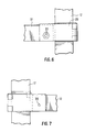
- FIGS. 6 and 7 are further side plan views of the side rail assembly fixing the side rail to one of the uprights.
- FIG. 1 shows a conventional portable canopy 10 in perspective. Attached to the canopy 10 are side rail assemblies 11 .
- the side rail assemblies 11 comprise fixtures 13 and side rails 12 .
- the side rails 11 are fixed at a predetermined height H on corner uprights 17 .
- FIG. 1 A typical use of the side rail assemblies 11 is also illustrated in FIG. 1 .
- Canopies 10 typically comprise a frame 19 and cloth cover 14 .
- Side panels 18 extending from cover cloth 14 to the ground may also be provided on one or more sides of the canopy structure.
- Hand rail assemblies 11 can add stability to the overall structure, but also allow the attachment of partial side panels 15 , which can be hung on side rail assemblies 11 by means of loops or tabs 16 .
- FIG. 1 shows a generally rectangular or square canopy structure
- the side rail assemblies 11 of the present invention can be used in canopies of any geometry, such as, for example, hexagonal or octagonal structures.
- the side rail assemblies 11 are shown in FIG. 1 to be attached to the sides of the canopy structure, they are equally well adaptable to the front or back of the canopy or any combination of contiguous or non-contiguous sides.
- FIG. 2 shows a perspective and partially cut-away view of a fixture 13 and side rails 12 according to the present invention as fixed to an upright 17 .
- the fixture 13 comprises two sockets 21 and 22 which hold the ends of side rails 12 .
- Hinged member 23 is rotatably attached to the remainder of fixture 13 by means of hinge 24 .
- Hinged member 23 rotates between an open position A and a closed position B.
- side rail 12 may be slid out of socket 21 laterally in the direction of arrow C.
- fixture 13 may be slid around upright 17 when hinged member 23 is in open position A.
- Fixing member or plug 26 extends into the interior hollow 27 of fixture 13 .
- Plug 26 serves to fix fixture 13 at a desired height along upright 17 when plug 26 is inserted into a suitable receptacle on the upright 17 . While the preferred embodiment shows one plug 26 , two or more fixing members may be used as appropriate.
- FIG. 3 shows a top planar view of fixture 13 moving between open position A and closed position B.
- wedge-shaped portion 25 mates with a corresponding inclined portion 30 of fixture 13 .
- Wedge-shaped portion 25 also defines a portion of the interior hollow 27 .
- the mating of wedge shaped portion 25 and incline portion 30 adds torsional stability to the entire structure when the fixture is in closed position B.
- Hinged member 23 also has a surface 28 which defines one wall of socket 21 when the hinged member 23 is in closed position B.
- a bolt 31 locks hinged member 23 in the closed position B.
- Bolt 31 passes through a hole 32 in the right wall of socket 21 shown in FIG.
- FIG. 3 also shows how plug 26 is inserted into receptacle 36 within upright 17 .
- FIGS. 4 and 5 clearly show the cross-sectional profile of side rail 12 .
- side rail 12 has a square bottom portion 50 and a rounded top portion 51 .
- the square bottom portion allows the side rail to be stably held in socket 21 or 22 , and the rounded top portion is suitable for supporting dropped cloth side panels without excessive friction or stress.
- FIG. 6 shows a view of fixture 13 from the left in FIG. 3, with hinged member 23 in the B (closed) position.
- FIG. 6 also shows a view of hex nut 35 countersunk into hinged member 23 .
- hex nut 35 can be countersunk into a wall of socket 21 opposite hinged member 23 , or two countersunk hex nuts may be provided.
- FIG. 7 shows a view of fixture 13 from the bottom in FIG. 3 with hinged member 23 in the B (closed) position.
- sockets 21 and 22 at right angles to one another, they can have any desirable angle between them depending on the configuration and geometry of the canopy itself.
- the preferred embodiment shows a combination of bolt 31 and hex nut 35 locking the hinged portion 23 to socket 21 .
- any suitable latch, screw, or equivalent locking mechanism may be used to lock the hinged member to socket 21 .
- the preferred embodiment shows one wall of socket 21 being defined by hinged member 23 . However, this socket can also be entirely closed in the open position A of hinged member 23 if so desired.
- the fixing member is shown to be a plug 26 , however, other types of fixing mechanisms, such as latches, detent mechanisms or resiliently biased members of other designs may be readily substituted for plug 26 .
- upright 27 is shown to be square in cross-section but, depending on the structure of the canopy can have any number of suitable cross-sectional geometries.
Abstract
Description
Claims (32)
Priority Applications (4)
| Application Number | Priority Date | Filing Date | Title |
|---|---|---|---|
| US09/811,651 US6478039B2 (en) | 2001-03-20 | 2001-03-20 | Side rail assembly for canopy |
| CA002441567A CA2441567C (en) | 2001-03-20 | 2002-03-18 | Side rail assembly for canopy |
| PCT/US2002/008163 WO2002075080A2 (en) | 2001-03-20 | 2002-03-18 | Side rail assembly for canopy |
| AU2002244305A AU2002244305A1 (en) | 2001-03-20 | 2002-03-18 | Side rail assembly for canopy |
Applications Claiming Priority (1)
| Application Number | Priority Date | Filing Date | Title |
|---|---|---|---|
| US09/811,651 US6478039B2 (en) | 2001-03-20 | 2001-03-20 | Side rail assembly for canopy |
Publications (2)
| Publication Number | Publication Date |
|---|---|
| US20020134417A1 US20020134417A1 (en) | 2002-09-26 |
| US6478039B2 true US6478039B2 (en) | 2002-11-12 |
Family
ID=25207155
Family Applications (1)
| Application Number | Title | Priority Date | Filing Date |
|---|---|---|---|
| US09/811,651 Expired - Fee Related US6478039B2 (en) | 2001-03-20 | 2001-03-20 | Side rail assembly for canopy |
Country Status (4)
| Country | Link |
|---|---|
| US (1) | US6478039B2 (en) |
| AU (1) | AU2002244305A1 (en) |
| CA (1) | CA2441567C (en) |
| WO (1) | WO2002075080A2 (en) |
Cited By (32)
| Publication number | Priority date | Publication date | Assignee | Title |
|---|---|---|---|---|
| US20040182430A1 (en) * | 2003-01-17 | 2004-09-23 | Seo Dong Woog | Side rail assembly for a canopy |
| US20050143225A1 (en) * | 2003-12-16 | 2005-06-30 | Craig Adams | Recreational structure using a sleeve-joint coupling |
| US20050161071A1 (en) * | 2004-01-22 | 2005-07-28 | Chuen-Jong Tseng | Tent having a curtain unit |
| US20050268562A1 (en) * | 2004-06-07 | 2005-12-08 | Hally Thacher | Secondary roof structure for insulating, cooling and protecting a house |
| US20060051159A1 (en) * | 2004-09-09 | 2006-03-09 | Ming-Liang Tsai | Positioning device for a foldable structure |
| US20060090403A1 (en) * | 2004-11-03 | 2006-05-04 | Enos Michael S | Pro top canopy and cover |
| US20060096631A1 (en) * | 2004-11-05 | 2006-05-11 | Go Papa, Lllp | Corner molding and stop assembly for collapsible shelter |
| WO2006055889A2 (en) * | 2004-11-19 | 2006-05-26 | Internat E Z Up Inc | Erectable shelter with three way awning |
| US20060128529A1 (en) * | 2003-12-16 | 2006-06-15 | Craig Adams | Recreational structure using a sleeve-joint coupling |
| US20060189441A1 (en) * | 2003-12-16 | 2006-08-24 | Vanelverdinghe Jeffry L | Recreational structure using a coupling member |
| US20070251562A1 (en) * | 2006-04-28 | 2007-11-01 | Carter Mark C | Rail skirt system |
| US20090023558A1 (en) * | 2007-07-20 | 2009-01-22 | Vanelverdinghe Jeffry L | Concentric-arrangement frame structure for recreational structure |
| US20090095337A1 (en) * | 2006-04-28 | 2009-04-16 | Carter Mark C | Modular folding display booth structure |
| US7753064B2 (en) * | 2007-09-13 | 2010-07-13 | Bravo Sports Corporation | Canopy latch system |
| US7775229B2 (en) | 2008-08-29 | 2010-08-17 | Bravo Sports | Canopy with one or more side awnings |
| US7784480B2 (en) | 2007-09-13 | 2010-08-31 | Bravo Sports | Canopy with ventilation |
| US7798162B2 (en) | 2007-09-13 | 2010-09-21 | Bravo Sports | Canopy with reinforced eaves |
| US7836908B2 (en) | 2006-09-18 | 2010-11-23 | Bravo Sports | Canopy with automatic roof structure having improved structural stability |
| US20120305042A1 (en) * | 2011-06-03 | 2012-12-06 | Forrest Sound Products, Llc. | Method and framework for suspending acoustic absorption medium |
| US20150252587A1 (en) * | 2014-03-04 | 2015-09-10 | Bravo Sports | Canopy with detachable awning |
| US20160138296A1 (en) * | 2013-06-21 | 2016-05-19 | Vitabri | Device for setting up a dismantlable and/or foldable shelter |
| US20160230411A1 (en) * | 2015-02-06 | 2016-08-11 | Duck-N-Cover Awnings, Inc. | All-weather, portable and modular awning system |
| US9528292B1 (en) | 2013-08-09 | 2016-12-27 | Bravo Sports | Canopy with overhang |
| USD774815S1 (en) | 2014-03-06 | 2016-12-27 | Bravo Sports | Shade cover |
| US9683387B2 (en) | 2012-12-07 | 2017-06-20 | Bravo Sports | Canopy shelter link point |
| US9845613B1 (en) * | 2016-06-17 | 2017-12-19 | 4D Tents, LLC | Sidewall attachment system |
| US9867466B2 (en) | 2014-12-15 | 2018-01-16 | Shelterlogic Corp. | Foldable chair |
| US20180216362A1 (en) * | 2017-02-01 | 2018-08-02 | Mark C. Carter | Multi-point fixed attachment system |
| US10072439B2 (en) | 2012-10-02 | 2018-09-11 | Shelterlogic Corp. | Sliding-eave mount mechanism for canopy structure |
| USD932580S1 (en) | 2013-07-16 | 2021-10-05 | Shelterlogic Corp. | Lock for an adjustable locking leg assembly |
| US11551654B2 (en) | 2016-02-02 | 2023-01-10 | Nut Shell LLC | Systems and methods for constructing noise reducing surfaces |
| US11620974B2 (en) | 2017-03-15 | 2023-04-04 | Chinook Acoustics, Inc. | Systems and methods for acoustic absorption |
Families Citing this family (3)
| Publication number | Priority date | Publication date | Assignee | Title |
|---|---|---|---|---|
| WO2006045011A2 (en) * | 2004-10-20 | 2006-04-27 | The Board Of Trustees Of The Leland Stanford Junior University | Endocapsule |
| US20140096805A1 (en) * | 2012-10-05 | 2014-04-10 | Paul J. Silva | Frame-mounted lighting for a collapsible structure |
| US20150218845A1 (en) * | 2014-02-04 | 2015-08-06 | Joseph Pazzaglia | Portable motorcycle shelter |
Citations (9)
| Publication number | Priority date | Publication date | Assignee | Title |
|---|---|---|---|---|
| US4066089A (en) * | 1976-05-17 | 1978-01-03 | Rainwater Orman M | Collapsible shelter structure |
| US4703769A (en) * | 1981-06-05 | 1987-11-03 | The United States Of America As Represented By The Administrator Of The National Aeronautics And Space Administration | Universal connectors for joining stringers |
| US4864795A (en) * | 1987-05-22 | 1989-09-12 | Uni Corp. | Structural framework system and clamp assembly |
| US5094562A (en) * | 1990-11-06 | 1992-03-10 | Robotic Originals, Inc. | Three-way clamp for structural assemblies |
| US5244001A (en) * | 1991-01-04 | 1993-09-14 | Lynch James P | Collapsible canopy framework having captured scissor ends with non-compressive pivots |
| US5634619A (en) * | 1995-11-30 | 1997-06-03 | Alessi; Carlo | Pole-supported apparatus and clamp for use therewith |
| US5701923A (en) * | 1996-03-07 | 1997-12-30 | Losi, Jr.; Raymond | Collapsible shelter |
| US5794640A (en) | 1997-02-13 | 1998-08-18 | Jang; Jung-Woo | Quick assembly tent framework |
| US5944040A (en) | 1997-05-23 | 1999-08-31 | Jang; Jung-Woo | Collapsible tent frame |
-
2001
- 2001-03-20 US US09/811,651 patent/US6478039B2/en not_active Expired - Fee Related
-
2002
- 2002-03-18 CA CA002441567A patent/CA2441567C/en not_active Expired - Lifetime
- 2002-03-18 AU AU2002244305A patent/AU2002244305A1/en not_active Abandoned
- 2002-03-18 WO PCT/US2002/008163 patent/WO2002075080A2/en not_active Application Discontinuation
Patent Citations (10)
| Publication number | Priority date | Publication date | Assignee | Title |
|---|---|---|---|---|
| US4066089A (en) * | 1976-05-17 | 1978-01-03 | Rainwater Orman M | Collapsible shelter structure |
| US4703769A (en) * | 1981-06-05 | 1987-11-03 | The United States Of America As Represented By The Administrator Of The National Aeronautics And Space Administration | Universal connectors for joining stringers |
| US4864795A (en) * | 1987-05-22 | 1989-09-12 | Uni Corp. | Structural framework system and clamp assembly |
| US5094562A (en) * | 1990-11-06 | 1992-03-10 | Robotic Originals, Inc. | Three-way clamp for structural assemblies |
| US5244001A (en) * | 1991-01-04 | 1993-09-14 | Lynch James P | Collapsible canopy framework having captured scissor ends with non-compressive pivots |
| US5634619A (en) * | 1995-11-30 | 1997-06-03 | Alessi; Carlo | Pole-supported apparatus and clamp for use therewith |
| US5701923A (en) * | 1996-03-07 | 1997-12-30 | Losi, Jr.; Raymond | Collapsible shelter |
| US5794640A (en) | 1997-02-13 | 1998-08-18 | Jang; Jung-Woo | Quick assembly tent framework |
| US5944040A (en) | 1997-05-23 | 1999-08-31 | Jang; Jung-Woo | Collapsible tent frame |
| US6152157A (en) | 1997-05-23 | 2000-11-28 | Jang; Jung-Woo | One-touch assembling collapsible tent frame |
Cited By (71)
| Publication number | Priority date | Publication date | Assignee | Title |
|---|---|---|---|---|
| US20040182430A1 (en) * | 2003-01-17 | 2004-09-23 | Seo Dong Woog | Side rail assembly for a canopy |
| US7240685B2 (en) * | 2003-01-17 | 2007-07-10 | Caravan Canopy International, Inc. | Side rail assembly for a canopy including a side rail having a hook for engaging a side rail connector on an upright of the canopy |
| US20060189441A1 (en) * | 2003-12-16 | 2006-08-24 | Vanelverdinghe Jeffry L | Recreational structure using a coupling member |
| US20050143225A1 (en) * | 2003-12-16 | 2005-06-30 | Craig Adams | Recreational structure using a sleeve-joint coupling |
| US7494444B2 (en) | 2003-12-16 | 2009-02-24 | Ca06, Llc | Recreational structure using a sleeve-joint coupling |
| US8574132B2 (en) | 2003-12-16 | 2013-11-05 | Ca06, Llc | Trampoline with sleeve joint coupling |
| US7927254B2 (en) | 2003-12-16 | 2011-04-19 | Cao6, Llc | Recreational structure using a sleeve-joint coupling |
| US8137242B2 (en) | 2003-12-16 | 2012-03-20 | Ca06, Llc | Recreational structure using a coupling member |
| US20060128529A1 (en) * | 2003-12-16 | 2006-06-15 | Craig Adams | Recreational structure using a sleeve-joint coupling |
| US20050161071A1 (en) * | 2004-01-22 | 2005-07-28 | Chuen-Jong Tseng | Tent having a curtain unit |
| US20050268562A1 (en) * | 2004-06-07 | 2005-12-08 | Hally Thacher | Secondary roof structure for insulating, cooling and protecting a house |
| US20060051159A1 (en) * | 2004-09-09 | 2006-03-09 | Ming-Liang Tsai | Positioning device for a foldable structure |
| US20060090403A1 (en) * | 2004-11-03 | 2006-05-04 | Enos Michael S | Pro top canopy and cover |
| WO2006057809A2 (en) * | 2004-11-05 | 2006-06-01 | Go Papa, Lllp | Corner molding and top assembly for collapsible shelter |
| US20060096631A1 (en) * | 2004-11-05 | 2006-05-11 | Go Papa, Lllp | Corner molding and stop assembly for collapsible shelter |
| WO2006057809A3 (en) * | 2004-11-05 | 2007-08-16 | Go Papa Lllp | Corner molding and top assembly for collapsible shelter |
| US7637276B2 (en) | 2004-11-05 | 2009-12-29 | Go Papa, Lllp | Corner molding and stop assembly for collapsible shelter |
| US7409963B2 (en) | 2004-11-05 | 2008-08-12 | Go Papa, Lllp | Corner molding and stop assembly for collapsible shelter |
| US20080289675A1 (en) * | 2004-11-05 | 2008-11-27 | Go Papa, Lllp | Corner molding and stop assembly for collapsible shelter |
| US20110048483A1 (en) * | 2004-11-19 | 2011-03-03 | Carter Mark C | Erectable shelter with three way awning |
| US7849868B2 (en) | 2004-11-19 | 2010-12-14 | Carter Mark C | Erectable shelter with three way awning |
| WO2006055889A2 (en) * | 2004-11-19 | 2006-05-26 | Internat E Z Up Inc | Erectable shelter with three way awning |
| US20080017230A1 (en) * | 2004-11-19 | 2008-01-24 | Mark Carter | Erectable shelter with three way awning |
| US20060118155A1 (en) * | 2004-11-19 | 2006-06-08 | Carter Mark C | Erectable shelter with three way awning |
| US7540297B2 (en) | 2004-11-19 | 2009-06-02 | Carter Mark C | Erectable shelter with three way awning |
| US20090250089A1 (en) * | 2004-11-19 | 2009-10-08 | Carter Mark C | Erectable shelter with three way awning |
| US7299812B2 (en) * | 2004-11-19 | 2007-11-27 | Carter Mark C | Erectable shelter with three way awning |
| US8096312B2 (en) | 2004-11-19 | 2012-01-17 | Carter Mark C | Erectable shelter with three way awning |
| WO2006055889A3 (en) * | 2004-11-19 | 2007-02-01 | Internat E Z Up Inc | Erectable shelter with three way awning |
| US9382724B2 (en) | 2006-04-28 | 2016-07-05 | Mark C. Carter | Rail skirt system |
| US8640722B2 (en) | 2006-04-28 | 2014-02-04 | Mark C. Carter | Rail skirt system |
| WO2007127860A3 (en) * | 2006-04-28 | 2008-05-15 | Mark C Carter | Rail skirt system |
| AU2007244794B2 (en) * | 2006-04-28 | 2013-05-16 | Mark C. Carter | Rail skirt system and collapsible shelter |
| US8356615B2 (en) | 2006-04-28 | 2013-01-22 | Carter Mark C | Rail skirt system |
| US20100180923A1 (en) * | 2006-04-28 | 2010-07-22 | Carter Mark C | Rail skirt system |
| US20070251562A1 (en) * | 2006-04-28 | 2007-11-01 | Carter Mark C | Rail skirt system |
| US9809993B2 (en) * | 2006-04-28 | 2017-11-07 | Mark C. Carter | Rail skirt system |
| US7958903B2 (en) | 2006-04-28 | 2011-06-14 | Carter Mark C | Rail skirt system |
| US20110232712A1 (en) * | 2006-04-28 | 2011-09-29 | Carter Mark C | Rail skirt system |
| US20160281386A1 (en) * | 2006-04-28 | 2016-09-29 | Mark C. Carter | Rail skirt system |
| US7686026B2 (en) | 2006-04-28 | 2010-03-30 | Carter Mark C | Rail skirt system |
| US20090095337A1 (en) * | 2006-04-28 | 2009-04-16 | Carter Mark C | Modular folding display booth structure |
| US8166991B2 (en) | 2006-04-28 | 2012-05-01 | Carter Mark C | Rail skirt system |
| US7836908B2 (en) | 2006-09-18 | 2010-11-23 | Bravo Sports | Canopy with automatic roof structure having improved structural stability |
| US20090023558A1 (en) * | 2007-07-20 | 2009-01-22 | Vanelverdinghe Jeffry L | Concentric-arrangement frame structure for recreational structure |
| US7784480B2 (en) | 2007-09-13 | 2010-08-31 | Bravo Sports | Canopy with ventilation |
| US8087422B2 (en) | 2007-09-13 | 2012-01-03 | Bravo Sports | Canopy with ventilation |
| US7753064B2 (en) * | 2007-09-13 | 2010-07-13 | Bravo Sports Corporation | Canopy latch system |
| US7798162B2 (en) | 2007-09-13 | 2010-09-21 | Bravo Sports | Canopy with reinforced eaves |
| US7775229B2 (en) | 2008-08-29 | 2010-08-17 | Bravo Sports | Canopy with one or more side awnings |
| US20120305042A1 (en) * | 2011-06-03 | 2012-12-06 | Forrest Sound Products, Llc. | Method and framework for suspending acoustic absorption medium |
| US10072439B2 (en) | 2012-10-02 | 2018-09-11 | Shelterlogic Corp. | Sliding-eave mount mechanism for canopy structure |
| US9683387B2 (en) | 2012-12-07 | 2017-06-20 | Bravo Sports | Canopy shelter link point |
| US20160138296A1 (en) * | 2013-06-21 | 2016-05-19 | Vitabri | Device for setting up a dismantlable and/or foldable shelter |
| US10125516B2 (en) * | 2013-06-21 | 2018-11-13 | Vitabri | Device for setting up a dismantlable and/or foldable shelter |
| USD932580S1 (en) | 2013-07-16 | 2021-10-05 | Shelterlogic Corp. | Lock for an adjustable locking leg assembly |
| US9528292B1 (en) | 2013-08-09 | 2016-12-27 | Bravo Sports | Canopy with overhang |
| US20150252587A1 (en) * | 2014-03-04 | 2015-09-10 | Bravo Sports | Canopy with detachable awning |
| US9797157B2 (en) * | 2014-03-04 | 2017-10-24 | Shelterlogic Corp. | Canopy with detachable awning |
| USD774815S1 (en) | 2014-03-06 | 2016-12-27 | Bravo Sports | Shade cover |
| US9867466B2 (en) | 2014-12-15 | 2018-01-16 | Shelterlogic Corp. | Foldable chair |
| US9546501B2 (en) * | 2015-02-06 | 2017-01-17 | Duck-N-Cover Awnings, Inc. | All-weather, portable and modular awning system |
| US9725922B2 (en) * | 2015-02-06 | 2017-08-08 | Duck-N-Cover Awnings, Inc. | All-weather, portable and modular awning system |
| US20160230411A1 (en) * | 2015-02-06 | 2016-08-11 | Duck-N-Cover Awnings, Inc. | All-weather, portable and modular awning system |
| US11551654B2 (en) | 2016-02-02 | 2023-01-10 | Nut Shell LLC | Systems and methods for constructing noise reducing surfaces |
| US20170362850A1 (en) * | 2016-06-17 | 2017-12-21 | 4D Tents, LLC | Sidewall Attachment System |
| US9845613B1 (en) * | 2016-06-17 | 2017-12-19 | 4D Tents, LLC | Sidewall attachment system |
| US10472849B2 (en) * | 2017-02-01 | 2019-11-12 | International E-Z Up, Inc. | Multi-point fixed attachment system |
| US10961742B2 (en) | 2017-02-01 | 2021-03-30 | International E-Z Up, Inc. | Multi-point fixed attachment system |
| US20180216362A1 (en) * | 2017-02-01 | 2018-08-02 | Mark C. Carter | Multi-point fixed attachment system |
| US11620974B2 (en) | 2017-03-15 | 2023-04-04 | Chinook Acoustics, Inc. | Systems and methods for acoustic absorption |
Also Published As
| Publication number | Publication date |
|---|---|
| AU2002244305A1 (en) | 2002-10-03 |
| WO2002075080A3 (en) | 2003-07-03 |
| CA2441567A1 (en) | 2002-09-26 |
| WO2002075080A2 (en) | 2002-09-26 |
| US20020134417A1 (en) | 2002-09-26 |
| CA2441567C (en) | 2007-06-05 |
Similar Documents
| Publication | Publication Date | Title |
|---|---|---|
| US6478039B2 (en) | Side rail assembly for canopy | |
| US5340172A (en) | Door security system | |
| US6471311B1 (en) | Cabinet with downward extendable/retractable shelves | |
| US7536752B2 (en) | Rack mounted component door system and method | |
| US5039902A (en) | Overhead storage system | |
| US4219175A (en) | Extensible slotted upright | |
| EP2249682A2 (en) | Anti-tip device and cabinet | |
| US6912974B2 (en) | Apparatus for mounting a pet shelter to a pet door panel in a sliding glass door assembly | |
| US20130312355A1 (en) | Quick assembly modular partitions | |
| US4557311A (en) | Protective covering | |
| JP2013529268A (en) | Door fixing bracket assembly | |
| US8176678B2 (en) | Telescoping security window | |
| GB2259242A (en) | Mounting bracket | |
| US10702085B1 (en) | Deck curtain system and method of use | |
| US6149209A (en) | Hanging closure latch | |
| WO2021154161A1 (en) | 19-inch symmetrical wall-mounted 2-piece cabinet | |
| KR100516183B1 (en) | Post of indicating no parking | |
| KR101103307B1 (en) | Bolt apparatus for side by side type doors | |
| GB2212542A (en) | Security door assembly | |
| CN106320859B (en) | A kind of screen window blocking device | |
| ES2234147T3 (en) | DRAINAGE CHANNEL WITH GRID OR FLAT COVER. | |
| CN110477647A (en) | A kind of adjustable foot pedestal and the furniture using the adjustable foot pedestal | |
| CN215761380U (en) | Anti-falling structure for door | |
| US11808052B1 (en) | Panel structure with slotted mounting system | |
| CA3012022C (en) | A support assembly for supporting a tiltable window |
Legal Events
| Date | Code | Title | Description |
|---|---|---|---|
| AS | Assignment |
Owner name: CARAVAN CANOPY INTERNATIONAL, INC., CALIFORNIA Free format text: ASSIGNMENT OF ASSIGNORS INTEREST;ASSIGNOR:SUH, DONG TACK;REEL/FRAME:011625/0654 Effective date: 20010315 |
|
| AS | Assignment |
Owner name: DONG TACK SUH, KOREA, REPUBLIC OF Free format text: ASSIGNMENT OF ASSIGNORS INTEREST;ASSIGNOR:CARAVAN CANOPY INTERNATIONAL, INC.;REEL/FRAME:011719/0517 Effective date: 20010413 |
|
| AS | Assignment |
Owner name: CARAVAN CANOPY INTERNATIONAL, INC., CALIFORNIA Free format text: ASSIGNMENT OF ASSIGNORS INTEREST;ASSIGNOR:DONG TACK SUH (AKA DONG T. SEO);REEL/FRAME:012166/0962 Effective date: 20010912 |
|
| FPAY | Fee payment |
Year of fee payment: 4 |
|
| FPAY | Fee payment |
Year of fee payment: 8 |
|
| REMI | Maintenance fee reminder mailed | ||
| LAPS | Lapse for failure to pay maintenance fees | ||
| STCH | Information on status: patent discontinuation |
Free format text: PATENT EXPIRED DUE TO NONPAYMENT OF MAINTENANCE FEES UNDER 37 CFR 1.362 |
|
| FP | Lapsed due to failure to pay maintenance fee |
Effective date: 20141112 |