US6489890B1 - Security device - Google Patents
Security device Download PDFInfo
- Publication number
- US6489890B1 US6489890B1 US09/177,827 US17782798A US6489890B1 US 6489890 B1 US6489890 B1 US 6489890B1 US 17782798 A US17782798 A US 17782798A US 6489890 B1 US6489890 B1 US 6489890B1
- Authority
- US
- United States
- Prior art keywords
- printed board
- disassembly
- security device
- contact positions
- security
- Prior art date
- Legal status (The legal status is an assumption and is not a legal conclusion. Google has not performed a legal analysis and makes no representation as to the accuracy of the status listed.)
- Expired - Fee Related
Links
Images


Classifications
-
- G—PHYSICS
- G06—COMPUTING; CALCULATING OR COUNTING
- G06F—ELECTRIC DIGITAL DATA PROCESSING
- G06F21/00—Security arrangements for protecting computers, components thereof, programs or data against unauthorised activity
- G06F21/70—Protecting specific internal or peripheral components, in which the protection of a component leads to protection of the entire computer
- G06F21/86—Secure or tamper-resistant housings
-
- G—PHYSICS
- G08—SIGNALLING
- G08B—SIGNALLING OR CALLING SYSTEMS; ORDER TELEGRAPHS; ALARM SYSTEMS
- G08B13/00—Burglar, theft or intruder alarms
- G08B13/02—Mechanical actuation
- G08B13/14—Mechanical actuation by lifting or attempted removal of hand-portable articles
- G08B13/149—Mechanical actuation by lifting or attempted removal of hand-portable articles with electric, magnetic, capacitive switch actuation
Definitions
- the present invention relates to a security device and particularly, to a security device that prevents the information from inside of the device being stolen by disassembling a case of the device.
- the information is stored in a coded form, while, as a countermeasure against disassembly of a device, special screws are provided so that the construction becomes difficult to be disassembled by an ordinary users.
- these measures do not protect the information medium itself.
- after a theft there is ample of time for decoding of the data, hence there still uneasiness in the security of information.
- contact positions of a printed board and those of a casing are electrically connected, and a state in which the contact positions are separated is electrically detected, so that the moment at which the electronic equipment is disassembled can be detected, and with this feature, security for electronic equipment can be insured with simple configuration.
- At least a portion of a casing comprises a frame ground with its contact position as a terminal, and a contact position on at least a portion of a printed board comprises a terminal, so that the electrically connected state between the positions can be maintained with simple configuration.
- the contact positions are connected with a pull-up resistor, so that an act of disassembling a case can easily be detected with electric changes between HIGH and LOW.
- a state in which separation between contact positions has been detected is maintained, and an operation of the electronic equipment is reset while the state is maintained, so that, when it is found that the equipment has been disassembled once for the purpose of illegal adaptations on the equipment or its unauthorized use, the use of the equipment is forcefully inhibited thereafter regardless of power supply being effected or not, and with this feature, unauthorized use of the equipment due to reassembly after its being shipped can be prevented before its use, and for this reason, security against theft of information can be insured with simple configuration.
- counting is executed each time a separation between contact positions is detected, and the count is read out under the authorization, so that, when it is found that the equipment has been disassembled once for the purpose of illegal adaptations on the equipment or its unauthorized use, the history thereof is maintained, and with this feature, determination can be made as to whether there has been any change in the equipment for an illegal purpose or the like or not, and for this reason, security against theft of information can be insured with simple configuration.
- FIG. 1 is an exploded view showing an appearance of electronic equipment with a security device according to Embodiment 1 of the present invention mounted thereon;
- FIG. 2 is a block diagram showing an example of configuration of the security device according to Embodiment 1;
- FIG. 3 is a circuit diagram showing an example of simplified configuration of a disassembly detector according to Embodiment 1;
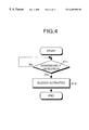
- FIG. 4 is a flow chart for explaining a security operation according to Embodiment 1;
- FIG. 5 is a block diagram showing an example of configuration of a security device according to Embodiment 2;
- FIG. 6 is a flow chart for explaining a security operation according to Embodiment 2.
- FIG. 7 is a block diagram showing an example of configuration of a security device according to Embodiment 3.
- FIG. 8 is a flow chart for explaining a security operation according to Embodiment 3.
- FIG. 9 is a block diagram showing an example of configuration of a security device according to Embodiment 4.
- FIG. 10 is a flow chart for explaining a security operation according to Embodiment 4.
- FIG. 11 is a block diagram showing an example of configuration of a security device according to Embodiment 5.
- FIG. 12 is a flow chart for explaining a security operation according to Embodiment 5.
- FIG. 1 is an exploded view showing an appearance of electronic equipment with a security device according to Embodiment 1 of the present invention mounted thereon.
- the reference numeral 1 indicates a main unit of the equipment.
- the main unit of the equipment 1 has a rectangular construction in which a printed board 3 with an electronic circuit packaged thereon is located between an upper cover 2 and a lower cover 4 .
- the printed board 3 is accommodated in a case formed by the upper cover 2 and the lower cover 4 .
- Each of the upper cover 2 , printed board 3 , and the lower cover 4 has screw holes for engagement at four corners thereon respectively.
- the printed board 3 has screw holes for engagement 31 , 32 , 33 , and 34 at four corners thereon.
- the printed board 3 is screwed down to the casing with screws 51 , 52 , 53 , and 54 , corresponding to the screw holes 31 , 32 , 33 , and 34 respectively, and fixed inside the casing.
- the lower cover includes, for example, platings to bring the lower cover into conduction.
- the plating 5 plays a role of a frame ground to the casing.
- FIG. 2 is a block diagram showing one configuration of the security device to be mounted on the printed board 3 .
- the security device constitutes a part of a circuit packaged on the printed board 3 , and comprises, as shown in FIG. 2, a disassembly detector 101 , an oscillator 102 , a AND circuit 103 and a buzzer 104 .
- This disassembly detector 101 electrically detects the fact that the main unit 1 of the device, namely the casing, is disassembled and outputs a disassembly detection signal (a state of “H” (HIGH))
- the oscillator 102 generates pulses to make the buzzer 104 alert.
- the AND circuit 103 supplies the pulses from the oscillator 102 to the buzzer 104 when the disassembly detection signal outputted from the disassembly detector 101 is “H”.
- the buzzer 104 outputs a sound according to the pulses outputted from the AND circuit 103 .
- FIG. 3 is a circuit diagram showing a simplified configuration of the disassembly detector 101 .
- the disassembly detector 101 is mounted on the printed board 3 matching, for example, a position of the screw hole 31 .
- the disassembly detector 101 comprises, as shown in FIG. 3, a terminal 1001 provided in the screw hole 31 , a resistor 1002 for pull-up, and an amplifier 1003 for amplifying a detection signal against disassembly.
- the screw hole 31 and a screw hole of the lower cover 4 are coupled to each other.
- a terminal 1004 is provided in the screw hole of the lower cover 4 , and the terminals 1001 and 1004 are electrically connected to each other. Connection between the terminals 1001 and 1004 and separation from each other can be realized by giving electric signals “L” (Low) and “H” to the terminals through the resistor 1002 for pull-up.
- FIG. 4 is a flow chart for explaining a security operation according to Embodiment 1. It should be noted that this flow chart explains operations of the entire security device shown in FIG. 2 .
- the printed board 3 and the lower cover 4 are released from the fixed state.
- the contact between the terminal 1001 and the terminal 1004 is cut off.
- step S 11 When an electrical contact between the terminal 1001 and terminal 1004 is maintained, “L” signal is outputted through the connection between terminal 1001 and 1004 having frame ground level, however, when the contact is cut off, the disassembly detection signal changes to “H” because of the pull-up resistor. Namely, the change in the disassembly detection signal to “H” indicates that disassembly of the casing is detected (step S 11 ), so that a pulse signal from the oscillator 102 is supplied to the buzzer 104 , and the buzzer 104 is activated (step S 12 ).
- Embodiment 1 it is electrically detected whether a screw on the main unit 1 of the device is taken out of the unit not.
- the buzzer is activated when the screw is taken off, so that surrounding people can be alerted of illegal acts such as theft, with a simple configuration. With this feature, security against theft of information can be insured.
- At least a part of the casing comprises a frame ground of which a contact position works as a terminal, and a contact position on at least a part of the printed board 3 comprises a terminal, so that it is possible to latch electric connection therebetween with a simple construction.
- the contact positions are connected with a pull-up resistor, so that an act of disassembling the casing can easily be detected with electric changes between HIGH and LOW.
- buzzer 104 is not limited to only the security device, but may be used to perform other functions.
- a disassembly detector 101 may be provided for each of a plurality of screw holes, and in this case, the security function can be enhanced.
- Embodiment 2 Although description was made above for the technique of realizing the security function of alerting surrounding people with a sound to prevent disassembling the casing in Embodiment 1, the present invention is not limited to this Configuration.
- the security function against theft of information may be insured against the acts of disassembling the casing by rewriting information inside the device, such as deletion thereof.
- FIG. 5 is a block diagram showing an example of a configuration of a security device according to Embodiment 2 of the present invention.
- this security device comprises an information processing section 105 and is mounted on the printed board 3 .
- the information processing section 105 comprises, as shown in FIG. 5, a CPU 1051 for controlling the entire equipment according to a program which is not shown in the figure, a system controller 1052 for controlling a memory, a memory 1053 for writing and reading data therein and therefrom under controls by the system controller 1052 , and a hard disk drive (HDD) 1054 for writing and reading data in and from a hard disk not shown under control by the system controller 1052 .
- a hard disk drive (HDD) 1054 for writing and reading data in and from a hard disk not shown under control by the system controller 1052 .
- the disassembly detection signal “H” outputted from the disassembly detector 101 is inputted in the CPU 1051 as an interrupt signal.
- FIG. 6 is a flow chart for explaining the security operations according to Embodiment 2. It should be noted that this flow chart includes controls by the CPU 1051 and explains operations of the entire security device shown in FIG. 5 .
- an interrupt signal is outputted from the disassembly detector 101 to the CPU 1051 (step S 22 ).
- Data is read out from the hard disk in response to occurrence of this interruption (step S 23 ), and the data is rewritten (step S 24 ). Then, the rewritten data is written in the original position again (step S 25 ). It should be noted that the processing of rewriting in step S 24 includes deletion of the data or rewriting a meaningless information on the original data or the like.
- Embodiment 2 the contents stored in a storage medium such as a hard disk are rewritten, for example, when it is detected that a screw of the main unit 1 of the device is taken out of the unit, so that, even if data is stolen, the stolen data would be meaningless, thus preventing theft of the data.
- a storage medium such as a hard disk
- Embodiment 3 also utilizes up a personal computer, as an example of the electronic equipment, in the following description.
- a description will be made for a configuration of Embodiment 3.
- FIG. 7 is a block diagram showing an example of a configuration of a security device according to Embodiment 3 of the present invention.
- this security device comprises a latching circuit 106 , a power-on switch 107 , a AND circuit 108 and a power circuit 109 , and is mounted on the printed board 3 .
- the latching circuit 106 is connected to an output of the disassembly detector 101 , and latches, when a disassembly detection signal “H” is outputted from the disassembly detector 101 , the disassembly detection signal “H”.
- the power-on switch 107 is a hard switch for turning the power ON.
- the AND circuit 108 is connected to an output of the latching circuit 106 and an output of the power-on switch 107 , and when output from the latching circuit 106 is not “H”, namely when the equipment is not being illegally disassembled, passes an ON/OFF signal outputted from the power-on switch 107 to the power circuit 109 .
- the power circuit 109 is connected to the output of the AND circuit 108 and supplies power to the information processing section 105 when a power-ON signal is received.
- FIG. 8 is a flow chart for explaining a security operation according to Embodiment 3. It should be noted that this flow chart explains the operation of the entire security device shown in FIG. 7 .
- a disassembly detection signal is latched by the latching circuit 106 (step S 32 ). With this operation, the signal “H” is supplied to the AND circuit 108 .
- step S 33 a reset state of the CPU 1051 is latched. Therefore, even if the power-on switch 107 is turned ON, since a power-OFF signal is supplied to the power circuit 109 , power can not be supplied from the power circuit 109 to the information processing section 105 , and a restart of the CPU 1051 is inhibited (step S 34 ).
- Embodiment 3 even if a case is reassembled after an illegal disassembly, a power ON/OFF signal gated off with a latched signal inhibits the power to the information processing section 105 from being turned ON again.
- Embodiment 3 a function for security of a restart of the CPU after detection of disassembly of the casing is invalidated may be realized like in Embodiment 4 described below.
- Embodiment 4 also utilizes a personal computer as electronic equipment as an example, in the following description.
- FIG. 9 is a block diagram showing an example a configuration of a security device according to Embodiment 4 of the present invention.
- this security device comprises a power-on•resetting circuit 110 and an AND circuit 111 , and is mounted on the printed board 3 .
- the power-on•resetting circuit 110 is a hard switch for turning the power ON/OFF from the power circuit 109 .
- the AND circuit 111 is connected to an output of the latching circuit 106 and an output of the power-on•resetting circuit 110 , and when output from the latching circuit 106 is not “H”, namely when the equipment is not illegally disassembled, a CPU set/reset signal is outputted from the power-on•resetting circuit 110 to the CPU 1051 .
- FIG. 10 is a flow chart for explaining a security operation according to Embodiment 4. It should be noted that this flowchart explains the operation of the entire security device shown in FIG. 9 .
- a disassembly detection signal is latched by the latching circuit 106 (step S 42 ). With this operation, the signal “H” is supplied to the AND circuit 111 .
- a CPU reset signal is sent to the CPU 1051 , a reset state of the CPU 1051 is latched.
- a power-ON signal is gated regardless of changes in output from the power-on•resetting circuit 110 , so that the output from the AND circuit 111 is a CPU reset signal (step S 43 ).
- step S 44 When the power-on resetting circuit 110 is turned ON, in where release of the reset signal can not be executed to the CPU 1051 as described above (step S 44 ), and if the power has been turned ON (Affirmative in step S 45 ), the CPU reset state is latched. On the other hand, if the power is to be turned ON anew (Negative in step S 45 ), the power is turned ON (step S 46 ), a CPU reset signal is supplied from the AND circuit 111 to the CPU 1051 , and the reset state of the CPU 1051 is effected.
- Embodiments 1 to 4 Although the function for the aforementioned security is programmed to be performed at the point of time when illegal disassembly to equipment is detected in Embodiments 1 to 4, the present invention is not limited to that function, and an act of disassembly such as illegal adaptations may be detected when the case is disassembled due to its repair through an authorized sequence like in Embodiment 5 described below.
- Embodiment 5 also utilizes a personal computer as electronic equipment, as an example in the following description.
- a description will be made for a configuration of Embodiment 5.
- FIG. 11 is a block diagram showing an example of configuration of a security device according to Embodiment 5 of the present invention.
- this security device comprises a counter 112 and an information processing section 113 , and is mounted on the printed board 3 .
- the counter 112 is connected to an output of the disassembly detector 101 as well as to the information processing section 113 , counts a value each time when a disassembly detection signal is outputted from the disassembly detector 101 , and latches the number of times.
- the information processing section 113 comprises, as shown in FIG.
- a CPU 1131 for controlling the entire equipment according to a program which is not shown in the figure, a system controller 1132 for controlling a memory, a memory 1133 for writing and reading data therein and therefrom under controls by the system controller 1132 , a HDD 1134 for writing and reading data in and from a hard disk not shown under controls by the system controller 1132 , a keyboard 1135 used for inputting data such as a password, and a display 1136 for displaying thereon inputted data or the like.
- the memory 1133 stores therein a counter by the counter 112 under controls by the CPU 1131 .
- FIG. 12 is a flow chart for explaining a security operation according to Embodiment 5. It should be noted that this flow includes controls by the CPU 1131 and explains about the operation of the entire security device shown in FIG. 11 .
- the disassembly detection signal is sent to the counter 112 .
- the counter 112 counts a number of occurrences of the disassembly detection signal, and latches the counted values as a number of disassembled times (step S 52 ).
- the CPU 1131 includes the features of processing a password from the keyboard 1135 (step S 53 ), and when a prespecified password for ordinary repair or some other certain reasons is inputted, it is determined that the disassembly is authorized one, and a number of disassembled times stored in the counter 112 is read out and written in the memory 1133 , and is displayed on the display (step S 54 ).
- This number of disassembled times is a history including unauthorized disassembly as well as authorized disassembly, and for this reason, it can be determined whether there have been any illegal adaptations on the casing in the past by subtracting the authorized number of disassembled times from the total number by an authorized repairer. It should be noted that a third person has no chance to know the number of disassembled times latched in the counter 112 unless an appropriate password is inputted.
- Embodiment 5 a number of disassembled times is counted each time when the casing is disassembled and the number of disassembled times is read out when authorized repair is carried out, so that history of illegal adaptations on the casing can easily be checked.
- the history thereof can be latched, so that it is possible to determine whether there have been any adaptations on the casing for an illegal purpose or the like or not.
- Embodiments 1 to 5 Embodiments may be combined according to the desired purposes.
- a contact position of a printed board and that of a case are electrically connected, and a state in which the contact positions are separated is electrically detected, so that the moment at which the electronic equipment is disassembled can be detected, and with this feature, it is possible to obtain a security device which can ensure security for electronic equipment with simple configuration.
- At least a portion of a case comprises a frame ground with its contact area as a terminal, and a contact position on at least a part of a printed board comprises a terminal, so that it is possible to obtain a security device which can latch an electrically connected state between the areas with simple configuration.
- contact positions are connected with a pull-up resistor, so that it is possible to obtain a security device which can easily detect an act of disassembling a case with electric changes of HIGH and LOW.
- a state in which separation between contact positions has been detected is latched, and power supply to electronic equipment is shut down while the state is maintained, so that, when it is found that the equipment has been disassembled once for the purpose of illegal adaptations on the equipment or its unauthorized use, the use of the equipment is forcefully inhibited thereafter, and with this feature, unauthorized use of the equipment due to reassembly after its being shipped can be prevented before its use, and for this reason, it is possible to obtain a security device which can ensure security against theft of information with simple configuration.
- a state in which separation between contact positions has been detected is latched, and an operation of electronic equipment is reset while the state is maintained, so that, when it is found that the equipment has been disassembled once for the purpose of illegal adaptations on the equipment or its unauthorized use, the use of the equipment is forcefully inhibited thereafter regardless of power supply being effected or not, and with this feature, unauthorized use of the equipment due to reassembly after its being shipped can be prevented before its use, and for this reason, it is possible to obtain a security device which can ensure security against theft of information with simple configuration.
- a value is counted each time when separation between contact positions is detected, and the counted values are read out after authentication, so that, when it is found that the equipment has been disassembled once for the purpose of illegal adaptations on the equipment or its unauthorized use, the history thereof is maintained, and with this feature, determination can be made as to whether there has been any change in the equipment for an illegal purpose or the like or not, and for this reason, it is possible to obtain a security device which can ensure security against theft of information with simple configuration.
Abstract
Description
Claims (3)
Applications Claiming Priority (2)
| Application Number | Priority Date | Filing Date | Title |
|---|---|---|---|
| JP16896498A JP3511467B2 (en) | 1998-06-16 | 1998-06-16 | Security equipment |
| JP10-168964 | 1998-06-16 |
Publications (1)
| Publication Number | Publication Date |
|---|---|
| US6489890B1 true US6489890B1 (en) | 2002-12-03 |
Family
ID=15877840
Family Applications (1)
| Application Number | Title | Priority Date | Filing Date |
|---|---|---|---|
| US09/177,827 Expired - Fee Related US6489890B1 (en) | 1998-06-16 | 1998-10-23 | Security device |
Country Status (2)
| Country | Link |
|---|---|
| US (1) | US6489890B1 (en) |
| JP (1) | JP3511467B2 (en) |
Cited By (7)
| Publication number | Priority date | Publication date | Assignee | Title |
|---|---|---|---|---|
| US20020047904A1 (en) * | 2000-08-01 | 2002-04-25 | Hideo Okada | Reusable digital camera that prevents unauthorized use |
| US20050268184A1 (en) * | 2004-04-13 | 2005-12-01 | Yung-Hui Hou | Method and apparatus for monitoring the power state of computer system |
| US20060208884A1 (en) * | 2005-03-09 | 2006-09-21 | Intel Corporation | Device, system and method of detection of input unit disconnection |
| US20070018956A1 (en) * | 2005-07-25 | 2007-01-25 | Samsung Electronics Co., Ltd. | Portable computer and method of controlling the same |
| US20080106366A1 (en) * | 2006-10-31 | 2008-05-08 | Wan-Li Zhang | Damage detection for an anti-theft interface |
| KR100854110B1 (en) | 2008-04-01 | 2008-08-26 | 홍운에이브이 주식회사 | Apparatus of detecting missing on electronic device for electronic-teaching desk and method thereof |
| US20220121750A1 (en) * | 2020-10-15 | 2022-04-21 | Electronics And Telecommunications Research Institute | Method for secure booting using route switchover function for boot memory bus and apparatus using the same |
Families Citing this family (5)
| Publication number | Priority date | Publication date | Assignee | Title |
|---|---|---|---|---|
| JP4574895B2 (en) * | 2001-05-14 | 2010-11-04 | 株式会社日立国際電気 | Wireless terminal |
| EP2442283A1 (en) * | 2009-01-07 | 2012-04-18 | MeadWestvaco Corporation | Security packaging |
| US8278948B2 (en) * | 2009-08-10 | 2012-10-02 | Apple Inc. | Mechanisms for detecting tampering of an electronic device |
| WO2012147170A1 (en) * | 2011-04-26 | 2012-11-01 | 富士通株式会社 | Remote startup device, method and program |
| JP7314852B2 (en) | 2020-03-30 | 2023-07-26 | ブラザー工業株式会社 | Machine tool and judgment method |
Citations (11)
| Publication number | Priority date | Publication date | Assignee | Title |
|---|---|---|---|---|
| US4150371A (en) * | 1978-03-09 | 1979-04-17 | Ripley Company, Inc. | Tamper indicator |
| US4342068A (en) * | 1980-11-10 | 1982-07-27 | Teknational Industries Inc. | Mounting assembly for semiconductor devices and particularly power transistors |
| JPS5917623A (en) * | 1982-07-21 | 1984-01-28 | Matsushita Electric Ind Co Ltd | Device for detecting mounting state of printed board |
| JPS6476347A (en) | 1987-09-18 | 1989-03-22 | Matsushita Electric Ind Co Ltd | Portable terminal |
| JPH0612589A (en) | 1992-06-25 | 1994-01-21 | Nippondenso Co Ltd | Security device |
| US5304987A (en) * | 1992-04-16 | 1994-04-19 | At&T Bell Laboratories | Board removal detection circuit |
| US5353015A (en) * | 1992-04-23 | 1994-10-04 | The United States Of America As Represented By The Secretary Of The Air Force | Tamper detector |
| US5675321A (en) * | 1995-11-29 | 1997-10-07 | Mcbride; Randall C. | Personal computer security system |
| US5818345A (en) * | 1994-12-03 | 1998-10-06 | Icl Systems Ab | Theft protection for electrically-powered articles |
| US5936526A (en) * | 1998-01-13 | 1999-08-10 | Micron Electronics, Inc. | Apparatus for generating an alarm in a portable computer system |
| US5945915A (en) * | 1997-11-06 | 1999-08-31 | International Business Machines Corporation | Computer system for sending an alert signal over a network when a cover of said system has been opened |
-
1998
- 1998-06-16 JP JP16896498A patent/JP3511467B2/en not_active Expired - Fee Related
- 1998-10-23 US US09/177,827 patent/US6489890B1/en not_active Expired - Fee Related
Patent Citations (11)
| Publication number | Priority date | Publication date | Assignee | Title |
|---|---|---|---|---|
| US4150371A (en) * | 1978-03-09 | 1979-04-17 | Ripley Company, Inc. | Tamper indicator |
| US4342068A (en) * | 1980-11-10 | 1982-07-27 | Teknational Industries Inc. | Mounting assembly for semiconductor devices and particularly power transistors |
| JPS5917623A (en) * | 1982-07-21 | 1984-01-28 | Matsushita Electric Ind Co Ltd | Device for detecting mounting state of printed board |
| JPS6476347A (en) | 1987-09-18 | 1989-03-22 | Matsushita Electric Ind Co Ltd | Portable terminal |
| US5304987A (en) * | 1992-04-16 | 1994-04-19 | At&T Bell Laboratories | Board removal detection circuit |
| US5353015A (en) * | 1992-04-23 | 1994-10-04 | The United States Of America As Represented By The Secretary Of The Air Force | Tamper detector |
| JPH0612589A (en) | 1992-06-25 | 1994-01-21 | Nippondenso Co Ltd | Security device |
| US5818345A (en) * | 1994-12-03 | 1998-10-06 | Icl Systems Ab | Theft protection for electrically-powered articles |
| US5675321A (en) * | 1995-11-29 | 1997-10-07 | Mcbride; Randall C. | Personal computer security system |
| US5945915A (en) * | 1997-11-06 | 1999-08-31 | International Business Machines Corporation | Computer system for sending an alert signal over a network when a cover of said system has been opened |
| US5936526A (en) * | 1998-01-13 | 1999-08-10 | Micron Electronics, Inc. | Apparatus for generating an alarm in a portable computer system |
Cited By (13)
| Publication number | Priority date | Publication date | Assignee | Title |
|---|---|---|---|---|
| US6992701B2 (en) * | 2000-08-01 | 2006-01-31 | Sharp Kabushiki Kaisha | Reusable digital camera that prevents unauthorized use |
| US20020047904A1 (en) * | 2000-08-01 | 2002-04-25 | Hideo Okada | Reusable digital camera that prevents unauthorized use |
| US7613934B2 (en) * | 2004-04-13 | 2009-11-03 | Acer Incorporated | Method and apparatus for monitoring the power state of computer system |
| US20050268184A1 (en) * | 2004-04-13 | 2005-12-01 | Yung-Hui Hou | Method and apparatus for monitoring the power state of computer system |
| US20060208884A1 (en) * | 2005-03-09 | 2006-09-21 | Intel Corporation | Device, system and method of detection of input unit disconnection |
| US7321314B2 (en) * | 2005-03-09 | 2008-01-22 | Intel Corporation | Device, system and method of detection of input unit disconnection |
| US7570160B2 (en) * | 2005-07-25 | 2009-08-04 | Samsung Electronics Co., Ltd. | Portable computer and method of controlling the same |
| US20070018956A1 (en) * | 2005-07-25 | 2007-01-25 | Samsung Electronics Co., Ltd. | Portable computer and method of controlling the same |
| US20080106366A1 (en) * | 2006-10-31 | 2008-05-08 | Wan-Li Zhang | Damage detection for an anti-theft interface |
| US9152826B2 (en) * | 2006-10-31 | 2015-10-06 | Hewlett-Packard Development Company, L.P. | Damage detection for an anti-theft interface |
| KR100854110B1 (en) | 2008-04-01 | 2008-08-26 | 홍운에이브이 주식회사 | Apparatus of detecting missing on electronic device for electronic-teaching desk and method thereof |
| US20220121750A1 (en) * | 2020-10-15 | 2022-04-21 | Electronics And Telecommunications Research Institute | Method for secure booting using route switchover function for boot memory bus and apparatus using the same |
| US11556651B2 (en) * | 2020-10-15 | 2023-01-17 | Electronics And Telecommunications Research Institute | Method for secure booting using route switchover function for boot memory bus and apparatus using the same |
Also Published As
| Publication number | Publication date |
|---|---|
| JP2000011268A (en) | 2000-01-14 |
| JP3511467B2 (en) | 2004-03-29 |
Similar Documents
| Publication | Publication Date | Title |
|---|---|---|
| EP0892334B1 (en) | Cabinet security state detection | |
| US5760690A (en) | Portable computer with integrated alarm system | |
| US5945915A (en) | Computer system for sending an alert signal over a network when a cover of said system has been opened | |
| US6026492A (en) | Computer system and method to disable same when network cable is removed | |
| US6489890B1 (en) | Security device | |
| US4908608A (en) | Alarmcard | |
| US5675321A (en) | Personal computer security system | |
| US5317304A (en) | Programmable microprocessor based motion-sensitive alarm | |
| US6002427A (en) | Security system with proximity sensing for an electronic device | |
| US7100210B2 (en) | Hood intrusion and loss of AC power detection with automatic time stamp | |
| US5970227A (en) | Wireless proximity detector security feature | |
| US5027397A (en) | Data protection by detection of intrusion into electronic assemblies | |
| KR101140477B1 (en) | Consumer abuse detection system and method | |
| US6286102B1 (en) | Selective wireless disablement for computers passing through a security checkpoint | |
| US5712973A (en) | Wireless proximity containment security | |
| WO2001063994A2 (en) | Tamper proof case for electronic devices having memories with sensitive information | |
| US5872515A (en) | Laptop computer with an anti-theft alarm function and a method of controlling the same | |
| US20050088303A1 (en) | Tamper sensing method and apparatus | |
| US6191503B1 (en) | Computer with a chassis intrusion detector | |
| US20100070791A1 (en) | Power supply monitoring method and system | |
| JP2006229667A (en) | Tamper-resistant device, and tamper-resistant method | |
| CA2317889A1 (en) | Anti-theft device for computers | |
| US6388574B1 (en) | Optical chassis intrusion detection with power on or off | |
| US5826009A (en) | Protection of software from physical and electronic interrogation by sealing and checking password | |
| JP2857998B2 (en) | Gaming machine call display device |
Legal Events
| Date | Code | Title | Description |
|---|---|---|---|
| AS | Assignment |
Owner name: FUJITSU LIMITED, JAPAN Free format text: ASSIGNMENT OF ASSIGNORS INTEREST;ASSIGNOR:INOUE, NAOYUKI;REEL/FRAME:009550/0514 Effective date: 19981020 |
|
| FEPP | Fee payment procedure |
Free format text: PAYOR NUMBER ASSIGNED (ORIGINAL EVENT CODE: ASPN); ENTITY STATUS OF PATENT OWNER: LARGE ENTITY Free format text: PAYER NUMBER DE-ASSIGNED (ORIGINAL EVENT CODE: RMPN); ENTITY STATUS OF PATENT OWNER: LARGE ENTITY |
|
| FPAY | Fee payment |
Year of fee payment: 4 |
|
| AS | Assignment |
Owner name: BOC EDWARDS, INC., MASSACHUSETTS Free format text: ASSIGNMENT OF ASSIGNORS INTEREST;ASSIGNOR:THE BOC GROUP, INC.;REEL/FRAME:019767/0251 Effective date: 20070330 Owner name: BOC EDWARDS, INC.,MASSACHUSETTS Free format text: ASSIGNMENT OF ASSIGNORS INTEREST;ASSIGNOR:THE BOC GROUP, INC.;REEL/FRAME:019767/0251 Effective date: 20070330 |
|
| REMI | Maintenance fee reminder mailed | ||
| LAPS | Lapse for failure to pay maintenance fees | ||
| STCH | Information on status: patent discontinuation |
Free format text: PATENT EXPIRED DUE TO NONPAYMENT OF MAINTENANCE FEES UNDER 37 CFR 1.362 |
|
| FP | Lapsed due to failure to pay maintenance fee |
Effective date: 20101203 |