US6491626B1 - Articulation systems for positioning minimally invasive surgical tools - Google Patents
Articulation systems for positioning minimally invasive surgical tools Download PDFInfo
- Publication number
- US6491626B1 US6491626B1 US09/548,901 US54890100A US6491626B1 US 6491626 B1 US6491626 B1 US 6491626B1 US 54890100 A US54890100 A US 54890100A US 6491626 B1 US6491626 B1 US 6491626B1
- Authority
- US
- United States
- Prior art keywords
- articulator
- longitudinally extending
- control wire
- extending body
- transverse grooves
- Prior art date
- Legal status (The legal status is an assumption and is not a legal conclusion. Google has not performed a legal analysis and makes no representation as to the accuracy of the status listed.)
- Expired - Fee Related
Links
Images


Classifications
-
- A—HUMAN NECESSITIES
- A61—MEDICAL OR VETERINARY SCIENCE; HYGIENE
- A61B—DIAGNOSIS; SURGERY; IDENTIFICATION
- A61B17/00—Surgical instruments, devices or methods, e.g. tourniquets
- A61B17/28—Surgical forceps
- A61B17/29—Forceps for use in minimally invasive surgery
-
- A—HUMAN NECESSITIES
- A61—MEDICAL OR VETERINARY SCIENCE; HYGIENE
- A61B—DIAGNOSIS; SURGERY; IDENTIFICATION
- A61B1/00—Instruments for performing medical examinations of the interior of cavities or tubes of the body by visual or photographical inspection, e.g. endoscopes; Illuminating arrangements therefor
-
- A—HUMAN NECESSITIES
- A61—MEDICAL OR VETERINARY SCIENCE; HYGIENE
- A61B—DIAGNOSIS; SURGERY; IDENTIFICATION
- A61B17/00—Surgical instruments, devices or methods, e.g. tourniquets
- A61B17/28—Surgical forceps
-
- F—MECHANICAL ENGINEERING; LIGHTING; HEATING; WEAPONS; BLASTING
- F16—ENGINEERING ELEMENTS AND UNITS; GENERAL MEASURES FOR PRODUCING AND MAINTAINING EFFECTIVE FUNCTIONING OF MACHINES OR INSTALLATIONS; THERMAL INSULATION IN GENERAL
- F16D—COUPLINGS FOR TRANSMITTING ROTATION; CLUTCHES; BRAKES
- F16D1/00—Couplings for rigidly connecting two coaxial shafts or other movable machine elements
-
- A—HUMAN NECESSITIES
- A61—MEDICAL OR VETERINARY SCIENCE; HYGIENE
- A61B—DIAGNOSIS; SURGERY; IDENTIFICATION
- A61B1/00—Instruments for performing medical examinations of the interior of cavities or tubes of the body by visual or photographical inspection, e.g. endoscopes; Illuminating arrangements therefor
- A61B1/005—Flexible endoscopes
- A61B1/0051—Flexible endoscopes with controlled bending of insertion part
- A61B1/0055—Constructional details of insertion parts, e.g. vertebral elements
-
- A—HUMAN NECESSITIES
- A61—MEDICAL OR VETERINARY SCIENCE; HYGIENE
- A61B—DIAGNOSIS; SURGERY; IDENTIFICATION
- A61B1/00—Instruments for performing medical examinations of the interior of cavities or tubes of the body by visual or photographical inspection, e.g. endoscopes; Illuminating arrangements therefor
- A61B1/005—Flexible endoscopes
- A61B1/0051—Flexible endoscopes with controlled bending of insertion part
- A61B1/0057—Constructional details of force transmission elements, e.g. control wires
-
- A—HUMAN NECESSITIES
- A61—MEDICAL OR VETERINARY SCIENCE; HYGIENE
- A61B—DIAGNOSIS; SURGERY; IDENTIFICATION
- A61B17/00—Surgical instruments, devices or methods, e.g. tourniquets
- A61B17/00234—Surgical instruments, devices or methods, e.g. tourniquets for minimally invasive surgery
- A61B2017/00292—Surgical instruments, devices or methods, e.g. tourniquets for minimally invasive surgery mounted on or guided by flexible, e.g. catheter-like, means
- A61B2017/003—Steerable
- A61B2017/00305—Constructional details of the flexible means
- A61B2017/00309—Cut-outs or slits
-
- A—HUMAN NECESSITIES
- A61—MEDICAL OR VETERINARY SCIENCE; HYGIENE
- A61B—DIAGNOSIS; SURGERY; IDENTIFICATION
- A61B17/00—Surgical instruments, devices or methods, e.g. tourniquets
- A61B17/28—Surgical forceps
- A61B17/29—Forceps for use in minimally invasive surgery
- A61B2017/2926—Details of heads or jaws
- A61B2017/2927—Details of heads or jaws the angular position of the head being adjustable with respect to the shaft
-
- Y—GENERAL TAGGING OF NEW TECHNOLOGICAL DEVELOPMENTS; GENERAL TAGGING OF CROSS-SECTIONAL TECHNOLOGIES SPANNING OVER SEVERAL SECTIONS OF THE IPC; TECHNICAL SUBJECTS COVERED BY FORMER USPC CROSS-REFERENCE ART COLLECTIONS [XRACs] AND DIGESTS
- Y10—TECHNICAL SUBJECTS COVERED BY FORMER USPC
- Y10T—TECHNICAL SUBJECTS COVERED BY FORMER US CLASSIFICATION
- Y10T403/00—Joints and connections
- Y10T403/54—Flexible member is joint component
Definitions
- the present invention relates to surgical articulators.
- an articulating segment mounted between the distal end of a positioning rod and the base of the tool.
- articulators are typically steered (ie: deflected) to position the therapeutic tool adjacent to the desired tissue by means of control rods, cables or other actuation mechanisms located in a hand piece at a proximal end of the positioning rod.
- Traditional means for providing articulation include devices comprising a multiplicity of annular rings which are interlinked together to form pivots which allow for flexure of the articulator assembly. Specifically, these pivots are oriented in a manner which creates one or more preferential bending planes.
- This type of articulator design is that it can lack sufficient positional stability for precision tissue manipulation when mounted to the distal end of a positioning rod.
- modes of instability of such devices include torsional instability about its longitudinal axis (especially when deflected, as the moment arm increases with increased articulation), radial instability about the longitudinal axis, (including lateral instability in directions perpendicular to the preferred bending plane of the articulator), and axial instability along the longitudinal axis of the articulator body.
- annular ring designs are typically machined from separate stainless steel pieces which must be assembled to form the articulator assembly, with high material and labor costs.
- a first control wire is used to control the articulation of the device, (such as for deflecting the angle of a scraper or a pair of forceps from the longitudinal axis of the positioning rod), and a second control wire is used to control the operation of the device, (such as for opening and closing the jaws of a pair of forceps).
- a common problem of such existing systems is “crosstalk” in which attempts to control the degree of articulation by displacing the device's articulation control wire results in displacement of the tool control wire, which results in tool operation, or vice versa. Consequently, when operating forceps for example, the forceps jaws will tend either to open or to close as the angle of articulation is varied. Conversely, when attempting to open or close the forceps jaws, the angle of articulation of the forceps will tend to change.
- This “crosstalk” problem is undesirable since the surgeon may simply desire to open and close the forceps (thus grasping targeted tissue) while the forceps remain in a constant deflected position. Similarly, the surgeon may simply wish to articulate the angle of the forceps without either opening or closing their jaws, (such as when first approaching the target tissue).
- articulators are typically constructed from soft plastics such as low durometer polyeurathanes in order to have sufficient bending flexibility.
- soft plastics such as low durometer polyeurathanes
- the use of such soft plastics results in significant losses to the device's positional stability.
- the articulator tends to compress in the axial direction when the articulation control wire is tensioned to deflect the distal end of the articulator.
- Such unwanted axial compression results in positioning inaccuracies which further exacerbates crosstalk problems.
- the present invention provides an articulation system for positioning various surgical tools during surgical procedures, and is especially useful in positioning surgical tools in minimally invasive surgical procedures.
- the present invention provides a controllable articulator which is preferably mounted between the distal end of a positioning rod and the base of the surgical tool.
- a controllable articulator which is preferably mounted between the distal end of a positioning rod and the base of the surgical tool.
- the present articulator system comprises a longitudinally extending body which may preferably be integrally formed from a single piece or block of material.
- the present articulator may preferably be formed by injection molding or formed by Steriolithography (SLA).
- SLA Steriolithography
- the present articulator is fabricated from a relatively rigid and strong thermoplastic material, for example acetal.
- a relatively rigid and strong thermoplastic material for example acetal.
- the novel shape and characteristics of the present articulator system allows it to exhibit excellent bending flexibility in a preferred bending plane, yet still be constructed of a sufficiently hard material to prevent axial compression, radial deflection in planes other than the preferred bending plane (including lateral deflection in a plane perpendicular to the preferred bending plane) and torsional deflection about the central axis of the articulator body.
- the positioning of the present articulator can be very precisely controlled through various degrees of deflection.
- novel shape of the present articulator also offers many advantages in its fabrication. For example, when injection molding the present invention, a tool control wire lumen and an articulation control wire lumen can be formed without “core pins” being required in mold shut-offs as is typically necessary to carve out separate actuator wire and control wire lumens as a hot plastic is initially flowed through the mold.
- an advantage of not requiring such “core pins” when injection molding the present articulator is that the present articulator can be fabricated to very small dimensions.
- the size of the lumens are typically limited to the minimum diameter and length of a core pin which can be passed through the mold. This is due to the fact that it is not possible to use a core pin which is too thin since its structure will be affected by the hot plastic surrounding it during the molding process.
- the present articulator can be formed within interlocking 2-piece mold shut-offs without requiring the insertion of core pins into the mold to carve out lumens for either of the articulation or tool(i.e.: actuation) control wires.
- the present articulator preferably comprises a longitudinally extending body, having a plurality of transverse grooves extending inwardly from opposite lateral sides of the longitudinally extending body.
- the transverse grooves preferably extend inwardly from each of the opposite lateral sides of the device in an alternating manner along the length of the longitudinally extending body.
- the transverse grooves extend farther into the articulator body from one side of the articulator than from the other.
- the longer grooves will be disposed on an inner bending surface of the articulator and will be compressed together as the articulator deflects in a preferred bending plane and the shorter grooves will be disposed on an outer bending surface of the articulator and will spread apart to offer stress relief as the articulator is deflected.
- the depth and spacing of the transverse grooves will define a neutral bending axis through the articulator body.
- the articulator body preferably further comprises a plurality of recesses extending inwardly from the opposite sides in an alternating manner along the length of the longitudinally extending body.
- a plurality of recesses projecting inwardly from the opposite sides of the articulator body together preferably define both an articulation control wire lumen and a tool control wire lumen.
- the tool control lumen is disposed collinear with the neutral bending axis of the articulator.
- An important advantage of having the tool control wire, (which is received in the tool control wire lumen), collinear with a neutral bending axis of the articulator is that the potential for crosstalk is eliminated. This is due to the fact that deflection of the articulator about its neutral bending axis will neither cause tension nor compression in the tool control wire.
- the tool control may, for example, be used to open and close teeth on a gripping device unaffected by deflection of the articulator caused by tensioning or compressing the articulation control wire (disposed in the articulation control wire lumen running parallel to the tool control wire).
- the surgeon may use forceps positioned at the distal end of the articulator to grasp tissue when the articulator is in an articulated (i.e.: deflected) position and then apply a load to the articulator by pulling on the tissue.
- the forceps jaw opening control wire along the neutral bending axis of the articulator, the articulator will maintain the deflected position and will not straighten out as the forceps jaw control wire slides through the articulator to open or close the forceps.
- another advantage of the present invention is that by placing the tool control wire collinear with the neutral axis, axial loads on the tool control wire do not cause unintended deflections of the articulator.
- transverse grooves which extend partially across the longitudinally extending body in an alternating fashion offer the advantage of significant bending flexibility in a preferred bending plane.
- the innermost ends of the transverse grooves are rounded to further relieve bending stresses when the articulator is deflected.
- the transverse grooves are spaced evenly apart along the length of the articulator. As such, the articulator bends with a uniform curvature along its length. In other preferred aspects of the invention, the spacing between the transverse grooves is varied such that the articulator bends with different arcs of curvature along its length. For example, the transverse grooves can be spaced closer together at the distal end of the articulator such that maximum deflection curvature occurs at the distal end of the articulator.
- the novel shape of the present articulator makes it highly flexible in a preferred bending plane, yet highly resistant to loads in other directions. Specifically, the present articulator is resistant to lateral loads, (perpendicular to the plane of deflection), torsional loads, and axial loads, or any combination thereof.
- free floating tension/compression sleeves may optionally be placed in the tool and articulation control wire lumens over the tool and articulation control wires thus preventing the actuators from sliding thereby improving control feel by imparting further rigidity to the articulator.
- such sleeves can be made of low coefficient of friction materials thereby reducing excessive actuation friction.
- the plurality of recesses projecting inwardly from the top and bottom of the device together define a large central lumen which is adapted to receive both the articulation control wire and the tool control wire therethrough.
- a large central lumen may optionally have a keyhole shape (in cross section) to assist in holding the tool control wire coincident with the neutral bending axis of the articulator, as will be explained.
- the recesses which extend inwardly from the opposite sides of the articulator body are eliminated.
- the articulation control wire lumen is formed as a series of spaced apart cylinders which pass between the transverse grooves extending from one side of the articulator body.
- the articulation control wire lumen thus formed opens fully into the transverse grooves which extend into one side of the articulator body.
- the tool control wire lumen (which is disposed collinear with the neutral bending axis) opens directly into the innermost ends of the transverse grooves which extend inwardly from both opposite sides of the articulator body.
- FIG. 1 is a perspective view of an articulator according to the present invention.
- FIG. 2A is a sectional view showing one half of the articulator of FIG. 1 .
- FIG. 2B corresponds to FIG. 2A, further showing the tool and articulation control wires.
- FIG. 3 is a side sectional view corresponding to FIG. 2 A.
- FIG. 4 is an end view corresponding to FIG. 3 .
- FIG. 5 is a sectional view taken along line 5 — 5 in FIG. 3 .
- FIG. 6 is a sectional view taken along line 6 — 6 in FIG. 3 .
- FIG. 7 is a sectional view taken along line 7 — 7 in FIG. 3 .
- FIG. 8 is a top plan view of the articulator of FIG. 1 .
- FIG. 9 is a bottom plan view of the articulator of FIG. 1 .
- FIG. 10A is a side elevation view of the articulator of FIG. 1 .
- FIG. 10B is a view corresponding to FIG. 10A, but showing the spacing between adjacent transverse grooves narrowing toward one end of the articulator.
- FIG. 11A is a sectional perspective view of an alternate design of an articulator according to the present invention.
- FIG. 11B is a sectional perspective view of a articulator of FIG. 11A, showing the actuator control wire and the tool control wire received together in a large central lumen.
- FIG. 11C is an end view corresponding to FIG. 11A, showing a single racetrack-shaped central lumen.
- FIG. 11D is an end view corresponding to FIG. 11A, showing a single keyhole-shaped central lumen.
- FIG. 12 is a perspective view of yet another design of an articulator according to the present invention.
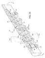
- FIG. 13 is a side elevation view of the articulator of FIG. 12 .
- FIG. 14 is an end view of the articulator of FIG. 12 .
- FIG. 15 is a sectional view taken along line 15 — 15 in FIG. 14 .
- FIG. 16 is a bottom sectional view taken along line 16 — 16 in FIG. 15 .
- FIG. 17 is a sectional side view of the articulator of FIG. 1 in a deflected position.
- the present invention provides an articulation system which is adapted to be mounted between the distal end of a positioning rod and the base of a surgical tool such as a scraper, a curette, forceps, graspers or scissors.
- the present articulator is designed to bend within a preferred bending plane under the influence of tension from an articulation control wire passing therethrough.
- the preferred bending characteristics of the present articulator facilitates the accurate positioning of the various surgical tools which may be mounted on its distal end.
- the present articulation system is particularly well suited for minimally invasive surgical applications in which a cannula is first introduced into the patient's body and the surgical tool (mounted to the articulator which is then mounted to a positioning rod) is then introduced through the cannula.
- the surgical tool and the articulator can be advanced to protrude out of the distal end of the cannula such that the articulator can then be deflected to direct the surgical tool into orientations which are not collinear with a cental axis of either the positioning rod or the cannula.
- an articulator 20 is provided.
- Articulator 20 is preferably monolithically fabricated from a single, integral piece of high density thermoplastic such as acetal.
- the novel shape of articulator 20 permits easy, highly flexible bending in direction R, (due to the presence of transverse grooves 22 A and 22 B which provide stress relief), yet prevents lateral bending in directions L, and also resists axial compression in direction A and torsional bending in direction T.
- FIG. 2 shows one half of the articulator.
- a plurality of transverse grooves 22 A and 22 B extend inwardly into opposite lateral sides (illustrated herein as the top and bottom of articulator 20 ).
- grooves 22 B extend further inwardly (i.e.: laterally across) articulator 20 than grooves 22 A.
- articulator 20 is adapted to flex in direction R as shown in FIG. 17, with grooves 22 B narrowing as the articulator is bent in direction R while grooves 22 A spread apart to provide stress relief as the articulator bends.
- the “preferred bending plane” for articulator 20 is shown as “BP” in FIG. 4 .
- articulator 20 when actuated, articulator 20 is adapted to preferentially bend in direction R in preferred bending plane BP).
- a plurality of recesses 23 A and 23 B extend inwardly from the opposite top and bottom sides of articulator 20 .
- Recesses 23 A and 23 B extend inwardly such that their innermost ends 27 and 29 , overlap, so as to define an actuator control wire lumen 24 and a tool control wire lumen 26 through articulator 20 as shown.
- an actuation control wire 30 is slidably received within actuator control wire lumen 24 and a tool control wire 32 is slidably received within tool control wire lumen 26 .
- recesses 23 A and 23 B extending inwardly with their innermost ends 27 and 27 overlapping as shown (to form lumens 24 and 26 ) is that it is possible to injection mold articulator 20 from a single monolithic piece of thermoplastic or other suitable material.
- recesses 23 A and 23 B can be formed by similar shaped protrusions disposed on opposite halves of the mold shut-offs.
- lumens 24 and 26 are formed to extend through articulator 20 without requiring the insertion of any core pins into an injection mold to first carve out such lumens. Consequently, the present articulator can be fabricated to very small dimensions since a thin core pin is not required.
- articulator control wire 30 When articulator control wire 30 is tensioned, (i.e.: pulled in direction D 1 ), articulator 20 will be deflected in direction R to a position as show in FIG. 17 . (For clarity, portions of wires 30 and 32 are illustrated in phantom in FIG. 17 ).
- tool control wire 32 When tool control wire 32 is tensioned, (i.e.: pulled in direction D 1 ), control wire 32 can actuate a tool.
- control wire 32 can be used to open jaws 72 of forceps 70 .
- tool control wire 32 is preferably disposed along the neutral bending axis 25 (FIG. 10A) of articulator 20 .
- An important advantage of disposing control wire 32 collinear with neutral axis 25 is that control wire 32 will neither be tensioned nor compressed as articulator 20 deflects back and forth in direction R under the control of actuator control wire 30 .
- the angle of articulation (in direction R within the device's preferred bending plane BP) can be easily changed by either tensioning or relaxing tension on articulation control wire 30 without axially displacing tool control wire 32 (which would for example induce “crosstalk” affecting the operation of the surgical tool, such as opening or closing jaws 72 of forceps 70 ).
- control wire 32 collinear with the neutral bending axis of articulator 20 , the operation of a tool (such as forceps 70 ) is fully independent of operation of the controlling of the angle of articulation (in direction R) of articulator 20 .
- FIGS. 4 to 7 Further details of the internal structure of articulator 20 can be seen in FIGS. 4 to 7 .
- articulator 20 As can be seen in FIGS. 8 and 9, the lateral sides of articulator 20 are substantially straight when viewed from either the top or the bottom of the device.
- Such preferred shape of articulator 20 i.e.: wherein grooves 22 a and 22 b project into the top and bottom of the device, with no similar grooves projecting into the lateral sides of the device) offers resistance to bending both in lateral directions L and torsional directions T.
- inner most ends 31 and 33 of grooves 22 A and 22 B respectively are preferably rounded to further relieve bending stresses when articulator 20 is bent in its preferred bending plane, (BP in FIG. 4 ), in direction R, thus enabling a high degree of flexibility in the preferred bending plane.
- FIG. 10B shows an aspect of the invention where the spacing between adjacent grooves 22 B (and 22 A) is decreased from S 1 to S 2 towards distal end 37 of articulator 20 .
- the articulator will tend to exhibit a greater degree of curvature towards its distal end 37 as compared to its proximal end 35 when articulator control wire 30 is tensioned.
- the articulator of FIG. 10B is particularly well suited for accessing highly curved or branching passageways in the patient's body.
- FIGS. 11A to 11 D show an alternate aspect of the present articulator.
- Articulator 40 is shown in cross-sectional view, similar to the view of articulator 20 shown in FIG. 2 A. In contrast to articulator 20 , articulator 40 has a large central lumen 42 passing therethrough. Articulator 40 is similar to articulator 20 with transverse grooves 42 A and 42 B functioning similar to grooves 22 A and 22 B in articulator 20 . Recesses 43 A and 43 B are, however, differently shaped from recesses 23 A and 23 B such that only one large central lumen 42 is formed through articulator 40 .
- Lumen 42 may be a variety of shapes including racetrack-shaped as is shown in FIG. 11C or keyhole-shaped as is shown in FIG. 11 D.
- tension on actuation control wire 50 will cause it to move to the contracting side of articulator 40 , as shown in FIGS. 11C and 11D.
- a tool control wire 52 is also received within central lumen 42 .
- Tool control wire 52 will tend to move to the opposite side of lumen 42 such that tool control wire 52 will remain disposed along the neutral bending axis 45 of articulator 40 as shown.
- An advantage of the keyhole shape of lumen 42 shown in FIG. 11D is that it will tend to further restrict movement of tool control wire 52 such that it remains collinear with neutral bending axis 45 .
- FIG. 12 shows another alternate aspect of the present articulator.
- Articulator 60 has transverse grooves 62 A and 62 B (which operate similar to grooves 22 A and 22 B in articulator 20 ) extending inwardly from the top and bottom of the device as shown.
- An articulation control wire lumen 64 and a tool control wire lumen 66 are provided as shown. Further details of lumens 64 and 66 are seen in FIGS. 15 an 16 .
- articulation control wire lumen 64 passes between and opens into transverse grooves 62 B and control wire lumen 66 passes through the innermost ends of both transverse grooves 62 A and 62 B.
- Tool control wire lumen 66 is preferably disposed such that a tool control wire (not shown) received therein is collinear with the neutral bending axis 65 of articulator 60 . Accordingly, as the articulator is deflected, grooves 62 B will tend to close as grooves 62 A will tend to open. Being disposed on neutral bending axis 65 , a tool control wire passing through lumen 66 will neither tend to be put under tension or compression during articulation.
- articulation control wire lumen 66 such that it opens both into the innermost ends of grooves 62 A and 62 B further reduces the bending resistance of the articulator by reducing its section modulus.
- articulator 60 is highly flexible to bend in direction R in bending plane BP.
- a neutral axis 65 is located at the midway point between the innermost ends of transverse grooves 62 A and 62 B, as shown.
- a plurality of articulators 20 , 40 , or 60 can be attached together end to end.
- the angle of articulation of the device may be substantially increased. For example, articulation for up to 360° is possible.
- a plurality of articulators are be mounted together end to end with successive articulators being rotated 180° about a central longitudinal axis extending therethrough. When deflected, the combined articulator assembly will deflect into an S-shaped curve.
Abstract
Description
Claims (35)
Priority Applications (2)
| Application Number | Priority Date | Filing Date | Title |
|---|---|---|---|
| US09/548,901 US6491626B1 (en) | 1999-04-16 | 2000-04-13 | Articulation systems for positioning minimally invasive surgical tools |
| PCT/US2000/010182 WO2000062687A1 (en) | 1999-04-16 | 2000-04-14 | Articulation systems for positioning minimally invasive surgical tools |
Applications Claiming Priority (2)
| Application Number | Priority Date | Filing Date | Title |
|---|---|---|---|
| US12970399P | 1999-04-16 | 1999-04-16 | |
| US09/548,901 US6491626B1 (en) | 1999-04-16 | 2000-04-13 | Articulation systems for positioning minimally invasive surgical tools |
Publications (1)
| Publication Number | Publication Date |
|---|---|
| US6491626B1 true US6491626B1 (en) | 2002-12-10 |
Family
ID=36258633
Family Applications (1)
| Application Number | Title | Priority Date | Filing Date |
|---|---|---|---|
| US09/548,901 Expired - Fee Related US6491626B1 (en) | 1999-04-16 | 2000-04-13 | Articulation systems for positioning minimally invasive surgical tools |
Country Status (2)
| Country | Link |
|---|---|
| US (1) | US6491626B1 (en) |
| WO (1) | WO2000062687A1 (en) |
Cited By (174)
| Publication number | Priority date | Publication date | Assignee | Title |
|---|---|---|---|---|
| US6645218B1 (en) | 2002-08-05 | 2003-11-11 | Endius Incorporated | Surgical instrument |
| US20040034343A1 (en) * | 2002-08-16 | 2004-02-19 | Gillespie Walter D. | Articulation mechanism |
| US20040181138A1 (en) * | 2003-03-12 | 2004-09-16 | Gerhard Hindricks | Method for treating tissue |
| US20040199051A1 (en) * | 2003-04-03 | 2004-10-07 | Thomas Weisel | Articulating shaft |
| US20040236316A1 (en) * | 2003-05-23 | 2004-11-25 | Danitz David J. | Articulating mechanism for remote manipulation of a surgical or diagnostic tool |
| US20050049051A1 (en) * | 2001-06-28 | 2005-03-03 | Pinard Adam I. | Lead screw coupling |
| US20050107667A1 (en) * | 2003-05-23 | 2005-05-19 | Novare Surgical Systems, Inc. | Hand-actuated device for remote manipulation of a grasping tool |
| US20050273084A1 (en) * | 2004-06-07 | 2005-12-08 | Novare Surgical Systems, Inc. | Link systems and articulation mechanisms for remote manipulation of surgical or diagnostic tools |
| US20060111615A1 (en) * | 2004-11-23 | 2006-05-25 | Novare Surgical Systems, Inc. | Articulating sheath for flexible instruments |
| US20060201130A1 (en) * | 2005-01-31 | 2006-09-14 | Danitz David J | Articulating mechanisms with joint assembly and manual handle for remote manipulation of instruments and tools |
| US20070123986A1 (en) * | 2005-08-16 | 2007-05-31 | Laurent Schaller | Methods of Distracting Tissue Layers of the Human Spine |
| US20080086047A1 (en) * | 2003-03-12 | 2008-04-10 | Biosense Webster, Inc. | Deflectable catheter with hinge |
| US20080121595A1 (en) * | 2006-11-28 | 2008-05-29 | Trulaske Steven L | Shelf Organizer |
| US20080234687A1 (en) * | 2005-08-16 | 2008-09-25 | Laurent Schaller | Devices for treating the spine |
| US20080312506A1 (en) * | 2007-06-14 | 2008-12-18 | Ethicon Endo-Surgery, Inc. | Control mechanism for flexible endoscopic device and method of use |
| US7655004B2 (en) | 2007-02-15 | 2010-02-02 | Ethicon Endo-Surgery, Inc. | Electroporation ablation apparatus, system, and method |
| US7670284B2 (en) | 2004-08-31 | 2010-03-02 | Surgical Solutions Llc | Medical device with articulating shaft |
| US7678117B2 (en) * | 2004-06-07 | 2010-03-16 | Novare Surgical Systems, Inc. | Articulating mechanism with flex-hinged links |
| US7740633B2 (en) | 2003-10-23 | 2010-06-22 | Trans1 Inc. | Guide pin for guiding instrumentation along a soft tissue tract to a point on the spine |
| US20100160735A1 (en) * | 2008-12-18 | 2010-06-24 | Ethicon Endo-Surgery, Inc. | Steerable surgical access devices and methods |
| US20100198005A1 (en) * | 2009-01-30 | 2010-08-05 | Ethicon Endo-Surgery, Inc. | Surgical access device |
| US7815662B2 (en) | 2007-03-08 | 2010-10-19 | Ethicon Endo-Surgery, Inc. | Surgical suture anchors and deployment device |
| US20100280526A1 (en) * | 2009-04-29 | 2010-11-04 | Arch Day Design, Llc | Medical Device With Articulating Shaft Mechanism |
| US20100318067A1 (en) * | 2009-06-11 | 2010-12-16 | St. Jude Medical Puerto Rico Llc | Apparatus and methods for catheter steerability |
| US7862554B2 (en) | 2007-04-16 | 2011-01-04 | Intuitive Surgical Operations, Inc. | Articulating tool with improved tension member system |
| US20110184231A1 (en) * | 2009-07-28 | 2011-07-28 | Page Brett M | Deflectable instrument ports |
| US8012182B2 (en) | 2000-07-25 | 2011-09-06 | Zimmer Spine S.A.S. | Semi-rigid linking piece for stabilizing the spine |
| US8037591B2 (en) | 2009-02-02 | 2011-10-18 | Ethicon Endo-Surgery, Inc. | Surgical scissors |
| US8070759B2 (en) | 2008-05-30 | 2011-12-06 | Ethicon Endo-Surgery, Inc. | Surgical fastening device |
| US8075572B2 (en) | 2007-04-26 | 2011-12-13 | Ethicon Endo-Surgery, Inc. | Surgical suturing apparatus |
| US8100824B2 (en) | 2003-05-23 | 2012-01-24 | Intuitive Surgical Operations, Inc. | Tool with articulation lock |
| US8100922B2 (en) | 2007-04-27 | 2012-01-24 | Ethicon Endo-Surgery, Inc. | Curved needle suturing tool |
| US8114119B2 (en) | 2008-09-09 | 2012-02-14 | Ethicon Endo-Surgery, Inc. | Surgical grasping device |
| US8114072B2 (en) | 2008-05-30 | 2012-02-14 | Ethicon Endo-Surgery, Inc. | Electrical ablation device |
| US8142473B2 (en) | 2008-10-03 | 2012-03-27 | Tyco Healthcare Group Lp | Method of transferring rotational motion in an articulating surgical instrument |
| US8157834B2 (en) | 2008-11-25 | 2012-04-17 | Ethicon Endo-Surgery, Inc. | Rotational coupling device for surgical instrument with flexible actuators |
| US8172772B2 (en) | 2008-12-11 | 2012-05-08 | Ethicon Endo-Surgery, Inc. | Specimen retrieval device |
| US8182417B2 (en) * | 2004-11-24 | 2012-05-22 | Intuitive Surgical Operations, Inc. | Articulating mechanism components and system for easy assembly and disassembly |
| US8211125B2 (en) | 2008-08-15 | 2012-07-03 | Ethicon Endo-Surgery, Inc. | Sterile appliance delivery device for endoscopic procedures |
| US8241204B2 (en) | 2008-08-29 | 2012-08-14 | Ethicon Endo-Surgery, Inc. | Articulating end cap |
| US8262680B2 (en) | 2008-03-10 | 2012-09-11 | Ethicon Endo-Surgery, Inc. | Anastomotic device |
| US8262655B2 (en) | 2007-11-21 | 2012-09-11 | Ethicon Endo-Surgery, Inc. | Bipolar forceps |
| US8262563B2 (en) * | 2008-07-14 | 2012-09-11 | Ethicon Endo-Surgery, Inc. | Endoscopic translumenal articulatable steerable overtube |
| CN101048101B (en) * | 2004-06-07 | 2012-11-14 | 诺瓦尔外科系统公司 | Articulating mechanism with flex-hinged links |
| US8317806B2 (en) | 2008-05-30 | 2012-11-27 | Ethicon Endo-Surgery, Inc. | Endoscopic suturing tension controlling and indication devices |
| US8337394B2 (en) | 2008-10-01 | 2012-12-25 | Ethicon Endo-Surgery, Inc. | Overtube with expandable tip |
| US8353487B2 (en) | 2009-12-17 | 2013-01-15 | Ethicon Endo-Surgery, Inc. | User interface support devices for endoscopic surgical instruments |
| US8361112B2 (en) | 2008-06-27 | 2013-01-29 | Ethicon Endo-Surgery, Inc. | Surgical suture arrangement |
| US8361066B2 (en) | 2009-01-12 | 2013-01-29 | Ethicon Endo-Surgery, Inc. | Electrical ablation devices |
| US8366773B2 (en) | 2005-08-16 | 2013-02-05 | Benvenue Medical, Inc. | Apparatus and method for treating bone |
| US8403926B2 (en) | 2008-06-05 | 2013-03-26 | Ethicon Endo-Surgery, Inc. | Manually articulating devices |
| US8409200B2 (en) | 2008-09-03 | 2013-04-02 | Ethicon Endo-Surgery, Inc. | Surgical grasping device |
| US8409244B2 (en) | 2007-04-16 | 2013-04-02 | Intuitive Surgical Operations, Inc. | Tool with end effector force limiter |
| US8419720B1 (en) | 2012-02-07 | 2013-04-16 | National Advanced Endoscopy Devices, Incorporated | Flexible laparoscopic device |
| US8465475B2 (en) | 2008-08-18 | 2013-06-18 | Intuitive Surgical Operations, Inc. | Instrument with multiple articulation locks |
| US8480689B2 (en) | 2008-09-02 | 2013-07-09 | Ethicon Endo-Surgery, Inc. | Suturing device |
| US8480657B2 (en) | 2007-10-31 | 2013-07-09 | Ethicon Endo-Surgery, Inc. | Detachable distal overtube section and methods for forming a sealable opening in the wall of an organ |
| US8496574B2 (en) | 2009-12-17 | 2013-07-30 | Ethicon Endo-Surgery, Inc. | Selectively positionable camera for surgical guide tube assembly |
| US8506564B2 (en) | 2009-12-18 | 2013-08-13 | Ethicon Endo-Surgery, Inc. | Surgical instrument comprising an electrode |
| US8529563B2 (en) | 2008-08-25 | 2013-09-10 | Ethicon Endo-Surgery, Inc. | Electrical ablation devices |
| US8535327B2 (en) | 2009-03-17 | 2013-09-17 | Benvenue Medical, Inc. | Delivery apparatus for use with implantable medical devices |
| US8562640B2 (en) | 2007-04-16 | 2013-10-22 | Intuitive Surgical Operations, Inc. | Tool with multi-state ratcheted end effector |
| US8568410B2 (en) | 2007-08-31 | 2013-10-29 | Ethicon Endo-Surgery, Inc. | Electrical ablation surgical instruments |
| US8579897B2 (en) | 2007-11-21 | 2013-11-12 | Ethicon Endo-Surgery, Inc. | Bipolar forceps |
| US8591583B2 (en) | 2005-08-16 | 2013-11-26 | Benvenue Medical, Inc. | Devices for treating the spine |
| US8608652B2 (en) | 2009-11-05 | 2013-12-17 | Ethicon Endo-Surgery, Inc. | Vaginal entry surgical devices, kit, system, and method |
| US8652150B2 (en) | 2008-05-30 | 2014-02-18 | Ethicon Endo-Surgery, Inc. | Multifunction surgical device |
| US8679003B2 (en) | 2008-05-30 | 2014-03-25 | Ethicon Endo-Surgery, Inc. | Surgical device and endoscope including same |
| US8771260B2 (en) | 2008-05-30 | 2014-07-08 | Ethicon Endo-Surgery, Inc. | Actuating and articulating surgical device |
| US8814873B2 (en) | 2011-06-24 | 2014-08-26 | Benvenue Medical, Inc. | Devices and methods for treating bone tissue |
| US8828031B2 (en) | 2009-01-12 | 2014-09-09 | Ethicon Endo-Surgery, Inc. | Apparatus for forming an anastomosis |
| WO2014138729A1 (en) | 2013-03-08 | 2014-09-12 | Auris Surgical Robotics, Inc. | Method, apparatus, and system for facilitating bending of an instrument in a surgical environment |
| US8888792B2 (en) | 2008-07-14 | 2014-11-18 | Ethicon Endo-Surgery, Inc. | Tissue apposition clip application devices and methods |
| US8906035B2 (en) | 2008-06-04 | 2014-12-09 | Ethicon Endo-Surgery, Inc. | Endoscopic drop off bag |
| US8939897B2 (en) | 2007-10-31 | 2015-01-27 | Ethicon Endo-Surgery, Inc. | Methods for closing a gastrotomy |
| US8945174B2 (en) | 2011-08-15 | 2015-02-03 | Intuitive Surgical Operations, Inc. | Medical instrument with flexible jaw mechanism |
| US8951288B2 (en) | 2010-11-09 | 2015-02-10 | Benvenue Medical, Inc. | Devices and methods for treatment of a bone fracture |
| US8986199B2 (en) | 2012-02-17 | 2015-03-24 | Ethicon Endo-Surgery, Inc. | Apparatus and methods for cleaning the lens of an endoscope |
| US9005198B2 (en) | 2010-01-29 | 2015-04-14 | Ethicon Endo-Surgery, Inc. | Surgical instrument comprising an electrode |
| US9028483B2 (en) | 2009-12-18 | 2015-05-12 | Ethicon Endo-Surgery, Inc. | Surgical instrument comprising an electrode |
| US9049987B2 (en) | 2011-03-17 | 2015-06-09 | Ethicon Endo-Surgery, Inc. | Hand held surgical device for manipulating an internal magnet assembly within a patient |
| US9078662B2 (en) | 2012-07-03 | 2015-07-14 | Ethicon Endo-Surgery, Inc. | Endoscopic cap electrode and method for using the same |
| US9161771B2 (en) | 2011-05-13 | 2015-10-20 | Intuitive Surgical Operations Inc. | Medical instrument with snake wrist structure |
| CN105011894A (en) * | 2015-08-17 | 2015-11-04 | 上海延视医疗科技有限公司 | Solid multi-cavity component and snake skeleton with solid multi-cavity components |
| US9211134B2 (en) | 2012-04-09 | 2015-12-15 | Carefusion 2200, Inc. | Wrist assembly for articulating laparoscopic surgical instruments |
| US9221179B2 (en) | 2009-07-23 | 2015-12-29 | Intuitive Surgical Operations, Inc. | Articulating mechanism |
| US9226772B2 (en) | 2009-01-30 | 2016-01-05 | Ethicon Endo-Surgery, Inc. | Surgical device |
| US9233241B2 (en) | 2011-02-28 | 2016-01-12 | Ethicon Endo-Surgery, Inc. | Electrical ablation devices and methods |
| US9254169B2 (en) | 2011-02-28 | 2016-02-09 | Ethicon Endo-Surgery, Inc. | Electrical ablation devices and methods |
| US20160045097A1 (en) * | 2011-01-31 | 2016-02-18 | Boston Scientific Scimed, Inc. | Articulation section with locking |
| US9277957B2 (en) | 2012-08-15 | 2016-03-08 | Ethicon Endo-Surgery, Inc. | Electrosurgical devices and methods |
| US9314620B2 (en) | 2011-02-28 | 2016-04-19 | Ethicon Endo-Surgery, Inc. | Electrical ablation devices and methods |
| US9427255B2 (en) | 2012-05-14 | 2016-08-30 | Ethicon Endo-Surgery, Inc. | Apparatus for introducing a steerable camera assembly into a patient |
| US9439693B2 (en) | 2013-02-01 | 2016-09-13 | DePuy Synthes Products, Inc. | Steerable needle assembly for use in vertebral body augmentation |
| US20160270839A1 (en) * | 2015-03-16 | 2016-09-22 | Ethicon Endo-Surgery, Llc | Flexible Neck for Surgical Instruments |
| US9451940B2 (en) | 2008-12-26 | 2016-09-27 | Pantheon Spinal, Llc | Method of retroperitoneal lateral insertion of spinal implants |
| US9545290B2 (en) | 2012-07-30 | 2017-01-17 | Ethicon Endo-Surgery, Inc. | Needle probe guide |
| US9561045B2 (en) | 2006-06-13 | 2017-02-07 | Intuitive Surgical Operations, Inc. | Tool with rotation lock |
| US9572623B2 (en) | 2012-08-02 | 2017-02-21 | Ethicon Endo-Surgery, Inc. | Reusable electrode and disposable sheath |
| US9610083B2 (en) * | 2011-08-09 | 2017-04-04 | DePuy Synthes Products, Inc. | Articulated cavity creator |
| US9700334B2 (en) | 2004-11-23 | 2017-07-11 | Intuitive Surgical Operations, Inc. | Articulating mechanisms and link systems with torque transmission in remote manipulation of instruments and tools |
| US9717554B2 (en) | 2012-03-26 | 2017-08-01 | Biosense Webster (Israel) Ltd. | Catheter with composite construction |
| US9788963B2 (en) | 2003-02-14 | 2017-10-17 | DePuy Synthes Products, Inc. | In-situ formed intervertebral fusion device and method |
| US9814598B2 (en) | 2013-03-14 | 2017-11-14 | Quandary Medical, Llc | Spinal implants and implantation system |
| US10080576B2 (en) | 2013-03-08 | 2018-09-25 | Auris Health, Inc. | Method, apparatus, and a system for facilitating bending of an instrument in a surgical or medical robotic environment |
| US10085783B2 (en) | 2013-03-14 | 2018-10-02 | Izi Medical Products, Llc | Devices and methods for treating bone tissue |
| US10092291B2 (en) | 2011-01-25 | 2018-10-09 | Ethicon Endo-Surgery, Inc. | Surgical instrument with selectively rigidizable features |
| US20180289242A1 (en) * | 2017-04-05 | 2018-10-11 | Pioneer Medical Instrument Co., Ltd. | Endoscopy Steering Structure |
| US10098527B2 (en) | 2013-02-27 | 2018-10-16 | Ethidcon Endo-Surgery, Inc. | System for performing a minimally invasive surgical procedure |
| US10130427B2 (en) | 2010-09-17 | 2018-11-20 | Auris Health, Inc. | Systems and methods for positioning an elongate member inside a body |
| US10314649B2 (en) | 2012-08-02 | 2019-06-11 | Ethicon Endo-Surgery, Inc. | Flexible expandable electrode and method of intraluminal delivery of pulsed power |
| US10321833B2 (en) | 2016-10-05 | 2019-06-18 | Innovative Surgical Solutions. | Neural locating method |
| US10363103B2 (en) | 2009-04-29 | 2019-07-30 | Auris Health, Inc. | Flexible and steerable elongate instruments with shape control and support elements |
| US10376672B2 (en) | 2013-03-15 | 2019-08-13 | Auris Health, Inc. | Catheter insertion system and method of fabrication |
| US10376209B2 (en) | 2013-09-20 | 2019-08-13 | Innovative Surgical Solutions, Llc | Neural locating method |
| US10376208B2 (en) | 2013-09-20 | 2019-08-13 | Innovative Surgical Solutions, Llc | Nerve mapping system |
| US10398518B2 (en) | 2014-07-01 | 2019-09-03 | Auris Health, Inc. | Articulating flexible endoscopic tool with roll capabilities |
| US10405940B2 (en) | 2013-10-24 | 2019-09-10 | Auris Health, Inc. | Endoscopic device with double-helical lumen design |
| US10449002B2 (en) | 2013-09-20 | 2019-10-22 | Innovative Surgical Solutions, Llc | Method of mapping a nerve |
| US10463439B2 (en) | 2016-08-26 | 2019-11-05 | Auris Health, Inc. | Steerable catheter with shaft load distributions |
| US10478097B2 (en) | 2013-08-13 | 2019-11-19 | Innovative Surgical Solutions | Neural event detection |
| US10478096B2 (en) | 2013-08-13 | 2019-11-19 | Innovative Surgical Solutions. | Neural event detection |
| US10493241B2 (en) | 2014-07-01 | 2019-12-03 | Auris Health, Inc. | Apparatuses and methods for monitoring tendons of steerable catheters |
| US10639099B2 (en) | 2012-05-25 | 2020-05-05 | Biosense Webster (Israel), Ltd. | Catheter having a distal section with spring sections for biased deflection |
| US10667720B2 (en) | 2011-07-29 | 2020-06-02 | Auris Health, Inc. | Apparatus and methods for fiber integration and registration |
| US10675158B2 (en) | 2015-12-16 | 2020-06-09 | Nuvasive, Inc. | Porous spinal fusion implant |
| US10716461B2 (en) | 2017-05-17 | 2020-07-21 | Auris Health, Inc. | Exchangeable working channel |
| US10716553B2 (en) | 2017-04-19 | 2020-07-21 | Pantheon Spinal, Llc | Spine surgery retractor system and related methods |
| US10779882B2 (en) | 2009-10-28 | 2020-09-22 | Ethicon Endo-Surgery, Inc. | Electrical ablation devices |
| US10792464B2 (en) | 2014-07-01 | 2020-10-06 | Auris Health, Inc. | Tool and method for using surgical endoscope with spiral lumens |
| US10870002B2 (en) | 2018-10-12 | 2020-12-22 | DePuy Synthes Products, Inc. | Neuromuscular sensing device with multi-sensor array |
| US10869616B2 (en) | 2018-06-01 | 2020-12-22 | DePuy Synthes Products, Inc. | Neural event detection |
| US10888433B2 (en) | 2016-12-14 | 2021-01-12 | DePuy Synthes Products, Inc. | Intervertebral implant inserter and related methods |
| US10898276B2 (en) | 2018-08-07 | 2021-01-26 | Auris Health, Inc. | Combining strain-based shape sensing with catheter control |
| US20210038290A1 (en) * | 2019-08-05 | 2021-02-11 | Karl Storz Se & Co. Kg | Endoscopic device |
| US10940016B2 (en) | 2017-07-05 | 2021-03-09 | Medos International Sarl | Expandable intervertebral fusion cage |
| US10966840B2 (en) | 2010-06-24 | 2021-04-06 | DePuy Synthes Products, Inc. | Enhanced cage insertion assembly |
| US10973652B2 (en) | 2007-06-26 | 2021-04-13 | DePuy Synthes Products, Inc. | Highly lordosed fusion cage |
| US11109920B2 (en) | 2018-03-28 | 2021-09-07 | Auris Health, Inc. | Medical instruments with variable bending stiffness profiles |
| US11123145B2 (en) | 2016-04-29 | 2021-09-21 | Intuitive Surgical Operations, Inc. | Compliant mechanisms having inverted tool members |
| US20210330178A1 (en) * | 2020-04-27 | 2021-10-28 | Schölly Fiberoptic GmbH | Flexible endoscope with skeleton structure |
| US11179212B2 (en) | 2018-09-26 | 2021-11-23 | Auris Health, Inc. | Articulating medical instruments |
| US20220053996A1 (en) * | 2005-08-30 | 2022-02-24 | Boston Scientific Scimed, Inc. | Method for forming an endoscope articulation joint |
| US11273050B2 (en) | 2006-12-07 | 2022-03-15 | DePuy Synthes Products, Inc. | Intervertebral implant |
| US11272977B2 (en) | 2008-07-16 | 2022-03-15 | Intuitive Surgical Operations, Inc. | Medical instrument electrically energized using drive cables |
| US11344424B2 (en) | 2017-06-14 | 2022-05-31 | Medos International Sarl | Expandable intervertebral implant and related methods |
| US11399777B2 (en) | 2019-09-27 | 2022-08-02 | DePuy Synthes Products, Inc. | Intraoperative neural monitoring system and method |
| US11426290B2 (en) | 2015-03-06 | 2022-08-30 | DePuy Synthes Products, Inc. | Expandable intervertebral implant, system, kit and method |
| US11426286B2 (en) | 2020-03-06 | 2022-08-30 | Eit Emerging Implant Technologies Gmbh | Expandable intervertebral implant |
| US11432836B2 (en) | 2016-09-14 | 2022-09-06 | Intuitive Surgical Operations, Inc. | Joint assemblies with cross-axis flexural pivots |
| US11439376B2 (en) | 2018-03-07 | 2022-09-13 | Intuitive Surgical Operations, Inc. | Low-friction, small profile medical tools having easy-to-assemble components |
| US11446156B2 (en) | 2018-10-25 | 2022-09-20 | Medos International Sarl | Expandable intervertebral implant, inserter instrument, and related methods |
| US11446155B2 (en) | 2017-05-08 | 2022-09-20 | Medos International Sarl | Expandable cage |
| US11452572B2 (en) | 2017-12-14 | 2022-09-27 | Intuitive Surgical Operations, Inc. | Medical tools having tension bands |
| US11452607B2 (en) | 2010-10-11 | 2022-09-27 | DePuy Synthes Products, Inc. | Expandable interspinous process spacer implant |
| US11471650B2 (en) | 2019-09-20 | 2022-10-18 | Biosense Webster (Israel) Ltd. | Mechanism for manipulating a puller wire |
| US11497619B2 (en) | 2013-03-07 | 2022-11-15 | DePuy Synthes Products, Inc. | Intervertebral implant |
| US11504144B2 (en) * | 2016-02-05 | 2022-11-22 | Board Of Regents Of The University Of Texas System | Surgical apparatus |
| US11510788B2 (en) | 2016-06-28 | 2022-11-29 | Eit Emerging Implant Technologies Gmbh | Expandable, angularly adjustable intervertebral cages |
| US11596523B2 (en) | 2016-06-28 | 2023-03-07 | Eit Emerging Implant Technologies Gmbh | Expandable and angularly adjustable articulating intervertebral cages |
| US11602438B2 (en) | 2008-04-05 | 2023-03-14 | DePuy Synthes Products, Inc. | Expandable intervertebral implant |
| US11607321B2 (en) | 2009-12-10 | 2023-03-21 | DePuy Synthes Products, Inc. | Bellows-like expandable interbody fusion cage |
| US11612491B2 (en) | 2009-03-30 | 2023-03-28 | DePuy Synthes Products, Inc. | Zero profile spinal fusion cage |
| US11617627B2 (en) | 2019-03-29 | 2023-04-04 | Auris Health, Inc. | Systems and methods for optical strain sensing in medical instruments |
| US11622675B2 (en) | 2019-05-15 | 2023-04-11 | Boston Scientific Scimed, Inc. | Medical device having asymmetric bending |
| US11654033B2 (en) | 2010-06-29 | 2023-05-23 | DePuy Synthes Products, Inc. | Distractible intervertebral implant |
| US11717147B2 (en) | 2019-08-15 | 2023-08-08 | Auris Health, Inc. | Medical device having multiple bending sections |
| US11737881B2 (en) | 2008-01-17 | 2023-08-29 | DePuy Synthes Products, Inc. | Expandable intervertebral implant and associated method of manufacturing the same |
| US11752009B2 (en) | 2021-04-06 | 2023-09-12 | Medos International Sarl | Expandable intervertebral fusion cage |
| US11819636B2 (en) | 2015-03-30 | 2023-11-21 | Auris Health, Inc. | Endoscope pull wire electrical circuit |
| US11850160B2 (en) | 2021-03-26 | 2023-12-26 | Medos International Sarl | Expandable lordotic intervertebral fusion cage |
| US11911287B2 (en) | 2010-06-24 | 2024-02-27 | DePuy Synthes Products, Inc. | Lateral spondylolisthesis reduction cage |
| US11950872B2 (en) | 2019-12-31 | 2024-04-09 | Auris Health, Inc. | Dynamic pulley system |
| US11957312B2 (en) * | 2021-11-04 | 2024-04-16 | Boston Scientific Scimed, Inc. | Method for forming an endoscope articulation joint |
Families Citing this family (2)
| Publication number | Priority date | Publication date | Assignee | Title |
|---|---|---|---|---|
| US7600915B2 (en) | 2004-12-01 | 2009-10-13 | Trinity Orthopedics, Llc | Imager based object positioner system and method |
| JP5508804B2 (en) * | 2009-10-06 | 2014-06-04 | オリンパス株式会社 | Guide device |
Citations (10)
| Publication number | Priority date | Publication date | Assignee | Title |
|---|---|---|---|---|
| US4646738A (en) | 1985-12-05 | 1987-03-03 | Concept, Inc. | Rotary surgical tool |
| US4834069A (en) | 1987-09-03 | 1989-05-30 | Kabushiki Kaisha Machida Seisakusho | Endoscope with improved inserting portion |
| US5143475A (en) | 1990-03-14 | 1992-09-01 | Kabushiki Kaisha Machida Seisakusho | Bending device |
| US5178129A (en) * | 1989-12-28 | 1993-01-12 | Kabushiki Kaisha Machida Seisakusho | Method of producing bending device |
| US5322505A (en) | 1990-02-07 | 1994-06-21 | Smith & Nephew Dyonics, Inc. | Surgical instrument |
| US5454827A (en) | 1994-05-24 | 1995-10-03 | Aust; Gilbert M. | Surgical instrument |
| US5681263A (en) * | 1994-02-25 | 1997-10-28 | Vermon | Endoscope for ultrasonic echography |
| US5749828A (en) * | 1995-12-22 | 1998-05-12 | Hewlett-Packard Company | Bending neck for use with invasive medical devices |
| US5807241A (en) * | 1995-09-22 | 1998-09-15 | Richard Wolf Gmbh | Bendable tube and method for its manufacture |
| US6364828B1 (en) * | 2000-01-06 | 2002-04-02 | Hubert K. Yeung | Elongated flexible inspection neck |
-
2000
- 2000-04-13 US US09/548,901 patent/US6491626B1/en not_active Expired - Fee Related
- 2000-04-14 WO PCT/US2000/010182 patent/WO2000062687A1/en active Application Filing
Patent Citations (10)
| Publication number | Priority date | Publication date | Assignee | Title |
|---|---|---|---|---|
| US4646738A (en) | 1985-12-05 | 1987-03-03 | Concept, Inc. | Rotary surgical tool |
| US4834069A (en) | 1987-09-03 | 1989-05-30 | Kabushiki Kaisha Machida Seisakusho | Endoscope with improved inserting portion |
| US5178129A (en) * | 1989-12-28 | 1993-01-12 | Kabushiki Kaisha Machida Seisakusho | Method of producing bending device |
| US5322505A (en) | 1990-02-07 | 1994-06-21 | Smith & Nephew Dyonics, Inc. | Surgical instrument |
| US5143475A (en) | 1990-03-14 | 1992-09-01 | Kabushiki Kaisha Machida Seisakusho | Bending device |
| US5681263A (en) * | 1994-02-25 | 1997-10-28 | Vermon | Endoscope for ultrasonic echography |
| US5454827A (en) | 1994-05-24 | 1995-10-03 | Aust; Gilbert M. | Surgical instrument |
| US5807241A (en) * | 1995-09-22 | 1998-09-15 | Richard Wolf Gmbh | Bendable tube and method for its manufacture |
| US5749828A (en) * | 1995-12-22 | 1998-05-12 | Hewlett-Packard Company | Bending neck for use with invasive medical devices |
| US6364828B1 (en) * | 2000-01-06 | 2002-04-02 | Hubert K. Yeung | Elongated flexible inspection neck |
Cited By (358)
| Publication number | Priority date | Publication date | Assignee | Title |
|---|---|---|---|---|
| US8012182B2 (en) | 2000-07-25 | 2011-09-06 | Zimmer Spine S.A.S. | Semi-rigid linking piece for stabilizing the spine |
| US20050049051A1 (en) * | 2001-06-28 | 2005-03-03 | Pinard Adam I. | Lead screw coupling |
| US6645218B1 (en) | 2002-08-05 | 2003-11-11 | Endius Incorporated | Surgical instrument |
| US20040034343A1 (en) * | 2002-08-16 | 2004-02-19 | Gillespie Walter D. | Articulation mechanism |
| US6863668B2 (en) * | 2002-08-16 | 2005-03-08 | Edwards Lifesciences Corporation | Articulation mechanism for medical devices |
| US10492918B2 (en) | 2003-02-14 | 2019-12-03 | DePuy Synthes Products, Inc. | In-situ formed intervertebral fusion device and method |
| US10376372B2 (en) | 2003-02-14 | 2019-08-13 | DePuy Synthes Products, Inc. | In-situ formed intervertebral fusion device and method |
| US11207187B2 (en) | 2003-02-14 | 2021-12-28 | DePuy Synthes Products, Inc. | In-situ formed intervertebral fusion device and method |
| US11096794B2 (en) | 2003-02-14 | 2021-08-24 | DePuy Synthes Products, Inc. | In-situ formed intervertebral fusion device and method |
| US10786361B2 (en) | 2003-02-14 | 2020-09-29 | DePuy Synthes Products, Inc. | In-situ formed intervertebral fusion device and method |
| US10639164B2 (en) | 2003-02-14 | 2020-05-05 | DePuy Synthes Products, Inc. | In-situ formed intervertebral fusion device and method |
| US9788963B2 (en) | 2003-02-14 | 2017-10-17 | DePuy Synthes Products, Inc. | In-situ formed intervertebral fusion device and method |
| US9801729B2 (en) | 2003-02-14 | 2017-10-31 | DePuy Synthes Products, Inc. | In-situ formed intervertebral fusion device and method |
| US9808351B2 (en) | 2003-02-14 | 2017-11-07 | DePuy Synthes Products, Inc. | In-situ formed intervertebral fusion device and method |
| US10583013B2 (en) | 2003-02-14 | 2020-03-10 | DePuy Synthes Products, Inc. | In-situ formed intervertebral fusion device and method |
| US9814590B2 (en) | 2003-02-14 | 2017-11-14 | DePuy Synthes Products, Inc. | In-situ formed intervertebral fusion device and method |
| US9814589B2 (en) | 2003-02-14 | 2017-11-14 | DePuy Synthes Products, Inc. | In-situ formed intervertebral fusion device and method |
| US9925060B2 (en) | 2003-02-14 | 2018-03-27 | DePuy Synthes Products, Inc. | In-situ formed intervertebral fusion device and method |
| US10085843B2 (en) | 2003-02-14 | 2018-10-02 | DePuy Synthes Products, Inc. | In-situ formed intervertebral fusion device and method |
| US10575959B2 (en) | 2003-02-14 | 2020-03-03 | DePuy Synthes Products, Inc. | In-situ formed intervertebral fusion device and method |
| US10555817B2 (en) | 2003-02-14 | 2020-02-11 | DePuy Synthes Products, Inc. | In-situ formed intervertebral fusion device and method |
| US10405986B2 (en) | 2003-02-14 | 2019-09-10 | DePuy Synthes Products, Inc. | In-situ formed intervertebral fusion device and method |
| US10420651B2 (en) | 2003-02-14 | 2019-09-24 | DePuy Synthes Products, Inc. | In-situ formed intervertebral fusion device and method |
| US10433971B2 (en) | 2003-02-14 | 2019-10-08 | DePuy Synthes Products, Inc. | In-situ formed intervertebral fusion device and method |
| US11432938B2 (en) | 2003-02-14 | 2022-09-06 | DePuy Synthes Products, Inc. | In-situ intervertebral fusion device and method |
| US8256428B2 (en) | 2003-03-12 | 2012-09-04 | Biosense Webster, Inc. | Method for treating tissue |
| US20140371671A1 (en) * | 2003-03-12 | 2014-12-18 | Biosense Webster, Inc. | Deflectable catheter with hinge |
| US10183150B2 (en) | 2003-03-12 | 2019-01-22 | Biosense Webster, Inc. | Deflectable catheter with hinge |
| US20080086047A1 (en) * | 2003-03-12 | 2008-04-10 | Biosense Webster, Inc. | Deflectable catheter with hinge |
| US10814100B2 (en) | 2003-03-12 | 2020-10-27 | Biosense Webster, Inc. | Deflectable catheter with hinge |
| US9636482B2 (en) * | 2003-03-12 | 2017-05-02 | Biosense Webster, Inc. | Deflectable catheter with hinge |
| US8764743B2 (en) * | 2003-03-12 | 2014-07-01 | Biosense Webster, Inc. | Deflectable catheter with hinge |
| US20040181138A1 (en) * | 2003-03-12 | 2004-09-16 | Gerhard Hindricks | Method for treating tissue |
| US20040199051A1 (en) * | 2003-04-03 | 2004-10-07 | Thomas Weisel | Articulating shaft |
| US7008375B2 (en) * | 2003-04-03 | 2006-03-07 | Surgical Solutions Llc | Articulating shaft |
| US9737365B2 (en) | 2003-05-23 | 2017-08-22 | Intuitive Surgical Operations, Inc. | Tool with articulation lock |
| US9550300B2 (en) | 2003-05-23 | 2017-01-24 | Intuitive Surgical Operations, Inc. | Articulating retractors |
| US9440364B2 (en) | 2003-05-23 | 2016-09-13 | Intuitive Surgical Operations, Inc. | Articulating instrument |
| US8100824B2 (en) | 2003-05-23 | 2012-01-24 | Intuitive Surgical Operations, Inc. | Tool with articulation lock |
| US11547287B2 (en) | 2003-05-23 | 2023-01-10 | Intuitive Surgical Operations, Inc. | Surgical instrument |
| US9072427B2 (en) | 2003-05-23 | 2015-07-07 | Intuitive Surgical Operations, Inc. | Tool with articulation lock |
| US7410483B2 (en) | 2003-05-23 | 2008-08-12 | Novare Surgical Systems, Inc. | Hand-actuated device for remote manipulation of a grasping tool |
| US7090637B2 (en) | 2003-05-23 | 2006-08-15 | Novare Surgical Systems, Inc. | Articulating mechanism for remote manipulation of a surgical or diagnostic tool |
| US9085085B2 (en) | 2003-05-23 | 2015-07-21 | Intuitive Surgical Operations, Inc. | Articulating mechanisms with actuatable elements |
| US9434077B2 (en) | 2003-05-23 | 2016-09-06 | Intuitive Surgical Operations, Inc | Articulating catheters |
| US7615066B2 (en) | 2003-05-23 | 2009-11-10 | Novare Surgical Systems, Inc. | Articulating mechanism for remote manipulation of a surgical or diagnostic tool |
| US10342626B2 (en) | 2003-05-23 | 2019-07-09 | Intuitive Surgical Operations, Inc. | Surgical instrument |
| US8535347B2 (en) | 2003-05-23 | 2013-09-17 | Intuitive Surgical Operations, Inc. | Articulating mechanisms with bifurcating control |
| US20050107667A1 (en) * | 2003-05-23 | 2005-05-19 | Novare Surgical Systems, Inc. | Hand-actuated device for remote manipulation of a grasping tool |
| US7682307B2 (en) | 2003-05-23 | 2010-03-23 | Novare Surgical Systems, Inc. | Articulating mechanism for remote manipulation of a surgical or diagnostic tool |
| US9370868B2 (en) | 2003-05-23 | 2016-06-21 | Intuitive Surgical Operations, Inc. | Articulating endoscopes |
| US9498888B2 (en) | 2003-05-23 | 2016-11-22 | Intuitive Surgical Operations, Inc. | Articulating instrument |
| US20040236316A1 (en) * | 2003-05-23 | 2004-11-25 | Danitz David J. | Articulating mechanism for remote manipulation of a surgical or diagnostic tool |
| US10722314B2 (en) | 2003-05-23 | 2020-07-28 | Intuitive Surgical Operations, Inc. | Articulating retractors |
| US8052613B2 (en) | 2003-10-23 | 2011-11-08 | Trans1 Inc. | Spinal nucleus extraction tool |
| US7740633B2 (en) | 2003-10-23 | 2010-06-22 | Trans1 Inc. | Guide pin for guiding instrumentation along a soft tissue tract to a point on the spine |
| US7914535B2 (en) | 2003-10-23 | 2011-03-29 | Trans1 Inc. | Method and apparatus for manipulating material in the spine |
| US7799032B2 (en) | 2003-10-23 | 2010-09-21 | Trans1 Inc. | Guide pin introducer for guiding instrumentation through soft tissue to a point on the spine |
| US7763025B2 (en) | 2003-10-23 | 2010-07-27 | Trans1 Inc. | Spinal fusion kit for guiding instrumentation through soft tissue to a point on the spine |
| US7799033B2 (en) | 2003-10-23 | 2010-09-21 | Trans1 Inc. | Access kits for enabling axial access and procedures in the spine |
| CN101048101B (en) * | 2004-06-07 | 2012-11-14 | 诺瓦尔外科系统公司 | Articulating mechanism with flex-hinged links |
| US8419747B2 (en) | 2004-06-07 | 2013-04-16 | Intuitive Surgical Operations, Inc. | Link systems and articulation mechanisms for remote manipulation of surgical or diagnostic tools |
| US9861786B2 (en) | 2004-06-07 | 2018-01-09 | Intuitive Surgical Operations, Inc. | Articulating mechanism with flex hinged links |
| US8920429B2 (en) | 2004-06-07 | 2014-12-30 | Intuitive Surgical Operations, Inc. | Link systems and articulation mechanisms for remote manipulation of surgical or diagnostic tools |
| EP2596742A1 (en) * | 2004-06-07 | 2013-05-29 | Novare Surgical Systems, Inc. | Articulating mechanism with flex-hinged links |
| US7828808B2 (en) | 2004-06-07 | 2010-11-09 | Novare Surgical Systems, Inc. | Link systems and articulation mechanisms for remote manipulation of surgical or diagnostic tools |
| US11491310B2 (en) | 2004-06-07 | 2022-11-08 | Intuitive Surgical Operations, Inc. | Articulating mechanism with flex-hinged links |
| US7678117B2 (en) * | 2004-06-07 | 2010-03-16 | Novare Surgical Systems, Inc. | Articulating mechanism with flex-hinged links |
| US9517326B2 (en) | 2004-06-07 | 2016-12-13 | Intuitive Surgical Operations, Inc. | Link systems and articulation mechanisms for remote manipulation of surgical or diagnostic tools |
| US9095253B2 (en) | 2004-06-07 | 2015-08-04 | Intuitive Surgical Operations, Inc. | Articulating mechanism with flex hinged links |
| EP2949262A1 (en) * | 2004-06-07 | 2015-12-02 | Novare Surgical Systems, Inc. | Articulating mechanism with flex-hinged links |
| US20050273084A1 (en) * | 2004-06-07 | 2005-12-08 | Novare Surgical Systems, Inc. | Link systems and articulation mechanisms for remote manipulation of surgical or diagnostic tools |
| CN102871636B (en) * | 2004-06-07 | 2015-09-16 | 诺瓦尔外科系统公司 | There is the linkwork of flex-hinged chain link |
| US10729885B2 (en) | 2004-06-07 | 2020-08-04 | Intuitive Surgical Operations, Inc. | Articulating mechanism with flex-hinged links |
| US8323297B2 (en) | 2004-06-07 | 2012-12-04 | Intuitive Surgical Operations, Inc. | Articulating mechanism with flex-hinged links |
| US7670284B2 (en) | 2004-08-31 | 2010-03-02 | Surgical Solutions Llc | Medical device with articulating shaft |
| US9339286B2 (en) | 2004-08-31 | 2016-05-17 | Surgical Solutions Llc | Medical device with articulating shaft |
| US20060111615A1 (en) * | 2004-11-23 | 2006-05-25 | Novare Surgical Systems, Inc. | Articulating sheath for flexible instruments |
| US9700334B2 (en) | 2004-11-23 | 2017-07-11 | Intuitive Surgical Operations, Inc. | Articulating mechanisms and link systems with torque transmission in remote manipulation of instruments and tools |
| US9155449B2 (en) | 2004-11-23 | 2015-10-13 | Intuitive Surgical Operations Inc. | Instrument systems and methods of use |
| US8277375B2 (en) | 2004-11-23 | 2012-10-02 | Intuitive Surgical Operations, Inc. | Flexible segment system |
| US10321927B2 (en) | 2004-11-23 | 2019-06-18 | Intuitive Surgical Operations, Inc. | Articulating mechanisms and link systems with torque transmission in remote manipulation of instruments and tools |
| US7785252B2 (en) | 2004-11-23 | 2010-08-31 | Novare Surgical Systems, Inc. | Articulating sheath for flexible instruments |
| US11638590B2 (en) | 2004-11-23 | 2023-05-02 | Intuitive Surgical Operations, Inc. | Articulating mechanisms and link systems with torque transmission in remote manipulation of instruments and tools |
| US8182417B2 (en) * | 2004-11-24 | 2012-05-22 | Intuitive Surgical Operations, Inc. | Articulating mechanism components and system for easy assembly and disassembly |
| US20060201130A1 (en) * | 2005-01-31 | 2006-09-14 | Danitz David J | Articulating mechanisms with joint assembly and manual handle for remote manipulation of instruments and tools |
| US20100174288A1 (en) * | 2005-08-16 | 2010-07-08 | Laurent Schaller | Methods for Limiting the Movement of Material Introduced Between Layers of Spinal Tissue |
| US9326866B2 (en) | 2005-08-16 | 2016-05-03 | Benvenue Medical, Inc. | Devices for treating the spine |
| US9066808B2 (en) | 2005-08-16 | 2015-06-30 | Benvenue Medical, Inc. | Method of interdigitating flowable material with bone tissue |
| US20080234687A1 (en) * | 2005-08-16 | 2008-09-25 | Laurent Schaller | Devices for treating the spine |
| US8454617B2 (en) | 2005-08-16 | 2013-06-04 | Benvenue Medical, Inc. | Devices for treating the spine |
| US10028840B2 (en) | 2005-08-16 | 2018-07-24 | Izi Medical Products, Llc | Spinal tissue distraction devices |
| US7955391B2 (en) | 2005-08-16 | 2011-06-07 | Benvenue Medical, Inc. | Methods for limiting the movement of material introduced between layers of spinal tissue |
| US20070123986A1 (en) * | 2005-08-16 | 2007-05-31 | Laurent Schaller | Methods of Distracting Tissue Layers of the Human Spine |
| US8979929B2 (en) | 2005-08-16 | 2015-03-17 | Benvenue Medical, Inc. | Spinal tissue distraction devices |
| US9788974B2 (en) | 2005-08-16 | 2017-10-17 | Benvenue Medical, Inc. | Spinal tissue distraction devices |
| US8366773B2 (en) | 2005-08-16 | 2013-02-05 | Benvenue Medical, Inc. | Apparatus and method for treating bone |
| US9044338B2 (en) | 2005-08-16 | 2015-06-02 | Benvenue Medical, Inc. | Spinal tissue distraction devices |
| US7963993B2 (en) | 2005-08-16 | 2011-06-21 | Benvenue Medical, Inc. | Methods of distracting tissue layers of the human spine |
| US8556978B2 (en) | 2005-08-16 | 2013-10-15 | Benvenue Medical, Inc. | Devices and methods for treating the vertebral body |
| US7666226B2 (en) | 2005-08-16 | 2010-02-23 | Benvenue Medical, Inc. | Spinal tissue distraction devices |
| US7666227B2 (en) | 2005-08-16 | 2010-02-23 | Benvenue Medical, Inc. | Devices for limiting the movement of material introduced between layers of spinal tissue |
| US7670375B2 (en) | 2005-08-16 | 2010-03-02 | Benvenue Medical, Inc. | Methods for limiting the movement of material introduced between layers of spinal tissue |
| US8961609B2 (en) | 2005-08-16 | 2015-02-24 | Benvenue Medical, Inc. | Devices for distracting tissue layers of the human spine |
| US8591583B2 (en) | 2005-08-16 | 2013-11-26 | Benvenue Medical, Inc. | Devices for treating the spine |
| US7967864B2 (en) | 2005-08-16 | 2011-06-28 | Benvenue Medical, Inc. | Spinal tissue distraction devices |
| US7670374B2 (en) | 2005-08-16 | 2010-03-02 | Benvenue Medical, Inc. | Methods of distracting tissue layers of the human spine |
| US7967865B2 (en) | 2005-08-16 | 2011-06-28 | Benvenue Medical, Inc. | Devices for limiting the movement of material introduced between layers of spinal tissue |
| US20100174289A1 (en) * | 2005-08-16 | 2010-07-08 | Laurent Schaller | Devices for Limiting the Movement of Material Introduced Between Layers of Spinal Tissue |
| US7785368B2 (en) | 2005-08-16 | 2010-08-31 | Benvenue Medical, Inc. | Spinal tissue distraction devices |
| US8801787B2 (en) | 2005-08-16 | 2014-08-12 | Benvenue Medical, Inc. | Methods of distracting tissue layers of the human spine |
| US8808376B2 (en) | 2005-08-16 | 2014-08-19 | Benvenue Medical, Inc. | Intravertebral implants |
| US9259326B2 (en) | 2005-08-16 | 2016-02-16 | Benvenue Medical, Inc. | Spinal tissue distraction devices |
| US8057544B2 (en) | 2005-08-16 | 2011-11-15 | Benvenue Medical, Inc. | Methods of distracting tissue layers of the human spine |
| US8882836B2 (en) | 2005-08-16 | 2014-11-11 | Benvenue Medical, Inc. | Apparatus and method for treating bone |
| US20220053996A1 (en) * | 2005-08-30 | 2022-02-24 | Boston Scientific Scimed, Inc. | Method for forming an endoscope articulation joint |
| US9561045B2 (en) | 2006-06-13 | 2017-02-07 | Intuitive Surgical Operations, Inc. | Tool with rotation lock |
| US20080121595A1 (en) * | 2006-11-28 | 2008-05-29 | Trulaske Steven L | Shelf Organizer |
| US11660206B2 (en) | 2006-12-07 | 2023-05-30 | DePuy Synthes Products, Inc. | Intervertebral implant |
| US11642229B2 (en) | 2006-12-07 | 2023-05-09 | DePuy Synthes Products, Inc. | Intervertebral implant |
| US11273050B2 (en) | 2006-12-07 | 2022-03-15 | DePuy Synthes Products, Inc. | Intervertebral implant |
| US11712345B2 (en) | 2006-12-07 | 2023-08-01 | DePuy Synthes Products, Inc. | Intervertebral implant |
| US11432942B2 (en) | 2006-12-07 | 2022-09-06 | DePuy Synthes Products, Inc. | Intervertebral implant |
| US11497618B2 (en) | 2006-12-07 | 2022-11-15 | DePuy Synthes Products, Inc. | Intervertebral implant |
| US8029504B2 (en) | 2007-02-15 | 2011-10-04 | Ethicon Endo-Surgery, Inc. | Electroporation ablation apparatus, system, and method |
| US10478248B2 (en) | 2007-02-15 | 2019-11-19 | Ethicon Llc | Electroporation ablation apparatus, system, and method |
| US8425505B2 (en) | 2007-02-15 | 2013-04-23 | Ethicon Endo-Surgery, Inc. | Electroporation ablation apparatus, system, and method |
| US7655004B2 (en) | 2007-02-15 | 2010-02-02 | Ethicon Endo-Surgery, Inc. | Electroporation ablation apparatus, system, and method |
| US9375268B2 (en) | 2007-02-15 | 2016-06-28 | Ethicon Endo-Surgery, Inc. | Electroporation ablation apparatus, system, and method |
| US8449538B2 (en) | 2007-02-15 | 2013-05-28 | Ethicon Endo-Surgery, Inc. | Electroporation ablation apparatus, system, and method |
| US9642712B2 (en) | 2007-02-21 | 2017-05-09 | Benvenue Medical, Inc. | Methods for treating the spine |
| US10575963B2 (en) | 2007-02-21 | 2020-03-03 | Benvenue Medical, Inc. | Devices for treating the spine |
| US10426629B2 (en) | 2007-02-21 | 2019-10-01 | Benvenue Medical, Inc. | Devices for treating the spine |
| US10285821B2 (en) | 2007-02-21 | 2019-05-14 | Benvenue Medical, Inc. | Devices for treating the spine |
| US8968408B2 (en) | 2007-02-21 | 2015-03-03 | Benvenue Medical, Inc. | Devices for treating the spine |
| US7815662B2 (en) | 2007-03-08 | 2010-10-19 | Ethicon Endo-Surgery, Inc. | Surgical suture anchors and deployment device |
| US8562640B2 (en) | 2007-04-16 | 2013-10-22 | Intuitive Surgical Operations, Inc. | Tool with multi-state ratcheted end effector |
| US8409244B2 (en) | 2007-04-16 | 2013-04-02 | Intuitive Surgical Operations, Inc. | Tool with end effector force limiter |
| US7862554B2 (en) | 2007-04-16 | 2011-01-04 | Intuitive Surgical Operations, Inc. | Articulating tool with improved tension member system |
| US8075572B2 (en) | 2007-04-26 | 2011-12-13 | Ethicon Endo-Surgery, Inc. | Surgical suturing apparatus |
| US8100922B2 (en) | 2007-04-27 | 2012-01-24 | Ethicon Endo-Surgery, Inc. | Curved needle suturing tool |
| US20080312506A1 (en) * | 2007-06-14 | 2008-12-18 | Ethicon Endo-Surgery, Inc. | Control mechanism for flexible endoscopic device and method of use |
| US7771416B2 (en) | 2007-06-14 | 2010-08-10 | Ethicon Endo-Surgery, Inc. | Control mechanism for flexible endoscopic device and method of use |
| US11622868B2 (en) | 2007-06-26 | 2023-04-11 | DePuy Synthes Products, Inc. | Highly lordosed fusion cage |
| US10973652B2 (en) | 2007-06-26 | 2021-04-13 | DePuy Synthes Products, Inc. | Highly lordosed fusion cage |
| US8568410B2 (en) | 2007-08-31 | 2013-10-29 | Ethicon Endo-Surgery, Inc. | Electrical ablation surgical instruments |
| US8480657B2 (en) | 2007-10-31 | 2013-07-09 | Ethicon Endo-Surgery, Inc. | Detachable distal overtube section and methods for forming a sealable opening in the wall of an organ |
| US8939897B2 (en) | 2007-10-31 | 2015-01-27 | Ethicon Endo-Surgery, Inc. | Methods for closing a gastrotomy |
| US8262655B2 (en) | 2007-11-21 | 2012-09-11 | Ethicon Endo-Surgery, Inc. | Bipolar forceps |
| US8579897B2 (en) | 2007-11-21 | 2013-11-12 | Ethicon Endo-Surgery, Inc. | Bipolar forceps |
| US11737881B2 (en) | 2008-01-17 | 2023-08-29 | DePuy Synthes Products, Inc. | Expandable intervertebral implant and associated method of manufacturing the same |
| US8262680B2 (en) | 2008-03-10 | 2012-09-11 | Ethicon Endo-Surgery, Inc. | Anastomotic device |
| US11712341B2 (en) | 2008-04-05 | 2023-08-01 | DePuy Synthes Products, Inc. | Expandable intervertebral implant |
| US11617655B2 (en) | 2008-04-05 | 2023-04-04 | DePuy Synthes Products, Inc. | Expandable intervertebral implant |
| US11712342B2 (en) | 2008-04-05 | 2023-08-01 | DePuy Synthes Products, Inc. | Expandable intervertebral implant |
| US11707359B2 (en) | 2008-04-05 | 2023-07-25 | DePuy Synthes Products, Inc. | Expandable intervertebral implant |
| US11602438B2 (en) | 2008-04-05 | 2023-03-14 | DePuy Synthes Products, Inc. | Expandable intervertebral implant |
| US11701234B2 (en) | 2008-04-05 | 2023-07-18 | DePuy Synthes Products, Inc. | Expandable intervertebral implant |
| US8679003B2 (en) | 2008-05-30 | 2014-03-25 | Ethicon Endo-Surgery, Inc. | Surgical device and endoscope including same |
| US8317806B2 (en) | 2008-05-30 | 2012-11-27 | Ethicon Endo-Surgery, Inc. | Endoscopic suturing tension controlling and indication devices |
| US8114072B2 (en) | 2008-05-30 | 2012-02-14 | Ethicon Endo-Surgery, Inc. | Electrical ablation device |
| US8771260B2 (en) | 2008-05-30 | 2014-07-08 | Ethicon Endo-Surgery, Inc. | Actuating and articulating surgical device |
| US8070759B2 (en) | 2008-05-30 | 2011-12-06 | Ethicon Endo-Surgery, Inc. | Surgical fastening device |
| US8652150B2 (en) | 2008-05-30 | 2014-02-18 | Ethicon Endo-Surgery, Inc. | Multifunction surgical device |
| US8906035B2 (en) | 2008-06-04 | 2014-12-09 | Ethicon Endo-Surgery, Inc. | Endoscopic drop off bag |
| US8403926B2 (en) | 2008-06-05 | 2013-03-26 | Ethicon Endo-Surgery, Inc. | Manually articulating devices |
| US8361112B2 (en) | 2008-06-27 | 2013-01-29 | Ethicon Endo-Surgery, Inc. | Surgical suture arrangement |
| US11399834B2 (en) | 2008-07-14 | 2022-08-02 | Cilag Gmbh International | Tissue apposition clip application methods |
| US8888792B2 (en) | 2008-07-14 | 2014-11-18 | Ethicon Endo-Surgery, Inc. | Tissue apposition clip application devices and methods |
| US8262563B2 (en) * | 2008-07-14 | 2012-09-11 | Ethicon Endo-Surgery, Inc. | Endoscopic translumenal articulatable steerable overtube |
| US10105141B2 (en) | 2008-07-14 | 2018-10-23 | Ethicon Endo-Surgery, Inc. | Tissue apposition clip application methods |
| US11272977B2 (en) | 2008-07-16 | 2022-03-15 | Intuitive Surgical Operations, Inc. | Medical instrument electrically energized using drive cables |
| US11357566B2 (en) | 2008-07-16 | 2022-06-14 | Intuitive Surgical Operations, Inc. | Medical instrument electrically energized using drive cables |
| US11666374B2 (en) | 2008-07-16 | 2023-06-06 | Intuitive Surgical Operations, Inc. | Medical instrument with jaw with friction-coupled drive cable |
| US8211125B2 (en) | 2008-08-15 | 2012-07-03 | Ethicon Endo-Surgery, Inc. | Sterile appliance delivery device for endoscopic procedures |
| US8465475B2 (en) | 2008-08-18 | 2013-06-18 | Intuitive Surgical Operations, Inc. | Instrument with multiple articulation locks |
| US11234694B2 (en) | 2008-08-18 | 2022-02-01 | Intuitive Surgical Operations, Inc. | Instrument with multiple articulation locks |
| US9033960B2 (en) | 2008-08-18 | 2015-05-19 | Intuitive Surgical Operations, Inc. | Instrument with multiple articulation locks |
| US9737298B2 (en) | 2008-08-18 | 2017-08-22 | Intuitive Surgical Operations, Inc. | Instrument with articulation lock |
| US8529563B2 (en) | 2008-08-25 | 2013-09-10 | Ethicon Endo-Surgery, Inc. | Electrical ablation devices |
| US8241204B2 (en) | 2008-08-29 | 2012-08-14 | Ethicon Endo-Surgery, Inc. | Articulating end cap |
| US8480689B2 (en) | 2008-09-02 | 2013-07-09 | Ethicon Endo-Surgery, Inc. | Suturing device |
| US8409200B2 (en) | 2008-09-03 | 2013-04-02 | Ethicon Endo-Surgery, Inc. | Surgical grasping device |
| US8114119B2 (en) | 2008-09-09 | 2012-02-14 | Ethicon Endo-Surgery, Inc. | Surgical grasping device |
| US8337394B2 (en) | 2008-10-01 | 2012-12-25 | Ethicon Endo-Surgery, Inc. | Overtube with expandable tip |
| US8568444B2 (en) | 2008-10-03 | 2013-10-29 | Covidien Lp | Method of transferring rotational motion in an articulating surgical instrument |
| US8142473B2 (en) | 2008-10-03 | 2012-03-27 | Tyco Healthcare Group Lp | Method of transferring rotational motion in an articulating surgical instrument |
| US8157834B2 (en) | 2008-11-25 | 2012-04-17 | Ethicon Endo-Surgery, Inc. | Rotational coupling device for surgical instrument with flexible actuators |
| US10314603B2 (en) | 2008-11-25 | 2019-06-11 | Ethicon Llc | Rotational coupling device for surgical instrument with flexible actuators |
| US9220526B2 (en) | 2008-11-25 | 2015-12-29 | Ethicon Endo-Surgery, Inc. | Rotational coupling device for surgical instrument with flexible actuators |
| US8172772B2 (en) | 2008-12-11 | 2012-05-08 | Ethicon Endo-Surgery, Inc. | Specimen retrieval device |
| US8348834B2 (en) | 2008-12-18 | 2013-01-08 | Ethicon Endo-Surgery, Inc. | Steerable surgical access devices and methods |
| US20100160735A1 (en) * | 2008-12-18 | 2010-06-24 | Ethicon Endo-Surgery, Inc. | Steerable surgical access devices and methods |
| US10085854B2 (en) | 2008-12-26 | 2018-10-02 | Pantheon Spinal, Llc | Method of retroperitoneal lateral insertion of spinal implants |
| US10959860B2 (en) | 2008-12-26 | 2021-03-30 | Pantheon Spinal, Llc | Method of retroperitoneal lateral insertion of spinal implants |
| US9451940B2 (en) | 2008-12-26 | 2016-09-27 | Pantheon Spinal, Llc | Method of retroperitoneal lateral insertion of spinal implants |
| US9011431B2 (en) | 2009-01-12 | 2015-04-21 | Ethicon Endo-Surgery, Inc. | Electrical ablation devices |
| US8361066B2 (en) | 2009-01-12 | 2013-01-29 | Ethicon Endo-Surgery, Inc. | Electrical ablation devices |
| US10004558B2 (en) | 2009-01-12 | 2018-06-26 | Ethicon Endo-Surgery, Inc. | Electrical ablation devices |
| US8828031B2 (en) | 2009-01-12 | 2014-09-09 | Ethicon Endo-Surgery, Inc. | Apparatus for forming an anastomosis |
| US9226772B2 (en) | 2009-01-30 | 2016-01-05 | Ethicon Endo-Surgery, Inc. | Surgical device |
| US8252057B2 (en) | 2009-01-30 | 2012-08-28 | Ethicon Endo-Surgery, Inc. | Surgical access device |
| US20100198005A1 (en) * | 2009-01-30 | 2010-08-05 | Ethicon Endo-Surgery, Inc. | Surgical access device |
| US8037591B2 (en) | 2009-02-02 | 2011-10-18 | Ethicon Endo-Surgery, Inc. | Surgical scissors |
| US8535327B2 (en) | 2009-03-17 | 2013-09-17 | Benvenue Medical, Inc. | Delivery apparatus for use with implantable medical devices |
| US11612491B2 (en) | 2009-03-30 | 2023-03-28 | DePuy Synthes Products, Inc. | Zero profile spinal fusion cage |
| US10363103B2 (en) | 2009-04-29 | 2019-07-30 | Auris Health, Inc. | Flexible and steerable elongate instruments with shape control and support elements |
| US11464586B2 (en) | 2009-04-29 | 2022-10-11 | Auris Health, Inc. | Flexible and steerable elongate instruments with shape control and support elements |
| US20100280526A1 (en) * | 2009-04-29 | 2010-11-04 | Arch Day Design, Llc | Medical Device With Articulating Shaft Mechanism |
| US20100318067A1 (en) * | 2009-06-11 | 2010-12-16 | St. Jude Medical Puerto Rico Llc | Apparatus and methods for catheter steerability |
| US9039676B2 (en) * | 2009-06-11 | 2015-05-26 | St. Jude Medical Puerto Rico Llc | Apparatus and methods for catheter steerability |
| US9221179B2 (en) | 2009-07-23 | 2015-12-29 | Intuitive Surgical Operations, Inc. | Articulating mechanism |
| US20110184231A1 (en) * | 2009-07-28 | 2011-07-28 | Page Brett M | Deflectable instrument ports |
| US10779882B2 (en) | 2009-10-28 | 2020-09-22 | Ethicon Endo-Surgery, Inc. | Electrical ablation devices |
| US8608652B2 (en) | 2009-11-05 | 2013-12-17 | Ethicon Endo-Surgery, Inc. | Vaginal entry surgical devices, kit, system, and method |
| US11607321B2 (en) | 2009-12-10 | 2023-03-21 | DePuy Synthes Products, Inc. | Bellows-like expandable interbody fusion cage |
| US8496574B2 (en) | 2009-12-17 | 2013-07-30 | Ethicon Endo-Surgery, Inc. | Selectively positionable camera for surgical guide tube assembly |
| US8353487B2 (en) | 2009-12-17 | 2013-01-15 | Ethicon Endo-Surgery, Inc. | User interface support devices for endoscopic surgical instruments |
| US9028483B2 (en) | 2009-12-18 | 2015-05-12 | Ethicon Endo-Surgery, Inc. | Surgical instrument comprising an electrode |
| US8506564B2 (en) | 2009-12-18 | 2013-08-13 | Ethicon Endo-Surgery, Inc. | Surgical instrument comprising an electrode |
| US10098691B2 (en) | 2009-12-18 | 2018-10-16 | Ethicon Endo-Surgery, Inc. | Surgical instrument comprising an electrode |
| US9005198B2 (en) | 2010-01-29 | 2015-04-14 | Ethicon Endo-Surgery, Inc. | Surgical instrument comprising an electrode |
| US11872139B2 (en) | 2010-06-24 | 2024-01-16 | DePuy Synthes Products, Inc. | Enhanced cage insertion assembly |
| US11911287B2 (en) | 2010-06-24 | 2024-02-27 | DePuy Synthes Products, Inc. | Lateral spondylolisthesis reduction cage |
| US10966840B2 (en) | 2010-06-24 | 2021-04-06 | DePuy Synthes Products, Inc. | Enhanced cage insertion assembly |
| US11654033B2 (en) | 2010-06-29 | 2023-05-23 | DePuy Synthes Products, Inc. | Distractible intervertebral implant |
| US11213356B2 (en) | 2010-09-17 | 2022-01-04 | Auris Health, Inc. | Systems and methods for positioning an elongate member inside a body |
| US10130427B2 (en) | 2010-09-17 | 2018-11-20 | Auris Health, Inc. | Systems and methods for positioning an elongate member inside a body |
| US10555780B2 (en) | 2010-09-17 | 2020-02-11 | Auris Health, Inc. | Systems and methods for positioning an elongate member inside a body |
| US11452607B2 (en) | 2010-10-11 | 2022-09-27 | DePuy Synthes Products, Inc. | Expandable interspinous process spacer implant |
| US8951288B2 (en) | 2010-11-09 | 2015-02-10 | Benvenue Medical, Inc. | Devices and methods for treatment of a bone fracture |
| US10092291B2 (en) | 2011-01-25 | 2018-10-09 | Ethicon Endo-Surgery, Inc. | Surgical instrument with selectively rigidizable features |
| US20160045097A1 (en) * | 2011-01-31 | 2016-02-18 | Boston Scientific Scimed, Inc. | Articulation section with locking |
| US10813538B2 (en) | 2011-01-31 | 2020-10-27 | Boston Scientific Scimed, Inc. | Articulation section with locking |
| US9974429B2 (en) * | 2011-01-31 | 2018-05-22 | Boston Scientific Scimed, Inc. | Articulation section with locking |
| US9254169B2 (en) | 2011-02-28 | 2016-02-09 | Ethicon Endo-Surgery, Inc. | Electrical ablation devices and methods |
| US9233241B2 (en) | 2011-02-28 | 2016-01-12 | Ethicon Endo-Surgery, Inc. | Electrical ablation devices and methods |
| US10258406B2 (en) | 2011-02-28 | 2019-04-16 | Ethicon Llc | Electrical ablation devices and methods |
| US10278761B2 (en) | 2011-02-28 | 2019-05-07 | Ethicon Llc | Electrical ablation devices and methods |
| US9314620B2 (en) | 2011-02-28 | 2016-04-19 | Ethicon Endo-Surgery, Inc. | Electrical ablation devices and methods |
| US9049987B2 (en) | 2011-03-17 | 2015-06-09 | Ethicon Endo-Surgery, Inc. | Hand held surgical device for manipulating an internal magnet assembly within a patient |
| US9883910B2 (en) | 2011-03-17 | 2018-02-06 | Eticon Endo-Surgery, Inc. | Hand held surgical device for manipulating an internal magnet assembly within a patient |
| US9161771B2 (en) | 2011-05-13 | 2015-10-20 | Intuitive Surgical Operations Inc. | Medical instrument with snake wrist structure |
| US11357526B2 (en) | 2011-05-13 | 2022-06-14 | Intuitive Surgical Operations, Inc. | Medical instrument with snake wrist structure |
| US10335177B2 (en) | 2011-05-13 | 2019-07-02 | Intuitive Surgical Operations, Inc. | Medical instrument with snake wrist structure |
| US9314252B2 (en) | 2011-06-24 | 2016-04-19 | Benvenue Medical, Inc. | Devices and methods for treating bone tissue |
| US8814873B2 (en) | 2011-06-24 | 2014-08-26 | Benvenue Medical, Inc. | Devices and methods for treating bone tissue |
| US10667720B2 (en) | 2011-07-29 | 2020-06-02 | Auris Health, Inc. | Apparatus and methods for fiber integration and registration |
| US11419518B2 (en) | 2011-07-29 | 2022-08-23 | Auris Health, Inc. | Apparatus and methods for fiber integration and registration |
| US9610083B2 (en) * | 2011-08-09 | 2017-04-04 | DePuy Synthes Products, Inc. | Articulated cavity creator |
| US8945174B2 (en) | 2011-08-15 | 2015-02-03 | Intuitive Surgical Operations, Inc. | Medical instrument with flexible jaw mechanism |
| US8419720B1 (en) | 2012-02-07 | 2013-04-16 | National Advanced Endoscopy Devices, Incorporated | Flexible laparoscopic device |
| US8986199B2 (en) | 2012-02-17 | 2015-03-24 | Ethicon Endo-Surgery, Inc. | Apparatus and methods for cleaning the lens of an endoscope |
| US9717554B2 (en) | 2012-03-26 | 2017-08-01 | Biosense Webster (Israel) Ltd. | Catheter with composite construction |
| US11931100B2 (en) | 2012-03-26 | 2024-03-19 | Biosense Webster (Israel) Ltd. | Catheter with composite construction |
| US11737816B2 (en) | 2012-03-26 | 2023-08-29 | Biosense Webster (Israel) Ltd. | Catheter with composite construction |
| US10512503B2 (en) | 2012-03-26 | 2019-12-24 | Biosense Webster (Israel) Ltd. | Catheter with composite construction |
| US9717517B2 (en) | 2012-04-09 | 2017-08-01 | Carefusion 2200, Inc. | Wrist assembly for articulating laparoscopic surgical instruments |
| US9211134B2 (en) | 2012-04-09 | 2015-12-15 | Carefusion 2200, Inc. | Wrist assembly for articulating laparoscopic surgical instruments |
| US11284918B2 (en) | 2012-05-14 | 2022-03-29 | Cilag GmbH Inlernational | Apparatus for introducing a steerable camera assembly into a patient |
| US10206709B2 (en) | 2012-05-14 | 2019-02-19 | Ethicon Llc | Apparatus for introducing an object into a patient |
| US9427255B2 (en) | 2012-05-14 | 2016-08-30 | Ethicon Endo-Surgery, Inc. | Apparatus for introducing a steerable camera assembly into a patient |
| US10639099B2 (en) | 2012-05-25 | 2020-05-05 | Biosense Webster (Israel), Ltd. | Catheter having a distal section with spring sections for biased deflection |
| US9078662B2 (en) | 2012-07-03 | 2015-07-14 | Ethicon Endo-Surgery, Inc. | Endoscopic cap electrode and method for using the same |
| US9788888B2 (en) | 2012-07-03 | 2017-10-17 | Ethicon Endo-Surgery, Inc. | Endoscopic cap electrode and method for using the same |
| US10492880B2 (en) | 2012-07-30 | 2019-12-03 | Ethicon Llc | Needle probe guide |
| US9545290B2 (en) | 2012-07-30 | 2017-01-17 | Ethicon Endo-Surgery, Inc. | Needle probe guide |
| US10314649B2 (en) | 2012-08-02 | 2019-06-11 | Ethicon Endo-Surgery, Inc. | Flexible expandable electrode and method of intraluminal delivery of pulsed power |
| US9572623B2 (en) | 2012-08-02 | 2017-02-21 | Ethicon Endo-Surgery, Inc. | Reusable electrode and disposable sheath |
| US9277957B2 (en) | 2012-08-15 | 2016-03-08 | Ethicon Endo-Surgery, Inc. | Electrosurgical devices and methods |
| US10342598B2 (en) | 2012-08-15 | 2019-07-09 | Ethicon Llc | Electrosurgical system for delivering a biphasic waveform |
| US9788885B2 (en) | 2012-08-15 | 2017-10-17 | Ethicon Endo-Surgery, Inc. | Electrosurgical system energy source |
| US9439693B2 (en) | 2013-02-01 | 2016-09-13 | DePuy Synthes Products, Inc. | Steerable needle assembly for use in vertebral body augmentation |
| US10098527B2 (en) | 2013-02-27 | 2018-10-16 | Ethidcon Endo-Surgery, Inc. | System for performing a minimally invasive surgical procedure |
| US11484191B2 (en) | 2013-02-27 | 2022-11-01 | Cilag Gmbh International | System for performing a minimally invasive surgical procedure |
| US11850164B2 (en) | 2013-03-07 | 2023-12-26 | DePuy Synthes Products, Inc. | Intervertebral implant |
| US11497619B2 (en) | 2013-03-07 | 2022-11-15 | DePuy Synthes Products, Inc. | Intervertebral implant |
| JP2016513500A (en) * | 2013-03-08 | 2016-05-16 | オーリス サージカル ロボティクス, インコーポレイテッド | Method, apparatus and system for facilitating instrument bending in a surgical environment |
| EP2964072A4 (en) * | 2013-03-08 | 2016-10-19 | Auris Surgical Robotics Inc | Method, apparatus, and system for facilitating bending of an instrument in a surgical environment |
| KR20160096537A (en) * | 2013-03-08 | 2016-08-16 | 아우리스 서지컬 로보틱스, 인크. | Method, apparatus, and system for facilitating bending of an instrument in a surgical environment |
| US11723636B2 (en) * | 2013-03-08 | 2023-08-15 | Auris Health, Inc. | Method, apparatus, and system for facilitating bending of an instrument in a surgical or medical robotic environment |
| WO2014138729A1 (en) | 2013-03-08 | 2014-09-12 | Auris Surgical Robotics, Inc. | Method, apparatus, and system for facilitating bending of an instrument in a surgical environment |
| JP2018196759A (en) * | 2013-03-08 | 2018-12-13 | オーリス サージカル ロボティクス, インコーポレイテッド | Method, apparatus, and system for facilitating bending of instrument in surgical environment |
| US10149720B2 (en) * | 2013-03-08 | 2018-12-11 | Auris Health, Inc. | Method, apparatus, and a system for facilitating bending of an instrument in a surgical or medical robotic environment |
| US20150101442A1 (en) * | 2013-03-08 | 2015-04-16 | Auris Surgical Robotics, Inc. | Method, apparatus, and a system for facilitating bending of an instrument in a surgical or medical robotic environment |
| US10080576B2 (en) | 2013-03-08 | 2018-09-25 | Auris Health, Inc. | Method, apparatus, and a system for facilitating bending of an instrument in a surgical or medical robotic environment |
| US9913728B2 (en) | 2013-03-14 | 2018-03-13 | Quandary Medical, Llc | Spinal implants and implantation system |
| US10085783B2 (en) | 2013-03-14 | 2018-10-02 | Izi Medical Products, Llc | Devices and methods for treating bone tissue |
| US9814598B2 (en) | 2013-03-14 | 2017-11-14 | Quandary Medical, Llc | Spinal implants and implantation system |
| US11413428B2 (en) | 2013-03-15 | 2022-08-16 | Auris Health, Inc. | Catheter insertion system and method of fabrication |
| US10376672B2 (en) | 2013-03-15 | 2019-08-13 | Auris Health, Inc. | Catheter insertion system and method of fabrication |
| US10478097B2 (en) | 2013-08-13 | 2019-11-19 | Innovative Surgical Solutions | Neural event detection |
| US10478096B2 (en) | 2013-08-13 | 2019-11-19 | Innovative Surgical Solutions. | Neural event detection |
| US10449002B2 (en) | 2013-09-20 | 2019-10-22 | Innovative Surgical Solutions, Llc | Method of mapping a nerve |
| US10376208B2 (en) | 2013-09-20 | 2019-08-13 | Innovative Surgical Solutions, Llc | Nerve mapping system |
| US10376209B2 (en) | 2013-09-20 | 2019-08-13 | Innovative Surgical Solutions, Llc | Neural locating method |
| US10405939B2 (en) | 2013-10-24 | 2019-09-10 | Auris Health, Inc. | Endoscopic device with helical lumen design |
| US10405940B2 (en) | 2013-10-24 | 2019-09-10 | Auris Health, Inc. | Endoscopic device with double-helical lumen design |
| US10493241B2 (en) | 2014-07-01 | 2019-12-03 | Auris Health, Inc. | Apparatuses and methods for monitoring tendons of steerable catheters |
| US11350998B2 (en) | 2014-07-01 | 2022-06-07 | Auris Health, Inc. | Medical instrument having translatable spool |
| US10398518B2 (en) | 2014-07-01 | 2019-09-03 | Auris Health, Inc. | Articulating flexible endoscopic tool with roll capabilities |
| US11511079B2 (en) | 2014-07-01 | 2022-11-29 | Auris Health, Inc. | Apparatuses and methods for monitoring tendons of steerable catheters |
| US10792464B2 (en) | 2014-07-01 | 2020-10-06 | Auris Health, Inc. | Tool and method for using surgical endoscope with spiral lumens |
| US10814101B2 (en) | 2014-07-01 | 2020-10-27 | Auris Health, Inc. | Apparatuses and methods for monitoring tendons of steerable catheters |
| US11759605B2 (en) | 2014-07-01 | 2023-09-19 | Auris Health, Inc. | Tool and method for using surgical endoscope with spiral lumens |
| US11426290B2 (en) | 2015-03-06 | 2022-08-30 | DePuy Synthes Products, Inc. | Expandable intervertebral implant, system, kit and method |
| US20160270839A1 (en) * | 2015-03-16 | 2016-09-22 | Ethicon Endo-Surgery, Llc | Flexible Neck for Surgical Instruments |
| US10172670B2 (en) * | 2015-03-16 | 2019-01-08 | Ethicon Llc | Flexible neck for surgical instruments |
| US11096739B2 (en) | 2015-03-16 | 2021-08-24 | Cilag Gmbh International | Flexible neck for surgical instruments |
| CN107635499A (en) * | 2015-03-16 | 2018-01-26 | 伊西康有限责任公司 | Flexible neck for surgical instruments |
| CN107635499B (en) * | 2015-03-16 | 2021-06-11 | 伊西康有限责任公司 | Flexible neck for surgical instrument |
| US11819636B2 (en) | 2015-03-30 | 2023-11-21 | Auris Health, Inc. | Endoscope pull wire electrical circuit |
| CN105011894A (en) * | 2015-08-17 | 2015-11-04 | 上海延视医疗科技有限公司 | Solid multi-cavity component and snake skeleton with solid multi-cavity components |
| US11660203B2 (en) | 2015-12-16 | 2023-05-30 | Nuvasive, Inc. | Porous spinal fusion implant |
| US10675158B2 (en) | 2015-12-16 | 2020-06-09 | Nuvasive, Inc. | Porous spinal fusion implant |
| US11504144B2 (en) * | 2016-02-05 | 2022-11-22 | Board Of Regents Of The University Of Texas System | Surgical apparatus |
| US11123145B2 (en) | 2016-04-29 | 2021-09-21 | Intuitive Surgical Operations, Inc. | Compliant mechanisms having inverted tool members |
| US11510788B2 (en) | 2016-06-28 | 2022-11-29 | Eit Emerging Implant Technologies Gmbh | Expandable, angularly adjustable intervertebral cages |
| US11596523B2 (en) | 2016-06-28 | 2023-03-07 | Eit Emerging Implant Technologies Gmbh | Expandable and angularly adjustable articulating intervertebral cages |
| US11596522B2 (en) | 2016-06-28 | 2023-03-07 | Eit Emerging Implant Technologies Gmbh | Expandable and angularly adjustable intervertebral cages with articulating joint |
| US10463439B2 (en) | 2016-08-26 | 2019-11-05 | Auris Health, Inc. | Steerable catheter with shaft load distributions |
| US11701192B2 (en) | 2016-08-26 | 2023-07-18 | Auris Health, Inc. | Steerable catheter with shaft load distributions |
| US11432836B2 (en) | 2016-09-14 | 2022-09-06 | Intuitive Surgical Operations, Inc. | Joint assemblies with cross-axis flexural pivots |
| US11311222B2 (en) | 2016-10-05 | 2022-04-26 | Innovative Surgical Solutions | Neural locating system |
| US10321833B2 (en) | 2016-10-05 | 2019-06-18 | Innovative Surgical Solutions. | Neural locating method |
| US10888433B2 (en) | 2016-12-14 | 2021-01-12 | DePuy Synthes Products, Inc. | Intervertebral implant inserter and related methods |
| US20180289242A1 (en) * | 2017-04-05 | 2018-10-11 | Pioneer Medical Instrument Co., Ltd. | Endoscopy Steering Structure |
| US10716553B2 (en) | 2017-04-19 | 2020-07-21 | Pantheon Spinal, Llc | Spine surgery retractor system and related methods |
| US11478237B2 (en) | 2017-04-19 | 2022-10-25 | Pantheon Spinal, Llc | Spine surgery retractor system and related methods |
| US11446155B2 (en) | 2017-05-08 | 2022-09-20 | Medos International Sarl | Expandable cage |
| US10716461B2 (en) | 2017-05-17 | 2020-07-21 | Auris Health, Inc. | Exchangeable working channel |
| US11730351B2 (en) | 2017-05-17 | 2023-08-22 | Auris Health, Inc. | Exchangeable working channel |
| US11344424B2 (en) | 2017-06-14 | 2022-05-31 | Medos International Sarl | Expandable intervertebral implant and related methods |
| US10940016B2 (en) | 2017-07-05 | 2021-03-09 | Medos International Sarl | Expandable intervertebral fusion cage |
| US11452572B2 (en) | 2017-12-14 | 2022-09-27 | Intuitive Surgical Operations, Inc. | Medical tools having tension bands |
| US11439376B2 (en) | 2018-03-07 | 2022-09-13 | Intuitive Surgical Operations, Inc. | Low-friction, small profile medical tools having easy-to-assemble components |
| US11109920B2 (en) | 2018-03-28 | 2021-09-07 | Auris Health, Inc. | Medical instruments with variable bending stiffness profiles |
| US10869616B2 (en) | 2018-06-01 | 2020-12-22 | DePuy Synthes Products, Inc. | Neural event detection |
| US10898276B2 (en) | 2018-08-07 | 2021-01-26 | Auris Health, Inc. | Combining strain-based shape sensing with catheter control |
| US11779400B2 (en) | 2018-08-07 | 2023-10-10 | Auris Health, Inc. | Combining strain-based shape sensing with catheter control |
| US11179212B2 (en) | 2018-09-26 | 2021-11-23 | Auris Health, Inc. | Articulating medical instruments |
| US11779421B2 (en) | 2018-09-26 | 2023-10-10 | Auris Health, Inc. | Articulating medical instruments |
| US10870002B2 (en) | 2018-10-12 | 2020-12-22 | DePuy Synthes Products, Inc. | Neuromuscular sensing device with multi-sensor array |
| US11446156B2 (en) | 2018-10-25 | 2022-09-20 | Medos International Sarl | Expandable intervertebral implant, inserter instrument, and related methods |
| US11617627B2 (en) | 2019-03-29 | 2023-04-04 | Auris Health, Inc. | Systems and methods for optical strain sensing in medical instruments |
| US11622675B2 (en) | 2019-05-15 | 2023-04-11 | Boston Scientific Scimed, Inc. | Medical device having asymmetric bending |
| US20210038290A1 (en) * | 2019-08-05 | 2021-02-11 | Karl Storz Se & Co. Kg | Endoscopic device |
| US11717147B2 (en) | 2019-08-15 | 2023-08-08 | Auris Health, Inc. | Medical device having multiple bending sections |
| US11471650B2 (en) | 2019-09-20 | 2022-10-18 | Biosense Webster (Israel) Ltd. | Mechanism for manipulating a puller wire |
| US11399777B2 (en) | 2019-09-27 | 2022-08-02 | DePuy Synthes Products, Inc. | Intraoperative neural monitoring system and method |
| US11950872B2 (en) | 2019-12-31 | 2024-04-09 | Auris Health, Inc. | Dynamic pulley system |
| US11806245B2 (en) | 2020-03-06 | 2023-11-07 | Eit Emerging Implant Technologies Gmbh | Expandable intervertebral implant |
| US11426286B2 (en) | 2020-03-06 | 2022-08-30 | Eit Emerging Implant Technologies Gmbh | Expandable intervertebral implant |
| US11819185B2 (en) * | 2020-04-27 | 2023-11-21 | Scholly Fiberoptic Gmbh | Flexible endoscope with skeleton structure |
| US20210330178A1 (en) * | 2020-04-27 | 2021-10-28 | Schölly Fiberoptic GmbH | Flexible endoscope with skeleton structure |
| US11850160B2 (en) | 2021-03-26 | 2023-12-26 | Medos International Sarl | Expandable lordotic intervertebral fusion cage |
| US11752009B2 (en) | 2021-04-06 | 2023-09-12 | Medos International Sarl | Expandable intervertebral fusion cage |
| US11957312B2 (en) * | 2021-11-04 | 2024-04-16 | Boston Scientific Scimed, Inc. | Method for forming an endoscope articulation joint |
Also Published As
| Publication number | Publication date |
|---|---|
| WO2000062687A9 (en) | 2002-03-14 |
| WO2000062687A1 (en) | 2000-10-26 |
Similar Documents
| Publication | Publication Date | Title |
|---|---|---|
| US6491626B1 (en) | Articulation systems for positioning minimally invasive surgical tools | |
| US11633241B2 (en) | Flexible wrist for surgical tool | |
| US10342626B2 (en) | Surgical instrument | |
| US10449010B2 (en) | Steerable tube | |
| US6508827B1 (en) | Instrument for application in endoscopic surgery | |
| US9221179B2 (en) | Articulating mechanism | |
| US20150314451A1 (en) | Tool grip calibration for robotic surgery | |
| WO2012106045A2 (en) | Endoscopic medical device with articulating joints | |
| KR102586530B1 (en) | Steerable mechanism comprising radial spacers between coaxial cylindrical elements | |
| US20100280526A1 (en) | Medical Device With Articulating Shaft Mechanism | |
| JP7401591B2 (en) | joint motion medical equipment | |
| CN115802960A (en) | Plug-in clamping device and clamping piece thereof | |
| KR20230051968A (en) | joint unit of surgical instrument |
Legal Events
| Date | Code | Title | Description |
|---|---|---|---|
| AS | Assignment |
Owner name: TRANSAMERICA BUSINESS CREDIT CORPORATION, ILLINOIS Free format text: SECURITY INTEREST;ASSIGNOR:NUVASIVE;REEL/FRAME:010926/0473 Effective date: 20000627 |
|
| AS | Assignment |
Owner name: NUVASIVE, INC., CALIFORNIA Free format text: ASSIGNMENT OF ASSIGNORS INTEREST;ASSIGNORS:STONE, CORBETT W.;MATSUURA, DAVID G.;GILLESPIE, WALTER D.;AND OTHERS;REEL/FRAME:011203/0686;SIGNING DATES FROM 20000809 TO 20000913 |
|
| FPAY | Fee payment |
Year of fee payment: 4 |
|
| AS | Assignment |
Owner name: NUVASIVE, INC., CALIFORNIA Free format text: CHANGE OF ADDRESS;ASSIGNOR:NUVASIVE, INC.;REEL/FRAME:022706/0920 Effective date: 20080811 |
|
| FEPP | Fee payment procedure |
Free format text: PAT HOLDER NO LONGER CLAIMS SMALL ENTITY STATUS, ENTITY STATUS SET TO UNDISCOUNTED (ORIGINAL EVENT CODE: STOL); ENTITY STATUS OF PATENT OWNER: LARGE ENTITY |
|
| FPAY | Fee payment |
Year of fee payment: 8 |
|
| SULP | Surcharge for late payment | ||
| REMI | Maintenance fee reminder mailed | ||
| LAPS | Lapse for failure to pay maintenance fees | ||
| STCH | Information on status: patent discontinuation |
Free format text: PATENT EXPIRED DUE TO NONPAYMENT OF MAINTENANCE FEES UNDER 37 CFR 1.362 |
|
| FP | Lapsed due to failure to pay maintenance fee |
Effective date: 20141210 |
|
| AS | Assignment |
Owner name: BANK OF AMERICA, N.A., AS ADMINISTRATIVE AGENT, NORTH CAROLINA Free format text: SECURITY INTEREST;ASSIGNORS:NUVASIVE, INC.;NUVASIVE CLINICAL SERVICES MONITORING, INC.;NUVASIVE CLINICAL SERVICES, INC.;AND OTHERS;REEL/FRAME:052918/0595 Effective date: 20200224 |