US6494739B1 - Miniature connector with improved strain relief for an imager assembly - Google Patents
Miniature connector with improved strain relief for an imager assembly Download PDFInfo
- Publication number
- US6494739B1 US6494739B1 US09/778,296 US77829601A US6494739B1 US 6494739 B1 US6494739 B1 US 6494739B1 US 77829601 A US77829601 A US 77829601A US 6494739 B1 US6494739 B1 US 6494739B1
- Authority
- US
- United States
- Prior art keywords
- conductive
- grooves
- supporting body
- imager
- imager assembly
- Prior art date
- Legal status (The legal status is an assumption and is not a legal conclusion. Google has not performed a legal analysis and makes no representation as to the accuracy of the status listed.)
- Expired - Lifetime
Links
- 230000005540 biological transmission Effects 0.000 claims abstract description 20
- 238000007747 plating Methods 0.000 claims abstract description 15
- 239000004020 conductor Substances 0.000 claims description 59
- 238000003780 insertion Methods 0.000 claims description 16
- 230000037431 insertion Effects 0.000 claims description 16
- 230000003287 optical effect Effects 0.000 claims description 12
- 238000003384 imaging method Methods 0.000 claims description 10
- 238000007689 inspection Methods 0.000 claims description 6
- 239000012212 insulator Substances 0.000 claims description 6
- 239000000615 nonconductor Substances 0.000 claims description 6
- 239000000835 fiber Substances 0.000 claims description 3
- 210000003644 lens cell Anatomy 0.000 claims description 3
- 125000006850 spacer group Chemical group 0.000 claims description 3
- 238000009954 braiding Methods 0.000 claims 2
- 230000008901 benefit Effects 0.000 description 7
- 230000007246 mechanism Effects 0.000 description 7
- 230000000712 assembly Effects 0.000 description 6
- 238000000429 assembly Methods 0.000 description 6
- 238000000034 method Methods 0.000 description 5
- 238000010276 construction Methods 0.000 description 4
- 238000013461 design Methods 0.000 description 4
- 229920005989 resin Polymers 0.000 description 4
- 239000011347 resin Substances 0.000 description 4
- 239000004593 Epoxy Substances 0.000 description 2
- 238000004873 anchoring Methods 0.000 description 2
- 238000004519 manufacturing process Methods 0.000 description 2
- 239000000463 material Substances 0.000 description 2
- 230000036961 partial effect Effects 0.000 description 2
- 230000008569 process Effects 0.000 description 2
- 238000012545 processing Methods 0.000 description 2
- 229910000679 solder Inorganic materials 0.000 description 2
- 238000005476 soldering Methods 0.000 description 2
- 238000010521 absorption reaction Methods 0.000 description 1
- 238000003491 array Methods 0.000 description 1
- 230000000295 complement effect Effects 0.000 description 1
- 230000001143 conditioned effect Effects 0.000 description 1
- 238000011161 development Methods 0.000 description 1
- 230000000694 effects Effects 0.000 description 1
- 239000003822 epoxy resin Substances 0.000 description 1
- 239000011888 foil Substances 0.000 description 1
- 230000000670 limiting effect Effects 0.000 description 1
- 239000002184 metal Substances 0.000 description 1
- 239000007769 metal material Substances 0.000 description 1
- 230000002093 peripheral effect Effects 0.000 description 1
- 229920000647 polyepoxide Polymers 0.000 description 1
- 230000001681 protective effect Effects 0.000 description 1
- 230000002829 reductive effect Effects 0.000 description 1
- 230000008439 repair process Effects 0.000 description 1
- 230000000717 retained effect Effects 0.000 description 1
- 238000004513 sizing Methods 0.000 description 1
- 239000007787 solid Substances 0.000 description 1
- 238000003860 storage Methods 0.000 description 1
- 238000010396 two-hybrid screening Methods 0.000 description 1
Images


Classifications
-
- H—ELECTRICITY
- H01—ELECTRIC ELEMENTS
- H01R—ELECTRICALLY-CONDUCTIVE CONNECTIONS; STRUCTURAL ASSOCIATIONS OF A PLURALITY OF MUTUALLY-INSULATED ELECTRICAL CONNECTING ELEMENTS; COUPLING DEVICES; CURRENT COLLECTORS
- H01R13/00—Details of coupling devices of the kinds covered by groups H01R12/70 or H01R24/00 - H01R33/00
- H01R13/58—Means for relieving strain on wire connection, e.g. cord grip, for avoiding loosening of connections between wires and terminals within a coupling device terminating a cable
- H01R13/5804—Means for relieving strain on wire connection, e.g. cord grip, for avoiding loosening of connections between wires and terminals within a coupling device terminating a cable comprising a separate cable clamping part
-
- H—ELECTRICITY
- H01—ELECTRIC ELEMENTS
- H01R—ELECTRICALLY-CONDUCTIVE CONNECTIONS; STRUCTURAL ASSOCIATIONS OF A PLURALITY OF MUTUALLY-INSULATED ELECTRICAL CONNECTING ELEMENTS; COUPLING DEVICES; CURRENT COLLECTORS
- H01R4/00—Electrically-conductive connections between two or more conductive members in direct contact, i.e. touching one another; Means for effecting or maintaining such contact; Electrically-conductive connections having two or more spaced connecting locations for conductors and using contact members penetrating insulation
- H01R4/28—Clamped connections, spring connections
- H01R4/50—Clamped connections, spring connections utilising a cam, wedge, cone or ball also combined with a screw
- H01R4/5083—Clamped connections, spring connections utilising a cam, wedge, cone or ball also combined with a screw using a wedge
Definitions
- the present invention relates to the field of coaxial cable connectors for electronic imager assemblies, and more particularly to features for relieving strain on coaxial cables that connect an electronic imager assembly to a signal processor.
- Coaxial cables have long been used to connect electrical devices to other electrical apparatus.
- a typical coaxial cable consists of an outer sheath enclosing a center conductor wire.
- the center conductor wire carries electrical signals, while the outer sheath provides electrical shielding.
- a particular field in which coaxial cables are used is that of medical or industrial imaging in which imaging devices such as endoscopes or borescopes utilize coaxial cables to connect different electrical devices with a miniature electronic imager and its associated circuitry.
- a known video endoscopic apparatus 10 typically employs a plurality of coaxial cables 12 to interconnect an electronic imager assembly 20 with a signal processor 13 .
- the signal processor 13 receives the electrical signals produced by the electronic imager assembly 20 and processes the signals into a suitable video output signal.
- the signal processor 13 is connected to a video monitor 14 , a video recorder 15 , or other video peripheral device capable of handling the output video signal.
- the electronic imager assembly 20 shown in the FIGS. includes a miniature electronic imager 22 , such as a CCD, having a transparent window 21 disposed over the image recording surface of the imager.
- a set of fine pitch imager leads 24 extend from between the miniature imager 22 and the window 21 , extending to a pair of proximally located circuit boards 41 , 42 each having a plurality of electronic components 35 disposed thereupon.
- a transmission cable 33 includes a plurality of coaxial cables 12 which are used to transmit power to the imager assembly 20 and to transmit an electrical signal, as conditioned by some of the components 35 on the circuit boards 41 , 42 from the imager 22 .
- the imager assembly 20 is mounted in the distal end of an insertion tube or section 17 relative to a lens system which may include one or more lens elements arranged to focus a target image upon the recording surface of the imager 22 .
- a series of light emitting ends of a fiber bundle 16 are also disposed in proximity to the distal end of the insertion portion 17 .
- one method of attaching the plurality of coaxial cables 12 to an electronic imager assembly 20 is provided by solder bonding the ends of each of the center conductor wires 19 of each of the coaxial cables 12 of the transmission cable 33 to traces 34 which are provided on facing surfaces of the pair of elongated circuit boards 41 and 42 which are held in spaced relation from one another.
- the only strain relief is provided by the traces 34 , which include only a relatively small surface area for contacting the center conductor wires 19 of the coaxial cables 12 .
- the traces 34 include only a relatively small surface area for contacting the center conductor wires 19 of the coaxial cables 12 .
- strain relief results in a very stiff distal end since the individual conductors of each coaxial cable 12 are forced apart by a block of resin material 45 and then soldered to the traces 34 in a manner that increases the length of the stiff portion of the assembly.
- the above solution increases the risk of breaking the connections between the coaxial cable and the assembly when the assembly is bent, twisted or pulled. It would be desirable to decrease the length of this stiff portion, and thereby provide improved flexibility.
- a further problem is that available space is limited, meaning conventional means of strain relief, such as clips or interconnect arrays, are highly impractical. Simply put, there is insufficient volume, particularly within an endoscope or borescope, to accommodate such designs. Moreover, there is a general need in the field to minimize the overall size of the insertion portion of these instruments so as to provide improved patient comfort and allow access to small spaces. Thus, it would also be desirable to decrease the volume of space occupied by the wire connector and the electronic imager assembly.
- connectors such as previously described in the above referred to '313 patent, require many manufacturing steps to construct and consist of too many parts.
- the connectors require hybrid boards that are bonded to a tapered block of resin encapsulating material.
- a miniature wire connector for relieving strain on coaxial cable wires electrically connected to circuit leads of an electronic imager assembly.
- the wire connector includes a substantially non-conductive body having a tapered construction.
- a plurality of grooves are formed on the body in which a layer of conductive plating is formed on at least a portion of each of the grooves. These grooves, formed in the outer surface of the non-conductive body, serve to retain at least a portion of the individual coaxial cable wires.
- the layer of conductive plating defines a conductive-portion, this plating layer being formed from a metallic or other electrically conductive material.
- Portions of the coaxial cable wires are placed within and connected to the grooves, with the center conductor wire of the cable being preferably soldered to the conductive-portion, and the conductive shield of the coaxial cable being preferably soldered to a different conductive-portion of the non-conductive body.
- the conductive shield may be a braided wire, serve wire, foil or plated conductive material.
- the miniature wire connector may further include a recess formed in an upper or front surface of the body for fixedly retaining the electronic imager assembly.
- This recess includes at least one pair of substantially parallel attachment lugs used for bonding to the circuit leads of the electronic imager sensor assembly, and to fix that assembly in a stable position.
- the attachment lugs have at least one bonding surface for bonding to each of the hybrid circuit leads.
- the miniature wire connector may further include a cross-groove for providing an electrical connection to the outer sheath of the coaxial cable.
- the cross-groove is preferably filled with a conductive metal.
- the body of the wire connector may further include a fixturing hole therethrough for use during wire attachment.
- the miniature wire connector is preferably used as part of a video inspection instrument, such as an endoscope or borescope.
- the video inspection instrument includes a tubular insertion portion capable of being positioned within a tortuous cavity, the instrument further having an optical system disposed within the insertion portion.
- the electronic imager assembly is disposed in relation to the optical system.
- the electronic imager assembly includes a miniature electronic imager having an image recording surface arranged to receive a focused optical signal from the optical system, a transparent window disposed over the image recording surface, and a plurality of fine pitch imager leads extending between the image recording surface and the transparent window.
- the miniature wire connector is used to connect a transmission cable to the electronic imager assembly, the transmission cable including a plurality of coaxial cables.
- the video inspection instrument also may optionally include a plurality of electronic components for operating the miniature electronic imager, wherein at least a portion of the electronic components are substantially planarly disposed in relation to the optical system, thereby providing a compact assembly.
- a miniature wire connector for connecting a transmission cable to an electronic imager assembly is provided.
- the miniature wire connector includes a substantially non-conducting center-conductor termination plate, retaining means defined in the center-conductor termination plate for retaining the electronic imager assembly on a first end surface thereof, and a plurality of grooves disposed along exterior surfaces of the center-conductor termination plate.
- Each of the grooves include an electrically conductive portion for retaining at least one center conductor wire of at least one individual coaxial cable, a shield termination plate, and a plurality of complementary grooves disposed along exterior surfaces of the shield termination plate for retaining a portion of a coaxial cable.
- a miniature wire connector includes a substantially non-conducting supporting body.
- the wire connector further includes retaining means defined in the supporting body for retaining an electronic imager assembly on a first end surface thereof, and a plurality of grooves disposed along exterior body surfaces for receiving at least one center conductor of at least one coaxial cable.
- each of the grooves has an electrically conductive portion for retaining at least a portion of at least one coaxial cable wire.
- Another advantage of the present invention is that the layer of conductive plating in each groove of the described wire connector allows a large portion of the center conductor of the coaxial cable to be soldered to the conductive portion. Since more surface area of the center conductor is soldered to the groove, strain relief provided by the present connector is far superior to that of known connectors.
- Yet another advantage of the present invention is that a more substantial length of the coaxial cable may be attached to the connector body.
- attachment lugs support and fixedly retain the sensor unit, the lugs also maintaining accurate alignment of the electronic imaging assembly.
- Yet another advantage of the present invention is that the non-conductive body of the wire connector is formed using a minimum number of manufacturing and assembly steps.
- Yet another advantage of the present invention is to allow for further imager assembly miniaturization.
- Yet another advantage of the present invention is to allow the use of shielded and non-shielded wires.
- FIG. 1 is a partial schematic view showing the component parts of a prior art video endoscope
- FIG. 2 is a side view of the prior art imager assembly of FIG. 1;
- FIG. 3A is perspective view of a wire connector having a strain relief mechanism according to a first embodiment of the present invention
- FIG. 3B shows a variation of the wire connector of FIG. 3A
- FIG. 3C is an enlarged view of the connection of the coaxial wires within the vertical grooves of the wire connector of FIG. 3A;
- FIG. 3D is an enlarged view of the connection of the coaxial wires within the vertical and transverse (cross) grooves of the wire connector of FIG. 3A;
- FIG. 4 is perspective view of a wire connector having a strain relief mechanism according to a second embodiment of the present invention.
- FIG. 5 is a bottom view of the wire connector shown in FIG. 4;
- FIG. 6 is a view of the wire connector shown in FIG. 4;
- FIG. 7 is a side view of the wire connector shown in FIG. 4, just prior to insertion of the cable;
- FIG. 8 is a bottom view of the connector according to the second embodiment having a plurality of sockets
- FIG. 9 is a perspective view of a wire connector according to a third embodiment of the present invention.
- FIG. 10 is a perspective view of the center-conductor termination plate and the shield terminator plate with the coaxial cable attached according to the third embodiment of the present invention.
- FIG. 11 is a side view of the wire connector shown in FIG. 9 with the coaxial cable attached.
- FIG. 12 is a partial enlarged side elevation of a distal end of a prior art endoscope.
- an electronic imager assembly which includes a miniature solid state imager having an image recording surface that is arranged to receive a focused optical signal from an optical system.
- a transparent window is mounted in overlaying fashion over the image recording surface.
- a plurality of fine pitch leads extend outwardly from opposing sides of the imager from between the imager and the window.
- TAB imager assembly An example of this form of imaging assembly is shown in FIGS. 1 and 2, and is also described in commonly assigned U.S. Pat. Nos. 5,754,313 and 5,734,418, each of which are herein incorporated by reference in their entirety.
- the transmission cable includes a plurality of coaxial cables, each cable being connected by the wire connector to the electronic imager assembly.
- Any type of coaxial cable could be used; however, the coaxial cables 12 used in the preferred embodiment preferably including a center conductor wire 19 , an electrical insulator layer 43 disposed coaxially around the center conductor wire 19 , a layer of conductive shielding 44 coaxially surrounding the insulator layer, and an insulative jacket 48 which coaxially surrounds the conductive shielding.
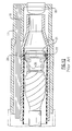
- FIG. 3A there is illustrated a first embodiment of a one-piece miniature wire connector 60 in accordance with the present invention.
- the wire connector 60 includes a substantially non-conductive body 62 having a plurality of exterior parallel grooves 64 , and a layer of conductive plating 66 formed on at least a portion of each of the grooves.
- the non-conductive body 62 is preferably molded as an integral or one-piece member in which the parallel grooves 64 can be created by the mold or can be later formed by grinding or other known methods.
- One end of the non-conductive body 62 preferably has a tapered construction which allows the individual coaxial cables 12 of the transmission cable 33 to fall along a natural path on the outside of the supporting body 62 . This arrangement reduces the stiffness of the entire assembly which results in less strain on the cables and helps prevent them from breaking during use.
- the grooves 64 extend along a portion of the length of the supporting body 62 , though depending on the application the grooves may alternately other or the entirety thereof, the grooves serving to retain at least an axial portion of the individual coaxial cable wires.
- the coaxial cables 12 lie within the groove 64 such that a corresponding cable is at least partially embedded in the non-conductive body 62 .
- the layer of conductive plating 66 defines a conductive-portion, the layer being preferably formed from a metallic material, although any known electric conductor could be utilized.
- One purpose of the conductive plating layer 66 is to provide a connection that carries an electrical signal between the coaxial cable wire 12 and the hybrid leads of the imager assembly.
- the conductive plating layer 66 preferably takes the form of a printed circuit that electrically connects the respective conductive shields.
- the above-described layer 66 also provides a large bonding surface for the solder used to join the coaxial cables to the conductive portion of the supporting body 62 of the wire connector 60 .
- a pair of cross grooves 68 extend transversely at the proximal end of the grooves 64 .
- These cross grooves 68 may have a conductive layer 66 also, but vertical grooves and cross grooves do not have connecting conductive layers unless it is desired.
- the miniature wire connector 60 preferably includes a recess 79 formed in an upper surface of the supporting body 62 for fixedly retaining an electronic imager assembly 70 relative to the upper surface of the body.
- the electronic imager assembly 70 shown herein includes a cubic supporting block 72 comprising circuit boards 73 , some of each of which include electronic components (not shown) disposed on exterior surfaces thereof. Additional details relating to the electronic imager assembly are provided in commonly assigned U.S. Ser. No. 09/777,134 previously incorporated by reference.
- This recess 79 is preferably defined by at least one pair of substantially parallel attachment lugs 74 , each of which of each includes interior facing bonding surfaces 76 used for bonding to the hybrid circuit leads 75 of the imager assembly 70 .
- These bonding surfaces 76 are preferably formed as printed circuits.
- the grooves 66 extend upwardly along the outer surface of the supporting body 62 and terminate at the pair of attachment lugs 74 .
- the interior facing bonding surfaces 76 thus provide an electrical path between the grooves 66 and hybrid circuitry (such as an amplifier) located on the circuit boards 73 of the imager assembly 70 .
- the interior facing bonding surfaces 76 also serve to hold the imager assembly 70 in position by attachment to the hybrid circuit leads 75 .
- fine pitch imager leads 24 extending from between the imager and transparent window are also attached to the circuit boards 73 of the mounting block 72 .
- the recess 79 is sized to be substantially identical in shape to the imager assembly 70 , thereby allowing the attachment lugs 74 to securely fix the imager assembly in position and even further prevent movement of the imager assembly.
- the recess 79 can define any geometrical shape useful for securely fixing the imager assembly 70 in position. Securely anchoring the imager assembly 70 is critical in order to maintain focus of the imaging instrument.
- FIG. 3 B A variation of the wire connector 80 having a non-conductive supporting body 81 is shown in FIG. 3 B.
- the body 81 includes a plurality of exterior grooves 82 , each of the exterior grooves according to this embodiment including a transverse separating cross-groove 86 .
- the exterior grooves 82 are therefore separated into two regions, namely, upper groove regions 90 which are attached to the center conductor wires, and lower groove regions 94 used for attaching a ground braid of each coaxial cable.
- the cross-groove 86 can be filled with a conductor to form a grounding bus which is used to ground the conductive grounding braid of the coaxial cable (not shown in this FIG. 3B, but clearly shown in FIGS. 3A and 3C with regard to the wire connector 60 ).
- each of the non-conducting supporting bodies 60 , 80 may further include a lateral fixturing hole 98 extending through the entirety of the body for use during wire attachment.
- This lateral fixturing hole 98 serves a variety of functions, including storage of electrical components or alternate use in conjunction with a fixturing pin (not shown) to provide anchoring of the supporting body within the insertion portion of a videoized instrument.
- part of the insulating jacket 48 of the coaxial cable 12 is stripped away to expose the individual conductive shield 44 .
- the insulative jacket 48 tightly holds the individual conductive shield 44 together.
- Portions of the coaxial cables 12 are then placed within and connected to the grooves 64 .
- the center conductor wire 19 of each cable 12 is preferably soldered to the conductive-portion 66
- the insulative jacket 48 is preferably attached to the non-conductive portion of the outer surface of the supporting body 62 .
- each coaxial cable 12 When attached, the center conductor wire 19 of each coaxial cable 12 extends slightly past the end of the supporting body 60 , and may also be soldered to the adjacent hybrid leads 75 to connect the leads to a signal processing portion of the unit.
- the hybrid circuitry typically includes amplifiers that drive the image signals along the transmission cable 33 to the signal processing portion. If necessary, however, the conductive shield 44 can also be soldered to the transverse cross groove 68 which serves as a grounding bus for each of the conductive shielding portions, as shown in FIG. 3 D.
- this embodiment of the present invention is advantageous in that a one-piece conductive portion has a layer of conductive plating along each groove 64 to allow the center conductor wire 19 to be soldered to the conductive portion 66 . Soldering the wires 19 provides strain relief far superior to that of known connectors. Moreover, the imager assembly 70 is fully retained by the wire connector 60 . The attachment lugs 74 of the supporting body 62 of the described wire connector 60 maintain accurate alignment of the imager assembly 70 . Moreover and as noted above, the tapered design of the supporting body 62 allows each individual coaxial cable 12 to fall along the outer surface of the supporting body more naturally.
- the grooves 64 allow each entire coaxial cable 12 to rest within the outer surface of the supporting body 62 , and further because the imager assembly 70 is disposed on part of the supporting body 62 , the region where the center conductor wire 19 connects to the imager, the assembly is less stiff and therefore, has greater flexibility.
- the design also helps to prevent the center conductor wire 19 from becoming detached or separated, and strain placed on the coaxial cables 12 is substantially relieved.
- the stiffness of each coaxial cable 12 is substantially reduced. As a result, any coaxial cable connections are less likely to break while the attached imager assembly 70 is less likely to shift or become misaligned.
- the miniature wire connector 108 includes a substantially non-conducting supporting body 112 , the body having retaining means 116 for retaining an electronic imager assembly on a first end surface 122 thereof, and a plurality of exteriorly disposed grooves 124 extending along exterior surfaces 128 of the body.
- Each of the grooves 124 have an electrically conductive portion 132 for retaining at least a portion of at least one coaxial cable wire.
- the tapered, substantially non-conducting supporting body 112 includes at least one socket 136 for receiving at least one center conductor of a coaxial cable, and preferably includes a plurality of sockets 138 as shown in FIGS. 4, 5 , and 8 .
- the retaining means 116 advantageously allows for axial adjustment of a lens cell with respect to the first end surface to focus the imager.
- the socket 136 can be any known means for connecting or terminating a coaxial cable. As shown in FIG. 8, a similar connector may also include a socket 138 for each center conductor.
- the sockets 138 can further include a locking or retaining mechanism for attachment to the outer sheath or conductive shielding of the coaxial cable to help ensure that the center conductor remains connected within the socket.
- a third embodiment of a miniature wire connector 140 includes a substantially non-conducting center-conductor termination plate 144 , and retaining means 148 defined on exterior edges of the plate 144 for retaining an electronic imager assembly 150 thereon.
- a plurality of grooves 152 are disposed along the exterior surfaces of the center-conductor termination plate 144 .
- Each of the grooves 152 have an electrically conductive portion 156 for retaining at least one center conductor wire of at least one individual coaxial cable.
- a shield termination plate 160 having a plurality of adjacent grooves 164 disposed along exterior surfaces 168 retains an axial portion of a corresponding coaxial cable.
- the plurality of adjacent grooves 164 each retain the outer sheath of the coaxial cables in the connector.
- An insulating spacer plate 170 may optionally be positioned between the substantially non-conducting center-conductor termination plate 144 and the shield termination plate 160 .
- each of the adjacent grooves 164 may have an electrically conductive portion 174 for grounding the conductive shielding of the cable.
- Each of the adjacent grooves 164 may be electrically connected to ground via a grounding pin 172 connected between the substantially non-conducting center-conductor termination plate 144 and the shield termination plate 160 .
- a surface 164 of the shield termination plate 160 has at least one grounding bus 168 thereon for terminating the conductive shielding 44 .
- This grounding bus 168 is preferably printed on the shield termination plate 160 as a printed circuit, which electrically connects the conductive shield 44 of each coaxial cable.
Abstract
Description
Claims (18)
Priority Applications (1)
| Application Number | Priority Date | Filing Date | Title |
|---|---|---|---|
| US09/778,296 US6494739B1 (en) | 2001-02-07 | 2001-02-07 | Miniature connector with improved strain relief for an imager assembly |
Applications Claiming Priority (1)
| Application Number | Priority Date | Filing Date | Title |
|---|---|---|---|
| US09/778,296 US6494739B1 (en) | 2001-02-07 | 2001-02-07 | Miniature connector with improved strain relief for an imager assembly |
Publications (1)
| Publication Number | Publication Date |
|---|---|
| US6494739B1 true US6494739B1 (en) | 2002-12-17 |
Family
ID=25112866
Family Applications (1)
| Application Number | Title | Priority Date | Filing Date |
|---|---|---|---|
| US09/778,296 Expired - Lifetime US6494739B1 (en) | 2001-02-07 | 2001-02-07 | Miniature connector with improved strain relief for an imager assembly |
Country Status (1)
| Country | Link |
|---|---|
| US (1) | US6494739B1 (en) |
Cited By (38)
| Publication number | Priority date | Publication date | Assignee | Title |
|---|---|---|---|---|
| US20040183900A1 (en) * | 2003-03-20 | 2004-09-23 | Everest Vit | Method and system for automatically detecting defects in remote video inspection applications |
| US20040233318A1 (en) * | 2003-05-20 | 2004-11-25 | Everest Vit | Imager cover-glass mounting |
| US20050191867A1 (en) * | 2002-08-28 | 2005-09-01 | Gerhard Birkenmaier | Apparatus for the connection of an electrical or electronic component with at least one electrical connector |
| US20060072903A1 (en) * | 2001-02-22 | 2006-04-06 | Everest Vit, Inc. | Method and system for storing calibration data within image files |
| US20070070340A1 (en) * | 2005-06-22 | 2007-03-29 | Karpen Thomas W | Remote video inspection system integrating audio communication functionality |
| US20070091183A1 (en) * | 2005-10-21 | 2007-04-26 | Ge Inspection Technologies, Lp | Method and apparatus for adapting the operation of a remote viewing device to correct optical misalignment |
| US20070187574A1 (en) * | 2006-02-13 | 2007-08-16 | Ge Inspection Technologies, Lp | Electronic imaging device with photosensor arrays |
| US20070225931A1 (en) * | 2006-03-27 | 2007-09-27 | Ge Inspection Technologies, Lp | Inspection apparatus for inspecting articles |
| US20080151046A1 (en) * | 2006-12-22 | 2008-06-26 | Ge Inspection Technologies, Lp | Heat protection systems and methods for remote viewing devices |
| US7422559B2 (en) | 2004-06-16 | 2008-09-09 | Ge Inspection Technologies, Lp | Borescope comprising fluid supply system |
| US20080254672A1 (en) * | 2002-07-23 | 2008-10-16 | Adc Gmbh | Plug-in connector for a connector-ended cable |
| US20090109429A1 (en) * | 2007-10-26 | 2009-04-30 | Joshua Lynn Scott | Inspection apparatus having heat sink assembly |
| EP2140802A1 (en) * | 2008-07-01 | 2010-01-06 | Fujifilm Corporation | Electronic endoscope |
| US7819798B2 (en) | 2005-06-24 | 2010-10-26 | Ge Inspection Technologies, Lp | Insertion tube storage carousel |
| US20110052133A1 (en) * | 2009-08-31 | 2011-03-03 | 3M Innovative Properties Company | Fiber organizer tray and telecommunications enclosure |
| WO2011025869A2 (en) * | 2009-08-31 | 2011-03-03 | 3M Innovative Properties Company | Strain relief device |
| US7902990B2 (en) | 2007-10-26 | 2011-03-08 | Ge Inspection Technologies, Lp | Battery and power management for industrial inspection handset |
| EP2434748A1 (en) | 2010-09-27 | 2012-03-28 | Karl Storz GmbH & Co. KG | Image capturing module and method for manufacturing the same |
| US8213676B2 (en) | 2006-12-20 | 2012-07-03 | Ge Inspection Technologies Lp | Inspection apparatus method and apparatus comprising motion responsive control |
| US8253782B2 (en) | 2007-10-26 | 2012-08-28 | Ge Inspection Technologies, Lp | Integrated storage for industrial inspection handset |
| US8310604B2 (en) | 2007-10-26 | 2012-11-13 | GE Sensing & Inspection Technologies, LP | Visual inspection apparatus having light source bank |
| US8514278B2 (en) | 2006-12-29 | 2013-08-20 | Ge Inspection Technologies Lp | Inspection apparatus having illumination assembly |
| US20130219715A1 (en) * | 2005-02-17 | 2013-08-29 | Greene, Tweed Of Delaware, Inc. | Method of forming connector with isolated conductive paths |
| US20130258183A1 (en) * | 2012-03-30 | 2013-10-03 | Takatoshi Kamei | Support, imaging apparatus, and connection method for an imaging apparatus |
| US8625434B2 (en) | 2006-12-29 | 2014-01-07 | Ge Inspection Technologies Lp | IP based voice communication enabled inspection system |
| CN103868541A (en) * | 2012-12-07 | 2014-06-18 | 通用电气公司 | Borescope with navigation function |
| US8810636B2 (en) | 2006-12-20 | 2014-08-19 | Ge Inspection Technologies, Lp | Inspection apparatus method and apparatus comprising selective frame output |
| US20160018602A1 (en) * | 2014-07-18 | 2016-01-21 | Biosense Webster (Israel) Ltd. | Electro-optical connector with hot electrical contact protection |
| US9519814B2 (en) | 2009-06-12 | 2016-12-13 | Hand Held Products, Inc. | Portable data terminal |
| US20170251913A1 (en) * | 2016-03-01 | 2017-09-07 | Karl Storz Endovision, Inc. | Compact image sensor module and method of assembly for image sensor modules |
| US10291850B2 (en) | 2006-12-20 | 2019-05-14 | General Electric Company | Inspection apparatus method and apparatus comprising selective frame output |
| US20200221598A1 (en) * | 2019-01-09 | 2020-07-09 | Altek Biotechnology Corporation | Microelectronic device and circuit board thereof element thereof |
| US10942964B2 (en) | 2009-02-02 | 2021-03-09 | Hand Held Products, Inc. | Apparatus and method of embedding meta-data in a captured image |
| CN114447685A (en) * | 2022-02-18 | 2022-05-06 | 哈尔滨工业大学 | Electromagnetic impact resistant water-electricity separation integrated wire connector for water-cooling coil |
| US11330972B2 (en) * | 2018-01-11 | 2022-05-17 | Olympus Corporation | Oblique-viewing endoscope |
| US20230047240A1 (en) * | 2021-08-13 | 2023-02-16 | Altek Biotechnology Corporation | Electronic device and electronic system |
| EP4140390A1 (en) * | 2021-08-24 | 2023-03-01 | Altek Biotechnology Corporation | Surface mounted assembly and related endoscope |
| US20230165449A1 (en) * | 2021-11-26 | 2023-06-01 | Altek Biotechnology Corporation | Endoscopic image capturing assembly and endoscopic devce therewith |
Citations (24)
| Publication number | Priority date | Publication date | Assignee | Title |
|---|---|---|---|---|
| US4090764A (en) | 1973-12-19 | 1978-05-23 | The Deutsch Company Electronic Components Division | Modular electrical connector |
| US4210380A (en) | 1978-11-08 | 1980-07-01 | Western Electric Company, Inc. | Cable connector housing having strain relief system |
| US4283106A (en) | 1980-02-01 | 1981-08-11 | Amp Incorporated | Symmetrical connector for solar panel arrays |
| US4773396A (en) | 1986-08-11 | 1988-09-27 | Olympus Optical Co., Ltd. | Endoscope |
| US4921447A (en) | 1989-05-17 | 1990-05-01 | Amp Incorporated | Terminating a shield of a malleable coaxial cable |
| US4974075A (en) | 1987-08-11 | 1990-11-27 | Olympus Optical Co., Ltd. | Image pickup apparatus having connector capable of separately shielding grouped electrical connections |
| US4973262A (en) * | 1988-09-22 | 1990-11-27 | Krone Aktiengeselschaft | Conduct member for electrical conductors |
| US4993968A (en) | 1989-03-02 | 1991-02-19 | Precision Interconnect Corporation | Economical connector system for an array of conductors |
| US5010876A (en) | 1986-06-02 | 1991-04-30 | Smith & Nephew Dyonics, Inc. | Arthroscopic surgical practice |
| US5151039A (en) | 1990-04-06 | 1992-09-29 | Advanced Interconnections Corporation | Integrated circuit adapter having gullwing-shaped leads |
| US5190472A (en) | 1992-03-24 | 1993-03-02 | W. L. Gore & Associates, Inc. | Miniaturized high-density coaxial connector system with staggered grouper modules |
| US5194020A (en) | 1991-06-17 | 1993-03-16 | W. L. Gore & Associates, Inc. | High-density coaxial interconnect system |
| US5385490A (en) | 1993-08-24 | 1995-01-31 | The Whitaker Corporation | Modular connector for use with multi-conductor cable |
| US5427087A (en) | 1990-11-26 | 1995-06-27 | Asahi Kogaku Kogyo Kabushiki Kaisha | Structure of the distal end portion of an endoscope |
| US5454366A (en) | 1990-11-27 | 1995-10-03 | Asashi Kogaku Kogyo Kabushiki Kaisha | Endoscope distal end with folded circuit board |
| US5501612A (en) | 1994-06-17 | 1996-03-26 | The Whitaker Corporation | Low profile board-to-board electrical connector |
| US5571035A (en) | 1994-10-31 | 1996-11-05 | The Whitaker Corporation | Divergent load bar |
| US5609499A (en) | 1995-08-15 | 1997-03-11 | Hon Hai Precision Ind. Co., Ltd. | Cable connector assembly with reinforcement structure |
| US5679008A (en) | 1994-12-15 | 1997-10-21 | Kel Corporation | Electrical connector |
| US5734418A (en) | 1996-07-17 | 1998-03-31 | Welch Allyn, Inc. | Endoscope with tab imager package |
| US5754313A (en) | 1996-07-17 | 1998-05-19 | Welch Allyn, Inc. | Imager assembly |
| US5768771A (en) | 1996-03-01 | 1998-06-23 | Molex Incorporated | System for terminating the shield of a high speed cable |
| US5855493A (en) | 1996-03-11 | 1999-01-05 | The Whitaker Corporation | Electrical connector strain relief with shield ground for multiple cables |
| US5857963A (en) | 1996-07-17 | 1999-01-12 | Welch Allyn, Inc. | Tab imager assembly for use in an endoscope |
-
2001
- 2001-02-07 US US09/778,296 patent/US6494739B1/en not_active Expired - Lifetime
Patent Citations (24)
| Publication number | Priority date | Publication date | Assignee | Title |
|---|---|---|---|---|
| US4090764A (en) | 1973-12-19 | 1978-05-23 | The Deutsch Company Electronic Components Division | Modular electrical connector |
| US4210380A (en) | 1978-11-08 | 1980-07-01 | Western Electric Company, Inc. | Cable connector housing having strain relief system |
| US4283106A (en) | 1980-02-01 | 1981-08-11 | Amp Incorporated | Symmetrical connector for solar panel arrays |
| US5010876A (en) | 1986-06-02 | 1991-04-30 | Smith & Nephew Dyonics, Inc. | Arthroscopic surgical practice |
| US4773396A (en) | 1986-08-11 | 1988-09-27 | Olympus Optical Co., Ltd. | Endoscope |
| US4974075A (en) | 1987-08-11 | 1990-11-27 | Olympus Optical Co., Ltd. | Image pickup apparatus having connector capable of separately shielding grouped electrical connections |
| US4973262A (en) * | 1988-09-22 | 1990-11-27 | Krone Aktiengeselschaft | Conduct member for electrical conductors |
| US4993968A (en) | 1989-03-02 | 1991-02-19 | Precision Interconnect Corporation | Economical connector system for an array of conductors |
| US4921447A (en) | 1989-05-17 | 1990-05-01 | Amp Incorporated | Terminating a shield of a malleable coaxial cable |
| US5151039A (en) | 1990-04-06 | 1992-09-29 | Advanced Interconnections Corporation | Integrated circuit adapter having gullwing-shaped leads |
| US5427087A (en) | 1990-11-26 | 1995-06-27 | Asahi Kogaku Kogyo Kabushiki Kaisha | Structure of the distal end portion of an endoscope |
| US5454366A (en) | 1990-11-27 | 1995-10-03 | Asashi Kogaku Kogyo Kabushiki Kaisha | Endoscope distal end with folded circuit board |
| US5194020A (en) | 1991-06-17 | 1993-03-16 | W. L. Gore & Associates, Inc. | High-density coaxial interconnect system |
| US5190472A (en) | 1992-03-24 | 1993-03-02 | W. L. Gore & Associates, Inc. | Miniaturized high-density coaxial connector system with staggered grouper modules |
| US5385490A (en) | 1993-08-24 | 1995-01-31 | The Whitaker Corporation | Modular connector for use with multi-conductor cable |
| US5501612A (en) | 1994-06-17 | 1996-03-26 | The Whitaker Corporation | Low profile board-to-board electrical connector |
| US5571035A (en) | 1994-10-31 | 1996-11-05 | The Whitaker Corporation | Divergent load bar |
| US5679008A (en) | 1994-12-15 | 1997-10-21 | Kel Corporation | Electrical connector |
| US5609499A (en) | 1995-08-15 | 1997-03-11 | Hon Hai Precision Ind. Co., Ltd. | Cable connector assembly with reinforcement structure |
| US5768771A (en) | 1996-03-01 | 1998-06-23 | Molex Incorporated | System for terminating the shield of a high speed cable |
| US5855493A (en) | 1996-03-11 | 1999-01-05 | The Whitaker Corporation | Electrical connector strain relief with shield ground for multiple cables |
| US5734418A (en) | 1996-07-17 | 1998-03-31 | Welch Allyn, Inc. | Endoscope with tab imager package |
| US5754313A (en) | 1996-07-17 | 1998-05-19 | Welch Allyn, Inc. | Imager assembly |
| US5857963A (en) | 1996-07-17 | 1999-01-12 | Welch Allyn, Inc. | Tab imager assembly for use in an endoscope |
Cited By (63)
| Publication number | Priority date | Publication date | Assignee | Title |
|---|---|---|---|---|
| US20060072903A1 (en) * | 2001-02-22 | 2006-04-06 | Everest Vit, Inc. | Method and system for storing calibration data within image files |
| US8043095B2 (en) * | 2002-07-23 | 2011-10-25 | Adc Gmbh | Plug-in connector for a connector-ended cable |
| US20080254672A1 (en) * | 2002-07-23 | 2008-10-16 | Adc Gmbh | Plug-in connector for a connector-ended cable |
| US20050191867A1 (en) * | 2002-08-28 | 2005-09-01 | Gerhard Birkenmaier | Apparatus for the connection of an electrical or electronic component with at least one electrical connector |
| US20040183900A1 (en) * | 2003-03-20 | 2004-09-23 | Everest Vit | Method and system for automatically detecting defects in remote video inspection applications |
| US20040233318A1 (en) * | 2003-05-20 | 2004-11-25 | Everest Vit | Imager cover-glass mounting |
| US6953432B2 (en) | 2003-05-20 | 2005-10-11 | Everest Vit, Inc. | Imager cover-glass mounting |
| US7422559B2 (en) | 2004-06-16 | 2008-09-09 | Ge Inspection Technologies, Lp | Borescope comprising fluid supply system |
| US9705235B2 (en) | 2005-02-17 | 2017-07-11 | Halliburton Energy Services, Inc. | Apparatus having a connector with isolated conductive paths |
| US8844127B2 (en) | 2005-02-17 | 2014-09-30 | Halliburton Energy Services, Inc. | Apparatus having a connector with isolated conductive paths |
| US8756807B2 (en) * | 2005-02-17 | 2014-06-24 | Halliburton Energy Services, Inc. | Method of forming connector with isolated conductive paths |
| US20130219715A1 (en) * | 2005-02-17 | 2013-08-29 | Greene, Tweed Of Delaware, Inc. | Method of forming connector with isolated conductive paths |
| US7956888B2 (en) | 2005-06-22 | 2011-06-07 | Ge Inspection Technologies, Lp | Remote video inspection system integrating audio communication functionality |
| US20070070340A1 (en) * | 2005-06-22 | 2007-03-29 | Karpen Thomas W | Remote video inspection system integrating audio communication functionality |
| US7819798B2 (en) | 2005-06-24 | 2010-10-26 | Ge Inspection Technologies, Lp | Insertion tube storage carousel |
| US20070091183A1 (en) * | 2005-10-21 | 2007-04-26 | Ge Inspection Technologies, Lp | Method and apparatus for adapting the operation of a remote viewing device to correct optical misalignment |
| US20070187574A1 (en) * | 2006-02-13 | 2007-08-16 | Ge Inspection Technologies, Lp | Electronic imaging device with photosensor arrays |
| US7679041B2 (en) | 2006-02-13 | 2010-03-16 | Ge Inspection Technologies, Lp | Electronic imaging device with photosensor arrays |
| US8368749B2 (en) | 2006-03-27 | 2013-02-05 | Ge Inspection Technologies Lp | Article inspection apparatus |
| US8310533B2 (en) | 2006-03-27 | 2012-11-13 | GE Sensing & Inspection Technologies, LP | Inspection apparatus for inspecting articles |
| US20070225931A1 (en) * | 2006-03-27 | 2007-09-27 | Ge Inspection Technologies, Lp | Inspection apparatus for inspecting articles |
| US8810636B2 (en) | 2006-12-20 | 2014-08-19 | Ge Inspection Technologies, Lp | Inspection apparatus method and apparatus comprising selective frame output |
| US9621808B2 (en) | 2006-12-20 | 2017-04-11 | General Electric Company | Inspection apparatus method and apparatus comprising selective frame output |
| US8213676B2 (en) | 2006-12-20 | 2012-07-03 | Ge Inspection Technologies Lp | Inspection apparatus method and apparatus comprising motion responsive control |
| US10291850B2 (en) | 2006-12-20 | 2019-05-14 | General Electric Company | Inspection apparatus method and apparatus comprising selective frame output |
| US20080151046A1 (en) * | 2006-12-22 | 2008-06-26 | Ge Inspection Technologies, Lp | Heat protection systems and methods for remote viewing devices |
| US8118733B2 (en) | 2006-12-22 | 2012-02-21 | Ge Inspection Technologies, Lp | Heat protection systems and methods for remote viewing devices |
| US8514278B2 (en) | 2006-12-29 | 2013-08-20 | Ge Inspection Technologies Lp | Inspection apparatus having illumination assembly |
| US8625434B2 (en) | 2006-12-29 | 2014-01-07 | Ge Inspection Technologies Lp | IP based voice communication enabled inspection system |
| US8310604B2 (en) | 2007-10-26 | 2012-11-13 | GE Sensing & Inspection Technologies, LP | Visual inspection apparatus having light source bank |
| US20090109429A1 (en) * | 2007-10-26 | 2009-04-30 | Joshua Lynn Scott | Inspection apparatus having heat sink assembly |
| US8253782B2 (en) | 2007-10-26 | 2012-08-28 | Ge Inspection Technologies, Lp | Integrated storage for industrial inspection handset |
| US7902990B2 (en) | 2007-10-26 | 2011-03-08 | Ge Inspection Technologies, Lp | Battery and power management for industrial inspection handset |
| US8767060B2 (en) | 2007-10-26 | 2014-07-01 | Ge Inspection Technologies, Lp | Inspection apparatus having heat sink assembly |
| EP2140802A1 (en) * | 2008-07-01 | 2010-01-06 | Fujifilm Corporation | Electronic endoscope |
| US10942964B2 (en) | 2009-02-02 | 2021-03-09 | Hand Held Products, Inc. | Apparatus and method of embedding meta-data in a captured image |
| US11042793B2 (en) | 2009-06-12 | 2021-06-22 | Hand Held Products, Inc. | Portable data terminal |
| US9959495B2 (en) | 2009-06-12 | 2018-05-01 | Hand Held Products, Inc. | Portable data terminal |
| US9519814B2 (en) | 2009-06-12 | 2016-12-13 | Hand Held Products, Inc. | Portable data terminal |
| US8754331B2 (en) | 2009-08-31 | 2014-06-17 | 3M Innovative Properties Company | Strain relief device |
| WO2011025869A2 (en) * | 2009-08-31 | 2011-03-03 | 3M Innovative Properties Company | Strain relief device |
| US20110052133A1 (en) * | 2009-08-31 | 2011-03-03 | 3M Innovative Properties Company | Fiber organizer tray and telecommunications enclosure |
| WO2011025869A3 (en) * | 2009-08-31 | 2011-05-05 | 3M Innovative Properties Company | Strain relief device |
| US8633429B2 (en) | 2010-09-27 | 2014-01-21 | Karl Storz Gmbh & Co. Kg | Image pick-up module with contact point circuit connection |
| DE102010047288A1 (en) * | 2010-09-27 | 2012-03-29 | Karl Storz Gmbh & Co. Kg | Image sensor module and method for producing an image sensor module |
| EP2434748A1 (en) | 2010-09-27 | 2012-03-28 | Karl Storz GmbH & Co. KG | Image capturing module and method for manufacturing the same |
| US20130258183A1 (en) * | 2012-03-30 | 2013-10-03 | Takatoshi Kamei | Support, imaging apparatus, and connection method for an imaging apparatus |
| US8988600B2 (en) * | 2012-03-30 | 2015-03-24 | Kabushiki Kaisha Toshiba | Support, imaging apparatus, and connection method for an imaging apparatus |
| CN103868541A (en) * | 2012-12-07 | 2014-06-18 | 通用电气公司 | Borescope with navigation function |
| US20160018602A1 (en) * | 2014-07-18 | 2016-01-21 | Biosense Webster (Israel) Ltd. | Electro-optical connector with hot electrical contact protection |
| US9784922B2 (en) * | 2014-07-18 | 2017-10-10 | Biosense Webster (Israel) Ltd | Electro-optical connector with hot electrical contact protection |
| US20170251913A1 (en) * | 2016-03-01 | 2017-09-07 | Karl Storz Endovision, Inc. | Compact image sensor module and method of assembly for image sensor modules |
| US10485404B2 (en) * | 2016-03-01 | 2019-11-26 | Karl Storz Endovision, Inc. | Compact image sensor module and method of assembly for image sensor modules |
| US11330972B2 (en) * | 2018-01-11 | 2022-05-17 | Olympus Corporation | Oblique-viewing endoscope |
| US11317531B2 (en) * | 2019-01-09 | 2022-04-26 | Altek Biotechnology Corporation | Microelectronic device and circuit board thereof |
| US20200221598A1 (en) * | 2019-01-09 | 2020-07-09 | Altek Biotechnology Corporation | Microelectronic device and circuit board thereof element thereof |
| US20230047240A1 (en) * | 2021-08-13 | 2023-02-16 | Altek Biotechnology Corporation | Electronic device and electronic system |
| US11586030B1 (en) * | 2021-08-13 | 2023-02-21 | Altek Biotechnology Corporation | Electronic device and electronic system |
| EP4140390A1 (en) * | 2021-08-24 | 2023-03-01 | Altek Biotechnology Corporation | Surface mounted assembly and related endoscope |
| US11832799B2 (en) | 2021-08-24 | 2023-12-05 | Altek Biotechnology Corporation | Surface mounted assembly and related endoscope |
| US20230165449A1 (en) * | 2021-11-26 | 2023-06-01 | Altek Biotechnology Corporation | Endoscopic image capturing assembly and endoscopic devce therewith |
| CN114447685A (en) * | 2022-02-18 | 2022-05-06 | 哈尔滨工业大学 | Electromagnetic impact resistant water-electricity separation integrated wire connector for water-cooling coil |
| CN114447685B (en) * | 2022-02-18 | 2022-10-11 | 哈尔滨工业大学 | Electromagnetic impact resistant water-electricity separation integrated wire connector for water-cooling coil |
Similar Documents
| Publication | Publication Date | Title |
|---|---|---|
| US6494739B1 (en) | Miniature connector with improved strain relief for an imager assembly | |
| US4998182A (en) | Connector for optical sensor | |
| US4677471A (en) | Endoscope | |
| JP4366356B2 (en) | Image pickup module and image pickup module assembling method | |
| US4831456A (en) | Imaging apparatus using a solid-state imaging element having a substrate | |
| CN103185960B (en) | Image mechanism and endoscope apparatus | |
| US11172812B2 (en) | Endoscope | |
| CN106886089B (en) | Endoscope with a detachable handle | |
| US8488928B2 (en) | Opto-electro hybrid harness and method of manufacturing the same | |
| JP3905152B2 (en) | Imaging device for endoscope | |
| JP2000083896A (en) | Imaging device for endoscope | |
| JPH11295617A (en) | Image pickup device | |
| JPH0435474A (en) | Solid-state image pickup element | |
| JP3689188B2 (en) | Imaging device | |
| JP3548467B2 (en) | Imaging device | |
| US20200405136A1 (en) | Endoscope | |
| JPH09173287A (en) | Electronic endoscope | |
| JP3811318B2 (en) | Imaging device and endoscope provided with imaging device | |
| JPH1099267A (en) | Imaging device | |
| JPH10248803A (en) | Image pick-up device | |
| US10888217B2 (en) | Imaging module applicable to head-swing endoscope | |
| JPH065765Y2 (en) | Electronic endoscope | |
| JP4054117B2 (en) | Electronic endoscope | |
| JPH1028672A (en) | Image pick-up device | |
| JP3706324B2 (en) | Imaging device |
Legal Events
| Date | Code | Title | Description |
|---|---|---|---|
| AS | Assignment |
Owner name: WELCH ALLYN, INC., NEW YORK Free format text: ASSIGNMENT OF ASSIGNORS INTEREST;ASSIGNORS:VIVENZIO, ROBERT L.;GRECCO, JAMES EDWARD;BURDICK, KENNETH J.;AND OTHERS;REEL/FRAME:011556/0800 Effective date: 20010130 |
|
| STCF | Information on status: patent grant |
Free format text: PATENTED CASE |
|
| AS | Assignment |
Owner name: EVEREST VIT, INC., NEW JERSEY Free format text: ASSIGNMENT OF ASSIGNORS INTEREST;ASSIGNOR:WELCH ALLYN, INC.;REEL/FRAME:015698/0980 Effective date: 20040602 |
|
| FPAY | Fee payment |
Year of fee payment: 4 |
|
| AS | Assignment |
Owner name: GE INSPECTION TECHNOLOGIES, LP, PENNSYLVANIA Free format text: ASSIGNMENT OF ASSIGNORS INTEREST;ASSIGNOR:EVEREST VIT, INC.;REEL/FRAME:018047/0642 Effective date: 20060331 |
|
| FPAY | Fee payment |
Year of fee payment: 8 |
|
| FPAY | Fee payment |
Year of fee payment: 12 |