US6499366B1 - Sample feeder - Google Patents
Sample feeder Download PDFInfo
- Publication number
- US6499366B1 US6499366B1 US09/144,578 US14457898A US6499366B1 US 6499366 B1 US6499366 B1 US 6499366B1 US 14457898 A US14457898 A US 14457898A US 6499366 B1 US6499366 B1 US 6499366B1
- Authority
- US
- United States
- Prior art keywords
- sample container
- stack
- station
- sample
- transporter
- Prior art date
- Legal status (The legal status is an assumption and is not a legal conclusion. Google has not performed a legal analysis and makes no representation as to the accuracy of the status listed.)
- Expired - Fee Related
Links
Images


Classifications
-
- G—PHYSICS
- G01—MEASURING; TESTING
- G01N—INVESTIGATING OR ANALYSING MATERIALS BY DETERMINING THEIR CHEMICAL OR PHYSICAL PROPERTIES
- G01N21/00—Investigating or analysing materials by the use of optical means, i.e. using sub-millimetre waves, infrared, visible or ultraviolet light
- G01N21/75—Systems in which material is subjected to a chemical reaction, the progress or the result of the reaction being investigated
- G01N21/76—Chemiluminescence; Bioluminescence
-
- B—PERFORMING OPERATIONS; TRANSPORTING
- B01—PHYSICAL OR CHEMICAL PROCESSES OR APPARATUS IN GENERAL
- B01L—CHEMICAL OR PHYSICAL LABORATORY APPARATUS FOR GENERAL USE
- B01L9/00—Supporting devices; Holding devices
- B01L9/52—Supports specially adapted for flat sample carriers, e.g. for plates, slides, chips
- B01L9/523—Supports specially adapted for flat sample carriers, e.g. for plates, slides, chips for multisample carriers, e.g. used for microtitration plates
-
- B—PERFORMING OPERATIONS; TRANSPORTING
- B82—NANOTECHNOLOGY
- B82Y—SPECIFIC USES OR APPLICATIONS OF NANOSTRUCTURES; MEASUREMENT OR ANALYSIS OF NANOSTRUCTURES; MANUFACTURE OR TREATMENT OF NANOSTRUCTURES
- B82Y15/00—Nanotechnology for interacting, sensing or actuating, e.g. quantum dots as markers in protein assays or molecular motors
-
- B—PERFORMING OPERATIONS; TRANSPORTING
- B01—PHYSICAL OR CHEMICAL PROCESSES OR APPARATUS IN GENERAL
- B01J—CHEMICAL OR PHYSICAL PROCESSES, e.g. CATALYSIS OR COLLOID CHEMISTRY; THEIR RELEVANT APPARATUS
- B01J2219/00—Chemical, physical or physico-chemical processes in general; Their relevant apparatus
- B01J2219/00274—Sequential or parallel reactions; Apparatus and devices for combinatorial chemistry or for making arrays; Chemical library technology
- B01J2219/00277—Apparatus
- B01J2219/00279—Features relating to reactor vessels
- B01J2219/00306—Reactor vessels in a multiple arrangement
- B01J2219/00313—Reactor vessels in a multiple arrangement the reactor vessels being formed by arrays of wells in blocks
- B01J2219/00315—Microtiter plates
- B01J2219/00317—Microwell devices, i.e. having large numbers of wells
-
- B—PERFORMING OPERATIONS; TRANSPORTING
- B01—PHYSICAL OR CHEMICAL PROCESSES OR APPARATUS IN GENERAL
- B01J—CHEMICAL OR PHYSICAL PROCESSES, e.g. CATALYSIS OR COLLOID CHEMISTRY; THEIR RELEVANT APPARATUS
- B01J2219/00—Chemical, physical or physico-chemical processes in general; Their relevant apparatus
- B01J2219/00274—Sequential or parallel reactions; Apparatus and devices for combinatorial chemistry or for making arrays; Chemical library technology
- B01J2219/00583—Features relative to the processes being carried out
- B01J2219/00603—Making arrays on substantially continuous surfaces
- B01J2219/00605—Making arrays on substantially continuous surfaces the compounds being directly bound or immobilised to solid supports
- B01J2219/0061—The surface being organic
-
- B—PERFORMING OPERATIONS; TRANSPORTING
- B01—PHYSICAL OR CHEMICAL PROCESSES OR APPARATUS IN GENERAL
- B01J—CHEMICAL OR PHYSICAL PROCESSES, e.g. CATALYSIS OR COLLOID CHEMISTRY; THEIR RELEVANT APPARATUS
- B01J2219/00—Chemical, physical or physico-chemical processes in general; Their relevant apparatus
- B01J2219/00274—Sequential or parallel reactions; Apparatus and devices for combinatorial chemistry or for making arrays; Chemical library technology
- B01J2219/00583—Features relative to the processes being carried out
- B01J2219/00603—Making arrays on substantially continuous surfaces
- B01J2219/00605—Making arrays on substantially continuous surfaces the compounds being directly bound or immobilised to solid supports
- B01J2219/00612—Making arrays on substantially continuous surfaces the compounds being directly bound or immobilised to solid supports the surface being inorganic
-
- B—PERFORMING OPERATIONS; TRANSPORTING
- B01—PHYSICAL OR CHEMICAL PROCESSES OR APPARATUS IN GENERAL
- B01J—CHEMICAL OR PHYSICAL PROCESSES, e.g. CATALYSIS OR COLLOID CHEMISTRY; THEIR RELEVANT APPARATUS
- B01J2219/00—Chemical, physical or physico-chemical processes in general; Their relevant apparatus
- B01J2219/00274—Sequential or parallel reactions; Apparatus and devices for combinatorial chemistry or for making arrays; Chemical library technology
- B01J2219/00583—Features relative to the processes being carried out
- B01J2219/00603—Making arrays on substantially continuous surfaces
- B01J2219/00659—Two-dimensional arrays
-
- B—PERFORMING OPERATIONS; TRANSPORTING
- B01—PHYSICAL OR CHEMICAL PROCESSES OR APPARATUS IN GENERAL
- B01J—CHEMICAL OR PHYSICAL PROCESSES, e.g. CATALYSIS OR COLLOID CHEMISTRY; THEIR RELEVANT APPARATUS
- B01J2219/00—Chemical, physical or physico-chemical processes in general; Their relevant apparatus
- B01J2219/00274—Sequential or parallel reactions; Apparatus and devices for combinatorial chemistry or for making arrays; Chemical library technology
- B01J2219/0068—Means for controlling the apparatus of the process
- B01J2219/00686—Automatic
- B01J2219/00691—Automatic using robots
-
- B—PERFORMING OPERATIONS; TRANSPORTING
- B01—PHYSICAL OR CHEMICAL PROCESSES OR APPARATUS IN GENERAL
- B01J—CHEMICAL OR PHYSICAL PROCESSES, e.g. CATALYSIS OR COLLOID CHEMISTRY; THEIR RELEVANT APPARATUS
- B01J2219/00—Chemical, physical or physico-chemical processes in general; Their relevant apparatus
- B01J2219/00274—Sequential or parallel reactions; Apparatus and devices for combinatorial chemistry or for making arrays; Chemical library technology
- B01J2219/0068—Means for controlling the apparatus of the process
- B01J2219/00702—Processes involving means for analysing and characterising the products
- B01J2219/00707—Processes involving means for analysing and characterising the products separated from the reactor apparatus
-
- B—PERFORMING OPERATIONS; TRANSPORTING
- B01—PHYSICAL OR CHEMICAL PROCESSES OR APPARATUS IN GENERAL
- B01L—CHEMICAL OR PHYSICAL LABORATORY APPARATUS FOR GENERAL USE
- B01L2300/00—Additional constructional details
- B01L2300/08—Geometry, shape and general structure
- B01L2300/0809—Geometry, shape and general structure rectangular shaped
- B01L2300/0829—Multi-well plates; Microtitration plates
-
- C—CHEMISTRY; METALLURGY
- C40—COMBINATORIAL TECHNOLOGY
- C40B—COMBINATORIAL CHEMISTRY; LIBRARIES, e.g. CHEMICAL LIBRARIES
- C40B60/00—Apparatus specially adapted for use in combinatorial chemistry or with libraries
- C40B60/14—Apparatus specially adapted for use in combinatorial chemistry or with libraries for creating libraries
-
- Y—GENERAL TAGGING OF NEW TECHNOLOGICAL DEVELOPMENTS; GENERAL TAGGING OF CROSS-SECTIONAL TECHNOLOGIES SPANNING OVER SEVERAL SECTIONS OF THE IPC; TECHNICAL SUBJECTS COVERED BY FORMER USPC CROSS-REFERENCE ART COLLECTIONS [XRACs] AND DIGESTS
- Y10—TECHNICAL SUBJECTS COVERED BY FORMER USPC
- Y10S—TECHNICAL SUBJECTS COVERED BY FORMER USPC CROSS-REFERENCE ART COLLECTIONS [XRACs] AND DIGESTS
- Y10S436/00—Chemistry: analytical and immunological testing
- Y10S436/807—Apparatus included in process claim, e.g. physical support structures
- Y10S436/809—Multifield plates or multicontainer arrays
-
- Y—GENERAL TAGGING OF NEW TECHNOLOGICAL DEVELOPMENTS; GENERAL TAGGING OF CROSS-SECTIONAL TECHNOLOGIES SPANNING OVER SEVERAL SECTIONS OF THE IPC; TECHNICAL SUBJECTS COVERED BY FORMER USPC CROSS-REFERENCE ART COLLECTIONS [XRACs] AND DIGESTS
- Y10—TECHNICAL SUBJECTS COVERED BY FORMER USPC
- Y10T—TECHNICAL SUBJECTS COVERED BY FORMER US CLASSIFICATION
- Y10T436/00—Chemistry: analytical and immunological testing
- Y10T436/11—Automated chemical analysis
- Y10T436/113332—Automated chemical analysis with conveyance of sample along a test line in a container or rack
- Y10T436/114165—Automated chemical analysis with conveyance of sample along a test line in a container or rack with step of insertion or removal from test line
-
- Y—GENERAL TAGGING OF NEW TECHNOLOGICAL DEVELOPMENTS; GENERAL TAGGING OF CROSS-SECTIONAL TECHNOLOGIES SPANNING OVER SEVERAL SECTIONS OF THE IPC; TECHNICAL SUBJECTS COVERED BY FORMER USPC CROSS-REFERENCE ART COLLECTIONS [XRACs] AND DIGESTS
- Y10—TECHNICAL SUBJECTS COVERED BY FORMER USPC
- Y10T—TECHNICAL SUBJECTS COVERED BY FORMER US CLASSIFICATION
- Y10T436/00—Chemistry: analytical and immunological testing
- Y10T436/11—Automated chemical analysis
- Y10T436/115831—Condition or time responsive
-
- Y—GENERAL TAGGING OF NEW TECHNOLOGICAL DEVELOPMENTS; GENERAL TAGGING OF CROSS-SECTIONAL TECHNOLOGIES SPANNING OVER SEVERAL SECTIONS OF THE IPC; TECHNICAL SUBJECTS COVERED BY FORMER USPC CROSS-REFERENCE ART COLLECTIONS [XRACs] AND DIGESTS
- Y10—TECHNICAL SUBJECTS COVERED BY FORMER USPC
- Y10T—TECHNICAL SUBJECTS COVERED BY FORMER US CLASSIFICATION
- Y10T436/00—Chemistry: analytical and immunological testing
- Y10T436/25—Chemistry: analytical and immunological testing including sample preparation
Definitions
- the invention relates to a device for high-throughput screening. More particularly, the invention relates to a device for automatically feeding microplates into an analyzer for high-throughput screening.
- High-throughput screening instruments are critical tools in the pharmaceutical research industry and in the process of discovering and developing new drugs.
- High-throughput analyzers are used to assess the efficacy of candidate drug compounds. Dramatic increases in the number of these compounds and in the number of targets against which they may be directed have created a bottleneck in the development of new drugs and a need for analyzers that can operate with a high degree of analytical flexibility and speed. Analytical flexibility and speed are necessary because high-throughput applications may involve repeating the same operations hundreds of thousands of times, greatly magnifying even the smallest shortcomings.
- microplates are generally rectangular containers that include a plurality of sample wells for holding a plurality of samples. Microplates enhance speed by reducing transit time between samples and reduce cost by employing small amounts of reagents.
- microplates also have a number of shortcomings. For example, microplates do not conform to any exact standard, so that their size, shape, and construction materials may vary, depending on vendor or batch.
- microplates may vary from opaque to transparent, so that analytical approaches developed for some microplates will not work for other microplates.
- preferred microplates may differ, depending on application.
- microplates may allot only a small volume for each sample, so that signal is reduced and sample is more easily spilled during transit.
- robots permit analyzers to run 24 hours a day.
- current robotic systems have a number of shortcomings.
- robots commonly are used to deliver samples to an analyzer for analysis.
- the robot typically must make separate trips to drop off a sample container, such as a microplate, before analysis, to retrieve the sample container after analysis, and then to drop off another sample container for analysis.
- the analyzer is idle during the time that the robot is retuning the analyzed microplate and bringing the new microplate.
- the total down time due to robotic transport may become quite significant.
- the present invention addresses these and other shortcomings by providing a sample feeder that includes (1) a first station that receives and initiates transport of a sample container into an analyzer for analysis, (2) a second station where the sample container is handed off to a transporter that carries the sample container to and from an examination site inside the analyzer, and (3) a third station that collects the sample container after examination.
- the sample feeder may include a singulation mechanism positioned at the first station and configured to separate a sample container from a stack of sample containers for transport to the analyzer, and/or a stacking mechanism positioned at the third station and configured to add a sample container to a stack of sample containers.
- the sample feeder further may include a preprocessing bin positioned at the first station for holding a stack of sample containers to be analyzed, and/or a postprocessing bin positioned at the third station for holding a stack of sample containers after they have been analyzed.
- the invention also provides a sample feeder that includes (1) a lifter configured to raise or lower a sample container relative to the bottom of a stack of sample containers, and (2) at least one latch having a pick portion, the latch being mounted so that the pick portion moves in and out of gaps between adjacently stacked sample containers in response to up and down movement of the lifter.
- the lifter and latch may be designed to remove a single sample container from the bottom of a stack of sample containers, or to add a single sample container to the bottom of a stack of sample containers.
- the latch may include a pick portion that is urged toward the bottom of the stack by gravity, a spring, or other mechanisms.
- the invention also provides a sample feeder that includes (1) a lifter configured to impart a raising or lowering motion to a sample container to transfer the sample container to or from a stack of sample containers, and (2) a drive motor configured to generate a driving motion, wherein the lifter includes a cam operatively connected to the drive motor and configured to convert the driving motion into the raising or lowering motion.
- the invention also provides an automated analyzer system that includes (1) an analyzer unit having an internal examination site, and (2) first and second external loading stations, the first external loading station configured to receive a sample container before analysis, the second external loading station configured to receive the sample container after analysis.
- the automated analyzer system may include a robot programmed to deliver a sample container to the first external loading station, and to retrieve a different sample container from the second loading station in the same trip.
- FIG. 1 is a partially exploded perspective view of an analyzer, showing a transporter and sample feeder constructed in accordance with the invention.
- FIG. 2 is a perspective view of the top of a transporter constructed in accordance with the invention.
- FIG. 3 is a perspective view of the bottom of the transporter shown in FIG. 2 .
- FIG. 4 is a partial cross-sectional view of the transporter shown in FIGS. 2 and 3, taken generally along the line 4 — 4 in FIG. 3 .
- FIG. 5 is a perspective view of a base platform and associated drive mechanisms for moving a transporter along X and Y axes relative to the base platform.
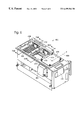
- FIG. 6 is a perspective view of a sample feeder constructed in accordance with the invention, with bins removed so that internal mechanisms of the sample feeder can be viewed.
- FIGS. 7A and 7B are cross-sectional views through a first (input) station of the sample feeder shown in FIG. 6, taken generally along the line 7 AB— 7 AB in FIG. 6 and showing latch and lifter cooperation to remove a microplate from the bottom of a stack.
- FIGS. 8A and 8B are cross-sectional views through a third (output) station of the sample feeder shown in FIG. 6, taken generally along the line 8 AB— 8 AB in FIG. 6 and showing latch and lifter cooperation to add a microplate to the bottom of a stack.
- FIG. 9 is a side elevation view of a lifter from the sample feeder shown in FIG. 6 .
- FIG. 1 shows a high-throughput luminescence analyzer 50 constructed in accordance with the invention.
- Components of the analyzer are maintained in a housing 100 , both for organization and for protection.
- Housing 100 is substantially rectangular and includes light-tight exterior top 102 , side 103 a-d , and bottom walls 104 that reduce background in luminescence measurements.
- the walls may include vents 106 to facilitate air flow through the analyzer and a transporter port 107 for sample input/output.
- Housing 100 also may include feet 108 to support the analyzer and to permit air flow between the analyzer and any support structure on which the analyzer is placed.
- Analyzer 50 is substantially automated.
- the analyzer is designed so that user interactions occur primarily through a control unit 110 , an electronic input/output panel 112 , and a break-out box (not shown), each of which supports a variety of input/output functions.
- the analyzer also is designed so that sample input/output occurs primarily through a transporter/stage 114 and an optional sample feeder 116 .
- Transporter 114 generally comprises any device for supporting a sample container. In analyzer 50 , transporter 114 moves between the interior and exterior of the analyzer, and may be used alone or together with sample feeder 116 for sample input/output.
- Sample feeder 116 generally comprises any device for automatically processing multiple samples.
- sample feeder 116 includes a first (input) station 118 for holding sample containers to be read, a third (output) station 120 for holding sample containers that have been read, and a second (direct transporter access) station 122 for inputting or outputting sample containers that bypasses the input and output stations.
- Input and output stations 118 , 120 accommodate preprocessing and postprocessing sample containers bins 124 , 126 that hold and organize stacks of sample containers before and after reading, respectively.
- Sample feeder 116 also may include a barcode reader 128 for automatically identifying labeled sample containers.
- the sample container generally comprises any container for holding at least one sample.
- Preferred sample containers include microplates.
- Other suitable sample containers include any sample containers having a shape and rigidity suitable for processing in an analyzer, such as slides or supported gels.
- FIGS. 2-5 show a stage, which generally comprises any mechanism for supporting a composition in a sample container for analysis by the analyzer.
- the stage includes a transporter 200 and base platform 300 .
- FIGS. 2-4 show transporter 200 , which includes a transporter body 202 and substantially parallel first and second transporter flanges 204 a,b that extend outward from transporter body 202 .
- First and second transporter flanges 204 a,b terminate in first and second transporter extensions 206 a,b that turn in toward one another without contacting one another.
- Transporter extensions 206 a,b may be joined by a connector portion 207 .
- Transporter body 202 , flanges 204 a,b , and extensions 206 a,b lie substantially in a plane and define a transporter cavity 208 that is larger than the expected peripheral dimension of any sample containers which the transporter is intended to support. The shape of this cavity is chosen to accommodate the shape of the preferred sample containers.
- cavity 208 is generally rectangular to accommodate generally rectangular sample containers, such as microplates.
- long sides of the rectangular sample container are positioned against flanges 204 a,b.
- Transporter 200 includes a shelf structure and associated frame structure for supporting a microplate or other sample container.
- transporter shelves 210 along portions of body 202 , flanges 204 a,b, and extensions 206 a,b form a shelf structure that supports the bottom of the sample container.
- the shelf structure also could include other support mechanisms, such as pins or pegs.
- the transporter also includes an automatic sample container positioning mechanism 220 for positioning sample containers precisely and reproducibly within cavity 208 .
- Mechanism 220 includes Y and X axis positioning arms 222 a,b that contact the sample container to control its Y and X position, respectively.
- a Y axis is defined as generally parallel to transporter flanges 204 a,b and an X axis is defined as perpendicular to the Y axis and generally parallel to transporter extensions 206 a,b .
- Other coordinate systems also can be defined, so long as they include two noncolinear directions.
- Y-axis positioning arm 222 a lies substantially within a channel 224 in body 202 .
- Y-axis positioning arm 222 a includes a rod 226 a which is bent at substantially right angles to form three substantially coplanar and equal-lengthed segments.
- a first end segment 228 a of rod 226 a terminates near cavity 208 in a bumper 232 for engaging a sample container.
- a second end segment 234 a of rod 226 a terminates away from cavity 208 in an actuator tab 236 a for controlling movement of arm 222 a .
- Actuator tab 236 a is bent away from body 202 .
- First and second end segments 228 a , 234 a are substantially parallel.
- a middle segment 238 a of rod 226 a connects the two end segments at their nontabbed ends 240 , 241 .
- An X-axis biasing spring 242 a having first and second spring ends 244 , 248 is slipped over rod 226 a .
- First spring end 244 is held to second end segment 234 a of rod 226 a by a clamping-type retaining ring 250 .
- Second spring end 248 rests against a rod bearing 252 .
- the Y-axis biasing spring extends substantially parallel to first and second end segments 228 a , 234 a . The force from spring 242 a is transmitted to rod 226 a by the clamping action of retaining ring 250 .
- X-axis positioning arm 222 b also lies substantially within channel 224 in body 202 and is similar to Y-axis positioning arm, except that (1) first end segment 228 b is longer and middle segment 238 b is shorter in rod 226 b of the X-axis positioning arm than in rod 226 a of the Y-axis positioning arm, (2) first end segment 228 a terminates in a lever tab 253 in the X-axis positioning arm rather than in bumper 232 in the Y-axis positioning arm, and (3) the two rods bend in opposite directions between first end segments 228 a,b and second end segments 234 a,b.
- X-axis positioning arm 222 b is connected via lever tab 253 to an X-axis positioning lever 254 that lies along transporter flange 204 b .
- X-axis positioning lever 254 includes first and second lever projections 256 , 258 and is pivotally mounted about a lever pivot axis 259 to transporter 200 near the intersection of body 202 and flange 204 b .
- First lever projection 256 is substantially perpendicular to flange 204 b and abuts lever tab 230 b on X-axis positioning arm 222 b for actuating the positioning lever.
- Second lever projection 258 also is substantially perpendicular to flange 204 b and includes an edge 260 for contacting a sample container.
- Transporter 200 functions as follows. For loading, the transporter occupies a loading position substantially outside a housing. In this position, actuator tabs 236 a,b abut an actuator bar 270 , shown in FIG. 5 . In addition, biasing springs 242 a,b are compressed, and bumper 232 and second projection 258 having edge 260 are pulled out of cavity 208 . A person, robot, or mechanical stacker then can place a sample container into cavity 208 so that the bottom of the sample container rests on shelves 210 . Cavity 208 is larger than the sample container to facilitate this placement and to accommodate variations in sample container size.
- connector portion 207 may be removed, such that transporter 200 has an open end. This open end permits a microplate transfer device to enter cavity 208 and the generally rectangular area of the holder. The microplate transfer device may, after moving into the generally rectangular area, move down relative to transporter 200 , thereby gently placing the microplate into the generally rectangular area.
- the transporter For reading, the transporter must deliver the sample container to an examination site inside the housing. In this process, the transporter moves parallel to second end segments 234 a,b, and actuator tabs 236 a,b disengage actuator bar 270 .
- Biasing spring 242 a pushes Y-axis positioning arm 222 a toward cavity 208 .
- Bumper 232 engages the sample container and pushes it away from body 202 until it abuts extensions 206 a,b .
- Biasing spring 242 b pushes X-axis positioning arm 222 b toward cavity 208 .
- Edge 260 of second projection 258 engages the sample container and pushes it away from flange 204 b until it abuts flange 204 a.
- middle segment 238 b and first lever projection 256 of positioning lever 254 can be varied in length to cause registration to occur in series, first along the X-axis or first along the Y-axis, and second along the Y-axis or second along the X-axis, respectively. For example, reducing the length of middle segment 238 b and reducing the length of projection 256 will cause registration to occur first in the X-axis, and second in the Y-axis.
- Positioning lever 254 and bumper 232 are retracted when body 202 of the automatic microplate positioning transporter is moved to the eject position by the X,Y stage.
- the microplate is placed on transporter shelf 210 only when the lever and bumper are retracted.
- Two springs 242 a,b are attached to the rods, which run along the length of the transporter body and end perpendicular to the body.
- the two perpendicular ends of the rods encounter a stop 270 , which consists of a rectangular structure located above and parallel to the body. The stop prevents the two perpendicular ends of the actuators, and thus the actuators, from moving with the transporter body.
- components of transporter 200 act as first and second releasable clamp mechanisms.
- the first releasable clamp mechanism applies a force against a first (e.g., Y or X) side of the microplate, thereby securing the microplate in the holder.
- the second releasable clamp mechanism applies a force against a second (e.g., X or Y) side of the microplate, thereby securing the microplate in the holder from two sides.
- These clamp mechanisms may sandwich a microplate between the positioning arms and opposing portions of the frame structure, such that the positioning arms function as pushers and the opposing portions of the frame structure function as bumpers for the clamp mechanisms.
- the invention provides a method of automatically feeding microplates in and out of an analyzer.
- the method comprises (1) automatically delivering a microplate just outside an opening to the analyzer, (2) moving a gripping device from inside the analyzer, through the opening, to a location immediately below the microplate; and (3) gently placing the microplate onto the gripping device.
- the method further may comprise clamping the microplate in the holder by applying a first force against a first side of the microplate, applying a second force against a second side of the microplate, and/or serially performing the clamping steps.
- FIG. 5 shows a base platform 300 with drive mechanisms for moving a transporter 302 between loading and examination positions or sites.
- transporter 302 includes flanges 304 a,b defining a cavity 306 for receiving and gripping a microplate (not shown).
- a Y-axis drive mechanism 307 is provided for moving transporter 302 along a first track 308 relative to the Y-axis, from a loading position 310 toward an examination position 312 .
- An X-axis drive mechanism 313 is provided to move transporter 302 to examination position 312 along a second track 314 relative to the X-axis.
- a microplate is loaded in transporter 302 at loading position 310 .
- Transporter 302 is driven toward the examination position by Y-axis drive mechanism 307 .
- a sensor (not shown) detects the presence of the sample container.
- the analyzer may be configured automatically to read the microplate once the sensor detects its presence, or the analyzer may be configured to signal the system controller through a data port that a microplate has been received and that the analyzer is ready to accept a command to begin reading.
- the X- and Y-axis drive mechanisms then operate together to align selected microplate wells with an optical axis, substantially parallel to a Z-axis, along which a sensed volume for luminescence detection may be defined by optical components contained in one or both of a top and bottom optics head positioned above and below base platform 300 , respectively.
- Transporter 300 thus may function both as a sample delivery device in and out of the analyzer, and as a moveable stage for supporting the sample container at the examination site.
- the cavity in the transporter permits analysis to be carried out from below the holder, when the transporter is functioning as a stage at the examination site.
- X- and Y-axis drive mechanisms 307 and 313 may be controlled by a high-performance motion control system that maximizes throughput while minimizing detection errors.
- a preferred high-performance control system includes precision five-phase stepper motors that employ encoder feedback to move the microplate quickly and accurately to each read position.
- the control system may optimize the acceleration/deceleration profiles of the microplate to minimize shaking of fluid within the microplate, for example, by minimizing “jerk” (the time rate of change of the acceleration of the microplate).
- the control system may increase throughput by moving plates more quickly, if higher variation in results due to increased shaking and settling time may be tolerated.
- FIGS. 6-8 show a sample feeder 400 , which generally comprises any mechanism for automatic processing of multiple sample containers.
- Sample feeder 400 enhances convenience by reducing the amount of human intervention required to run the analyzer.
- Sample feeder 400 also enhances throughput by reducing the amount of time required to process multiple sample containers.
- sample feeder 400 operates as follows. Before reading, a robot (1) removes a sample container from the bottom of an input stack of sample containers at an input station, (2) transports the sample container to a direct transporter access station, and (3) transfers the sample container to a transporter. After reading, the robot (1) takes the sample container from the transporter, (2) transports the sample container to an output station, and (3) transfers the sample container to the bottom of an output stack of sample containers. Sample feeder 400 requires only two motors to provide these functions with high throughput ( ⁇ 5 seconds for load and unload time).
- FIG. 6 shows sample feeder 400 with its preprocessing and postprocessing bins removed, so that internal mechanisms can be viewed.
- a microplate 402 is loaded from the bottom of a stack of microplates in the input bin into a first (input) station 404 .
- Microplate 402 then is transported on a tray (not shown) to a second (direct transporter access) station 406 , where the microplate is handed off to a transporter (not shown).
- the transporter transports microplate 402 generally along an axis 408 to an examination site inside the analyzer. After analysis, the transporter transports microplate 402 back along axis 408 generally in the opposite direction to second station 406 .
- Microplate 402 then is handed back to the tray, and transported to a third (output) station 410 , where the microplate is added to the bottom of a stack of microplates in an output bin.
- a first linear path defined by axis 408 connects the examination site to the second station, and a second linear path connects the first, second, and third stations, wherein the first linear path is substantially perpendicular to the second linear path.
- analyzer 50 also may have other configurations.
- the examination site and the first, second, and third stations may all be positioned along a single substantially linear path.
- Latches 412 In input station 404 , a combination of two lifters and four latches cooperate to singulate or pick a single microplate from the bottom of a stack. (These lifters are concealed by microplate 402 in FIG. 6.) Latches 412 have pick portions that extend into the cavity of first station 404 and support a stack of microplates. Latches 412 are disposed toward the microplates by configuring the latch to have a center of gravity above and inward relative to a pivot point. As the lifters are raised in the input station, the pick portions of the latches are pushed out of the way, so that the microplate can be supported and lowered by the lifters. After one microplate has passed below the latch, latches 412 move back into a supporting position relative to the remainder of the stack.
- Latches 414 are urged inward toward the microplates by a spring (not shown).
- lifter 416 lifts a microplate against latches 414 , the microplate pushes the latches out of the way. After one microplate has passed above the latch, latches 414 move back into a supporting position relative to the remainder of the stack.
- FIGS. 7A and 7B show how input station 404 operates.
- FIG. 7A shows microplate 402 as it is being picked up at input station 404 prior to analysis.
- Lifters 418 have moved up through holes in tray 420 to contact the bottom of microplate 402 , and in the process have pushed latches 412 out of the way.
- FIG. 7B shows the same structures as FIG. 7A, except that lifters 418 have dropped, thereby lowering microplate 402 onto tray 420 for transport to the analyzer.
- Pick portions of latches 412 have moved back into the cavity to support the remainder of the stack.
- FIGS. 8A and 8B show how output station 410 operates.
- FIG. 8A shows microplate 402 after it has been delivered to output station 410 following analysis. Lifters 416 then move through holes in tray 420 to raise microplate 402 toward a stack of microplates in the output bin (not shown).
- FIG. 8B shows the same structures as FIG. 8 A, except that lifters 416 have raised microplate 402 past latches 414 . Latches 414 are spring biased toward the cavity of third station 410 . As lifters 416 raise microplate 402 , latches 414 are pushed out of the way by the outer contour of microplate 402 .
- microplate 402 is above latches 414 , the latches return to their inward position to support the stack of microplates in the output bin.
- Lifters 416 then retreat downward completely out of the holes in tray 420 , so that the tray can translate back to input station 404 to collect another microplate for delivery to the analyzer.
- FIG. 9 shows how lifter 416 operates.
- the lifter comprises any mechanism configured to raise or lower a sample container.
- Lifter 416 is substantially rectangular and includes top 422 , side 423 , and bottom 424 walls.
- Each of an opposed pair of side walls 423 includes two sloped drive channels 426 , which function as cams, and a vertical guidance channel 428 .
- pins are inserted into drive channels 426 and guide channel 428 .
- pins and channels may be replaced with other components, including ridges, bearings, or rollers.
- Pins inserted into drive channels 426 are connected to a drive motor, which moves the pins through drive channels 426 between a top position A nearer top wall 422 and a bottom position B nearer bottom wall 424 .
- the pins move horizontally along a line 430 , so that the pins push against a side 432 of drive channels 426 , urging lifter 416 to move both horizontally and vertically.
- Pins inserted into guidance channels 428 are connected to relatively fixed portions of sample feeder 400 , preventing horizontal motion, but permitting vertical motion, so that lifter 416 only moves vertically.
- the pin moves a horizontal distance H and a vertical distance V. It is the vertical displacement that creates the raising and lowering motions.
- H and V may be optimized for particular sample containers and travel distances; in sample feeder 400 , H and V are optimized for microplates and are approximately 10 cm and 3.5 cm, respectively.
- Lifter 416 is raised when the pin is near position A, and lifter 416 is lowered when the pin is near position B.
- the drive motor moves the pins horizontally at a substantially uniform rate; consequently, the slope of drive channel 426 determines the mechanical advantage and the rate of vertical motion.
- the slope of drive channel 426 is substantially zero, so that there is substantially no vertical motion.
- a preselected vertical position corresponds to a range of horizontal positions. This configuration makes the vertical position relatively insensitive to motor precision or manufacturing tolerance, because the lifter will be at the same vertical position whenever it simply is near positions A, B, or C.
- the slope of drive channel 426 is nonzero, so that there is vertical motion.
- the slope is largest (approximately 30°) between positions A and C, so that the lifter raises and lowers relatively rapidly when it is farthest from the bottom of the stack of sample containers.
- the slope is smallest (approximately 15°) between positions B and C, so that the lifter raises and lowers relatively slowly when it is nearest to the bottom of the stack of sample containers.
- the drive motor generally comprises any mechanism configured to generate a driving motion.
- the drive motor used in sample feeder 400 is a stepper motor, which generates a constant torque.
- stepper motors and cams provide alternative mechanisms for performing the same function, in this case, generating a varying rate of motion.
- pairing a stepper motor and cam together in the invention provides several advantages.
- the cam provides mechanical advantage and positional insensitivity, and permits the stepper motor to be run at a constant, optimal speed. If the stepper motor were used alone, an electronic control system would be necessary to vary raising and lowering speed. Conversely, if the cam were used alone, with a nonstepper motor, an electronic control system with feedback control would be necessary to vary raising and lowering speed.
- the lifters and latches form a singulation mechanism configured to separate a microplate (or other sample container) from a stack of microplates in the down-stacking or input operation.
- This mechanism has inherently low sensitivity to the exact size, shape, construction material, and surface finish of the microplate.
- the invention may include four inwardly sloping, tapered (or angled) latches that cause the stack of microplates to self-center within the microplates input area to accommodate both relatively small and large microplates sizes.
- the invention may include a feature that causes the microplates to drop gently when the singulation mechanism disengages from the edges of the microplates, thus allowing the microplates to drop onto the lifter mechanism support structure, which lowers the microplates to the tray without spilling fluid from the wells.
- the down-stacking latches pivot on pins and are actuated by the lifter mechanism so as to retract when the lifter mechanism rises, thereby releasing the bottom microplate from the stack and allowing it to drop softly onto the lifter.
- the latches retract, they pivot on their support pins such that their centers of gravity are offset. Consequently, when the lifter mechanism is lowered, the latches will be activated by gravity to return to their nonretracted or extended state, thereby preventing the next microplates in the stack from dropping as the lifter mechanism is lowered. Because the offset in the center of gravity of the latches is only enough to cause them to return to their extended position, they press only very lightly on the edges of the microplate as it drops. Because the ends of the latches are polished smooth, they exert only a small frictional force on the edges of the microplates so as not to cause the microplate to tilt or otherwise hang up as the lifter mechanism is lowered and the microplate is placed on the tray.
- the lifters and latches also form a stacking mechanism configured to add a microplate to a stack of microplates.
- the up-stacking mechanism resembles the down-stacking mechanism.
- the lifter mechanism raises the microplate by a fixed amount, thereby causing it to pass by four spring-loaded latches, which retract as the microplate is raised by the lifter. Once the bottom of the microplate is above the top of the latch, the latches are released, and a spring on each latch causes the latch to extend under the microplate. The lifter mechanism then is lowered, causing the microplate to be captured by the now extended latches. The up-stacked microplate thus is added to the bottom of the output stack.
- Sample feeder 400 also may employ alternative singulation mechanisms.
- singulation mechanisms may (1) take microplates from the bottom of the stack in the input station and add microplates to the bottom of the stack in the output station, as above, (2) take microplates from the bottom of the stack in the input station and add microplates to the top of the stack in the output station, (3) take microplates from the top of the stack in the input station and add microplates to the bottom of the stack in the output station, or (4) take microplates from the top of the stack in the input station and add microplates to the top of the stack in the output station.
- Sample feeder 400 permits a robot to deliver a sample container to the input station and to retrieve a different sample container from the output station, both in the same trip. This feature is known as “process compression” and reduces robot hand travel in servicing analyzer 50 . For example, if there were only one loading station (e.g., the transporter), the robot would have to remove the analyzed microplate before delivering the unanalyzed microplate. Thus, process compression replaces two separate robot movements with one robot movement. Sample feeder 400 may be configured so that the input and output stations can hold a microplate to facilitate process compression.
- Sample feeder 400 is designed to be flexible.
- the input and output stations can accommodate a variety of commercially available microplates and are large enough to allow microplates to be placed in them by a robot or a human hand. Suitable microplates typically have 96 or 384 wells, but other configurations also can be accommodated.
- the input and output stations also can accommodate a variety of commercially available preprocessing and postprocessing microplate bins for holding a stack of microplates before and after analysis, respectively. Preprocessing bins may be removed from the input station and replaced with another preprocessing bin containing a new stack of microplates with samples to be analyzed.
- postprocessing bins positioned may be removed from the output station and replaced with another postprocessing bin to receive a new stack of microplates with samples that have been analyzed.
- Microplate bins may be used with other robotics to dispense, wash, and read without restacking microplates. Suitable microplate bins typically can accommodate 0-60 microplates.
- Sample feeder 400 also may include a barcode reader, as shown in FIG. 6, which can be used automatically to identify labeled microplates.
- the barcode reader 434 preferably is positioned in either of two positions adjacent direct transporter access station 406 ; these positions permit barcode reader 434 to read barcodes mounted on the long edge or the short edge of microplates. Barcodes are read when sample feeder 400 moves the microplate from input station 404 to direct transporter access station 406 . Barcodes cannot be read when microplates are delivered directly to the direct transporter access station 406 .
- Barcode reader 434 can be programmed to decode a variety of symbologies, including SPC (EAN, JAN, UPC), Code 39 (3-43 digits), Codabar (3-43 digits), Standard 2 of 5 (3-43 digits), Interleaved 2 of 5 (4-43 digits), Code 93 (5-44 digits), and MSI-Plessey (4-22 digits), among others.
- Information obtained from the barcode can be used for various purposes. For example, the barcode can be used to name the report file. The barcode also can be used to convey instructions to the analyzer relating to required changes in assay mode or optics configuration.
Abstract
Description
Claims (27)
Priority Applications (6)
| Application Number | Priority Date | Filing Date | Title |
|---|---|---|---|
| US09/144,578 US6499366B1 (en) | 1997-07-16 | 1998-08-31 | Sample feeder |
| US09/146,081 US6187267B1 (en) | 1997-07-16 | 1998-09-02 | Chemiluminescence detection device |
| US09/160,533 US6097025A (en) | 1997-10-31 | 1998-09-24 | Light detection device having an optical-path switching mechanism |
| US09/629,599 US6469311B1 (en) | 1997-07-16 | 2000-07-31 | Detection device for light transmitted from a sensed volume |
| US10/218,897 US6982431B2 (en) | 1998-08-31 | 2002-08-13 | Sample analysis systems |
| US10/445,292 US6992761B2 (en) | 1997-09-20 | 2003-05-22 | Broad range light detection system |
Applications Claiming Priority (21)
| Application Number | Priority Date | Filing Date | Title |
|---|---|---|---|
| US5287697P | 1997-07-16 | 1997-07-16 | |
| US5963997P | 1997-09-20 | 1997-09-20 | |
| US6381197P | 1997-10-31 | 1997-10-31 | |
| US7249998P | 1998-01-26 | 1998-01-26 | |
| US7278098P | 1998-01-27 | 1998-01-27 | |
| US7541498P | 1998-02-20 | 1998-02-20 | |
| US7580698P | 1998-02-24 | 1998-02-24 | |
| US8225398P | 1998-04-17 | 1998-04-17 | |
| US09/062,472 US6071748A (en) | 1997-07-16 | 1998-04-17 | Light detection device |
| US8416798P | 1998-05-04 | 1998-05-04 | |
| US8533598P | 1998-05-13 | 1998-05-13 | |
| US8550098P | 1998-05-14 | 1998-05-14 | |
| US8984898P | 1998-06-19 | 1998-06-19 | |
| PCT/US1998/014575 WO1999004228A2 (en) | 1997-07-16 | 1998-07-15 | Light detection device |
| US09/118,141 US6313960B2 (en) | 1997-07-16 | 1998-07-16 | Optical filter holder assembly |
| US09/118,310 US6033100A (en) | 1997-07-16 | 1998-07-16 | Floating head assembly |
| US09/118,341 US6025985A (en) | 1997-07-16 | 1998-07-16 | Moveable control unit for high-throughput analyzer |
| US9427698P | 1998-07-27 | 1998-07-27 | |
| US9427598P | 1998-07-27 | 1998-07-27 | |
| US9430698P | 1998-07-27 | 1998-07-27 | |
| US09/144,578 US6499366B1 (en) | 1997-07-16 | 1998-08-31 | Sample feeder |
Related Parent Applications (7)
| Application Number | Title | Priority Date | Filing Date |
|---|---|---|---|
| US09/062,472 Continuation US6071748A (en) | 1997-07-16 | 1998-04-17 | Light detection device |
| PCT/US1998/014575 Continuation WO1999004228A2 (en) | 1997-07-16 | 1998-07-15 | Light detection device |
| US09/118,310 Continuation US6033100A (en) | 1997-07-16 | 1998-07-16 | Floating head assembly |
| US09/118,341 Continuation US6025985A (en) | 1997-07-16 | 1998-07-16 | Moveable control unit for high-throughput analyzer |
| US09/118,141 Continuation US6313960B2 (en) | 1997-07-16 | 1998-07-16 | Optical filter holder assembly |
| US09/144,575 Continuation US6159425A (en) | 1997-07-16 | 1998-08-31 | Sample transporter |
| US09/146,081 Continuation US6187267B1 (en) | 1997-07-16 | 1998-09-02 | Chemiluminescence detection device |
Related Child Applications (6)
| Application Number | Title | Priority Date | Filing Date |
|---|---|---|---|
| US09/144,575 Continuation US6159425A (en) | 1997-07-16 | 1998-08-31 | Sample transporter |
| US09/146,081 Continuation US6187267B1 (en) | 1997-07-16 | 1998-09-02 | Chemiluminescence detection device |
| US09/160,533 Continuation US6097025A (en) | 1997-07-16 | 1998-09-24 | Light detection device having an optical-path switching mechanism |
| US09/302,158 Continuation-In-Part US6576476B1 (en) | 1997-09-20 | 1999-04-29 | Chemiluminescence detection method and device |
| US09/629,599 Continuation-In-Part US6469311B1 (en) | 1997-07-16 | 2000-07-31 | Detection device for light transmitted from a sensed volume |
| US10/218,897 Continuation-In-Part US6982431B2 (en) | 1997-09-20 | 2002-08-13 | Sample analysis systems |
Publications (1)
| Publication Number | Publication Date |
|---|---|
| US6499366B1 true US6499366B1 (en) | 2002-12-31 |
Family
ID=27584468
Family Applications (8)
| Application Number | Title | Priority Date | Filing Date |
|---|---|---|---|
| US09/062,472 Expired - Lifetime US6071748A (en) | 1997-07-16 | 1998-04-17 | Light detection device |
| US09/118,141 Expired - Fee Related US6313960B2 (en) | 1997-07-16 | 1998-07-16 | Optical filter holder assembly |
| US09/118,341 Expired - Lifetime US6025985A (en) | 1997-07-16 | 1998-07-16 | Moveable control unit for high-throughput analyzer |
| US09/118,310 Expired - Lifetime US6033100A (en) | 1997-07-16 | 1998-07-16 | Floating head assembly |
| US09/144,575 Expired - Lifetime US6159425A (en) | 1997-07-16 | 1998-08-31 | Sample transporter |
| US09/144,578 Expired - Fee Related US6499366B1 (en) | 1997-07-16 | 1998-08-31 | Sample feeder |
| US09/146,081 Expired - Lifetime US6187267B1 (en) | 1997-07-16 | 1998-09-02 | Chemiluminescence detection device |
| US09/733,370 Abandoned US20010007640A1 (en) | 1997-07-16 | 2000-12-08 | Sample transporter |
Family Applications Before (5)
| Application Number | Title | Priority Date | Filing Date |
|---|---|---|---|
| US09/062,472 Expired - Lifetime US6071748A (en) | 1997-07-16 | 1998-04-17 | Light detection device |
| US09/118,141 Expired - Fee Related US6313960B2 (en) | 1997-07-16 | 1998-07-16 | Optical filter holder assembly |
| US09/118,341 Expired - Lifetime US6025985A (en) | 1997-07-16 | 1998-07-16 | Moveable control unit for high-throughput analyzer |
| US09/118,310 Expired - Lifetime US6033100A (en) | 1997-07-16 | 1998-07-16 | Floating head assembly |
| US09/144,575 Expired - Lifetime US6159425A (en) | 1997-07-16 | 1998-08-31 | Sample transporter |
Family Applications After (2)
| Application Number | Title | Priority Date | Filing Date |
|---|---|---|---|
| US09/146,081 Expired - Lifetime US6187267B1 (en) | 1997-07-16 | 1998-09-02 | Chemiluminescence detection device |
| US09/733,370 Abandoned US20010007640A1 (en) | 1997-07-16 | 2000-12-08 | Sample transporter |
Country Status (5)
| Country | Link |
|---|---|
| US (8) | US6071748A (en) |
| EP (1) | EP1012579A2 (en) |
| JP (1) | JP2002509235A (en) |
| IL (1) | IL134069A0 (en) |
| WO (1) | WO1999004228A2 (en) |
Cited By (11)
| Publication number | Priority date | Publication date | Assignee | Title |
|---|---|---|---|---|
| WO2004003504A2 (en) * | 2002-06-28 | 2004-01-08 | Igen International, Inc. | Improved assay systems and components |
| US20040038386A1 (en) * | 2000-09-04 | 2004-02-26 | Wolfgang Zesch | Multianalyte determination system and methods |
| US20040087010A1 (en) * | 2002-11-04 | 2004-05-06 | Chung-Hua Tsai | Micro ELISA reader |
| US20050250173A1 (en) * | 2004-05-10 | 2005-11-10 | Davis Charles Q | Detection device, components of a detection device, and methods associated therewith |
| US20050258834A1 (en) * | 2004-05-24 | 2005-11-24 | Lukens Peter C | Sample catcher for NMR apparatus and method utilizing thereof |
| US20090259446A1 (en) * | 2008-04-10 | 2009-10-15 | Schlumberger Technology Corporation | Method to generate numerical pseudocores using borehole images, digital rock samples, and multi-point statistics |
| US20110004447A1 (en) * | 2009-07-01 | 2011-01-06 | Schlumberger Technology Corporation | Method to build 3D digital models of porous media using transmitted laser scanning confocal mircoscopy and multi-point statistics |
| CN102279462A (en) * | 2010-06-09 | 2011-12-14 | 北京赛尔蒂扶科技发展有限公司 | Automatic glass slide conveying and loading device |
| US8311788B2 (en) | 2009-07-01 | 2012-11-13 | Schlumberger Technology Corporation | Method to quantify discrete pore shapes, volumes, and surface areas using confocal profilometry |
| US9581723B2 (en) | 2008-04-10 | 2017-02-28 | Schlumberger Technology Corporation | Method for characterizing a geological formation traversed by a borehole |
| US9770679B2 (en) | 2007-12-11 | 2017-09-26 | Becton, Dickinson And Company | Sequential centrifuge |
Families Citing this family (266)
| Publication number | Priority date | Publication date | Assignee | Title |
|---|---|---|---|---|
| US20030054543A1 (en) * | 1997-06-16 | 2003-03-20 | Lafferty William Michael | Device for moving a selected station of a holding plate to a predetermined location for interaction with a probe |
| US6258326B1 (en) | 1997-09-20 | 2001-07-10 | Ljl Biosystems, Inc. | Sample holders with reference fiducials |
| US6071748A (en) * | 1997-07-16 | 2000-06-06 | Ljl Biosystems, Inc. | Light detection device |
| US6469311B1 (en) * | 1997-07-16 | 2002-10-22 | Molecular Devices Corporation | Detection device for light transmitted from a sensed volume |
| US7745142B2 (en) | 1997-09-15 | 2010-06-29 | Molecular Devices Corporation | Molecular modification assays |
| US7070921B2 (en) | 2000-04-28 | 2006-07-04 | Molecular Devices Corporation | Molecular modification assays |
| US6992761B2 (en) * | 1997-09-20 | 2006-01-31 | Molecular Devices Corporation | Broad range light detection system |
| US6576476B1 (en) * | 1998-09-02 | 2003-06-10 | Ljl Biosystems, Inc. | Chemiluminescence detection method and device |
| US6486947B2 (en) * | 1998-07-22 | 2002-11-26 | Ljl Biosystems, Inc. | Devices and methods for sample analysis |
| US6297018B1 (en) * | 1998-04-17 | 2001-10-02 | Ljl Biosystems, Inc. | Methods and apparatus for detecting nucleic acid polymorphisms |
| US6982431B2 (en) * | 1998-08-31 | 2006-01-03 | Molecular Devices Corporation | Sample analysis systems |
| WO2000055372A1 (en) * | 1999-03-16 | 2000-09-21 | Ljl Biosystems, Inc. | Methods and apparatus for detecting nucleic acid polymorphisms |
| US6326605B1 (en) | 1998-02-20 | 2001-12-04 | Ljl Biosystems, Inc. | Broad range light detection system |
| WO2000050877A1 (en) | 1999-02-23 | 2000-08-31 | Ljl Biosystems, Inc. | Frequency-domain light detection device |
| US6825921B1 (en) | 1999-11-10 | 2004-11-30 | Molecular Devices Corporation | Multi-mode light detection system |
| JP3731700B2 (en) * | 1997-12-25 | 2006-01-05 | 興和株式会社 | Fluorescent particle imaging device |
| US6893877B2 (en) | 1998-01-12 | 2005-05-17 | Massachusetts Institute Of Technology | Methods for screening substances in a microwell array |
| ATE477850T1 (en) * | 1998-01-12 | 2010-09-15 | Massachusetts Inst Technology | DEVICE FOR PERFORMING MICROTESTS |
| US6493600B1 (en) * | 1998-02-05 | 2002-12-10 | Canon Kabushiki Kaisha | Semiconductor manufacturing apparatus |
| EP2045334A1 (en) | 1998-06-24 | 2009-04-08 | Illumina, Inc. | Decoding of array sensors with microspheres |
| AU5667599A (en) | 1998-07-27 | 2000-02-21 | Ljl Biosystems, Inc. | Apparatus and methods for time-resolved spectroscopic measurements |
| AU5223899A (en) | 1998-07-27 | 2000-02-21 | Ljl Biosystems, Inc. | Apparatus and methods for spectroscopic measurements |
| US6236456B1 (en) * | 1998-08-18 | 2001-05-22 | Molecular Devices Corporation | Optical system for a scanning fluorometer |
| US6201690B1 (en) * | 1998-09-01 | 2001-03-13 | Emc Corporation | Rack console assembly |
| US6528801B1 (en) * | 1998-11-04 | 2003-03-04 | The Research Foundation Of State University Of New York | Method and apparatus for detecting radiation |
| US6429027B1 (en) | 1998-12-28 | 2002-08-06 | Illumina, Inc. | Composite arrays utilizing microspheres |
| US7612020B2 (en) | 1998-12-28 | 2009-11-03 | Illumina, Inc. | Composite arrays utilizing microspheres with a hybridization chamber |
| US6130745A (en) * | 1999-01-07 | 2000-10-10 | Biometric Imaging, Inc. | Optical autofocus for use with microtiter plates |
| AU756982B2 (en) | 1999-03-19 | 2003-01-30 | Life Technologies Corporation | Multi-through hole testing plate for high throughput screening |
| WO2000067037A2 (en) * | 1999-04-29 | 2000-11-09 | Dade Microscan Inc. | A combined rapid anti-microbial susceptibility assay and microorganism identification system |
| US6287774B1 (en) * | 1999-05-21 | 2001-09-11 | Caliper Technologies Corp. | Assay methods and system |
| US6472141B2 (en) * | 1999-05-21 | 2002-10-29 | Caliper Technologies Corp. | Kinase assays using polycations |
| DE60045586D1 (en) | 1999-06-09 | 2011-03-10 | Molecular Devices Inc | TEST METHOD FOR MEASURING PHOSPHORYLATION |
| JP3076568B1 (en) * | 1999-07-15 | 2000-08-14 | 株式会社鈴木 | Drilling method for film for electronic parts |
| EP1221038A4 (en) * | 1999-07-21 | 2004-09-08 | Applera Corp | Luminescence detection workstation |
| US7138254B2 (en) | 1999-08-02 | 2006-11-21 | Ge Healthcare (Sv) Corp. | Methods and apparatus for performing submicroliter reactions with nucleic acids or proteins |
| US6979425B1 (en) * | 1999-10-04 | 2005-12-27 | Robodesign International, Inc. | High capacity microarray dispensing |
| US6586257B1 (en) | 1999-10-12 | 2003-07-01 | Vertex Pharmaceuticals Incorporated | Multiwell scanner and scanning method |
| US6448089B1 (en) * | 1999-10-12 | 2002-09-10 | Aurora Biosciences Corporation | Multiwell scanner and scanning method |
| US6814933B2 (en) * | 2000-09-19 | 2004-11-09 | Aurora Biosciences Corporation | Multiwell scanner and scanning method |
| EP1221037A2 (en) * | 1999-10-15 | 2002-07-10 | Glaxo Group Limited | Method and apparatus for monitoring solid phase chemical reactions |
| ATE334397T1 (en) * | 1999-12-21 | 2006-08-15 | Tecan Trading Ag | CLAMPING DEVICE FOR RECEIVING AND PRECISELY POSITIONING AN OBJECT, PREFERABLY A MICROTITER PLATE, AND METHOD FOR OPERATING IT |
| US7582420B2 (en) | 2001-07-12 | 2009-09-01 | Illumina, Inc. | Multiplex nucleic acid reactions |
| US20020151040A1 (en) * | 2000-02-18 | 2002-10-17 | Matthew O' Keefe | Apparatus and methods for parallel processing of microvolume liquid reactions |
| CA2400644C (en) * | 2000-02-18 | 2009-07-14 | Board Of Trustees Of The Leland Stanford Junior University | Apparatus and methods for parallel processing of micro-volume liquid reactions |
| US20010033376A1 (en) | 2000-02-25 | 2001-10-25 | Cambridge Reseach & Instrumentation Inc. | Automatic G-factor calibration |
| US20030117705A1 (en) * | 2000-02-25 | 2003-06-26 | Cambridge Research & Instrumentation Inc. | Fluorescence polarization assay system and method |
| US6775567B2 (en) * | 2000-02-25 | 2004-08-10 | Xenogen Corporation | Imaging apparatus |
| US6329661B1 (en) * | 2000-02-29 | 2001-12-11 | The University Of Chicago | Biochip scanner device |
| US6447723B1 (en) * | 2000-03-13 | 2002-09-10 | Packard Instrument Company, Inc. | Microarray spotting instruments incorporating sensors and methods of using sensors for improving performance of microarray spotting instruments |
| US6927851B2 (en) * | 2000-03-31 | 2005-08-09 | Neogen Corporation | Methods and apparatus to improve the sensitivity and reproducibility of bioluminescent analytical methods |
| FR2807543B1 (en) * | 2000-04-06 | 2004-11-05 | Imstar S A | IMAGING APPARATUS ASSOCIATED WITH AN IMAGE DATABASE |
| US6369894B1 (en) * | 2000-05-01 | 2002-04-09 | Nalco Chemical Company | Modular fluorometer |
| DE10026647A1 (en) * | 2000-05-29 | 2001-12-06 | Merck Patent Gmbh | Positioning device |
| EP1307749A4 (en) * | 2000-06-15 | 2005-04-20 | Irm Llc | Automated precision object holder |
| US6795189B2 (en) * | 2000-06-15 | 2004-09-21 | Packard Instrument Company | Universal microplate analyzer |
| US6746648B1 (en) * | 2000-06-15 | 2004-06-08 | Beckman Coulter, Inc. | Method and system for transporting and storing multiple reagent packs and reagent packs used therein |
| JP4622052B2 (en) * | 2000-06-29 | 2011-02-02 | 株式会社ニコン | Light measurement method and microplate |
| JP4494606B2 (en) * | 2000-08-11 | 2010-06-30 | 浜松ホトニクス株式会社 | Liquid-containing substance analysis apparatus and liquid-containing substance analysis method |
| DE10042999A1 (en) * | 2000-09-01 | 2002-03-14 | Merck Patent Gmbh | Positioning device, used for glass microtiter plates for analyzing chemical and biological samples, comprises a holding frame, a support surface partially surrounded by lateral protrusions |
| JP2004511788A (en) * | 2000-10-13 | 2004-04-15 | アイアールエム エルエルシー | High throughput processing system and method of use |
| KR100649342B1 (en) | 2000-10-30 | 2006-11-27 | 시쿼넘, 인코포레이티드 | Method and apparatus for delivery of submicroliter volumes onto a substrate |
| AUPR121200A0 (en) * | 2000-11-03 | 2000-11-30 | Campbell Corporation Pty Ltd | A replicator system and components thereof |
| US20020132360A1 (en) * | 2000-11-17 | 2002-09-19 | Flir Systems Boston, Inc. | Apparatus and methods for infrared calorimetric measurements |
| WO2002061858A2 (en) | 2000-11-17 | 2002-08-08 | Thermogenic Imaging, Inc. | Apparatus and methods for infrared calorimetric measurements |
| US20040110301A1 (en) * | 2000-11-17 | 2004-06-10 | Neilson Andy C | Apparatus and methods for measuring reaction byproducts |
| JP3999662B2 (en) * | 2000-12-14 | 2007-10-31 | オリンパス株式会社 | Fluorescence analyzer and fluorescence analysis method |
| US6525816B2 (en) * | 2000-12-28 | 2003-02-25 | 3M Innovative Properties Company | Method for measuring the absolute light throughput of reflective-mode displays in an optical system |
| US6949377B2 (en) * | 2001-03-05 | 2005-09-27 | Ho Winston Z | Chemiluminescence-based microfluidic biochip |
| US6570158B2 (en) * | 2001-06-02 | 2003-05-27 | Hya Feygin | Method and apparatus for infrared-spectrum imaging |
| US20040166593A1 (en) * | 2001-06-22 | 2004-08-26 | Nolte David D. | Adaptive interferometric multi-analyte high-speed biosensor |
| US20030039383A1 (en) * | 2001-06-26 | 2003-02-27 | Bio-Rad Laboratories, Inc. | Flat field correction of two-dimensional biochemical assay images |
| US7348587B2 (en) * | 2001-06-28 | 2008-03-25 | Fujifilm Corporation | Method for producing biochemical analysis data and apparatus used therefor |
| US20030003594A1 (en) * | 2001-06-28 | 2003-01-02 | Fuji Photo Film Co. Ltd. | Method for producing biochemical analysis data and scanner used therefor |
| US7115232B2 (en) * | 2001-07-13 | 2006-10-03 | Hudson Gordon S | Fluorescence validation microplate and method of use |
| EP1281966A3 (en) * | 2001-07-30 | 2003-06-18 | Fuji Photo Film Co., Ltd. | Method and apparatus for conducting a receptor-ligand reaction |
| US6740890B1 (en) * | 2001-08-15 | 2004-05-25 | Chen-Yu Tai | Time-resolved light decay measurements without using a gated detector |
| WO2003021240A1 (en) * | 2001-08-28 | 2003-03-13 | Gnothis Holding Sa | Single-channel, multicolored correlation analysis |
| JP2003098086A (en) | 2001-09-21 | 2003-04-03 | Olympus Optical Co Ltd | Light intensity measuring device |
| US20030085362A1 (en) * | 2001-11-02 | 2003-05-08 | Valery Bogdanov | Method and system for detection of an analytical chip plate |
| US7584240B2 (en) | 2001-11-07 | 2009-09-01 | Genvault Corporation | Automated biological sample archive for storage, retrieval and analysis of large numbers of samples for remote clients |
| US20030087425A1 (en) * | 2001-11-07 | 2003-05-08 | Eggers Mitchell D | Sample carrier |
| US20030087455A1 (en) * | 2001-11-07 | 2003-05-08 | Eggers Mitchell D | Sample carrier system |
| US20030129755A1 (en) * | 2001-11-07 | 2003-07-10 | Genvault Corporation | System and method of storing and retrieving storage elements |
| US7474398B2 (en) * | 2002-02-22 | 2009-01-06 | Xenogen Corporation | Illumination system for an imaging apparatus with low profile output device |
| US6922246B2 (en) * | 2002-02-22 | 2005-07-26 | Xenogen Corporation | Bottom fluorescence illumination assembly for an imaging apparatus |
| US7474399B2 (en) * | 2002-02-22 | 2009-01-06 | Xenogen Corporation | Dual illumination system for an imaging apparatus and method |
| US6798520B2 (en) * | 2002-03-22 | 2004-09-28 | Diversa Corporation | Method for intensifying the optical detection of samples that are held in solution in the through-hole wells of a holding tray |
| US7142400B1 (en) * | 2002-03-27 | 2006-11-28 | Cypress Semiconductor Corp. | Method and apparatus for recovery from power supply transient stress conditions |
| US20030183337A1 (en) * | 2002-03-28 | 2003-10-02 | James Fordemwalt | Apparatus and method for use of optical diagnostic system with a plasma processing system |
| WO2003092192A1 (en) * | 2002-04-26 | 2003-11-06 | Allied Telesis K.K. | Optical wireless communication device and method for adjusting the position of optical wireless communication device |
| DE10221564A1 (en) * | 2002-05-15 | 2003-11-27 | Evotec Ag | Photoluminescence analyzer for chemical and biological sample screening uses a high intensity homogeneous line image as illumination source, and has multiple sensor scanning of the image |
| JP2003021593A (en) * | 2002-05-20 | 2003-01-24 | Aloka Co Ltd | Specimen examination device |
| WO2003102241A1 (en) * | 2002-05-29 | 2003-12-11 | Autogenomics, Inc. | Integrated micro array system and methods therefor |
| CH693689A5 (en) * | 2002-05-31 | 2003-12-15 | Tecan Trading Ag | Apparatus to transfer fluids from solid phase extraction plates, for solid phase extraction/elution of organic/inorganic matter, has a controlled transfer unit with the sample carrier for transfer to micro-plates |
| CA2391641A1 (en) | 2002-06-28 | 2003-12-28 | Robert Longin | Robotic platform of cellular cultures in miniaturized reactor batteries, equipped with a system for real-time measurement of cell turbidity and all other optical properties |
| DE20214868U1 (en) * | 2002-07-31 | 2003-03-13 | Tecan Trading Ag Maennedorf | Device for measuring the lifetime of fluorescence from fluorophores in samples |
| US20040126275A1 (en) * | 2002-07-31 | 2004-07-01 | Klaus Doering | Method and device for measuring the lifetime of the fluorescence of fluorophores in samples |
| GB0219457D0 (en) * | 2002-08-21 | 2002-09-25 | Amersham Biosciences Uk Ltd | Fluorescence reference plate |
| US6878949B2 (en) * | 2002-08-22 | 2005-04-12 | Genextix Limited | Gel imaging and excision |
| US8277753B2 (en) | 2002-08-23 | 2012-10-02 | Life Technologies Corporation | Microfluidic transfer pin |
| US20040057870A1 (en) * | 2002-09-20 | 2004-03-25 | Christer Isaksson | Instrumentation for optical measurement of samples |
| GB0222397D0 (en) * | 2002-09-27 | 2002-11-06 | Arrayjet Ltd | Method and apparatus for substrate handling and printing |
| US7718442B2 (en) * | 2002-11-22 | 2010-05-18 | Genvault Corporation | Sealed sample storage element system and method |
| US6934030B2 (en) * | 2002-12-18 | 2005-08-23 | The Research Foundation Of State University Of New York | Method and apparatus for detecting radiation |
| WO2004074818A2 (en) | 2002-12-20 | 2004-09-02 | Biotrove, Inc. | Assay apparatus and method using microfluidic arrays |
| FR2849196B1 (en) * | 2002-12-23 | 2006-09-15 | Imstar Image Et Modelisation S | BIOPUCES-LIKE CHIP READER, AND ASSOCIATED METHODS |
| US7122153B2 (en) * | 2003-01-08 | 2006-10-17 | Ho Winston Z | Self-contained microfluidic biochip and apparatus |
| US7887752B2 (en) * | 2003-01-21 | 2011-02-15 | Illumina, Inc. | Chemical reaction monitor |
| JP4381122B2 (en) * | 2003-02-14 | 2009-12-09 | 晶宇生物科技實業股▲分▼有限公司 | Micro-array biochip reflective image access and analysis device with sidewall and method thereof |
| AU2003900902A0 (en) * | 2003-02-27 | 2003-03-13 | Varian Australia Pty Ltd | Spectrophotometer |
| US6765734B1 (en) * | 2003-03-14 | 2004-07-20 | Hinds Instruments, Inc. | Adjustable sample holder for optical equipment |
| US20100075858A1 (en) * | 2003-04-29 | 2010-03-25 | Genvault Corporation | Biological bar code |
| US7396650B2 (en) * | 2003-06-27 | 2008-07-08 | Commissariat A L'energie Atomique | Method for dosing a biological or chemical sample |
| WO2005017598A1 (en) * | 2003-08-06 | 2005-02-24 | Gnothis Holding S.A. | Method and device for identifying luminescent molecules according to the fluorescence correlation spectroscopy method |
| US7576862B2 (en) * | 2003-08-26 | 2009-08-18 | Blueshift Biotechnologies, Inc. | Measuring time dependent fluorescence |
| US20060013984A1 (en) * | 2003-09-19 | 2006-01-19 | Donald Sandell | Film preparation for seal applicator |
| WO2005029041A2 (en) * | 2003-09-19 | 2005-03-31 | Applera Corporation | High density sequence detection methods and apparatus |
| US20050226780A1 (en) * | 2003-09-19 | 2005-10-13 | Donald Sandell | Manual seal applicator |
| US20060011305A1 (en) * | 2003-09-19 | 2006-01-19 | Donald Sandell | Automated seal applicator |
| US20060029948A1 (en) * | 2003-09-19 | 2006-02-09 | Gary Lim | Sealing cover and dye compatibility selection |
| US20050232818A1 (en) * | 2003-09-19 | 2005-10-20 | Donald Sandell | Single sheet seal applicator and cartridge |
| US20050280811A1 (en) * | 2003-09-19 | 2005-12-22 | Donald Sandell | Grooved high density plate |
| DE10356154B4 (en) * | 2003-12-02 | 2006-04-20 | Leica Microsystems (Schweiz) Ag | Changing device for optical elements |
| JP3991029B2 (en) * | 2003-12-19 | 2007-10-17 | 株式会社日立ハイテクノロジーズ | Nucleic acid analyzer |
| US20050264805A1 (en) * | 2004-02-09 | 2005-12-01 | Blueshift Biotechnologies, Inc. | Methods and apparatus for scanning small sample volumes |
| WO2005078503A1 (en) * | 2004-02-16 | 2005-08-25 | Olympus Corporation | Immersion object lens, immersion medium retaining mechanism and production method therefor |
| CA2559171A1 (en) | 2004-03-12 | 2005-09-29 | Biotrove, Inc. | Nanoliter array loading |
| US6987563B2 (en) * | 2004-04-14 | 2006-01-17 | Hudson Gordon S | Luminescense validation microplate |
| DE102004021664A1 (en) * | 2004-05-03 | 2005-12-08 | H+P Labortechnik Ag | Microtitration plate shaker for e.g. pharmaceutical, chemical or biological research, has locators driven between working- and release positions |
| JP2008509226A (en) | 2004-05-24 | 2008-03-27 | ジェンボールト コーポレイション | Stable protein storage and stable nucleic acid storage in recoverable format |
| EP1759184B1 (en) * | 2004-06-17 | 2011-05-18 | Bayer HealthCare, LLC | Coaxial read head for diffuse reflectance measurement |
| WO2005124321A1 (en) * | 2004-06-21 | 2005-12-29 | Olympus Corporation | Measurement device |
| US7262846B2 (en) * | 2004-06-28 | 2007-08-28 | Aspectrics, Inc. | Encoder spectrograph for analyzing radiation using spatial modulation of radiation dispersed by wavelength |
| WO2006014351A2 (en) | 2004-07-02 | 2006-02-09 | Blueshift Biotechnologies, Inc. | Exploring fluorophore microenvironments |
| US20060018802A1 (en) * | 2004-07-09 | 2006-01-26 | Greenway Roger B Jr | Method and apparatus for reconfiguring a labware storage system |
| US20060013730A1 (en) * | 2004-07-16 | 2006-01-19 | Pollock Paul W | Method and apparatus for handling labware within a storage device |
| US20060105453A1 (en) | 2004-09-09 | 2006-05-18 | Brenan Colin J | Coating process for microfluidic sample arrays |
| US6970241B1 (en) | 2004-08-24 | 2005-11-29 | Desa Richard J | Device for enabling slow and direct measurement of fluorescence polarization |
| EP2159567A1 (en) | 2004-09-10 | 2010-03-03 | Wallac Oy | Enhanced instrumentation and method for optical measurement of samples |
| JP5280052B2 (en) * | 2004-09-28 | 2013-09-04 | グラクソ グループ リミテッド | Luminescent sensor device and method |
| US7910356B2 (en) | 2005-02-01 | 2011-03-22 | Purdue Research Foundation | Multiplexed biological analyzer planar array apparatus and methods |
| US20070023643A1 (en) * | 2005-02-01 | 2007-02-01 | Nolte David D | Differentially encoded biological analyzer planar array apparatus and methods |
| US7663092B2 (en) * | 2005-02-01 | 2010-02-16 | Purdue Research Foundation | Method and apparatus for phase contrast quadrature interferometric detection of an immunoassay |
| US20060193752A1 (en) * | 2005-02-25 | 2006-08-31 | Levine Leanna M | Microvolume flowcell apparatus |
| US7957507B2 (en) | 2005-02-28 | 2011-06-07 | Cadman Patrick F | Method and apparatus for modulating a radiation beam |
| US20060246576A1 (en) | 2005-04-06 | 2006-11-02 | Affymetrix, Inc. | Fluidic system and method for processing biological microarrays in personal instrumentation |
| US8232535B2 (en) | 2005-05-10 | 2012-07-31 | Tomotherapy Incorporated | System and method of treating a patient with radiation therapy |
| GB0509611D0 (en) * | 2005-05-11 | 2005-06-15 | Amersham Biosciences Ab | Method and device for imaging a sample |
| JPWO2007010803A1 (en) * | 2005-07-15 | 2009-01-29 | オリンパス株式会社 | Light measuring device |
| DE602006021803D1 (en) | 2005-07-22 | 2011-06-16 | Tomotherapy Inc | A system for delivering radiotherapy to a moving target area |
| EP2532386A3 (en) * | 2005-07-22 | 2013-02-20 | TomoTherapy, Inc. | System for delivering radiation therapy to a moving region of interest |
| KR20080039920A (en) | 2005-07-22 | 2008-05-07 | 토모테라피 인코포레이티드 | System and method of evaluating dose delivered by a radiation therapy system |
| WO2007014108A2 (en) | 2005-07-22 | 2007-02-01 | Tomotherapy Incorporated | Method and system for evaluating quality assurance criteria in delivery of a treament plan |
| US8442287B2 (en) | 2005-07-22 | 2013-05-14 | Tomotherapy Incorporated | Method and system for evaluating quality assurance criteria in delivery of a treatment plan |
| US20070195922A1 (en) * | 2005-07-22 | 2007-08-23 | Mackie Thomas R | System and method of monitoring the operation of a medical device |
| EP1907057B1 (en) | 2005-07-23 | 2017-01-25 | TomoTherapy, Inc. | Radiation therapy delivery device utilizing coordinated motion of gantry and couch |
| US7805081B2 (en) * | 2005-08-11 | 2010-09-28 | Pacific Biosciences Of California, Inc. | Methods and systems for monitoring multiple optical signals from a single source |
| JP5055282B2 (en) | 2005-09-14 | 2012-10-24 | イルミナ インコーポレイテッド | Continuous polymer synthesizer |
| US7546780B2 (en) * | 2005-09-30 | 2009-06-16 | Rockwell Automation Technologies, Inc. | Sensor mounting structure allowing for adjustment of sensor position |
| US7412900B2 (en) * | 2005-09-30 | 2008-08-19 | Rockwell Automation Technologies, Inc. | Sensor mounting structure with adjustable swivel ball and panel mounting mechanism |
| US7415891B2 (en) * | 2005-09-30 | 2008-08-26 | Rockwell Automation Technologies, Inc. | Sensor mounting structure with snapping feature |
| US7527437B2 (en) * | 2005-09-30 | 2009-05-05 | Rockwell Automation Technologies, Inc. | Sensor mounting structure with light pipe |
| DE102005048807B3 (en) * | 2005-10-10 | 2006-11-16 | Johann Wolfgang Goethe-Universität | Apparatus for quantitative or qualitative determination of infrared active contents of liquid based or non-liquid fluids |
| US20070098596A1 (en) * | 2005-10-14 | 2007-05-03 | University Of South Florida | Handheld microarray reader |
| US7754148B2 (en) | 2006-12-27 | 2010-07-13 | Progentech Limited | Instrument for cassette for sample preparation |
| US7727473B2 (en) | 2005-10-19 | 2010-06-01 | Progentech Limited | Cassette for sample preparation |
| CA2634130C (en) * | 2005-12-21 | 2021-08-03 | Meso Scale Technologies, Llc | Assay apparatuses, methods and reagents |
| FI20051329A0 (en) | 2005-12-27 | 2005-12-27 | Wallac Oy | Apparatus and method for optical measurement of samples |
| JP4735288B2 (en) | 2006-01-27 | 2011-07-27 | ブラザー工業株式会社 | Droplet ejector |
| US7995202B2 (en) | 2006-02-13 | 2011-08-09 | Pacific Biosciences Of California, Inc. | Methods and systems for simultaneous real-time monitoring of optical signals from multiple sources |
| US7715001B2 (en) * | 2006-02-13 | 2010-05-11 | Pacific Biosciences Of California, Inc. | Methods and systems for simultaneous real-time monitoring of optical signals from multiple sources |
| US7692783B2 (en) * | 2006-02-13 | 2010-04-06 | Pacific Biosciences Of California | Methods and systems for simultaneous real-time monitoring of optical signals from multiple sources |
| US7678330B2 (en) * | 2006-03-01 | 2010-03-16 | Aleksandr Ostrovsky | System, method and apparatus for use in blood testing through luminescence |
| US20070207483A1 (en) * | 2006-03-02 | 2007-09-06 | Bio-Rad Laboratories, Inc. | BUFFERS FOR DETECTION OF mRNA SEPARATED IN A MICROFLUIDIC DEVICE |
| US20070248494A1 (en) * | 2006-04-24 | 2007-10-25 | Mokelke Michael F | Multi-Mode Modular Method and Apparatus for Micro-titer Plate Analysis |
| WO2007131103A2 (en) * | 2006-05-03 | 2007-11-15 | Quadraspec, Inc. | Direct printing of patterned hydrophobic wells |
| US20080006202A1 (en) * | 2006-06-26 | 2008-01-10 | Applera Corporation | Compressible transparent sealing for open microplates |
| US8207509B2 (en) | 2006-09-01 | 2012-06-26 | Pacific Biosciences Of California, Inc. | Substrates, systems and methods for analyzing materials |
| AU2007289057C1 (en) * | 2006-09-01 | 2014-01-16 | Pacific Biosciences Of California, Inc. | Substrates, systems and methods for analyzing materials |
| US20080080059A1 (en) * | 2006-09-28 | 2008-04-03 | Pacific Biosciences Of California, Inc. | Modular optical components and systems incorporating same |
| JP2010505126A (en) * | 2006-09-29 | 2010-02-18 | グラクソ グループ リミテッド | Method and system for fast phase emission spectrometry |
| US20080144899A1 (en) * | 2006-11-30 | 2008-06-19 | Manoj Varma | Process for extracting periodic features from images by template matching |
| US7522282B2 (en) * | 2006-11-30 | 2009-04-21 | Purdue Research Foundation | Molecular interferometric imaging process and apparatus |
| US20080230605A1 (en) * | 2006-11-30 | 2008-09-25 | Brian Weichel | Process and apparatus for maintaining data integrity |
| US7746465B2 (en) * | 2007-01-18 | 2010-06-29 | Hinds Instruments, Inc. | Sample holder for an optical element |
| WO2008089495A2 (en) | 2007-01-19 | 2008-07-24 | Purdue Research Foundation | System with extended range of molecular sensing through integrated multi-modal data acquisition |
| US7700928B2 (en) * | 2007-01-25 | 2010-04-20 | Etaluma, Inc. | Apparatus and method for interleaving detection of fluorescence and luminescence |
| US7782454B2 (en) * | 2007-02-13 | 2010-08-24 | Bti Holdings, Inc. | Universal multidetection system for microplates |
| US9557217B2 (en) | 2007-02-13 | 2017-01-31 | Bti Holdings, Inc. | Universal multidetection system for microplates |
| CA2681722A1 (en) * | 2007-03-26 | 2008-10-02 | Purdue Research Foundation | Method and apparatus for conjugate quadrature interferometric detection of an immunoassay |
| US20100167413A1 (en) * | 2007-05-10 | 2010-07-01 | Paul Lundquist | Methods and systems for analyzing fluorescent materials with reduced autofluorescence |
| US20080277595A1 (en) * | 2007-05-10 | 2008-11-13 | Pacific Biosciences Of California, Inc. | Highly multiplexed confocal detection systems and methods of using same |
| FR2916047B1 (en) * | 2007-05-11 | 2010-06-04 | Force A | METHOD AND SYSTEM FOR CHARACTERIZING BIOLOGICAL TISSUE |
| US7566173B2 (en) * | 2007-07-09 | 2009-07-28 | Alcon, Inc. | Multi-spot ophthalmic laser probe |
| US20090180931A1 (en) | 2007-09-17 | 2009-07-16 | Sequenom, Inc. | Integrated robotic sample transfer device |
| US20090130772A1 (en) * | 2007-11-15 | 2009-05-21 | Kauko Lehtinen | Apparatus and method for collecting data on light-emitting reactions |
| KR101725340B1 (en) * | 2008-04-11 | 2017-04-26 | 메소 스케일 테크놀러지즈, 엘엘시 | Assay apparatuses, methods and reagents |
| US8283165B2 (en) | 2008-09-12 | 2012-10-09 | Genvault Corporation | Matrices and media for storage and stabilization of biomolecules |
| EP4325209A2 (en) | 2008-09-16 | 2024-02-21 | Pacific Biosciences Of California, Inc. | Integrated optical device |
| US9921101B2 (en) | 2008-10-09 | 2018-03-20 | Douglas Scientific, LLC | Scanner photometer and methods |
| DK2344852T3 (en) * | 2008-10-09 | 2023-07-03 | Lgc Genomics Llc | Scanner photometer head and associated method |
| US8759795B2 (en) * | 2011-04-07 | 2014-06-24 | Douglas Scientific, Llc. | Scanner photometer and methods |
| KR101018121B1 (en) | 2008-12-10 | 2011-02-25 | 삼성엘이디 주식회사 | Method for Inspecting Concave and Convex Patterns of LED |
| GB2467788B (en) * | 2009-02-16 | 2014-05-07 | Qioptiq Ltd | An optical adaptor |
| JP5813914B2 (en) * | 2009-04-27 | 2015-11-17 | 株式会社東芝 | Automatic analyzer |
| CA2761293C (en) | 2009-05-15 | 2015-09-22 | Gen-Probe Incorporated | Method and apparatus for effecting transfer of reaction receptacles in an instrument for multi-step analytical procedures |
| GB0913258D0 (en) | 2009-07-29 | 2009-09-02 | Dynex Technologies Inc | Reagent dispenser |
| US9523701B2 (en) | 2009-07-29 | 2016-12-20 | Dynex Technologies, Inc. | Sample plate systems and methods |
| EP2463643B1 (en) * | 2009-08-06 | 2020-01-15 | Universal Bio Research Co., Ltd. | Optical fiber measurement device and measurement method using same |
| AU2010325048B2 (en) * | 2009-11-24 | 2015-04-02 | Alcon Inc. | Single-fiber multi-spot laser probe for ophthalmic endoillumination |
| WO2011081887A1 (en) * | 2009-12-15 | 2011-07-07 | Los Alamos National Security, Llc | High throughput fiber optical assembly for fluorescence spectrometry |
| WO2011075256A1 (en) * | 2009-12-15 | 2011-06-23 | Alcon Research, Ltd. | Multi-spot laser probe |
| US8994946B2 (en) | 2010-02-19 | 2015-03-31 | Pacific Biosciences Of California, Inc. | Integrated analytical system and method |
| EP2537019B1 (en) | 2010-02-19 | 2016-09-07 | Pacific Biosciences Of California, Inc. | Device for measuring analytical reactions |
| JP6154137B2 (en) | 2010-02-23 | 2017-06-28 | ルミネックス コーポレーション | Apparatus and method for integrated sample preparation, reaction, and detection |
| JP5056871B2 (en) * | 2010-03-02 | 2012-10-24 | 横河電機株式会社 | Confocal microscope system |
| DE102010061742B4 (en) * | 2010-11-22 | 2013-07-04 | Gabo Qualimeter Testanlagen Gmbh | Test device with a sample holder and sample holder for holding a sample |
| IT1403792B1 (en) * | 2010-12-30 | 2013-10-31 | St Microelectronics Srl | ANALYZER FOR BIOCHEMICAL ANALYSIS AND METHOD FOR DETERMINING CONCENTRATIONS OF FLUORESCENT SUBSTANCES IN A SOLUTION |
| US9250131B2 (en) * | 2011-01-17 | 2016-02-02 | Ricoh Co., Ltd. | Multi-imaging system with interleaved images |
| AU2012250619B2 (en) | 2011-05-04 | 2015-11-26 | Luminex Corporation | Apparatus and methods for integrated sample preparation, reaction and detection |
| AU2012287299C1 (en) | 2011-07-22 | 2016-02-18 | Roche Diagnostics Hematology, Inc. | Fluid sample preparation systems and methods |
| MX350161B (en) * | 2011-11-15 | 2017-08-29 | Nestec Sa | Optical readable code support and capsule for preparing a beverage having such code support providing an enhanced readable optical signal. |
| US9475025B2 (en) * | 2011-12-29 | 2016-10-25 | General Electric Company | Microfluidic handling system |
| CH706326A2 (en) * | 2012-03-14 | 2013-09-30 | Tecan Trading Ag | Procedures and microplate readers for study of biological cells or cell cultures. |
| US9625465B2 (en) | 2012-05-15 | 2017-04-18 | Defined Diagnostics, Llc | Clinical diagnostic systems |
| US9075042B2 (en) | 2012-05-15 | 2015-07-07 | Wellstat Diagnostics, Llc | Diagnostic systems and cartridges |
| US9213043B2 (en) | 2012-05-15 | 2015-12-15 | Wellstat Diagnostics, Llc | Clinical diagnostic system including instrument and cartridge |
| AU2013202804A1 (en) | 2012-06-14 | 2014-01-16 | Gen-Probe Incorporated | Use of a fluorescent material to detect failure or deteriorated performance of a fluorometer |
| US9372308B1 (en) | 2012-06-17 | 2016-06-21 | Pacific Biosciences Of California, Inc. | Arrays of integrated analytical devices and methods for production |
| WO2014031327A2 (en) * | 2012-08-20 | 2014-02-27 | Siemens Healthcare Diagnostics Inc. | Clam-shell luminometer |
| EP3524964B1 (en) | 2012-12-18 | 2020-07-15 | Pacific Biosciences Of California, Inc. | An optical analytical device |
| US10245181B2 (en) | 2012-12-21 | 2019-04-02 | Alcon Research, Ltd. | Grin fiber multi-spot laser probe |
| JP6416785B2 (en) * | 2013-01-04 | 2018-10-31 | メソ スケール テクノロジーズ エルエルシー | Instrument for electrochemiluminescence analysis using multiwell plate and contact platform |
| US9219866B2 (en) | 2013-01-07 | 2015-12-22 | Ricoh Co., Ltd. | Dynamic adjustment of multimode lightfield imaging system using exposure condition and filter position |
| US9624540B2 (en) | 2013-02-22 | 2017-04-18 | Pacific Biosciences Of California, Inc. | Integrated illumination of optical analytical devices |
| CN105027227B (en) | 2013-02-26 | 2017-09-08 | 安科锐公司 | Electromagnetically actuated multi-diaphragm collimator |
| US20150177236A1 (en) * | 2013-03-15 | 2015-06-25 | Gold Standard Diagnostics | Combined chemiluminescence and elisa automated sample reader |
| CN103257446B (en) * | 2013-05-31 | 2016-01-13 | 中国科学院长春光学精密机械与物理研究所 | For the path switching mechanisms of soft X-ray-extreme ultraviolet waveband optical system |
| US9719858B2 (en) * | 2013-09-30 | 2017-08-01 | Gtat Corporation | Adjustable pyrometer mount with removable viewport mechanism |
| CH708820A1 (en) * | 2013-11-07 | 2015-05-15 | Tecan Trading Ag | Inkubationskassette. |
| US9063705B2 (en) | 2013-11-11 | 2015-06-23 | Lenovo Enterprise Solutions (Singapore) Pte. Ltd. | Latch mechanism for securing an electronic module |
| JP6673198B2 (en) * | 2014-05-30 | 2020-03-25 | 株式会社ニコン | microscope |
| JP2016017766A (en) * | 2014-07-04 | 2016-02-01 | 株式会社島津製作所 | Light detection circuit and luminous power measurement device |
| US9606068B2 (en) | 2014-08-27 | 2017-03-28 | Pacific Biosciences Of California, Inc. | Arrays of integrated analytical devices |
| CN104198394B (en) * | 2014-09-09 | 2017-02-15 | 中国科学院电工研究所 | Photoacoustic spectrometry detection device with detachable optical filter plate structure |
| ES2673371T3 (en) * | 2014-12-08 | 2018-06-21 | Milestone S.R.L. | Container and method for collecting, transporting and storing biological tissue samples |
| EP4220256A1 (en) | 2015-03-16 | 2023-08-02 | Pacific Biosciences of California, Inc. | Analytical system comprising integrated devices and systems for free-space optical coupling |
| ES2805339T3 (en) * | 2015-06-05 | 2021-02-11 | Spencer Health Solutions Llc | System and method for reliably dispensing prepackaged pharmaceuticals |
| AU2016276980B2 (en) | 2015-06-12 | 2021-09-23 | Pacific Biosciences Of California, Inc. | Integrated target waveguide devices and systems for optical coupling |
| US9733469B2 (en) * | 2015-07-01 | 2017-08-15 | Materion Corporation | Unbalanced hub design |
| EP3321659A4 (en) * | 2015-07-09 | 2019-01-16 | Olympus Corporation | Chromoscopy device and chromoscopy method |
| US9645345B2 (en) * | 2015-07-30 | 2017-05-09 | Molecular Devices, Llc | Optical element alignment and retention for optical instruments |
| CN105527450B (en) * | 2015-12-31 | 2017-11-03 | 中国科学院苏州生物医学工程技术研究所 | A kind of micropore substrate transfer device for fully-automated synthesis instrument |
| US10176663B2 (en) | 2016-07-06 | 2019-01-08 | Spencer Health Solutions, Llc | System and method for loading a dispensing cassette useful in a system for dispensing pre-packaged pharmaceuticals |
| FR3055559B1 (en) * | 2016-09-07 | 2018-08-31 | Dreampath Diagnostics | DEVICE FOR DETECTING, STORING AND ORDERING SAMPLE BLADES. |
| WO2018057565A1 (en) * | 2016-09-23 | 2018-03-29 | Hap Innovations, Llc | System and method for reliably dispensing pre-packaged pharmaceuticals |
| JP7356351B2 (en) | 2016-12-12 | 2023-10-04 | エクセラ・バイオサイエンシーズ・インコーポレイテッド | Methods and systems for screening using microcapillary arrays |
| WO2018204890A1 (en) | 2017-05-05 | 2018-11-08 | Zymergen Inc. | Microbial engineering methods and systems for optimizing microbe fitness |
| CN112584752A (en) * | 2018-06-06 | 2021-03-30 | 普罗根尼蒂公司 | Ingestible devices with on-board fluorometers and associated systems and methods |
| US10966908B2 (en) * | 2018-09-21 | 2021-04-06 | AGEvoluzione S.r.l.s. | Dispenser of substance doses with dish for collection thereof |
| JP7219119B2 (en) * | 2019-03-01 | 2023-02-07 | 株式会社日立ハイテク | automatic analyzer |
| JP7151636B2 (en) * | 2019-06-14 | 2022-10-12 | 東芝三菱電機産業システム株式会社 | data collection device |
| EP3855174A1 (en) * | 2020-01-23 | 2021-07-28 | SCHOTT Schweiz AG | Detection and characterization of defects in pharmaceutical cylindrical containers |
| CN114578075B (en) * | 2022-05-07 | 2022-10-28 | 深圳市帝迈生物技术有限公司 | Method and system for starting sample detection system and computer readable storage device |
| DE102022206219A1 (en) | 2022-06-22 | 2023-12-28 | Robert Bosch Gesellschaft mit beschränkter Haftung | Optical system with filter carrier |
Citations (155)
| Publication number | Priority date | Publication date | Assignee | Title |
|---|---|---|---|---|
| US2719214A (en) | 1951-01-26 | 1955-09-27 | Potter Edward | Airport marker with flexible support |
| US3013467A (en) | 1957-11-07 | 1961-12-19 | Minsky Marvin | Microscopy apparatus |
| US3423581A (en) | 1966-10-26 | 1969-01-21 | Gen Motors Corp | Remote illumination apparatus |
| US3516736A (en) | 1967-01-16 | 1970-06-23 | Weaver Co W R | Focussing objective for telescope sights |
| US3849654A (en) | 1973-10-19 | 1974-11-19 | H Malvin | Fluorescence cuvette |
| US3932023A (en) | 1974-11-18 | 1976-01-13 | E. I. Du Pont De Nemours & Company | Optical coupler for transmitting light linearly between a single point and plural points |
| US4011451A (en) | 1975-07-03 | 1977-03-08 | Waters Associates, Incorporated | Novel photometric system |
| US4067653A (en) | 1976-08-27 | 1978-01-10 | Nasa | Differential optoacoustic absorption detector |
| US4076420A (en) | 1974-02-22 | 1978-02-28 | Max-Planck-Gesellschaft Zur Forderung Der Wissenschaften E.V. | Apparatus for investigating fast chemical reactions by optical detection |
| US4100416A (en) | 1977-03-02 | 1978-07-11 | Block Engineering, Inc. | Serum fluorescence suppression |
| US4144452A (en) | 1976-07-08 | 1979-03-13 | International Diagnostic Technology, Inc. | Fluorometric system, method and test article |
| US4150870A (en) | 1976-07-23 | 1979-04-24 | Thomson-Csf | Adjustable distributor device for shared transmission of radiant energy |
| US4203670A (en) | 1977-04-21 | 1980-05-20 | Bromberg Nathan S | System and method of fluorescence polarimetry |
| US4240751A (en) | 1978-11-09 | 1980-12-23 | Akzona Incorporated | Method and apparatus for specific binding substances |
| US4296326A (en) | 1979-03-06 | 1981-10-20 | Thomas De La Rue & Company Limited | Watermark detection |
| US4341957A (en) | 1975-11-26 | 1982-07-27 | Analytical Radiation Corporation | Fluorescent antibody composition for immunofluorometric assay |
| JPS58102161A (en) * | 1981-12-15 | 1983-06-17 | Olympus Optical Co Ltd | Automatic blood inspective device |
| US4451149A (en) | 1980-07-28 | 1984-05-29 | Noeller Hans Guenter | Polarization fluoroimmunoassay apparatus |
| US4485430A (en) | 1981-01-22 | 1984-11-27 | Cibie Projecteurs | Complementary projector for a motor vehicle |
| US4501970A (en) | 1982-10-12 | 1985-02-26 | Dynatech Laboratories Incorporated | Fluorometer |
| US4567847A (en) | 1983-08-23 | 1986-02-04 | Board Of Regents, The University Of Texas System | Apparatus and method for cryopreparing biological tissue for ultrastructural analysis |
| US4626684A (en) | 1983-07-13 | 1986-12-02 | Landa Isaac J | Rapid and automatic fluorescence immunoassay analyzer for multiple micro-samples |
| US4646214A (en) | 1986-01-09 | 1987-02-24 | Mendleski Ronald J | Miniature coaxial lighting assembly |
| US4685801A (en) | 1982-10-15 | 1987-08-11 | Tokyo Shibaura Denki Kabushiki Kaisha | Apparatus for absorptiometric analysis |
| US4699512A (en) | 1984-07-13 | 1987-10-13 | Hitachi, Ltd. | Device for measuring fluorescence polarization |
| US4704353A (en) | 1984-04-27 | 1987-11-03 | Molecular Devices Corporation | Photoresponsive redox detection and discrimination |
| US4704255A (en) | 1983-07-15 | 1987-11-03 | Pandex Laboratories, Inc. | Assay cartridge |
| US4707067A (en) | 1984-02-22 | 1987-11-17 | Siemens Aktiengesellschaft | Opto-electronic module housing |
| US4724217A (en) | 1983-10-31 | 1988-02-09 | The United States Of America As Represented By The United States Department Of Energy | Ultratrace analysis of transuranic actinides by laser-induced fluorescence |
| US4730921A (en) | 1985-10-31 | 1988-03-15 | Genetic Systems, Inc. | Photodensitometer for minimizing the refractive effects of a fluid sample |
| US4738825A (en) | 1985-02-27 | 1988-04-19 | Fisher Scientific Company | Cuvette handling |
| US4741619A (en) | 1987-05-05 | 1988-05-03 | Molecular Devices Corporation | Hydrophilic microplates for vertical beam photometry |
| EP0266881A2 (en) | 1986-09-30 | 1988-05-11 | Astromed Limited | Method and apparatus for multiple optical assaying |
| US4753501A (en) | 1986-01-15 | 1988-06-28 | The United States Of America As Represented By The Secretary Of The Air Force | Fiber optic rotary switching device |
| US4762420A (en) | 1986-04-01 | 1988-08-09 | Fisons Plc | Photometric reading device for serological analysis |
| US4772453A (en) | 1985-03-01 | 1988-09-20 | Lisenbee Wayne F | Luminiscence measurement arrangement |
| US4784275A (en) | 1986-09-15 | 1988-11-15 | Vanzetti Systems Inc. | Verification systems for small objects |
| US4801804A (en) | 1986-09-30 | 1989-01-31 | Trebor Industries, Inc. | Method and apparatus for near infrared reflectance measurement of non-homogeneous materials |
| US4810096A (en) | 1986-05-09 | 1989-03-07 | Cambridge Life Sciences, Plc | Plate reader |
| US4826660A (en) | 1987-05-07 | 1989-05-02 | Becton, Dickinson And Company | Detector assembly for analyzer instrument |
| US4855930A (en) | 1987-03-27 | 1989-08-08 | Chimerix Corporation | Method and appartatus for improved time-resolved fluorescence spectroscopy |
| US4861554A (en) * | 1981-12-14 | 1989-08-29 | Olympus Optical Co., Ltd. | Automatic analyzing apparatus for analyzing agglutination patterns |
| US4868103A (en) | 1986-02-19 | 1989-09-19 | Enzo Biochem, Inc. | Analyte detection by means of energy transfer |
| US4873633A (en) | 1985-10-18 | 1989-10-10 | Cetus Corporation | User controlled off-center light absorbance reading adjuster in a liquid handling and reaction system |
| US4877965A (en) | 1985-07-01 | 1989-10-31 | Diatron Corporation | Fluorometer |
| US4885087A (en) | 1986-11-26 | 1989-12-05 | Kopf Henry B | Apparatus for mass transfer involving biological/pharmaceutical media |
| US4892409A (en) | 1988-07-14 | 1990-01-09 | Smith Harry F | Photometric apparatus for multiwell plates having a positionable lens assembly |
| US4897548A (en) | 1987-10-19 | 1990-01-30 | Tecan Ag Analytische Instrumente | Apparatus for the multiple analysis of gases |
| US4923819A (en) | 1987-03-27 | 1990-05-08 | Chimerix Corporation | Time-resolved fluorescence immunoassay |
| US4931402A (en) | 1986-03-06 | 1990-06-05 | Tecan Ag Analytische Instrumente | Photometric analysis equipment |
| US4936682A (en) | 1987-08-11 | 1990-06-26 | Associates Of Cape Cod, Inc. | Instrument for independently and kinetically measuring light transpassion through a plurality of samples |
| US4948442A (en) | 1985-06-18 | 1990-08-14 | Polyfiltronics, Inc. | Method of making a multiwell test plate |
| US4968148A (en) | 1984-03-01 | 1990-11-06 | Molecular Devices Corporation | Single source multi-site photometric measurement system |
| US4979821A (en) | 1988-01-27 | 1990-12-25 | Ortho Diagnostic Systems Inc. | Cuvette for receiving liquid sample |
| US5009488A (en) | 1986-02-11 | 1991-04-23 | University Of Massachusetts Medical Center | Filter accessory for an imaging microspectrofluorimeter |
| US5034613A (en) | 1989-11-14 | 1991-07-23 | Cornell Research Foundation, Inc. | Two-photon laser microscopy |
| US5039219A (en) | 1989-05-26 | 1991-08-13 | Photon Technology | Luminescence system and method for determining the nature of substances by measuring fluorescence and phosphorescence properties |
| US5047215A (en) | 1985-06-18 | 1991-09-10 | Polyfiltronics, Inc. | Multiwell test plate |
| US5058045A (en) | 1990-03-09 | 1991-10-15 | Ma Hsi K | Battery and expansion slot changeable computer |
| US5082628A (en) | 1989-09-19 | 1992-01-21 | Park Pharmaceuticals, Inc. | Luminometer |
| US5084246A (en) | 1986-10-28 | 1992-01-28 | Costar Corporation | Multi-well test plate |
| US5091652A (en) | 1990-01-12 | 1992-02-25 | The Regents Of The University Of California | Laser excited confocal microscope fluorescence scanner and method |
| US5095517A (en) | 1990-02-20 | 1992-03-10 | Pirelli Cavi S.P.A. | Swivelling optical connector for joining optical fiber to components and sensor including such connector |
| US5096807A (en) | 1985-03-06 | 1992-03-17 | Murex Corporation | Imaging immunoassay detection system with background compensation and its use |
| GB2215838B (en) | 1988-02-12 | 1992-10-21 | Nat Res Dev | Fluorimeters |
| US5169601A (en) | 1990-04-27 | 1992-12-08 | Suzuki Motor Corporation | Immunological agglutination detecting apparatus with separately controlled supplementary light sources |
| US5192510A (en) | 1991-01-30 | 1993-03-09 | E. I. Du Pont De Nemours And Company | Apparatus for performing fluorescent assays which separates bulk and evanescent fluorescence |
| US5198670A (en) | 1989-09-29 | 1993-03-30 | Packard Instrument Company | Scintillation counting system for in-situ measurement of radioactive samples in a multiple-well plate |
| US5206568A (en) | 1986-03-26 | 1993-04-27 | Beckman Instruments, Inc. | Coordinated control of stepper motors |
| US5208651A (en) | 1991-07-16 | 1993-05-04 | The Regents Of The University Of California | Apparatus and method for measuring fluorescence intensities at a plurality of wavelengths and lifetimes |
| US5208161A (en) | 1987-08-27 | 1993-05-04 | Polyfiltronics N.A., Inc. | Filter units |
| US5216488A (en) | 1990-10-31 | 1993-06-01 | Labsystems Oy | Method for photometrically measuring light transmitted to and through cuvettes disposed in a row |
| US5225164A (en) | 1991-09-30 | 1993-07-06 | Astle Thomas W | Microplate laboratory tray with rectilinear wells |
| GB2228081B (en) | 1988-12-06 | 1993-07-07 | Loughborough Consult Ltd | A fluorimeter, and a method of carrying out a fluorescent assay of a plurality of analytes |
| US5257202A (en) | 1989-02-13 | 1993-10-26 | Research Corporation Technologies, Inc. | Method and means for parallel frequency acquisition in frequency domain fluorometry |
| US5270788A (en) | 1986-05-27 | 1993-12-14 | Boris Cercek | Apparatus for measuring polarization of bathochromically shifted fluorescence |
| US5273718A (en) | 1990-08-07 | 1993-12-28 | Pharmacia Lkb Biotechnology Ab | Apparatus for carrying out biochemical reactions |
| US5275951A (en) | 1991-06-13 | 1994-01-04 | Abbott Laboratories | Liquid level sensing method and device |
| US5289407A (en) | 1991-07-22 | 1994-02-22 | Cornell Research Foundation, Inc. | Method for three dimensional optical data storage and retrieval |
| US5307144A (en) | 1991-12-02 | 1994-04-26 | Seikagaku Kogyo Kabushiki Kaisha | Photometer |
| US5315015A (en) | 1992-11-10 | 1994-05-24 | Hoffmann-La Roche Inc. | Compounds having improved fluorescence in fluorescence polarization immunoassays and immunoassays utilizing same |
| US5317485A (en) | 1993-06-04 | 1994-05-31 | American Surgical Technologies Corporation | Connector and method for coupling an end of a light-transmitting conduit |
| US5319436A (en) | 1992-05-28 | 1994-06-07 | Packard Instrument Company, Inc. | Microplate farming wells with transparent bottom walls for assays using light measurements |
| US5323008A (en) | 1992-03-23 | 1994-06-21 | Diatron Corporation | Fluorometer detection system |
| US5341215A (en) | 1991-06-08 | 1994-08-23 | Hewlett-Packard Company | Method and apparatus for detecting the presence and/or concentration of biomolecules |
| US5340716A (en) | 1991-06-20 | 1994-08-23 | Snytex (U.S.A.) Inc. | Assay method utilizing photoactivated chemiluminescent label |
| US5340747A (en) | 1992-03-09 | 1994-08-23 | Difco Laboratories, Inc. | Diagnostic microbiological testing apparatus and method |
| US5353112A (en) | 1990-01-25 | 1994-10-04 | Gersan Establishment | Optical inspection method and apparatus |
| US5355215A (en) | 1992-09-30 | 1994-10-11 | Environmental Research Institute Of Michigan | Method and apparatus for quantitative fluorescence measurements |
| US5361626A (en) | 1992-01-29 | 1994-11-08 | United States Surgical Corporation | Method and apparatus for detecting leaks in sealed packages |
| US5384093A (en) | 1992-04-03 | 1995-01-24 | Toa Medical Electronics Co., Ltd. | Apparatus for aspirating and discharging a liquid sample |
| US5401465A (en) | 1992-05-05 | 1995-03-28 | Chiron Corporation | Luminometer with reduced sample crosstalk |
| US5418371A (en) | 1993-02-01 | 1995-05-23 | Aslund; Nils R. D. | Apparatus for quantitative imaging of multiple fluorophores using dual detectors |
| US5420408A (en) | 1992-07-16 | 1995-05-30 | Schiapparelli Biosystems, Inc. | Reagent bottle identification method |
| US5436718A (en) | 1993-07-30 | 1995-07-25 | Biolumin Corporation | Mutli-functional photometer with movable linkage for routing optical fibers |
| US5445935A (en) | 1992-11-23 | 1995-08-29 | Royer; Catherine A. | Quantitative detection of macromolecules with fluorescent oligonucleotides |
| US5449921A (en) | 1993-10-13 | 1995-09-12 | Baba; Shigeo | Method and apparatus for determining β-ray emitters |
| US5459300A (en) | 1993-03-03 | 1995-10-17 | Kasman; David H. | Microplate heater for providing uniform heating regardless of the geometry of the microplates |
| US5480804A (en) | 1989-06-28 | 1996-01-02 | Kirin Beverage Corporation | Method of and apparatus for detecting microorganisms |
| US5485530A (en) | 1991-01-24 | 1996-01-16 | Joseph R. Lakowicz | Method and apparatus for multi-dimensional phase fluorescence lifetime imaging |
| US5487872A (en) | 1994-04-15 | 1996-01-30 | Molecular Device Corporation | Ultraviolet radiation transparent multi-assay plates |
| US5491343A (en) | 1994-03-25 | 1996-02-13 | Brooker; Gary | High-speed multiple wavelength illumination source, apparatus containing the same, and applications thereof to methods of irradiating luminescent samples and of quantitative luminescence ratio microscopy |
| US5512492A (en) | 1993-05-18 | 1996-04-30 | University Of Utah Research Foundation | Waveguide immunosensor with coating chemistry providing enhanced sensitivity |
| US5523573A (en) | 1994-01-26 | 1996-06-04 | Haenninen; Pekka | Method for the excitation of dyes |
| US5527684A (en) | 1991-01-28 | 1996-06-18 | Cis Bio International | Method of measuring the luminescence emitted in a luminescent assay |
| US5528146A (en) | 1995-01-31 | 1996-06-18 | The University Of Washington | Method and apparatus for detecting electron spin transitions in zero field |
| US5528046A (en) | 1992-11-10 | 1996-06-18 | Hamamatsu Photonics K.K. | Method and device for determining the location and number of fluorescent molecules |
| US5537343A (en) | 1993-09-02 | 1996-07-16 | Elonex Technologies, Inc. | Digital assistant system having a host computer with a docking bay and a moveable heat sink for cooling a docked module |
| US5541113A (en) | 1993-09-22 | 1996-07-30 | Beckman Instruments, Inc. | Method for detecting an analyte using an electrochemical luminescent transition metal label |
| US5557398A (en) | 1994-04-15 | 1996-09-17 | Molecular Devices Corporation | Photometric device |
| JPH08296784A (en) * | 1995-04-27 | 1996-11-12 | Shinmei Sangyo:Kk | Flexible cut-off joint for sewerage manhole |
| US5589350A (en) | 1992-11-06 | 1996-12-31 | Biolog, Inc. | Testing device for liquid and liquid suspended samples |
| US5589351A (en) | 1994-12-06 | 1996-12-31 | Nps Pharmaceuticals, Inc. | Fluorescence detection apparatus |
| US5589136A (en) | 1995-06-20 | 1996-12-31 | Regents Of The University Of California | Silicon-based sleeve devices for chemical reactions |
| US5592289A (en) | 1995-01-09 | 1997-01-07 | Molecular Dynamics | Self-aligning mechanism for positioning analyte receptacles |
| US5593867A (en) | 1994-04-18 | 1997-01-14 | Becton, Dickinson And Company | Fluorerscence polarization detection of nucleic acid amplication |
| US5595710A (en) | 1995-05-25 | 1997-01-21 | Intelligent Medical Imaging, Inc. | Medical slide holder |
| US5599500A (en) | 1993-07-09 | 1997-02-04 | Dade International Inc. | Fluid dispensing apparatus |
| US5604130A (en) | 1995-05-31 | 1997-02-18 | Chiron Corporation | Releasable multiwell plate cover |
| US5610683A (en) * | 1992-11-27 | 1997-03-11 | Canon Kabushiki Kaisha | Immersion type projection exposure apparatus |
| US5620894A (en) | 1995-06-16 | 1997-04-15 | Glaxo Wellcome Inc. | Apparatus for automated biological cell harvesting |
| US5626134A (en) | 1994-04-21 | 1997-05-06 | Zuckerman; Ralph | Method and apparatus for the measurement of analyte concentration levels by the steady-state determination of fluorescence lifetime |
| US5631734A (en) | 1994-02-10 | 1997-05-20 | Affymetrix, Inc. | Method and apparatus for detection of fluorescently labeled materials |
| US5633724A (en) | 1995-08-29 | 1997-05-27 | Hewlett-Packard Company | Evanescent scanning of biochemical array |
| US5635402A (en) | 1992-03-05 | 1997-06-03 | Alfano; Robert R. | Technique for determining whether a cell is malignant as opposed to non-malignant using extrinsic fluorescence spectroscopy |
| US5641633A (en) | 1995-11-15 | 1997-06-24 | Becton, Dickinson And Company | Fluorescence polarization detection of nucleic acids |
| US5645800A (en) | 1991-10-31 | 1997-07-08 | Dade Microscan Inc. | Specimen processing and analyzing systems with associated fluid dispensing apparatus |
| US5663545A (en) | 1995-08-23 | 1997-09-02 | Ljl Biosystems Inc. | Labware identification system |
| JPH09236607A (en) * | 1996-03-01 | 1997-09-09 | Tsukioka Yasunobu | Device for inspecting blood, etc. |
| US5670113A (en) | 1991-12-20 | 1997-09-23 | Sibia Neurosciences, Inc. | Automated analysis equipment and assay method for detecting cell surface protein and/or cytoplasmic receptor function using same |
| US5672880A (en) | 1994-12-08 | 1997-09-30 | Molecular Dynamics, Inc. | Fluoresecence imaging system |
| US5677196A (en) | 1993-05-18 | 1997-10-14 | University Of Utah Research Foundation | Apparatus and methods for multi-analyte homogeneous fluoro-immunoassays |
| US5676943A (en) | 1993-08-12 | 1997-10-14 | Cytotherapeutics, Inc. | Compositions and methods for the delivery of biologically active molecules using genetically altered cells contained in biocompatible immunoisolatory capsules |
| US5679310A (en) | 1995-07-11 | 1997-10-21 | Polyfiltronics, Inc. | High surface area multiwell test plate |
| US5736410A (en) | 1992-09-14 | 1998-04-07 | Sri International | Up-converting reporters for biological and other assays using laser excitation techniques |
| US5738825A (en) | 1993-07-20 | 1998-04-14 | Balzers Aktiengesellschaft | Optical biosensor matrix |
| US5746974A (en) | 1988-11-03 | 1998-05-05 | Igen International, Inc. | Apparatus for improved luminescence assays using particle concentration, electrochemical generation of chemiluminescence and chemiluminescence detection |
| US5750410A (en) | 1994-08-26 | 1998-05-12 | Kyoto Dai-Ichi Kagaku Co., Ltd. | Method of and apparatus for immune analysis |
| US5780857A (en) | 1996-10-04 | 1998-07-14 | Wallac Oy | Apparatus for imaging biochemical samples on substrates |
| US5798085A (en) | 1996-02-21 | 1998-08-25 | Biomerieux Vitek, Inc. | Optical reader and sample card transport stations for biological sample testing machine |
| US5798083A (en) | 1988-11-03 | 1998-08-25 | Igen International, Inc. | Apparatus for improved luminescence assays using particle concentration and chemiluminescence detection |
| US5825617A (en) | 1992-10-02 | 1998-10-20 | Teletransactions, Inc. | Workslate computer having modular device docking stations on horizontal and vertical side portions |
| US5842582A (en) | 1992-09-04 | 1998-12-01 | Destefano, Jr.; Albert M. | Lab-top work station bridge |
| US5888454A (en) | 1997-02-07 | 1999-03-30 | Stratec Elektronik Gmbh | Device for measurement of luminescence of a fluid sample |
| JPH1189559A (en) * | 1997-09-25 | 1999-04-06 | Matsushita Electric Ind Co Ltd | Incubator |
| JPH11121577A (en) * | 1997-10-08 | 1999-04-30 | Mecs Corp | Inspection system for semiconductor wafer |
| US5933232A (en) | 1996-05-31 | 1999-08-03 | Tecan Austria Gmbh | Fluorimeter |
| US5989835A (en) | 1997-02-27 | 1999-11-23 | Cellomics, Inc. | System for cell-based screening |
| US5993746A (en) | 1995-09-22 | 1999-11-30 | Labsystems Oy | Plate holder |
| US6020591A (en) | 1997-07-11 | 2000-02-01 | Imra America, Inc. | Two-photon microscopy with plane wave illumination |
| EP0977037A1 (en) | 1998-07-31 | 2000-02-02 | Tecan AG | Magnetic separator |
| US6025985A (en) | 1997-07-16 | 2000-02-15 | Ljl Biosystems, Inc. | Moveable control unit for high-throughput analyzer |
| EP0995555A1 (en) | 1998-10-15 | 2000-04-26 | Tecan AG | Robot arm |
| EP1003020A1 (en) | 1998-11-17 | 2000-05-24 | Tecan AG | Method for weighing sample tubes as well as work station |
| EP0993916A3 (en) | 1998-10-15 | 2000-12-06 | Tecan AG | Robot gripper |
Family Cites Families (38)
| Publication number | Priority date | Publication date | Assignee | Title |
|---|---|---|---|---|
| US3176577A (en) * | 1962-05-02 | 1965-04-06 | Gomer S Frank | Visual color comparator having a rotatable color keyed standard |
| US3885162A (en) | 1973-10-31 | 1975-05-20 | Contraves Goerz Corp | Optical measuring apparatus |
| US4074939A (en) | 1973-12-19 | 1978-02-21 | Max-Planck-Gesellschaft Zur Foerderung Der Wissenschaften E.V. | Apparatus for investigating fast chemical reactions by optical detection |
| US4397560A (en) | 1981-04-23 | 1983-08-09 | Bio-Tek Instruments, Inc. | Photometer with microtray well position indicator |
| JPS5848836A (en) * | 1981-09-18 | 1983-03-22 | Toa Medical Electronics Co Ltd | Optical type automatic analyzing and measuring device |
| US5112134A (en) | 1984-03-01 | 1992-05-12 | Molecular Devices Corporation | Single source multi-site photometric measurement system |
| US5500188A (en) | 1984-03-01 | 1996-03-19 | Molecular Devices Corporation | Device for photoresponsive detection and discrimination |
| US4883579A (en) | 1984-04-27 | 1989-11-28 | Molecular Devices Corporation | Photoresponsive redox detection and discrimination |
| US4849330A (en) | 1984-04-27 | 1989-07-18 | Molecular Devices Corporation | Photoresponsive redox detection and discrimination |
| EP0213825A3 (en) | 1985-08-22 | 1989-04-26 | Molecular Devices Corporation | Multiple chemically modulated capacitance |
| US4737464A (en) | 1985-09-26 | 1988-04-12 | Molecular Devices Corporation | Solid-state optical assay imaging apparatus |
| JPS62129741A (en) | 1985-12-02 | 1987-06-12 | Hitachi Ltd | Photoacoustic analysis method and apparatus |
| US4802768A (en) | 1986-04-11 | 1989-02-07 | Sclavo, Inc. | Two light source reference system for a fluorometer |
| US4915812A (en) | 1986-06-20 | 1990-04-10 | Molecular Devices Corporation | Zero volume cell |
| US4911794A (en) | 1986-06-20 | 1990-03-27 | Molecular Devices Corporation | Measuring with zero volume cell |
| US4758786A (en) | 1986-08-06 | 1988-07-19 | Molecular Devices Corporation | Method of analyzing semiconductor systems |
| US4963815A (en) | 1987-07-10 | 1990-10-16 | Molecular Devices Corporation | Photoresponsive electrode for determination of redox potential |
| DE68922390T2 (en) | 1988-10-21 | 1995-10-05 | Molecular Devices Corp | METHOD AND APPARATUS FOR MEASURING THE EFFECTS OF CELL EFFECTIVE AGENTS ON LIVING CELLS. |
| US5278048A (en) | 1988-10-21 | 1994-01-11 | Molecular Devices Corporation | Methods for detecting the effect of cell affecting agents on living cells |
| US5020995A (en) | 1989-01-18 | 1991-06-04 | Guy Levy | Surgical treatment method and instrument |
| US5160702A (en) | 1989-01-17 | 1992-11-03 | Molecular Devices Corporation | Analyzer with improved rotor structure |
| US5252293A (en) | 1989-01-17 | 1993-10-12 | Vladimir Drbal | Analytical slide with porous filter membrane |
| US5018866A (en) | 1989-09-12 | 1991-05-28 | Packard Instrument Company | Method and apparatus for performing high sensitivity fluorescence measurements |
| WO1991017460A1 (en) * | 1990-05-08 | 1991-11-14 | Wallac Oy | An apparatus for counting liquid scintillation samples |
| JPH0678978B2 (en) * | 1990-05-25 | 1994-10-05 | スズキ株式会社 | Aggregation pattern detector |
| US5104804A (en) | 1990-06-04 | 1992-04-14 | Molecular Devices Corporation | Cell assay device used in a microphysiometer |
| JP3027241B2 (en) * | 1991-07-30 | 2000-03-27 | 株式会社堀場製作所 | Foreign matter inspection device |
| US5345395A (en) * | 1991-10-31 | 1994-09-06 | Baxter Diagnostics Inc. | Specimen processing and analyzing systems and methods using photometry |
| US5266272A (en) * | 1991-10-31 | 1993-11-30 | Baxter Diagnostics Inc. | Specimen processing and analyzing systems with a station for holding specimen trays during processing |
| US5470754A (en) | 1992-06-01 | 1995-11-28 | The Coca-Cola Company | Method and system for sampling and determining the presence of compounds |
| US5620864A (en) | 1992-06-29 | 1997-04-15 | Health Research, Inc. | Acceptor for fucosyl transferase |
| US5323010A (en) | 1992-12-01 | 1994-06-21 | I.S.S. (Usa) Inc. | Time resolved optical array detectors and CCD cameras for frequency domain fluorometry and/or phosphorimetry |
| US5766875A (en) | 1993-07-30 | 1998-06-16 | Molecular Devices Corporation | Metabolic monitoring of cells in a microplate reader |
| SE502568C2 (en) * | 1993-12-17 | 1995-11-13 | Stemu Ab | Method and apparatus for collecting fluid samples |
| US5959738A (en) | 1994-07-25 | 1999-09-28 | Molecular Devices Corporation | Determination of light absorption pathlength in a vertical-beam photometer |
| US5567302A (en) | 1995-06-07 | 1996-10-22 | Molecular Devices Corporation | Electrochemical system for rapid detection of biochemical agents that catalyze a redox potential change |
| US5650832A (en) * | 1995-06-13 | 1997-07-22 | Texas Instruments Incorporated | Multimode color wheel for display device |
| US5905571A (en) | 1995-08-30 | 1999-05-18 | Sandia Corporation | Optical apparatus for forming correlation spectrometers and optical processors |
-
1998
- 1998-04-17 US US09/062,472 patent/US6071748A/en not_active Expired - Lifetime
- 1998-07-15 IL IL13406998A patent/IL134069A0/en unknown
- 1998-07-15 EP EP98935657A patent/EP1012579A2/en not_active Withdrawn
- 1998-07-15 WO PCT/US1998/014575 patent/WO1999004228A2/en not_active Application Discontinuation
- 1998-07-15 JP JP2000503394A patent/JP2002509235A/en not_active Withdrawn
- 1998-07-16 US US09/118,141 patent/US6313960B2/en not_active Expired - Fee Related
- 1998-07-16 US US09/118,341 patent/US6025985A/en not_active Expired - Lifetime
- 1998-07-16 US US09/118,310 patent/US6033100A/en not_active Expired - Lifetime
- 1998-08-31 US US09/144,575 patent/US6159425A/en not_active Expired - Lifetime
- 1998-08-31 US US09/144,578 patent/US6499366B1/en not_active Expired - Fee Related
- 1998-09-02 US US09/146,081 patent/US6187267B1/en not_active Expired - Lifetime
-
2000
- 2000-12-08 US US09/733,370 patent/US20010007640A1/en not_active Abandoned
Patent Citations (162)
| Publication number | Priority date | Publication date | Assignee | Title |
|---|---|---|---|---|
| US2719214A (en) | 1951-01-26 | 1955-09-27 | Potter Edward | Airport marker with flexible support |
| US3013467A (en) | 1957-11-07 | 1961-12-19 | Minsky Marvin | Microscopy apparatus |
| US3423581A (en) | 1966-10-26 | 1969-01-21 | Gen Motors Corp | Remote illumination apparatus |
| US3516736A (en) | 1967-01-16 | 1970-06-23 | Weaver Co W R | Focussing objective for telescope sights |
| US3849654A (en) | 1973-10-19 | 1974-11-19 | H Malvin | Fluorescence cuvette |
| US4076420A (en) | 1974-02-22 | 1978-02-28 | Max-Planck-Gesellschaft Zur Forderung Der Wissenschaften E.V. | Apparatus for investigating fast chemical reactions by optical detection |
| US3932023A (en) | 1974-11-18 | 1976-01-13 | E. I. Du Pont De Nemours & Company | Optical coupler for transmitting light linearly between a single point and plural points |
| US4011451A (en) | 1975-07-03 | 1977-03-08 | Waters Associates, Incorporated | Novel photometric system |
| US4341957A (en) | 1975-11-26 | 1982-07-27 | Analytical Radiation Corporation | Fluorescent antibody composition for immunofluorometric assay |
| US4144452A (en) | 1976-07-08 | 1979-03-13 | International Diagnostic Technology, Inc. | Fluorometric system, method and test article |
| US4150870A (en) | 1976-07-23 | 1979-04-24 | Thomson-Csf | Adjustable distributor device for shared transmission of radiant energy |
| US4067653A (en) | 1976-08-27 | 1978-01-10 | Nasa | Differential optoacoustic absorption detector |
| US4100416A (en) | 1977-03-02 | 1978-07-11 | Block Engineering, Inc. | Serum fluorescence suppression |
| US4203670A (en) | 1977-04-21 | 1980-05-20 | Bromberg Nathan S | System and method of fluorescence polarimetry |
| US4240751A (en) | 1978-11-09 | 1980-12-23 | Akzona Incorporated | Method and apparatus for specific binding substances |
| US4296326A (en) | 1979-03-06 | 1981-10-20 | Thomas De La Rue & Company Limited | Watermark detection |
| US4451149A (en) | 1980-07-28 | 1984-05-29 | Noeller Hans Guenter | Polarization fluoroimmunoassay apparatus |
| US4485430A (en) | 1981-01-22 | 1984-11-27 | Cibie Projecteurs | Complementary projector for a motor vehicle |
| US4861554A (en) * | 1981-12-14 | 1989-08-29 | Olympus Optical Co., Ltd. | Automatic analyzing apparatus for analyzing agglutination patterns |
| JPS58102161A (en) * | 1981-12-15 | 1983-06-17 | Olympus Optical Co Ltd | Automatic blood inspective device |
| US4501970A (en) | 1982-10-12 | 1985-02-26 | Dynatech Laboratories Incorporated | Fluorometer |
| US4685801A (en) | 1982-10-15 | 1987-08-11 | Tokyo Shibaura Denki Kabushiki Kaisha | Apparatus for absorptiometric analysis |
| US4626684A (en) | 1983-07-13 | 1986-12-02 | Landa Isaac J | Rapid and automatic fluorescence immunoassay analyzer for multiple micro-samples |
| US4704255A (en) | 1983-07-15 | 1987-11-03 | Pandex Laboratories, Inc. | Assay cartridge |
| US4567847A (en) | 1983-08-23 | 1986-02-04 | Board Of Regents, The University Of Texas System | Apparatus and method for cryopreparing biological tissue for ultrastructural analysis |
| US4724217A (en) | 1983-10-31 | 1988-02-09 | The United States Of America As Represented By The United States Department Of Energy | Ultratrace analysis of transuranic actinides by laser-induced fluorescence |
| US4707067A (en) | 1984-02-22 | 1987-11-17 | Siemens Aktiengesellschaft | Opto-electronic module housing |
| US4968148A (en) | 1984-03-01 | 1990-11-06 | Molecular Devices Corporation | Single source multi-site photometric measurement system |
| US4704353A (en) | 1984-04-27 | 1987-11-03 | Molecular Devices Corporation | Photoresponsive redox detection and discrimination |
| US4699512A (en) | 1984-07-13 | 1987-10-13 | Hitachi, Ltd. | Device for measuring fluorescence polarization |
| US4738825A (en) | 1985-02-27 | 1988-04-19 | Fisher Scientific Company | Cuvette handling |
| US4772453A (en) | 1985-03-01 | 1988-09-20 | Lisenbee Wayne F | Luminiscence measurement arrangement |
| US5096807A (en) | 1985-03-06 | 1992-03-17 | Murex Corporation | Imaging immunoassay detection system with background compensation and its use |
| US5047215A (en) | 1985-06-18 | 1991-09-10 | Polyfiltronics, Inc. | Multiwell test plate |
| US4948442A (en) | 1985-06-18 | 1990-08-14 | Polyfiltronics, Inc. | Method of making a multiwell test plate |
| US4877965A (en) | 1985-07-01 | 1989-10-31 | Diatron Corporation | Fluorometer |
| US4873633A (en) | 1985-10-18 | 1989-10-10 | Cetus Corporation | User controlled off-center light absorbance reading adjuster in a liquid handling and reaction system |
| US4730921A (en) | 1985-10-31 | 1988-03-15 | Genetic Systems, Inc. | Photodensitometer for minimizing the refractive effects of a fluid sample |
| US4646214A (en) | 1986-01-09 | 1987-02-24 | Mendleski Ronald J | Miniature coaxial lighting assembly |
| US4753501A (en) | 1986-01-15 | 1988-06-28 | The United States Of America As Represented By The Secretary Of The Air Force | Fiber optic rotary switching device |
| US5009488A (en) | 1986-02-11 | 1991-04-23 | University Of Massachusetts Medical Center | Filter accessory for an imaging microspectrofluorimeter |
| US4868103A (en) | 1986-02-19 | 1989-09-19 | Enzo Biochem, Inc. | Analyte detection by means of energy transfer |
| US4931402A (en) | 1986-03-06 | 1990-06-05 | Tecan Ag Analytische Instrumente | Photometric analysis equipment |
| EP0259386B1 (en) | 1986-03-06 | 1991-04-17 | Tecan Ag Analytische Instrumente | Photometric analyser |
| US5206568A (en) | 1986-03-26 | 1993-04-27 | Beckman Instruments, Inc. | Coordinated control of stepper motors |
| US4762420A (en) | 1986-04-01 | 1988-08-09 | Fisons Plc | Photometric reading device for serological analysis |
| US4810096A (en) | 1986-05-09 | 1989-03-07 | Cambridge Life Sciences, Plc | Plate reader |
| US5270788A (en) | 1986-05-27 | 1993-12-14 | Boris Cercek | Apparatus for measuring polarization of bathochromically shifted fluorescence |
| US4784275A (en) | 1986-09-15 | 1988-11-15 | Vanzetti Systems Inc. | Verification systems for small objects |
| US4801804A (en) | 1986-09-30 | 1989-01-31 | Trebor Industries, Inc. | Method and apparatus for near infrared reflectance measurement of non-homogeneous materials |
| EP0266881A2 (en) | 1986-09-30 | 1988-05-11 | Astromed Limited | Method and apparatus for multiple optical assaying |
| US5084246A (en) | 1986-10-28 | 1992-01-28 | Costar Corporation | Multi-well test plate |
| US4885087A (en) | 1986-11-26 | 1989-12-05 | Kopf Henry B | Apparatus for mass transfer involving biological/pharmaceutical media |
| US4855930A (en) | 1987-03-27 | 1989-08-08 | Chimerix Corporation | Method and appartatus for improved time-resolved fluorescence spectroscopy |
| US4923819A (en) | 1987-03-27 | 1990-05-08 | Chimerix Corporation | Time-resolved fluorescence immunoassay |
| US4741619A (en) | 1987-05-05 | 1988-05-03 | Molecular Devices Corporation | Hydrophilic microplates for vertical beam photometry |
| US4826660A (en) | 1987-05-07 | 1989-05-02 | Becton, Dickinson And Company | Detector assembly for analyzer instrument |
| US4936682A (en) | 1987-08-11 | 1990-06-26 | Associates Of Cape Cod, Inc. | Instrument for independently and kinetically measuring light transpassion through a plurality of samples |
| US5208161A (en) | 1987-08-27 | 1993-05-04 | Polyfiltronics N.A., Inc. | Filter units |
| US4897548A (en) | 1987-10-19 | 1990-01-30 | Tecan Ag Analytische Instrumente | Apparatus for the multiple analysis of gases |
| US4979821A (en) | 1988-01-27 | 1990-12-25 | Ortho Diagnostic Systems Inc. | Cuvette for receiving liquid sample |
| GB2215838B (en) | 1988-02-12 | 1992-10-21 | Nat Res Dev | Fluorimeters |
| US4892409A (en) | 1988-07-14 | 1990-01-09 | Smith Harry F | Photometric apparatus for multiwell plates having a positionable lens assembly |
| US5746974A (en) | 1988-11-03 | 1998-05-05 | Igen International, Inc. | Apparatus for improved luminescence assays using particle concentration, electrochemical generation of chemiluminescence and chemiluminescence detection |
| US5798083A (en) | 1988-11-03 | 1998-08-25 | Igen International, Inc. | Apparatus for improved luminescence assays using particle concentration and chemiluminescence detection |
| GB2228081B (en) | 1988-12-06 | 1993-07-07 | Loughborough Consult Ltd | A fluorimeter, and a method of carrying out a fluorescent assay of a plurality of analytes |
| US5257202A (en) | 1989-02-13 | 1993-10-26 | Research Corporation Technologies, Inc. | Method and means for parallel frequency acquisition in frequency domain fluorometry |
| US5039219A (en) | 1989-05-26 | 1991-08-13 | Photon Technology | Luminescence system and method for determining the nature of substances by measuring fluorescence and phosphorescence properties |
| US5480804A (en) | 1989-06-28 | 1996-01-02 | Kirin Beverage Corporation | Method of and apparatus for detecting microorganisms |
| US5082628A (en) | 1989-09-19 | 1992-01-21 | Park Pharmaceuticals, Inc. | Luminometer |
| US5198670A (en) | 1989-09-29 | 1993-03-30 | Packard Instrument Company | Scintillation counting system for in-situ measurement of radioactive samples in a multiple-well plate |
| US5034613A (en) | 1989-11-14 | 1991-07-23 | Cornell Research Foundation, Inc. | Two-photon laser microscopy |
| US5091652A (en) | 1990-01-12 | 1992-02-25 | The Regents Of The University Of California | Laser excited confocal microscope fluorescence scanner and method |
| US5353112A (en) | 1990-01-25 | 1994-10-04 | Gersan Establishment | Optical inspection method and apparatus |
| US5095517A (en) | 1990-02-20 | 1992-03-10 | Pirelli Cavi S.P.A. | Swivelling optical connector for joining optical fiber to components and sensor including such connector |
| US5058045A (en) | 1990-03-09 | 1991-10-15 | Ma Hsi K | Battery and expansion slot changeable computer |
| US5169601A (en) | 1990-04-27 | 1992-12-08 | Suzuki Motor Corporation | Immunological agglutination detecting apparatus with separately controlled supplementary light sources |
| US5273718A (en) | 1990-08-07 | 1993-12-28 | Pharmacia Lkb Biotechnology Ab | Apparatus for carrying out biochemical reactions |
| US5216488A (en) | 1990-10-31 | 1993-06-01 | Labsystems Oy | Method for photometrically measuring light transmitted to and through cuvettes disposed in a row |
| US5485530A (en) | 1991-01-24 | 1996-01-16 | Joseph R. Lakowicz | Method and apparatus for multi-dimensional phase fluorescence lifetime imaging |
| US5527684A (en) | 1991-01-28 | 1996-06-18 | Cis Bio International | Method of measuring the luminescence emitted in a luminescent assay |
| US5192510A (en) | 1991-01-30 | 1993-03-09 | E. I. Du Pont De Nemours And Company | Apparatus for performing fluorescent assays which separates bulk and evanescent fluorescence |
| US5341215A (en) | 1991-06-08 | 1994-08-23 | Hewlett-Packard Company | Method and apparatus for detecting the presence and/or concentration of biomolecules |
| US5275951A (en) | 1991-06-13 | 1994-01-04 | Abbott Laboratories | Liquid level sensing method and device |
| US5340716A (en) | 1991-06-20 | 1994-08-23 | Snytex (U.S.A.) Inc. | Assay method utilizing photoactivated chemiluminescent label |
| US5208651A (en) | 1991-07-16 | 1993-05-04 | The Regents Of The University Of California | Apparatus and method for measuring fluorescence intensities at a plurality of wavelengths and lifetimes |
| US5289407A (en) | 1991-07-22 | 1994-02-22 | Cornell Research Foundation, Inc. | Method for three dimensional optical data storage and retrieval |
| US5225164A (en) | 1991-09-30 | 1993-07-06 | Astle Thomas W | Microplate laboratory tray with rectilinear wells |
| US5645800A (en) | 1991-10-31 | 1997-07-08 | Dade Microscan Inc. | Specimen processing and analyzing systems with associated fluid dispensing apparatus |
| US5307144A (en) | 1991-12-02 | 1994-04-26 | Seikagaku Kogyo Kabushiki Kaisha | Photometer |
| US5670113A (en) | 1991-12-20 | 1997-09-23 | Sibia Neurosciences, Inc. | Automated analysis equipment and assay method for detecting cell surface protein and/or cytoplasmic receptor function using same |
| US5361626A (en) | 1992-01-29 | 1994-11-08 | United States Surgical Corporation | Method and apparatus for detecting leaks in sealed packages |
| US5635402A (en) | 1992-03-05 | 1997-06-03 | Alfano; Robert R. | Technique for determining whether a cell is malignant as opposed to non-malignant using extrinsic fluorescence spectroscopy |
| US5340747A (en) | 1992-03-09 | 1994-08-23 | Difco Laboratories, Inc. | Diagnostic microbiological testing apparatus and method |
| US5323008A (en) | 1992-03-23 | 1994-06-21 | Diatron Corporation | Fluorometer detection system |
| US5384093A (en) | 1992-04-03 | 1995-01-24 | Toa Medical Electronics Co., Ltd. | Apparatus for aspirating and discharging a liquid sample |
| US5401465A (en) | 1992-05-05 | 1995-03-28 | Chiron Corporation | Luminometer with reduced sample crosstalk |
| US5319436A (en) | 1992-05-28 | 1994-06-07 | Packard Instrument Company, Inc. | Microplate farming wells with transparent bottom walls for assays using light measurements |
| US5457527A (en) | 1992-05-28 | 1995-10-10 | Packard Instrument Company, Inc. | Microplate forming wells with transparent bottom walls for assays using light measurements |
| US5420408A (en) | 1992-07-16 | 1995-05-30 | Schiapparelli Biosystems, Inc. | Reagent bottle identification method |
| US5842582A (en) | 1992-09-04 | 1998-12-01 | Destefano, Jr.; Albert M. | Lab-top work station bridge |
| US5736410A (en) | 1992-09-14 | 1998-04-07 | Sri International | Up-converting reporters for biological and other assays using laser excitation techniques |
| US5355215A (en) | 1992-09-30 | 1994-10-11 | Environmental Research Institute Of Michigan | Method and apparatus for quantitative fluorescence measurements |
| US5825617A (en) | 1992-10-02 | 1998-10-20 | Teletransactions, Inc. | Workslate computer having modular device docking stations on horizontal and vertical side portions |
| US5589350A (en) | 1992-11-06 | 1996-12-31 | Biolog, Inc. | Testing device for liquid and liquid suspended samples |
| US5528046A (en) | 1992-11-10 | 1996-06-18 | Hamamatsu Photonics K.K. | Method and device for determining the location and number of fluorescent molecules |
| US5315015A (en) | 1992-11-10 | 1994-05-24 | Hoffmann-La Roche Inc. | Compounds having improved fluorescence in fluorescence polarization immunoassays and immunoassays utilizing same |
| US5756292A (en) | 1992-11-23 | 1998-05-26 | R-P Technologies, Inc. | Quantitative detection of macromolecules with fluorescent oligonucleotides |
| US5445935A (en) | 1992-11-23 | 1995-08-29 | Royer; Catherine A. | Quantitative detection of macromolecules with fluorescent oligonucleotides |
| US5610683A (en) * | 1992-11-27 | 1997-03-11 | Canon Kabushiki Kaisha | Immersion type projection exposure apparatus |
| US5418371A (en) | 1993-02-01 | 1995-05-23 | Aslund; Nils R. D. | Apparatus for quantitative imaging of multiple fluorophores using dual detectors |
| US5459300A (en) | 1993-03-03 | 1995-10-17 | Kasman; David H. | Microplate heater for providing uniform heating regardless of the geometry of the microplates |
| US5512492A (en) | 1993-05-18 | 1996-04-30 | University Of Utah Research Foundation | Waveguide immunosensor with coating chemistry providing enhanced sensitivity |
| US5677196A (en) | 1993-05-18 | 1997-10-14 | University Of Utah Research Foundation | Apparatus and methods for multi-analyte homogeneous fluoro-immunoassays |
| US5317485A (en) | 1993-06-04 | 1994-05-31 | American Surgical Technologies Corporation | Connector and method for coupling an end of a light-transmitting conduit |
| US5599500A (en) | 1993-07-09 | 1997-02-04 | Dade International Inc. | Fluid dispensing apparatus |
| US5738825A (en) | 1993-07-20 | 1998-04-14 | Balzers Aktiengesellschaft | Optical biosensor matrix |
| US5542012A (en) | 1993-07-30 | 1996-07-30 | Molecular Dynamics | Multi-functional photometer with movable linkage for routing optical fibers |
| US5436718A (en) | 1993-07-30 | 1995-07-25 | Biolumin Corporation | Mutli-functional photometer with movable linkage for routing optical fibers |
| US5676943A (en) | 1993-08-12 | 1997-10-14 | Cytotherapeutics, Inc. | Compositions and methods for the delivery of biologically active molecules using genetically altered cells contained in biocompatible immunoisolatory capsules |
| US5537343A (en) | 1993-09-02 | 1996-07-16 | Elonex Technologies, Inc. | Digital assistant system having a host computer with a docking bay and a moveable heat sink for cooling a docked module |
| US5541113A (en) | 1993-09-22 | 1996-07-30 | Beckman Instruments, Inc. | Method for detecting an analyte using an electrochemical luminescent transition metal label |
| US5449921A (en) | 1993-10-13 | 1995-09-12 | Baba; Shigeo | Method and apparatus for determining β-ray emitters |
| US5523573A (en) | 1994-01-26 | 1996-06-04 | Haenninen; Pekka | Method for the excitation of dyes |
| US5631734A (en) | 1994-02-10 | 1997-05-20 | Affymetrix, Inc. | Method and apparatus for detection of fluorescently labeled materials |
| US5491343A (en) | 1994-03-25 | 1996-02-13 | Brooker; Gary | High-speed multiple wavelength illumination source, apparatus containing the same, and applications thereof to methods of irradiating luminescent samples and of quantitative luminescence ratio microscopy |
| US5487872A (en) | 1994-04-15 | 1996-01-30 | Molecular Device Corporation | Ultraviolet radiation transparent multi-assay plates |
| US5557398A (en) | 1994-04-15 | 1996-09-17 | Molecular Devices Corporation | Photometric device |
| US5593867A (en) | 1994-04-18 | 1997-01-14 | Becton, Dickinson And Company | Fluorerscence polarization detection of nucleic acid amplication |
| US5626134A (en) | 1994-04-21 | 1997-05-06 | Zuckerman; Ralph | Method and apparatus for the measurement of analyte concentration levels by the steady-state determination of fluorescence lifetime |
| US5750410A (en) | 1994-08-26 | 1998-05-12 | Kyoto Dai-Ichi Kagaku Co., Ltd. | Method of and apparatus for immune analysis |
| US5589351A (en) | 1994-12-06 | 1996-12-31 | Nps Pharmaceuticals, Inc. | Fluorescence detection apparatus |
| US5672880A (en) | 1994-12-08 | 1997-09-30 | Molecular Dynamics, Inc. | Fluoresecence imaging system |
| US5592289A (en) | 1995-01-09 | 1997-01-07 | Molecular Dynamics | Self-aligning mechanism for positioning analyte receptacles |
| US5528146A (en) | 1995-01-31 | 1996-06-18 | The University Of Washington | Method and apparatus for detecting electron spin transitions in zero field |
| JPH08296784A (en) * | 1995-04-27 | 1996-11-12 | Shinmei Sangyo:Kk | Flexible cut-off joint for sewerage manhole |
| US5595710A (en) | 1995-05-25 | 1997-01-21 | Intelligent Medical Imaging, Inc. | Medical slide holder |
| US5604130A (en) | 1995-05-31 | 1997-02-18 | Chiron Corporation | Releasable multiwell plate cover |
| US5620894A (en) | 1995-06-16 | 1997-04-15 | Glaxo Wellcome Inc. | Apparatus for automated biological cell harvesting |
| US5589136A (en) | 1995-06-20 | 1996-12-31 | Regents Of The University Of California | Silicon-based sleeve devices for chemical reactions |
| US5679310A (en) | 1995-07-11 | 1997-10-21 | Polyfiltronics, Inc. | High surface area multiwell test plate |
| US5663545A (en) | 1995-08-23 | 1997-09-02 | Ljl Biosystems Inc. | Labware identification system |
| US5633724A (en) | 1995-08-29 | 1997-05-27 | Hewlett-Packard Company | Evanescent scanning of biochemical array |
| US5993746A (en) | 1995-09-22 | 1999-11-30 | Labsystems Oy | Plate holder |
| US5641633A (en) | 1995-11-15 | 1997-06-24 | Becton, Dickinson And Company | Fluorescence polarization detection of nucleic acids |
| US5798085A (en) | 1996-02-21 | 1998-08-25 | Biomerieux Vitek, Inc. | Optical reader and sample card transport stations for biological sample testing machine |
| JPH09236607A (en) * | 1996-03-01 | 1997-09-09 | Tsukioka Yasunobu | Device for inspecting blood, etc. |
| US5933232A (en) | 1996-05-31 | 1999-08-03 | Tecan Austria Gmbh | Fluorimeter |
| US5780857A (en) | 1996-10-04 | 1998-07-14 | Wallac Oy | Apparatus for imaging biochemical samples on substrates |
| US5888454A (en) | 1997-02-07 | 1999-03-30 | Stratec Elektronik Gmbh | Device for measurement of luminescence of a fluid sample |
| US5989835A (en) | 1997-02-27 | 1999-11-23 | Cellomics, Inc. | System for cell-based screening |
| US6020591A (en) | 1997-07-11 | 2000-02-01 | Imra America, Inc. | Two-photon microscopy with plane wave illumination |
| US6025985A (en) | 1997-07-16 | 2000-02-15 | Ljl Biosystems, Inc. | Moveable control unit for high-throughput analyzer |
| US6033100A (en) | 1997-07-16 | 2000-03-07 | Ljl Biosystems, Inc. | Floating head assembly |
| US6071748A (en) | 1997-07-16 | 2000-06-06 | Ljl Biosystems, Inc. | Light detection device |
| JPH1189559A (en) * | 1997-09-25 | 1999-04-06 | Matsushita Electric Ind Co Ltd | Incubator |
| JPH11121577A (en) * | 1997-10-08 | 1999-04-30 | Mecs Corp | Inspection system for semiconductor wafer |
| EP0977037A1 (en) | 1998-07-31 | 2000-02-02 | Tecan AG | Magnetic separator |
| EP0995555A1 (en) | 1998-10-15 | 2000-04-26 | Tecan AG | Robot arm |
| EP0993916A3 (en) | 1998-10-15 | 2000-12-06 | Tecan AG | Robot gripper |
| EP1003020A1 (en) | 1998-11-17 | 2000-05-24 | Tecan AG | Method for weighing sample tubes as well as work station |
| EP1003039A1 (en) | 1998-11-17 | 2000-05-24 | Tecan AG | A device for picking up objects as well as transferring device and work station |
Non-Patent Citations (52)
| Title |
|---|
| A Measure of Brilliance, TR717 Microplate Luminometer brochure, Tropix, Inc., 1997. |
| Absorbance Readers brochure, Tecan AG, Dec. 1999. |
| Acumen Explorer brochure, Acumen, undated. |
| Advanced Microplate Detection Systems brochure, Tecan AG, Feb. 1998. |
| Assist Plate Handling Device brochure, Labsystems, May 1998. |
| Basic Fluorescence Microscopy, Taylor et al., Methods in Cell Biology, vol. 29, pp. 207-237, 1989. |
| CyBi(TM)-Lumax 1,536 brochure, CyBio AG, May 2000. |
| CyBi(TM)-Screen-Machine: One System-Many Solutions brochure, CyBio AG, 2000. |
| CyBi™-Lumax 1,536 brochure, CyBio AG, May 2000. |
| CyBi™-Screen-Machine: One System-Many Solutions brochure, CyBio AG, 2000. |
| CytoFluor Fluorescence Multi-Well Plate Reader brochure, PerSeptive Biosystems, 1998. |
| Electrochemiluminescence: A New Diagnostic and Research Tool, Yang et al., Bio/Technology, vol. 12, pp. 193-194, Feb. 1994. |
| Fixed Polarizer Ellipsometry for Single and Sensitive Detection of Thin Films Generated by Specific Molecular Interactions: Applications in Immunoassays and DNA Sequence Detection, Ostroff et al., Clinical Chemistry, vol. 44, No. 9, pp. 2031-2035, 1998. |
| FLIPR 384: Esseential Technology for Drug Discovery brochure, Molecular Devices Corp., undated. |
| FLUOstar Galaxy brochure, BMG Labtechnologies GmbH, undated. |
| Fundamentals of Light Microscopy, Spencer, Cambridge University Press, 1982. |
| Fusion(TM), Universal Microplate Analyzer, Packard BioScience Company, Aug. 2000. |
| Fusion™, Universal Microplate Analyzer, Packard BioScience Company, Aug. 2000. |
| Genesis Assay Workstation brochure, Tecan AG, Jul. 1998. |
| Genesis Logistics Workstation brochure, Tecan AG, Jul. 1998. |
| Genesis Robotic Microplate Processor brochure, Tecan AG, Nov. 1997. |
| Genesis Series Robotic Sample Processors brochure, Tecan AG, Nov. 1997. |
| High Throughput Screening Using Dynamic Fluorescence, Swift et al., SPIE, vol. 2388, pp. 182-189, Feb. 6-8, 1995. |
| Labcyte: Research and Clinical Instruments for Life Sciences brochure, Arlean Research LLC, Aug. 1, 2000. |
| Laser Scanning Confocal Microscopy of Living Cells, Lemasters et al., Optical Microscopy: Emerging Methods and Applications, pp. 339-345, 1993. |
| LUMIstar Galaxy brochure, BMG Labtechnologies GmbH, undated. |
| Magellan, Instrument Control and Data Analysis Software brochure, Tecan AG, Nov. 1999. |
| Microplate Instrumentation Catalogue 1998, Labsystems, 1998. |
| NEPHELOstar brochure, BMG Labtechnologies GmbH, undated. |
| Packard BioScience Company Introduces the Fusion(TM) Universal Microplate Analyzer press release, Packard BioScience Company, Jun. 29, 2000. |
| Packard BioScience Company Introduces the Fusion™ Universal Microplate Analyzer press release, Packard BioScience Company, Jun. 29, 2000. |
| Polarion brochure, Tecan AG, Aug. 1998. |
| Polarstar Galaxy brochure, BMG Labtechnologies GmbH, undated. |
| Polarstar Galaxy flyer, BMG Labtechnologies, GmbH, undated. |
| Quantitative Fluorescence Microscopy Using Photomultiplier Tubes and Imaging Detectors, Wampler et al., Methods in Cell Biology, vol. 29, pp. 239-267, 1989. |
| Spectramax(R) Gemini XS brochure, Molecular Devices Corp., Jun. 2000. |
| Spectramax(R) Plus384 brochure, Molecular Devices Corp., Jun. 2000. |
| Spectramax® Gemini XS brochure, Molecular Devices Corp., Jun. 2000. |
| Spectramax® Plus384 brochure, Molecular Devices Corp., Jun. 2000. |
| Tecan Spectrafluor-A Step Forward in Microplate Fluorometry, internet description pages, printed from internet on Jun. 17, 1998. |
| The Spectra Family brochure, Tecan AG, Feb. 1998. |
| Three-Dimensional Confocal Fluorescence Microscopy, Brakenhoff, et al., Methods in Cell Biology, vol. 30, pp. 379-389, 1989. |
| Time-Resolved Fluorescence Lifetime Imaging, vandeVen et al., Optical Microscopy: Emerging Methods and Applications, pp. 373-389, 1993. |
| Twister(TM), Tecan'Automated Microplate Handler brochure, Tecan AG, Nov. 1999. |
| Twister™, Tecan'Automated Microplate Handler brochure, Tecan AG, Nov. 1999. |
| Ultra-The Solution for HTS and Assay Development brochure, Tecan Austria GmbH, Dec. 1999. |
| Wallac 1234 Delfia Fluorometer, internet description page, printed from internet on Jul. 7, 1998. |
| Wallac 1420 Victor Multilabel Counter, internet description pages, printed from internet on Jul. 7, 1998. |
| Wallac 1420 Victor2 Multilabel Counter, internet description pages, printed from internet on Jul. 7, 1998. |
| Wallac 1442 Arthur Multi-Wavelength Fluoroimager, internet description page, printed form internet on Jul. 7, 1998. |
| Wallac Labelling Reagents for Time-Resolved Fluorometry, internet description page, printed from internet on Jul. 7, 1998. |
| Wallac Time-Resolved Fluorometry-The Key to Improved Assay Sensitivity, internet description pages, printed from internet on Jul. 7, 1998. |
Cited By (20)
| Publication number | Priority date | Publication date | Assignee | Title |
|---|---|---|---|---|
| US20040038386A1 (en) * | 2000-09-04 | 2004-02-26 | Wolfgang Zesch | Multianalyte determination system and methods |
| US7879598B2 (en) * | 2000-09-04 | 2011-02-01 | Bayer Technology Services Gmbh | Multianalyte determination system and methods |
| WO2004003504A2 (en) * | 2002-06-28 | 2004-01-08 | Igen International, Inc. | Improved assay systems and components |
| WO2004003219A2 (en) * | 2002-06-28 | 2004-01-08 | Igen International, Inc. | Improved assay systems and components |
| WO2004003504A3 (en) * | 2002-06-28 | 2004-03-04 | Igen Int Inc | Improved assay systems and components |
| WO2004003219A3 (en) * | 2002-06-28 | 2004-07-15 | Igen Int Inc | Improved assay systems and components |
| US20040087010A1 (en) * | 2002-11-04 | 2004-05-06 | Chung-Hua Tsai | Micro ELISA reader |
| US20050250173A1 (en) * | 2004-05-10 | 2005-11-10 | Davis Charles Q | Detection device, components of a detection device, and methods associated therewith |
| WO2005114175A2 (en) * | 2004-05-10 | 2005-12-01 | Bioveris Corporation | Detection device, components of a detection device, and methods associated therewith |
| WO2005114175A3 (en) * | 2004-05-10 | 2006-02-02 | Bioveris Corp | Detection device, components of a detection device, and methods associated therewith |
| US7019526B2 (en) * | 2004-05-24 | 2006-03-28 | Varian, Inc. | Sample catcher for NMR apparatus and method utilizing thereof |
| US20050258834A1 (en) * | 2004-05-24 | 2005-11-24 | Lukens Peter C | Sample catcher for NMR apparatus and method utilizing thereof |
| US9770679B2 (en) | 2007-12-11 | 2017-09-26 | Becton, Dickinson And Company | Sequential centrifuge |
| US20090259446A1 (en) * | 2008-04-10 | 2009-10-15 | Schlumberger Technology Corporation | Method to generate numerical pseudocores using borehole images, digital rock samples, and multi-point statistics |
| US8725477B2 (en) | 2008-04-10 | 2014-05-13 | Schlumberger Technology Corporation | Method to generate numerical pseudocores using borehole images, digital rock samples, and multi-point statistics |
| US9581723B2 (en) | 2008-04-10 | 2017-02-28 | Schlumberger Technology Corporation | Method for characterizing a geological formation traversed by a borehole |
| US20110004447A1 (en) * | 2009-07-01 | 2011-01-06 | Schlumberger Technology Corporation | Method to build 3D digital models of porous media using transmitted laser scanning confocal mircoscopy and multi-point statistics |
| US8311788B2 (en) | 2009-07-01 | 2012-11-13 | Schlumberger Technology Corporation | Method to quantify discrete pore shapes, volumes, and surface areas using confocal profilometry |
| CN102279462A (en) * | 2010-06-09 | 2011-12-14 | 北京赛尔蒂扶科技发展有限公司 | Automatic glass slide conveying and loading device |
| CN102279462B (en) * | 2010-06-09 | 2013-02-06 | 北京赛尔蒂扶科技发展有限公司 | Automatic glass slide conveying and loading device |
Also Published As
| Publication number | Publication date |
|---|---|
| US6159425A (en) | 2000-12-12 |
| US6071748A (en) | 2000-06-06 |
| WO1999004228A9 (en) | 1999-07-08 |
| US6187267B1 (en) | 2001-02-13 |
| EP1012579A2 (en) | 2000-06-28 |
| JP2002509235A (en) | 2002-03-26 |
| WO1999004228A3 (en) | 1999-04-01 |
| IL134069A0 (en) | 2001-04-30 |
| US6025985A (en) | 2000-02-15 |
| US20010007640A1 (en) | 2001-07-12 |
| US20010021074A1 (en) | 2001-09-13 |
| US6033100A (en) | 2000-03-07 |
| US6313960B2 (en) | 2001-11-06 |
| WO1999004228A2 (en) | 1999-01-28 |
Similar Documents
| Publication | Publication Date | Title |
|---|---|---|
| US6499366B1 (en) | Sample feeder | |
| JP6743204B2 (en) | Storage and supply of container holders | |
| US20210346915A1 (en) | Tray Engine and Methods for Transferring Trays to and From Tools and in Sorters | |
| US6663334B2 (en) | Random access storage and retrieval system for microplates, microplate transport and microplate conveyor | |
| JP5226508B2 (en) | Shuttle type transfer device | |
| US6325114B1 (en) | Pipetting station apparatus | |
| EP2069801B1 (en) | System for tracking vessels in automated laboratory analyzers by radio frequency identification | |
| EP1649294B1 (en) | Assay testing diagnostic analyzer | |
| US6426228B1 (en) | Method for feeding containers into and out of an analytical instrument | |
| US20080190735A1 (en) | Assay testing diagnostic analyzer | |
| EP3435091B1 (en) | Automatic analysis device | |
| US20050053454A1 (en) | Device and method for transferring objects | |
| JP2005249650A (en) | Microplate feeding storing device and feeding method and storing method of microplate | |
| JP5276189B2 (en) | Microplate pickup device and microplate supply / recovery device | |
| JP3873983B2 (en) | Microplate feeder | |
| JP2005249648A (en) | Feeder of microplate with lid | |
| EP4118185A1 (en) | Automated specimen processing systems and methods | |
| JPH078769U (en) | Cassette sampler device | |
| JPH06249859A (en) | Automatic feeding device for micro plate | |
| JPH08211069A (en) | Test paper supply device |
Legal Events
| Date | Code | Title | Description |
|---|---|---|---|
| AS | Assignment |
Owner name: LJL BIOSYSTEMS, INC., CALIFORNIA Free format text: ASSIGNMENT OF ASSIGNORS INTEREST;ASSIGNORS:MEADOWS, JOHN W.;EDWARDS, GLENN R.;MARQUISS, SAMUEL A.;AND OTHERS;REEL/FRAME:009575/0479;SIGNING DATES FROM 19980930 TO 19981017 |
|
| FEPP | Fee payment procedure |
Free format text: PAYOR NUMBER ASSIGNED (ORIGINAL EVENT CODE: ASPN); ENTITY STATUS OF PATENT OWNER: LARGE ENTITY |
|
| AS | Assignment |
Owner name: MOLECULAR DEVICES CORPORATION, CALIFORNIA Free format text: ASSIGNMENT OF ASSIGNORS INTEREST;ASSIGNOR:LJL BIOSYSTEMS, INC.;REEL/FRAME:017136/0046 Effective date: 20051214 |
|
| FPAY | Fee payment |
Year of fee payment: 4 |
|
| AS | Assignment |
Owner name: MDS ANALYTICAL TECHNOLOGIES (US) INC., CALIFORNIA Free format text: CHANGE OF NAME;ASSIGNOR:MOLECULAR DEVICES CORPORATION;REEL/FRAME:020462/0794 Effective date: 20070713 Owner name: MDS ANALYTICAL TECHNOLOGIES (US) INC.,CALIFORNIA Free format text: CHANGE OF NAME;ASSIGNOR:MOLECULAR DEVICES CORPORATION;REEL/FRAME:020462/0794 Effective date: 20070713 |
|
| AS | Assignment |
Owner name: MOLECULAR DEVICES, INC.,CALIFORNIA Free format text: CHANGE OF NAME;ASSIGNOR:MDS ANALYTICAL TECHNOLOGIES (US) INC;REEL/FRAME:024091/0148 Effective date: 20100201 Owner name: MOLECULAR DEVICES, INC., CALIFORNIA Free format text: CHANGE OF NAME;ASSIGNOR:MDS ANALYTICAL TECHNOLOGIES (US) INC;REEL/FRAME:024091/0148 Effective date: 20100201 |
|
| FPAY | Fee payment |
Year of fee payment: 8 |
|
| REMI | Maintenance fee reminder mailed | ||
| LAPS | Lapse for failure to pay maintenance fees | ||
| STCH | Information on status: patent discontinuation |
Free format text: PATENT EXPIRED DUE TO NONPAYMENT OF MAINTENANCE FEES UNDER 37 CFR 1.362 |
|
| FP | Lapsed due to failure to pay maintenance fee |
Effective date: 20141231 |