US6508564B1 - Surface light source device and adjusting method of chromaticity thereof - Google Patents
Surface light source device and adjusting method of chromaticity thereof Download PDFInfo
- Publication number
- US6508564B1 US6508564B1 US09/717,144 US71714400A US6508564B1 US 6508564 B1 US6508564 B1 US 6508564B1 US 71714400 A US71714400 A US 71714400A US 6508564 B1 US6508564 B1 US 6508564B1
- Authority
- US
- United States
- Prior art keywords
- light
- chromaticity
- guide plate
- light source
- emitted
- Prior art date
- Legal status (The legal status is an assumption and is not a legal conclusion. Google has not performed a legal analysis and makes no representation as to the accuracy of the status listed.)
- Expired - Lifetime
Links
Images
Classifications
-
- G—PHYSICS
- G02—OPTICS
- G02F—OPTICAL DEVICES OR ARRANGEMENTS FOR THE CONTROL OF LIGHT BY MODIFICATION OF THE OPTICAL PROPERTIES OF THE MEDIA OF THE ELEMENTS INVOLVED THEREIN; NON-LINEAR OPTICS; FREQUENCY-CHANGING OF LIGHT; OPTICAL LOGIC ELEMENTS; OPTICAL ANALOGUE/DIGITAL CONVERTERS
- G02F1/00—Devices or arrangements for the control of the intensity, colour, phase, polarisation or direction of light arriving from an independent light source, e.g. switching, gating or modulating; Non-linear optics
- G02F1/01—Devices or arrangements for the control of the intensity, colour, phase, polarisation or direction of light arriving from an independent light source, e.g. switching, gating or modulating; Non-linear optics for the control of the intensity, phase, polarisation or colour
- G02F1/13—Devices or arrangements for the control of the intensity, colour, phase, polarisation or direction of light arriving from an independent light source, e.g. switching, gating or modulating; Non-linear optics for the control of the intensity, phase, polarisation or colour based on liquid crystals, e.g. single liquid crystal display cells
- G02F1/133—Constructional arrangements; Operation of liquid crystal cells; Circuit arrangements
- G02F1/1333—Constructional arrangements; Manufacturing methods
- G02F1/1335—Structural association of cells with optical devices, e.g. polarisers or reflectors
-
- G—PHYSICS
- G02—OPTICS
- G02B—OPTICAL ELEMENTS, SYSTEMS OR APPARATUS
- G02B6/00—Light guides; Structural details of arrangements comprising light guides and other optical elements, e.g. couplings
- G02B6/0001—Light guides; Structural details of arrangements comprising light guides and other optical elements, e.g. couplings specially adapted for lighting devices or systems
- G02B6/0011—Light guides; Structural details of arrangements comprising light guides and other optical elements, e.g. couplings specially adapted for lighting devices or systems the light guides being planar or of plate-like form
- G02B6/0066—Light guides; Structural details of arrangements comprising light guides and other optical elements, e.g. couplings specially adapted for lighting devices or systems the light guides being planar or of plate-like form characterised by the light source being coupled to the light guide
- G02B6/0068—Arrangements of plural sources, e.g. multi-colour light sources
-
- F—MECHANICAL ENGINEERING; LIGHTING; HEATING; WEAPONS; BLASTING
- F21—LIGHTING
- F21Y—INDEXING SCHEME ASSOCIATED WITH SUBCLASSES F21K, F21L, F21S and F21V, RELATING TO THE FORM OR THE KIND OF THE LIGHT SOURCES OR OF THE COLOUR OF THE LIGHT EMITTED
- F21Y2105/00—Planar light sources
-
- F—MECHANICAL ENGINEERING; LIGHTING; HEATING; WEAPONS; BLASTING
- F21—LIGHTING
- F21Y—INDEXING SCHEME ASSOCIATED WITH SUBCLASSES F21K, F21L, F21S and F21V, RELATING TO THE FORM OR THE KIND OF THE LIGHT SOURCES OR OF THE COLOUR OF THE LIGHT EMITTED
- F21Y2115/00—Light-generating elements of semiconductor light sources
- F21Y2115/10—Light-emitting diodes [LED]
-
- G—PHYSICS
- G02—OPTICS
- G02B—OPTICAL ELEMENTS, SYSTEMS OR APPARATUS
- G02B6/00—Light guides; Structural details of arrangements comprising light guides and other optical elements, e.g. couplings
- G02B6/0001—Light guides; Structural details of arrangements comprising light guides and other optical elements, e.g. couplings specially adapted for lighting devices or systems
- G02B6/0011—Light guides; Structural details of arrangements comprising light guides and other optical elements, e.g. couplings specially adapted for lighting devices or systems the light guides being planar or of plate-like form
- G02B6/0033—Means for improving the coupling-out of light from the light guide
- G02B6/0035—Means for improving the coupling-out of light from the light guide provided on the surface of the light guide or in the bulk of it
- G02B6/0045—Means for improving the coupling-out of light from the light guide provided on the surface of the light guide or in the bulk of it by shaping at least a portion of the light guide
- G02B6/0046—Tapered light guide, e.g. wedge-shaped light guide
- G02B6/0048—Tapered light guide, e.g. wedge-shaped light guide with stepwise taper
-
- Y—GENERAL TAGGING OF NEW TECHNOLOGICAL DEVELOPMENTS; GENERAL TAGGING OF CROSS-SECTIONAL TECHNOLOGIES SPANNING OVER SEVERAL SECTIONS OF THE IPC; TECHNICAL SUBJECTS COVERED BY FORMER USPC CROSS-REFERENCE ART COLLECTIONS [XRACs] AND DIGESTS
- Y10—TECHNICAL SUBJECTS COVERED BY FORMER USPC
- Y10S—TECHNICAL SUBJECTS COVERED BY FORMER USPC CROSS-REFERENCE ART COLLECTIONS [XRACs] AND DIGESTS
- Y10S362/00—Illumination
- Y10S362/812—Signs
Definitions
- This invention relates to a surface light source device comprising an aggregate of point light sources comprising light emitting elements such as an LED mainly used for a back light of a liquid crystal display panel, and an adjusting method of chromaticity thereof.
- An edge light type surface light source using a translucent flat plate as a light guide plate is well known as a surface light source for a backlight of a liquid crystal display panel.
- a surface light source for a backlight of a liquid crystal display panel.
- light is incident from one side end surface (an edge part) of a light guide plate of a translucent parallel flat plate or a wedge-shaped flat plate, and the incident light is diffused uniformly to an entire area of the light guide plate.
- a part of the diffused light is turned into diffused reflected light by a light reflecting member on a rear surface of the light guide plate, and the diffused light is emitted from a front surface of the light guide plate.
- the light guide plate of the edge light type surface light source used as a light source of a liquid crystal display panel is widely used because it enables to reduce a thickness of the light guide plate and to simplify a structure of the light source.
- the edge light type surface light source in general is provided with a cold cathode ray tube lamp on the edge part of the light guide plate as a light source.
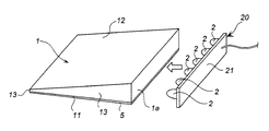
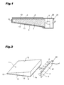
- FIG. 1 is a schematic cross sectional view illustrating a surface light source using an LED element.
- the surface light source comprises a light guide plate 1 , a point light source 2 formed by an LED element.
- a light source part 20 comprising a plurality of the point light sources 2 formed by white LED elements is arranged on an edge part of the light guide plate 1 .
- a light reflecting surface 11 is arranged on a side vertical to the point light source 2 of the light guide plate 1 , and a light emitting surface 12 is arranged on an opposite side to the light reflecting surface 11 .
- a white reflecting sheet 5 is arranged so as to face to the light reflecting surface 11 , and light transmitting through the light reflecting surface 11 is reflected on the white reflecting sheet 5 and returned to the light guide plate 1 .
- the light emitting surface 12 is arranged on a side opposing to the light reflecting surface 11 (a front surface side). Light from the point light sources 2 is reflected on the light reflecting surface 11 , three side surfaces 13 of the light guide plate 1 , and the reflecting sheet 5 , and most of the incident light is emitted from the light emitting surface 12 .
- a diffusing sheet 3 and a lens sheet 4 are arranged on an upper surface of the light emitting surface of the light guide plate 1 .
- a reflector 22 surrounds an LED substrate 21 mounting the LEDs as the plurality of point light sources 2 in the light source part 20 , and light from the point light sources 2 is guided to the light guide plate 1 .
- Color tone is one of performance indexes of a surface light source device. Generally it is evaluated by a xy value in a xy chromaticity diagram. Color tone is evaluated by color tone at a center part of the light emitting surface of the surface light source device, and color tone unevenness in comparing those of the center part and a peripheral part.
- One unit of a surface light source device using a cold cathode ray tube lamp includes one unit of the cold cathode ray tube lamp. Therefore, color tone unevenness on a light emitting surface is reduced and color tone difference between individual lamps is relatively small.
- a surface light source device using an LED element as a light source uses a plurality of the LED elements. Furthermore, color tone between the individual LED elements is different. Therefore, it has disadvantage in color tone and color tone unevenness as compared with the surface light source device using a cold cathode ray tube lamp.
- a white LED element In general, a white LED element is categorized into a plurality of grades by luminous intensity and color tone and is shipped with information of what grade of luminous intensity and color tone the LED element was given. However, it is difficult to specify and purchase LED elements of the desired grade. The purchaser can only confirm the properties of the purchased LEDs. In some case, although it is possible to specify the grade of LEDs to be purchased, it may have disadvantage in cost and delivery.
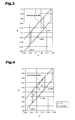
- FIG. 3 is one example of color tone grades of a white LED element.
- LED elements are categorized into three grades “a, b, c” in the xy chromaticity diagram. As compared with an LED in the “b” grade in center, the LED in the “a” grade is bluey white, the LED in the “c” grade is yellowish white. A manufacturer gives this color tone grade with regard to distributions of white LED elements on a xy chromaticity diagram. More specific classification other than the three-group classification or other gradation are made in other cases.
- LED elements in the “b” grade are preferred in viewpoint of center color tone and evenness of color tone.
- the device is only formed of only the “b” graded elements and the “a” and “c” graded elements are disused. Manufacture cost increases as a whole.
- This invention was made to solve these problems and provides a surface light source device capable of suppressing chromaticity difference even in using a point light source.
- a surface light source device equivalent to the one comprising only the white LED elements of the “b” grade is provided even when the white LED elements of the “a” and “c” grades are added to the “b” grade elements.
- a surface light source device comprises a light guide plate including a light incident surface and a light emitting surface, a light source part including a plurality of point light sources arranged on a light incident surface side of the light guide plate. Two of the point light sources of the light source part having chromaticity out of a center of an aimed chromaticity range in opposite hue directions are arranged adjacently.
- the light incident surface is provided on one side end surface of the light guide plate, and the light emitting surface is provided on a front surface positioned in vertical direction to the one side end surface of the light guide plate.
- a light reflecting member is provided on an opposite side of the light incident surface.
- the light reflecting member is provided with chromaticity correcting means corresponding to emitted light.
- the light source part is provided with not less than four point light sources, and two of the point light sources having chromaticity out of the center of the aimed chromaticity range in the opposite hue directions are arranged in an approximately center of a group of the plurality of the point light sources.
- the two of the point light sources have the chromaticity outermost from the center of the aimed chromaticity range in the opposite hue directions.
- the point light source comprises a white light emitting diode element.
- the point light sources of different hues are arranged adjacently in the surface light source device of this invention. Therefore, colors of the point light sources are mixed and color tone turns into a medium one. Thus, the surface light source device capable of suppressing color tone difference as a whole can be provided.
- the point light sources of different hues are arranged adjacently in the surface light source device of this invention, and colors of the point light sources are mixed and color tone turns into a medium one.
- the surface light source device capable of suppressing color tone difference as a whole can be provided, and the surface light source can satisfy an aimed chromaticity range.
- the surface light source device out of the aimed chromaticity range can be modified in one having the aimed chromaticity range by arranging chromaticity correcting means in connection with an optical propagating path of the light guide plate.
- An adjusting method of a surface light source device which light is incident from a light source arranged on a side of a light incident surface provided on a one side end surface of a light guide plate, is reflected on a reflecting member arranged in proximity to a rear surface opposite to a front surface of the light guide plate, and is emitted as a plane-shaped light from the front surface of the light guide plate comprises a process for providing measurement of chromaticity difference from an aimed chromaticity range of light which is emitted from the light source and further emitted from the light guide plate, and a process for selecting a colored reflecting member for correcting the emitted light to be in the aimed chromaticity range as a reflecting member arranged in proximity of the rear surface of the light guide plate.
- a chromaticity difference from the aimed chromaticity range is measured and a colored reflecting member for correcting emitted light to be in the aimed chromaticity range is arranged in proximity of the rear surface of the light guide plate on the basis of the measured chromaticity difference.
- the point light sources and the light source comprises a group of the point light sources including not less than four white light emitting diode elements, and two of the white light emitting diode elements having chromaticity outermost from a center of the aimed chromaticity range in opposite hue directions are arranged in an approximately center of the group of the point light sources.
- the chromaticity correcting means is a colored reflecting member provided on a rear surface opposite to the front surface of the light guide plate for emitting light.
- FIG. 1 is a cross sectional view illustrating a schematic structure of a surface light source device according to this invention
- FIG. 2 is a perspective view illustrating a schematic structure of the surface light source device according to this invention.
- FIG. 3 is a xy chromaticity diagram illustrating one example of color tone grade of a white LED element
- FIG. 4 is a xy chromaticity diagram illustrating color tone of the surface light source device using the white LED elements of the “b” grade;
- FIG. 5 is a xy chromaticity diagram illustrating color tone of the surface light source device using the white LED elements of the “a, b, c” grades;
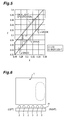
- FIG. 6 is a schematic plane view of a surface light source device which is a base of this invention.
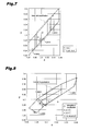
- FIG. 7 is a xy chromaticity diagram illustrating color tone of the surface light source device of this embodiment using the white LED elements of the “a, b, c”grades;
- FIG. 8 is a xy chromaticity diagram illustrating color tone of the surface light source device according to this embodiment using the white LED elements categorized approximately in the “a” grade.
- FIG. 2 is a perspective view illustrating a schematic structure of a surface light source device according to this invention.
- a diffusing sheet and a lens sheet 4 arranged on a light emitting surface side and a reflector for surrounding point light sources are omitted.
- This invention is applied to a surface light source device in FIG. 1, and is pertinent to the surface light source device with a plurality of the point light sources 2 arranged in parallel on a light incident surface side of the light guide plate 1 .
- the surface light source device comprises a light guide plate 1 , a light source part 20 provided with point light sources 2 formed of white LED elements, and any of controlling circuits (not shown).
- the controlling circuits includes a circuit for detecting a total quantity of light emitted from a light emitting surface 12 of the light guide plate 1 and adjusting and supplying power to the point light sources 2 so as to optimize quantity of the emitted light.
- the point light sources 2 formed by the white LED elements are arranged opposite to the light incident surface 1 a provided on an edge part of the light guide plate 1 .
- six white LED elements as the point light sources 2 are arranged on a substrate 21 .
- This white LED element may be structured by housing three LEDs of R, G, B so as to emit white light or may be structured by using a single color LED and converting emitted light from the LED into white light by the aid of phosphor material.
- the phosphor material may be YAG(yttrium aluminum garnet) based phosphor material for a GaN based blue LED.
- a reflecting sheet 5 serving as light reflecting material is arranged on a rear surface of one main surface on a side vertical to the point light sources 2 of the light guide plate 1 , and forms a light reflecting surface 11 together with the rear surface.
- the light reflecting surface 11 is formed to have a recessed part of a cone shape or is dot-printed so as to prevent light leakage and improve reflection efficiency.
- the light emitting surface 12 is provided on a side opposite to the light reflecting surface 11 of the light guide plate 1 . Light from each of the LEDs of the point light sources 2 is reflected to the light reflecting surface 11 including the reflecting sheet 5 and the three side surfaces of the light guide plate 1 , and most of the incident light is emitted as synthesized light of uniform directivity from the light emitting surface 12 .
- Material for the light guide plate 1 is selected from translucent material, generally acrylic or polycarbonate resin is used.
- the shape of the light guide plate 1 is a parallel flat plate and a cross sectional wedge-shaped flat plate, and the thickness is generally 1-5 mm.
- the LED can reduce the thickness of the device as compared with a cold cathode ray tube lamp.
- the other transparent materials include acrylic ester such as polymethyl methacrylate and polyacrylic acid methyl, methacrylate ester alone or its copolymers, polyester such as polyethylene terephthalate and polybutylene terephthalate, thermoplastic resin such as polycarbonate, polystyrene, and polymethylpentene, acrylate such as multifunctional urethane acrylate and polyester acrylate cross-linked by ultraviolet rays or electron beams, transparent resin such as unsaturated polyester, transparent glass, and transparent ceramics.
- acrylic ester such as polymethyl methacrylate and polyacrylic acid methyl
- polyester such as polyethylene terephthalate and polybutylene terephthalate
- thermoplastic resin such as polycarbonate, polystyrene, and polymethylpentene
- acrylate such as multifunctional urethane acrylate and polyester acrylate cross-linked by ultraviolet rays or electron beams
- transparent resin such as unsaturated polyester
- a diffusing sheet and a lens sheet are arranged on an upper surface of the light emitting surface 11 of the light guide plate 1 .
- the number of sheets may be one or two, and may be interposed in the reverse order.
- the LED substrate 21 mounted with the LED elements is fixed to an outer frame (not shown) positioned on an outer side of the light guide plate 1 with a screw or adhesive, and the point light sources 2 are arranged on a predetermined position of the light guide plate 1 .
- a liquid crystal display panel is arranged in proximity of the lens sheet.
- the surface light source device of the first embodiment is formed by using six white LED elements only of the “b” grade as the point light sources 2 .
- Color tone of the surface light source device is shown in FIG. 4 .
- “ ⁇ ” in the diagram indicates chromaticity of each of the six white LED elements, and “ ⁇ ” indicates chromaticity of the surface light source when the surface light surface device is formed by the six white LED elements.
- all of the white LED elements are classified in the “b” grade and the chromaticity on the surface light source satisfies the specification.
- the LED elements on the LED substrate 21 is arranged in an order of the grades b, a, b, b, c, b from a left side as shown in Table 1, and the surface light source device of the second embodiment is formed.
- FIG. 5 illustrates chromaticity of each of white LED elements and chromaticity of a surface light source of the surface light source device of a second embodiment.
- ⁇ indicates chromaticity of each of the six white LED elements
- ⁇ is chromaticity on the surface light source formed by the white LED elements.
- chromaticity of the surface light source in this structure satisfies the specification.
- a surface light source device in this embodiment is formed by preparing white LED elements of approximately equal chromaticity as those used in the second embodiment and changing arrangement order of the white LED elements on the LED substrate 21 .
- FIG. 7 illustrates chromaticity of each of the white LED elements and chromaticity of the surface light source of this embodiment.
- “ ⁇ ” indicates chromaticity of each of the six white LED elements
- “ ⁇ ” indicates chromaticity on the surface light source formed by the white LED elements.
- chromaticity on the surface light source in this structure satisfies specification required.
- Color tone unevenness observed in the second embodiment does not appear and a surface light source of good quality is provided.
- more incident light from the white LED elements of the “b” and “c” grades is incident to a right end part of the light emitting surface, and the emitting light has a mixed color of the “b” and “c” grades.
- LEDs of the “a” and “c” grades are arranged in proximity at a center part of the LED substrate 21 , and colors of these LEDs are mixed to be a middle color between “a” and “c” that is like the color of the “b” grade. Therefore, this embodiment can provide a surface light source device having less unevenness in chromaticity.
- the point light sources 2 of six white LED elements are used.
- the number of the point light sources is not limited to six.
- the two white LED elements which have chromaticity outermost from the center of the aimed chromaticity range in opposite hue directions are selected and arranged adjacently on the LED substrate 21 so that color tone unevenness is reduced.
- the two white LED elements which have chromaticity outermost from the center of the aimed chromaticity range in the opposite hue directions are selected and arranged adjacently in an approximately center of a group of the plurality of the point light sources 2 on the LED substrate 21 so that color tone unevenness is reduced.
- this invention can suppress color tone unevenness in using the point light sources and cost of the surface light source device.
- This invention also can provide a surface light source device having uniform color tone and a center chromaticity equivalent to those of a surface light source device comprising the white LED element of the “b” grade even when the device comprises white LED elements of the “a” and “c” grades together with the elements of the “b” grade. Therefore, white LED elements in a wide chromaticity range are available and cost for the surface light source device can be reduced.
- the surface light source device capable of reducing color tone unevenness and satisfying a chromaticity range is provided by adjusting arrangement of the plurality of the white LED elements.
- some of the surface light source devices may deviate from a specification of a chromaticity range. This is because that the dispersion of chromaticity of the white LED elements of a same grade is not uniform.
- chromaticity is adjusted to be within the specification by arranging chromaticity correcting means for emitted light in connection with an optical propagating path of the light guide plate in the surface light source device having chromaticity out of a range of the specification while using the white LED elements in a wide range of chromaticity.
- the point light sources of the white LED element of each of the grades are mounted on the LED substrate 21 in accordance with the above rule, and then the LED substrate 21 is mounted on the light guide plate 1 with a white reflecting sheet 5 arranged in advance as a reference chromaticity or an aimed chromaticity and all of the point light sources 2 light up to measure the chromaticity of the surface light source.
- Judgment on the basis of the measurement is conducted to judge whether the chromaticity of the surface light source is within the aimed chromaticity range.
- the surface light source judged as a non-defective unit continues to be on production line so that the surface light source device is assembled.
- the LED substrate 21 judged as defective is removed from the light guide plate 1 and a new light guide plate 1 having a colored reflecting sheet 5 for color tone difference on the basis of the color tone difference from the aimed chromaticity range is prepared and mounted. Relation between color tone difference and a plurality of the prepared colored reflecting sheets 5 is stored in a table so that selection of chromaticity for correcting the color tone difference is automatically performed on the basis of the color tone difference obtained from the measurement.
- the LED substrate out of specification can turn into a usable non-defective unit.
- the chromaticity correcting means is not necessarily provided on the reflecting sheet 5 as long as it is provided in relation to the optical propagating path of the light guide plate 1 . Thus, it may be provided between the point light source 2 and the light guide plate 1 . However, because the reflecting sheet 5 provided with a correcting function does not increase the number of components and the reflecting sheet 5 itself serves as a normal reflecting sheet 5 required in any of surface light source devices which does not need correction, the reflecting sheet 5 having the chromaticity correcting means may be preferred.
- FIG. 8 is a xy chromaticity diagram for explaining an adjusting method of chromaticity in another embodiment.
- chromaticity is adjusted without changing arrangement of the white LED elements of the LED substrate 21 .
- the grades (a, b, c) of the white LED elements do not have substantial effect to the chromaticity of the surface light source.
- the surface light source device of FIG. 8 comprises the six white LED elements (the number of elements is not restricted and the device may comprise a single element in this embodiment), and xy chromaticity of each of the elements is generally of the “a” grade as indicated with “ ⁇ ” in the diagram. It has been found from the measurement that the chromaticity of the surface light source is marked out of the aimed chromaticity range as plotted with a diamond (indicated as a conventional specification).
- the colored reflecting sheet 5 corresponding to the color tone difference is selected on the basis of the table prepared in accordance with the color tone difference as described above and is made to correspond to the aimed chromaticity range.
- a color temperature converting filter No. A1 (indicated as y(A1)) by Tokyo Butai Syowmei Co., Ltd. is used so that the color temperature is converted from 3400° k to 3200° k and the surface light source device having the aimed chromaticity range plotted with a symbol “x” is provided.
- This embodiment has been paid attention to the conventional reflecting sheet 5 and provides a function for correcting chromaticity to the reflecting sheet 5 .
- the LED substrate 21 out of the aimed range of chromaticity can become usable without adding a component.
- this adjusting method according to this invention can suppress color tone unevenness in using a point light source, and reduce cost for the surface light source device.
- a surface light source device equivalent to the one comprising only the white LED elements of the “b” grade is provided even when the white LED elements of the “a” and “c” grades are added to the “b” grade elements, the white LED elements of only the “a” grade or the “c” grade, or the white LED elements not strictly categorized by such the grades are used.
- the white LED elements in a wide range of chromaticity can be used to reduce cost for the surface light source device.
- the chromaticity difference from the aimed chromaticity range is measured.
- the colored reflecting member for correcting the emitted light to be within the aimed chromaticity range is arranged in proximity of a rear surface of the light guide plate on the basis of the measured chromaticity difference.
Abstract
Description
| TABLE 1 |
| Arrangement on the LED substrate (from a left side) |
| 1 | 2 | 3 | 4 | 5 | 6 | ||
| b | a | b | b | c | b | ||
| TABLE 2 |
| Arrangement on the LED substrate (from a left side) |
| 1 | 2 | 3 | 4 | 5 | 6 | ||
| b | b | c | a | b | b | ||
Claims (12)
Applications Claiming Priority (4)
| Application Number | Priority Date | Filing Date | Title |
|---|---|---|---|
| JP11-335376 | 1999-11-26 | ||
| JP33537699A JP2001155524A (en) | 1999-11-26 | 1999-11-26 | Surface light source device |
| JP36629499A JP3530442B2 (en) | 1999-12-24 | 1999-12-24 | Chromaticity adjustment method for surface light source device |
| JP11-366294 | 1999-12-24 |
Publications (1)
| Publication Number | Publication Date |
|---|---|
| US6508564B1 true US6508564B1 (en) | 2003-01-21 |
Family
ID=26575157
Family Applications (1)
| Application Number | Title | Priority Date | Filing Date |
|---|---|---|---|
| US09/717,144 Expired - Lifetime US6508564B1 (en) | 1999-11-26 | 2000-11-22 | Surface light source device and adjusting method of chromaticity thereof |
Country Status (3)
| Country | Link |
|---|---|
| US (1) | US6508564B1 (en) |
| KR (1) | KR100481098B1 (en) |
| TW (1) | TW500962B (en) |
Cited By (57)
| Publication number | Priority date | Publication date | Assignee | Title |
|---|---|---|---|---|
| US20040090191A1 (en) * | 1997-08-26 | 2004-05-13 | Color Kinetics, Incorporated | Multicolored led lighting method and apparatus |
| US20040090787A1 (en) * | 2002-08-28 | 2004-05-13 | Color Kinetics, Inc. | Methods and systems for illuminating environments |
| US20040105250A1 (en) * | 2002-11-29 | 2004-06-03 | Charles Leu | Light guide plate and backlight system using the same |
| US20040105261A1 (en) * | 1997-12-17 | 2004-06-03 | Color Kinetics, Incorporated | Methods and apparatus for generating and modulating illumination conditions |
| US20040109664A1 (en) * | 2002-07-26 | 2004-06-10 | Advanced Display Inc. | Planar light source device and liquid crystal display device using the same |
| US20040130912A1 (en) * | 2002-12-20 | 2004-07-08 | Citizen Electronics Co., Ltd. | Light guide plate and support unit for the same |
| US20040184258A1 (en) * | 2003-03-21 | 2004-09-23 | Chang-Chieh Sung | Surface lighting device with closed oblique reflector |
| US20040207822A1 (en) * | 2003-04-15 | 2004-10-21 | Samsung Electronics Co., Ltd. | Projection display |
| WO2004100613A1 (en) * | 2003-05-07 | 2004-11-18 | Koninklijke Philips Electronics N.V. | User interface for controlling light emitting diodes |
| US20050041424A1 (en) * | 1999-11-18 | 2005-02-24 | Color Kinetics, Inc. | Systems and methods for converting illumination |
| US20050040774A1 (en) * | 1999-11-18 | 2005-02-24 | Color Kinetics, Inc. | Methods and apparatus for generating and modulating white light illumination conditions |
| US20050047110A1 (en) * | 2003-08-29 | 2005-03-03 | Yin-Chun Huang | Illumination module of light emitting elements |
| EP1533851A2 (en) * | 2003-11-20 | 2005-05-25 | Sumitomo Electric Industries, Ltd. | Light-emitting diode and semiconductor light-emitting device |
| US20050151489A1 (en) * | 1997-08-26 | 2005-07-14 | Color Kinetics Incorporated | Marketplace illumination methods and apparatus |
| US20050157521A1 (en) * | 2004-01-20 | 2005-07-21 | Shih-Hsien Chen | Backlight assembly for liquid crystal display |
| US20050174804A1 (en) * | 2002-04-05 | 2005-08-11 | Phlox | Backlighting apparatus |
| US20050185113A1 (en) * | 2001-01-16 | 2005-08-25 | Visteon Global Technologies, Inc. | LED backlighting system |
| US20050207140A1 (en) * | 2004-03-16 | 2005-09-22 | Hadi Srass | Ceiling fan with light assembly |
| US20050285547A1 (en) * | 1997-08-26 | 2005-12-29 | Color Kinetics Incorporated | Light emitting diode based products |
| US20050286264A1 (en) * | 2004-06-29 | 2005-12-29 | Gi-Cherl Kim | Backlight for display device, light source for display device, and light emitting diode used therefor |
| US7001060B1 (en) | 1999-08-11 | 2006-02-21 | Semiconductor Energy Laboratory Co., Ltd. | Front light having a plurality of prism-shaped lenses |
| US20060114693A1 (en) * | 2004-12-01 | 2006-06-01 | Au Optronics Corporation | Light emitting diode backlight package |
| US20060215388A1 (en) * | 2005-03-22 | 2006-09-28 | Tetsuya Hamada | Surface illuminator and liquid crystal display having the same |
| US20060221641A1 (en) * | 2005-04-01 | 2006-10-05 | Samsung Electronics Co., Ltd. | Light emitting diode backlight and liquid crystal display having the same |
| US20070058396A1 (en) * | 2005-09-09 | 2007-03-15 | Innolux Display Corp. | Backlight module with light guide protrusion and liquid crystal display with same |
| US20070058392A1 (en) * | 2005-09-09 | 2007-03-15 | Citizen Electronics Co., Ltd. | Lighting device |
| US20070139959A1 (en) * | 2005-12-20 | 2007-06-21 | Chih-Rong Yang | Light source device |
| US20070223245A1 (en) * | 2006-03-24 | 2007-09-27 | Lg Electronics Inc. | Surface light source, backlight unit and liquid crystal display having the same |
| US20070274093A1 (en) * | 2006-05-25 | 2007-11-29 | Honeywell International, Inc. | LED backlight system for LCD displays |
| US20070297189A1 (en) * | 2004-06-02 | 2007-12-27 | Wu Rong Y | Linear light source for enhancing uniformity of beaming light within the beaming light's effective focal range |
| US20080068821A1 (en) * | 2006-09-14 | 2008-03-20 | Industrial Technology Research Institute | Light emitting apparatus and image monitor |
| US20080089096A1 (en) * | 2006-10-16 | 2008-04-17 | Innocom Technology (Shenzhen) Co., Ltd. | Backlight module having colored reflective structure and liquid crystal display using same |
| US20080144324A1 (en) * | 2005-03-16 | 2008-06-19 | Hisashi Tahara | Light Guiding Plate Made of Transparent Resin, Surface-Emitting Light Source Apparatus and Process For Manufacturing Light Guiding Plate |
| US20080151141A1 (en) * | 2005-12-23 | 2008-06-26 | Innolux Display Corp. | Backlight module and liquid crystal display using same |
| US20080285268A1 (en) * | 2004-11-09 | 2008-11-20 | Takashi Oku | Backlight Device |
| US20080310152A1 (en) * | 2004-06-29 | 2008-12-18 | Koninklijke Philips Electronics, N.V. | Led Lighting |
| WO2009037109A1 (en) * | 2007-09-20 | 2009-03-26 | Industrias Ramon Soler, S. A. | Led surface lighting device using edge-illuminated light-guide plate |
| US20090129117A1 (en) * | 2007-10-23 | 2009-05-21 | Lg Display Co., Ltd. | Backlight assembly |
| US20090236620A1 (en) * | 2008-03-14 | 2009-09-24 | Dong Wook Park | Light emitting apparatus and display apparatus having the same |
| EP2120088A1 (en) * | 2008-05-13 | 2009-11-18 | LG Display Co., Ltd. | Backlight Unit Including Light Emitting Diodes and Liquid Crystal Display Device Including the Same |
| US7646143B2 (en) * | 2000-04-21 | 2010-01-12 | Semiconductor Energy Laboratory Co., Ltd. | Self-light emitting device and electrical appliance using the same |
| US20100128199A1 (en) * | 2008-11-21 | 2010-05-27 | Kyung Jun Kim | Light emitting apparatus and display apparatus using the same |
| EP2208109A1 (en) * | 2007-10-10 | 2010-07-21 | Apple Inc. | Led backlight for display systems |
| EP2219054A1 (en) * | 2009-02-17 | 2010-08-18 | LG Innotek Co., Ltd. | Light emitting module and display device having the same |
| US20100327769A1 (en) * | 2009-06-26 | 2010-12-30 | Young Lighting Technology Corporation | Light plate |
| US20110019258A1 (en) * | 2008-02-13 | 2011-01-27 | Nokia Corporation | Display device and a method for illuminating a light modulator array of a display device |
| EP2426399A1 (en) * | 2009-06-15 | 2012-03-07 | Sharp Kabushiki Kaisha | Illuminating device, display device, and television receiver |
| US20130021822A1 (en) * | 2010-01-20 | 2013-01-24 | Zumtobel Lighting Gmbh | Optical Waveguide Plate Comprising Phosphorus-Containing Structure Elements |
| US20130107515A1 (en) * | 2008-03-28 | 2013-05-02 | Cree, Inc. | Apparatus and Methods for Combining Light Emitters |
| US20140119053A1 (en) * | 2012-10-30 | 2014-05-01 | Beijing Boe Display Technology Co., Ltd. | Backlight module and display device |
| US20140240612A1 (en) * | 2011-10-31 | 2014-08-28 | Sharp Kabushiki Kaisha | Display device, television device, and method of manufacturing display device |
| US20150029439A1 (en) * | 2013-07-29 | 2015-01-29 | Samsung Display Co., Ltd. | Backlight assembly and liquid crystal display having the same |
| US9115852B2 (en) | 2008-12-19 | 2015-08-25 | Osram Opto Semiconductors Gmbh | Method for producing a plurality of LED illumination devices and a plurality of LED chipsets for illumination devices, and LED illumination device |
| CN105759470A (en) * | 2016-04-05 | 2016-07-13 | 中航华东光电有限公司 | Side-backlight independent disassembly-assembly structure |
| US20160327223A1 (en) * | 2015-05-08 | 2016-11-10 | Osram Gmbh | Lighting device and corresponding method |
| US20170261675A1 (en) * | 2014-05-16 | 2017-09-14 | Corning Incorporated | Edge lighted backlight unit for liquid crystal display device |
| US10136499B2 (en) | 2015-02-02 | 2018-11-20 | Lg Innotek Co., Ltd. | Light-emitting module and lighting apparatus provided with same |
Families Citing this family (2)
| Publication number | Priority date | Publication date | Assignee | Title |
|---|---|---|---|---|
| KR100829015B1 (en) * | 2006-08-22 | 2008-05-14 | 엘지전자 주식회사 | Surface light source, back light unit and liquid crystal display having the same |
| US20150019168A1 (en) * | 2012-01-31 | 2015-01-15 | Sharp Kabushiki Kaisha | Led classification method, led classification device, and recording medium |
Citations (11)
| Publication number | Priority date | Publication date | Assignee | Title |
|---|---|---|---|---|
| JPH07140567A (en) | 1993-09-21 | 1995-06-02 | Fuji Photo Film Co Ltd | Image recorder |
| JPH08146228A (en) | 1994-11-24 | 1996-06-07 | Kyocera Corp | Liquid crystal display device |
| JPH09292614A (en) | 1996-04-26 | 1997-11-11 | Hitachi Ltd | Liquid crystal display device |
| JPH1152327A (en) | 1997-07-30 | 1999-02-26 | Fujitsu Ltd | Liquid crystal display device and its display control method |
| JPH11223805A (en) | 1998-02-09 | 1999-08-17 | Sony Corp | Lighting system |
| US5998925A (en) * | 1996-07-29 | 1999-12-07 | Nichia Kagaku Kogyo Kabushiki Kaisha | Light emitting device having a nitride compound semiconductor and a phosphor containing a garnet fluorescent material |
| US6036328A (en) * | 1995-05-23 | 2000-03-14 | Sharp Kabushiki Kaisha | Plane-shaped lighting device and a display using such a device |
| JP2000285718A (en) * | 1999-03-29 | 2000-10-13 | Rohm Co Ltd | Surface light source |
| JP2000331517A (en) * | 1999-05-18 | 2000-11-30 | Stanley Electric Co Ltd | Visually recognizable auxiliary tool |
| US6313816B1 (en) * | 1998-09-16 | 2001-11-06 | Sony Corporation | Display apparatus |
| KR20020064124A (en) | 2001-02-01 | 2002-08-07 | 주식회사 티비알 | method for attenuation generated noise in radio antenna driver device |
Family Cites Families (5)
| Publication number | Priority date | Publication date | Assignee | Title |
|---|---|---|---|---|
| KR910009259Y1 (en) * | 1988-07-26 | 1991-11-28 | 서통디스프레이테크 주식회사 | Multi-color display device using negative type liquid crystal cell |
| JP3533475B2 (en) * | 1994-04-05 | 2004-05-31 | カシオ計算機株式会社 | Liquid crystal display |
| KR970028700A (en) * | 1995-11-10 | 1997-06-24 | 윤종용 | Backlight manufacturing method of liquid crystal display |
| JP3538746B2 (en) * | 1997-03-07 | 2004-06-14 | 株式会社エンプラス | Sidelight type surface light source device |
| JPH11295731A (en) * | 1998-04-09 | 1999-10-29 | Hitachi Ltd | Liquid crystal display device |
-
2000
- 2000-11-10 TW TW089123761A patent/TW500962B/en not_active IP Right Cessation
- 2000-11-22 US US09/717,144 patent/US6508564B1/en not_active Expired - Lifetime
- 2000-11-25 KR KR10-2000-0070675A patent/KR100481098B1/en active IP Right Grant
Patent Citations (11)
| Publication number | Priority date | Publication date | Assignee | Title |
|---|---|---|---|---|
| JPH07140567A (en) | 1993-09-21 | 1995-06-02 | Fuji Photo Film Co Ltd | Image recorder |
| JPH08146228A (en) | 1994-11-24 | 1996-06-07 | Kyocera Corp | Liquid crystal display device |
| US6036328A (en) * | 1995-05-23 | 2000-03-14 | Sharp Kabushiki Kaisha | Plane-shaped lighting device and a display using such a device |
| JPH09292614A (en) | 1996-04-26 | 1997-11-11 | Hitachi Ltd | Liquid crystal display device |
| US5998925A (en) * | 1996-07-29 | 1999-12-07 | Nichia Kagaku Kogyo Kabushiki Kaisha | Light emitting device having a nitride compound semiconductor and a phosphor containing a garnet fluorescent material |
| JPH1152327A (en) | 1997-07-30 | 1999-02-26 | Fujitsu Ltd | Liquid crystal display device and its display control method |
| JPH11223805A (en) | 1998-02-09 | 1999-08-17 | Sony Corp | Lighting system |
| US6313816B1 (en) * | 1998-09-16 | 2001-11-06 | Sony Corporation | Display apparatus |
| JP2000285718A (en) * | 1999-03-29 | 2000-10-13 | Rohm Co Ltd | Surface light source |
| JP2000331517A (en) * | 1999-05-18 | 2000-11-30 | Stanley Electric Co Ltd | Visually recognizable auxiliary tool |
| KR20020064124A (en) | 2001-02-01 | 2002-08-07 | 주식회사 티비알 | method for attenuation generated noise in radio antenna driver device |
Cited By (120)
| Publication number | Priority date | Publication date | Assignee | Title |
|---|---|---|---|---|
| US20050151489A1 (en) * | 1997-08-26 | 2005-07-14 | Color Kinetics Incorporated | Marketplace illumination methods and apparatus |
| US20080012506A1 (en) * | 1997-08-26 | 2008-01-17 | Color Kinetics Incorporated | Multicolored led lighting method and apparatus |
| US20040090191A1 (en) * | 1997-08-26 | 2004-05-13 | Color Kinetics, Incorporated | Multicolored led lighting method and apparatus |
| US7161313B2 (en) | 1997-08-26 | 2007-01-09 | Color Kinetics Incorporated | Light emitting diode based products |
| US20040178751A1 (en) * | 1997-08-26 | 2004-09-16 | Color Kinetics, Incorporated | Multicolored lighting method and apparatus |
| US20050285547A1 (en) * | 1997-08-26 | 2005-12-29 | Color Kinetics Incorporated | Light emitting diode based products |
| US20040105261A1 (en) * | 1997-12-17 | 2004-06-03 | Color Kinetics, Incorporated | Methods and apparatus for generating and modulating illumination conditions |
| US20060152172A9 (en) * | 1997-12-17 | 2006-07-13 | Color Kinetics, Inc. | Methods and apparatus for generating and modulating white light illumination conditions |
| US20060109649A1 (en) * | 1997-12-17 | 2006-05-25 | Color Kinetics Incorporated | Methods and apparatus for controlling a color temperature of lighting conditions |
| US20060012987A9 (en) * | 1997-12-17 | 2006-01-19 | Color Kinetics, Incorporated | Methods and apparatus for generating and modulating illumination conditions |
| US7001060B1 (en) | 1999-08-11 | 2006-02-21 | Semiconductor Energy Laboratory Co., Ltd. | Front light having a plurality of prism-shaped lenses |
| US7959320B2 (en) | 1999-11-18 | 2011-06-14 | Philips Solid-State Lighting Solutions, Inc. | Methods and apparatus for generating and modulating white light illumination conditions |
| US20050030744A1 (en) * | 1999-11-18 | 2005-02-10 | Color Kinetics, Incorporated | Methods and apparatus for generating and modulating illumination conditions |
| US8142051B2 (en) | 1999-11-18 | 2012-03-27 | Philips Solid-State Lighting Solutions, Inc. | Systems and methods for converting illumination |
| US7132785B2 (en) | 1999-11-18 | 2006-11-07 | Color Kinetics Incorporated | Illumination system housing multiple LEDs and provided with corresponding conversion material |
| US20070115658A1 (en) * | 1999-11-18 | 2007-05-24 | Color Kinetics Incorporated | Methods and apparatus for generating and modulating white light illumination conditions |
| US20050041424A1 (en) * | 1999-11-18 | 2005-02-24 | Color Kinetics, Inc. | Systems and methods for converting illumination |
| US20070115665A1 (en) * | 1999-11-18 | 2007-05-24 | Color Kinetics Incorporated | Methods and apparatus for generating and modulating white light illumination conditions |
| US20060285325A1 (en) * | 1999-11-18 | 2006-12-21 | Color Kinetics Incorporated | Conventionally-shaped light bulbs employing white leds |
| US20050040774A1 (en) * | 1999-11-18 | 2005-02-24 | Color Kinetics, Inc. | Methods and apparatus for generating and modulating white light illumination conditions |
| US8686624B2 (en) | 2000-04-21 | 2014-04-01 | Semiconductor Energy Laboratory Co., Ltd. | Self-light emitting device and electrical appliance using the same |
| US20100171424A1 (en) * | 2000-04-21 | 2010-07-08 | Semiconductor Energy Laboratory Co., Ltd. | Self-Light Emitting Device and Electrical Appliance Using the Same |
| US9923171B2 (en) | 2000-04-21 | 2018-03-20 | Semiconductor Energy Laboratory Co., Ltd. | Self-light emitting device and electrical appliance using the same |
| US7646143B2 (en) * | 2000-04-21 | 2010-01-12 | Semiconductor Energy Laboratory Co., Ltd. | Self-light emitting device and electrical appliance using the same |
| US7193248B2 (en) * | 2001-01-16 | 2007-03-20 | Visteon Global Technologies, Inc. | LED backlighting system |
| US20050185113A1 (en) * | 2001-01-16 | 2005-08-25 | Visteon Global Technologies, Inc. | LED backlighting system |
| US20050174804A1 (en) * | 2002-04-05 | 2005-08-11 | Phlox | Backlighting apparatus |
| US7125154B2 (en) * | 2002-04-05 | 2006-10-24 | Phlox | Backlighting apparatus |
| US6976779B2 (en) * | 2002-07-26 | 2005-12-20 | Advanced Display Inc. | Planar light source device and liquid crystal display device using the same |
| US20040109664A1 (en) * | 2002-07-26 | 2004-06-10 | Advanced Display Inc. | Planar light source device and liquid crystal display device using the same |
| US7204622B2 (en) * | 2002-08-28 | 2007-04-17 | Color Kinetics Incorporated | Methods and systems for illuminating environments |
| US20040090787A1 (en) * | 2002-08-28 | 2004-05-13 | Color Kinetics, Inc. | Methods and systems for illuminating environments |
| US20040105250A1 (en) * | 2002-11-29 | 2004-06-03 | Charles Leu | Light guide plate and backlight system using the same |
| US6883925B2 (en) * | 2002-11-29 | 2005-04-26 | Hon Hai Precision Ind. Co., Ltd | Light guide plate and backlight system using the same |
| US7188989B2 (en) * | 2002-12-20 | 2007-03-13 | Citizen Electronics Co., Ltd. | Light guide plate and support unit for the same |
| US20040130912A1 (en) * | 2002-12-20 | 2004-07-08 | Citizen Electronics Co., Ltd. | Light guide plate and support unit for the same |
| US20040184258A1 (en) * | 2003-03-21 | 2004-09-23 | Chang-Chieh Sung | Surface lighting device with closed oblique reflector |
| US7066601B2 (en) * | 2003-04-15 | 2006-06-27 | Samsung Electronics Co., Ltd. | Projection display having an illumination module and an optical modulator |
| US20040207822A1 (en) * | 2003-04-15 | 2004-10-21 | Samsung Electronics Co., Ltd. | Projection display |
| WO2004100613A1 (en) * | 2003-05-07 | 2004-11-18 | Koninklijke Philips Electronics N.V. | User interface for controlling light emitting diodes |
| US20060290710A1 (en) * | 2003-05-07 | 2006-12-28 | Koninklijke Philips Electronics N.V. | User interface for controlling light emitting diodes |
| US7358961B2 (en) | 2003-05-07 | 2008-04-15 | Koninklijke Philips Electronics N.V. | User interface for controlling light emitting diodes |
| US20060146538A1 (en) * | 2003-08-29 | 2006-07-06 | Transpacific Ip, Ltd. | Illumination module of light emitting elements |
| US7108385B2 (en) * | 2003-08-29 | 2006-09-19 | Yin-Chun Huang | Illumination module of light emitting elements |
| US7374326B2 (en) | 2003-08-29 | 2008-05-20 | Transpacific Ip, Ltd. | Illumination module of light emitting elements |
| US20050047110A1 (en) * | 2003-08-29 | 2005-03-03 | Yin-Chun Huang | Illumination module of light emitting elements |
| EP1533851A2 (en) * | 2003-11-20 | 2005-05-25 | Sumitomo Electric Industries, Ltd. | Light-emitting diode and semiconductor light-emitting device |
| EP1533851A3 (en) * | 2003-11-20 | 2010-05-26 | Sumitomo Electric Industries, Ltd. | Light-emitting diode and semiconductor light-emitting device |
| US20050157521A1 (en) * | 2004-01-20 | 2005-07-21 | Shih-Hsien Chen | Backlight assembly for liquid crystal display |
| US20050207140A1 (en) * | 2004-03-16 | 2005-09-22 | Hadi Srass | Ceiling fan with light assembly |
| US7036949B2 (en) * | 2004-03-16 | 2006-05-02 | Hunter Fan Company | Ceiling fan with light assembly |
| US20070297189A1 (en) * | 2004-06-02 | 2007-12-27 | Wu Rong Y | Linear light source for enhancing uniformity of beaming light within the beaming light's effective focal range |
| US20050286264A1 (en) * | 2004-06-29 | 2005-12-29 | Gi-Cherl Kim | Backlight for display device, light source for display device, and light emitting diode used therefor |
| US20080310152A1 (en) * | 2004-06-29 | 2008-12-18 | Koninklijke Philips Electronics, N.V. | Led Lighting |
| US7293907B2 (en) | 2004-06-29 | 2007-11-13 | Samsung Electronics Co., Ltd. | Backlight for display device, light source for display device, and light emitting diode used therefor |
| US7946723B2 (en) * | 2004-11-09 | 2011-05-24 | Sony Corporation | Backlight device |
| US20080285268A1 (en) * | 2004-11-09 | 2008-11-20 | Takashi Oku | Backlight Device |
| CN100367095C (en) * | 2004-12-01 | 2008-02-06 | 友达光电股份有限公司 | Back light module and its light emitting device |
| US7168842B2 (en) * | 2004-12-01 | 2007-01-30 | Au Optronics Corporation | Light emitting diode backlight package |
| US20060114693A1 (en) * | 2004-12-01 | 2006-06-01 | Au Optronics Corporation | Light emitting diode backlight package |
| US20080144324A1 (en) * | 2005-03-16 | 2008-06-19 | Hisashi Tahara | Light Guiding Plate Made of Transparent Resin, Surface-Emitting Light Source Apparatus and Process For Manufacturing Light Guiding Plate |
| US7616858B2 (en) | 2005-03-16 | 2009-11-10 | Mitsubishi Engineering-Plastics Corporation | Light guiding plate made of transparent resin, surface-emitting light source apparatus and process for manufacturing light guiding plate |
| US20060215388A1 (en) * | 2005-03-22 | 2006-09-28 | Tetsuya Hamada | Surface illuminator and liquid crystal display having the same |
| US7360941B2 (en) * | 2005-04-01 | 2008-04-22 | Samsung Electronics Co., Ltd. | Light emitting diode backlight and liquid crystal display having the same |
| US20060221641A1 (en) * | 2005-04-01 | 2006-10-05 | Samsung Electronics Co., Ltd. | Light emitting diode backlight and liquid crystal display having the same |
| US7401965B2 (en) | 2005-09-09 | 2008-07-22 | Innocom Technology (Shenzhen) Co., Ltd. | Backlight module with light guide protrusion and liquid crystal display with same |
| US7488103B2 (en) * | 2005-09-09 | 2009-02-10 | Citizen Electronics Co., Ltd. | Lighting device with light guide plate illuminated by LED |
| US20070058396A1 (en) * | 2005-09-09 | 2007-03-15 | Innolux Display Corp. | Backlight module with light guide protrusion and liquid crystal display with same |
| US20070058392A1 (en) * | 2005-09-09 | 2007-03-15 | Citizen Electronics Co., Ltd. | Lighting device |
| US7290914B2 (en) * | 2005-12-20 | 2007-11-06 | Giga-Byte Technology Co., Ltd. | Light source device |
| US20070139959A1 (en) * | 2005-12-20 | 2007-06-21 | Chih-Rong Yang | Light source device |
| US7445368B2 (en) * | 2005-12-23 | 2008-11-04 | Innocom Technology (Shenzhen) Co., Ltd. | Backlight module and liquid crystal display using same |
| US20080151141A1 (en) * | 2005-12-23 | 2008-06-26 | Innolux Display Corp. | Backlight module and liquid crystal display using same |
| US20070223245A1 (en) * | 2006-03-24 | 2007-09-27 | Lg Electronics Inc. | Surface light source, backlight unit and liquid crystal display having the same |
| US20070274093A1 (en) * | 2006-05-25 | 2007-11-29 | Honeywell International, Inc. | LED backlight system for LCD displays |
| US20080068821A1 (en) * | 2006-09-14 | 2008-03-20 | Industrial Technology Research Institute | Light emitting apparatus and image monitor |
| US7857485B2 (en) * | 2006-09-14 | 2010-12-28 | Industrial Technology Research Institute | Phosphor-based LED apparatus with UV reflector |
| US20080089096A1 (en) * | 2006-10-16 | 2008-04-17 | Innocom Technology (Shenzhen) Co., Ltd. | Backlight module having colored reflective structure and liquid crystal display using same |
| US7527418B2 (en) * | 2006-10-16 | 2009-05-05 | Innocom Technology (Shenzhen) Co., Ltd. | Backlight module having colored reflective structure and liquid crystal display using same |
| WO2009037109A1 (en) * | 2007-09-20 | 2009-03-26 | Industrias Ramon Soler, S. A. | Led surface lighting device using edge-illuminated light-guide plate |
| ES2341408A1 (en) * | 2007-09-28 | 2010-06-18 | Industrias Ramon Soler, S.A. | Led surface lighting device using edge-illuminated light-guide plate |
| EP2208109A1 (en) * | 2007-10-10 | 2010-07-21 | Apple Inc. | Led backlight for display systems |
| US8033707B2 (en) * | 2007-10-23 | 2011-10-11 | Lg Display Co., Ltd. | LED backlight assembly having lower brightness LEDs at ends |
| US20090129117A1 (en) * | 2007-10-23 | 2009-05-21 | Lg Display Co., Ltd. | Backlight assembly |
| US20110019258A1 (en) * | 2008-02-13 | 2011-01-27 | Nokia Corporation | Display device and a method for illuminating a light modulator array of a display device |
| US8331006B2 (en) | 2008-02-13 | 2012-12-11 | Nokia Corporation | Display device and a method for illuminating a light modulator array of a display device |
| US20110103089A1 (en) * | 2008-03-14 | 2011-05-05 | Dong Wook Park | Light emitting apparatus and display apparatus having the same |
| US8278670B2 (en) | 2008-03-14 | 2012-10-02 | Lg Innotek Co., Ltd. | Light emitting apparatus and display apparatus having the same |
| EP2237326A4 (en) * | 2008-03-14 | 2011-04-13 | Lg Innotek Co Ltd | Light-emitting device and display device including the same |
| US20090236620A1 (en) * | 2008-03-14 | 2009-09-24 | Dong Wook Park | Light emitting apparatus and display apparatus having the same |
| EP2237326A2 (en) * | 2008-03-14 | 2010-10-06 | LG Innotek Co., Ltd. | Light-emitting device and display device including the same |
| US8513871B2 (en) * | 2008-03-28 | 2013-08-20 | Cree, Inc. | Apparatus and methods for combining light emitters |
| US20130107515A1 (en) * | 2008-03-28 | 2013-05-02 | Cree, Inc. | Apparatus and Methods for Combining Light Emitters |
| EP2120088A1 (en) * | 2008-05-13 | 2009-11-18 | LG Display Co., Ltd. | Backlight Unit Including Light Emitting Diodes and Liquid Crystal Display Device Including the Same |
| US20090284682A1 (en) * | 2008-05-13 | 2009-11-19 | Koo-Hwa Lee | Backlight unit including light emitting diodes and liquid crystal display device including the same |
| US8339541B2 (en) | 2008-05-13 | 2012-12-25 | Lg Display Co., Ltd. | Backlight unit including light emitting diodes and liquid crystal display device including the same |
| CN102007612A (en) * | 2008-11-21 | 2011-04-06 | Lg伊诺特有限公司 | Light emitting apparatus and display apparatus using the same |
| US8913213B2 (en) | 2008-11-21 | 2014-12-16 | Lg Innotek Co., Ltd. | Light emitting apparatus and display apparatus using the same |
| US20100128199A1 (en) * | 2008-11-21 | 2010-05-27 | Kyung Jun Kim | Light emitting apparatus and display apparatus using the same |
| CN102007612B (en) * | 2008-11-21 | 2014-05-14 | Lg伊诺特有限公司 | Light emitting apparatus and display apparatus using same |
| US9115852B2 (en) | 2008-12-19 | 2015-08-25 | Osram Opto Semiconductors Gmbh | Method for producing a plurality of LED illumination devices and a plurality of LED chipsets for illumination devices, and LED illumination device |
| US20100208491A1 (en) * | 2009-02-17 | 2010-08-19 | Kyung Ho Shin | Light emitting module and display device having the same |
| EP2219054A1 (en) * | 2009-02-17 | 2010-08-18 | LG Innotek Co., Ltd. | Light emitting module and display device having the same |
| US8944667B2 (en) | 2009-02-17 | 2015-02-03 | Lg Innotek Co., Ltd. | Light emitting module and display device having the same |
| US8976316B2 (en) | 2009-06-15 | 2015-03-10 | Sharp Kabushiki Kaisha | Lighting device, display device and television receiver |
| EP2426399A4 (en) * | 2009-06-15 | 2013-05-22 | Sharp Kk | Illuminating device, display device, and television receiver |
| EP2426399A1 (en) * | 2009-06-15 | 2012-03-07 | Sharp Kabushiki Kaisha | Illuminating device, display device, and television receiver |
| US8485711B2 (en) * | 2009-06-26 | 2013-07-16 | Young Lighting Technology Inc. | Light plate |
| US20100327769A1 (en) * | 2009-06-26 | 2010-12-30 | Young Lighting Technology Corporation | Light plate |
| US20130021822A1 (en) * | 2010-01-20 | 2013-01-24 | Zumtobel Lighting Gmbh | Optical Waveguide Plate Comprising Phosphorus-Containing Structure Elements |
| US20140240612A1 (en) * | 2011-10-31 | 2014-08-28 | Sharp Kabushiki Kaisha | Display device, television device, and method of manufacturing display device |
| US9482808B2 (en) * | 2012-10-30 | 2016-11-01 | Boe Technology Group Co., Ltd. | Display device with backlight module having white and monochromatic LEDs |
| US20140119053A1 (en) * | 2012-10-30 | 2014-05-01 | Beijing Boe Display Technology Co., Ltd. | Backlight module and display device |
| US20150029439A1 (en) * | 2013-07-29 | 2015-01-29 | Samsung Display Co., Ltd. | Backlight assembly and liquid crystal display having the same |
| US20170261675A1 (en) * | 2014-05-16 | 2017-09-14 | Corning Incorporated | Edge lighted backlight unit for liquid crystal display device |
| US10018765B2 (en) * | 2014-05-16 | 2018-07-10 | Corning Incorporated | Edge lighted backlight unit for liquid crystal display device |
| US10136499B2 (en) | 2015-02-02 | 2018-11-20 | Lg Innotek Co., Ltd. | Light-emitting module and lighting apparatus provided with same |
| US20160327223A1 (en) * | 2015-05-08 | 2016-11-10 | Osram Gmbh | Lighting device and corresponding method |
| US10088116B2 (en) * | 2015-05-08 | 2018-10-02 | Osram Gmbh | Lighting device with plurality of strips bendable relative to each other and corresponding method |
| CN105759470A (en) * | 2016-04-05 | 2016-07-13 | 中航华东光电有限公司 | Side-backlight independent disassembly-assembly structure |
Also Published As
| Publication number | Publication date |
|---|---|
| KR20010051962A (en) | 2001-06-25 |
| KR100481098B1 (en) | 2005-04-07 |
| TW500962B (en) | 2002-09-01 |
Similar Documents
| Publication | Publication Date | Title |
|---|---|---|
| US6508564B1 (en) | Surface light source device and adjusting method of chromaticity thereof | |
| KR100714209B1 (en) | Surface light source device and liquid crystal display device using it | |
| US7039286B2 (en) | Light guide module having uniform light diffusion arrangement and method for making the same | |
| EP1684111B1 (en) | Surface light emitting apparatus | |
| US7406228B2 (en) | Backlight module structure for LED chip holder | |
| CN102478188B (en) | The display device of back light unit and use back light unit | |
| KR100619069B1 (en) | Multi-chip light emitting diode unit, backlight unit and liquid crystal display employing the same | |
| US7922368B2 (en) | Light module and flat light unit in a liquid crystal display device | |
| US7859614B2 (en) | Light emitting diode package having dual lens structure and backlight for liquid crystal display device implementing the same | |
| TWI494655B (en) | Hollow backlight device with structured films and display with the same | |
| KR100750130B1 (en) | Light emitting assembly, backlight unit and display | |
| CN110959129A (en) | Lighting device | |
| JP2006148036A (en) | Light emitting source and light emitting source array | |
| JP2010528432A (en) | White light backlight using color LED light source efficiently and similar products | |
| KR101948141B1 (en) | backlight unit and illumination system using the same | |
| US9016923B2 (en) | Lighting device, display device, and television receiver | |
| US20040100788A1 (en) | Light module for LCD panel | |
| JP2002109936A (en) | Flat light source device and display device | |
| JP3530442B2 (en) | Chromaticity adjustment method for surface light source device | |
| US20060203484A1 (en) | Light emitting diode, light emitting diode module, and related backlight system | |
| WO2009047891A9 (en) | Planar light source element array and image display device | |
| US6871973B2 (en) | Light module for LCD panel | |
| US7463315B2 (en) | Light coupling structure on light guide plate in a backlight module | |
| US20060209568A1 (en) | Direct type backlight module and related diffusion board | |
| JP2007184493A (en) | Light source device and display device |
Legal Events
| Date | Code | Title | Description |
|---|---|---|---|
| AS | Assignment |
Owner name: SANYO ELECTRIC CO., LTD., JAPAN Free format text: ASSIGNMENT OF ASSIGNORS INTEREST;ASSIGNORS:KUWABARA, SATOSHI;YAMASHITA, HIROSHI;YAMAMURA, TORU;AND OTHERS;REEL/FRAME:011304/0690 Effective date: 20001117 |
|
| FEPP | Fee payment procedure |
Free format text: PAYOR NUMBER ASSIGNED (ORIGINAL EVENT CODE: ASPN); ENTITY STATUS OF PATENT OWNER: LARGE ENTITY |
|
| STCF | Information on status: patent grant |
Free format text: PATENTED CASE |
|
| FPAY | Fee payment |
Year of fee payment: 4 |
|
| FEPP | Fee payment procedure |
Free format text: PAYER NUMBER DE-ASSIGNED (ORIGINAL EVENT CODE: RMPN); ENTITY STATUS OF PATENT OWNER: LARGE ENTITY Free format text: PAYOR NUMBER ASSIGNED (ORIGINAL EVENT CODE: ASPN); ENTITY STATUS OF PATENT OWNER: LARGE ENTITY |
|
| AS | Assignment |
Owner name: FOLTORA SERVICE LIMITED LIABILITY COMPANY, DELAWAR Free format text: ASSIGNMENT OF ASSIGNORS INTEREST;ASSIGNOR:SANYO ELECTRIC CO., LTD.;REEL/FRAME:023245/0550 Effective date: 20090706 |
|
| FPAY | Fee payment |
Year of fee payment: 8 |
|
| FEPP | Fee payment procedure |
Free format text: PAYER NUMBER DE-ASSIGNED (ORIGINAL EVENT CODE: RMPN); ENTITY STATUS OF PATENT OWNER: LARGE ENTITY Free format text: PAYOR NUMBER ASSIGNED (ORIGINAL EVENT CODE: ASPN); ENTITY STATUS OF PATENT OWNER: LARGE ENTITY |
|
| FPAY | Fee payment |
Year of fee payment: 12 |
|
| AS | Assignment |
Owner name: CALLAHAN CELLULAR L.L.C., DELAWARE Free format text: MERGER;ASSIGNOR:FOLTORA SERVICE LIMITED LIABILITY COMPANY;REEL/FRAME:037529/0938 Effective date: 20150826 |