US6515652B2 - Tactile pointing stick - Google Patents
Tactile pointing stick Download PDFInfo
- Publication number
- US6515652B2 US6515652B2 US09/793,461 US79346101A US6515652B2 US 6515652 B2 US6515652 B2 US 6515652B2 US 79346101 A US79346101 A US 79346101A US 6515652 B2 US6515652 B2 US 6515652B2
- Authority
- US
- United States
- Prior art keywords
- cap
- pointing stick
- post
- tactile
- disposed
- Prior art date
- Legal status (The legal status is an assumption and is not a legal conclusion. Google has not performed a legal analysis and makes no representation as to the accuracy of the status listed.)
- Expired - Fee Related, expires
Links
Images


Classifications
-
- G—PHYSICS
- G05—CONTROLLING; REGULATING
- G05G—CONTROL DEVICES OR SYSTEMS INSOFAR AS CHARACTERISED BY MECHANICAL FEATURES ONLY
- G05G1/00—Controlling members, e.g. knobs or handles; Assemblies or arrangements thereof; Indicating position of controlling members
- G05G1/02—Controlling members for hand actuation by linear movement, e.g. push buttons
-
- G—PHYSICS
- G06—COMPUTING; CALCULATING OR COUNTING
- G06F—ELECTRIC DIGITAL DATA PROCESSING
- G06F3/00—Input arrangements for transferring data to be processed into a form capable of being handled by the computer; Output arrangements for transferring data from processing unit to output unit, e.g. interface arrangements
- G06F3/01—Input arrangements or combined input and output arrangements for interaction between user and computer
- G06F3/03—Arrangements for converting the position or the displacement of a member into a coded form
- G06F3/033—Pointing devices displaced or positioned by the user, e.g. mice, trackballs, pens or joysticks; Accessories therefor
- G06F3/0338—Pointing devices displaced or positioned by the user, e.g. mice, trackballs, pens or joysticks; Accessories therefor with detection of limited linear or angular displacement of an operating part of the device from a neutral position, e.g. isotonic or isometric joysticks
Definitions
- the invention relates to a tactile pointing stick; in particular, the invention relates to a tactile pointing stick capable of generating a tactile function.
- the input and output data processing of a computer are carried out interactively with a user via a data input/output device.
- the data input device may be a keyboard or a pointing device
- the data output device is may be a display screen of a computer that displays such data as characters and graphics.
- pointing device include a pointing stick, a digitizer, a mouse, and a track ball.
- computers today are no longer limited to the bulky desktop type having an independent computer body, keyboard, and display monitor.
- portable computers such as the laptop type, notebook type and palm type have become popular, and such portable computers have an integrated computer body, keyboard, and display.
- the portable computer such as the laptop type can be conveniently carried because it is light and compact.
- the operating condition under which the pointing device is incorporated into a computer has become more diversified.
- the pointing device of a desktop type computer is typically operated on the top of a desk while the pointing device for the portable computer is more compact and operable away from the desk.
- the pointing device used with the portable computer does not require a setup area because the pointing device is integrated with the portable computer.
- the operating theorem of the pointing stick is described as follows.
- a strain dependent on the strain of the pointing stick generated by the force is generated at each strain gauge. Since the resistance of the strain gauge is in proportion to the degree of the strain engaged thereupon, it is possible to determine the moving direction and moving distance of the cursor or pointer on the display screen, based on the changes in the resistance of each of the strain gauges, by detecting the change in the resistance of each strain gauge.
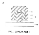
- the structure of a traditional pointing stick 10 is shown in FIG. 1 .
- the pointing stick 10 consists of a substrate 11 , a post 12 , and a rubber cap 14 .
- the substrate 11 is provided with a circuit (not shown) in order to transmit the signal of strain gauges (not shown), disposed on the substrate 11 or the post 12 , to a controlled object, for example, the cursor described above.
- the post 12 is disposed on the substrate 11 , and it is used for being subjected to an external force from the user.
- the rubber cap 14 is disposed on the post 12 .
- the user moves the cursor to a desired position through the pointing stick 10 , he can activate the pointing stick 10 , like the mouse, by pressing its tip end.
- some of the posts 12 may consist of a body 121 and an adapter 122 . Accordingly, the rubber cap 14 is disposed on the adapter 122 .
- the invention provides a tactile pointing stick that can generate a tactile feedback to users.
- the tactile pointing stick of the invention comprises a substrate, a post, a first cap and a second cap.
- the post has a first end, disposed on the substrate, and a second end being free.
- the first cap having an inner bottom surface, is disposed on the post.
- the second cap having a convex portion, is disposed between the inner bottom surface of the first cap and the second end of the post in a manner that the convex portion abuts the post.
- the tactile pointing stick further comprises a hard plate disposed between the inner bottom surface of the first cap and the second cap.
- the post further comprises an adapter, being disposed on the second end of the post and abutting the convex portion.
- the tactile pointing stick of the invention comprises a substrate, a post, a first cap and a second cap.
- the post has a first end, disposed on the substrate, and a second end being free.
- the first cap is disposed on the post.
- the second cap having a convex portion, is disposed between the first cap and the second end of the post in a manner that the convex portion abuts the first cap.
- FIG. 1 is a schematic view depicting a conventional pointing stick
- FIG. 2 a is a schematic view depicting a first embodiment of a tactile pointing stick of the invention
- FIG. 2 b is a schematic view depicting the first embodiment of the tactile pointing stick of the invention, wherein a second cap is subjected to an external force;
- FIG. 3 a is a top view of the second cap of the first embodiment of the invention.
- FIG. 3 b is a front view of the second cap of the first embodiment of the invention.
- FIG. 4 a is a schematic view depicting a second embodiment of a tactile pointing stick of the invention.
- FIG. 4 b is a schematic view depicting the second embodiment of the tactile pointing stick of the invention, wherein a second cap is subjected to an external force.
- the structure of a tactile pointing stick 20 of a first embodiment of the invention is shown in FIG. 2 a and FIG. 2 b .
- the tactile pointing stick 20 comprises a substrate 21 , a post 22 , a first cap 24 , a second cap 25 and a hard plate 26 .
- the post 22 comprises a body 221 and an adapter 222 .
- the adapter 222 fitting the body 221 , is used as a mount when the first cap 24 is disposed on the body 221 .
- the post 22 disposed on the substrate 21 with a first end 22 A and a second end 22 B being free is used for receiving an external force from a user.
- the substrate 21 is provided with a circuit (not shown) in order to transmit the signal of strain gauges (not shown), disposed on the substrate 21 or the post 22 , to a controlled object.
- the first cap 24 having an inner bottom surface 241 , is disposed on the top surface of the second end 22 B of the post 22 .
- the second cap 25 and the hard plate 26 are additionally disposed between the inner bottom surface 241 of the first cap 24 and the adapter 222 .
- the second cap 25 made of elastic material, is dome-shaped.
- the second cap 25 is provided with a convex portion 251 in its central portion so that it can abut the adapter 222 through the convex portion 251 .
- the hard plate 26 is additionally disposed between the inner bottom surface 241 of the first cap 24 and the second cap 25 in order to generate the tactile feedback to the user accurately.
- the convex portion 251 of the second cap 25 moves downward, as shown in FIG. 2 b .
- the second cap 25 When the second cap 25 is deformed, it generates a reacting force to the user. As a result, the user can sense the tactile feedback and operate the tactile pointing stick more precisely.
- the structure of a tactile pointing stick 30 of a second embodiment of the invention is shown in FIG. 4 a and FIG. 4 b .
- the tactile pointing stick 30 comprises a substrate 31 , a post 32 , a first cap 34 , a second cap 35 and a hard plate 36 .
- the post 32 comprises a body 321 and an adapter 322
- the second cap 35 is provided with a convex portion 351 .
- the position and the function of the substrate 31 , the post 32 , the first cap 34 and the hard plate 36 of the present embodiment are the same with the first embodiment; therefore, their description is omitted.
- the difference between the present embodiment and the first embodiment is that the convex portion 351 of the second cap 35 abuts the hard plate 36 .
- the convex portion 351 of the second cap 35 moves downward, as shown in FIG. 4 b .
- the second cap 35 When the second cap 35 is deformed, it generates a reacting force to the user. As a result, the user can sense the tactile feedback and operate the tactile pointing stick more precisely.
- the adapters 222 , 322 of the posts 22 , 32 of the tactile pointing sticks 20 , 30 of the present invention are used as mounts when the first caps 24 , 34 are disposed on the bodies 221 , 321 . Therefore, as long as the size of the bodies 221 , 321 are big enough to fit the first caps 24 , 34 , the second caps 25 , 35 and the hard plate 26 , 36 , the adapters 222 , 322 can be omitted.
Abstract
A tactile pointing stick is provided. A dome-shaped cap, having a convex portion, is additionally disposed between an outer cap and an adapter of a traditional pointing stick. Hence, when a user operates such tactile pointing stick, he can feel feedback, generated by the dome-shaped cap, and operate the tactile pointing stick more precisely. Furthermore, a hard plate is additionally mounted in the pointing stick to ensure the tactile function.
Description
1. Field of the Invention
The invention relates to a tactile pointing stick; in particular, the invention relates to a tactile pointing stick capable of generating a tactile function.
2. Description of the Related Art
In general, the input and output data processing of a computer are carried out interactively with a user via a data input/output device. For example, the data input device may be a keyboard or a pointing device, while the data output device is may be a display screen of a computer that displays such data as characters and graphics. Examples of pointing device include a pointing stick, a digitizer, a mouse, and a track ball.
In recent years, it has become even more popular to use the pointing device, in addition to the keyboard, as the data input device to apply in fields such as data processing. The reason for the popular use of the pointing device can be attributed to the newfound convenience brought by operating systems and application software that employs a free-to-move pointer in response to interactive operations by a user for which the use of the pointing device is essential. For example, Windows operations and icon operations are examples of the interactive operations.
On the other hand, computers today are no longer limited to the bulky desktop type having an independent computer body, keyboard, and display monitor. Recently, portable computers such as the laptop type, notebook type and palm type have become popular, and such portable computers have an integrated computer body, keyboard, and display. The portable computer such as the laptop type can be conveniently carried because it is light and compact.
However, because of the increasing popularity of using such portable computers as the laptop type, the operating condition under which the pointing device is incorporated into a computer has become more diversified. In other words, the pointing device of a desktop type computer is typically operated on the top of a desk while the pointing device for the portable computer is more compact and operable away from the desk.
For this reason, it is desirable that the pointing device used with the portable computer does not require a setup area because the pointing device is integrated with the portable computer. In addition, there is also demand to reduce the setup area of the pointing device of portable computers, where it is more desirable to assemble the pointing device within the computer in order to meet such demand.
The operating theorem of the pointing stick is described as follows. When an operator pushes the pointing stick in an arbitrary direction, a strain dependent on the strain of the pointing stick generated by the force is generated at each strain gauge. Since the resistance of the strain gauge is in proportion to the degree of the strain engaged thereupon, it is possible to determine the moving direction and moving distance of the cursor or pointer on the display screen, based on the changes in the resistance of each of the strain gauges, by detecting the change in the resistance of each strain gauge.
The structure of a traditional pointing stick 10 is shown in FIG. 1. The pointing stick 10 consists of a substrate 11, a post 12, and a rubber cap 14. The substrate 11 is provided with a circuit (not shown) in order to transmit the signal of strain gauges (not shown), disposed on the substrate 11 or the post 12, to a controlled object, for example, the cursor described above. The post 12 is disposed on the substrate 11, and it is used for being subjected to an external force from the user. The rubber cap 14 is disposed on the post 12.
After the user moves the cursor to a desired position through the pointing stick 10, he can activate the pointing stick 10, like the mouse, by pressing its tip end.
Among all kinds of pointing sticks, some of the posts 12 may consist of a body 121 and an adapter 122. Accordingly, the rubber cap 14 is disposed on the adapter 122.
However, since the rubber cap and the post or the adapter are abutted against each other directly without any interface, the user cannot be sure whether his force can activate the pointing stick or not when he presses the tip end of the pointing stick. As a result, the user feels very troubled.
In view of the disadvantages of the aforementioned conventional pointing stick, the invention provides a tactile pointing stick that can generate a tactile feedback to users.
Accordingly, the tactile pointing stick of the invention comprises a substrate, a post, a first cap and a second cap. The post has a first end, disposed on the substrate, and a second end being free. The first cap, having an inner bottom surface, is disposed on the post. The second cap, having a convex portion, is disposed between the inner bottom surface of the first cap and the second end of the post in a manner that the convex portion abuts the post.
Furthermore, the tactile pointing stick further comprises a hard plate disposed between the inner bottom surface of the first cap and the second cap.
Furthermore, the post further comprises an adapter, being disposed on the second end of the post and abutting the convex portion.
In addition, the tactile pointing stick of the invention comprises a substrate, a post, a first cap and a second cap. The post has a first end, disposed on the substrate, and a second end being free. The first cap is disposed on the post. The second cap, having a convex portion, is disposed between the first cap and the second end of the post in a manner that the convex portion abuts the first cap.
The invention is hereinafter described in detail by reference to the accompanying drawings in which:
FIG. 1 is a schematic view depicting a conventional pointing stick;
FIG. 2a is a schematic view depicting a first embodiment of a tactile pointing stick of the invention;
FIG. 2b is a schematic view depicting the first embodiment of the tactile pointing stick of the invention, wherein a second cap is subjected to an external force;
FIG. 3a is a top view of the second cap of the first embodiment of the invention;
FIG. 3b is a front view of the second cap of the first embodiment of the invention;
FIG. 4a is a schematic view depicting a second embodiment of a tactile pointing stick of the invention; and
FIG. 4b is a schematic view depicting the second embodiment of the tactile pointing stick of the invention, wherein a second cap is subjected to an external force.
The structure of a tactile pointing stick 20 of a first embodiment of the invention is shown in FIG. 2a and FIG. 2b. The tactile pointing stick 20 comprises a substrate 21, a post 22, a first cap 24, a second cap 25 and a hard plate 26. The post 22 comprises a body 221 and an adapter 222. The adapter 222, fitting the body 221, is used as a mount when the first cap 24 is disposed on the body 221. The post 22, disposed on the substrate 21 with a first end 22A and a second end 22B being free is used for receiving an external force from a user. The substrate 21 is provided with a circuit (not shown) in order to transmit the signal of strain gauges (not shown), disposed on the substrate 21 or the post 22, to a controlled object. The first cap 24, having an inner bottom surface 241, is disposed on the top surface of the second end 22B of the post 22.
The difference between the traditional pointing stick and the tactile pointing stick of the present embodiment is that the second cap 25 and the hard plate 26 are additionally disposed between the inner bottom surface 241 of the first cap 24 and the adapter 222. As shown in FIG. 3a and FIG. 3b, the second cap 25, made of elastic material, is dome-shaped. Also, the second cap 25 is provided with a convex portion 251 in its central portion so that it can abut the adapter 222 through the convex portion 251.
Furthermore, since most of the first caps 24 are made of soft material, such as rubber, the problem that the user cannot confirm whether he presses the second cap 25 through the first cap 24 or not may occur. Therefore, the hard plate 26 is additionally disposed between the inner bottom surface 241 of the first cap 24 and the second cap 25 in order to generate the tactile feedback to the user accurately.
By means of additionally mounting the second cap 25 and the hard plate 26, when the user presses the tactile pointing stick, the convex portion 251 of the second cap 25 moves downward, as shown in FIG. 2b. When the second cap 25 is deformed, it generates a reacting force to the user. As a result, the user can sense the tactile feedback and operate the tactile pointing stick more precisely.
The structure of a tactile pointing stick 30 of a second embodiment of the invention is shown in FIG. 4a and FIG. 4b. The tactile pointing stick 30 comprises a substrate 31, a post 32, a first cap 34, a second cap 35 and a hard plate 36. The post 32 comprises a body 321 and an adapter 322, and the second cap 35 is provided with a convex portion 351. Among the parts of such tactile pointing stick, the position and the function of the substrate 31, the post 32, the first cap 34 and the hard plate 36 of the present embodiment are the same with the first embodiment; therefore, their description is omitted.
The difference between the present embodiment and the first embodiment is that the convex portion 351 of the second cap 35 abuts the hard plate 36.
By means of additionally mounting the second cap 35 and the hard plate 36, when the user presses the tactile pointing stick 30, the convex portion 351 of the second cap 35 moves downward, as shown in FIG. 4b. When the second cap 35 is deformed, it generates a reacting force to the user. As a result, the user can sense the tactile feedback and operate the tactile pointing stick more precisely.
In addition, it is noted that the adapters 222, 322 of the posts 22, 32 of the tactile pointing sticks 20, 30 of the present invention are used as mounts when the first caps 24, 34 are disposed on the bodies 221, 321. Therefore, as long as the size of the bodies 221, 321 are big enough to fit the first caps 24, 34, the second caps 25,35 and the hard plate 26, 36, the adapters 222, 322 can be omitted.
While the invention has been particularly shown and described with reference to a preferred embodiment, it will be readily appreciated by those of ordinary skill in the art that various changes and modifications may be made without departing from the spirit and scope of the invention. It is intended that the claims be interpreted to cover the disclosed embodiment, those alternatives which have been discussed above, and all equivalents thereto.
Claims (13)
1. A tactile pointing stick, comprising:
a substrate;
a post having a first end, affixed on the substrate, and a second end, being free;
a first cap disposed, having an inner bottom surface, on the second end of the post; and
a second cap, having a convex portion, disposed between the inner bottom surface and the second end of the post in a manner that the convex portion abuts the top surface of the second end of the post.
2. The tactile pointing stick as claimed in claim 1 , further comprising a hard plate disposed between the inner bottom surface of the first cap and the second cap.
3. The tactile pointing stick as claimed in claim 2 , wherein the post further comprises an adapter, and the adapter is disposed between the top surface of the second end of the post and the second cap.
4. A tactile pointing stick, comprising:
a substrate;
a post, having a first end, affixed on the substrate, and a second end being free;
a first cap, having an inner bottom surface, disposed on the second end of the post; and
a second cap, having a convex portion, disposed between the inner bottom surface of the first cap and the second end of the post in a manner that the convex portion abuts the inner bottom surface of the first cap.
5. The tactile pointing stick as claimed in claim 4 , further comprising a hard plate disposed between the inner bottom surface of the first cap and the second cap.
6. The tactile pointing stick as claimed in claim 5 , wherein the post further comprises an adapter, and the adapter is disposed between the top surface of the second end of the post and the second cap.
7. A tactile device of a pointing stick, wherein the pointing stick comprises a substrate and a post disposed on the substrate with a first end and a second end being free, and the tactile device comprises:
a first cap having an inner bottom surface, disposed on the second end of the post; and
a second cap, having a convex portion, disposed between the inner bottom surface of the first cap and the second end of the post.
8. The tactile device of a pointing stick as claimed in claim 7 , wherein the second cap is made of elastic material, and the convex portion is dome-shaped.
9. The tactile device of a pointing stick as claimed in claim 8 , wherein the second cap is disposed between the inner bottom surface of the first cap and the second end of the post in a manner that the convex portion abuts the top surface of the second end of the post.
10. The tactile device of a pointing stick as claimed in claim 9 , further comprising a hard plate disposed between the inner bottom surface of the first cap and the second cap.
11. The tactile device of a pointing stick as claimed in claim 10 , wherein the post further comprises an adapter, and the adapter is disposed between the top surface of the second end of the post and the second cap.
12. The tactile device of a pointing stick as claimed in claim 8 , wherein the second cap is disposed between the inner bottom surface of the first cap and the top surface of the second end of the post in a manner that the convex portion abuts the inner bottom surface of the first cap.
13. The tactile device of a pointing stick as claimed in claim 12 , further comprising a hard plate disposed between the inner bottom surface of the first cap and the second cap.
Applications Claiming Priority (3)
| Application Number | Priority Date | Filing Date | Title |
|---|---|---|---|
| TW89204033U | 2000-03-14 | ||
| TW089204033U TW516685U (en) | 2000-03-14 | 2000-03-14 | Touch-type pointing rod |
| TW89204033 | 2000-03-14 |
Publications (2)
| Publication Number | Publication Date |
|---|---|
| US20010022576A1 US20010022576A1 (en) | 2001-09-20 |
| US6515652B2 true US6515652B2 (en) | 2003-02-04 |
Family
ID=21665241
Family Applications (2)
| Application Number | Title | Priority Date | Filing Date |
|---|---|---|---|
| US09/793,461 Expired - Fee Related US6515652B2 (en) | 2000-03-14 | 2001-02-26 | Tactile pointing stick |
| US10/035,532 Abandoned US20020057270A1 (en) | 2000-03-14 | 2001-11-06 | Virtual reality method |
Family Applications After (1)
| Application Number | Title | Priority Date | Filing Date |
|---|---|---|---|
| US10/035,532 Abandoned US20020057270A1 (en) | 2000-03-14 | 2001-11-06 | Virtual reality method |
Country Status (2)
| Country | Link |
|---|---|
| US (2) | US6515652B2 (en) |
| TW (1) | TW516685U (en) |
Cited By (3)
| Publication number | Priority date | Publication date | Assignee | Title |
|---|---|---|---|---|
| US20090153481A1 (en) * | 2007-12-12 | 2009-06-18 | Gunther Adam M | Data output device having a plurality of key stick devices configured for reading out data to a user and method thereof |
| US20090239665A1 (en) * | 2007-12-31 | 2009-09-24 | Michael Minuto | Brandable thumbstick cover for game controllers |
| US20090315866A1 (en) * | 2008-06-19 | 2009-12-24 | Fujitsu Component Limited | Input apparatus |
Families Citing this family (3)
| Publication number | Priority date | Publication date | Assignee | Title |
|---|---|---|---|---|
| US7542050B2 (en) * | 2004-03-03 | 2009-06-02 | Virtual Iris Studios, Inc. | System for delivering and enabling interactivity with images |
| US7298378B1 (en) | 2004-12-13 | 2007-11-20 | Hagenbuch Andrew M | Virtual reality universe realized as a distributed location network |
| US20190138044A1 (en) * | 2016-04-12 | 2019-05-09 | Mark Slotta | Control Stick Cap with Retention Features |
Citations (3)
| Publication number | Priority date | Publication date | Assignee | Title |
|---|---|---|---|---|
| US6140998A (en) * | 1996-09-26 | 2000-10-31 | Slotta; Mark R. | Method of making cushion for keyboard cursor control stick |
| US6271834B1 (en) * | 1998-05-29 | 2001-08-07 | International Business Machines Corporation | Integrated pointing device having tactile feedback |
| US6400354B1 (en) * | 1999-08-27 | 2002-06-04 | Darfon Electronics Corp. | Pointing stick device that can effectively sense pressure from its cap |
Family Cites Families (6)
| Publication number | Priority date | Publication date | Assignee | Title |
|---|---|---|---|---|
| EP0807352A1 (en) * | 1995-01-31 | 1997-11-19 | Transcenic, Inc | Spatial referenced photography |
| US5874956A (en) * | 1995-11-13 | 1999-02-23 | Platinum Technology | Apparatus and method for three dimensional manipulation of point of view and object |
| US6329963B1 (en) * | 1996-06-05 | 2001-12-11 | Cyberlogic, Inc. | Three-dimensional display system: apparatus and method |
| DE69823116D1 (en) * | 1997-08-05 | 2004-05-19 | Canon Kk | Image processing method and device |
| JP3123501B2 (en) * | 1998-03-16 | 2001-01-15 | 日本電気株式会社 | Space viewpoint controller |
| US6636246B1 (en) * | 2000-03-17 | 2003-10-21 | Vizible.Com Inc. | Three dimensional spatial user interface |
-
2000
- 2000-03-14 TW TW089204033U patent/TW516685U/en unknown
-
2001
- 2001-02-26 US US09/793,461 patent/US6515652B2/en not_active Expired - Fee Related
- 2001-11-06 US US10/035,532 patent/US20020057270A1/en not_active Abandoned
Patent Citations (3)
| Publication number | Priority date | Publication date | Assignee | Title |
|---|---|---|---|---|
| US6140998A (en) * | 1996-09-26 | 2000-10-31 | Slotta; Mark R. | Method of making cushion for keyboard cursor control stick |
| US6271834B1 (en) * | 1998-05-29 | 2001-08-07 | International Business Machines Corporation | Integrated pointing device having tactile feedback |
| US6400354B1 (en) * | 1999-08-27 | 2002-06-04 | Darfon Electronics Corp. | Pointing stick device that can effectively sense pressure from its cap |
Cited By (4)
| Publication number | Priority date | Publication date | Assignee | Title |
|---|---|---|---|---|
| US20090153481A1 (en) * | 2007-12-12 | 2009-06-18 | Gunther Adam M | Data output device having a plurality of key stick devices configured for reading out data to a user and method thereof |
| US20090239665A1 (en) * | 2007-12-31 | 2009-09-24 | Michael Minuto | Brandable thumbstick cover for game controllers |
| US20090315866A1 (en) * | 2008-06-19 | 2009-12-24 | Fujitsu Component Limited | Input apparatus |
| US8508477B2 (en) * | 2008-06-19 | 2013-08-13 | Fujitsu Component Limited | Input apparatus |
Also Published As
| Publication number | Publication date |
|---|---|
| US20020057270A1 (en) | 2002-05-16 |
| US20010022576A1 (en) | 2001-09-20 |
| TW516685U (en) | 2003-01-01 |
Similar Documents
| Publication | Publication Date | Title |
|---|---|---|
| US9612674B2 (en) | Movable track pad with added functionality | |
| US6776546B2 (en) | Method and system for using a keyboard overlay with a touch-sensitive display screen | |
| US5515305A (en) | PDA having chord keyboard input device and method of providing data thereto | |
| US6876354B1 (en) | Keyboard type input device and portable information processor | |
| US20030076302A1 (en) | Joystick input device for palmtop information appliance | |
| US20020075233A1 (en) | Ergonomic pointing device | |
| US20020018048A1 (en) | Z-axis pointing stick with esd protection | |
| KR20090016521A (en) | Integrated input and display device for a mobile computer | |
| GB2335024A (en) | Joystick for portable computer system | |
| US20040041792A1 (en) | Keypad input device | |
| US7808482B2 (en) | Slim mouse | |
| US6515652B2 (en) | Tactile pointing stick | |
| US20040033097A1 (en) | Keyboard and electronic apparatus having the same | |
| US20040174395A1 (en) | Tablet personal computer having functions of switching keyboards and display data | |
| US6796734B2 (en) | Keyless keyboard and a method of using them | |
| GB2299302A (en) | An electronic device with a screen | |
| EP1187156A2 (en) | Instrument with key-activated touch pad | |
| US6304252B1 (en) | Methods for operating input devices for personal computer systems | |
| KR100503056B1 (en) | Touch pad processing apparatus, method thereof and touch pad module in computer system | |
| JPH07302162A (en) | Pointing device | |
| US6582549B2 (en) | Method of manufacturing a pointing stick | |
| US5621435A (en) | Computer user interface for non-dominant hand assisted control | |
| JPH08272525A (en) | Data input device for moving position indicating mark for computer | |
| JPH09282083A (en) | Input device using pointing device | |
| US20010011990A1 (en) | High reliability pointing device for graphical user interface navigation |
Legal Events
| Date | Code | Title | Description |
|---|---|---|---|
| AS | Assignment |
Owner name: DARFON ELECTRONICS CORP., TAIWAN Free format text: ASSIGNMENT OF ASSIGNORS INTEREST;ASSIGNOR:LIU, JIA HUNG;REEL/FRAME:011583/0020 Effective date: 20010216 |
|
| FPAY | Fee payment |
Year of fee payment: 4 |
|
| REMI | Maintenance fee reminder mailed | ||
| LAPS | Lapse for failure to pay maintenance fees | ||
| STCH | Information on status: patent discontinuation |
Free format text: PATENT EXPIRED DUE TO NONPAYMENT OF MAINTENANCE FEES UNDER 37 CFR 1.362 |
|
| FP | Expired due to failure to pay maintenance fee |
Effective date: 20110204 |