US6546187B1 - Digital camera for providing random special effect images and an image processing method therein - Google Patents
Digital camera for providing random special effect images and an image processing method therein Download PDFInfo
- Publication number
- US6546187B1 US6546187B1 US09/219,864 US21986498A US6546187B1 US 6546187 B1 US6546187 B1 US 6546187B1 US 21986498 A US21986498 A US 21986498A US 6546187 B1 US6546187 B1 US 6546187B1
- Authority
- US
- United States
- Prior art keywords
- special effect
- image
- image data
- unaltered
- switch
- Prior art date
- Legal status (The legal status is an assumption and is not a legal conclusion. Google has not performed a legal analysis and makes no representation as to the accuracy of the status listed.)
- Expired - Fee Related
Links
- 230000000694 effects Effects 0.000 title claims abstract description 363
- 238000003672 processing method Methods 0.000 title claims abstract description 18
- 238000003384 imaging method Methods 0.000 claims abstract description 19
- 238000012545 processing Methods 0.000 claims description 21
- 241000238370 Sepia Species 0.000 claims description 3
- 238000000034 method Methods 0.000 abstract description 71
- 238000004891 communication Methods 0.000 abstract description 9
- 238000010586 diagram Methods 0.000 description 8
- 230000006835 compression Effects 0.000 description 7
- 238000007906 compression Methods 0.000 description 7
- 239000000203 mixture Substances 0.000 description 4
- 230000003287 optical effect Effects 0.000 description 3
- 239000002131 composite material Substances 0.000 description 2
- 230000006870 function Effects 0.000 description 2
- 238000003825 pressing Methods 0.000 description 2
- 238000009825 accumulation Methods 0.000 description 1
- 238000010276 construction Methods 0.000 description 1
- 239000004973 liquid crystal related substance Substances 0.000 description 1
- 238000012986 modification Methods 0.000 description 1
- 230000004048 modification Effects 0.000 description 1
- 238000012546 transfer Methods 0.000 description 1
Images


Classifications
-
- H—ELECTRICITY
- H04—ELECTRIC COMMUNICATION TECHNIQUE
- H04N—PICTORIAL COMMUNICATION, e.g. TELEVISION
- H04N5/00—Details of television systems
- H04N5/76—Television signal recording
- H04N5/765—Interface circuits between an apparatus for recording and another apparatus
- H04N5/77—Interface circuits between an apparatus for recording and another apparatus between a recording apparatus and a television camera
- H04N5/772—Interface circuits between an apparatus for recording and another apparatus between a recording apparatus and a television camera the recording apparatus and the television camera being placed in the same enclosure
-
- H—ELECTRICITY
- H04—ELECTRIC COMMUNICATION TECHNIQUE
- H04N—PICTORIAL COMMUNICATION, e.g. TELEVISION
- H04N5/00—Details of television systems
- H04N5/222—Studio circuitry; Studio devices; Studio equipment
- H04N5/262—Studio circuits, e.g. for mixing, switching-over, change of character of image, other special effects ; Cameras specially adapted for the electronic generation of special effects
-
- H—ELECTRICITY
- H04—ELECTRIC COMMUNICATION TECHNIQUE
- H04N—PICTORIAL COMMUNICATION, e.g. TELEVISION
- H04N5/00—Details of television systems
- H04N5/76—Television signal recording
- H04N5/907—Television signal recording using static stores, e.g. storage tubes or semiconductor memories
-
- H—ELECTRICITY
- H04—ELECTRIC COMMUNICATION TECHNIQUE
- H04N—PICTORIAL COMMUNICATION, e.g. TELEVISION
- H04N9/00—Details of colour television systems
- H04N9/79—Processing of colour television signals in connection with recording
- H04N9/80—Transformation of the television signal for recording, e.g. modulation, frequency changing; Inverse transformation for playback
- H04N9/804—Transformation of the television signal for recording, e.g. modulation, frequency changing; Inverse transformation for playback involving pulse code modulation of the colour picture signal components
- H04N9/8042—Transformation of the television signal for recording, e.g. modulation, frequency changing; Inverse transformation for playback involving pulse code modulation of the colour picture signal components involving data reduction
-
- H—ELECTRICITY
- H04—ELECTRIC COMMUNICATION TECHNIQUE
- H04N—PICTORIAL COMMUNICATION, e.g. TELEVISION
- H04N9/00—Details of colour television systems
- H04N9/79—Processing of colour television signals in connection with recording
- H04N9/80—Transformation of the television signal for recording, e.g. modulation, frequency changing; Inverse transformation for playback
- H04N9/82—Transformation of the television signal for recording, e.g. modulation, frequency changing; Inverse transformation for playback the individual colour picture signal components being recorded simultaneously only
- H04N9/8205—Transformation of the television signal for recording, e.g. modulation, frequency changing; Inverse transformation for playback the individual colour picture signal components being recorded simultaneously only involving the multiplexing of an additional signal and the colour video signal
Definitions
- the present invention relates to a digital camera and an image processing method in the digital camera, and more particularly to a digital camera and an image processing method in the digital camera for creating special effect images by performing image-processing that applies special effects to captured images.
- image data representing a subject image (an unaltered image) or unaltered image data obtained by a digital camera is captured into a computer, which image-processes the unaltered image data, thereby creating a special effect image data representing a special effect image by applying the special effects to the unaltered image.
- the special effects such as deformation and soft-focus are applied to the unaltered image with the use of a variety of filters, or the unaltered image is combined with a template image, which is prepared in advance to be used as a background image.
- the computer that is capable of applying the special effects to the unaltered image, and it is difficult for a user who is inexperienced in operating the computer to create the special effect image.
- the present invention has been developed in view of the above-described circumstances, and has as its object the provision of a digital camera and an image processing method in the digital camera, which make it possible to easily obtain interesting and unexpected images.
- the present invention is directed to a digital camera comprising: an imaging system for imaging a subject and converting a subject image into unaltered image data representing an unaltered image of the subject; a special effect selector provided with a random number generator generating a random number, the special effect selector selecting one special effect from a plurality of special effects in accordance with the random number; and a special effect image processor for image-processing the unaltered image data under the special effect selected by the special effect selector to thereby obtain special effect image data representing a special effect image.
- the present invention is directed to an image processing method in a digital camera, comprising the steps of: imaging a subject and converting a subject image into unaltered image data representing an unaltered image of the subject upon receiving a command to image-capture; generating a random number by a random number generator; selecting one special effect from a plurality of special effects in accordance with the random number; and image-processing the unaltered image data under the selected special effect to thereby obtain special effect image data representing a special effect image.
- the randomly-selected special effect is applied to the unaltered image representing the subject image, and thus, it is easy to obtain the unexpected special effect image.
- the unaltered image and/or the special effect image are shown on an image display. It is also possible to provide a display changeover switch such that one of the unaltered image, the special effect image and a mixed image created by mixing the unaltered image with the special effect image, can be selectively shown on the image display.
- the special effect image data may be recorded into a recording medium. It is also possible to record the unaltered image data and special effect data representing the special effect applied to the unaltered image into a recording medium, when an image-capturing switch is operated or when a trigger signal is inputted from external equipment. In this case, the special effect image processor performs the image processing in accordance with the unaltered image data and the special effect data read from the recording medium.
- an image-capturing switch is operated or a trigger signal is inputted from external equipment, the unaltered image data is read from the recording medium for the playback or printing.
- the special effect image data is recorded into the recording medium when a recording switch is turned on.
- the special effect is selected randomly again.
- the recording switch is not turned on, the special effect images changes randomly. Then, the user can record only a favorite special effect image by turning on the recording switch when the favorite special effect image is created and displayed.
- the special effect image data is sent to an external printer so as to print the special effect image on the external printer.
- the special effect is selected randomly again.
- the special effect images changes randomly. Then, the user can print only a favorite special effect image on the external printer by turning on the printing switch when the favorite special effect image is created and displayed.
- the present invention is directed to an image processing method in a digital camera, comprising the steps of: (a) imaging a subject and converting a subject image into unaltered image data representing an unaltered image in a frame; (b) recording the unaltered image data in the frame into a recording medium; (c) repeating the steps (a)-(b) a preset number of times to thereby record the unaltered image data in the preset number of the frames; (d) reading the recorded unaltered image data in one of the preset number of the frames from the recording medium recorded in the step (c); (e) generating a random number by a random number generator; (f) selecting one special effect from a plurality of special effects in accordance with the random number; (g) image-processing the unaltered image data read in the step (d) under the special effect selected in the step (f) to thereby obtain special effect image data representing a special effect image; (h) recording the special effect image data obtained in the step (g) into the recording medium; and (
- the image data of the unaltered images in a plurality of frames is recorded once into the recording medium in continuous image-capturing.
- the special effect is selected for each frame, the image processing is performed in accordance with the selected special effect, and the special effect image data is recorded into the recording medium for the unaltered images in the plurality of frames.
- the present invention is directed to an image processing method in a digital camera, comprising the steps of: (a) imaging a subject and converting a subject image into unaltered image data representing an unaltered image in a frame; (b) generating a random number by a random number generator; (c) selecting one special effect from a plurality of special effects in accordance with the random number; (d) recording a combination of the unaltered image data in the frame and special effect data representing the special effect selected in the step (c) into a recording medium; (e) repeating the steps (a)-(d) a preset number of times to thereby record the preset number of the combinations of the unaltered image data and the special effect data; (f) reading one of the combinations of the unaltered image data and the special effect data recorded in the step (e); (g) image-processing the unaltered image data read in the step (f) under the special effect represented by the special effect data read in the step (f) to thereby obtain special effect image data representing a special effect image
- the special effect data as well as the unaltered image data in a plurality of frames is recorded once into the recording medium in the continuous image-capturing.
- the image processing is performed in accordance with the selected special effect, and the special effect image data is recorded into the recording medium for the unaltered images in the plurality of frames.
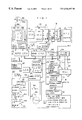
- FIG. 1 is a block diagram illustrating the inner structure of a digital camera according to an embodiment of the present invention
- FIG. 2 is a view of assistance in explaining what is displayed on an LCD in FIG. 1 and the changeover of the display on the LCD;
- FIG. 3 is a view of assistance in explaining a procedure of setting the special effect in a recording mode
- FIG. 4 is a view of assistance in explaining a procedure of setting the special effect in a playback mode
- FIG. 5 is a view of assistance in explaining a procedure of setting the special effect in a printing mode
- FIG. 6 is a view showing an example of a template image representing a sacred lot
- FIG. 7 is a view showing an example of a template image representing an image-capturing place
- FIG. 8 is a view showing an example of an image on a karaoke machine, which is captured as a template image
- FIG. 9 is a view showing an example of an image on a game machine, which is captured as a template image
- FIGS. 10 (A), 10 (B), 10 (C) and 10 (D) are views of assistance in explaining special effect images that are made lean;
- FIGS. 11 (A), 11 (B), 11 (C) and 11 (D) are views of assistance in explaining special effect images that are made fat;
- FIG. 12 is a block diagram showing the flow of the data when the special effect is applied to the unaltered image during the image-recording
- FIG. 13 is a flow chart showing an image-recording mode sequence of applying the special effect to the unaltered image during the image-recording
- FIG. 14 is a flow chart following the flow in FIG. 13;
- FIG. 15 is a flow chart showing a continuous image-capturing mode sequence
- FIG. 16 is a flow chart following the flow in FIG. 15;
- FIG. 17 is a flow chart showing a subroutine for a continuous image-capturing
- FIG. 18 is a block diagram showing the flow of the data when the special effect is applied to the unaltered image during the playback
- FIG. 19 is a flow chart showing a playback mode sequence of applying the special effect to the unaltered image during the playback
- FIG. 20 is a flow chart following the flow in FIG. 19;
- FIG. 21 is a block diagram showing the flow of the data when the special effect is applied to the unaltered image during the printing
- FIG. 22 is a flow chart showing a playback mode sequence of applying the special effect to the unaltered image during the printing.
- FIG. 23 is a flow chart following the flow in FIG. 22 .
- FIG. 1 is a block diagram illustrating the inner structure of a digital camera according to an embodiment of this invention.
- the digital camera comprises a CCD imaging system 10 , a main CPU 20 , an auto CPU 21 , a memory controller 25 , a special effect image processor 26 , an external memory interface 29 , a main memory 40 , a random number generator 42 , a timer 44 , a liquid crystal display (LCD) 46 , a communication interface 48 , an external memory 50 , and a switch part 60 .
- a CCD imaging system 10 As shown in FIG. 1, the digital camera comprises a CCD imaging system 10 , a main CPU 20 , an auto CPU 21 , a memory controller 25 , a special effect image processor 26 , an external memory interface 29 , a main memory 40 , a random number generator 42 , a timer 44 , a liquid crystal display (LCD) 46 , a communication interface 48 , an external memory 50 , and a switch part 60 .
- LCD liquid crystal display
- the CCD imaging system 10 comprises: an imaging optical system 11 including a zoom lens 11 A, an iris 11 B and an optical low pass filter 11 C; a CCD 12 ; an analog processor including a CDS cramp 13 , a gain control amplifier 14 , a gamma ( ⁇ ) corrector 15 and a dot-sequentializer 16 ; and an A/D converter 17 .
- An image of a subject is formed on a light receiving surface of the CCD 12 through the imaging optical system 11 , and each sensor in the CCD 12 converts the image into signal electric charge of which amount corresponds to the quantity of incident light.
- the accumulated signal electric charge is read to a shift register by a read gate pulse sent from a CCD driver (not illustrated), and the signal electric charge is sequentially read out as a voltage signal (an analog image signal) by a register transfer pulse sent from the CCD driver.
- a shutter drain connects to the CCD 12 through a shutter gate. Driving the shutter gate by a shutter gate pulse discharges the accumulated signal electric charge into the shutter drain.
- the CCD 12 has a so-called electronic shutter function of controlling the time (a shutter speed) in which the electric charge is accumulated in each sensor by the shutter gate pulse.
- the analog image signal is read from the CCD 12 , and sent to the CDS cramp 13 .
- the CDS cramp 13 samples and holds the analog image signal for each pixel, and divides the analog image signal into R, G and B color signals, which are sent to the gain control amplifier 14 .
- the gain control amplifier 14 amplifies the inputted R, G and B signals by proper gain so as to adjust their white balance. A detailed description will be given later about the white balance adjustment.
- the gain control amplifier 14 sends the R, G and B signals to the gamma corrector 15 .
- the R, G and B signals are gamma-corrected in the gamma corrector 15 , and they are sent to the dot-sequentializer 16 .
- the dot-sequentializer 16 converts the simultaneously-inputted R, G and B signals into dot-sequential signals, which are sent to the A/D converter 17 .
- the A/D converter 17 converts the dot-sequentially-inputted R, G and B signals into digital signals.
- the digitized R, G and B signals are stored in the main memory 40 such as a dynamic random access memory (DRAM) through the memory controller 25 .
- DRAM dynamic random access memory
- the main CPU 20 connects to the auto CPU 21 , a character generator 22 , an LCD driver 23 , a YC signal generator 24 , the memory controller 25 , the special effect image processor 26 , an encoder 27 , a compression/expansion processor 28 , and the external memory interface 29 via a bus line 30 .
- the main CPU 20 supervises the components in accordance with the inputs from the switch part 60 , the random number generator 42 , the timer 44 , etc.
- the auto CPU 21 performs the controls such as auto-focusing (AF) control, automatic exposure (AE) control, automatic flash control, and automatic white balance (AWB) control.
- the auto CPU 21 receives AF information indicating the object distance from an AF sensor 31 , and receives the R, G and B digital signals through the memory controller 25 .
- the auto CPU 21 drives an AF motor (not illustrated) through an AF motor driver 32 in accordance with the AF information from the AF sensor 31 , so that a focus lens of the zoom lens 11 A can move to a focus position.
- the auto CPU 21 finds AE information that is an integrated value obtained by integrating the R, G and B digital signals in one frame, and AWB information that is color integrated values obtained by integrating the digital signals of each color in one frame.
- the auto CPU 21 sets an iris value and a shutter speed in accordance with the AE information, and drives the iris 11 B by an iris motor (not illustrated) through an iris motor driver 33 so as to achieve the set iris value, and controls the electric charge accumulation time by the electronic shutter so as to achieve the set shutter speed.
- the auto CPU 21 sets the gains for the R, G and B signals in accordance with the AWB information, and controls each gain of the gain control amplifier 14 with an electronic variable resistor (EVR) 34 .
- EMR electronic variable resistor
- the auto CPU 21 also controls a speed light 35 . For example, judging the speed light image-capturing as being performed under a low luminance, the auto CPU 21 outputs a trigger signal to electronically flash a discharge tube 35 A upon the operation of an image-capturing/frame-forwarding switch 61 , which will be described later. Consequently, electric energy stored in a main condenser (not illustrated) is supplied to the discharge tube 35 A, and the discharge tube 35 A flashes.
- a light control sensor 36 which receives the reflected light from the subject, sends a signal indicating the quantity of the received light to the auto CPU 21 . When the quantity of the received light reaches a predetermined one, the auto CPU 21 shuts off the electric energy to the discharge tube 35 A to stop flashing.
- the auto CPU 21 does not only make the speed light 35 flash under the low luminance but also when a compulsory flash switch is turned on.
- the character generator 22 generates character information such as the image-capturing date and a title of the image.
- the captured image can be applied with the characters in accordance with the character information.
- the LCD driver 23 drives the LCD 46 to display an unaltered image of the subject with no special effects, a special effect image created by applying a special effect to the unaltered image, or a mix image of the unaltered image and the special effect image.
- the displayed images can be switched by operating a special effect setting switch 64 and a display changeover switch 68 as shown in FIG. 2 .
- the special effect setting switch 64 is operated to select a time for applying the special effect from a printing time, a playback time and an image-recording time, and if the special effect setting switch 64 is off, no special effect is applied to the unaltered image.
- the special effect setting switch 64 is off at SI in FIG. 2, the unaltered image is displayed on the LCD 46 (S 2 ).
- the special effect setting switch 64 is not off at S 1 , the displayed images on the LCD 46 are changed in accordance with the operation of the display changeover switch 68 (S 3 ). Specifically, when the display changeover switch 68 is switched to the unaltered image, the unaltered image is displayed on the LCD 46 (S 4 ). If the display changeover switch 68 is switched to the special effect image, the special effect image is displayed on the LCD 46 (S 5 ).
- the display changeover switch 68 is switched to an overlapping image A or B, in which the unaltered image is overlapped with the special effect image, the overlapping image A or B is displayed on the LCD 46 . If the display changeover switch 68 is switched to a mix image C in which the unaltered image is mixed with 50% of the special effect image or a mix image D in which the unaltered image is mixed with 25% of the special effect image, the mix image C or D is displayed on the LCD 46 .
- the screen of the LCD 46 is also used to settle the special effect, and this will be described later in detail.
- the YC signal generator 24 generates a luminance signal Y and a chroma signal C (color difference signals B ⁇ Y and R ⁇ Y) from the inputted R, G and B signals.
- the encoder 27 generates an NTSC or PAL color composite video signal in accordance with the inputted luminance signal Y and the color difference signals B ⁇ Y, R ⁇ Y. Then, the encoder 27 outputs the color composite video signal to a video output terminal (not illustrated).
- the special effect image processor 26 applies the special effect to the unaltered image to create the special effect image.
- the special effect image processor 26 contains image data representing a plurality of template images being background for the unaltered image.
- the special effect image processor 26 also has a plurality of image processing filters, which provide the special effects (deformation, soft-focus, etc.). If one of the special effects is selected intentionally or randomly in accordance with the later-described special effect setting, unaltered image data representing the unaltered image and template image data of the selected template image are combined, or the unaltered image data is altered under the selected special effect procedure. Thus, the special effect image processor 26 produces special effect image data representing the special effect image created by applying the special effect to the unaltered image.
- the compression/expansion processor 28 compresses uncompressed data to compressed data or expands the compressed data to the uncompressed data.
- the compression/expansion processor 28 compresses the luminance signals Y and the chroma signals C of one frame, which are generated by the YC signal generator 24 , in a predetermined format. Then, the compressed image data is recorded in the external memory 50 such as a smart medium or a solid-state floppy disk card (SSFDC) through the external memory interface 29 .
- the compression/expansion processor 28 expands the read compressed data to the uncompressed data, and stores the uncompressed data in the main memory 40 through the memory controller 25 .
- the main CPU 20 connects to the random number generator 42 and the timer 44 .
- the random number generator 42 generates and outputs a random number for selecting the special effect randomly, and the timer 44 measures time elapsing since a certain special effect is set.
- the communication interface 48 connects to external equipment such as an external printer, a karaoke (an act of singing along to a music video) machine and a game machine.
- the image data can be transmitted between the external equipment and the digital camera through the communication interface 48 .
- the digital camera can also receive an external trigger signal for image-capturing from the external equipment.
- the switch part 60 comprises the image-capturing/frame-forwarding switch 61 , a mode switch 62 , a file format switch 63 , the special effect setting switch 64 , a printing switch 65 , a settling/recording switch 66 , a special-effect/degree selecting dial 67 , and the display changeover switch 68 .
- the image-capturing/frame-forwarding switch 61 includes a switch SW 1 that is turned on by half-pressing the image-capturing/frame-forwarding switch 61 , and a switch SW 2 that is turned on by full-pressing the image-capturing/frame-forwarding switch 61 .
- the mode switch 62 is operated to select a mode from a printing mode, a playback mode, an image-recording mode, and a power off mode of the digital camera.
- the file format switch 63 is operated to select a format of an image file for recording.
- the special effect setting switch 64 is operated to select a special effect setting time from the printing time, the playback time, and the image-recording time, or the non-setting (off). A detailed description will be given later of the printing switch 65 , the settling/recording switch 66 , the special-effect/degree selecting dial 67 , etc.
- TP 1 is a parameter for setting whether to record the image data upon capturing of the image data or record the image data after enabling the user to confirm the captured image on a preview screen. For instance, the information in TABLE 1 is shown on the screen of the LCD 46 .
- TP 1 is settled and the procedure goes to S 12 .
- TP 2 is a parameter for setting intentionally or randomly the type of the special effect. For instance, the information in TABLE 2 is shown on the screen of the LCD 46 .
- TP2 (PB1) (PR2) Type of special effect 0 Random 1 Sacred lot 2 Image-capturing place 3 Karaoke or game 4 Lean or fat 5 Morphing 6 Soft-focus 7 Blur 8 Deformation 9 Fair-complexioned or dark-complexioned
- FIG. 6 shows an example of one template image among the group of template images representing the sacred lots. Since the template image in FIG. 6 is composed of an area that is common to all the template images, and variable areas such as the number of stars and a lucky direction, an image for the common area and images for the variable areas are stored separately. Then, the images for the variable areas are selected and combined with the image for the common area.
- FIG. 7 shows an example of one template image among the group of template images representing the image-capturing places.
- FIG. 8 shows an example of an image that is sent from the karaoke machine and captured as a template image.
- FIG. 9 shows an example of an image that is sent from the game machine and captured as a template image. The image-capturing date is combined with the template images shown in FIGS. 7-9.
- TP 3 is a parameter for setting intentionally or randomly the degree of the special effect. For instance, the information in TABLE 3 is shown on the screen of the LCD 46 .
- TP 4 is a parameter for setting intentionally or randomly which information is used as the trigger information for selecting one template image from the selected group of the template images. For instance, the information in TABLE 4 is shown on the screen of the LCD 46 .
- TP4 (PB3) (PR4) Trigger information 0 Random 1 RGB 2 YC 3 Lens F (iris value) 4 Lens f (focal length) 5 Shutter speed 6 Quantity of flash light 7 AE information 8 AF information 9 AWB information 10 Karaoke or game
- TP 4 1
- one template image is selected from the selected group of the template images in accordance with the RGB data of the unaltered image. For example, a value indicating the characteristics of the unaltered image is calculated on the basis of the maximum and minimum R, the maximum and minimum G, and the maximum and minimum B of the RGB data. Then, one template image is selected form the selected group of the template images in accordance with the calculated value.
- TP 4 2
- a value indicating the characteristics of the unaltered image is calculated on the basis of the luminance signal Y and the chroma signal C of the unaltered image. Then, one template image is selected form the selected group of the template images in accordance with the calculated value.
- TP 5 is a parameter for setting whether to reselect the special effect, which is set by TP 2 ⁇ TP 4 , at regular intervals (by the timer). For instance, the information in TABLE 5 is shown on the screen of the LCD 46 .
- TP 5 0
- the special effect selected by TP 2 ⁇ TP 4 is not changed with passage of time.
- the special effect can be set and applied to the unaltered image not only in the image-recording mode in FIG. 3, but in the playback mode and the printing mode.
- the special effect setting switch 64 is operated to select the setting of the special effect in the playback mode, the special effect is applied to a reproduced unaltered image.
- the special effect is set in a procedure in FIG. 4 .
- a parameter PB 1 for the special effect type is settled (S 20 ).
- PB 1 is settled in the same manner as S 12 in FIG. 3 (see TABLE 2).
- a settling of a parameter PB 2 for the special effect degree at S 22 , a settling of a parameter PB 3 for the trigger information at S 24 , and a settling of a parameter PB 4 for the timer setting at S 26 are performed in the same manner as S 14 , S 16 , and S 18 , respectively, in FIG. 3 (see TABLES 3, 4 and 5).
- the special effect setting switch 64 is operated to select the setting of the special effect in the printing mode, the special effect is applied to the unaltered image that is read for printing.
- the special effect is set in a procedure in FIG. 5 .
- a parameter PR 1 for setting a printing mode is set (S 30 ).
- PR 1 is a parameter for setting whether to print images one by one by manually operating the printing switch 65 while the user looks at the images on the preview screen or automatically print the images sequentially. For instance, the information in TABLE 6 is shown on the screen of the LCD 46 .
- PR 1 is settled and the procedure goes to S 32 .
- a settling of a parameter PR 2 for the special effect type at S 32 , a settling of a parameter PR 3 for the special effect degree at S 34 , a settling of a parameter PR 4 for the trigger information at S 36 , and a settling of a parameter PR 5 for the timer setting at S 38 are performed in the same manner as S 12 , S 14 , S 16 , and S 18 , respectively, in FIG. 3 (see TABLES 2, 3, 4 and 5).
- FIG. 12 is a block diagram showing the flow of the data when the special effect is applied to the unaltered image during the image-recording.
- FIG. 12 parts similar to those described with reference to FIG. 1 are denoted by the same reference numerals.
- FIGS. 13 and 14 are flow charts showing the procedure of the image-recording mode sequence.
- the image-recording mode sequence starts when the image-recording mode is selected by operating the mode switch 62 .
- the external trigger signal from the external equipment is received or not (S 100 ), and whether the switches SW 1 & SW 2 of the image-capturing/frame-forwarding switch 61 are turned on or not (S 102 & S 104 ). If the receiving of the external trigger signal or the tuned-on of the switches SW 1 & SW 2 is detected, it is judged whether the special effect setting switch 64 is set to the setting of the special effect in the image-recording time or not (S 106 ).
- the image-recording starts immediately and the subject image is captured (S 108 ).
- the image data of one frame which is obtained by the CCD imaging system 10 , is stored in the main memory 40 .
- the LCD driver 23 is driven in accordance with the image data stored in the main memory 40 to display the unaltered image representing the subject image on the LCD 46 (S 110 ).
- the camera information in the image-capturing is embedded in the image file (S 112 ).
- the image data is compressed by the compression/expansion processor 28 , and the compressed image data is recorded in the external memory 50 through the external memory interface 29 (S 114 ).
- the uncompressed image data may also be recorded in the external memory 50 .
- the image-recording mode is the continuous recording mode or not (S 116 ). If the image-recording mode is not the continuous recording mode (in other words, the image-recording mode is a single recording mode), the image-recording mode sequence is completed. If the image-recording mode is the continuous recording mode, the procedure returns to S 100 .
- the single recording mode, the continuous recording mode, etc. can be set on the screen of the LCD 46 .
- TP 2 0
- the random number generator 42 generates a random number within 1 to 9, and the special effect type is set by the random number (S 122 , see TABLE 2). If TP 2 ⁇ 0, the special effect type is set by TP 2 other than 0.
- TP 3 0
- the image-capturing is performed at S 132 , and the procedure goes to S 134 in FIG. 14 .
- the external equipment information is acquired (S 136 ).
- the external equipment information relates to the data on images and scores displayed on the external equipment such as the karaoke machine or the game machine, the data indicating the area where the unaltered image is combined, or the like.
- the template image is selected in accordance with the external equipment information (S 138 ).
- the selected template image is combined with the unaltered image captured at S 132 (S 140 ).
- the character information such as the image-capturing date, which is generated by the character generator 22 , may be combined with them.
- the procedure goes to S 142 , at which whether TP 2 ⁇ 4 or not is judged. If not TP 2 ⁇ 4, one template image is selected from the group of template images selected by TP 2 in accordance with the trigger information selected by TP 4 (S 138 ). The selected template image is combined with the unaltered image captured at S 132 (S 140 ). The special effect image is thus composed from the unaltered image and the template image, and is then displayed on the LCD 46 (S 146 ).
- the unaltered image captured at S 132 is image-processed in accordance with the special effect type set by TP 2 and the special effect degree set by TP 3 (S 144 ).
- the special effect image is thus created from the unaltered image in accordance with the special effect type and the special effect degree, and is then displayed on the LCD 46 (S 146 ).
- TP 1 0
- the camera information (including the camera sensing information) in the image-capturing is embedded in the image file (S 150 ), and it is judged whether the file format switch 63 is positioned at “image file” or “procedure file” (S 152 ).
- the file format switch 63 is operated to select a format of the image file in the recording. If the file format switch 63 is positioned at “image file”, the special effect image data is recorded. If the file format switch 63 is positioned at “procedure file”, special effect data (a procedure file) representing the special effect applied to the unaltered image, as well as the unaltered image data, is recorded.
- the file format switch 63 is positioned at “image file”, the special effect image data is recorded in the external memory 50 (S 154 ). If the file format switch 63 is positioned at “procedure file”, the procedure file representing the special effect applied to the unaltered image, as well as the unaltered image data, is recorded in the external memory 50 (S 156 ).
- the image-recording mode is the continuous recording mode or the single recording mode (S 158 ). If the image-recording mode is the single recording mode, the image-recording mode sequence is completed. If the image-recording mode is the continuous recording mode, the procedure returns to S 100 in FIG. 13 .
- the settling/recording switch 66 is not turned on at S 164 , it is judged whether a preset time has elapsed or not since the currently-applied special effect is set (S 166 ).
- the preset time is suitable for the user to determine whether to record the currently-created special effect image or not by looking at the preview screen of the LCD 46 , which is displayed at S 146 .
- the timer 44 detects the passage of the preset time.
- the special effect applied to the unaltered image is reset at S 168 -S 178 .
- the special effect is set in the same manner as the above-mentioned S 120 -S 130 . After the special effect is reset, the procedure returns to S 134 .
- FIGS. 15 and 16 the same steps as those described with reference to FIGS. 13 and 14 are denoted by the same reference numerals. A description will be given about the processes that are different from the image-recording mode sequence in FIGS. 13 and 14.
- the procedure in FIG. 15 is different from the procedure in FIG. 13 in that S 200 and S 202 are performed instead of S 108 and S 132 .
- the continuous image-capturing is performed as described in a subroutine in FIG. 17 . Specifically, an image is captured (S 210 ), and the image data of one frame, which is obtained by the CCD imaging system 10 , is stored in the main memory 40 (S 212 ). Then, it is judged whether a preset time has elapsed or not (S 214 ).
- the preset time is an interval at which the frames are captured continuously, and it is previously set on the screen of the LCD 46 in the continuous recording mode.
- the preset time has elapsed at S 214 , it is judged whether a preset number of frames have been captured or not (S 216 ).
- the preset number is previously set on the screen on the LCD 46 in the continuous recording mode.
- the procedure returns to S 210 and S 210 -S 216 are repeated. If it is judged at S 216 that the preset number of frames have already been captured, the continuous image-capturing is completed and the procedure returns to the main routine in FIG. 15 .
- the preset number of frames are captured at the preset regular intervals, and the image data of the frames is stored in the main memory 40 .
- the procedure in FIG. 16 is different from the procedure in FIG. 14 in that S 220 is performed instead of S 158 . Specifically, after the special effect image of a certain frame is recorded, it is judged whether all images of the continuously-captured frames have already been processed or not at S 220 . If yes, the procedure is completed, and if not all images of the captured frames have been processed yet, the procedure returns to S 120 in FIG. 15 so that the unaltered image of the next frame can be processed.
- a plurality of continuously-captured images may be recorded as one frame.
- the continuous image-capturing procedure in FIG. 17 is performed instead of S 108 and S 132 in FIG. 13, and the other processes are performed in the same manner as described in FIGS. 13 and 14.
- FIG. 18 is a block diagram showing the flow of the data when the special effect is applied to the unaltered image during the playback.
- FIGS. 19 and 20 are flow charts showing the playback mode sequence.
- parts similar to those described in FIG. 1 are denoted by the same reference numerals, and in FIGS. 19 and 20, steps similar to those described in FIGS. 13 and 14 are denoted by the same reference numerals.
- the playback mode sequence starts when the playback mode is selected by operating the mode switch 62 .
- the image data of one frame is read from the external memory 50 through the external memory interface 29 (S 300 ). Since the playback mode sequence aims to apply the special effect to the unaltered image during the playback, the unaltered image data is read primarily, but if the special effect has already been applied to the unaltered image, the special effect image data, or a combination of the unaltered image data and the procedure file (the special effect data) representing the special effect applied to the unaltered image, is read.
- the read data is stored in the main memory 40 through the compression/expansion processor 28 and the memory controller 25 . If the read image data has been compressed, the data is expanded by the compression/expansion processor 28 .
- the special effect image processor 26 reads the procedure file (S 304 ), and performs the image processing for applying the special effect to the unaltered image (including the combining with the template image) in accordance with the procedure file, thereby creating the special effect image data (S 306 ).
- the LCD driver 23 is driven in accordance with thus created special effect image data, and the special effect image is displayed on the LCD 46 (S 308 ).
- the special effect setting switch 64 is set to the setting of the special effect in the playback time or not (S 310 ). If the special effect setting switch 64 is not set to the setting of the special effect in the playback time, the LCD driver 23 is driven in accordance with the read image data, and the read image is displayed on the LCD 46 (S 308 ).
- the procedure goes to S 312 in FIG. 20 .
- the image processing is performed to apply the special effect to the unaltered image (including the combining with the template image) in accordance with the read image and the set special effect so that the special effect image can be created.
- the created special effect image is displayed on the LCD 46 (S 314 ).
- the settling/recording switch 66 is not turned on at S 318 , it is judged whether the image-capturing/frame-forwarding switch 61 is turned on or not (S 320 ). If the image-capturing/frame-forwarding switch 61 is turned on, the procedure returns to S 300 in FIG. 19 to advance to the next frame and read the image data, etc. of the next frame from the external memory 50 .
- the image-capturing/frame-forwarding switch 61 is not turned on at S 326 , it is judged whether a preset time has elapsed or not since the currently-applied special effect is set (S 330 ). If the preset time has elapsed at S 330 , the special effect applied to the read image is reset at S 168 -S 178 .
- FIG. 21 is a block diagram showing the flow of the data when the special effect is applied to the unaltered image during the printing.
- FIGS. 22 and 23 are flow charts showing the printing mode sequence.
- parts similar to those described in FIG. 1 are denoted by the same reference numerals, and in FIGS. 22 and 23, steps similar to those described in FIGS. 19 and 20 are denoted by the same reference numerals.
- the printing mode sequence starts when the printing mode is selected by operating the mode switch 62 .
- the procedure in FIG. 22 is different from the procedure in FIG. 19 in that S 400 is performed instead of S 310 . Specifically, it is judged whether the special effect setting switch 64 is set to the setting of the special effect in the playback time or not at S 310 in FIG. 19, while it is judged whether the special effect setting switch 64 is set to the setting of the special effect in the printing time or not at S 400 in FIG. 22 .
- the procedure in FIG. 22 is similar to the procedure in FIG. 19 except for S 400 , and a detailed explanation thereof will be omitted.
- the special effect image which is created by applying the special effect to the read image in the printing mode
- PR 1 ⁇ 1 the manual printing mode
- PR 5 the timer setting parameter PR 5 is 0 or not
- PR 5 the procedure goes to S 410
- PR 5 ⁇ 0 the procedure goes to S 414 .
- S 410 and S 414 whether the printing switch 65 is turned on or not is judged. If the printing switch 65 is turned on, the procedure goes to S 412 so that the image can be printed out. After the printout, the procedure goes to S 330 .
- PR 1 ⁇ 0, PR 5 ⁇ 0, and neither the printing switch 65 nor the image-capturing/frame-forwarding switch 61 is turned on different special effects are sequentially applied to the read image at regular intervals to create different special effect images, which are sequentially displayed on the LCD 46 . Then, the user can selectively print a favorite special effect image by operating the printing switch 65 while looking at the preview screen of the LCD 46 in the printing mode.
- the type of the template image combined with the unaltered image is not restricted to this embodiment.
- a template image representing an affinity, biorhythm, etc. may also be adopted.
- the type of the filter (distorting) operation for applying the special effect to the unaltered image is not restricted to this embodiment.
- the filter operations can be performed to apply the following special effects: deformation, sepia tone, black-and-white, shading, vignette, back-light, mosaic, oil printing tone, pointillism, solarization, color subtraction, color balance loss, high key, low key, or the like.
- the filter When the filter is applied, it is possible to select or restrict a filter-applied area. If the filter-applied area is show on the LCD, the user can record the image while looking at the LCD in such a way that the main subject is within the filter-applied area or that the main subject is outside the filter-applied area. For example, the face of the subject may not be filtered, or the eyes, nose or mouth of the subject may be filtered. If the filter-applied area is not designated, the whole image is filtered.
- the randomly-selected special effect is applied to the unaltered image representing the subject image, and it is therefore possible to easily obtain an interesting and unexpected image. If the preset time has elapsed in the state wherein neither the recording switch nor the printing switch is turned on, the special effect may be randomly selected again. For this reason, it is possible to record or print only the image applied with the favorite special effect.
Abstract
Description
| TABLE 1 | ||
| | Recording time | |
| 0 | Record the image data upon the image-capturing | |
| 1 | Record the image data after confirming the image on a preview | |
| screen | ||
| TABLE 2 | |||
| TP2 | |||
| (PB1) | |||
| (PR2) | Type of |
||
| 0 | |
||
| 1 | Sacred lot | ||
| 2 | Image-capturing place | ||
| 3 | Karaoke or game | ||
| 4 | Lean or fat | ||
| 5 | |
||
| 6 | Soft-focus | ||
| 7 | Blur | ||
| 8 | Deformation | ||
| 9 | Fair-complexioned or dark-complexioned | ||
| TABLE 3 | |||
| TP3 | |||
| (PB2) | |||
| (PR3) | Degree of |
||
| 0 | |
||
| 1 | Much | ||
| 2 | Medium | ||
| 3 | Little | ||
| TABLE 4 | |||
| TP4 | |||
| (PB3) | |||
| (PR4) | |
||
| 0 | |
||
| 1 | RGB | ||
| 2 | YC | ||
| 3 | Lens F (iris value) | ||
| 4 | Lens f (focal length) | ||
| 5 | |
||
| 6 | Quantity of flash light | ||
| 7 | AE information | ||
| 8 | AF information | ||
| 9 | |
||
| 10 | Karaoke or game | ||
| TABLE 5 | |||
| TP5 | |||
| (PB4) | |||
| (PR5) | Timer setting | ||
| 0 | Not reselecting by |
||
| 1 | Reselecting by timer | ||
| TABLE 6 | |||
| | Printing mode | ||
| 0 | |
||
| 1 | Automatic printing mode | ||
Claims (32)
Applications Claiming Priority (2)
| Application Number | Priority Date | Filing Date | Title |
|---|---|---|---|
| JP9-360089 | 1997-12-26 | ||
| JP36008997A JP4412749B2 (en) | 1997-12-26 | 1997-12-26 | Digital camera and image processing method in digital camera |
Publications (1)
| Publication Number | Publication Date |
|---|---|
| US6546187B1 true US6546187B1 (en) | 2003-04-08 |
Family
ID=18467853
Family Applications (1)
| Application Number | Title | Priority Date | Filing Date |
|---|---|---|---|
| US09/219,864 Expired - Fee Related US6546187B1 (en) | 1997-12-26 | 1998-12-24 | Digital camera for providing random special effect images and an image processing method therein |
Country Status (2)
| Country | Link |
|---|---|
| US (1) | US6546187B1 (en) |
| JP (1) | JP4412749B2 (en) |
Cited By (31)
| Publication number | Priority date | Publication date | Assignee | Title |
|---|---|---|---|---|
| US20020163531A1 (en) * | 2000-08-30 | 2002-11-07 | Keigo Ihara | Effect adding device, effect adding method, effect adding program, storage medium where effect adding program is stored |
| US20040004665A1 (en) * | 2002-06-25 | 2004-01-08 | Kotaro Kashiwa | System for creating content using content project data |
| US20040027465A1 (en) * | 2002-08-07 | 2004-02-12 | Eastman Kodak Company | Cameras, other imaging devices, and methods having non-uniform image remapping using a small data-set of distortion vectors |
| US20050084252A1 (en) * | 2003-08-12 | 2005-04-21 | Mayumi Satou | Disc recording and/or reproducing apparatus |
| US20050158030A1 (en) * | 1999-12-10 | 2005-07-21 | Nishikawa Yuko S. | Auto title frames generation method and apparatus |
| US20050219384A1 (en) * | 2004-03-31 | 2005-10-06 | Magix Ag | System and method of creating multilayered digital images in real time |
| US20060139477A1 (en) * | 2004-12-24 | 2006-06-29 | Ryunosuke Iijima | Image pickup apparatus and method of controlling same |
| US20060158519A1 (en) * | 1997-07-15 | 2006-07-20 | Silverbrook Research Pty Ltd | Digital camera having parallel processing controller |
| US20060248030A1 (en) * | 2005-04-30 | 2006-11-02 | Stmicroelectronics Ltd. | Method and apparatus for processing image data |
| WO2007088447A1 (en) * | 2006-02-03 | 2007-08-09 | Nokia Corporation | Gaming device, method, and computer program product for modifying input to a native application to present modified output |
| US7362946B1 (en) * | 1999-04-12 | 2008-04-22 | Canon Kabushiki Kaisha | Automated visual image editing system |
| CN100450166C (en) * | 2004-05-31 | 2009-01-07 | 佳能株式会社 | Apparatus and method for image processing |
| US8096642B2 (en) | 1997-08-11 | 2012-01-17 | Silverbrook Research Pty Ltd | Inkjet nozzle with paddle layer arranged between first and second wafers |
| US8102568B2 (en) | 1997-07-15 | 2012-01-24 | Silverbrook Research Pty Ltd | System for creating garments using camera and encoded card |
| US20120113296A1 (en) * | 2010-11-08 | 2012-05-10 | Keiji Kunishige | Imaging device and imaging method |
| US8274665B2 (en) | 1997-07-15 | 2012-09-25 | Silverbrook Research Pty Ltd | Image sensing and printing device |
| US8285137B2 (en) | 1997-07-15 | 2012-10-09 | Silverbrook Research Pty Ltd | Digital camera system for simultaneous printing and magnetic recording |
| US20130083211A1 (en) * | 2011-10-04 | 2013-04-04 | Keiji Kunishige | Imaging device and imaging method |
| US8421869B2 (en) | 1997-07-15 | 2013-04-16 | Google Inc. | Camera system for with velocity sensor and de-blurring processor |
| US20140071307A1 (en) * | 2012-09-11 | 2014-03-13 | Olympus Imaging Corp. | Image generation apparatus, imaging apparatus comprising the same, image generation method, and storage medium storing image generation program |
| US8789939B2 (en) | 1998-11-09 | 2014-07-29 | Google Inc. | Print media cartridge with ink supply manifold |
| US8866923B2 (en) | 1999-05-25 | 2014-10-21 | Google Inc. | Modular camera and printer |
| CN104125411A (en) * | 2013-04-26 | 2014-10-29 | 奥林巴斯映像株式会社 | Imaging apparatus, image processing apparatus, and image processing method |
| US8896724B2 (en) | 1997-07-15 | 2014-11-25 | Google Inc. | Camera system to facilitate a cascade of imaging effects |
| US8902333B2 (en) | 1997-07-15 | 2014-12-02 | Google Inc. | Image processing method using sensed eye position |
| US8908075B2 (en) | 1997-07-15 | 2014-12-09 | Google Inc. | Image capture and processing integrated circuit for a camera |
| US8934033B2 (en) * | 2011-10-06 | 2015-01-13 | Olympus Imaging Corp. | Imaging device, imaging method, and computer readable recording medium |
| US8936196B2 (en) | 1997-07-15 | 2015-01-20 | Google Inc. | Camera unit incorporating program script scanner |
| CN107770450A (en) * | 2017-11-08 | 2018-03-06 | 光锐恒宇(北京)科技有限公司 | Image processing method, device and terminal device |
| US9967467B2 (en) * | 2015-05-29 | 2018-05-08 | Oath Inc. | Image capture with display context |
| CN109157831A (en) * | 2018-08-06 | 2019-01-08 | 光锐恒宇(北京)科技有限公司 | Implementation method, device, intelligent terminal and the computer readable storage medium of game |
Families Citing this family (12)
| Publication number | Priority date | Publication date | Assignee | Title |
|---|---|---|---|---|
| JP3755376B2 (en) * | 2000-03-21 | 2006-03-15 | セイコーエプソン株式会社 | Printing device |
| JP2004112600A (en) * | 2002-09-20 | 2004-04-08 | Ricoh Co Ltd | Imaging control system |
| US7528868B2 (en) | 2003-12-18 | 2009-05-05 | Eastman Kodak Company | Image metadata attachment |
| JP4535268B2 (en) * | 2005-02-18 | 2010-09-01 | 日本電気株式会社 | Imaging apparatus and imaging system |
| JP2007079636A (en) * | 2005-09-09 | 2007-03-29 | Seiko Epson Corp | Image processing apparatus, image processing method and program |
| JP4863497B2 (en) * | 2007-04-26 | 2012-01-25 | キヤノン株式会社 | Imaging apparatus, control method therefor, and program |
| JP2009218842A (en) * | 2008-03-10 | 2009-09-24 | Nec Access Technica Ltd | Mobile information terminal device provided with camera, its image processing method and program |
| JP2011044883A (en) * | 2009-08-20 | 2011-03-03 | Nihon System Kaihatsu Co Ltd | Digital camera with image synthesis function |
| JP5484958B2 (en) * | 2010-02-26 | 2014-05-07 | オリンパスイメージング株式会社 | Digital camera and control method thereof |
| JP2012124608A (en) * | 2010-12-06 | 2012-06-28 | Olympus Imaging Corp | Camera |
| JP5742336B2 (en) * | 2011-03-18 | 2015-07-01 | 株式会社ニコン | IMAGING DEVICE AND IMAGING DEVICE CONTROL PROGRAM |
| JP2014075762A (en) * | 2012-10-05 | 2014-04-24 | Nikon Corp | Imaging apparatus |
Citations (14)
| Publication number | Priority date | Publication date | Assignee | Title |
|---|---|---|---|---|
| US5228859A (en) * | 1990-09-17 | 1993-07-20 | Interactive Training Technologies | Interactive educational and training system with concurrent digitized sound and video output |
| US5293540A (en) * | 1991-07-29 | 1994-03-08 | Nview Corporation | Method and apparatus for merging independently generated internal video with external video |
| US5457755A (en) * | 1989-02-08 | 1995-10-10 | Canon Kabushiki Kaisha | Figure processing apparatus |
| US5513315A (en) * | 1992-12-22 | 1996-04-30 | Microsoft Corporation | System and method for automatic testing of computer software |
| US5555098A (en) * | 1991-12-05 | 1996-09-10 | Eastman Kodak Company | Method and apparatus for providing multiple programmed audio/still image presentations from a digital disc image player |
| US5633678A (en) * | 1995-12-20 | 1997-05-27 | Eastman Kodak Company | Electronic still camera for capturing and categorizing images |
| US5664216A (en) * | 1994-03-22 | 1997-09-02 | Blumenau; Trevor | Iconic audiovisual data editing environment |
| US5692113A (en) * | 1995-05-17 | 1997-11-25 | Olympus Optical Co., Ltd. | Data reproduction system for reproducing and outputting multimedia information using a printer |
| US5696850A (en) * | 1995-12-21 | 1997-12-09 | Eastman Kodak Company | Automatic image sharpening in an electronic imaging system |
| US5767920A (en) * | 1995-11-28 | 1998-06-16 | Samsung Electronics Co., Ltd. | Coloring device and method for specific region on a video display screen |
| US5905539A (en) * | 1990-09-24 | 1999-05-18 | Tektronix, Inc. | Method and apparatus for generating a wipe solid |
| US6085019A (en) * | 1995-09-08 | 2000-07-04 | Sony Corporation | Apparatus and method for recording and reproducing video data to and from a record medium |
| US6157771A (en) * | 1996-11-15 | 2000-12-05 | Futuretel, Inc. | Method and apparatus for seeking within audiovisual files |
| US6248944B1 (en) * | 1998-09-24 | 2001-06-19 | Yamaha Corporation | Apparatus for switching picture items of different types by suitable transition modes |
-
1997
- 1997-12-26 JP JP36008997A patent/JP4412749B2/en not_active Expired - Fee Related
-
1998
- 1998-12-24 US US09/219,864 patent/US6546187B1/en not_active Expired - Fee Related
Patent Citations (14)
| Publication number | Priority date | Publication date | Assignee | Title |
|---|---|---|---|---|
| US5457755A (en) * | 1989-02-08 | 1995-10-10 | Canon Kabushiki Kaisha | Figure processing apparatus |
| US5228859A (en) * | 1990-09-17 | 1993-07-20 | Interactive Training Technologies | Interactive educational and training system with concurrent digitized sound and video output |
| US5905539A (en) * | 1990-09-24 | 1999-05-18 | Tektronix, Inc. | Method and apparatus for generating a wipe solid |
| US5293540A (en) * | 1991-07-29 | 1994-03-08 | Nview Corporation | Method and apparatus for merging independently generated internal video with external video |
| US5555098A (en) * | 1991-12-05 | 1996-09-10 | Eastman Kodak Company | Method and apparatus for providing multiple programmed audio/still image presentations from a digital disc image player |
| US5513315A (en) * | 1992-12-22 | 1996-04-30 | Microsoft Corporation | System and method for automatic testing of computer software |
| US5664216A (en) * | 1994-03-22 | 1997-09-02 | Blumenau; Trevor | Iconic audiovisual data editing environment |
| US5692113A (en) * | 1995-05-17 | 1997-11-25 | Olympus Optical Co., Ltd. | Data reproduction system for reproducing and outputting multimedia information using a printer |
| US6085019A (en) * | 1995-09-08 | 2000-07-04 | Sony Corporation | Apparatus and method for recording and reproducing video data to and from a record medium |
| US5767920A (en) * | 1995-11-28 | 1998-06-16 | Samsung Electronics Co., Ltd. | Coloring device and method for specific region on a video display screen |
| US5633678A (en) * | 1995-12-20 | 1997-05-27 | Eastman Kodak Company | Electronic still camera for capturing and categorizing images |
| US5696850A (en) * | 1995-12-21 | 1997-12-09 | Eastman Kodak Company | Automatic image sharpening in an electronic imaging system |
| US6157771A (en) * | 1996-11-15 | 2000-12-05 | Futuretel, Inc. | Method and apparatus for seeking within audiovisual files |
| US6248944B1 (en) * | 1998-09-24 | 2001-06-19 | Yamaha Corporation | Apparatus for switching picture items of different types by suitable transition modes |
Cited By (95)
| Publication number | Priority date | Publication date | Assignee | Title |
|---|---|---|---|---|
| US8902340B2 (en) | 1997-07-12 | 2014-12-02 | Google Inc. | Multi-core image processor for portable device |
| US9544451B2 (en) | 1997-07-12 | 2017-01-10 | Google Inc. | Multi-core image processor for portable device |
| US9338312B2 (en) | 1997-07-12 | 2016-05-10 | Google Inc. | Portable handheld device with multi-core image processor |
| US8947592B2 (en) | 1997-07-12 | 2015-02-03 | Google Inc. | Handheld imaging device with image processor provided with multiple parallel processing units |
| US9124736B2 (en) | 1997-07-15 | 2015-09-01 | Google Inc. | Portable hand-held device for displaying oriented images |
| US8913182B2 (en) | 1997-07-15 | 2014-12-16 | Google Inc. | Portable hand-held device having networked quad core processor |
| US9584681B2 (en) | 1997-07-15 | 2017-02-28 | Google Inc. | Handheld imaging device incorporating multi-core image processor |
| US20060158519A1 (en) * | 1997-07-15 | 2006-07-20 | Silverbrook Research Pty Ltd | Digital camera having parallel processing controller |
| US9560221B2 (en) | 1997-07-15 | 2017-01-31 | Google Inc. | Handheld imaging device with VLIW image processor |
| US9432529B2 (en) | 1997-07-15 | 2016-08-30 | Google Inc. | Portable handheld device with multi-core microcoded image processor |
| US9237244B2 (en) | 1997-07-15 | 2016-01-12 | Google Inc. | Handheld digital camera device with orientation sensing and decoding capabilities |
| US9219832B2 (en) | 1997-07-15 | 2015-12-22 | Google Inc. | Portable handheld device with multi-core image processor |
| US9197767B2 (en) | 1997-07-15 | 2015-11-24 | Google Inc. | Digital camera having image processor and printer |
| US9191530B2 (en) | 1997-07-15 | 2015-11-17 | Google Inc. | Portable hand-held device having quad core image processor |
| US9191529B2 (en) | 1997-07-15 | 2015-11-17 | Google Inc | Quad-core camera processor |
| US9185246B2 (en) | 1997-07-15 | 2015-11-10 | Google Inc. | Camera system comprising color display and processor for decoding data blocks in printed coding pattern |
| US9185247B2 (en) | 1997-07-15 | 2015-11-10 | Google Inc. | Central processor with multiple programmable processor units |
| US9179020B2 (en) | 1997-07-15 | 2015-11-03 | Google Inc. | Handheld imaging device with integrated chip incorporating on shared wafer image processor and central processor |
| US9168761B2 (en) | 1997-07-15 | 2015-10-27 | Google Inc. | Disposable digital camera with printing assembly |
| US7826088B2 (en) * | 1997-07-15 | 2010-11-02 | Silverbrook Research Pty Ltd | Digital camera having parallel processing controller |
| US9148530B2 (en) | 1997-07-15 | 2015-09-29 | Google Inc. | Handheld imaging device with multi-core image processor integrating common bus interface and dedicated image sensor interface |
| US9143636B2 (en) | 1997-07-15 | 2015-09-22 | Google Inc. | Portable device with dual image sensors and quad-core processor |
| US8102568B2 (en) | 1997-07-15 | 2012-01-24 | Silverbrook Research Pty Ltd | System for creating garments using camera and encoded card |
| US9143635B2 (en) | 1997-07-15 | 2015-09-22 | Google Inc. | Camera with linked parallel processor cores |
| US9137397B2 (en) | 1997-07-15 | 2015-09-15 | Google Inc. | Image sensing and printing device |
| US9137398B2 (en) | 1997-07-15 | 2015-09-15 | Google Inc. | Multi-core processor for portable device with dual image sensors |
| US8913151B2 (en) | 1997-07-15 | 2014-12-16 | Google Inc. | Digital camera with quad core processor |
| US8285137B2 (en) | 1997-07-15 | 2012-10-09 | Silverbrook Research Pty Ltd | Digital camera system for simultaneous printing and magnetic recording |
| US9131083B2 (en) | 1997-07-15 | 2015-09-08 | Google Inc. | Portable imaging device with multi-core processor |
| US8421869B2 (en) | 1997-07-15 | 2013-04-16 | Google Inc. | Camera system for with velocity sensor and de-blurring processor |
| US8908069B2 (en) | 1997-07-15 | 2014-12-09 | Google Inc. | Handheld imaging device with quad-core image processor integrating image sensor interface |
| US9060128B2 (en) | 1997-07-15 | 2015-06-16 | Google Inc. | Portable hand-held device for manipulating images |
| US9055221B2 (en) | 1997-07-15 | 2015-06-09 | Google Inc. | Portable hand-held device for deblurring sensed images |
| US8823823B2 (en) | 1997-07-15 | 2014-09-02 | Google Inc. | Portable imaging device with multi-core processor and orientation sensor |
| US8836809B2 (en) | 1997-07-15 | 2014-09-16 | Google Inc. | Quad-core image processor for facial detection |
| US8953061B2 (en) | 1997-07-15 | 2015-02-10 | Google Inc. | Image capture device with linked multi-core processor and orientation sensor |
| US8953178B2 (en) | 1997-07-15 | 2015-02-10 | Google Inc. | Camera system with color display and processor for reed-solomon decoding |
| US8866926B2 (en) | 1997-07-15 | 2014-10-21 | Google Inc. | Multi-core processor for hand-held, image capture device |
| US8953060B2 (en) | 1997-07-15 | 2015-02-10 | Google Inc. | Hand held image capture device with multi-core processor and wireless interface to input device |
| US8947679B2 (en) | 1997-07-15 | 2015-02-03 | Google Inc. | Portable handheld device with multi-core microcoded image processor |
| US8896724B2 (en) | 1997-07-15 | 2014-11-25 | Google Inc. | Camera system to facilitate a cascade of imaging effects |
| US8896720B2 (en) | 1997-07-15 | 2014-11-25 | Google Inc. | Hand held image capture device with multi-core processor for facial detection |
| US8902333B2 (en) | 1997-07-15 | 2014-12-02 | Google Inc. | Image processing method using sensed eye position |
| US8902357B2 (en) | 1997-07-15 | 2014-12-02 | Google Inc. | Quad-core image processor |
| US8902324B2 (en) | 1997-07-15 | 2014-12-02 | Google Inc. | Quad-core image processor for device with image display |
| US8936196B2 (en) | 1997-07-15 | 2015-01-20 | Google Inc. | Camera unit incorporating program script scanner |
| US8908075B2 (en) | 1997-07-15 | 2014-12-09 | Google Inc. | Image capture and processing integrated circuit for a camera |
| US8908051B2 (en) | 1997-07-15 | 2014-12-09 | Google Inc. | Handheld imaging device with system-on-chip microcontroller incorporating on shared wafer image processor and image sensor |
| US9124737B2 (en) | 1997-07-15 | 2015-09-01 | Google Inc. | Portable device with image sensor and quad-core processor for multi-point focus image capture |
| US8937727B2 (en) | 1997-07-15 | 2015-01-20 | Google Inc. | Portable handheld device with multi-core image processor |
| US8274665B2 (en) | 1997-07-15 | 2012-09-25 | Silverbrook Research Pty Ltd | Image sensing and printing device |
| US8913137B2 (en) | 1997-07-15 | 2014-12-16 | Google Inc. | Handheld imaging device with multi-core image processor integrating image sensor interface |
| US8922791B2 (en) | 1997-07-15 | 2014-12-30 | Google Inc. | Camera system with color display and processor for Reed-Solomon decoding |
| US8922670B2 (en) | 1997-07-15 | 2014-12-30 | Google Inc. | Portable hand-held device having stereoscopic image camera |
| US8928897B2 (en) | 1997-07-15 | 2015-01-06 | Google Inc. | Portable handheld device with multi-core image processor |
| US8934027B2 (en) | 1997-07-15 | 2015-01-13 | Google Inc. | Portable device with image sensors and multi-core processor |
| US8934053B2 (en) | 1997-07-15 | 2015-01-13 | Google Inc. | Hand-held quad core processing apparatus |
| US8096642B2 (en) | 1997-08-11 | 2012-01-17 | Silverbrook Research Pty Ltd | Inkjet nozzle with paddle layer arranged between first and second wafers |
| US8789939B2 (en) | 1998-11-09 | 2014-07-29 | Google Inc. | Print media cartridge with ink supply manifold |
| US7362946B1 (en) * | 1999-04-12 | 2008-04-22 | Canon Kabushiki Kaisha | Automated visual image editing system |
| US8866923B2 (en) | 1999-05-25 | 2014-10-21 | Google Inc. | Modular camera and printer |
| US20050158030A1 (en) * | 1999-12-10 | 2005-07-21 | Nishikawa Yuko S. | Auto title frames generation method and apparatus |
| US7415189B2 (en) * | 1999-12-10 | 2008-08-19 | Sony Corporation | Auto title frames generation method and apparatus |
| US7103840B2 (en) * | 2000-08-30 | 2006-09-05 | Sony Corporation | Effect adding device, effect adding method, effect adding program, storage medium where effect adding program is stored |
| US20020163531A1 (en) * | 2000-08-30 | 2002-11-07 | Keigo Ihara | Effect adding device, effect adding method, effect adding program, storage medium where effect adding program is stored |
| US8244104B2 (en) * | 2002-06-25 | 2012-08-14 | Sony Corporation | System for creating content using content project data |
| US20040004665A1 (en) * | 2002-06-25 | 2004-01-08 | Kotaro Kashiwa | System for creating content using content project data |
| US20040027465A1 (en) * | 2002-08-07 | 2004-02-12 | Eastman Kodak Company | Cameras, other imaging devices, and methods having non-uniform image remapping using a small data-set of distortion vectors |
| US7301568B2 (en) * | 2002-08-07 | 2007-11-27 | Smith Craig M | Cameras, other imaging devices, and methods having non-uniform image remapping using a small data-set of distortion vectors |
| US7675556B2 (en) | 2002-08-07 | 2010-03-09 | Eastman Kodak Company | Cameras, other imaging devices, and methods having non-uniform image remapping using a small data-set of distortion vectors |
| US7577338B2 (en) * | 2003-08-12 | 2009-08-18 | Sony Corporation | Disc recording and/or reproducing apparatus having a case with a partition wall for forming two chambers |
| US20050084252A1 (en) * | 2003-08-12 | 2005-04-21 | Mayumi Satou | Disc recording and/or reproducing apparatus |
| US20050219384A1 (en) * | 2004-03-31 | 2005-10-06 | Magix Ag | System and method of creating multilayered digital images in real time |
| US7391445B2 (en) | 2004-03-31 | 2008-06-24 | Magix Ag | System and method of creating multilayered digital images in real time |
| US8203626B2 (en) | 2004-05-31 | 2012-06-19 | Canon Kabushiki Kaisha | Apparatus and method for image processing with special effect application to image and display of animation image |
| CN100450166C (en) * | 2004-05-31 | 2009-01-07 | 佳能株式会社 | Apparatus and method for image processing |
| US7667744B2 (en) * | 2004-12-24 | 2010-02-23 | Canon Kabushiki Kaisha | Image pickup apparatus and method of controlling same |
| US20060139477A1 (en) * | 2004-12-24 | 2006-06-29 | Ryunosuke Iijima | Image pickup apparatus and method of controlling same |
| US20060248030A1 (en) * | 2005-04-30 | 2006-11-02 | Stmicroelectronics Ltd. | Method and apparatus for processing image data |
| US8049794B2 (en) * | 2005-04-30 | 2011-11-01 | Stmicroelectronics Ltd. | Method and apparatus for processing image data |
| WO2007088447A1 (en) * | 2006-02-03 | 2007-08-09 | Nokia Corporation | Gaming device, method, and computer program product for modifying input to a native application to present modified output |
| US20120113296A1 (en) * | 2010-11-08 | 2012-05-10 | Keiji Kunishige | Imaging device and imaging method |
| US8842200B2 (en) * | 2010-11-08 | 2014-09-23 | Olympus Imaging Corp. | Imaging device and imaging method capable of bright spot processing |
| US20130083211A1 (en) * | 2011-10-04 | 2013-04-04 | Keiji Kunishige | Imaging device and imaging method |
| US8957982B2 (en) * | 2011-10-04 | 2015-02-17 | Olympus Imaging Corp. | Imaging device and imaging method |
| US8934033B2 (en) * | 2011-10-06 | 2015-01-13 | Olympus Imaging Corp. | Imaging device, imaging method, and computer readable recording medium |
| CN103685915A (en) * | 2012-09-11 | 2014-03-26 | 奥林巴斯映像株式会社 | Image generation apparatus, imaging apparatus comprising the same and image generation method |
| CN103685915B (en) * | 2012-09-11 | 2017-06-30 | 奥林巴斯株式会社 | Video generation device, camera head and image generating method with the device |
| US20140071307A1 (en) * | 2012-09-11 | 2014-03-13 | Olympus Imaging Corp. | Image generation apparatus, imaging apparatus comprising the same, image generation method, and storage medium storing image generation program |
| US9402037B2 (en) * | 2013-04-26 | 2016-07-26 | Olympus Corporation | Imaging apparatus, image processing apparatus, and image processing method for generating random special effects |
| US20140320692A1 (en) * | 2013-04-26 | 2014-10-30 | Olympus Imaging Corp. | Imaging apparatus, image processing apparatus, and image processing method |
| CN104125411A (en) * | 2013-04-26 | 2014-10-29 | 奥林巴斯映像株式会社 | Imaging apparatus, image processing apparatus, and image processing method |
| US9967467B2 (en) * | 2015-05-29 | 2018-05-08 | Oath Inc. | Image capture with display context |
| CN107770450A (en) * | 2017-11-08 | 2018-03-06 | 光锐恒宇(北京)科技有限公司 | Image processing method, device and terminal device |
| CN109157831A (en) * | 2018-08-06 | 2019-01-08 | 光锐恒宇(北京)科技有限公司 | Implementation method, device, intelligent terminal and the computer readable storage medium of game |
Also Published As
| Publication number | Publication date |
|---|---|
| JP4412749B2 (en) | 2010-02-10 |
| JPH11196306A (en) | 1999-07-21 |
Similar Documents
| Publication | Publication Date | Title |
|---|---|---|
| US6546187B1 (en) | Digital camera for providing random special effect images and an image processing method therein | |
| US7199829B2 (en) | Device and method for processing unprocessed image data based on image property parameters | |
| US6819359B1 (en) | Method and apparatus for controlling the processing of signals containing defective pixels in accordance with imaging operation mode | |
| US20090262219A1 (en) | Digital Camera | |
| US20010043277A1 (en) | Electronic camera | |
| JP4730553B2 (en) | Imaging apparatus and exposure control method | |
| CN1992820A (en) | Digital camera with face detection function for facilitating exposure compensation | |
| JP2957977B2 (en) | Video camera | |
| US5532740A (en) | Image-data recording device and image-reproduction device for an electronic still camera | |
| JP2004328117A (en) | Digital camera and photographing control method | |
| US7719727B2 (en) | Image reproducing apparatus for preventing white balance offset and solid-state imaging apparatus | |
| US7292268B2 (en) | Image processing system, image capturing apparatus, image processing apparatus, and image processing method for performing edge enhancement | |
| US7570294B2 (en) | Digital camera | |
| JP3590242B2 (en) | Electronic imaging device | |
| JP4439173B2 (en) | Digital camera and information terminal | |
| JP2002209125A (en) | Digital camera | |
| JP2005033255A (en) | Image processing method of digital image, digital camera and print system | |
| JP3143245B2 (en) | Imaging device, photometric method therefor, focusing control method therefor, and imaging method | |
| JP2006197346A (en) | Photographing device | |
| JP4524066B2 (en) | Digital camera | |
| JP3821130B2 (en) | Digital camera | |
| JPH0965345A (en) | Electronic still camera | |
| JP2001045500A (en) | Electronic camera | |
| JP3399457B2 (en) | Image processing method, digital camera, and recording medium | |
| JP2003087647A (en) | Digital still camera |
Legal Events
| Date | Code | Title | Description |
|---|---|---|---|
| AS | Assignment |
Owner name: FUJI PHOTO FILM CO., LTD., JAPAN Free format text: ASSIGNMENT OF ASSIGNORS INTEREST;ASSIGNORS:MIYAZAKI, TAKAO;KANEKO, KIYOTAKA;HYODO, MANABU;AND OTHERS;REEL/FRAME:009848/0095 Effective date: 19990203 |
|
| CC | Certificate of correction | ||
| FPAY | Fee payment |
Year of fee payment: 4 |
|
| AS | Assignment |
Owner name: FUJIFILM HOLDINGS CORPORATION, JAPAN Free format text: CHANGE OF NAME;ASSIGNOR:FUJI PHOTO FILM CO., LTD.;REEL/FRAME:018898/0872 Effective date: 20061001 Owner name: FUJIFILM HOLDINGS CORPORATION,JAPAN Free format text: CHANGE OF NAME;ASSIGNOR:FUJI PHOTO FILM CO., LTD.;REEL/FRAME:018898/0872 Effective date: 20061001 |
|
| AS | Assignment |
Owner name: FUJIFILM CORPORATION, JAPAN Free format text: ASSIGNMENT OF ASSIGNORS INTEREST;ASSIGNOR:FUJIFILM HOLDINGS CORPORATION;REEL/FRAME:018934/0001 Effective date: 20070130 Owner name: FUJIFILM CORPORATION,JAPAN Free format text: ASSIGNMENT OF ASSIGNORS INTEREST;ASSIGNOR:FUJIFILM HOLDINGS CORPORATION;REEL/FRAME:018934/0001 Effective date: 20070130 |
|
| FPAY | Fee payment |
Year of fee payment: 8 |
|
| FEPP | Fee payment procedure |
Free format text: PAYOR NUMBER ASSIGNED (ORIGINAL EVENT CODE: ASPN); ENTITY STATUS OF PATENT OWNER: LARGE ENTITY |
|
| REMI | Maintenance fee reminder mailed | ||
| LAPS | Lapse for failure to pay maintenance fees | ||
| STCH | Information on status: patent discontinuation |
Free format text: PATENT EXPIRED DUE TO NONPAYMENT OF MAINTENANCE FEES UNDER 37 CFR 1.362 |
|
| FP | Lapsed due to failure to pay maintenance fee |
Effective date: 20150408 |