US6553501B1 - Predictive power saving method and apparatus for a device based on computed amount of power saving and time at which the device should transition from first state to second state - Google Patents
Predictive power saving method and apparatus for a device based on computed amount of power saving and time at which the device should transition from first state to second state Download PDFInfo
- Publication number
- US6553501B1 US6553501B1 US09/448,161 US44816199A US6553501B1 US 6553501 B1 US6553501 B1 US 6553501B1 US 44816199 A US44816199 A US 44816199A US 6553501 B1 US6553501 B1 US 6553501B1
- Authority
- US
- United States
- Prior art keywords
- time
- command
- transition
- power saving
- power
- Prior art date
- Legal status (The legal status is an assumption and is not a legal conclusion. Google has not performed a legal analysis and makes no representation as to the accuracy of the status listed.)
- Expired - Fee Related
Links
Images


Classifications
-
- G—PHYSICS
- G06—COMPUTING; CALCULATING OR COUNTING
- G06F—ELECTRIC DIGITAL DATA PROCESSING
- G06F1/00—Details not covered by groups G06F3/00 - G06F13/00 and G06F21/00
- G06F1/26—Power supply means, e.g. regulation thereof
- G06F1/32—Means for saving power
- G06F1/3203—Power management, i.e. event-based initiation of a power-saving mode
- G06F1/3234—Power saving characterised by the action undertaken
- G06F1/325—Power saving in peripheral device
- G06F1/3268—Power saving in hard disk drive
-
- G—PHYSICS
- G06—COMPUTING; CALCULATING OR COUNTING
- G06F—ELECTRIC DIGITAL DATA PROCESSING
- G06F1/00—Details not covered by groups G06F3/00 - G06F13/00 and G06F21/00
- G06F1/26—Power supply means, e.g. regulation thereof
- G06F1/32—Means for saving power
- G06F1/3203—Power management, i.e. event-based initiation of a power-saving mode
-
- Y—GENERAL TAGGING OF NEW TECHNOLOGICAL DEVELOPMENTS; GENERAL TAGGING OF CROSS-SECTIONAL TECHNOLOGIES SPANNING OVER SEVERAL SECTIONS OF THE IPC; TECHNICAL SUBJECTS COVERED BY FORMER USPC CROSS-REFERENCE ART COLLECTIONS [XRACs] AND DIGESTS
- Y02—TECHNOLOGIES OR APPLICATIONS FOR MITIGATION OR ADAPTATION AGAINST CLIMATE CHANGE
- Y02D—CLIMATE CHANGE MITIGATION TECHNOLOGIES IN INFORMATION AND COMMUNICATION TECHNOLOGIES [ICT], I.E. INFORMATION AND COMMUNICATION TECHNOLOGIES AIMING AT THE REDUCTION OF THEIR OWN ENERGY USE
- Y02D10/00—Energy efficient computing, e.g. low power processors, power management or thermal management
Definitions
- the present invention relates to the management of electric power to be supplied to a disk storage device, and more particularly to a method of reducing power dissipation.
- PCs personal computers
- the hard-disk drive employed as a storage device for these pieces of equipment, has an idle mode in which a track following operation is performed but no read or write operations are performed, in addition to an active mode in which no operation is performed for power saving, in order to reduce power dissipation.
- the HDD also has a plurality of power saving modes, such as a standby mode in which a spindle motor for spinning the disk stands by.
- the interval to receive a command is short and the non-operating time is short, a determination should be made whether the power that will be dissipated by making a transition to the power saving mode will be greater than the power that can be saved by entering that power saving mode and as a result will actually the average power dissipation of the HDD.
- the response to the command will be delayed by a time to return to the active mode.
- the number (density) of commands that the HDD received within that time is checked.
- the time to make a transition to the power saving mode is shortened.
- the time to make a transition to the power saving mode is lengthened.
- This method is an expansion of the ABLE method in subsection (2). That is, the power saving mode to be controlled by the ABLE method is only one, but this number is increased to three. Furthermore, this method also makes it possible to automatically make a transition to a power saving mode of a lower level (e.g., in an HDD equipped with a loading/unloading mode, a mode of unloading the read/write head).
- a power saving mode of a lower level e.g., in an HDD equipped with a loading/unloading mode, a mode of unloading the read/write head.
- ABLE 2 differs from the ABLE method in that ABLE 2 defines three kinds of functions, depending upon a pattern of command intervals (i.e., a case of receiving commands at constant intervals, a case that does not receive a command for a while after the first command has been received, and a case of receiving commands at random intervals) and thereby makes a transition from an active mode to a power saving mode, or from a power saving mode to another mode, at timing as good as possible.
- a pattern of command intervals i.e., a case of receiving commands at constant intervals, a case that does not receive a command for a while after the first command has been received, and a case of receiving commands at random intervals
- the density of commands is calculated with the time at which a command was received as a reference. Therefore, in the case where an HDD takes time to process a command, it is late in providing the command completion signal and accordingly the host computer issues the next command late. For this reason, although the non-operating time of the HDD is short (i.e., although the rate of operation is high), the apparent density of commands that are received from the host computer is reduced, and consequently, there is a possibility that a transition to the power saving mode will be made at improper times.
- Another object of the invention is to provide a method and a system that are capable of computing the electric power dissipation that is expected to be saved when a transition to the power saving mode is made.
- Still another object of the invention is to provide a method and a system that calculate the density of commands that a HDD receives from a host computer truly in accordance with the non-operating time of the HDD, while overcoming the above-mentioned disadvantage that, although the non-operating time of the HDD is short, the apparent density of commands to be received from the host computer is reduced and therefore a transition to the power saving mode is made at improper timing.
- the electric power dissipation additionally required for a transition to a power saving mode and a return from the power saving mode and the electric power dissipation equivalent to the amount of a response delay time with respect to a command are previously compared with the electric power dissipation that is expected to be saved during a transition to the power saving mode.
- the next command comes with the same time distribution as the time distribution of past command intervals to the HDD.
- the electric power dissipation which is expected to be saved when the HDD makes a transition to the power saving mode, is calculated at a plurality of times.
- an average delay time for returning from the power saving mode in order to execute the next command is calculated along with the electric power dissipation that is expected to be saved.
- a transition to the power saving mode is made at times when the amount of electric power dissipation that can be saved is greatest.
- the past command interval employed in calculations employs the time between completion of the execution of the previous command and reception of the next command, not the time between reception of the previous command and reception of the next command. Namely, the time when interface is not operated (idle state) is regarded as command interval.
- the influence of the past command interval that is employed in calculations is reduced by half at intervals of a constant time so that the latest access pattern is reflected most significantly in the calculations.
- FIG. 1 is a block diagram of an HDD to which the present invention is implemented
- FIG. 2 illustrates the transition of power dissipation between before and after a power saving mode
- FIG. 3 illustrates the relation between timing for receiving the next command, electric energy dissipation TEG, and a delay time
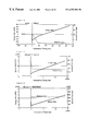
- FIG. 4 illustrates the relation between a command interval, savable electric energy dissipation, and a delay time, when the HDD makes a transition from an IDLE mode to an IDLE 2 mode;
- FIG. 5 illustrates the relation between a command interval, savable electric energy dissipation, and a delay time, when the HDD makes a transition from the IDLE 2 mode to an IDLE 3 mode;
- FIG. 6 illustrates the relation between a command interval, savable electric energy dissipation, and a delay time, when the HDD makes a transition from the IDLE 3 mode to a STANDBY mode;
- FIG. 7 illustrates a command interval distribution when a boot program in a certain operating system is executed
- FIG. 8 illustrates the relation between a time until the start of a transition to the IDLE 2 mode, savable electric energy dissipation, and a delay time, when weighting is performed by applying the command interval distribution of FIG. 7 as the time until the start of a transition to the IDLE 2 mode in FIG. 4;
- FIG. 9 illustrates the relation between a time until the start of a transition to the IDLE 3 mode, savable electric energy dissipation, and a delay time, when weighting is performed by applying the command interval distribution of FIG. 7 as the time until the start of a transition to the IDLE 3 mode in FIG. 5;
- FIG. 10 illustrates the relation between a time until the start of a transition to the STANDBY mode, savable electric energy dissipation, and a delay time, when weighting is performed by applying the command interval distribution of FIG. 7 as the time until the start of a transition to the STANDBY mode in FIG. 6;
- FIG. 11 illustrates a command interval distribution when one of the benchmark programs for comparing used battery hours is executed
- FIG. 12 illustrates savable power dissipation and a delay rate in the case where this distribution is applied to a transition to each power saving mode
- FIG. 13 illustrates savable power dissipation and a delay rate in the case where this distribution is applied to a transition to each power saving mode
- FIG. 14 illustrates savable power dissipation and a delay rate in the case where this distribution is applied to a transition to each power saving mode
- FIG. 15 illustrates a command interval distribution when one of the benchmark programs for comparing the execution performances of business application programs is executed
- FIG. 16 illustrates savable power dissipation and a delay rate in the case where this distribution is applied to a transition to each power saving mode
- FIG. 17 illustrates savable power dissipation and a delay rate in the case where this distribution is applied to a transition to power saving mode
- FIG. 18 illustrates savable power dissipation and a delay rate in the case where this distribution is applied to a transition to each power saving mode
- FIG. 19 illustrates a command interval distribution when another benchmark program for comparing used battery hours is executed
- FIG. 20 illustrates savable power dissipation and a delay rate in the case where this distribution is applied to a transition to each power saving mode
- FIG. 21 illustrates savable power dissipation and a delay rate in the case where this distribution is applied to a transition to each power saving mode
- FIG. 22 illustrates savable power dissipation and a delay rate in the case where this distribution is applied to a transition to each power saving mode
- FIG. 23 is a flowchart showing a method for computing a command interval distribution
- FIG. 24 is a flowchart showing the operation in the case where the HDD receives a command when operated
- FIG. 25 is a flowchart describing in detail the command receiving subroutine of FIG. 24;
- FIG. 26 is a flowchart describing in detail the command completing subroutine of FIG. 24;
- FIG. 27 is a flowchart describing in detail the FIG. 26 subroutine that determines when to enter a power saving mode
- FIG. 28 is a flowchart describing in detail the FIG. 26 subroutine that determines when to enter a power saving mode
- FIG. 29 is a flowchart describing in detail the FIG. 28 subroutine that computes saved energy
- FIG. 30 is a flowchart describing in detail the FIG. 28 subroutine that predicts the time that saved energy is maximized
- FIG. 31 is a flowchart describing in detail the FIG. 26 subroutine that reduces the influence of the past command access.
- FIG. 32 is a flowchart showing a timer interruption operation for making a transition to a power saving mode.
- FIG. 1 is a block diagram of a HDD to which the present invention is implemented.
- a disk unit 100 is constructed of a controller section 110 and a disk section 130 .
- the controller section 110 includes a host interface controller (HIC) 112 connected to a host computer 10 , a hard-disk controller (HDC) 114 connected to the HIC 112 to control the disk section, a channel 116 connected to the HDC 114 to control read and write signals, a microprocessor unit (MPU) 118 connected to the HIC 112 , HDC 114 , and channel 116 to control them, and a random access memory (RAM) 120 connected to the MPU 118 to store microcodes that are executed by the MPU 118 .
- HIC host interface controller
- HDC hard-disk controller
- MPU microprocessor unit
- RAM random access memory
- the disk section 130 is equipped with a motor 134 that spins a spindle 132 .
- Disks 136 A and 136 B are mounted on the spindle 132 so that they can rotate integrally with the spindle 132 . Although two disks are shown, one disk, or three or more disks may be provided.
- Read/write heads 138 A, 138 B, 138 C, and 138 D are respectively supported and arranged on the actuator arms 140 A, 140 B, 140 C, and 140 D so that they are opposed to the corresponding disk surfaces.
- the actuator arms 140 A through 140 D are attached to a voice coil motor (VCM) 144 via pivot shaft 142 , and with the rotation, the read/write heads 138 A through 138 D are moved to desired radial positions on the disks, respectively.
- VCM voice coil motor
- the motor 134 and VCM 144 are connected to the HDC 114 , and the number of rotations, speed, and the like can be controlled.
- the read/write heads 138 A through 138 D are connected to the channel 116 , and read and write signals are controlled by the channel 116 .
- FIG. 2 shows the transition of power dissipation between before and after a power saving mode.
- the horizontal axis represents time and the vertical axis represents power dissipation. Note that the diagram is simplified for explanation, and scales, waveforms, etc. are not accurate.
- the electric energy (power) dissipation corresponding to an area indicated as an oblique-line portion results in the loss of power for making a transition from the active mode to the power saving mode.
- the HDD completes a transition to the power saving mode at time t 3 and is in the power saving mode until it receives the next command at time t 4 .
- the HDD dissipates less power than the active mode, and the electric energy dissipation corresponding to an area indicated as a net-line portion (energy (EG)) results in the gain of power obtained by making a transition from the active mode to the power saving mode.
- the HDD performs an operation for returning to the active mode, such as an operation of loading the read/write head stand-by onto the disk again, in order to process the next command.
- the HDD dissipates more power than the active mode because of the return operation.
- the response to the command is delayed during the period, so that the electric energy dissipation corresponding to an area indicated as oblique-line portion EL 2 , which is the total power dissipation of the HDD during the delay time, results in the loss of power for returning from the power saving mode to the active mode.
- the HDD completes the return operation and starts processing the command.
- the electric energy dissipation (TEG) saved by making a transition to the power saving mode instead of remaining in the active mode is calculated by the following equation.
- TEG EG ⁇ ( EL 1 + EL 2 ) (1)
- EL 1 and EL 2 are constant. Therefore, if the EG obtained by making a transition to the power saving mode is less than EL 1 +EL 2 , the electric energy dissipation will become negative and therefore the HDD will dissipate more power than the case where no transition to the power saving mode is made. Therefore, in order to increase the electric energy dissipation to be saved, it is necessary that the HDD be in the power saving mode for more than a predetermined time.
- the electric power dissipation to be saved is zero and the delay time is also zero, in the case where the HDD receives the next command at a certain time within the period (indicated as A) before a transition to the power saving mode starts.
- a mechanism for controlling the HDD is generally constructed so that the HDD completely enters the power saving mode and then returns from that mode. For this reason, in the case where the HDD receives the next command during a transition to the power saving mode (i.e., during period B), the electric energy dissipation to be saved is calculated by the following equation.
- EL 3 is the time from reception of the next command to completion of the transition to the power saving mode, multiplied by the power dissipation in the active mode.
- the delay time of a response to a command is the sum of the time from reception of the next command to completion of a transition to the power saving mode and the time required to return from the power saving mode shown by b in FIG. 2 .
- the electric energy dissipation to be saved as described above is calculated by the following equation.
- the time in the power saving mode is short and EG is less than (EL 1 +EL 2 )
- more power is dissipated than in the case where there is no transition to the power saving mode.
- the delay time in this case is only the time taken to return from the power saving mode shown by b in FIG. 2 .
- the relation between the timing for receiving the next command, the electric energy dissipation TEG, and the delay time is obtained as shown by a graph of FIG. 3 . Assuming that the timing (time t 2 in FIG. 2) at which a transition to the power saving mode is started is zero, the timing before that is displayed as negative and the timing after that as positive.
- Equation (2) applied for savable electric energy dissipation.
- EL 3 decreases, while EL 1 and EL 2 are constant.
- the savable electric energy dissipation at time 0 assumes the minimum value (in this case, a negative number).
- the amount of savable electric energy dissipation increases linearly over time interval B.
- Equation (3) applies for the savable electric energy dissipation.
- EG increases, while EL 1 and EL 2 are constant.
- the savable electric energy dissipation increases linearly.
- the power gain EG obtained by entering the power saving mode, is balanced by the electric energy dissipation required for a transition to the power saving mode and a return from that mode.
- the amount of savable electric energy dissipation is zero. Thereafter, the savable electric energy dissipation goes to a positive value and increases linearly.
- TEG if the HDD receives the next command between the timing at which a transition to the power saving mode starts and time t c , TEG will go to a negative value and therefore more power will be dissipated than in the case where the HDD remains in the active mode.
- TEG if the HDD receives the next command after time t c , TEG will go to a positive value and therefore more power will be saved than in the case where the HDD remains in the active mode.
- the delay time between reception of the command and the start of the response is obtained as follows. That is, at time 0 , the sum of the times required for a transition to the power saving mode and a return from that mode is (a+b). Thus, the delay time is maximized as the next command is received immediately after the start of the transition. Thereafter, as the transition to the power saving mode advances, the remaining time of the time required for the transition decreases, and the delay time decreases in linearly. If the period equivalent to period B has elapsed, the delay time is only the time b required for a return to the active mode. Thus, at this time, the delay time is minimized.
- FIGS. 4, 5 , and 6 illustrate changes in TEG (indicated as “Energy Gain” in the figures) and a delay time (indicated as “Response Loss” in the figures) for four power saving modes.
- IDLE mode is a mode in which only track following operations are performed, no data read or write operations are performed.
- no track following operations by reading of a servo signal is performed and no power is supplied to the channel.
- motor resistance is further reduced unloading the read/write head from the disk onto a ramp outside the disk.
- STANDBY mode motor rotation is stopped. Therefore, power dissipation is reduced in an HDD at each of the following transitions IDLE mode to IDLE 2 mode, IDLE 2 mode to IDLE 3 mode, and IDLE 3 mode to STANDBY mode.
- FIG. 4 shows the relation between the command interval, the savable electric energy dissipation, and the delay time, when the HDD makes a transition from the IDLE mode to the IDLE 2 mode.
- the only operations that are performed are the electrical switching operation of reading a servo signal and the microscopic mechanical motion of the read/write head by the track following operation.
- the power dissipation by the mode transition is relatively low and the delay time is also relatively small.
- FIG. 5 shows the relation between the command interval, TEG, and the delay time, when the HDD makes a transition from the IDLE 2 mode to the IDLE 3 mode.
- the mechanical operation of unloading the read/write head from the disk to evacuate it to the ramp is performed.
- the power dissipation by the mode transition is relatively high and the delay time is also relatively great.
- FIG. 6 shows the relation between the command interval, TEG, and the delay time, when the HDD makes a transition from the IDLE 3 mode to the STANDBY mode.
- the operation of stopping or starting the motor is performed. Since such an operation requires a constant time, the power dissipation by the mode transition is relatively high and the delay time is also relatively great.
- the most power dissipation can be saved by predicting when the next command comes and then determining the time at which a transition to the power saving mode is started, in accordance with the timing. Also, it is necessary that the delay time at this time be in an allowable range.
- the prediction of when the next command comes is assumed based on information about the past command intervals.
- the next command interval can be predicted more accurately in a method of adopting a distribution of the past command intervals as the next command interval than in a method of adopting a mere average of the past command intervals as the next command interval.
- a plurality of times until the start of a transition to the power saving mode are selected.
- the graphs of FIGS. 4 through 6 are weighted by a command interval distribution, thereby computing the electric energy dissipation to be saved and the delay time of a response to the next command.
- the relation between the time until the start of a transition to the power saving mode, the electric energy dissipation to be saved, and the delay time of a response to the next command can be known.
- the time until the start of a transition, at which the electric energy dissipation to be saved is maximized and the delay time is sufficiently small, can be determined.
- FIGS. 7 through 22 illustrate examples of the operation of embodiments of the present invention.
- FIG. 7 shows a command interval distribution when a boot program in a certain operating system (OS) is executed.
- FIGS. 8 through 10 show the changes in TEG and a delay rate in the case where this distribution is applied to a transition to each power saving mode.
- FIG. 8 shows the relation between a time until the start of a transition to the IDLE 2 mode, savable power dissipation, and a delay rate, when weighting is performed by applying the command interval distribution of FIG. 7 as the time until the start of a transition to the IDLE 2 mode in FIG. 4 .
- FIG. 8 shows the relation between a time until the start of a transition to the IDLE 2 mode, savable power dissipation, and a delay rate, when weighting is performed by applying the command interval distribution of FIG. 7 as the time until the start of a transition to the IDLE 2 mode in FIG. 4 .
- FIG. 7 shows a
- the horizontal axis represents the time (displayed as “Transition Delay”) between the end of the previous command and the start of a transition to the power saving mode (in this case, IDLE 2 mode).
- the saved electric energy dissipation and the delay time are both divided by the time elapsed and are indicated as the saved power dissipation (displayed as “Power Gain”) and the delay rate (displayed as “Response Loss), respectively. From the graph of FIG. 8 it follows that the saved power dissipation is greatest when a transition to the IDLE 2 mode is started after about 100 ms since the previous command was completed. It also follows that the delay time is also sufficiently small after about 100 ms. Therefore, it is supposed that it is optimum to make a transition to the power saving mode after about 100 ms elapses since the previous command was completed.
- FIG. 9, as with FIG. 8, shows the relation between a time until the start of a transition to the IDLE 3 mode, savable power dissipation, and a delay rate, when weighting is performed by applying the command interval distribution of FIG. 7 as the time until the start of a transition to the IDLE 3 mode in FIG. 5 . From the graph of FIG. 9 it follows that there is no effect of saving power until about 6000 ms elapses since the previous command was completed. Therefore, at this time, it is supposed that it is good not to make a transition to the IDLE 3 mode.
- FIG. 10 shows the relation between a time until the start of a transition to the STANDBY mode, savable power dissipation, and a delay rate, when weighting is performed by applying the command interval distribution of FIG. 7 as the time until the start of a transition to the STANDBY mode in FIG. 6 . From the graph of FIG. 10 it follows that there is no effect of saving power until about 6000 ms elapses since the previous command was completed. Therefore, at this time, it is supposed that it is good not to make a transition to the STANDBY mode.
- FIGS. 11 through 14 show a command interval distribution when one of the benchmark programs for comparing used battery hours is executed (FIG. 11) and show changes in TEG and a delay time in the case where this distribution is applied to a transition to each power saving mode (FIGS. 12 through 14 ).
- the saved power dissipation is greatest when a transition to the IDLE 2 mode is started after about 100 ms since the previous command was completed.
- the delay time is sufficiently small after about 100 ms.
- FIG. 13 there is no effect of saving power until about 1500 ms elapses since the previous command was completed.
- the delay time is sufficiently small after about 2000 ms.
- FIG. 14 there is no effect of saving power until about 2000 ms elapses since the previous command was completed.
- the delay time is negligibly small after about 16000 ms.
- FIGS. 15 through 18 show a command interval distribution when one of the benchmark programs for comparing the execution performances of business application programs is executed (FIG. 15) and show changes in TEG and a delay time in the case where this distribution is applied to a transition to each power saving mode (FIGS. 16 through 18 ).
- the saved power dissipation is greatest when a transition to the IDLE 2 mode is started after about 200 ms since the previous command was completed. It is also understood that the delay time is sufficiently small after about 200 ms.
- FIG. 17 there is no effect of saving power until about 2000 ms elapses since the previous command was completed.
- the delay time is sufficiently small after about 2000 ms.
- FIG. 18 there is no effect of saving power until about 3000 ms elapses since the previous command was completed.
- the delay time is negligibly small after about 3000 ms.
- FIGS. 19 through 22 show a command interval distribution when another benchmark program for comparing the execution performances of business application programs is executed (FIG. 19) and show changes in TEG and a delay time in the case where this distribution is applied to a transition to each power saving mode (FIGS. 20 through 22 ).
- FIG. 20 the saved power dissipation is greatest when a transition to the IDLE 2 mode is started after about 1000 ms since the previous command was completed. It is also understood that the delay time is negligibly small through this period.
- FIG. 21 the saved power dissipation is greatest when a transition to the IDLE 3 mode is started between completion of the previous command and about 12000 ms. On the other hand, it is also understood that the delay time is negligibly small through this period.
- FIG. 22 the saved power dissipation is greatest when a transition to the IDLE 3 mode is started between completion of the previous command and about 4000 ms. On the other hand, it is also understood that the delay time is sufficiently small through this period.
- the foregoing description has analyzed which timing is effective in making a transition to the power saving mode, based on the past access pattern. Assuming the next command is received with the same distribution as the time distribution of the command intervals of the past access pattern, the analyzed effective timing also is effective for commands that will be received.
- the present invention determines timing at which a transition to the power saving mode is made, based on the past access pattern.
- the command intervals are divided into a plurality of time regions. At respective time regions, the data about the number of command intervals and an average time of the time region are held. In this manner, the total saved electric energy can be approximated by adding a saved electric energy dissipation calculated from the average time of each time region multiplied by the number of command intervals for all the time regions. The same also applies for the total delay time.
- the time between completion of the previous command and reception of the next command i.e., the time during which an interface is in an idle state
- a command interval the time between reception of the previous command and reception of the next command
- the time required for the HDD to process a command is also included in the command interval. That is, both the time during which the host computer does not send a command intentionally and the time during which the HDD processes a command and waits for the next command are processed without discrimination. Therefore, the conventional method is unsuitable for judging when the host computer sends the next command.
- Embodiments with a plurality of power saving modes also compute the saved power dissipation and a delay time when a transition is made from a shallow power saving mode to a deep power saving mode as described above.
- FIGS. 23 through 32 show methods of operation. By way of illustration these methods are described in the context of microcode for an HDD.
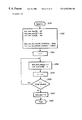
- FIG. 23 illustrates a flowchart of a method for computing a command interval distribution such as those shown in FIGS. 7, 11 , 15 , and 19 .
- an initialization program is started.
- time regions for command intervals are set.
- the number of time regions for command intervals is NUM_POINT. Note that in FIG. 23 the time intervals are given relative values and are therefore not limited to values directly displayed in a concrete unit such as a microsecond.
- the first time region is hist_min_time[0] and the time interval is set to a time more than 100 .
- the second time region is hist_min_time[1] and the time interval is set to a time more than 200.
- the third time region is hist_min_time[2] and the time interval is set to a time more than 300.
- the NUM_POINT-th time region is hist_min_time[NUM_POINT-1] and the time interval is set to a time more than 31500.
- the (NUM_POINT+1)st time region is hist_min_time[NUM_POINT] and the time interval is set to a time more than 60000. It is preferable that the time intervals be divided in a logarithmic manner, as in this example.
- step 2312 the process advances to step 2314 and an initial value of i is set to 0.
- step 2316 hist_total_time[i], which is the total number of the time intervals of commands in the time region, is initialized to 0, and hist_numcmd[i], which is the total number of commands in the time region, is initialized to 0.
- step 2318 the value of i is increased by 1.
- step 2320 if the value of i is less than NUM_POINT, the process returns to step 2316 again and steps 2316 through 2320 are repeated until the value of i is greater than NUM_POINT.
- step 2314 hist_total_time[i] and hist_numcmd[i] are initialized to 0 for all i's between 0 and NUM_POINT.
- step 2320 if the value of i is greater than NUM_POINT, the process advances to step 2322 and the total time of all the command intervals (total_time) is initialized to 0.
- step 2324 the initialization program ends.
- FIG. 24 illustrates a flowchart of an embodiment where an HDD receives a command when operated.
- a program for interrupting a power saving mode by a command is started.
- a subroutine for receiving a command shown in FIG. 25, is executed. If the HDD, which has completed the command receiving subroutine, receives the command from the host computer, in step 2414 it is judged whether or not the HDD is presently in the power saving mode. If the HDD is in the power saving mode, the process advances to step 2416 , in which the HDD returns from the power saving mode to the active mode. Then, the process advances to step 2418 .
- step 2414 if the HDD is not presently in the power saving mode, the process advances to step 2418 .
- step 2418 the command is processed.
- step 2420 a subroutine for completing a command, shown in FIG. 26, is executed.
- step 2422 the program for interrupting a power saving mode by a command is ended.
- FIG. 25 is a flowchart describing in detail the command receiving subroutine shown in step 2412 of FIG. 24 .
- step 2510 if the command receiving subroutine is started, in step 2512 the completion time (comp_time) of a command completed just before is subtracted from the incorporated timer of the MPU in the HDD. The difference is a command interval (interval).
- step 2514 the command interval (interval) is added to the total time. Let the sum is total_time.
- i is initialized to 0.
- step 2518 it is judged whether or not the command interval (interval) is less than the i th time region (hist_min_time[i]).
- step 2524 when it is judged that the command interval (interval) is less than the i th time region (hist_min_time[i]), the process advances to step 2524 .
- step 2518 when it is judged that the command interval (interval) is not less than the i th time region (hist min_time[i]), in step 2520 the value of i is increased by 1.
- step 2522 it is judged whether or not the value of i is less than the number of time regions for command intervals (NUM_POINT). When the value of i is less than the number of time regions for command intervals (NUM_POINT), the process returns to step 2518 again, in which it is judged whether or not the command interval belongs to the second smallest time interval.
- step 2522 when the value of i is not less than the number of time regions for command intervals (NUM_POINT), i.e., when the value of i is greater than the number of time regions for command intervals (NUM_POINT), the process advances to step 2524 .
- step 2524 it is judged whether or not the value of i equals 0.
- the value of i i.e., when in step 2518 the command interval (interval) is less than the i th time region (hist_min_time[i]), it means that the command interval is shorter than the minimum time until a transition to a power saving mode.
- step 2528 when the value of i does not equal 0, i.e., when the command interval (interval) belongs to the i th (where i g 1 ) time region (hist_min_time[i ⁇ 1]), the process advances to step 2526 and increases the total number of commands in the i th time region (hist_numcmd[i ⁇ 1]) by 1. Furthermore, the total number of the time intervals of commands in the i th time region (hist_total_time[i ⁇ 1]) is added with the corresponding command interval (interval). Let the sum is hist_total_time[i ⁇ 1]. In step 2528 , the subroutine ends.
- FIG. 26 is a flowchart describing in detail the command completing subroutine shown in step 2420 of FIG. 24 .
- Step 2610 determines whether the command completing subroutine has started. If so, in step 2612 the value of the incorporated timer of the MPU in the HDD at that point is set to the completion time of a command (comp_time). In step 2614 it is judged whether or not the total time (total_time) is greater than or equal to a value of MAX_TIME.
- the MAX_TIME here is a value twice the constant time described in (5), i.e., a value twice the interval during which the influence of the past command access is reduced.
- step 2614 when the total time (total_time) is greater than or equal to a value of MAX_TIME, the process advances to step 2616 .
- step 2616 a subroutine for reducing the influence of the past command access, which will be described later in FIG. 31, is executed and the process returns to step 2614 again.
- step 2618 when the total time (total_time) is less than a value of MAX_TIME, the process advances to step 2618 .
- step 2618 it is judged whether or not the command interval (interval) is greater than or equal to a value of the first time region (hist_min_time[0]).
- step 2620 When the command interval (interval) is greater than or equal to a value of the first time region (hist_min_time[0]), the process advances to step 2620 .
- step 2620 a subroutine for determining when to enter the power saving mode next, which will be described later in FIG. 27, is executed.
- step 2622 the subroutine ends.
- the command interval (interval) is less than a value of the first time region (hist_min_time[0])
- FIGS. 27 and 28 are flowcharts describing in detail the subroutine that determines when to enter the power saving mode next, shown in step 2620 of FIG. 26 .
- step 2710 if the subroutine for determining when to enter the power saving mode next is started then in step 2712 the value of i is initialized to 0.
- step 2714 it is judged whether or not the total number of commands in the (i+1) th time region (hist_numcmd[i]) equals 0.
- the process advances to step 2718 .
- step 2714 if hist_numcmd[i] is not equal to 0, the process advances to step 2716 .
- step 2716 the total number of the time intervals of commands in the (i+1) th time region (hist_total_time[i]) is divided by the total number of commands in the (i+1) th time region (hist_numcmd[i]). Let the quotient be hist_ave_time[i]. Therefore, hist_ave_time[i] represents an average command time interval per command in the (i+1) th time region. If the process ends step 2716 , it advances to step 2718 . In step 2718 the value of i is increased by 1.
- step 2720 it is judged whether or not the value of i is less than the number of time regions for command intervals (NUM_POINT). When the value of i is less than the number of time regions for command intervals (NUM_POINT), the process returns to step 2714 again. Until the value of i is greater than the number of time regions for command intervals (NUM_POINT), steps 2714 through 2720 are repeated. On the other hand, in step 2720 , when the value of i is not less than the number of time regions for command intervals (NUM_POINT), i.e., when the value of i is greater than the number of time regions for command intervals (NUM_POINT), the process advances to A, which is continued by A in FIG. 28 .
- step 2724 the value of the first time region (hist_total_time[i]) is stored in a variable (delay). Also, a value of energy_gain_sum, which is savable total energy (electric energy dissipation), and a value of resp_loss_sum, which is the total response delay with respect to commands, are initialized to 0, respectively.
- step 2726 the value of j is initialized to 0.
- step 2728 it is judged whether or not the total number of commands in the (j+1) th time region (hist_numcmd[j]) equals 0.
- step 2736 When the value of hist_numcmd[j] equals 0, i.e., when the total number of commands in the (j+1) th time region is 0, the process advances to step 2736 . In step 2736 the value of j is increased by 1. On the other hand, in step 2728 , if hist_numcmd[j] is not equal to 0, the process advances to step 2730 . In step 2730 , let an average command time interval per command in the (j+1) th time region be ave_interval. In step 2732 , a subroutine for computing saved energy, which will be described later in FIG. 29, is executed.
- step 2734 energy_gain is added to savable total energy (energy_gain_sum) and resp_loss is added to the total response delay with respect to commands (resp_loss_sum). Thereafter, the process advances to step 2736 and the value of j is increased by 1. In step 2738 it is judged whether or not the value of j is less than the number of time regions for command intervals (NUM_POINT). When the value of j is less than NUM_POINT, the process returns to step 2728 again. Until the value of j is greater than NUM_POINT, steps 2728 through 2738 are repeated.
- step 2738 when the value of j is greater than the number of time regions for command intervals (NUM_POINT), the process advances to step 2740 .
- step 2740 energy_gain_sum and resp_loss_sum are respectively divided by total_sum. With this, the savable power dissipation (power_gain[i]) and the response delay ratio (resp_loss_ratio[i]) are calculated.
- step 2742 the value of i is increased by 1.
- step 2744 it is judged whether or not the value of i is less than the number of time regions for command intervals (NUM_POINT). When the value of i is less than NUM_POINT, the process returns to step 2724 again.
- step 2744 when the value of i is greater than the number of time regions for command intervals (NUM_POINT), the process advances to step 2746 .
- step 2746 a subroutine is executed to predict the time when the amount of energy saved is maximized. Thereafter, the process advances to step 2748 and ends the subroutine.
- FIG. 29 is a flowchart describing in detail the subroutine that computes saved energy, shown in step 2732 of FIG. 28 .
- step 2910 if the subroutine for computing saved energy is started, in step 2912 it is judged whether or not the value of the ave_interval determined in step 2730 of FIG. 28 is less than the value of the delay determined in step 2724 of FIG. 28 .
- the value of the ave_interval is less than the value of the delay, an average command time interval per command is shorter than the time until a transition to a power saving mode.
- this case corresponds to the fact that in interval A in FIG.
- step 2914 sets the values of energy_gain and resp_loss to 0, and ends the subroutine at step 2922 .
- step 2912 when the value of ave_interval is not less than the value of delay, this case corresponds to the fact that in interval B or C in FIG. 2, the next command comes.
- step 2916 when the value of ave_interval is not less than the value of delay, this case corresponds to the fact that in interval B or C in FIG. 2, the next command comes.
- step 2916 when the value of ave_interval is not less than the value of delay, this case corresponds to the fact that in interval B or C in FIG. 2, the next command comes.
- step 2916 when the value of ave_interval is not less than the value of delay, this case corresponds to the fact that in interval B or C in FIG. 2, the next command comes.
- step 2916 when the value of ave_interval is not less than the value of delay, this case corresponds to the fact that in interval B or C in FIG. 2,
- step 2916 it is judged whether or not the value of ave_interval is less than the sum of the value of delay and TRANS_TIME that is the time required to enter a power saving mode.
- the value of ave_interval is less than delay+TRANS_TIME, this case corresponds to the fact that in interval B in FIG. 2, the next command comes.
- the process advances to step 2918 .
- energy_gain and resp_loss as described in FIG. 2, are calculated with equations.
- TRANS_ENERGY is the sum of the energy required for the HDD to enter a power saving mode and return from that mode, and is equivalent to EL 1 +EL 2 in FIG. 2 .
- BASE_POWER is the power dissipation of the HDD in an idle mode. Therefore, the second term on the right-hand side of Equation (4), (delay+TRANS_TIME) ⁇ ave_interval)*BASE_POWER, is equivalent to EL 3 of Equation (2).
- EXIT_TIME is the time required for the HDD to return from a power saving mode and is equivalent to the time b in FIG. 2 .
- TRANS_TIME is the time required for the HDD to enter a power saving mode and is equivalent to the time a in FIG. 2 .
- step 2918 After ending step 2918 , the process advances to step 2922 and ends the subroutine.
- step 2916 when the value of ave_interval is not less than delay+TRANS_TIME, this case corresponds to the fact that in interval C in FIG. 2, the next command comes.
- the process advances to step 2920 .
- step 2920 energy_gain and resp_loss, as described in FIG. 2, are calculated with equations.
- DELTA_POWER is the difference between the power dissipation of the HDD in an idle mode and the power dissipation of the HDD in a power saving mode. Therefore, the first term on the right-hand side of Equation (6), (ave_interval ⁇ (delay+TRANS_TIME)*DELTA_POWER, is equivalent to EG of Equation (3).
- FIG. 30 is a flowchart describing in detail the subroutine that predicts the time that saved energy is maximized, shown in step 2746 of FIG. 28 .
- step 3010 if the subroutine for predicting the time that saved energy is maximized is started, in step 3012 max_power_gain which is the maximum saved electric energy is initialized to 0 and max_power_num is initialized to NUM_POINT.
- step 3014 the value of i is initialized to 0 and the process advances to step 3016 .
- step 3016 it is judged whether or not the value of the response delay ratio (resp_loss_ratio[i]) is less than that of an allowable maximum average delay time (RESP_LOSS_CRITERIA).
- step 3018 it is judged whether or not power_gain[i] is greater that max_power_gain.
- step 3022 when the value of resp_loss_ratio[i] is not less than that of RESP_LOSS_CRITERIA, a response delay is not within an allowable range and the process advances step 3022 .
- step 3018 when power_gain[i] is greater that max_power_gain, the process advances to step 3020 .
- step 3020 the value of max_power_gain is updated to the value of power_gain[i], and the value of max_power_num is also updated to the value of i at that time. Thereafter, the process advances to step 3022 .
- step 3018 when power_gain[i] is not greater that max_power_gain, the values of max_power_gain and max_power_num are not updated and the process advances to step 3022 .
- step 3022 the value of i is increased by 1.
- step 3024 it is judged whether or not the value of i is less than NUM_POINT. When the value of i is less than NUM_POINT, the process returns to step 3016 again.
- step 3024 when the value of i is greater than NUM_POINT, in step 3026 the time until a transition to the next command (next_delay) is set to hist_min_time[max_power_num]. Thereafter, the process advances to step 3028 and ends the subroutine.
- FIG. 31 is a flowchart describing in detail the subroutine that reduces the influence of the past command access, shown in step 2616 of FIG. 26 .
- step 3110 if the subroutine for reducing the influence of the past command access is started, in step 3112 the value of i is initialized to 0.
- step 3114 the total number of the time intervals of commands in the (i+1)st time region (hist_total_time[i]) is divided by 2. Let the quotient be hist_total_time[i]. The total number of commands in the (i+1)st time region (hist_numcmd[i]) is divided by 2. Let the quotient be hist_numcmd[i].
- step 3116 the value of i is increased by 1.
- step 3118 it is judged whether or not the value of i is less than NUM_POINT. When the value of i is less than NUM_POINT, the process returns to step 3114 again. Until the value of i is greater than NUM_POINT, steps 3114 through 3118 are repeated. On the other hand, in step 3118 , when the value of i is greater than NUM_POINT, the process advances to step 3120 . In step 3120 , total_time is divided by 2. Let the quotient be total_time. Thereafter, the process advances to step 3122 and ends the subroutine.
- FIG. 32 is a flowchart showing a timer interruption operation for making a transition to a power saving mode.
- step 3210 if a timer interruption program for making a transition to a power saving mode is started, in step 3212 it is judged whether or not the HDD is presently processing a command. If it is processing a command, the program advances to step 3222 and ends. If it is not processing a command, the program advances to step 3214 . In step 3214 it is judged whether or not the HDD has presently entered a power saving mode. If it has already entered a power saving mode, the program advances to step 3222 and ends. If it has not entered a power saving mode yet, the program advances to step 3216 .
- step 3216 the completion time (comp_time) of a command completed just before is subtracted from the incorporated timer of the MPU in the HDD. Let the difference be elapsed_time.
- step 3218 it is judged whether or not the value of elapsed_time is greater than the time until a transition to the next power saving mode (next_delay).
- the program advances to step 3220 .
- the HDD enters the power saving mode and the program ends at step 3222 .
- step 3218 when the value of elapsed_time is not greater than the time until a transition to the next power saving mode (next_delay), the program advances to step 3222 and ends.
- Tables 1 and 2 show experimental results employing an actual HDD.
- Table 1 shows average power dissipations when the HDD executes one of the benchmark programs for comparing battery hours used, for a case without saving power (No Power Save), a case of employing ABLE 2 method, and a case of employing a new method of the present invention, respectively.
- the microcode controls three power saving modes, employing the ABLE 2 method. Even in the new method, three power saving modes are employed.
- the ABLE Mode in Table 1 is a parameter for controlling the deepest power saving mode that allows a transition. If this number is less, a power saving mode of a deeper level will be allowed.
- Table 2 shows scores (the higher, the better) when the HDD executes one of the benchmark programs for measuring HDD throughput, for the same cases as Table 1.
- the new method according to an embodiment of the present invention is about 9% less in the case of employing the deepest power saving mode than the ABLE 2 method.
- this embodiment is about 1% better than the ABLE 2 method and nearly equals the case of performing no power savings.
- the present invention further reduces the power dissipation of an HDD.
- the present invention further reduces the power dissipation of an HDD.
- a method and a system capable of computing the electric energy dissipation that is expected to be saved when a transition to a power saving mode is made, can be provided.
- the present invention can provide a method and a system that calculate the density of commands that an HDD receives from a host computer truly in accordance with the non-operating time of the HDD, while overcoming drawbacks of the prior art that, although the non-operating time of the HDD is short, the apparent density of commands received from the host computer is reduced and therefore a transition to a power saving mode is made at improper timing. While the present invention has been described with reference to a few specific embodiments, the description is illustrative of the invention and is not to be construed as limiting the invention. Various modifications may occur to those skilled in the art without departing from the true spirit and scope of the invention as defined by the appended claims.
Abstract
Description
| TABLE 1 | |||||
| Method | ABLE | Average | Ratio | ||
| No Power Save | N/A | 1796 mW | N/A | ||
| ABLE2 | 192 | 913 mW | 100.0% | ||
| 128 | 834 mW | 100.0% | |||
| 1 | 705 mW | 100.0% | |||
| New Method | 192 | 895 mW | 98.0% | ||
| 128 | 806 mW | 96.6% | |||
| 1 | 642 mW | 91.1% | |||
| TABLE 2 | |||||
| ABLE | Business | (vs | High End | (vs | |
| Method | Mode | Ratio | No PS) | Ratio | No PS) |
| No Power Save | N/A | 771 | 100.0% | 1,790 | 100.0% |
| ABLE2 | 192 | 754 | 97.8% | 1,770 | 98.9% |
| 128 | 756 | 98.1% | 1,770 | 98.9% | |
| 1 | 756 | 98.1% | 1,780 | 99.4% | |
| New Method | 192 | 771 | 100.0% | 1,770 | 98.9% |
| 128 | 771 | 100.0% | 1,790 | 100.0% | |
| 1 | 764 | 99.1% | 1,780 | 99.4% | |
Claims (2)
Applications Claiming Priority (2)
| Application Number | Priority Date | Filing Date | Title |
|---|---|---|---|
| JP10-337003 | 1998-11-27 | ||
| JP33700398A JP3819166B2 (en) | 1998-11-27 | 1998-11-27 | Energy consumption reduction method |
Publications (1)
| Publication Number | Publication Date |
|---|---|
| US6553501B1 true US6553501B1 (en) | 2003-04-22 |
Family
ID=18304575
Family Applications (1)
| Application Number | Title | Priority Date | Filing Date |
|---|---|---|---|
| US09/448,161 Expired - Fee Related US6553501B1 (en) | 1998-11-27 | 1999-11-24 | Predictive power saving method and apparatus for a device based on computed amount of power saving and time at which the device should transition from first state to second state |
Country Status (4)
| Country | Link |
|---|---|
| US (1) | US6553501B1 (en) |
| JP (1) | JP3819166B2 (en) |
| GB (1) | GB2347531B (en) |
| SG (1) | SG82037A1 (en) |
Cited By (48)
| Publication number | Priority date | Publication date | Assignee | Title |
|---|---|---|---|---|
| US20030014467A1 (en) * | 2001-07-12 | 2003-01-16 | Kiichiro Hanzawa | Multitasking operating system capable of reducing power consumption and vehicle electronic control unit using same |
| US20030084353A1 (en) * | 2001-10-31 | 2003-05-01 | Norman Chang | System and method for predictive power ramping |
| US20050181840A1 (en) * | 2004-02-17 | 2005-08-18 | Intel Corporation | Power management in communication devices |
| US20050251696A1 (en) * | 2002-09-09 | 2005-11-10 | Koninklijke Philips Electronics, N.V. | Method and apparatus for managing power consumption of a disk drive |
| US20050273638A1 (en) * | 2002-11-25 | 2005-12-08 | Fujitsu Limited | Power saving control system and power saving control method |
| US20060002220A1 (en) * | 2004-07-02 | 2006-01-05 | Seagate Technology Llc | Assessing energy requirements for a refreshed device |
| US20060015653A1 (en) * | 2004-07-19 | 2006-01-19 | Seagate Technology Llc | Expedited and low power command sequence servicing |
| US20060123259A1 (en) * | 2003-02-10 | 2006-06-08 | Sony Corporation | Information processing device and consumption power control method |
| US20060129703A1 (en) * | 2004-12-09 | 2006-06-15 | Hitachi Global Storage Technologies Netherlands B. V. | Data storage device and control method for power-save modes thereof |
| US20060156043A1 (en) * | 2005-01-13 | 2006-07-13 | Ying Liu | Dynamic power and clock-gating method and circuitry |
| US20060198225A1 (en) * | 2005-03-04 | 2006-09-07 | Seagate Technology Llc | Reducing power consumption in a data storage system |
| US7120806B1 (en) | 2001-10-31 | 2006-10-10 | Western Digital Technologies, Inc. | Method for setting a power operating mode transition interval of a disk drive in a mobile device based on application category |
| US20060265617A1 (en) * | 2005-05-18 | 2006-11-23 | Priborsky Anthony L | Power management in a system having multiple power modes |
| US20070053525A1 (en) * | 2005-09-06 | 2007-03-08 | Dell Products L.P. | System and method for reduction of information handling system power state transition of audible noise |
| US7334144B1 (en) * | 2003-06-05 | 2008-02-19 | Maxtor Corporation | Host-based power savings method and apparatus |
| US7380147B1 (en) | 2005-10-24 | 2008-05-27 | Western Digital Technologies, Inc. | Computer device employing a sliding window to set an idle mode timeout interval |
| US20080195877A1 (en) * | 2002-04-29 | 2008-08-14 | Apple Inc. | Conserving power by reducing voltage supplied to an instruction-processing portion of a processor |
| US20090031156A1 (en) * | 2006-02-09 | 2009-01-29 | Freescale Semiconductor, Inc. | Electronic Apparatus and Method of Conserving Energy |
| US20090145808A1 (en) * | 2007-11-30 | 2009-06-11 | Saudi Arabian Oil Company | Catalyst to attain low sulfur diesel |
| US20090235105A1 (en) * | 2008-03-11 | 2009-09-17 | Alexander Branover | Hardware Monitoring and Decision Making for Transitioning In and Out of Low-Power State |
| US20090235099A1 (en) * | 2008-03-11 | 2009-09-17 | Alexander Branover | Protocol for Transitioning In and Out of Zero-Power State |
| US20090235260A1 (en) * | 2008-03-11 | 2009-09-17 | Alexander Branover | Enhanced Control of CPU Parking and Thread Rescheduling for Maximizing the Benefits of Low-Power State |
| US20100058078A1 (en) * | 2008-08-27 | 2010-03-04 | Alexander Branover | Protocol for Power State Determination and Demotion |
| US20100070787A1 (en) * | 2008-09-18 | 2010-03-18 | International Business Machines Corporation | Power cap lower bound exploration in a server environment |
| US20100287422A1 (en) * | 2009-05-11 | 2010-11-11 | Fujitsu Limited | Transmission device and method for putting transmission device to sleep |
| US20100287394A1 (en) * | 2009-05-06 | 2010-11-11 | Alexander Branover | North-bridge to south-bridge protocol for placing processor in low power state |
| US20110112798A1 (en) * | 2009-11-06 | 2011-05-12 | Alexander Branover | Controlling performance/power by frequency control of the responding node |
| US20110268425A1 (en) * | 2010-04-29 | 2011-11-03 | Ati Technologies Ulc | Power management in multi-stream audio/video devices |
| US20120137113A1 (en) * | 2010-11-30 | 2012-05-31 | Inventec Corporation | Method of powering on server |
| US8255708B1 (en) * | 2007-08-10 | 2012-08-28 | Marvell International Ltd. | Apparatuses and methods for power saving in USB devices |
| US20120233480A1 (en) * | 2009-11-27 | 2012-09-13 | Nec Corporation | Power saving notification system, terminal device, power saving notification method, and power saving notification program |
| US8433937B1 (en) * | 2010-06-30 | 2013-04-30 | Western Digital Technologies, Inc. | Automated transitions power modes while continuously powering a power controller and powering down a media controller for at least one of the power modes |
| US8504854B2 (en) | 2010-06-21 | 2013-08-06 | Advanced Micro Devices, Inc. | Managing multiple operating points for stable virtual frequencies |
| US8862909B2 (en) | 2011-12-02 | 2014-10-14 | Advanced Micro Devices, Inc. | System and method for determining a power estimate for an I/O controller based on monitored activity levels and adjusting power limit of processing units by comparing the power estimate with an assigned power limit for the I/O controller |
| US8924758B2 (en) | 2011-12-13 | 2014-12-30 | Advanced Micro Devices, Inc. | Method for SOC performance and power optimization |
| US9001446B1 (en) | 2014-02-06 | 2015-04-07 | Lsi Corporation | System and method for power saving modes in multi-sensor magnetic recording |
| US9058834B1 (en) | 2013-11-08 | 2015-06-16 | Western Digital Technologies, Inc. | Power architecture for low power modes in storage devices |
| US9261949B2 (en) | 2010-10-29 | 2016-02-16 | Advanced Micro Devices, Inc. | Method for adaptive performance optimization of the soc |
| US9541988B2 (en) | 2014-09-22 | 2017-01-10 | Western Digital Technologies, Inc. | Data storage devices with performance-aware power capping |
| US20170099637A1 (en) * | 2012-03-23 | 2017-04-06 | Blackberry Limited | Methods and apparatus for controlling power consumption in an electronic device with a communication subsystem |
| US20170108915A1 (en) * | 2015-10-15 | 2017-04-20 | National Taiwan Normal University | Method of power management for saving energy |
| US9892058B2 (en) | 2015-12-16 | 2018-02-13 | Advanced Micro Devices, Inc. | Centrally managed unified shared virtual address space |
| US9965206B2 (en) | 2015-10-23 | 2018-05-08 | Western Digital Technologies, Inc. | Enhanced queue management for power control of data storage device |
| US10146293B2 (en) | 2014-09-22 | 2018-12-04 | Western Digital Technologies, Inc. | Performance-aware power capping control of data storage devices |
| US10592126B2 (en) * | 2017-11-07 | 2020-03-17 | Hefei Core Storage Electronic Limited | Memory management method, memory storage device and memory control circuit unit |
| US10970118B2 (en) | 2017-08-02 | 2021-04-06 | Advanced Micro Devices, Inc. | Shareable FPGA compute engine |
| US11422812B2 (en) | 2019-06-25 | 2022-08-23 | Advanced Micro Devices, Inc. | Method and apparatus for efficient programmable instructions in computer systems |
| US20230215107A1 (en) * | 2021-12-30 | 2023-07-06 | Snap Inc. | Enhanced reading with ar glasses |
Families Citing this family (17)
| Publication number | Priority date | Publication date | Assignee | Title |
|---|---|---|---|---|
| US6608729B1 (en) * | 1999-08-25 | 2003-08-19 | Seagate Technology Llc | Intelligent power management of disc drives |
| JP4841069B2 (en) * | 2001-07-24 | 2011-12-21 | パナソニック株式会社 | Storage device |
| JP4841070B2 (en) * | 2001-07-24 | 2011-12-21 | パナソニック株式会社 | Storage device |
| JP2003067262A (en) * | 2001-08-23 | 2003-03-07 | Mitsubishi Electric Corp | Data processing system |
| GB0123421D0 (en) | 2001-09-28 | 2001-11-21 | Memquest Ltd | Power management system |
| KR100597733B1 (en) | 2002-01-03 | 2006-07-07 | 삼성전자주식회사 | Computer system and booting method thereof |
| JP4921169B2 (en) * | 2003-09-18 | 2012-04-25 | コーニンクレッカ フィリップス エレクトロニクス エヌ ヴィ | Motor power controller for disk drive, disk drive having motor power controller and method for controlling motor power of disk drive |
| US7634615B2 (en) * | 2004-06-10 | 2009-12-15 | Marvell World Trade Ltd. | Adaptive storage system |
| JP4749793B2 (en) * | 2004-08-05 | 2011-08-17 | パナソニック株式会社 | Power saving processing apparatus, power saving processing method, and power saving processing program |
| JP2006099665A (en) | 2004-09-30 | 2006-04-13 | Hitachi Global Storage Technologies Netherlands Bv | Data storage device, and control method of power save mode of serial interface part thereof |
| JP4578396B2 (en) * | 2005-12-08 | 2010-11-10 | 株式会社日立超エル・エス・アイ・システムズ | Information processing device |
| JP4961275B2 (en) * | 2007-06-15 | 2012-06-27 | 株式会社日立製作所 | Storage device and disk device rotation speed control method |
| JP5288331B2 (en) * | 2009-02-05 | 2013-09-11 | 日本電気株式会社 | I / O instruction failure recovery circuit, I / O instruction failure recovery method, and I / O instruction failure recovery program |
| JP2011108045A (en) * | 2009-11-18 | 2011-06-02 | Hitachi Ltd | Computer system, management server and power reduction method |
| US8976405B2 (en) * | 2010-12-20 | 2015-03-10 | Canon Kabushiki Kaisha | Printing apparatus and control method therefor |
| US8862906B2 (en) * | 2011-04-01 | 2014-10-14 | Intel Corporation | Control of platform power consumption using coordination of platform power management and display power management |
| US9177534B2 (en) | 2013-03-15 | 2015-11-03 | Intel Corporation | Data transmission for display partial update |
Citations (15)
| Publication number | Priority date | Publication date | Assignee | Title |
|---|---|---|---|---|
| JPS60171672A (en) | 1984-02-15 | 1985-09-05 | Ricoh Co Ltd | Disk recorder |
| JPH0349660A (en) | 1989-07-17 | 1991-03-04 | Kibun Kk | Devil's tongue-containing sauce |
| JPH046665A (en) | 1990-04-25 | 1992-01-10 | Mitsubishi Electric Corp | Recording disk |
| JPH0411353A (en) | 1990-04-27 | 1992-01-16 | Matsushita Electric Ind Co Ltd | Magnetic disk device |
| JPH0423269A (en) | 1990-05-18 | 1992-01-27 | Toshiba Corp | Disk device |
| JPH0492254A (en) | 1990-08-08 | 1992-03-25 | Hitachi Ltd | Hard disk memory device |
| JPH04123359A (en) | 1990-09-14 | 1992-04-23 | Mitsubishi Electric Corp | Optical disk device |
| JPH04205963A (en) | 1990-11-30 | 1992-07-28 | Fujitsu Ltd | Disk device |
| JPH05217272A (en) | 1992-01-31 | 1993-08-27 | Hitachi Ltd | Disk recording and/or reproducing device |
| JPH0696517A (en) | 1992-09-11 | 1994-04-08 | Matsushita Electric Ind Co Ltd | Magnetic disk apparatus |
| JPH07210975A (en) | 1993-12-30 | 1995-08-11 | Internatl Business Mach Corp <Ibm> | Method and equipment for controlling power consumption |
| JPH07334913A (en) | 1994-06-03 | 1995-12-22 | Internatl Business Mach Corp <Ibm> | Method and equipment for reducing power consumption of disk-drive for computer |
| US5481733A (en) * | 1994-06-15 | 1996-01-02 | Panasonic Technologies, Inc. | Method for managing the power distributed to a disk drive in a laptop computer |
| EP0737909A2 (en) | 1995-04-13 | 1996-10-16 | International Business Machines Corporation | Disk drive power management system and method |
| EP0751512A2 (en) | 1995-06-30 | 1997-01-02 | International Business Machines Corporation | Disk drive with adaptive demand-driven power management |
Family Cites Families (2)
| Publication number | Priority date | Publication date | Assignee | Title |
|---|---|---|---|---|
| DE3732370A1 (en) * | 1987-09-25 | 1989-04-06 | Hoechst Ag | METHOD FOR MIXING LIVING CELLS OR MICROORGANISMS WITH A VISCOSE LIQUID, AND MIXTURES PRODUCED BY THIS METHOD |
| JPH0349660U (en) * | 1989-09-18 | 1991-05-15 |
-
1998
- 1998-11-27 JP JP33700398A patent/JP3819166B2/en not_active Expired - Lifetime
-
1999
- 1999-11-16 SG SG9905762A patent/SG82037A1/en unknown
- 1999-11-24 US US09/448,161 patent/US6553501B1/en not_active Expired - Fee Related
- 1999-11-24 GB GB9927647A patent/GB2347531B/en not_active Expired - Fee Related
Patent Citations (21)
| Publication number | Priority date | Publication date | Assignee | Title |
|---|---|---|---|---|
| JPS60171672A (en) | 1984-02-15 | 1985-09-05 | Ricoh Co Ltd | Disk recorder |
| JPH0349660A (en) | 1989-07-17 | 1991-03-04 | Kibun Kk | Devil's tongue-containing sauce |
| JPH046665A (en) | 1990-04-25 | 1992-01-10 | Mitsubishi Electric Corp | Recording disk |
| JPH0411353A (en) | 1990-04-27 | 1992-01-16 | Matsushita Electric Ind Co Ltd | Magnetic disk device |
| JPH0423269A (en) | 1990-05-18 | 1992-01-27 | Toshiba Corp | Disk device |
| JPH0492254A (en) | 1990-08-08 | 1992-03-25 | Hitachi Ltd | Hard disk memory device |
| JPH04123359A (en) | 1990-09-14 | 1992-04-23 | Mitsubishi Electric Corp | Optical disk device |
| JPH04205963A (en) | 1990-11-30 | 1992-07-28 | Fujitsu Ltd | Disk device |
| JPH05217272A (en) | 1992-01-31 | 1993-08-27 | Hitachi Ltd | Disk recording and/or reproducing device |
| JPH0696517A (en) | 1992-09-11 | 1994-04-08 | Matsushita Electric Ind Co Ltd | Magnetic disk apparatus |
| JPH07210975A (en) | 1993-12-30 | 1995-08-11 | Internatl Business Mach Corp <Ibm> | Method and equipment for controlling power consumption |
| US5452277A (en) | 1993-12-30 | 1995-09-19 | International Business Machines Corporation | Adaptive system for optimizing disk drive power consumption |
| JPH07334913A (en) | 1994-06-03 | 1995-12-22 | Internatl Business Mach Corp <Ibm> | Method and equipment for reducing power consumption of disk-drive for computer |
| US5481733A (en) * | 1994-06-15 | 1996-01-02 | Panasonic Technologies, Inc. | Method for managing the power distributed to a disk drive in a laptop computer |
| US5493670A (en) | 1994-06-15 | 1996-02-20 | Panasonic Technologies, Inc. | Adaptive disk spin-down method for managing the power distributed to a disk drive in a laptop computer |
| JPH0887383A (en) | 1994-06-15 | 1996-04-02 | Matsushita Electric Ind Co Ltd | Power saving method for computer with disk |
| EP0737909A2 (en) | 1995-04-13 | 1996-10-16 | International Business Machines Corporation | Disk drive power management system and method |
| JPH08287583A (en) | 1995-04-13 | 1996-11-01 | Internatl Business Mach Corp <Ibm> | System and method for electric power management of disk driving device |
| US5774292A (en) * | 1995-04-13 | 1998-06-30 | International Business Machines Corporation | Disk drive power management system and method |
| EP0751512A2 (en) | 1995-06-30 | 1997-01-02 | International Business Machines Corporation | Disk drive with adaptive demand-driven power management |
| JPH0917099A (en) | 1995-06-30 | 1997-01-17 | Internatl Business Mach Corp <Ibm> | Method for control of power consumption in data recording disk drive |
Non-Patent Citations (1)
| Title |
|---|
| IBM TDB; Power Savings Using Predictive Usage Methods; Jul., 1998; IBM Corporation; IBM RD v41 n411 07-98 article 411130 Order: 98A 60476. * |
Cited By (78)
| Publication number | Priority date | Publication date | Assignee | Title |
|---|---|---|---|---|
| US7386853B2 (en) * | 2001-07-12 | 2008-06-10 | Denso Corporation | Multitasking operating system capable of reducing power consumption and vehicle electronic control unit using same |
| US20030014467A1 (en) * | 2001-07-12 | 2003-01-16 | Kiichiro Hanzawa | Multitasking operating system capable of reducing power consumption and vehicle electronic control unit using same |
| US7120806B1 (en) | 2001-10-31 | 2006-10-10 | Western Digital Technologies, Inc. | Method for setting a power operating mode transition interval of a disk drive in a mobile device based on application category |
| US20030084353A1 (en) * | 2001-10-31 | 2003-05-01 | Norman Chang | System and method for predictive power ramping |
| US20080195877A1 (en) * | 2002-04-29 | 2008-08-14 | Apple Inc. | Conserving power by reducing voltage supplied to an instruction-processing portion of a processor |
| US8166324B2 (en) * | 2002-04-29 | 2012-04-24 | Apple Inc. | Conserving power by reducing voltage supplied to an instruction-processing portion of a processor |
| US7075744B2 (en) * | 2002-09-09 | 2006-07-11 | Koninklijke Philips Electronics N.V. | Method and apparatus for managing power consumption of a disk drive |
| US20050251696A1 (en) * | 2002-09-09 | 2005-11-10 | Koninklijke Philips Electronics, N.V. | Method and apparatus for managing power consumption of a disk drive |
| US7275166B2 (en) * | 2002-11-25 | 2007-09-25 | Fujitsu Limited | Power saving control system and power saving control method |
| US20050273638A1 (en) * | 2002-11-25 | 2005-12-08 | Fujitsu Limited | Power saving control system and power saving control method |
| US20060123259A1 (en) * | 2003-02-10 | 2006-06-08 | Sony Corporation | Information processing device and consumption power control method |
| US7412615B2 (en) | 2003-02-10 | 2008-08-12 | Sony Corporation | Information processing equipment and power consumption control method |
| US7334144B1 (en) * | 2003-06-05 | 2008-02-19 | Maxtor Corporation | Host-based power savings method and apparatus |
| USRE43211E1 (en) * | 2003-06-05 | 2012-02-21 | Seagate Technology Llc | Host-based power savings method and apparatus |
| US20050181840A1 (en) * | 2004-02-17 | 2005-08-18 | Intel Corporation | Power management in communication devices |
| US7281144B2 (en) * | 2004-02-17 | 2007-10-09 | Intel Corporation | Power management in communication devices |
| US7321521B2 (en) | 2004-07-02 | 2008-01-22 | Seagate Technology Llc | Assessing energy requirements for a refreshed device |
| USRE44009E1 (en) | 2004-07-02 | 2013-02-19 | Seagate Technology Llc | Assessing energy requirements for a refreshed device |
| US20060002220A1 (en) * | 2004-07-02 | 2006-01-05 | Seagate Technology Llc | Assessing energy requirements for a refreshed device |
| US7904604B2 (en) | 2004-07-19 | 2011-03-08 | Seagate Technology Llc | Expedited and low power command sequence servicing |
| US20060015653A1 (en) * | 2004-07-19 | 2006-01-19 | Seagate Technology Llc | Expedited and low power command sequence servicing |
| US20060129703A1 (en) * | 2004-12-09 | 2006-06-15 | Hitachi Global Storage Technologies Netherlands B. V. | Data storage device and control method for power-save modes thereof |
| US7487374B2 (en) * | 2005-01-13 | 2009-02-03 | International Business Machines Corporation | Dynamic power and clock-gating method and circuitry with sleep mode based on estimated time for receipt of next wake-up signal |
| US20060156043A1 (en) * | 2005-01-13 | 2006-07-13 | Ying Liu | Dynamic power and clock-gating method and circuitry |
| US20060198225A1 (en) * | 2005-03-04 | 2006-09-07 | Seagate Technology Llc | Reducing power consumption in a data storage system |
| US7177222B2 (en) | 2005-03-04 | 2007-02-13 | Seagate Technology Llc | Reducing power consumption in a data storage system |
| US20060265617A1 (en) * | 2005-05-18 | 2006-11-23 | Priborsky Anthony L | Power management in a system having multiple power modes |
| US7747878B2 (en) * | 2005-09-06 | 2010-06-29 | Dell Products L.P. | System and method for reduction of information handling system power state transition of audible noise |
| US20070053525A1 (en) * | 2005-09-06 | 2007-03-08 | Dell Products L.P. | System and method for reduction of information handling system power state transition of audible noise |
| US7380147B1 (en) | 2005-10-24 | 2008-05-27 | Western Digital Technologies, Inc. | Computer device employing a sliding window to set an idle mode timeout interval |
| US8181051B2 (en) * | 2006-02-09 | 2012-05-15 | Freescale Semiconductor, Inc. | Electronic apparatus and method of conserving energy |
| US20090031156A1 (en) * | 2006-02-09 | 2009-01-29 | Freescale Semiconductor, Inc. | Electronic Apparatus and Method of Conserving Energy |
| US8762748B1 (en) | 2007-08-10 | 2014-06-24 | Marvell International Ltd. | Apparatus and methods for power saving in USB devices |
| US9625976B1 (en) | 2007-08-10 | 2017-04-18 | Marvell International Ltd. | Apparatus and methods for power saving in USB devices |
| US8255708B1 (en) * | 2007-08-10 | 2012-08-28 | Marvell International Ltd. | Apparatuses and methods for power saving in USB devices |
| US20090145808A1 (en) * | 2007-11-30 | 2009-06-11 | Saudi Arabian Oil Company | Catalyst to attain low sulfur diesel |
| US20090235260A1 (en) * | 2008-03-11 | 2009-09-17 | Alexander Branover | Enhanced Control of CPU Parking and Thread Rescheduling for Maximizing the Benefits of Low-Power State |
| US20090235099A1 (en) * | 2008-03-11 | 2009-09-17 | Alexander Branover | Protocol for Transitioning In and Out of Zero-Power State |
| US20090235105A1 (en) * | 2008-03-11 | 2009-09-17 | Alexander Branover | Hardware Monitoring and Decision Making for Transitioning In and Out of Low-Power State |
| US8028185B2 (en) | 2008-03-11 | 2011-09-27 | Globalfoundries Inc. | Protocol for transitioning in and out of zero-power state |
| US8112648B2 (en) | 2008-03-11 | 2012-02-07 | Globalfoundries Inc. | Enhanced control of CPU parking and thread rescheduling for maximizing the benefits of low-power state |
| US8156362B2 (en) | 2008-03-11 | 2012-04-10 | Globalfoundries Inc. | Hardware monitoring and decision making for transitioning in and out of low-power state |
| US20100058078A1 (en) * | 2008-08-27 | 2010-03-04 | Alexander Branover | Protocol for Power State Determination and Demotion |
| US8112647B2 (en) | 2008-08-27 | 2012-02-07 | Globalfoundries Inc. | Protocol for power state determination and demotion |
| US8028183B2 (en) * | 2008-09-18 | 2011-09-27 | International Business Machines Corporation | Power cap lower bound exploration in a server environment |
| US20100070787A1 (en) * | 2008-09-18 | 2010-03-18 | International Business Machines Corporation | Power cap lower bound exploration in a server environment |
| US20100287394A1 (en) * | 2009-05-06 | 2010-11-11 | Alexander Branover | North-bridge to south-bridge protocol for placing processor in low power state |
| US8566628B2 (en) | 2009-05-06 | 2013-10-22 | Advanced Micro Devices, Inc. | North-bridge to south-bridge protocol for placing processor in low power state |
| US20100287422A1 (en) * | 2009-05-11 | 2010-11-11 | Fujitsu Limited | Transmission device and method for putting transmission device to sleep |
| US8516282B2 (en) * | 2009-05-11 | 2013-08-20 | Fujitsu Limited | Transmission device and method for putting transmission device to sleep |
| US9021209B2 (en) | 2009-11-06 | 2015-04-28 | Advanced Micro Devices, Inc. | Cache flush based on idle prediction and probe activity level |
| US20110112798A1 (en) * | 2009-11-06 | 2011-05-12 | Alexander Branover | Controlling performance/power by frequency control of the responding node |
| US20110113202A1 (en) * | 2009-11-06 | 2011-05-12 | Alexander Branover | Cache flush based on idle prediction and probe activity level |
| US20120233480A1 (en) * | 2009-11-27 | 2012-09-13 | Nec Corporation | Power saving notification system, terminal device, power saving notification method, and power saving notification program |
| US20110268425A1 (en) * | 2010-04-29 | 2011-11-03 | Ati Technologies Ulc | Power management in multi-stream audio/video devices |
| US9325929B2 (en) * | 2010-04-29 | 2016-04-26 | Ati Technologies Ulc | Power management in multi-stream audio/video devices |
| US8504854B2 (en) | 2010-06-21 | 2013-08-06 | Advanced Micro Devices, Inc. | Managing multiple operating points for stable virtual frequencies |
| US8433937B1 (en) * | 2010-06-30 | 2013-04-30 | Western Digital Technologies, Inc. | Automated transitions power modes while continuously powering a power controller and powering down a media controller for at least one of the power modes |
| US9261949B2 (en) | 2010-10-29 | 2016-02-16 | Advanced Micro Devices, Inc. | Method for adaptive performance optimization of the soc |
| US8667202B2 (en) * | 2010-11-30 | 2014-03-04 | Inventec Corporation | Method of powering on HDD modules via connectors in server |
| US20120137113A1 (en) * | 2010-11-30 | 2012-05-31 | Inventec Corporation | Method of powering on server |
| US8862909B2 (en) | 2011-12-02 | 2014-10-14 | Advanced Micro Devices, Inc. | System and method for determining a power estimate for an I/O controller based on monitored activity levels and adjusting power limit of processing units by comparing the power estimate with an assigned power limit for the I/O controller |
| US8924758B2 (en) | 2011-12-13 | 2014-12-30 | Advanced Micro Devices, Inc. | Method for SOC performance and power optimization |
| US20170099637A1 (en) * | 2012-03-23 | 2017-04-06 | Blackberry Limited | Methods and apparatus for controlling power consumption in an electronic device with a communication subsystem |
| US10225801B2 (en) * | 2012-03-23 | 2019-03-05 | 2236008 Ontario Inc. | Methods and apparatus for controlling power consumption in an electronic device with a communication subsystem |
| US9058834B1 (en) | 2013-11-08 | 2015-06-16 | Western Digital Technologies, Inc. | Power architecture for low power modes in storage devices |
| US9001446B1 (en) | 2014-02-06 | 2015-04-07 | Lsi Corporation | System and method for power saving modes in multi-sensor magnetic recording |
| US9541988B2 (en) | 2014-09-22 | 2017-01-10 | Western Digital Technologies, Inc. | Data storage devices with performance-aware power capping |
| US10146293B2 (en) | 2014-09-22 | 2018-12-04 | Western Digital Technologies, Inc. | Performance-aware power capping control of data storage devices |
| US20170108915A1 (en) * | 2015-10-15 | 2017-04-20 | National Taiwan Normal University | Method of power management for saving energy |
| US10019050B2 (en) * | 2015-10-15 | 2018-07-10 | National Taiwan Normal University | Method of power management for saving energy |
| US9965206B2 (en) | 2015-10-23 | 2018-05-08 | Western Digital Technologies, Inc. | Enhanced queue management for power control of data storage device |
| US9892058B2 (en) | 2015-12-16 | 2018-02-13 | Advanced Micro Devices, Inc. | Centrally managed unified shared virtual address space |
| US10970118B2 (en) | 2017-08-02 | 2021-04-06 | Advanced Micro Devices, Inc. | Shareable FPGA compute engine |
| US10592126B2 (en) * | 2017-11-07 | 2020-03-17 | Hefei Core Storage Electronic Limited | Memory management method, memory storage device and memory control circuit unit |
| US11422812B2 (en) | 2019-06-25 | 2022-08-23 | Advanced Micro Devices, Inc. | Method and apparatus for efficient programmable instructions in computer systems |
| US20230215107A1 (en) * | 2021-12-30 | 2023-07-06 | Snap Inc. | Enhanced reading with ar glasses |
| US11861801B2 (en) * | 2021-12-30 | 2024-01-02 | Snap Inc. | Enhanced reading with AR glasses |
Also Published As
| Publication number | Publication date |
|---|---|
| JP3819166B2 (en) | 2006-09-06 |
| GB9927647D0 (en) | 2000-01-19 |
| SG82037A1 (en) | 2001-07-24 |
| GB2347531B (en) | 2003-07-30 |
| GB2347531A (en) | 2000-09-06 |
| JP2000173152A (en) | 2000-06-23 |
Similar Documents
| Publication | Publication Date | Title |
|---|---|---|
| US6553501B1 (en) | Predictive power saving method and apparatus for a device based on computed amount of power saving and time at which the device should transition from first state to second state | |
| JP2557202B2 (en) | Power consumption management method and apparatus | |
| US6608729B1 (en) | Intelligent power management of disc drives | |
| US5345347A (en) | Disk drive with reduced power modes | |
| EP0751512B1 (en) | Disk drive with adaptive demand-driven power management | |
| US6735037B1 (en) | High reliability storage drive and data write method | |
| US7380147B1 (en) | Computer device employing a sliding window to set an idle mode timeout interval | |
| US5493670A (en) | Adaptive disk spin-down method for managing the power distributed to a disk drive in a laptop computer | |
| US8327177B2 (en) | System and method for information handling system storage device power consumption management | |
| US7010653B2 (en) | Data storage device, command queue re-ordering method, and data processing method and program | |
| US8245064B2 (en) | Power conservation during a power mode transition | |
| KR100288291B1 (en) | Method for searching adaptive sector for reducing power consumption of disc drive | |
| EP1730622B1 (en) | Power saving methode and system | |
| US20050125602A1 (en) | HDD with storage of critical data in FLASH | |
| US8046595B2 (en) | Method of controlling operating clock frequency of hard disk drive, recording medium, and hard disk drive | |
| US6751741B1 (en) | Computer power management apparatus and method for optimizing CPU throttling | |
| US20020109935A1 (en) | Thermal performance of an integrated amplifier in a disc drive | |
| US7174421B2 (en) | HDD with rapid availability of critical data after critical event | |
| US20050125603A1 (en) | Method for rapid availability of critical data through re-allocation | |
| US6134069A (en) | Method of power saving in a disk drive apparatus with head unloading and spin reduction | |
| JP2000228053A (en) | Method and device for controlling disk drive | |
| US20010026416A1 (en) | Magnetic storage and head unload controlling method of magnetic storage | |
| US7602570B2 (en) | Motor power controller for a disk drive, disk drive comprising a motor power controller and method for controlling the motor power of a disk drive | |
| US20050125651A1 (en) | Method for providing critical data in an HDD after critical event | |
| JP2016201160A (en) | Information processor, method for controlling information processor, and program |
Legal Events
| Date | Code | Title | Description |
|---|---|---|---|
| AS | Assignment |
Owner name: INTERNATIONAL BUSINESS MACHINES CORPORATION, NEW Y Free format text: ASSIGNMENT OF ASSIGNORS INTEREST;ASSIGNOR:YOKOE, YUJI;REEL/FRAME:010418/0826 Effective date: 19991119 |
|
| FEPP | Fee payment procedure |
Free format text: PAYOR NUMBER ASSIGNED (ORIGINAL EVENT CODE: ASPN); ENTITY STATUS OF PATENT OWNER: LARGE ENTITY |
|
| AS | Assignment |
Owner name: HITACHI GLOBAL STORAGE TECHNOLOGIES NETHERLANDS B. Free format text: CHANGE OF NAME;ASSIGNOR:MARIANA HDD B.V.;REEL/FRAME:015348/0191 Effective date: 20021231 Owner name: MARIANA HDD B.V., NETHERLANDS Free format text: ASSIGNMENT OF ASSIGNORS INTEREST;ASSIGNOR:INTERNATIONAL BUSINESS MACHINES CORPORATION;REEL/FRAME:015370/0450 Effective date: 20021231 |
|
| FEPP | Fee payment procedure |
Free format text: PAYER NUMBER DE-ASSIGNED (ORIGINAL EVENT CODE: RMPN); ENTITY STATUS OF PATENT OWNER: LARGE ENTITY Free format text: PAYOR NUMBER ASSIGNED (ORIGINAL EVENT CODE: ASPN); ENTITY STATUS OF PATENT OWNER: LARGE ENTITY |
|
| FPAY | Fee payment |
Year of fee payment: 4 |
|
| FPAY | Fee payment |
Year of fee payment: 8 |
|
| AS | Assignment |
Owner name: HGST, NETHERLANDS B.V., NETHERLANDS Free format text: CHANGE OF NAME;ASSIGNOR:HGST, NETHERLANDS B.V.;REEL/FRAME:029341/0777 Effective date: 20120723 Owner name: HGST NETHERLANDS B.V., NETHERLANDS Free format text: CHANGE OF NAME;ASSIGNOR:HITACHI GLOBAL STORAGE TECHNOLOGIES NETHERLANDS B.V.;REEL/FRAME:029341/0777 Effective date: 20120723 |
|
| REMI | Maintenance fee reminder mailed | ||
| LAPS | Lapse for failure to pay maintenance fees | ||
| STCH | Information on status: patent discontinuation |
Free format text: PATENT EXPIRED DUE TO NONPAYMENT OF MAINTENANCE FEES UNDER 37 CFR 1.362 |
|
| FP | Lapsed due to failure to pay maintenance fee |
Effective date: 20150422 |
|
| AS | Assignment |
Owner name: WESTERN DIGITAL TECHNOLOGIES, INC., CALIFORNIA Free format text: ASSIGNMENT OF ASSIGNORS INTEREST;ASSIGNOR:HGST NETHERLANDS B.V.;REEL/FRAME:040818/0551 Effective date: 20160831 |