US6574363B1 - Method for color detection in video images - Google Patents
Method for color detection in video images Download PDFInfo
- Publication number
- US6574363B1 US6574363B1 US09/438,405 US43840599A US6574363B1 US 6574363 B1 US6574363 B1 US 6574363B1 US 43840599 A US43840599 A US 43840599A US 6574363 B1 US6574363 B1 US 6574363B1
- Authority
- US
- United States
- Prior art keywords
- signal
- axis
- color
- interest
- region
- Prior art date
- Legal status (The legal status is an assumption and is not a legal conclusion. Google has not performed a legal analysis and makes no representation as to the accuracy of the status listed.)
- Expired - Lifetime
Links
Images


Classifications
-
- H—ELECTRICITY
- H04—ELECTRIC COMMUNICATION TECHNIQUE
- H04N—PICTORIAL COMMUNICATION, e.g. TELEVISION
- H04N9/00—Details of colour television systems
- H04N9/64—Circuits for processing colour signals
- H04N9/643—Hue control means, e.g. flesh tone control
Definitions
- the present invention relates to a method and apparatus for detecting color in video images, and in particular to a method and apparatus for identifying pixels of a given color in a field of YUV video.
- a variety of discrimination systems operating in a range of circumstances, use color analysis as a basic tool.
- An example can be found in agriculture where a green area, such as a weed or other target plant, must be detected in an area of another color, such as brown soil, in order to be sprayed.
- PCT/CA95/00595 discloses a spray controller comprising a detector that generates red, green and blue color signals across a field of view. The color signals are used to generate an output control signal ‘its green’ or ‘not green’ for actuating a spray nozzle on detection of something deemed to be green.
- Two possible algorithms which determine if something is ‘green’ rather than ‘not green’ are described. One requires the level of green to exceed each of the red and blue components in the color signal. The second algorithm requires the green level to exceed the red level and the blue level to be less than a set value.
- the bandwidth of the chroma signal in a standard video signal is sufficient only for determining the chrominance accurately over a span of approximately nine pixels horizontally.
- the maximum amount of chroma change, from red to green for example takes approximately nine pixels in a horizontal line. If pixel 1 is red, then the closest pixel which can be green is pixel 10 . The pixels between these two will have varying shades from red to green. Similarly, a signal transition from yellow to blue must pass through shades of either red or green along the transition. Thus, a device for detecting green pixels may “detect” green even though only blue and yellow are present in the scene viewed by the camera.
- An object of the present invention to provide a simple and reliable video imaging color detection technique that avoids the problems and disadvantages of the prior art.
- a method of identifying a pixel of a given color in a field of YUV video by maximizing the pixel's corresponding signal in the color region of interest of a color space, and minimizing signals in all other areas of the color space. Additionally, the color region of interest is rotated so as to be on or near one of the U and V axes of the UV color space.
- An advantage of the technique of the present invention is the minimal amount of logic circuitry required for its implementation. Only one comparator is needed in addition to the circuitry already existing within a conventional video camera, the circuitry within the camera performing the axis rotation and signal gain. Another advantage of this technique is that the number of false detections of pixels of a given color due to insufficient chroma bandwidth is greatly reduced.
- the invention provides methods of processing a video signal to recognize whether a pixel belongs to a region of interest of a color space.
- a first method comprises the steps of, for each pixel, transforming the video signal into color difference signals corresponding to a set of defining axes of the color space; minimizing the signal gain for all color difference signals except for a color difference signal defining the region of interest; establishing a threshold value representing the minimum magnitude the color difference signal defining the region of interest must have when the pixel belongs to the region of interest of the color space; and comparing the color difference signal defining the region of interest with the threshold value to determine if the pixel is in the region of interest.
- the axes are a red axis and a blue axis and the region of interest is green.
- the gains of the blue axis signal and positive red axis signal are minimized, leaving the negative red axis signal.
- the negative red axis signal is then compared to a threshold value to determine if it is negative enough to be considered green.
- a modification of the method comprises rotating one axis signal toward the other axis.
- Green has a negative blue component.
- the blue axis signal is rotated toward the red axis before the gains are applied.
- the entire color space is rotated to bring the color region of interest closer to, or onto, one of the axes.
- an apparatus for processing a video signal to determine when a pixel belongs to a region of interest of a color space comprising: a transformation circuit for transforming the video signal into color difference signals corresponding to a set of defining axes of the color space; gain circuits for minimizing the signal gain of all color difference signals except for a color difference signal defining the region of interest; and a comparator responsive to at least one of the gain circuits for comparing the color difference signal defining the region of interest with a threshold value representing the minimum magnitude the color difference signal defining the region of interest must have when the pixel belongs to the region of interest, the comparator producing an output signal indicating the pixel is in the region of interest when the color difference signal defining the region of interest exceeds the threshold value.
- the apparatus may include a matrix for rotating the color difference signal corresponding to one axis toward the other axis.
- An object of the invention is to provide an apparatus as described above in combination with at least one spray nozzle mounted on the boom of a an agricultural sprayer, and means responsive to the comparator output signal for energizing at least one spray nozzle.
- An application of the present technique is in agriculture, for weed detection.
- a video camera mounted on the spray boom of an agricultural sprayer may detect green weeds on brown soil by identifying the green pixels in the image captured as the sprayer travels in the field. With the aid of a controller, spray may be released upon the weed, once the weed is detected.
- FIG. 1 represents the two-dimensional UV color space
- FIG. 2 represents the UV color space of FIG. 1 after the U axis signal has been rotated 13° to bring a blue or yellow region of interest onto, or close to the U axis;
- FIG. 3 is a more detailed representation of the two-dimensional UV color space
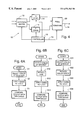
- FIG. 4 is a block diagram illustrating the basic functions of an embodiment of the invention wherein the color signals are supplied from a color video camera, the axis rotation and gain control being carried out external to the camera;
- FIG. 5 is a block diagram illustrating a second embodiment of the invention wherein axis rotation and gain control are carried out by circuits within a color video camera;
- FIGS. 6A-6C are flow diagrams illustrating methods of detecting pixel color according to the invention.
- the method of the present invention is used to identify the color of pixels in a field of video using the color difference signals R-Y and B-Y.
- the color difference signals assume various names in the art, such as UV, CbCr, Cb′Cr′, depending on the video encoding format. These various formats differ mainly in their scale and relative magnitude. More importantly, there are well-known methods for transforming from any system to another, and the exact system with which one works has no direct bearing on the present invention.
- the color difference signals are referred to as the red (V) signal and the blue (U) signal and the color space will be referred to as the UV color space for its 2-dimensional version at a constant luminance level, and the YUV color space for its 3-dimensional version, where Y represents luminance.
- video cameras perform mathematical transformations on the input data in order to produce a red and a blue color difference signal for each pixel. These calculations are performed to produce red (V) and blue (U) signals in accordance with specified standards for video signals, such as NTSC or PAL. Standard color processing involves applying gain to the U and V signals in order to generate levels of appropriate relative amplitude for the color being observed.
- colors that are predominantly along one axis of the UV color space such as green, yellow, red and blue, are considered.
- the invention will be described primarily as it applies to the identification of green pixels. However, it will be appreciated by those skilled in the art that the principles of the invention apply to other colors satisfying the above condition.
- FIGS. 1 and 3 represent the two-dimensional color space UV, defined by U and V orthogonal axes, which correspond to the color difference signals B-Y and R-Y from a color video camera.
- the negative V axis defines the region of interest because, as shown in FIG. 3, the green hue vector lies in the third quadrant and is displaced clockwise from the negative V axis so as to fall in the area identified as “green” in FIG. 1 .
- Standard color processing methods can be modified to take advantage of this fact in identifying green pixels in a field of video. The modification comprises the step of distorting the output signal in favor of the identification of green pixels. The distortion is accomplished by setting to zero the gains for the U signals and positive V signals. After performing these operations, the output signal is substantially a red or V signal which has only negative values and indicates only the negative red content of the scene captured by the video camera.
- the identification of green pixels merely requires determining whether the red signal is sufficiently negative to be considered green. Hence a comparison of the red signal to a prescribed threshold value is necessary for the final decision of whether the pixel is green or not. Any red values below (more negative than) the prescribed threshold indicate the presence of green.
- the prescribed threshold value is arbitrarily selected, based on the level of green desired for the specific application in which the method is used.
- the term “negative” is used in a relative sense rather than an absolute sense.
- the signals U and V are signed 8-bit numbers in two's complement format.
- the decimal value 128 defines the axis crossing point in FIG. 1 .
- a “negative” U axis signal is to the left of the crossing point and a “negative” V axis signal is below the crossing point.
- FIG. 6A is a flow diagram illustrating the steps in a method as just described.
- the color of interest the target color
- gain is selectively applied to the signals U and V to minimize or reduce to zero all signals except for those representing the region of interest. That is, if the color selected at S 1 is green, then at S 2 the signals U and positive values of the signal V are minimized leaving only (or primarily) negative values of the V signals.
- the V signal which now has only negative values, is compared with a threshold to determine if the V signal is sufficiently negative to be considered green.
- FIG. 6B illustrates a modification of the method shown in FIG. 6 A.
- This modification takes into account the fact that the target color (green) selected at S 11 also contains a small amount of negative blue color, the hue vector for green being displaced from the negative V axis in a clockwise direction by 29.4°.
- the U axis signal is rotated by 29.4° counterclockwise at S 12 . This rotation effectively places the green signal information on or near the negative V axis.
- the green information is in substantially the same region of the color space as the negative V signal, and the points of green are amplified by the negative V signal gain.
- the gains for U signals and positive V signals are set to zero, and the gain for negative V (green) signals is maximized at S 13 .
- the identification of green pixels can then be done as previously outlined, by comparing the negative V axis signal to a threshold value (S 14 ) to determine if the signal is sufficiently negative to be considered green.
- a threshold value S 14
- only one comparator is needed to compare the red signal to a prescribed threshold value.
- the comparator may be either an analog or a digital comparator.
- the rotation of the U axis signal is not limited to 29.4°.
- the optimum amount of rotation is dependent on the hue of the weeds to be detected. For example, if the weeds are a yellowish green, that is, the weed color has a high yellow component, the detection of yellowish green pixels is enhanced by rotating the U axis signal by more than 29.4°. On the other hand, if the weed color has a high negative red component then a rotation of less than 29.4° will provide maximum extraction of the color information.
- the prescribed threshold value is negative red for the purpose of green identification, but in general, it may have any value, depending on the target color, the color standards and encoding formats used, the exact modality of implementing the method within the logic circuitry and so on.
- FIG. 6C illustrates a further modification of the method shown in FIG. 6 A.
- the entire color space is rotated at S 32 .
- the degree or amount of rotation depends on the target color selected. Referring to FIG. 3, it is seen that yellow and blue lie generally about 13° off the U axis. By rotating the entire color space about 12° counterclockwise, both yellow and blue are moved near the U axis.
- gains are selectively applied depending on whether yellow or blue is the selected target color. For example, if yellow pixels are to be detected, S 33 minimizes positive and negative V axis signals and positive U axis signals so that the negative U axis signals are left as the dominant signals subjected to threshold comparison at S 34 .
- FIG. 4 is a block diagram of a system 10 that may be utilized to practice the methods, described above, of identifying the color of a pixel.
- the system 10 utilizes the color difference signals produced by a color video camera (not shown) and comprises a rotation matrix 12 (required only to practice the methods shown in FIGS. 6 B and 6 C), U and V gain amplifiers 14 and 16 , a micro controller 18 and a pixel compare circuit 20 .
- matrix 12 receives the color difference signals U and V produced by the camera and rotates one axis signal (assumed to be the U axis) toward another axis (assumed to be the V axis) in response to commands from controller 18 .
- the resulting V axis signal which now includes a negative blue component, is applied to V gain amplifier 16 and the signal U is applied to the U gain amplifier 14 .
- the U and V gain amplifiers 14 and 16 are controlled by controller 18 so that the output signal is minimized for all regions in the color space except in the region of interest. Assuming the region of interest is green, the controller 18 controls the U and V gain amplifiers to minimize the U and positive values of V and maximize negative values of V.
- the resulting gain controlled signals are applied to pixel compare circuit 20 where the signal corresponding to the color region of interest is compared with a reference value supplied by controller 18 over signal path 22 . Again assuming the region of interest is green, each negative V output from gain circuit 16 is compared with the reference value and if it is more negative than the reference value, pixel compare circuit 20 produces a signal on lead 24 indicating the pixel is green.
- the circuit 20 may be an analog device but a digital comparator is preferred.
- the method illustrated in FIG. 6C may be implemented by system 10 if the controller is programmed to apply commands to matrix 12 so as to rotate the entire color space.
- the method illustrated in FIG. 6A may be implemented by the system 10 if the controller is programmed to control matrix 12 so that no rotation is performed.
- matrix 12 is eliminated in this case and the color difference signals from the video camera are applied directly to the U and V gain circuits 14 and 16 .
- the system 10 is capable of recognizing a pixel of any target color.
- one of the gain circuits may be eliminated.
- the U axis gain circuit 14 is not required.
- the axis rotation matrix 12 receives the color signal output of a video camera.
- conventional color video cameras typically include an axis rotation matrix for color signal processing, as well as a micro controller and gain circuits. Therefore, the invention may, and preferably is, implemented by directly connecting the pixel compare circuit 20 to receive the color output signals from the camera. This arrangement is illustrated in FIG. 5 .
- the system 50 shown in FIG. 5 may be implemented using a camera comprising a Sony SS-1 3-chip set including a model CXD2163R digital signal processor (DSP) chip 52 , a model CXA2006Q analog gain control (AGC) chip 54 , and a model CXD2480R CCD Driver and Timing Control chip 56 .
- DSP digital signal processor
- AGC analog gain control
- CXD2480R CCD Driver and Timing Control chip 56 These three chips form a complete video camera for digitally processing analog signals produced by a CCD sensor 58 .
- Sensor 58 is mounted on the boom (not shown) of an agricultural sprayer and is provided with a lens 60 so that an image of a field in front of the sprayer is imaged onto the sensor.
- the CCD Driver and Timing circuits 56 control the “shutter speed” and readout of the analog color video signal from the sensor to AGC 54 .
- the analog video output signal from AGC 54 is applied to DSP 52 where it is first converted to a digital video signal by ADC 62 .
- the output of ADC 62 is then applied to a contour correction circuit 68 comprising two delay circuits 64 and a summer 66 .
- the contour correction circuit is described in U.S. Pat. No. 5,343,244 and produces output signals that are applied to a luminance signal processing circuit 70 and a chrominance signal processing circuit 72 .
- the contour corrected signal is first applied to a low pass filter (LPF) 74 and the output of filter 74 is applied to a matrix 76 that develops the chroma signals R, G and B.
- the RGB signals after white balancing and gamma correction by circuits not shown, are applied to a rotation and gain matrix 78 .
- Matrix 78 normally transforms the RGB signals into the color difference signals U (B-Y) V (R-Y), alternately producing 8-bit signals U and V at its output 80 .
- matrix 78 is also controlled to rotate the B-Y or U axis signals toward the R-Y or V axis as previously described, and minimize the U axis signals and the positive V axis signals.
- the DSP chip 52 includes a DSP micro controller 82 for controlling, via a serial data bus 84 , various circuits within the DSP, including the rotation and gain imparted to the color difference signals by matrix 78 .
- the DSP chip also includes an interface circuit 86 .
- a system controller 88 is connected to the DSP controller 82 via interface circuit 86 .
- Controller 88 is connected via a serial interface circuit 94 , a nozzle controller 92 and a CAN bus 98 to an input device (not shown) so that an operator may select the target color and set the color threshold level, that is, for example, how negative the V signal on path 80 must be in order to be classified as green by a pixel compare circuit 90 .
- the target color and is utilized in controller 88 to develop the gain and rotation signals. These signals are relayed to controller 82 which utilizes the signals to set the gains and rotation imparted to the pixel signals by matrix 78 .
- the target color is also utilized by controller 88 to develop the color threshold signal that is applied to pixel compare circuit 90 .
- the color threshold level provided by controller 88 may be a color corrected threshold which takes into account the luminance in a field of video.
- the color corrected threshold developed from pixel luminance in one field of video as described in our above-referenced concurrently filed application, is transferred to pixel compare circuit 90 prior to the next field. Compare circuit 90 then compares the color corrected threshold with the UN signals from matrix 78 .
- Compare circuit 90 does not utilize the U signal when the target color is green.
- the circuit compares the color corrected threshold level signal with the values of V produced by matrix 78 , and if V is more negative than the corrected threshold level then an output signal is made available to nozzle controller 92 indicating the pixel is the target color, i.e. green.
- Pixel compare circuit 90 is a programmable logic array. In addition to comparing for a target color, the circuit also counts the number of pixels of the target color occurring on each video scan line. Controller 92 samples the outputs from circuit 90 and also receives, via a CAN bus 98 , the on and off times for the nozzles and a weed size value input by an operator.
- a sprayer which may spray a material over a path having a width of up to 30 feet or more, is provided with a plurality of cameras. Each camera is aimed so as to view a different portion of the path to be sprayed.
- Controller 92 utilizes the green/not green signal from compare circuit 90 to determine, for each scan line, how many green pixels have been detected within each region. If the number of green pixels within a region exceeds the weed size value supplied via CAN bus 98 , then one of nozzle drivers 96 is actuated to activate the nozzle for that region.
- a sensor and a conventional circuit determine the time at which a nozzle is turned on, based on the travel of the sprayer and the camera to nozzle distance.
- the system 50 may be used to implement any of the methods illustrated in FIGS. 6A-6C to recognize any color by proper programming of the DSP controller 82 to set the proper rotation and gains in matrix 78 .
- the present invention provides a simple but reliable method of identifying pixels of a target color within a field of video.
- the technique requires only one comparator, in addition to the circuitry required for standard processing of video images.
- the various rotations that are to be performed before the final comparison can be achieved by manipulating the gains in a video camera color transformation matrix.
- the invention reduces the number of false detections due to insufficient chroma bandwidth, as discussed in the Background section, by minimizing the color gain in all but the region of interest, and compressing all other regions along one of the U or V axes. Since regions which are not of interest are compressed along one of the U or axes and receive no signal gain, the transitions from one color to another which transition across the target color are reduced.
Abstract
Description
Claims (10)
Priority Applications (1)
| Application Number | Priority Date | Filing Date | Title |
|---|---|---|---|
| US09/438,405 US6574363B1 (en) | 1998-11-13 | 1999-11-12 | Method for color detection in video images |
Applications Claiming Priority (2)
| Application Number | Priority Date | Filing Date | Title |
|---|---|---|---|
| US10824298P | 1998-11-13 | 1998-11-13 | |
| US09/438,405 US6574363B1 (en) | 1998-11-13 | 1999-11-12 | Method for color detection in video images |
Publications (1)
| Publication Number | Publication Date |
|---|---|
| US6574363B1 true US6574363B1 (en) | 2003-06-03 |
Family
ID=22321078
Family Applications (1)
| Application Number | Title | Priority Date | Filing Date |
|---|---|---|---|
| US09/438,405 Expired - Lifetime US6574363B1 (en) | 1998-11-13 | 1999-11-12 | Method for color detection in video images |
Country Status (4)
| Country | Link |
|---|---|
| US (1) | US6574363B1 (en) |
| AU (1) | AU1510900A (en) |
| CA (1) | CA2350712C (en) |
| WO (1) | WO2000030362A1 (en) |
Cited By (38)
| Publication number | Priority date | Publication date | Assignee | Title |
|---|---|---|---|---|
| US20010055428A1 (en) * | 2000-06-21 | 2001-12-27 | Fuji Photo Film Co., Ltd. | Image signal processor with adaptive noise reduction and an image signal processing method therefor |
| US20040091135A1 (en) * | 2002-11-07 | 2004-05-13 | Bourg Wilfred M. | Method for on-line machine vision measurement, monitoring and control of product features during on-line manufacturing processes |
| US6807315B1 (en) * | 1999-09-16 | 2004-10-19 | Silverbrook Research Pty Ltd | Method and apparatus for sharpening an image |
| WO2005104726A2 (en) * | 2004-04-27 | 2005-11-10 | Frito-Lay North America, Inc. | Method for on-line machine vision measurement, monitoring and control of organoleptic properties of products for on-line manufacturing processes |
| US20070115518A1 (en) * | 2005-11-22 | 2007-05-24 | Beyond Innovation Technology Co., Ltd. | Image processing method and apparatus for color enhancement and correction |
| US7875862B1 (en) | 2007-12-07 | 2011-01-25 | Jerry Wade Hudson | Ultraviolet plant eradication apparatus and method |
| US8789939B2 (en) | 1998-11-09 | 2014-07-29 | Google Inc. | Print media cartridge with ink supply manifold |
| US8823823B2 (en) | 1997-07-15 | 2014-09-02 | Google Inc. | Portable imaging device with multi-core processor and orientation sensor |
| US8866923B2 (en) | 1999-05-25 | 2014-10-21 | Google Inc. | Modular camera and printer |
| US8896724B2 (en) | 1997-07-15 | 2014-11-25 | Google Inc. | Camera system to facilitate a cascade of imaging effects |
| US8902333B2 (en) | 1997-07-15 | 2014-12-02 | Google Inc. | Image processing method using sensed eye position |
| US8902340B2 (en) | 1997-07-12 | 2014-12-02 | Google Inc. | Multi-core image processor for portable device |
| US8908075B2 (en) | 1997-07-15 | 2014-12-09 | Google Inc. | Image capture and processing integrated circuit for a camera |
| US8936196B2 (en) | 1997-07-15 | 2015-01-20 | Google Inc. | Camera unit incorporating program script scanner |
| US9030549B2 (en) | 2012-03-07 | 2015-05-12 | Blue River Technology, Inc. | Method and apparatus for automated plant necrosis |
| US9055221B2 (en) | 1997-07-15 | 2015-06-09 | Google Inc. | Portable hand-held device for deblurring sensed images |
| US20170102229A1 (en) * | 2015-04-15 | 2017-04-13 | General Electric Company | Data Acquisition Devices, Systems and Method for Analyzing Strain Sensors and Monitoring Turbine Component Strain |
| US9658201B2 (en) | 2013-03-07 | 2017-05-23 | Blue River Technology Inc. | Method for automatic phenotype measurement and selection |
| US9717171B2 (en) | 2013-03-07 | 2017-08-01 | Blue River Technology Inc. | System and method for automated odometry calibration for precision agriculture systems |
| US9846933B2 (en) | 2015-11-16 | 2017-12-19 | General Electric Company | Systems and methods for monitoring components |
| US9879981B1 (en) | 2016-12-02 | 2018-01-30 | General Electric Company | Systems and methods for evaluating component strain |
| US9909860B2 (en) | 2015-04-15 | 2018-03-06 | General Electric Company | Systems and methods for monitoring component deformation |
| US9932853B2 (en) | 2015-04-28 | 2018-04-03 | General Electric Company | Assemblies and methods for monitoring turbine component strain |
| US9953408B2 (en) | 2015-11-16 | 2018-04-24 | General Electric Company | Methods for monitoring components |
| US9967523B2 (en) | 2015-12-16 | 2018-05-08 | General Electric Company | Locating systems and methods for components |
| US10012552B2 (en) | 2015-11-23 | 2018-07-03 | General Electric Company | Systems and methods for monitoring component strain |
| US10126119B2 (en) | 2017-01-17 | 2018-11-13 | General Electric Company | Methods of forming a passive strain indicator on a preexisting component |
| US10132615B2 (en) | 2016-12-20 | 2018-11-20 | General Electric Company | Data acquisition devices, systems and method for analyzing passive strain indicators and monitoring turbine component strain |
| US10219449B2 (en) | 2013-03-07 | 2019-03-05 | Blue River Technology Inc. | System and method for plant dislodgement |
| US10327393B2 (en) | 2013-03-07 | 2019-06-25 | Blue River Technology Inc. | Modular precision agriculture system |
| US10345179B2 (en) | 2017-02-14 | 2019-07-09 | General Electric Company | Passive strain indicator |
| US10451499B2 (en) | 2017-04-06 | 2019-10-22 | General Electric Company | Methods for applying passive strain indicators to components |
| US10502551B2 (en) | 2017-03-06 | 2019-12-10 | General Electric Company | Methods for monitoring components using micro and macro three-dimensional analysis |
| US10697760B2 (en) | 2015-04-15 | 2020-06-30 | General Electric Company | Data acquisition devices, systems and method for analyzing strain sensors and monitoring component strain |
| US10872176B2 (en) | 2017-01-23 | 2020-12-22 | General Electric Company | Methods of making and monitoring a component with an integral strain indicator |
| US11087497B2 (en) | 2019-09-17 | 2021-08-10 | International Business Machines Corporation | Chemical detection system for water source |
| US11129343B2 (en) | 2015-03-06 | 2021-09-28 | Blue River Technology Inc. | Modular precision agriculture system |
| US11313673B2 (en) | 2017-01-24 | 2022-04-26 | General Electric Company | Methods of making a component with an integral strain indicator |
Families Citing this family (2)
| Publication number | Priority date | Publication date | Assignee | Title |
|---|---|---|---|---|
| US11832609B2 (en) | 2020-12-21 | 2023-12-05 | Deere & Company | Agricultural sprayer with real-time, on-machine target sensor |
| US11944087B2 (en) | 2020-12-21 | 2024-04-02 | Deere & Company | Agricultural sprayer with real-time, on-machine target sensor |
Citations (6)
| Publication number | Priority date | Publication date | Assignee | Title |
|---|---|---|---|---|
| US4167750A (en) * | 1975-02-20 | 1979-09-11 | Matsushita Electric Industrial Co., Ltd. | Color-difference signal modifying apparatus |
| US5028991A (en) * | 1988-08-30 | 1991-07-02 | Kabushiki Kaisha Toshiba | Image signal processing apparatus for use in color image reproduction |
| DE4132637A1 (en) | 1991-10-01 | 1993-04-08 | Walter Prof Dr Kuehbauch | Automatic weed removal on railway track with image recognition control - has tv cameras and processor to compute weed coverage and with spatially controlled spraying of track |
| WO1996012401A1 (en) | 1994-10-25 | 1996-05-02 | Rees Equipment Pty. Ltd. | Controller for agricultural sprayers |
| US5555022A (en) * | 1989-11-17 | 1996-09-10 | Sanyo Electric Co., Ltd. | White balance adjusting apparatus for automatically adjusting white balance in response to color information signal obtained from image sensing device |
| US5621480A (en) * | 1993-04-19 | 1997-04-15 | Mitsubishi Denki Kabushiki Kaisha | Image quality correction circuit and method based on color density |
Family Cites Families (3)
| Publication number | Priority date | Publication date | Assignee | Title |
|---|---|---|---|---|
| US4506293A (en) * | 1981-07-16 | 1985-03-19 | Rca Corporation | Independent fleshtone contours |
| US5488429A (en) * | 1992-01-13 | 1996-01-30 | Mitsubishi Denki Kabushiki Kaisha | Video signal processor for detecting flesh tones in am image |
| KR100365848B1 (en) * | 1997-03-06 | 2003-02-20 | 마츠시타 덴끼 산교 가부시키가이샤 | Pure red color detection circuit and color compensation circuit using the same |
-
1999
- 1999-11-12 US US09/438,405 patent/US6574363B1/en not_active Expired - Lifetime
- 1999-11-12 AU AU15109/00A patent/AU1510900A/en not_active Abandoned
- 1999-11-12 CA CA002350712A patent/CA2350712C/en not_active Expired - Lifetime
- 1999-11-12 WO PCT/IB1999/001980 patent/WO2000030362A1/en active Application Filing
Patent Citations (7)
| Publication number | Priority date | Publication date | Assignee | Title |
|---|---|---|---|---|
| US4167750A (en) * | 1975-02-20 | 1979-09-11 | Matsushita Electric Industrial Co., Ltd. | Color-difference signal modifying apparatus |
| US5028991A (en) * | 1988-08-30 | 1991-07-02 | Kabushiki Kaisha Toshiba | Image signal processing apparatus for use in color image reproduction |
| US5555022A (en) * | 1989-11-17 | 1996-09-10 | Sanyo Electric Co., Ltd. | White balance adjusting apparatus for automatically adjusting white balance in response to color information signal obtained from image sensing device |
| DE4132637A1 (en) | 1991-10-01 | 1993-04-08 | Walter Prof Dr Kuehbauch | Automatic weed removal on railway track with image recognition control - has tv cameras and processor to compute weed coverage and with spatially controlled spraying of track |
| US5621480A (en) * | 1993-04-19 | 1997-04-15 | Mitsubishi Denki Kabushiki Kaisha | Image quality correction circuit and method based on color density |
| WO1996012401A1 (en) | 1994-10-25 | 1996-05-02 | Rees Equipment Pty. Ltd. | Controller for agricultural sprayers |
| US5924239A (en) * | 1994-10-25 | 1999-07-20 | Rees Equipment Pty Ltd. | Controller for agricultural sprayers |
Cited By (114)
| Publication number | Priority date | Publication date | Assignee | Title |
|---|---|---|---|---|
| US8902340B2 (en) | 1997-07-12 | 2014-12-02 | Google Inc. | Multi-core image processor for portable device |
| US9544451B2 (en) | 1997-07-12 | 2017-01-10 | Google Inc. | Multi-core image processor for portable device |
| US9338312B2 (en) | 1997-07-12 | 2016-05-10 | Google Inc. | Portable handheld device with multi-core image processor |
| US8947592B2 (en) | 1997-07-12 | 2015-02-03 | Google Inc. | Handheld imaging device with image processor provided with multiple parallel processing units |
| US9137398B2 (en) | 1997-07-15 | 2015-09-15 | Google Inc. | Multi-core processor for portable device with dual image sensors |
| US8922670B2 (en) | 1997-07-15 | 2014-12-30 | Google Inc. | Portable hand-held device having stereoscopic image camera |
| US9432529B2 (en) | 1997-07-15 | 2016-08-30 | Google Inc. | Portable handheld device with multi-core microcoded image processor |
| US9237244B2 (en) | 1997-07-15 | 2016-01-12 | Google Inc. | Handheld digital camera device with orientation sensing and decoding capabilities |
| US9219832B2 (en) | 1997-07-15 | 2015-12-22 | Google Inc. | Portable handheld device with multi-core image processor |
| US9197767B2 (en) | 1997-07-15 | 2015-11-24 | Google Inc. | Digital camera having image processor and printer |
| US9191530B2 (en) | 1997-07-15 | 2015-11-17 | Google Inc. | Portable hand-held device having quad core image processor |
| US9191529B2 (en) | 1997-07-15 | 2015-11-17 | Google Inc | Quad-core camera processor |
| US9185246B2 (en) | 1997-07-15 | 2015-11-10 | Google Inc. | Camera system comprising color display and processor for decoding data blocks in printed coding pattern |
| US9185247B2 (en) | 1997-07-15 | 2015-11-10 | Google Inc. | Central processor with multiple programmable processor units |
| US9179020B2 (en) | 1997-07-15 | 2015-11-03 | Google Inc. | Handheld imaging device with integrated chip incorporating on shared wafer image processor and central processor |
| US9168761B2 (en) | 1997-07-15 | 2015-10-27 | Google Inc. | Disposable digital camera with printing assembly |
| US9143635B2 (en) | 1997-07-15 | 2015-09-22 | Google Inc. | Camera with linked parallel processor cores |
| US9560221B2 (en) | 1997-07-15 | 2017-01-31 | Google Inc. | Handheld imaging device with VLIW image processor |
| US9148530B2 (en) | 1997-07-15 | 2015-09-29 | Google Inc. | Handheld imaging device with multi-core image processor integrating common bus interface and dedicated image sensor interface |
| US9137397B2 (en) | 1997-07-15 | 2015-09-15 | Google Inc. | Image sensing and printing device |
| US9131083B2 (en) | 1997-07-15 | 2015-09-08 | Google Inc. | Portable imaging device with multi-core processor |
| US8823823B2 (en) | 1997-07-15 | 2014-09-02 | Google Inc. | Portable imaging device with multi-core processor and orientation sensor |
| US8836809B2 (en) | 1997-07-15 | 2014-09-16 | Google Inc. | Quad-core image processor for facial detection |
| US8866926B2 (en) | 1997-07-15 | 2014-10-21 | Google Inc. | Multi-core processor for hand-held, image capture device |
| US9124736B2 (en) | 1997-07-15 | 2015-09-01 | Google Inc. | Portable hand-held device for displaying oriented images |
| US8896724B2 (en) | 1997-07-15 | 2014-11-25 | Google Inc. | Camera system to facilitate a cascade of imaging effects |
| US8896720B2 (en) | 1997-07-15 | 2014-11-25 | Google Inc. | Hand held image capture device with multi-core processor for facial detection |
| US8902333B2 (en) | 1997-07-15 | 2014-12-02 | Google Inc. | Image processing method using sensed eye position |
| US9124737B2 (en) | 1997-07-15 | 2015-09-01 | Google Inc. | Portable device with image sensor and quad-core processor for multi-point focus image capture |
| US8902357B2 (en) | 1997-07-15 | 2014-12-02 | Google Inc. | Quad-core image processor |
| US8902324B2 (en) | 1997-07-15 | 2014-12-02 | Google Inc. | Quad-core image processor for device with image display |
| US8908069B2 (en) | 1997-07-15 | 2014-12-09 | Google Inc. | Handheld imaging device with quad-core image processor integrating image sensor interface |
| US8908075B2 (en) | 1997-07-15 | 2014-12-09 | Google Inc. | Image capture and processing integrated circuit for a camera |
| US8908051B2 (en) | 1997-07-15 | 2014-12-09 | Google Inc. | Handheld imaging device with system-on-chip microcontroller incorporating on shared wafer image processor and image sensor |
| US8913182B2 (en) | 1997-07-15 | 2014-12-16 | Google Inc. | Portable hand-held device having networked quad core processor |
| US8913151B2 (en) | 1997-07-15 | 2014-12-16 | Google Inc. | Digital camera with quad core processor |
| US8913137B2 (en) | 1997-07-15 | 2014-12-16 | Google Inc. | Handheld imaging device with multi-core image processor integrating image sensor interface |
| US9584681B2 (en) | 1997-07-15 | 2017-02-28 | Google Inc. | Handheld imaging device incorporating multi-core image processor |
| US8922791B2 (en) | 1997-07-15 | 2014-12-30 | Google Inc. | Camera system with color display and processor for Reed-Solomon decoding |
| US8928897B2 (en) | 1997-07-15 | 2015-01-06 | Google Inc. | Portable handheld device with multi-core image processor |
| US8934027B2 (en) | 1997-07-15 | 2015-01-13 | Google Inc. | Portable device with image sensors and multi-core processor |
| US8934053B2 (en) | 1997-07-15 | 2015-01-13 | Google Inc. | Hand-held quad core processing apparatus |
| US8936196B2 (en) | 1997-07-15 | 2015-01-20 | Google Inc. | Camera unit incorporating program script scanner |
| US8937727B2 (en) | 1997-07-15 | 2015-01-20 | Google Inc. | Portable handheld device with multi-core image processor |
| US9060128B2 (en) | 1997-07-15 | 2015-06-16 | Google Inc. | Portable hand-held device for manipulating images |
| US8947679B2 (en) | 1997-07-15 | 2015-02-03 | Google Inc. | Portable handheld device with multi-core microcoded image processor |
| US8953060B2 (en) | 1997-07-15 | 2015-02-10 | Google Inc. | Hand held image capture device with multi-core processor and wireless interface to input device |
| US8953178B2 (en) | 1997-07-15 | 2015-02-10 | Google Inc. | Camera system with color display and processor for reed-solomon decoding |
| US8953061B2 (en) | 1997-07-15 | 2015-02-10 | Google Inc. | Image capture device with linked multi-core processor and orientation sensor |
| US9143636B2 (en) | 1997-07-15 | 2015-09-22 | Google Inc. | Portable device with dual image sensors and quad-core processor |
| US9055221B2 (en) | 1997-07-15 | 2015-06-09 | Google Inc. | Portable hand-held device for deblurring sensed images |
| US8789939B2 (en) | 1998-11-09 | 2014-07-29 | Google Inc. | Print media cartridge with ink supply manifold |
| US8866923B2 (en) | 1999-05-25 | 2014-10-21 | Google Inc. | Modular camera and printer |
| US7289681B2 (en) | 1999-09-16 | 2007-10-30 | Silverbrook Research Pty Ltd | Method of sharpening image using luminance channel |
| US20050047674A1 (en) * | 1999-09-16 | 2005-03-03 | Walmsley Simon Robert | Apparatus for sharpening an image using a luminance channel |
| US7187807B2 (en) | 1999-09-16 | 2007-03-06 | Silverbrook Research Pty Ltd | Apparatus for sharpening an image using a luminance channel |
| US6807315B1 (en) * | 1999-09-16 | 2004-10-19 | Silverbrook Research Pty Ltd | Method and apparatus for sharpening an image |
| US20070122032A1 (en) * | 1999-09-16 | 2007-05-31 | Silverbrook Research Pty Ltd | Method of pre-processing an image to be printed in a hand-held camera |
| US20080123165A1 (en) * | 1999-09-16 | 2008-05-29 | Silverbrook Research Pty Ltd | Method Of Sharpening An Rgb Image For Sending To A Printhead |
| US7787163B2 (en) | 1999-09-16 | 2010-08-31 | Silverbrook Research Pty Ltd | Method of sharpening an RGB image for sending to a printhead |
| US20050047675A1 (en) * | 1999-09-16 | 2005-03-03 | Walmsley Simon Robert | Method of sharpening image using luminance channel |
| US7349572B2 (en) | 1999-09-16 | 2008-03-25 | Silverbrook Research Pty Ltd | Method of pre-processing an image to be printed in a hand-held camera |
| US20010055428A1 (en) * | 2000-06-21 | 2001-12-27 | Fuji Photo Film Co., Ltd. | Image signal processor with adaptive noise reduction and an image signal processing method therefor |
| US6882754B2 (en) * | 2000-06-21 | 2005-04-19 | Fuji Photo Film Co., Ltd. | Image signal processor with adaptive noise reduction and an image signal processing method therefor |
| WO2004044841A3 (en) * | 2002-11-07 | 2005-01-20 | Univ Mcmaster | Method for on-line machine vision measurement, monitoring and control of product features during on-line manufacturing processes |
| US7068817B2 (en) * | 2002-11-07 | 2006-06-27 | Mcmaster University | Method for on-line machine vision measurement, monitoring and control of product features during on-line manufacturing processes |
| WO2004044841A2 (en) * | 2002-11-07 | 2004-05-27 | Mcmaster University | Method for on-line machine vision measurement, monitoring and control of product features during on-line manufacturing processes |
| US20040091135A1 (en) * | 2002-11-07 | 2004-05-13 | Bourg Wilfred M. | Method for on-line machine vision measurement, monitoring and control of product features during on-line manufacturing processes |
| WO2005104726A3 (en) * | 2004-04-27 | 2006-11-16 | Frito Lay North America Inc | Method for on-line machine vision measurement, monitoring and control of organoleptic properties of products for on-line manufacturing processes |
| WO2005104726A2 (en) * | 2004-04-27 | 2005-11-10 | Frito-Lay North America, Inc. | Method for on-line machine vision measurement, monitoring and control of organoleptic properties of products for on-line manufacturing processes |
| US7986833B2 (en) * | 2005-11-22 | 2011-07-26 | Beyond Innovation Technology Co., Ltd. | Image processing method and apparatus for color enhancement and correction |
| US20070115518A1 (en) * | 2005-11-22 | 2007-05-24 | Beyond Innovation Technology Co., Ltd. | Image processing method and apparatus for color enhancement and correction |
| US7875862B1 (en) | 2007-12-07 | 2011-01-25 | Jerry Wade Hudson | Ultraviolet plant eradication apparatus and method |
| US11510355B2 (en) | 2012-03-07 | 2022-11-29 | Blue River Technology Inc. | Method and apparatus for automated plant necrosis |
| US9064173B2 (en) | 2012-03-07 | 2015-06-23 | Blue River Technology, Inc. | Method and apparatus for automated plant necrosis |
| US10524402B2 (en) | 2012-03-07 | 2020-01-07 | Blue River Technology Inc. | Method and apparatus for automated plan necrosis |
| US11058042B2 (en) | 2012-03-07 | 2021-07-13 | Blue River Technology Inc. | Method and apparatus for automated plant necrosis |
| US9030549B2 (en) | 2012-03-07 | 2015-05-12 | Blue River Technology, Inc. | Method and apparatus for automated plant necrosis |
| US9756771B2 (en) | 2012-03-07 | 2017-09-12 | Blue River Technology Inc. | Method and apparatus for automated plant necrosis |
| US10219449B2 (en) | 2013-03-07 | 2019-03-05 | Blue River Technology Inc. | System and method for plant dislodgement |
| US9658201B2 (en) | 2013-03-07 | 2017-05-23 | Blue River Technology Inc. | Method for automatic phenotype measurement and selection |
| US10390497B2 (en) | 2013-03-07 | 2019-08-27 | Blue River Technology, Inc. | System and method for plant treatment |
| US10327393B2 (en) | 2013-03-07 | 2019-06-25 | Blue River Technology Inc. | Modular precision agriculture system |
| US10175362B2 (en) | 2013-03-07 | 2019-01-08 | Blue River Technology Inc. | Plant treatment based on morphological and physiological measurements |
| US9717171B2 (en) | 2013-03-07 | 2017-08-01 | Blue River Technology Inc. | System and method for automated odometry calibration for precision agriculture systems |
| US11744189B2 (en) | 2013-07-11 | 2023-09-05 | Blue River Technology Inc. | Plant treatment based on morphological and physiological measurements |
| US11445665B2 (en) | 2013-07-11 | 2022-09-20 | Blue River Technology Inc. | Plant treatment based on morphological and physiological measurements |
| US11647701B2 (en) | 2013-07-11 | 2023-05-16 | Blue River Technology Inc. | Plant treatment based on morphological and physiological measurements |
| US10761211B2 (en) | 2013-07-11 | 2020-09-01 | Blue River Technology Inc. | Plant treatment based on morphological and physiological measurements |
| US11350622B2 (en) | 2013-07-26 | 2022-06-07 | Blue River Technology Inc. | System and method for plant treatment based on neighboring effects |
| US10537071B2 (en) | 2013-07-26 | 2020-01-21 | Blue River Technology Inc. | System and method for individual plant treatment based on neighboring effects |
| US10098273B2 (en) | 2014-02-21 | 2018-10-16 | Blue River Technology Inc. | System and method for automated odometry calibration for precision agriculture systems |
| US11197409B2 (en) | 2014-02-21 | 2021-12-14 | Blue River Technology Inc. | System and method for automated odometry calibration for precision agriculture systems |
| US10617071B2 (en) | 2014-02-21 | 2020-04-14 | Blue River Technology Inc. | Modular precision agriculture system |
| US11659793B2 (en) | 2015-03-06 | 2023-05-30 | Blue River Technology Inc. | Modular precision agriculture system |
| US11129343B2 (en) | 2015-03-06 | 2021-09-28 | Blue River Technology Inc. | Modular precision agriculture system |
| US9869545B2 (en) * | 2015-04-15 | 2018-01-16 | General Electric Company | Data acquisition devices, systems and method for analyzing strain sensors and monitoring turbine component strain |
| US20170102229A1 (en) * | 2015-04-15 | 2017-04-13 | General Electric Company | Data Acquisition Devices, Systems and Method for Analyzing Strain Sensors and Monitoring Turbine Component Strain |
| US9909860B2 (en) | 2015-04-15 | 2018-03-06 | General Electric Company | Systems and methods for monitoring component deformation |
| US10697760B2 (en) | 2015-04-15 | 2020-06-30 | General Electric Company | Data acquisition devices, systems and method for analyzing strain sensors and monitoring component strain |
| US9932853B2 (en) | 2015-04-28 | 2018-04-03 | General Electric Company | Assemblies and methods for monitoring turbine component strain |
| US9846933B2 (en) | 2015-11-16 | 2017-12-19 | General Electric Company | Systems and methods for monitoring components |
| US9953408B2 (en) | 2015-11-16 | 2018-04-24 | General Electric Company | Methods for monitoring components |
| US10012552B2 (en) | 2015-11-23 | 2018-07-03 | General Electric Company | Systems and methods for monitoring component strain |
| US9967523B2 (en) | 2015-12-16 | 2018-05-08 | General Electric Company | Locating systems and methods for components |
| US9879981B1 (en) | 2016-12-02 | 2018-01-30 | General Electric Company | Systems and methods for evaluating component strain |
| US10132615B2 (en) | 2016-12-20 | 2018-11-20 | General Electric Company | Data acquisition devices, systems and method for analyzing passive strain indicators and monitoring turbine component strain |
| US10126119B2 (en) | 2017-01-17 | 2018-11-13 | General Electric Company | Methods of forming a passive strain indicator on a preexisting component |
| US10872176B2 (en) | 2017-01-23 | 2020-12-22 | General Electric Company | Methods of making and monitoring a component with an integral strain indicator |
| US11313673B2 (en) | 2017-01-24 | 2022-04-26 | General Electric Company | Methods of making a component with an integral strain indicator |
| US10345179B2 (en) | 2017-02-14 | 2019-07-09 | General Electric Company | Passive strain indicator |
| US10502551B2 (en) | 2017-03-06 | 2019-12-10 | General Electric Company | Methods for monitoring components using micro and macro three-dimensional analysis |
| US10451499B2 (en) | 2017-04-06 | 2019-10-22 | General Electric Company | Methods for applying passive strain indicators to components |
| US11087497B2 (en) | 2019-09-17 | 2021-08-10 | International Business Machines Corporation | Chemical detection system for water source |
Also Published As
| Publication number | Publication date |
|---|---|
| WO2000030362A1 (en) | 2000-05-25 |
| AU1510900A (en) | 2000-06-05 |
| CA2350712C (en) | 2004-05-25 |
| CA2350712A1 (en) | 2000-05-25 |
Similar Documents
| Publication | Publication Date | Title |
|---|---|---|
| US6574363B1 (en) | Method for color detection in video images | |
| US6788813B2 (en) | System and method for effectively performing a white balance operation | |
| US5880782A (en) | System and method for controlling exposure of a video camera by utilizing luminance values selected from a plurality of luminance values | |
| JP4677753B2 (en) | Moving image processing apparatus and method | |
| US7009639B1 (en) | Color imaging by independently controlling gains of each of R, Gr, Gb, and B signals | |
| US7307656B2 (en) | White balance correcting device | |
| CN101472188A (en) | White balance control device and white balance control method | |
| EP3342151A1 (en) | Parameter adjustments based on strength change | |
| CN102474628A (en) | Image processing method and device, image processing program, and medium having said program recorded thereon | |
| EP1347654A3 (en) | Video correction apparatus and method, video correction program, and recording medium on which the program is recorded | |
| US7173656B1 (en) | Method and apparatus for processing digital pixel output signals | |
| WO2000073974A1 (en) | Method and system for identifying an image feature | |
| US6930710B1 (en) | Method of and apparatus for processing a video image | |
| CN112037128B (en) | Panoramic video stitching method | |
| US8743236B2 (en) | Image processing method, image processing apparatus, and imaging apparatus | |
| EP0563877B1 (en) | Color signal clipping or limiting apparatus | |
| US5815159A (en) | Spatially mapped monochrome display in a color image | |
| JPH04205070A (en) | Method for extracting specific object | |
| CA2350082C (en) | Color enhancement method | |
| EP1492356A2 (en) | Method for color detection in video images | |
| JP2009506722A (en) | Improved color difference filter for white balance statistics calculation | |
| JPH0226193A (en) | White balance control circuit | |
| JPS5953980A (en) | Color pattern recognizing method | |
| CA2505883C (en) | Color enhancement method | |
| KR101713255B1 (en) | Device and method for making high dynamic range image |
Legal Events
| Date | Code | Title | Description |
|---|---|---|---|
| AS | Assignment |
Owner name: FLEXI-COIL LTD., CANADA Free format text: ASSIGNMENT OF ASSIGNORS INTEREST;ASSIGNORS:CLASSEN, BRIAN J.;CHRISTOFF, JORDAN C.;REEL/FRAME:010563/0256;SIGNING DATES FROM 20000210 TO 20000214 |
|
| STCF | Information on status: patent grant |
Free format text: PATENTED CASE |
|
| AS | Assignment |
Owner name: CNH AMERICA LLC, PENNSYLVANIA Free format text: ASSIGNMENT OF ASSIGNORS INTEREST;ASSIGNOR:FLEXI-COIL LTD.;REEL/FRAME:015044/0503 Effective date: 20040805 |
|
| AS | Assignment |
Owner name: CNH CANADA, LTD., CANADA Free format text: ASSIGNMENT OF ASSIGNORS INTEREST;ASSIGNOR:FLEXI-COIL LTD.;REEL/FRAME:015442/0569 Effective date: 20040907 |
|
| AS | Assignment |
Owner name: CNH CANADA, LTD., CANADA Free format text: ASSIGNMENT OF ASSIGNORS INTEREST;ASSIGNOR:CNH AMERICA LLC;REEL/FRAME:015478/0133 Effective date: 20041208 |
|
| FPAY | Fee payment |
Year of fee payment: 4 |
|
| FPAY | Fee payment |
Year of fee payment: 8 |
|
| FPAY | Fee payment |
Year of fee payment: 12 |
|
| AS | Assignment |
Owner name: CNH INDUSTRIAL CANADA, LTD., CANADA Free format text: CHANGE OF NAME;ASSIGNOR:CNH CANADA, LTD.;REEL/FRAME:034035/0996 Effective date: 20140301 |