US6584237B1 - Method and apparatus for expanding image data - Google Patents

Method and apparatus for expanding image data Download PDF

Info

Publication number
US6584237B1
US6584237B1 US09/642,813 US64281300A US6584237B1 US 6584237 B1 US6584237 B1 US 6584237B1 US 64281300 A US64281300 A US 64281300A US 6584237 B1 US6584237 B1 US 6584237B1
Authority
US
United States
Prior art keywords
pixel
image data
original image
along
magnifying power
Prior art date
Legal status (The legal status is an assumption and is not a legal conclusion. Google has not performed a legal analysis and makes no representation as to the accuracy of the status listed.)
Expired - Lifetime, expires
Application number
US09/642,813
Inventor
Nobuaki Abe
Current Assignee (The listed assignees may be inaccurate. Google has not performed a legal analysis and makes no representation or warranty as to the accuracy of the list.)
Pentax Corp
Hoya Corp
Original Assignee
Pentax Corp
Priority date (The priority date is an assumption and is not a legal conclusion. Google has not performed a legal analysis and makes no representation as to the accuracy of the date listed.)
Filing date
Publication date
Application filed by Pentax Corp filed Critical Pentax Corp
Assigned to ASAHI KOGAKU KOGYO KABUSHIKI KAISHA reassignment ASAHI KOGAKU KOGYO KABUSHIKI KAISHA ASSIGNMENT OF ASSIGNORS INTEREST (SEE DOCUMENT FOR DETAILS). Assignors: ABE, NOBUAKI
Assigned to PENTAX CORPORATION reassignment PENTAX CORPORATION CHANGE OF NAME (SEE DOCUMENT FOR DETAILS). Assignors: KAISHA, ASAKI KOGAKU KOGYO KABUSHIKI
Application granted granted Critical
Publication of US6584237B1 publication Critical patent/US6584237B1/en
Assigned to HOYA CORPORATION reassignment HOYA CORPORATION MERGER (SEE DOCUMENT FOR DETAILS). Assignors: PENTAX CORPORATION
Assigned to Pentax Ricoh Imaging Company, Ltd. reassignment Pentax Ricoh Imaging Company, Ltd. CORPORATE SPLIT Assignors: HOYA CORPORATION
Adjusted expiration legal-status Critical
Expired - Lifetime legal-status Critical Current

Links

Images

Classifications

    • GPHYSICS
    • G06COMPUTING; CALCULATING OR COUNTING
    • G06TIMAGE DATA PROCESSING OR GENERATION, IN GENERAL
    • G06T3/00Geometric image transformation in the plane of the image
    • G06T3/40Scaling the whole image or part thereof
    • G06T3/4007Interpolation-based scaling, e.g. bilinear interpolation
    • HELECTRICITY
    • H04ELECTRIC COMMUNICATION TECHNIQUE
    • H04NPICTORIAL COMMUNICATION, e.g. TELEVISION
    • H04N5/00Details of television systems
    • H04N5/222Studio circuitry; Studio devices; Studio equipment
    • H04N5/262Studio circuits, e.g. for mixing, switching-over, change of character of image, other special effects ; Cameras specially adapted for the electronic generation of special effects
    • H04N5/2628Alteration of picture size, shape, position or orientation, e.g. zooming, rotation, rolling, perspective, translation

Definitions

  • the present invention relates to a method and apparatus for expanding original image data to obtain expanded-image data composed of larger number of pixels than that of the original image data.
  • an interpolation processing such as a linear interpolation
  • pixels are interpolated so that the expanded-image is generated.
  • an object of a present invention is to provide a method and apparatus for expanding original image data, while limiting the degradation of picture quality.
  • An apparatus for expanding original image data according to the present invention expands the original image data.
  • the original image data is arranged in a matrix and is composed of a determined number of pixels.
  • the expanded-image data is partitioned into a plurality of blocks composed of a plurality of pixels.
  • the apparatus has a magnifying power setting processor, a pixel arranger, a shifting processor, a magnifying power inspector and an expanded-image generating processor.
  • the magnifying power setting processor sets a magnifying power regarding at least of a width direction and a length direction in the original image data.
  • the pixel arranger arranges each pixel in said original image data at a position corresponding to a center position of each of said plurality of blocks in accordance with said magnifying power.
  • the expanded-image generating processor generates the expanded-image data corresponding to the magnifying power by applying a fluency transform to each pixel in the original image data.
  • the plurality of pixels in each block is generated at pixel generating positions.
  • the magnifying power inspector inspects whether the magnifying power is odd numbered.
  • the shifting processor relatively shifts the pixel generating positions with respect to each corresponding pixel of original image data by a shifting-amount, corresponding to the magnifying power, such that each arranged pixel of original image data is off-center with respect to the plurality of blocks.
  • the fluency transform is executed, the variation of pixel value between pixels becomes smooth, and the picture quality is maintained in the process of expansion processing. Further, the fluency transform is executed after the shifting process is performed when the magnifying power is odd numbered, so that the variation of pixel value between pixels becomes smooth.
  • FIG. 1 is a block diagram of an expanded-image generating apparatus of an embodiment.
  • FIG. 2 is a view showing an expansion processing.
  • FIGS. 3A, 3 B, 3 C and 3 D are view showing fluency functions varying with parameter m.
  • FIG. 5 is a view showing an interpolation processing by a fluency transform.
  • FIG. 6 is a view showing the fluency transform along a horizontal direction.
  • FIG. 7 is a view showing a table T 1 indicating 8 pixel values along the horizontal direction in a block.
  • FIG. 8 is a view showing the fluency transform along a vertical direction.
  • FIG. 9 is a view showing a table T 2 representing 8 pixel values along the vertical direction in the block.
  • FIG. 10 is a view showing the fluency transform along the horizontal direction in the case in which the magnifying power is odd number.
  • FIG. 11 is a view showing a table T 3 representing 3 pixel values along the vertical direction in the block.
  • FIG. 12 is a view showing pixel values along the horizontal direction in the block.
  • FIG. 13 is a view showing 3 ⁇ 3 pixel values including an unchanging pixel value in the block
  • FIG. 14 is a view showing a shift processing along the horizontal direction.
  • FIG. 15 is a view showing a table T 4 representing pixel values obtained by shift processing.
  • FIG. 16 is a view showing a shift processing along the vertical direction.
  • FIG. 17 is a view showing a flowchart of the process for obtaining the expanded-image data.
  • FIG. 1 is a block diagram of an expanded-image generating apparatus of an embodiment of the present invention.
  • a memory M 1 original image data composed of luminance data Y and color difference data Cb, Cr is stored.
  • the original image data is obtained by being photographed by a digital still camera.
  • the original image data is composed of a plurality of pixels, and the plurality of pixels are arranged in a matrix.
  • the luminance data Y and color difference data Cb, Cr corresponding to one frame worth of the original image data are stored in an independent area of the memory M 1 , respectively.
  • the luminance data Y and color difference data Cb, Cr are fed to an expanded-image generating apparatus 10 , and are subjected to an expansion processing, separately.
  • the expanded-image generating apparatus 10 has a magnifying power setting processor 11 , a shifting processor 12 and an expanded-image generating processor 13 .
  • a CPU controls the expanded-image generating apparatus as a whole, and an input device (not shown) for selecting a magnifying power is provided.
  • the magnifying power is set in the magnifying power setting processor 11 .
  • the magnifying power is an integer number.
  • the shifting processor 12 an arrangement of each pixel in the original image data is performed in accordance with a value of the magnifying power. Further, in the shifting processor 12 , a shift processing regarding a pixel position of arranged pixels of the original image data is executed when the magnifying power is odd numbered, on the other hand, the shift processing is not executed when the magnifying power is even numbered.
  • the fluency transform is executed to each pixel in the original image data, so that expanded-image data, which has a larger number of pixels than that of the original image data, is obtained.
  • the expanded-image data is fed to a memory M 2 .
  • the luminance data Y and color difference data Cb, Cr corresponding to one frame worth of the expanded-image data are fed to a display device (not shown), thus the expanded-image is displayed on the display device.
  • FIG. 2 is a view showing an expansion processing.
  • the original image data P is composed of “A ⁇ C” pixels, “A” pixels are arranged along a horizontal direction and “C” pixels are arranged along a vertical direction.
  • a range of values of each pixel P yx is 0 to 255.
  • pixel values are also represented by “P yx ”.
  • x-y coordinates are defined with respect to the original image data P.
  • a top-left corner of the original image data P is set to an origin, an x-axis is parallel to the horizontal direction and a y-axis is parallel to the vertical direction.
  • a pixel P ts shown in FIG. 2 is positioned at the s-th pixel along the x-axis and the t-th pixel along the y-axis.
  • Each pixel in the original image data P is subject to the fluency transform along the horizontal (x-axis) and vertical (y-axis) direction, in accordance with the magnifying power
  • the pixel P ts is subject to the fluency transform along the horizontal direction, thus block BP composed of 3 pixels along the horizontal direction is generated.
  • a size of the pixel J yx is equal to that of the pixel P yx .
  • the expanded-image data J partitioned into a plurality of blocks B including the block B 0 , each of which is composed of 3 ⁇ 3 pixels, is generated.
  • a position of the block B 0 in the expanded-image data J corresponds to a position of the pixel P ts in the original image data P, therefore, the block B 0 is positioned at the s-th block along the horizontal direction and the t-th block along the vertical direction.
  • the position of each of the blocks B in the expanded-image data J corresponds to the position of the corresponding pixel P yx in the original image data P.
  • an x′-axis and a y′-axis are defined with respect to the horizontal direction and the vertical direction respectively, and each pixel in the original image data P is represented by “I′ y′x′ ”.
  • the pixel J yx in the expanded-image data J and the pixel “I′ y′x′ ” satisfy the following formula.
  • Each block B is a square block, and a pixel number along the x′-axis and the y′-axis are both of “3”. Therefore, a pixel number along the horizontal (width) direction and the vertical (length) direction in the original image data P are “ 3 A” and “ 3 C” respectively, and the pixel number of the expanded-image data J is “9 ⁇ A ⁇ C”.
  • the magnifying power means a ratio of the pixel number along the horizontal/vertical direction in the original image data P to the pixel number along the horizontal/vertical direction in the expanded-image data J. Therefore, a size of the expanded-image data J to a size of the original image data P is the square of the magnifying power. For example, in FIG. 2, the magnifying power is “3” and the expanded-image data has a size of 9 times of the original image data P.
  • the fluency transform is explained. Since the fluency transform is based on a fluency function, the fluency function will be described before the explanation of the fluency transform.
  • the fluency function named by professors Kamada and Toraichi, is known as a function, which represents various signals appropriately, for example, disclosed in a Mathematical Physics Journal (SURI-KAGAIU) No.363, pp8-12 (1993), published in Japan. To begin with, a fluency function space is defined as follows.
  • the fluency function space of order m “ m S” is constructed by a function system, composed of an (m ⁇ 2)-times continuously differentiable piecewise polynomial of degree m ⁇ 1.
  • the fluency function is a staircase (scaling) function when m is 1.
  • the function system characterizing the fluency function space m S and corresponding to an impulse response, is derived from a biorthogonal sampling basis theorem composed of a pair of a sampling basis and its biorthogonal basis.
  • f n ⁇ - ⁇ ⁇ ⁇ f ⁇ ( t ) ⁇ [ S * m ] _ ⁇ ⁇ ⁇ ( t - n ) _ ⁇ ⁇ t ( 6 )
  • the formula (5) indicates a function of the fluency transform derived from the sample value, and represents an expansion form, in which the sampling value sequences is a expansion coefficient.
  • the formula (6) indicates a function of the fluency inverse transform derived from the function of the fluency transform, and represents an operator, which obtains the sampling value sequences from the function of the fluency transform in the form of a integral transform.
  • p is an arbitrary integer
  • a bar expressed above “ ⁇ ” in the formula (6) represents a conjugated complex of ⁇ .
  • an orthogonal transform is derived from a fluency transform theorem.
  • the theorem satisfies the following two formulae for an arbitrary function f ⁇ m S.
  • ⁇ (u) is a function of the fluency function space m S and is expressed by using a Dirac delta function ⁇ . “u” is an arbitrary variable.
  • the formula (7) is designated as a fluency orthogonal transform
  • the formula (8) is designated as a fluency inverse orthogonal transform.
  • the fluency orthogonal transform expressed by the formula (7) can transform discrete sample values to continuous function values. Accordingly, in this embodiment, the fluency orthogonal transform is utilized for expanding the original image data. Namely, the fluency transform is executed to each pixel of the original image data P, and then the expanded-image data J is generated on the basis of the continuous function values.
  • the order “m” of the fluency function space m S can be expressed as a parameter “m” of the fluency function, and when the parameter “m” is set to “1,2, . . . ” in order, the fluency function are represented as shown below.
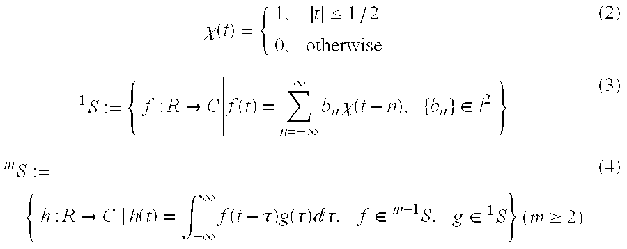
  • the most simple function system in the fluency function is obtained by setting the function “f(t) ⁇ 1 S” in the formula (3) to the rectangular function, which is represented by “ ⁇ (t)” in the formula (2), in place of the staircase function, and setting the function g ⁇ 1 S represented in the formula (4) to the above rectangular function “f(t)”.
  • the function f(t) represented in the formula (3) becomes a rectangular function by applying a Delta ( ⁇ ) function to an input function of the formula (3) in place of the rectangular function expressed by the formula (2).
  • the rectangular function f(t) is utilized for a function of the convolution integral in place of the function g( ⁇ ) represented in the formula (4), when transforming the function space m ⁇ 1 S to the function space m S.
  • An input value at the formula (3) becomes the ⁇ function shown in FIG. 3A in place of the rectangular function ⁇ (t) represented in the formula (2).
  • the value of the ⁇ function is 1 when variable t is ⁇ , and is 0 when variable t is not ⁇ .
  • the fluency function g(t) obtained by the formula (10) is, as shown in FIG. 3C, a triangular function.
  • the fluency function varies with the parameter m.
  • normalized function shown in FIG. 4 is applied to the convolution integral in place of the function f(t) shown in FIG. 3 B.
  • the normalized function f(t) is normalized as for an area, which is formed based on the t-axis and the function f(t), such that the area of the function f(t) is always 1.
  • FIG. 5 is a view showing an interpolation processing by the fluency transform. Note that, for ease of explanation, the fluency transform is executed for only the horizontal direction, or x-axis. The magnification is “8”.
  • three pixels P ts ⁇ 1 , P ts , P ts+1 , adjoining each other in the original image data P, are subjected to the fluency transform by the formula (7) along the horizontal direction.
  • Each pixel value of the three pixels P ts ⁇ 1 , P ts , P ts+1 is different respectively.
  • the input function F(u) at the formula (7) corresponds to each pixel value of the three pixels P ts ⁇ 1 , P ts , P ts+1 .
  • the output function f(t) in the formula (7) corresponds to the fluency functions shown in FIGS. 3A to 3 D. Therefore, by the fluency orthogonal transform, the output function f(t) having continuous values is generated.
  • an output function f s obtained by executing the fluency transform to the pixel value P ts , is a rectangular function, as shown in FIG. 5 .
  • the range of the output function f s along the x-axis corresponds to the range of the horizontal direction of the block BP (represented by “L” in FIG. 5 ).
  • the range of the output functions f s ⁇ 1 , f s+1 obtained by executing the fluency transform to the pixel values P ts ⁇ 1 , P ts+1 , does not overlap the range of the output function f s .
  • each of the functions f s ⁇ 1 , f s , f s+1 obtained by the formula (7) and corresponding to the pixel value P ts ⁇ 1 , P ts , P ts+1 respectively, is a triangular function.
  • each pixel value represented by the bar Q, is obtained by adding each value of the functions f s ⁇ 1 , f s , f s+1 .
  • each value of the functions f s ⁇ 1 , f s , f s+1 corresponding to each position of 8 pixels in the horizontal direction of the block BP, is added, so that each pixel value of 8 pixels along the horizontal direction (x-axis) is obtained.
  • the pixel value Z 3 is obtained by adding the pixel value Z 2 , which is the value of the function f s , and the pixel value Z 1 , which is the value of the function f s+1 .
  • each pixel value of the block BP, corresponding to the pixel P ts is calculated on the basis of the pixel value P ts ⁇ 1 , P ts+1 , and other adjacent pixels in the original image data P.
  • the fluency transform along the vertical direction (y-axis) is executed to the block BP, so that the block B 0 composed of 8 ⁇ 8 pixels is generated.
  • the expanded-image data J is generated. Each pixel value of the expanded-image data J depends upon the parameter m.
  • the parameter m is one of 1 to 3, and adjacent pixels to the pixel P ts , necessary for finding each pixel of the block BP, are represented by P ts+2 , P ts ⁇ 1 , P ts+1 , P ts+2 , P t ⁇ 2s , P t ⁇ 1s , P t+1s , P t+2s .
  • values of the pixels P ts ⁇ 2 , P ts ⁇ 1 , P ts+1 , P ts+2 , P t ⁇ 2s , P t ⁇ 1s , P t+1s , P t+2s are also expressed by “P ts ⁇ 2 , P ts ⁇ 1 , P ts+1 , P ts+2 , P t ⁇ 2s , P t ⁇ 1s , P t+1s , P t+2s ”.
  • FIG. 6 is a view showing the fluency transform along the horizontal direction (x-axis).
  • the positions of 8 pixels in the block BP are expressed by “0, 1, 2 . . . 7” in order.
  • the pixels P ts ⁇ 2 , P ts ⁇ 1 , P ts+1 , P ts+2 , P t ⁇ 2s , P t ⁇ 1s , P t+1s , P t+2s are subject to the fluency transform in the horizontal direction, at the center of each block generated by the fluency transform.
  • pixels represented by “I 0 , I 1 , I 2 , I 3 , I 4 , I 5 , I 6 , I 7 ” in FIG. 6, are based on the pixels P ts ⁇ 2 , P ts ⁇ 1 , P ts , P ts+1 , P ts+2 .
  • FIG. 7 is a view showing a table T 1 indicating 8 pixel values along the horizontal direction in the block BP, obtained by the fluency transform.
  • table T 1 pixel values corresponding to the parameter 1 , 2 and 3 respectively, are shown, and each pixel value is obtained on the basis of the formula (7).
  • pixel values along horizontal direction are also represented by “I 0 , I 1 , I 2 , . . . I 7 ”, which are identical to the 8 pixels along the horizontal direction.
  • the pixel values I 0 to I 7 are generated on the basis of the pixel values P ts ⁇ 1 , P ts , P ts+1 and the addition of the value of the function f s ⁇ 1 , f s , f s+1 at the formula (7). Namely, the pixel values I 0 to I 7 are respectively generated by adding each value of the functions f s ⁇ 1 , f s , f s+1 , which corresponds to the pixel position, as shown in FIG. 5 .
  • the pixel values I 0 to I 7 are obtained on the basis of the pixel values P ts ⁇ 2 , P ts ⁇ 1 , P ts , P ts+1 , P ts+2 .
  • the fluency transform in the horizontal direction is executed, secondly, the fluency transform in the vertical direction (y-axis) is executed to the block BP composed of 8 pixels I 0 to I 7 .
  • FIG. 8 is a view showing the fluency transform along the vertical direction. Similarly to the horizontal direction, the positions of 8 pixels along the vertical direction are expressed by “0, 1, 2, . . . 7” in order.
  • each pixel of the blocks FP, GP, HP, KP is designated by “f 0 , f 1 , . . . f 7 ”, “g 0 , g 1 , . . . g 7 ”, “h 0 , h 1 , . . . h 7 ”, “k 0 , k 1 , . . . k 7 ”, respectively.
  • Each pixel of the blocks FP, GP, HP, KP is obtained on the basis of other adjacent pixels in the original image data P in addition to P ts ⁇ 2 , P ts ⁇ 1 , P ts , P ts+1 , P ts+2 .
  • “f 0 , f 1 , . . . f 7 ” of the block FP is obtained by “P t ⁇ 2s ⁇ 2 , P t ⁇ 2s ⁇ 1 , P t ⁇ 2s+1 , P t ⁇ 2s+2 .
  • the 8 pixels “I 0 , I 1 , I 2 , . . . I 7 ” are subjected to the fluency transform along the vertical direction at the center of the block BP (between the third position and the fourth position), on the basis of the formula (7)
  • the other pixels “f 0 , f 1 , . . . f 7 ”, “g 0 , g 1 , . . . g 7 ”, “h 0 , h 1 , . . . h 7 ”, “k 0 , k 1 , . . . k 7 ” are also subjected to the fluency transform along the vertical direction respectively, similarly to the 8 pixels I 0 to I 7 .
  • 8 ⁇ 8 pixels of the block B 0 are obtained by adding each value of the output values f(t) (at the formula (7)) based on the pixels “f 0 , f 1 , . . . f 7 ” corresponding to the pixel positions “0, 1, 2, . . . 7”, the output functions f(t) based on the pixels “g 0 , g 1 , . . . g 7 ” corresponding to the pixel positions “0, 1, 2, . . . 7”, the output values f(t) based on the pixels “I 0 , I 1 , . . . I 7 ” corresponding to the pixel positions “0, 1, 2, . . .
  • the pixel value of the block B 0 is denoted by I′ y′x′ (0 ⁇ x′ ⁇ 7, 0 ⁇ y′ ⁇ 7).
  • FIG. 9 is a view showing a table T 2 representing 8 pixel values I′ y′7 (0 ⁇ y ⁇ 7), shown by diagonal line in FIG. 8 .
  • the parameter m is 1, all of the pixel values I′ y77 are I 7
  • the parameter m is 2
  • the pixel values I′ y7 are obtained on the basis of the pixel values I 7 , g 7 , h 7 .
  • the parameter m is 3
  • the pixel values I′ y7 are obtained on the basis of the pixel values f 7 , g 7 , I 7 , h 7 , k 7 .
  • the block B 0 corresponding to the pixel P ts in the original image data P is generated by executing the fluency transform along the horizontal and the vertical direction.
  • the fluency transform is executed for each pixel of the original image data P at the same time, so that the blocks B including the block B 0 is generated, namely, the expanded-image data J is obtained.
  • the range of the parameter m is not restricted 1 to 3, and may be set to an arbitrary range (for example, 1 to 5). In this embodiment, the parameter m is more than 2 so as to make the variation of pixel values smooth.
  • FIGS. 10 to 16 With reference to FIGS. 10 to 16 , the shift processing is explained below.
  • FIGS. 10 to 12 the fluency transform without the shift processing in a case in which the magnifying power is odd numbered is shown, and in FIGS. 13 to 16 , the fluency transform with the shift processing is shown.
  • FIG. 10 is a view showing the fluency transform along the horizontal direction.
  • the magnifying power along the horizontal (or vertical) direction is 3.
  • each pixel P yx in the original image data P is positioned at the center of the corresponding block. Therefore, when the magnifying power is 3 times, the pixel P ts is arranged at the pixel position “1” along the horizontal direction.
  • the other pixels P t ⁇ 2s , P t ⁇ 1s , P ts+1 , P ts+2 are arranged at the center of the corresponding block.
  • FIG. 11 is a view showing a table T 3 indicating 3 pixel values along the horizontal direction.
  • the pixel values P ts directly become the pixel value I 1 . This is because, regarding the functions f(t) (at the formula (7)) based on the pixel P ts ⁇ 2 , P ts ⁇ 1 , P ts +1 , P ts+2 , a value corresponding to the pixel position “1” in the block BP, are all “0”.
  • FIG. 13 is a view showing the fluency transform along the vertical direction.
  • the block B 0 is generated by executing the fluency transform along the vertical direction.
  • the pixel value I′ 11 is equal to the pixel value I 1 , or the pixel value P ts .
  • the pixel values I′ 10 , I′ 12 become equal to the pixel value I 0 , I 2 respectively.
  • each pixel value P yx in the original image data P becomes equal to the pixel value at the center of corresponding block B. Consequently, the pixel values equal to the pixel values P yx exist in the expanded-image data J.
  • the above pixel values are represented as “unchanging pixel vales”. It is due to a characteristic of the fluency transform, in other words, the fluency function shown in FIGS. 3A to 3 D that unchanging pixel values occur.
  • the expandad-image data J is generated by interpolating pixels between pixels in the original image data P Accordingly, as a variation of the pixel value between pixels is smaller, namely, the pixel values vary smoothly between adjacent pixels, picture quality in the expanded-image data J is less degraded
  • the variation of the pixel value is not as smooth as compared with that of the expanded-image data J in which no unchanging pixel value exists.
  • the variation among the pixels I 0 , I 1 and I 2 shown in the table T 2 in FIG. 11, is not as smooth compared with the variation of the pixel value among the pixels, I 2 , I 3 , I 4 and I 5 shown in the table T 1 in FIG. 7 .
  • the pixel value I′ 10 becomes equal to the pixel value I 0 , so that the variation of the pixel values along the vertical direction is not as smooth similarly to the horizontal direction.
  • FIG. 14 is a view showing the shift processing along the horizontal direction.
  • each pixel P yx in the original image data P is relatively shifted from the center position of the corresponding block by a shifting-amount ⁇ S along the horizontal and left direction, such that each pixel P yx are arranged between the first pixel position and the second pixel position In the block BP.
  • the pixel P ts is relatively shifted from the center position of the block to a position between a pixel position “0” and a pixel position “1”.
  • the shifting-amount ⁇ S is “M/6”.
  • FIG. 15 is a view showing a table T 4 indicating 3 pixel values along the horizontal direction “I 0 , I 1 and I 2 ”.
  • the 3 pixel values are obtained by applying the fluency transform along the horizontal direction after the shift processing along the horizontal direction is executed.
  • FIG. 16 is view showing a shift processing executed at the fluency transform along the vertical direction. Note that, only pixels f 0 , g 0 , I 0 , h 0 , k 0 , positioned at “0” along the horizontal direction, are shown for explanation of the shift processing.
  • the pixels, generated by the fluency transform along the horizontal direction are relatively shifted along the vertical and upper direction by the shifting-amount “ ⁇ s”.
  • the shifting amount “ ⁇ S” is “M/6”.
  • the pixel I 0 is relatively shifted from the pixel position “1” to a position between the pixel-position “0” and the pixel-position “1”.
  • each pixel P yx is relatively shifted with respect to each corresponding pixel-position of each block B in the generated expanded-image data J.
  • the shift processing is executed by the shifting processor 12
  • the pixel-positions of the generated expanded-image data J are relatively shifted with respect to each corresponding pixel P yx in place of shifting each pixel P yx .
  • the fluency transform along the horizontal direction shown in FIG. 14 is executed, the pixel-positions “0 to 2” along the horizontal direction in the block BP are relatively shifted along the horizontal and right direction such that the pixel P ts is between the pixel-position “0” and the pixel-position “1”.
  • FIG. 17 is a view showing a flowchart of the expansion processing.
  • the size of the expanded-image data J is Z 2 times of the original image data P. Note that, herein the magnifying power is represented by “Z”.
  • each pixel P yx is arranged at a position corresponding to the center position of each block.
  • Step 103 each pixel P yx in the original image data P is shifted along the horizontal and left direction by the shifting-amount “ ⁇ S”.
  • the pixel generating positions are relatively shifted along the horizontal and right direction with respect to each corresponding pixel P yx .
  • the shifting-amount ⁇ S becomes “M/2Z”.
  • Step 104 the fluency transform along the horizontal direction is executed to each shifted pixel P yx , so that pixels along the horizontal direction, a number of which is Z times of “A”, is generated. After Step 104 is executed, the process goes to Step 105 .
  • the pixel generating positions are relatively shifted along the vertical and lower direction with respect to corresponding pixels, generated by the fluency transform along the horizontal direction.
  • Step 106 the fluency transform along the vertical direction is executed, so that the expanded-image data J is generated.
  • Step 107 when it is determined that the magnifying power is not odd numbered, namely, is even numbered, the process goes to Step 107 .
  • the process in Step 107 is similar to the process in Step 103
  • the process in Step 108 is similar to the process in Step 105 . Namely, the fluency transform along the horizontal and vertical direction is directly executed to each pixel in the original image data P, so that the expanded-image data J is generated. After Step 108 is executed, the expanded-image generating process is terminated.
  • the expanded-image data J is obtained by applying the fluency transform to the original image data P. Consequently, the variation of the pixel values between each pixel in the expanded-image data J becomes smooth, namely, the picture quality can be maintained in the process of expansion processing.
  • the fluency transform may be executed along the vertical direction and along the horizontal direction in order.
  • the original image data P may be expanded only along the horizontal (width) direction or the vertical (length) direction.
  • the pixel generating positions along the horizontal direction or the vertical direction are shifted relative to each corresponding pixel P yx such that each pixel P yx is off-center of each corresponding block of the generated expanded-image data J.

Abstract

An expanded-image generating apparatus is provided for original image data, in which a plurality of pixels is arranged in a matrix, so as to obtain expanded-image data partitioned into a plurality of blocks, each of which is composed of a plurality of pixels When the magnifying power regarding at least one of a direction along width and a direction along length in the original image data is set, a pixel arranging processor arranges each pixel in the original image data at a position corresponding to a center position of each of the plurality of blocks in accordance with the magnifying power. The expanded-image data corresponding to the magnifying power is generated at pixel generating positions corresponding to the each block by applying a fluency transform to each pixel in the original image data at the position. When the magnifying power is odd numbered, a shifting processor shifts said pixel generating positions relative to each corresponding pixel of said original image data by a shifting-amount corresponding to said magnifying power such that each arranged pixel of said original image data is off-center with respect to said plurality of blocks.

Description

BACKGROUND OF THE INVENTION
1. Field of the Invention
The present invention relates to a method and apparatus for expanding original image data to obtain expanded-image data composed of larger number of pixels than that of the original image data.
2. Description of the Related Art
Conventionally, when expanding original image data to obtain expanded-image data composed of a larger number of pixels than that of the original image data, an interpolation processing, such as a linear interpolation, is executed. Thus, pixels are interpolated so that the expanded-image is generated. By performing the interpolation processing, a size of a digital image displayed on a display unit can be changed as required.
However, when performing the conventional interpolation processing including the linear interpolation, a variation of pixel value between pixels is not smooth, and the expanded-image data with a high-resolution can not be obtained. Namely, picture quality decreases in the process of expansion.
SUMMARY OF THE INVENTION
Therefore, an object of a present invention is to provide a method and apparatus for expanding original image data, while limiting the degradation of picture quality. An apparatus for expanding original image data according to the present invention expands the original image data. The original image data is arranged in a matrix and is composed of a determined number of pixels. The expanded-image data is partitioned into a plurality of blocks composed of a plurality of pixels. The apparatus has a magnifying power setting processor, a pixel arranger, a shifting processor, a magnifying power inspector and an expanded-image generating processor. The magnifying power setting processor sets a magnifying power regarding at least of a width direction and a length direction in the original image data. The pixel arranger arranges each pixel in said original image data at a position corresponding to a center position of each of said plurality of blocks in accordance with said magnifying power. The expanded-image generating processor generates the expanded-image data corresponding to the magnifying power by applying a fluency transform to each pixel in the original image data. Thus, the plurality of pixels in each block is generated at pixel generating positions. The magnifying power inspector inspects whether the magnifying power is odd numbered. Then, when the magnifying power is the odd numbered, the shifting processor relatively shifts the pixel generating positions with respect to each corresponding pixel of original image data by a shifting-amount, corresponding to the magnifying power, such that each arranged pixel of original image data is off-center with respect to the plurality of blocks. As the fluency transform is executed, the variation of pixel value between pixels becomes smooth, and the picture quality is maintained in the process of expansion processing. Further, the fluency transform is executed after the shifting process is performed when the magnifying power is odd numbered, so that the variation of pixel value between pixels becomes smooth.
BRIEF DESCRIPTION OF THE DRAWINGS
The present invention will be better understood from the description of the preferred embodiment of the invention set forth below together with the accompanying drawings, in which:
FIG. 1 is a block diagram of an expanded-image generating apparatus of an embodiment.
FIG. 2 is a view showing an expansion processing.
FIGS. 3A, 3B, 3C and 3D are view showing fluency functions varying with parameter m.
FIG. 4 is a normalized fluency function at the parameter m=1.
FIG. 5 is a view showing an interpolation processing by a fluency transform.
FIG. 6 is a view showing the fluency transform along a horizontal direction.
FIG. 7 is a view showing a table T1 indicating 8 pixel values along the horizontal direction in a block.
FIG. 8 is a view showing the fluency transform along a vertical direction.
FIG. 9 is a view showing a table T2 representing 8 pixel values along the vertical direction in the block.
FIG. 10 is a view showing the fluency transform along the horizontal direction in the case in which the magnifying power is odd number.
FIG. 11 is a view showing a table T3 representing 3 pixel values along the vertical direction in the block.
FIG. 12 is a view showing pixel values along the horizontal direction in the block.
FIG. 13 is a view showing 3×3 pixel values including an unchanging pixel value in the block
FIG. 14 is a view showing a shift processing along the horizontal direction.
FIG. 15 is a view showing a table T4 representing pixel values obtained by shift processing.
FIG. 16 is a view showing a shift processing along the vertical direction.
FIG. 17 is a view showing a flowchart of the process for obtaining the expanded-image data.
DESCRIPTION OF THE PREFERRED EMBODIMENTS
Hereinafter, the preferred embodiment of the present invention is described with reference to the attached drawings.
FIG. 1 is a block diagram of an expanded-image generating apparatus of an embodiment of the present invention.
In a memory M1, original image data composed of luminance data Y and color difference data Cb, Cr is stored. In this embodiment, the original image data is obtained by being photographed by a digital still camera. The original image data is composed of a plurality of pixels, and the plurality of pixels are arranged in a matrix. The luminance data Y and color difference data Cb, Cr corresponding to one frame worth of the original image data are stored in an independent area of the memory M1, respectively. The luminance data Y and color difference data Cb, Cr are fed to an expanded-image generating apparatus 10, and are subjected to an expansion processing, separately.
The expanded-image generating apparatus 10 has a magnifying power setting processor 11, a shifting processor 12 and an expanded-image generating processor 13. Note that, a CPU (not shown) controls the expanded-image generating apparatus as a whole, and an input device (not shown) for selecting a magnifying power is provided. When the input device is operated, the magnifying power is set in the magnifying power setting processor 11. Note that, the magnifying power is an integer number.
In the shifting processor 12, an arrangement of each pixel in the original image data is performed in accordance with a value of the magnifying power. Further, in the shifting processor 12, a shift processing regarding a pixel position of arranged pixels of the original image data is executed when the magnifying power is odd numbered, on the other hand, the shift processing is not executed when the magnifying power is even numbered.
In the expanded-image generating processor 13, the fluency transform is executed to each pixel in the original image data, so that expanded-image data, which has a larger number of pixels than that of the original image data, is obtained. The expanded-image data is fed to a memory M2. The luminance data Y and color difference data Cb, Cr corresponding to one frame worth of the expanded-image data are fed to a display device (not shown), thus the expanded-image is displayed on the display device.
FIG. 2 is a view showing an expansion processing.
The original image data P is composed of “A×C” pixels, “A” pixels are arranged along a horizontal direction and “C” pixels are arranged along a vertical direction. A range of values of each pixel Pyx is 0 to 255. Note that, hereinafter, pixel values are also represented by “Pyx”. As shown in FIG. 2, x-y coordinates are defined with respect to the original image data P. A top-left corner of the original image data P is set to an origin, an x-axis is parallel to the horizontal direction and a y-axis is parallel to the vertical direction. A pixel Pts shown in FIG. 2 is positioned at the s-th pixel along the x-axis and the t-th pixel along the y-axis.
Each pixel in the original image data P is subject to the fluency transform along the horizontal (x-axis) and vertical (y-axis) direction, in accordance with the magnifying power For example, the pixel Pts is subject to the fluency transform along the horizontal direction, thus block BP composed of 3 pixels along the horizontal direction is generated. Then, the fluency transform along the vertical direction is executed to the 3 pixels obtained by the fluency transform along the horizontal direction, thus a block B0 composed of 3×3 (=9) pixels is generated. A size of the pixel Jyx is equal to that of the pixel Pyx.
When all pixels in the original image data P are subjected to the fluency transform, the expanded-image data J partitioned into a plurality of blocks B including the block B0, each of which is composed of 3×3 pixels, is generated. A position of the block B0 in the expanded-image data J corresponds to a position of the pixel Pts in the original image data P, therefore, the block B0 is positioned at the s-th block along the horizontal direction and the t-th block along the vertical direction. In this way, the position of each of the blocks B in the expanded-image data J corresponds to the position of the corresponding pixel Pyx in the original image data P.
To indicate a position of a pixel in the block B0, an x′-axis and a y′-axis are defined with respect to the horizontal direction and the vertical direction respectively, and each pixel in the original image data P is represented by “I′y′x′”. The pixel Jyx in the expanded-image data J and the pixel “I′y′x′” satisfy the following formula.
J yx =J t×3+y′,s×3+x′ =I′ y′x′  (1)
Each block B is a square block, and a pixel number along the x′-axis and the y′-axis are both of “3”. Therefore, a pixel number along the horizontal (width) direction and the vertical (length) direction in the original image data P are “3A” and “3C” respectively, and the pixel number of the expanded-image data J is “9×A×C”.
In this way, the original image data P composed of “A×C” pixels is transformed to the expanded-image data J composed of “33C” pixels by the fluency transform. Note that, in this embodiment, the magnifying power means a ratio of the pixel number along the horizontal/vertical direction in the original image data P to the pixel number along the horizontal/vertical direction in the expanded-image data J. Therefore, a size of the expanded-image data J to a size of the original image data P is the square of the magnifying power. For example, in FIG. 2, the magnifying power is “3” and the expanded-image data has a size of 9 times of the original image data P.
Hereinafter, with reference to FIGS. 3 to 9, the fluency transform is explained. Since the fluency transform is based on a fluency function, the fluency function will be described before the explanation of the fluency transform.
The fluency function, named by professors Kamada and Toraichi, is known as a function, which represents various signals appropriately, for example, disclosed in a Mathematical Physics Journal (SURI-KAGAIU) No.363, pp8-12 (1993), published in Japan. To begin with, a fluency function space is defined as follows.
It is supposed that a function space composed of a staircase (scaling) function, which is obtained on the basis of a rectangular function represented by formula (2), is represented as shown in following formula (3), the fluency function space is defined by formula (4). χ ( t ) = { 1 , t 1 / 2 0 , otherwise ( 2 ) 1 S := { f : R C f ( t ) = n = - b n χ ( t - n ) , { b n } l 2 } ( 3 ) m S := { h : R C | h ( t ) = - f ( t - τ ) g ( τ ) τ , f m - 1 S , g 1 S } ( m 2 ) ( 4 )
Figure US06584237-20030624-M00001
The fluency function space of order m “mS” is constructed by a function system, composed of an (m−2)-times continuously differentiable piecewise polynomial of degree m−1. The fluency function is a staircase (scaling) function when m is 1. The formula (2), which represents rectangular function, indicates a sampling basis at order m=1, and the formula (3) indicates the fluency function space at order m=1. The fluency function space mS is a series of a function space, which can connect from a staircase function space (m=1) to a Fourier band-limited function space (m=∞) Note that, a continuous differentiability m is regarded as a parameter.
The function system, characterizing the fluency function space mS and corresponding to an impulse response, is derived from a biorthogonal sampling basis theorem composed of a pair of a sampling basis and its biorthogonal basis. In this theorem, an arbitrary function fεmS satisfies following formulae (5), (6) for a sampling value fn·=f(n) f ( t ) = n = - f n [ m S ] φ ( t - n ) ( 5 ) f n = - f ( t ) [ S * m ] _ φ ( t - n ) _ t ( 6 )
Figure US06584237-20030624-M00002
where [m S ]φεmS satisfying [ m S ] φ m S = ( 1 / 2 π ) - { q = - [ ( - 1 ) q ( 1 - q ( 2 π / ω ) ) ] m } - 1 × exp ( ω t ) ω
Figure US06584237-20030624-M00003
on the other hand, [m S n]φεmS satisfying - [ m S ] φ ( t - n ) [ S * m ] _ φ ( t - p ) _ t = { 1 , 0 , p = n p n
Figure US06584237-20030624-M00004
The formula (5) indicates a function of the fluency transform derived from the sample value, and represents an expansion form, in which the sampling value sequences is a expansion coefficient. On the other hand, the formula (6) indicates a function of the fluency inverse transform derived from the function of the fluency transform, and represents an operator, which obtains the sampling value sequences from the function of the fluency transform in the form of a integral transform. Note that, p is an arbitrary integer, and a bar expressed above “φ” in the formula (6) represents a conjugated complex of φ.
Further, in the fluency function space mS, an orthogonal transform is derived from a fluency transform theorem. The orthogonal transform provide a generalization of a frequency concept in terms of agreement with Fourier transform at m=∞, and characterizes a harmonic structure. The theorem satisfies the following two formulae for an arbitrary function fεmS. f ( t ) = ( 1 / 2 π ) - π π F ( u ) [ m O ] φ ( t , u ) u ( 7 ) F ( u ) = - f ( t ) [ m O ] _ φ ( t - u ) _ t ( 8 )
Figure US06584237-20030624-M00005
where [ m O ] φ ( t , u ) = ( 1 / 2 π ) - { p = - δ ( ω - u + 2 π p ) } × { q = - ( 1 - q ( 2 π / ω ) ) - 2 m } - 1 / 2 × exp ( ω t ) ω
Figure US06584237-20030624-M00006
Note that, φ(u) is a function of the fluency function space mS and is expressed by using a Dirac delta function δ. “u” is an arbitrary variable.
The formula (7) is designated as a fluency orthogonal transform, and the formula (8) is designated as a fluency inverse orthogonal transform.
The fluency orthogonal transform expressed by the formula (7) can transform discrete sample values to continuous function values. Accordingly, in this embodiment, the fluency orthogonal transform is utilized for expanding the original image data. Namely, the fluency transform is executed to each pixel of the original image data P, and then the expanded-image data J is generated on the basis of the continuous function values.
Herein, some concrete fluency functions are explained. The order “m” of the fluency function space mS can be expressed as a parameter “m” of the fluency function, and when the parameter “m” is set to “1,2, . . . ” in order, the fluency function are represented as shown below.
The most simple function system in the fluency function is obtained by setting the function “f(t) ε1S” in the formula (3) to the rectangular function, which is represented by “χ(t)” in the formula (2), in place of the staircase function, and setting the function gε1S represented in the formula (4) to the above rectangular function “f(t)”. Namely, the function f(t) represented in the formula (3) becomes a rectangular function by applying a Delta (δ) function to an input function of the formula (3) in place of the rectangular function expressed by the formula (2). Then, the rectangular function f(t) is utilized for a function of the convolution integral in place of the function g(τ) represented in the formula (4), when transforming the function space m−1S to the function space mS.
An input value at the formula (3) becomes the δ function shown in FIG. 3A in place of the rectangular function χ(t) represented in the formula (2). The value of the δ function is 1 when variable t is τ, and is 0 when variable t is not τ. The fluency function f(t) with the parameter m=1 is represented as following formula, in place of the formula (3). f ( t ) = n = - χ n χ ( t - n ) = { 1 , τ - 1 / 2 < t < τ + 1 / 2 0 , otherwise f ( t ) 1 S ( 9 )
Figure US06584237-20030624-M00007
The fluency function f(t) in the formula (9) becomes a rectangular function, as shown in FIG. 3B. Then, the fluency function with the parameter m=2, denoted by “g(t)”, is found by executing the convolution integral on the basis of the rectangular function f(t), as shown in the following formula. g ( t ) = - f ( t - τ ) f ( τ ) τ = { t - τ + 1 , τ - 1 < t τ - t + τ + 1 , τ < t < τ + 1 0 , otherwise g ( t ) 2 S ( 10 )
Figure US06584237-20030624-M00008
The fluency function g(t) obtained by the formula (10) is, as shown in FIG. 3C, a triangular function.
When the parameter m is 3, 4, 5 . . . , the convolution integral is executed, similarly to the parameter m=2. Namely, based on the fluency function at the parameter “m−1” and the function f(t) represented in the formula (9), the convolution integral is executed, so that the fluency function with the parameter m is generated. For example, when the parameter m is 3, based on the function g(t) obtained by the formula (10) and the function f(t) in the formula (9), the convolution integral is executed, so that a fluency function h(t) shown in FIG. 3D, which is smooth and expressed by a curve, is generated. The fluency function h(t) is expressed as h ( t ) = - g ( t - τ ) f ( τ ) τ h ( t ) 3 S = { - 1 4 ( t - τ + 2 ) 2 , τ - 2 < t < τ - 3 2 3 4 ( t - τ + 1 ) 2 + 1 2 ( t - τ + 1 ) , τ - 3 2 t < τ - 1 5 4 ( t - τ + 1 ) 2 + 1 2 ( t - τ + 1 ) , τ - 1 t < τ - 1 2 - 7 4 ( t - τ ) 2 + 1 , τ - 1 2 t < τ + 1 2 5 4 ( t - τ - 1 ) 2 - 1 2 ( t - τ - 1 ) , τ + 1 2 t < τ + 1 3 4 ( t - τ - 1 ) 2 - 1 2 ( t - τ - 1 ) , τ + 1 t < τ + 3 2 - 1 4 ( t - τ - 2 ) 2 , τ + 3 2 t < τ + 2 0 , otherwise ( 11 )
Figure US06584237-20030624-M00009
In this way, the fluency function varies with the parameter m. The fluency functions, shown in FIGS. 3B to 3D, correspond to sampling bases regarding the fluency function space mS respectively, which are disclosed in the Mathematical Physical Journal described above in this embodiment, the fluency transform (orthogonal transform) to the original image data P is executed on the basis of the fluency function in the case of the parameter m=1, 2 and 3.
However, if the function f(t), obtained by the formula (9) and shown in FIG. 3B, is directly utilized at the convolution integral at the parameter m≧3, the value of the fluency function at t=τ does not coincide with 1. Accordingly, in this embodiment, normalized function shown in FIG. 4 is applied to the convolution integral in place of the function f(t) shown in FIG. 3B. The normalized function f(t) is normalized as for an area, which is formed based on the t-axis and the function f(t), such that the area of the function f(t) is always 1. For example, when the parameter m is 3, the normalized function f(t) is represented by f ( t ) = { - 1 3 , τ - 1 < t τ - 1 2 4 3 , τ - 1 2 < t τ + 1 2 - 1 3 , τ + 1 2 < t < τ + 1 0 , otherwise ( 12 )
Figure US06584237-20030624-M00010
Thus, the value of the fluency function is always 1 at t=τ.
FIG. 5 is a view showing an interpolation processing by the fluency transform. Note that, for ease of explanation, the fluency transform is executed for only the horizontal direction, or x-axis. The magnification is “8”.
Herein, as one example, three pixels Pts−1, Pts, Pts+1, adjoining each other in the original image data P, are subjected to the fluency transform by the formula (7) along the horizontal direction. Each pixel value of the three pixels Pts−1, Pts, Pts+1 is different respectively. The input function F(u) at the formula (7) corresponds to each pixel value of the three pixels Pts−1, Pts, Pts+1.
When the input function F(u) at the formula (7) is a discrete value corresponding to δ function, the output function f(t) in the formula (7) corresponds to the fluency functions shown in FIGS. 3A to 3D. Therefore, by the fluency orthogonal transform, the output function f(t) having continuous values is generated. When the parameter m=1, an output function fs, obtained by executing the fluency transform to the pixel value Pts, is a rectangular function, as shown in FIG. 5. Each pixel value of 8 pixels along the horizontal direction (x-axis) in the block BP, represented by a bar “Q”, is equal.
Then, when the parameter m is 1, the range of the output function fs along the x-axis corresponds to the range of the horizontal direction of the block BP (represented by “L” in FIG. 5). The range of the output functions fs−1, fs+1, obtained by executing the fluency transform to the pixel values Pts−1, Pts+1, does not overlap the range of the output function fs.
On the other hand, when the parameter m is 2, each of the functions fs−1, fs, fs+1, obtained by the formula (7) and corresponding to the pixel value Pts−1, Pts, Pts+1 respectively, is a triangular function. In the case of the parameter m=2, each range of functions fs−1, fs, fs+1 overlaps each other as the range L of the block BP is defined in accordance with the parameter m=1. The difference between the range of the function f(t) at the parameter m=2 and that of the function f(t) at the parameter m=2 is shown in FIGS. 3B and 3C.
Accordingly, each pixel value, represented by the bar Q, is obtained by adding each value of the functions fs−1, fs, fs+1. Namely, each value of the functions fs−1, fs, fs+1, corresponding to each position of 8 pixels in the horizontal direction of the block BP, is added, so that each pixel value of 8 pixels along the horizontal direction (x-axis) is obtained. For example, regarding the second pixel from the right end in the block BP, the pixel value Z3 is obtained by adding the pixel value Z2, which is the value of the function fs, and the pixel value Z1, which is the value of the function fs+1.
As the parameter “m” becomes large, the range of the function f(t) along the horizontal direction becomes larger, as shown in FIG. 3D. In this case, each pixel value of the block BP, corresponding to the pixel Pts is calculated on the basis of the pixel value Pts−1, Pts+1, and other adjacent pixels in the original image data P.
After the fluency transform along the horizontal direction is executed, the fluency transform along the vertical direction (y-axis) is executed to the block BP, so that the block B0 composed of 8×8 pixels is generated. Namely, when executing the fluency transform along the x-axis and the y-axis for each pixel of the original image data P in order, the expanded-image data J is generated. Each pixel value of the expanded-image data J depends upon the parameter m.
With reference to FIGS. 6 to 9, a generation process of the expanded-image data J by the fluency transform is explained. Herein, the parameter m is one of 1 to 3, and adjacent pixels to the pixel Pts, necessary for finding each pixel of the block BP, are represented by Pts+2, Pts−1, Pts+1, Pts+2, Pt−2s, Pt−1s, Pt+1s, Pt+2s. Note that, values of the pixels Pts−2, Pts−1, Pts+1, Pts+2, Pt−2s, Pt−1s, Pt+1s, Pt+2s are also expressed by “Pts−2, Pts−1, Pts+1, Pts+2, Pt−2s, Pt−1s, Pt+1s, Pt+2s”.
FIG. 6 is a view showing the fluency transform along the horizontal direction (x-axis). The positions of 8 pixels in the block BP are expressed by “0, 1, 2 . . . 7” in order.
Firstly, the pixel Pts is arranged at the center of the generated block BP (between third position and fourth position), and then the fluency transform at the parameter m (=1, 2 or 3) is executed along the horizontal direction (x-axis). Similarly to the pixel Pts, the pixels Pts−2, Pts−1, Pts+1, Pts+2, Pt−2s, Pt−1s, Pt+1s, Pt+2s are subject to the fluency transform in the horizontal direction, at the center of each block generated by the fluency transform. 8 pixels, represented by “I0, I1, I2, I3, I4, I5, I6, I7” in FIG. 6, are based on the pixels Pts−2, Pts−1, Pts, Pts+1, Pts+2.
FIG. 7 is a view showing a table T1 indicating 8 pixel values along the horizontal direction in the block BP, obtained by the fluency transform. In the table T1, pixel values corresponding to the parameter 1, 2 and 3 respectively, are shown, and each pixel value is obtained on the basis of the formula (7). Herein, pixel values along horizontal direction are also represented by “I0, I1, I2, . . . I7”, which are identical to the 8 pixels along the horizontal direction.
For example, when the parameter m is 1, all of the pixel values I0 to I7 coincide with the pixel value Pts. As described above using FIG. 5, the pixel values Pts−2, Pts−1, Pts+1, Pts+2 except for the pixel value Pts in the original image data P do not effect generation of the pixel values to I7 when the parameter m=1. On the other hand, when the parameter m is 2, as shown in FIG. 7, the pixel values I0 to I7 are generated on the basis of the pixel values Pts−1, Pts, Pts+1 and the addition of the value of the function fs−1, fs, fs+1 at the formula (7). Namely, the pixel values I0 to I7 are respectively generated by adding each value of the functions fs−1, fs, fs+1, which corresponds to the pixel position, as shown in FIG. 5. When the parameter m is 3, the pixel values I0 to I7 are obtained on the basis of the pixel values Pts−2, Pts−1, Pts, Pts+1, Pts+2. After the fluency transform in the horizontal direction is executed, secondly, the fluency transform in the vertical direction (y-axis) is executed to the block BP composed of 8 pixels I0 to I7.
FIG. 8 is a view showing the fluency transform along the vertical direction. Similarly to the horizontal direction, the positions of 8 pixels along the vertical direction are expressed by “0, 1, 2, . . . 7” in order.
When the fluency transform along the horizontal direction is executed to each pixel of the original image data P, blocks FP, GP, HP, KP, corresponding to the pixels Pt−2s, Pt−1s, Pt+1s, Pt+2s respectively, are obtained. Each pixel of the blocks FP, GP, HP, KP is designated by “f0, f1, . . . f7”, “g0, g1, . . . g7”, “h0, h1, . . . h7”, “k0, k1, . . . k7”, respectively. Note that, Each pixel of the blocks FP, GP, HP, KP is obtained on the basis of other adjacent pixels in the original image data P in addition to Pts−2, Pts−1, Pts, Pts+1, Pts+2. For example, “f0, f1, . . . f7” of the block FP is obtained by “Pt−2s−2, Pt−2s−1, Pt−2s+1, Pt−2s+2.
The 8 pixels “I0, I1, I2, . . . I7” are subjected to the fluency transform along the vertical direction at the center of the block BP (between the third position and the fourth position), on the basis of the formula (7) The other pixels “f0, f1, . . . f7”, “g0, g1, . . . g7”, “h0, h1, . . . h7”, “k0, k1, . . . k7” are also subjected to the fluency transform along the vertical direction respectively, similarly to the 8 pixels I0 to I7. Then, 8×8 pixels of the block B0 are obtained by adding each value of the output values f(t) (at the formula (7)) based on the pixels “f0, f1, . . . f7” corresponding to the pixel positions “0, 1, 2, . . . 7”, the output functions f(t) based on the pixels “g0, g1, . . . g7” corresponding to the pixel positions “0, 1, 2, . . . 7”, the output values f(t) based on the pixels “I0, I1, . . . I7” corresponding to the pixel positions “0, 1, 2, . . . 7”, the output values f(t) based on the pixels “h0, h1, . . . h7” corresponding to the pixel positions “0, 1, 2, . . . 7” and the output values f(t) based on the pixels “k0, k1, . . . k7” corresponding to the pixel positions “0, 1, 2, . . . 7”. Herein, the pixel value of the block B0 is denoted by I′y′x′ (0≦x′≦7, 0≦y′≦7).
FIG. 9 is a view showing a table T2 representing 8 pixel values I′y′7 (0≦y≦7), shown by diagonal line in FIG. 8. When the parameter m is 1, all of the pixel values I′y77 are I7, when the parameter m is 2, the pixel values I′y7 are obtained on the basis of the pixel values I7, g7, h7. When the parameter m is 3, the pixel values I′y7 are obtained on the basis of the pixel values f7, g7, I7, h7, k7. Other pixels Iy′x′ (0≦x′≦6, 0≦y′≦7) are also obtained on the basis of the pixels fx′, gx′, Ix′, hx′, kx′ (x′=0 to 6). In this case, the pixel values Iy′x′ (0≦x′6, 0≦y≦7) are obtained by substituting fx′, gx′, Ix′, hx′, kx′ (x′=0 to 6) for f7, g7, I7, h7, k7 represented in FIG. 9.
In this way, the block B0 corresponding to the pixel Pts in the original image data P is generated by executing the fluency transform along the horizontal and the vertical direction. The fluency transform is executed for each pixel of the original image data P at the same time, so that the blocks B including the block B0 is generated, namely, the expanded-image data J is obtained. Note that, the range of the parameter m is not restricted 1 to 3, and may be set to an arbitrary range (for example, 1 to 5). In this embodiment, the parameter m is more than 2 so as to make the variation of pixel values smooth.
With reference to FIGS. 10 to 16, the shift processing is explained below. In FIGS. 10 to 12, the fluency transform without the shift processing in a case in which the magnifying power is odd numbered is shown, and in FIGS. 13 to 16, the fluency transform with the shift processing is shown.
FIG. 10 is a view showing the fluency transform along the horizontal direction. Note that, the magnifying power along the horizontal (or vertical) direction is 3. When the fluency transform is executed, as described above, each pixel Pyx in the original image data P is positioned at the center of the corresponding block. Therefore, when the magnifying power is 3 times, the pixel Pts is arranged at the pixel position “1” along the horizontal direction. Similarly, the other pixels Pt−2s, Pt−1s, Pts+1, Pts+2 are arranged at the center of the corresponding block.
FIG. 11 is a view showing a table T3 indicating 3 pixel values along the horizontal direction. As shown in the table T3, even when the parameter m=2 and 3, the pixel values Pts directly become the pixel value I1. This is because, regarding the functions f(t) (at the formula (7)) based on the pixel Pts−2, Pts−1, Pts +1, Pts+2, a value corresponding to the pixel position “1” in the block BP, are all “0”. Other pixel values Pts−2, Pts−1, Pts+1, Pts+2 also become pixel values at the center of the corresponding block respectively, similarly to the pixel Pts. In FIG. 12, the pixel values along the horizontal direction, based on the parameter m=2, are shown with the function fs−1, fs, fs+1, obtained by the formula (7).
FIG. 13 is a view showing the fluency transform along the vertical direction. As shown in FIG. 13, the block B0 is generated by executing the fluency transform along the vertical direction. The pixel value I′11 is equal to the pixel value I1, or the pixel value Pts. Then, the pixel values I′10, I′12 become equal to the pixel value I0, I2 respectively.
In this way, when the fluency transform is executed in a state in which the magnifying power is odd numbered, each pixel value Pyx in the original image data P becomes equal to the pixel value at the center of corresponding block B. Consequently, the pixel values equal to the pixel values Pyx exist in the expanded-image data J. Herein, the above pixel values are represented as “unchanging pixel vales”. It is due to a characteristic of the fluency transform, in other words, the fluency function shown in FIGS. 3A to 3D that unchanging pixel values occur.
Incidentally, the expandad-image data J is generated by interpolating pixels between pixels in the original image data P Accordingly, as a variation of the pixel value between pixels is smaller, namely, the pixel values vary smoothly between adjacent pixels, picture quality in the expanded-image data J is less degraded
However, when the unchanging pixel value exists in the expanded-image data J, the variation of the pixel value is not as smooth as compared with that of the expanded-image data J in which no unchanging pixel value exists. For example, the variation among the pixels I0, I1 and I2, shown in the table T2 in FIG. 11, is not as smooth compared with the variation of the pixel value among the pixels, I2, I3, I4 and I5 shown in the table T1 in FIG. 7.
Further, regarding the vertical direction, a similar problem occurs. For example, the pixel value I′10 becomes equal to the pixel value I0, so that the variation of the pixel values along the vertical direction is not as smooth similarly to the horizontal direction.
In this way, picture quality in the expanded-image data J in a case where the magnifying power is odd numbered decreases in comparison with the expanded image data J in the case where the magnifying power is even numbered. Accordingly, in this embodiment, position-relationship between the pixel-position of each block B and each corresponding pixel Pyx of the original image data P is changed, so as not to generate the unchanging pixel values, when the magnifying power is odd numbered.
FIG. 14 is a view showing the shift processing along the horizontal direction.
When the magnifying power is odd numbered, the position of each pixel Pyx in the original image data P is relatively shifted from the center position of the corresponding block by a shifting-amount ΔS along the horizontal and left direction, such that each pixel Pyx are arranged between the first pixel position and the second pixel position In the block BP. For example, the pixel Pts is relatively shifted from the center position of the block to a position between a pixel position “0” and a pixel position “1”. When it is supposed that a magnitude of width/length of the each block B is “M”, the shifting-amount ΔS is “M/6”.
FIG. 15 is a view showing a table T4 indicating 3 pixel values along the horizontal direction “I0, I1 and I2”. The 3 pixel values are obtained by applying the fluency transform along the horizontal direction after the shift processing along the horizontal direction is executed. As can be seen in table T4, in comparison with the table T3 in FIG. 11, no unchanging pixel values (=Pts) exist when the shift processing is executed. This is because, regarding the functions f(t) (at the formula (7)) based on the pixel Pts−2, Pts−1, Pts+1, Pts+2, a value of “0” in the block BP, is relatively shifted to between the pixel position “0” and the pixel position “1”.
FIG. 16 is view showing a shift processing executed at the fluency transform along the vertical direction. Note that, only pixels f0, g0, I0, h0, k0, positioned at “0” along the horizontal direction, are shown for explanation of the shift processing.
When the fluency transform along the vertical direction is executed, the pixels, generated by the fluency transform along the horizontal direction, are relatively shifted along the vertical and upper direction by the shifting-amount “Δs”. As the block is the square block, the shifting amount “ΔS” is “M/6”. For example, the pixel I0 is relatively shifted from the pixel position “1” to a position between the pixel-position “0” and the pixel-position “1”.
In this way, as the shift processing along the horizontal direction by “1/2M” is executed before the fluency transform along the horizontal direction, using the formula (7), and the shift processing along the vertical direction by “1/2M” is executed before the fluency transform along the vertical direction using the formula (7), no unchanging pixel values exist in the expanded-image data J, so that the variation of the pixel value becomes smooth.
Note that, in FIGS. 14 to 16, for ease of explanation, each pixel Pyx is relatively shifted with respect to each corresponding pixel-position of each block B in the generated expanded-image data J. In fact, when the shift processing is executed by the shifting processor 12, the pixel-positions of the generated expanded-image data J are relatively shifted with respect to each corresponding pixel Pyx in place of shifting each pixel Pyx. To be precise, when the fluency transform along the horizontal direction shown in FIG. 14 is executed, the pixel-positions “0 to 2” along the horizontal direction in the block BP are relatively shifted along the horizontal and right direction such that the pixel Pts is between the pixel-position “0” and the pixel-position “1”. Other blocks are similar to the block BP. Then, when the fluency transform along the vertical direction shown in FIG. 16 is executed, the pixel-positions “0 to 2” along the vertical direction in the block B0 are relatively shifted along the vertical and lower direction such that each of the pixels I0 to I3 is between the pixel-position “0” and the pixel-position “1”. Other blocks are similar to the block B0. Hereinafter, the pixel-positions are represented by “pixel generating positions”.
FIG. 17 is a view showing a flowchart of the expansion processing. The size of the expanded-image data J is Z2 times of the original image data P. Note that, herein the magnifying power is represented by “Z”.
In Step 101, each pixel Pyx is arranged at a position corresponding to the center position of each block. In Step 102, it is determined whether the magnifying power Z set in advance is odd numbered.
When it is determined that the magnifying power Z is odd numbered at Step 102, the process goes to Step 103. In Step 103, each pixel Pyx in the original image data P is shifted along the horizontal and left direction by the shifting-amount “ΔS”. In other words, the pixel generating positions are relatively shifted along the horizontal and right direction with respect to each corresponding pixel Pyx. As the magnitude of the width/length of each block B in the expanded-image data J is represented by “M” as described above, the shifting-amount ΔS becomes “M/2Z”. After the shirt processing along the horizontal direction is executed, the process goes to Step 104.
In Step 104, the fluency transform along the horizontal direction is executed to each shifted pixel Pyx, so that pixels along the horizontal direction, a number of which is Z times of “A”, is generated. After Step 104 is executed, the process goes to Step 105.
In Step 105, the pixels generated by the fluency transform along the horizontal direction are relatively shifted along the vertical and upper direction by the shifting-amount “ΔS (=M/2Z)”. In other words, the pixel generating positions are relatively shifted along the vertical and lower direction with respect to corresponding pixels, generated by the fluency transform along the horizontal direction Then, in Step 106, the fluency transform along the vertical direction is executed, so that the expanded-image data J is generated.
On the other hand, when it is determined that the magnifying power is not odd numbered, namely, is even numbered, the process goes to Step 107. The process in Step 107 is similar to the process in Step 103, and the process in Step 108 is similar to the process in Step 105. Namely, the fluency transform along the horizontal and vertical direction is directly executed to each pixel in the original image data P, so that the expanded-image data J is generated. After Step 108 is executed, the expanded-image generating process is terminated.
In this way, in this embodiment, the expanded-image data J is obtained by applying the fluency transform to the original image data P. Consequently, the variation of the pixel values between each pixel in the expanded-image data J becomes smooth, namely, the picture quality can be maintained in the process of expansion processing.
When the magnifying power is odd numbered, firstly, the pixel generating positions along the horizontal direction, corresponding to the pixel-position of the generated expanded-image data J, is relatively shifted along the horizontal direction by the shifting-amount “ΔS (=M/2Z)” at the fluency transform along the horizontal direction. Then, the pixel generating positions along the vertical direction are relatively shifted along the vertical direction by the shifting-amount “ΔS (=M/2Z)” with respect to each of the pixels aligned along the horizontal direction, obtained by the fluency transform along the horizontal direction. Thus, no unchanging pixel values exist in the expanded-image data J, the variation of pixel values between each pixel becomes smooth even when the magnifying power is odd numbered.
Note that, the fluency transform may be executed along the vertical direction and along the horizontal direction in order. Further, the original image data P may be expanded only along the horizontal (width) direction or the vertical (length) direction. In this case, the pixel generating positions along the horizontal direction or the vertical direction are shifted relative to each corresponding pixel Pyx such that each pixel Pyx is off-center of each corresponding block of the generated expanded-image data J.
Finally, it will be understood by those skilled in the art that the foregoing description is of preferred embodiments of the device, and that various changes and modifications may be made to the present invention without departing from the spirit and scope thereof.
The present disclosure relates to subject matters contained in Japanese Patent Application No.11-235960 (filed on Aug. 23, 1999) which is expressly incorporated herein, by reference, in its entirety.

Claims (9)

What is claimed is:
1. An apparatus for expanding original image data, in which a plurality of pixels is arranged in a matrix, so as to obtain expanded-image data partitioned into a plurality of blocks, each of which is composed of a plurality of pixels, said apparatus comprising:
a magnifying power setting processor that sets a magnifying power regarding at least one of a first direction along a width and a second direction along a length in said original image data;
a pixel arranger that arranges each pixel in said original image data at a position corresponding to a center position of each of said plurality of blocks in accordance with said magnifying power;
an expanded-image generating processor that generates said expanded-image data corresponding to said magnifying power by applying a fluency transform to each arranged pixel in said original image data, said plurality of pixels in each block being generated at pixel generating positions;
a magnifying power inspector that inspects whether said magnifying power is odd numbered; and
a shifting processor that shifts said pixel generating positions relative to each corresponding pixel of said original image data by a shifting-amount corresponding to said magnifying power such that each arranged pixel of said original image data is off-center with respect to said plurality of blocks, when said magnifying power is the odd numbered.
2. The apparatus according to claim 1, wherein said expanded-image generating processor applies said fluency transform, which is expressed by the following formula, to each pixel in said original image data: f ( t ) = ( 1 / 2 π ) - π π F ( u ) [ m o ] φ ( t , u ) u
Figure US06584237-20030624-M00011
note that, [ m o ] φ ( t , u ) = ( 1 / 2 π ) - { p = - δ ( ω - u + 2 π p ) } × { q = - ( 1 - q ( 2 π / ω ) ) - 2 m } - 1 / 2 × exp ( ω t ) ω
Figure US06584237-20030624-M00012
where F(u) corresponds to each pixel value of said original image data, f(t) is output values of said fluency transform, φ (t,u) is a fluency function defined by a fluency function space mS, m (=1,2,3, . . . ) is a parameter indicating a differentiability.
3. The apparatus according to claim 2, wherein said expanded-image generating processor obtains said expanded-image data by adding said output values f(t) corresponding to pixel position in each of said plurality of blocks.
4. The apparatus according to claim 3, wherein said expanded-image generating processor applies said fluency transform along said first direction so that pixels aligned along said first direction are generated, and then applies said fluency transform along said second direction to said pixels aligned along said first direction.
5. The apparatus according to claim 4, wherein said shifting processor shifts said pixel generating positions along said first direction such that each arranged pixel of said original image data is between each corresponding pixel generating position and its adjacent pixel generating position when executing said fluency transform along said first direction, and shifts said pixel generating positions along said second direction such that each of said pixels aligned along said first direction is between each corresponding pixel generating position and its adjacent pixel generating position along said second direction when executing said fluency transform along said second direction.
6. The apparatus according to claim 4, wherein a pixel number along said width direction and a pixel number along said length direction in each of said plurality of blocks is the same, and said magnifying power indicates a ratio of a pixel number along said first/second direction in said expanded-image data to a pixel number along said first/second direction in said original image data.
7. The apparatus according to claim 6, wherein said shifting processor shifts by “M/2Z” along said first and second direction respectively when it is supposed that a length/width of each block is represented by “M” , and said magnifying power is represented by “Z”.
8. A method for expanding original image data, in which a plurality of pixels is arranged in a matrix, so as to obtain expanded-image data partitioned into a plurality of blocks, each of which is composed of a plurality of pixels, said method comprising:
a first step that sets a magnifying power regarding at least one of a first direction along a width and a second direction along a length in said original image data;
a second step that arranges each pixel in said original image data at a position corresponding to a center position of each of said plurality of blocks in accordance with said magnifying power;
a third step that inspects whether said magnifying power is odd numbered;
a fourth step that shifts pixel generating positions relative to each corresponding pixel of said original image data by a shifting-amount corresponding to said magnifying power such that each arranged pixel of said original image data is off-center with respect to said plurality of blocks, when said magnifying power is the odd numbered; and
a fifth step that generates said expanded-image data corresponding to said magnifying power by applying a fluency transform to each pixel in said original image data, each pixel in said original image data being subjected to said fluency transform at one of the position corresponding to said center position of each block and an off-center position with respect to each block.
9. A memory medium that stores a program for expanding original image data comprising:
a first step that sets a magnifying power regarding at least one of a direction along a width and a direction along length in said original image data;
a second step that arranges each pixel in said original image data at a position corresponding to a center position of each of said plurality of blocks in accordance with said magnifying power;
a third step that inspects whether said magnifying power is odd numbered;
a fourth step that shifts pixel generating positions relative to each corresponding pixel of said original image data by a shifting-amount corresponding to said magnifying power, such that each arranged pixel of said original image data is off-center with respect to said plurality of blocks, when said magnifying power is the odd numbered; and
a fifth step that generates said expanded-image data corresponding to said magnifying power by applying a fluency transform to each pixel in said original image data, each pixel in said original image data being subjected to said fluency transform at one of the position corresponding to said center position of each block and an off-center position with respect to each block.
US09/642,813 1999-08-23 2000-08-22 Method and apparatus for expanding image data Expired - Lifetime US6584237B1 (en)

Applications Claiming Priority (2)

Application Number Priority Date Filing Date Title
JP11-235960 1999-08-23
JP23596099 1999-08-23

Publications (1)

Publication Number Publication Date
US6584237B1 true US6584237B1 (en) 2003-06-24

Family

ID=16993773

Family Applications (1)

Application Number Title Priority Date Filing Date
US09/642,813 Expired - Lifetime US6584237B1 (en) 1999-08-23 2000-08-22 Method and apparatus for expanding image data

Country Status (1)

Country Link
US (1) US6584237B1 (en)

Cited By (29)

* Cited by examiner, † Cited by third party
Publication number Priority date Publication date Assignee Title
US20020149609A1 (en) * 2001-03-13 2002-10-17 Kazuhiro Suzuki Display device, display method, program recording medium, and program
US20040111332A1 (en) * 2002-09-30 2004-06-10 David Baar Detail-in-context lenses for interacting with objects in digital image presentations
US20040139330A1 (en) * 2002-11-15 2004-07-15 Baar David J.P. Method and system for controlling access in detail-in-context presentations
US20050264560A1 (en) * 2004-04-02 2005-12-01 David Hartkop Method for formating images for angle-specific viewing in a scanning aperture display device
US20060050089A1 (en) * 2004-09-09 2006-03-09 Atousa Soroushi Method and apparatus for selecting pixels to write to a buffer when creating an enlarged image
US20060072853A1 (en) * 2004-10-05 2006-04-06 Ian Clarke Method and apparatus for resizing images
US20060178561A1 (en) * 2005-02-07 2006-08-10 Olympus Corporation Endoscope apparatus
US20060176321A1 (en) * 2005-02-07 2006-08-10 Olympus Corporation Endoscope apparatus
US20060192780A1 (en) * 2001-11-07 2006-08-31 Maria Lantin Method and system for displaying stereoscopic detail-in-context presentations
US20070130540A1 (en) * 2001-05-03 2007-06-07 Michael Doyle Graphical user interface for detail-in-context presentations
US20070171287A1 (en) * 2004-05-12 2007-07-26 Satoru Takeuchi Image enlarging device and program
US7667699B2 (en) 2002-02-05 2010-02-23 Robert Komar Fast rendering of pyramid lens distorted raster images
US20100045702A1 (en) * 2003-11-17 2010-02-25 Noregin Assets N.V., L.L.C. Navigating Digital Images using Detail-in-context Lenses
US7714859B2 (en) 2004-09-03 2010-05-11 Shoemaker Garth B D Occlusion reduction and magnification for multidimensional data presentations
US7773101B2 (en) 2004-04-14 2010-08-10 Shoemaker Garth B D Fisheye lens graphical user interfaces
US7978210B2 (en) 2002-07-16 2011-07-12 Noregin Assets N.V., L.L.C. Detail-in-context lenses for digital image cropping and measurement
US7983473B2 (en) 2006-04-11 2011-07-19 Noregin Assets, N.V., L.L.C. Transparency adjustment of a presentation
US7995078B2 (en) 2004-09-29 2011-08-09 Noregin Assets, N.V., L.L.C. Compound lenses for multi-source data presentation
US8031206B2 (en) 2005-10-12 2011-10-04 Noregin Assets N.V., L.L.C. Method and system for generating pyramid fisheye lens detail-in-context presentations
US8106927B2 (en) 2004-05-28 2012-01-31 Noregin Assets N.V., L.L.C. Graphical user interfaces and occlusion prevention for fisheye lenses with line segment foci
US8120624B2 (en) 2002-07-16 2012-02-21 Noregin Assets N.V. L.L.C. Detail-in-context lenses for digital image cropping, measurement and online maps
US8225225B2 (en) 2002-07-17 2012-07-17 Noregin Assets, N.V., L.L.C. Graphical user interface having an attached toolbar for drag and drop editing in detail-in-context lens presentations
USRE43742E1 (en) 2000-12-19 2012-10-16 Noregin Assets N.V., L.L.C. Method and system for enhanced detail-in-context viewing
US8416266B2 (en) 2001-05-03 2013-04-09 Noregin Assetts N.V., L.L.C. Interacting with detail-in-context presentations
USRE44348E1 (en) 2005-04-13 2013-07-09 Noregin Assets N.V., L.L.C. Detail-in-context terrain displacement algorithm with optimizations
US9026938B2 (en) 2007-07-26 2015-05-05 Noregin Assets N.V., L.L.C. Dynamic detail-in-context user interface for application access and content access on electronic displays
US9317945B2 (en) 2004-06-23 2016-04-19 Callahan Cellular L.L.C. Detail-in-context lenses for navigation
US9323413B2 (en) 2001-06-12 2016-04-26 Callahan Cellular L.L.C. Graphical user interface with zoom for detail-in-context presentations
US9760235B2 (en) 2001-06-12 2017-09-12 Callahan Cellular L.L.C. Lens-defined adjustment of displays

Citations (7)

* Cited by examiner, † Cited by third party
Publication number Priority date Publication date Assignee Title
US4952923A (en) * 1987-05-11 1990-08-28 Mitsubishi Denki K.K. Display apparatus with image expanding capability
US5159648A (en) * 1988-05-27 1992-10-27 Chinon Kabushiki Kaisha Image pickup apparatus having a mask for defining the extent of the image to be reproduced
US5572605A (en) * 1992-09-01 1996-11-05 Toraichi; Kazuo Apparatus and method for inputting, compressing and outputting characters, illustrations, drawings and logomarks
US5737456A (en) * 1995-06-09 1998-04-07 University Of Massachusetts Medical Center Method for image reconstruction
WO1999064987A1 (en) 1998-06-10 1999-12-16 Fluency Research & Development Co., Ltd. Image processor
US6104841A (en) * 1994-11-29 2000-08-15 Fuji Photo Film Co., Ltd. Method and apparatus for reading and processing an image at a rate determined by the magnification to be applied to the image
US6473558B1 (en) * 1998-06-26 2002-10-29 Lsi Logic Corporation System and method for MPEG reverse play through dynamic assignment of anchor frames

Patent Citations (7)

* Cited by examiner, † Cited by third party
Publication number Priority date Publication date Assignee Title
US4952923A (en) * 1987-05-11 1990-08-28 Mitsubishi Denki K.K. Display apparatus with image expanding capability
US5159648A (en) * 1988-05-27 1992-10-27 Chinon Kabushiki Kaisha Image pickup apparatus having a mask for defining the extent of the image to be reproduced
US5572605A (en) * 1992-09-01 1996-11-05 Toraichi; Kazuo Apparatus and method for inputting, compressing and outputting characters, illustrations, drawings and logomarks
US6104841A (en) * 1994-11-29 2000-08-15 Fuji Photo Film Co., Ltd. Method and apparatus for reading and processing an image at a rate determined by the magnification to be applied to the image
US5737456A (en) * 1995-06-09 1998-04-07 University Of Massachusetts Medical Center Method for image reconstruction
WO1999064987A1 (en) 1998-06-10 1999-12-16 Fluency Research & Development Co., Ltd. Image processor
US6473558B1 (en) * 1998-06-26 2002-10-29 Lsi Logic Corporation System and method for MPEG reverse play through dynamic assignment of anchor frames

Non-Patent Citations (6)

* Cited by examiner, † Cited by third party
Title
An English Translation of WO99/64987.
K. Toraichi et al., "A Series of Discrete-Time Models of a Continuous-Time System Based on Fluency Signal Approximation", IEEE Pac. Rim, pp. 493-496 (1993).
Kazuo Toraichi et al., "A General Formula for the Wavelets in Fluency Approach", IEICE Trans. Fundamentals, vol. E77-A, No. 5, pp. 818-824 (May 1994).
Kazuo Toraichi et al., "A Series of Discrete-Time Models of a Continuous-Time System Based on Fluency Signal Approximation", Int. J. Systems Sci., vol. 26, No. 4, pp. 871-881 (1995).
Kazuo Toraichi, "Wavelets, Fractals, and Chaos from Fluency Analysis", SURI-KAGAKU No. 363, pp. 8-12.
Kazuo Toraichi, "Wisdom Systems Based on Fluency Analysis", Toyota Research Report No. 48, pp. 39-45 (May, 1995).

Cited By (55)

* Cited by examiner, † Cited by third party
Publication number Priority date Publication date Assignee Title
USRE43742E1 (en) 2000-12-19 2012-10-16 Noregin Assets N.V., L.L.C. Method and system for enhanced detail-in-context viewing
US20020149609A1 (en) * 2001-03-13 2002-10-17 Kazuhiro Suzuki Display device, display method, program recording medium, and program
US7164433B2 (en) * 2001-03-13 2007-01-16 Sony Corporation Display device, display method, program recording medium, and program
US7966570B2 (en) 2001-05-03 2011-06-21 Noregin Assets N.V., L.L.C. Graphical user interface for detail-in-context presentations
US8416266B2 (en) 2001-05-03 2013-04-09 Noregin Assetts N.V., L.L.C. Interacting with detail-in-context presentations
US20070130540A1 (en) * 2001-05-03 2007-06-07 Michael Doyle Graphical user interface for detail-in-context presentations
US9760235B2 (en) 2001-06-12 2017-09-12 Callahan Cellular L.L.C. Lens-defined adjustment of displays
US9323413B2 (en) 2001-06-12 2016-04-26 Callahan Cellular L.L.C. Graphical user interface with zoom for detail-in-context presentations
US8947428B2 (en) 2001-11-07 2015-02-03 Noreign Assets N.V., L.L.C. Method and system for displaying stereoscopic detail-in-context presentations
US7737976B2 (en) 2001-11-07 2010-06-15 Maria Lantin Method and system for displaying stereoscopic detail-in-context presentations
US8400450B2 (en) 2001-11-07 2013-03-19 Noregin Assets, N.V., L.L.C. Method and system for displaying stereoscopic detail-in-context presentations
US20060192780A1 (en) * 2001-11-07 2006-08-31 Maria Lantin Method and system for displaying stereoscopic detail-in-context presentations
US7667699B2 (en) 2002-02-05 2010-02-23 Robert Komar Fast rendering of pyramid lens distorted raster images
US7978210B2 (en) 2002-07-16 2011-07-12 Noregin Assets N.V., L.L.C. Detail-in-context lenses for digital image cropping and measurement
US8120624B2 (en) 2002-07-16 2012-02-21 Noregin Assets N.V. L.L.C. Detail-in-context lenses for digital image cropping, measurement and online maps
US9804728B2 (en) 2002-07-16 2017-10-31 Callahan Cellular L.L.C. Detail-in-context lenses for digital image cropping, measurement and online maps
US9400586B2 (en) 2002-07-17 2016-07-26 Callahan Cellular L.L.C. Graphical user interface having an attached toolbar for drag and drop editing in detail-in-context lens presentations
US8225225B2 (en) 2002-07-17 2012-07-17 Noregin Assets, N.V., L.L.C. Graphical user interface having an attached toolbar for drag and drop editing in detail-in-context lens presentations
US20140095277A1 (en) * 2002-09-30 2014-04-03 Noregin Assets N.V., L.L.C. Detail-in-context lenses for interacting with bjects in digital image presenations
US8577762B2 (en) * 2002-09-30 2013-11-05 Noregin Assets N.V., L.L.C. Detail-in-context lenses for interacting with objects in digital image presentations
US20080077871A1 (en) * 2002-09-30 2008-03-27 David Baar Detail-in-context lenses for interacting with objects in digital image presentations
US20040111332A1 (en) * 2002-09-30 2004-06-10 David Baar Detail-in-context lenses for interacting with objects in digital image presentations
US7310619B2 (en) * 2002-09-30 2007-12-18 Idelix Software Inc. Detail-in-context lenses for interacting with objects in digital image presentations
US20100033503A1 (en) * 2002-09-30 2010-02-11 David Baar Detail-in-Context Lenses for Interacting with Objects in Digital Image Presentations
US8311915B2 (en) * 2002-09-30 2012-11-13 Noregin Assets, N.V., LLC Detail-in-context lenses for interacting with objects in digital image presentations
US20040139330A1 (en) * 2002-11-15 2004-07-15 Baar David J.P. Method and system for controlling access in detail-in-context presentations
US7761713B2 (en) * 2002-11-15 2010-07-20 Baar David J P Method and system for controlling access in detail-in-context presentations
US20100045702A1 (en) * 2003-11-17 2010-02-25 Noregin Assets N.V., L.L.C. Navigating Digital Images using Detail-in-context Lenses
US9129367B2 (en) 2003-11-17 2015-09-08 Noregin Assets N.V., L.L.C. Navigating digital images using detail-in-context lenses
US8139089B2 (en) 2003-11-17 2012-03-20 Noregin Assets, N.V., L.L.C. Navigating digital images using detail-in-context lenses
US20050264560A1 (en) * 2004-04-02 2005-12-01 David Hartkop Method for formating images for angle-specific viewing in a scanning aperture display device
US7573491B2 (en) * 2004-04-02 2009-08-11 David Hartkop Method for formatting images for angle-specific viewing in a scanning aperture display device
US7773101B2 (en) 2004-04-14 2010-08-10 Shoemaker Garth B D Fisheye lens graphical user interfaces
US20070171287A1 (en) * 2004-05-12 2007-07-26 Satoru Takeuchi Image enlarging device and program
US8711183B2 (en) 2004-05-28 2014-04-29 Noregin Assets N.V., L.L.C. Graphical user interfaces and occlusion prevention for fisheye lenses with line segment foci
US8350872B2 (en) 2004-05-28 2013-01-08 Noregin Assets N.V., L.L.C. Graphical user interfaces and occlusion prevention for fisheye lenses with line segment foci
US8106927B2 (en) 2004-05-28 2012-01-31 Noregin Assets N.V., L.L.C. Graphical user interfaces and occlusion prevention for fisheye lenses with line segment foci
US9317945B2 (en) 2004-06-23 2016-04-19 Callahan Cellular L.L.C. Detail-in-context lenses for navigation
US9299186B2 (en) 2004-09-03 2016-03-29 Callahan Cellular L.L.C. Occlusion reduction and magnification for multidimensional data presentations
US7714859B2 (en) 2004-09-03 2010-05-11 Shoemaker Garth B D Occlusion reduction and magnification for multidimensional data presentations
US8907948B2 (en) 2004-09-03 2014-12-09 Noregin Assets N.V., L.L.C. Occlusion reduction and magnification for multidimensional data presentations
US20060050089A1 (en) * 2004-09-09 2006-03-09 Atousa Soroushi Method and apparatus for selecting pixels to write to a buffer when creating an enlarged image
US7995078B2 (en) 2004-09-29 2011-08-09 Noregin Assets, N.V., L.L.C. Compound lenses for multi-source data presentation
US7574071B2 (en) 2004-10-05 2009-08-11 Seiko Epson Corporation Method and apparatus for resizing images
US20060072853A1 (en) * 2004-10-05 2006-04-06 Ian Clarke Method and apparatus for resizing images
US20060176321A1 (en) * 2005-02-07 2006-08-10 Olympus Corporation Endoscope apparatus
US20060178561A1 (en) * 2005-02-07 2006-08-10 Olympus Corporation Endoscope apparatus
USRE44348E1 (en) 2005-04-13 2013-07-09 Noregin Assets N.V., L.L.C. Detail-in-context terrain displacement algorithm with optimizations
US8687017B2 (en) 2005-10-12 2014-04-01 Noregin Assets N.V., L.L.C. Method and system for generating pyramid fisheye lens detail-in-context presentations
US8031206B2 (en) 2005-10-12 2011-10-04 Noregin Assets N.V., L.L.C. Method and system for generating pyramid fisheye lens detail-in-context presentations
US8675955B2 (en) 2006-04-11 2014-03-18 Noregin Assets N.V., L.L.C. Method and system for transparency adjustment and occlusion resolution for urban landscape visualization
US8478026B2 (en) 2006-04-11 2013-07-02 Noregin Assets N.V., L.L.C. Method and system for transparency adjustment and occlusion resolution for urban landscape visualization
US8194972B2 (en) 2006-04-11 2012-06-05 Noregin Assets, N.V., L.L.C. Method and system for transparency adjustment and occlusion resolution for urban landscape visualization
US7983473B2 (en) 2006-04-11 2011-07-19 Noregin Assets, N.V., L.L.C. Transparency adjustment of a presentation
US9026938B2 (en) 2007-07-26 2015-05-05 Noregin Assets N.V., L.L.C. Dynamic detail-in-context user interface for application access and content access on electronic displays

Similar Documents

Publication Publication Date Title
US6584237B1 (en) Method and apparatus for expanding image data
KR100349416B1 (en) Method and apparatus for resizing images using the discrete cosine transform
US9824424B2 (en) Image amplifying method, image amplifying device, and display apparatus
JP3013808B2 (en) Resolution conversion method and display control device using the same
CN106910483A (en) A kind of mura phenomenons compensation method of display panel and display panel
US20110129164A1 (en) Forward and backward image resizing method
CN107402757A (en) Page rendering method and device
JPH02108393A (en) Method and apparatus for measuring picture movement
US5666163A (en) Electronic image resolution enhancement by frequency-domain extrapolation
WO2001006456A1 (en) Image processing device, image processing method, image-processing program recorded medium
US20040257475A1 (en) Methods, interpolator circuits, and computer program products for generating interpolated display data using remote pixel data
KR101341617B1 (en) Apparatus and method for super-resolution based on error model of single image
Sinha et al. Performance analysis of high resolution images using interpolation techniques in multimedia communication system
US20180218477A1 (en) Data interpolation device, method therefor, and image processing apparatus
JP2005094212A (en) Image processor and processing method, computer program, and computer readable storage medium
JP2019121061A (en) Image enlargement device
US8891903B2 (en) Method, arrangement, computer program and computer readable storage medium for scaling two-dimensional structures
US20060120615A1 (en) Frame compensation for moving imaging devices
US20060171598A1 (en) Method and device for reducing the artifacts of a digital image
US8139898B2 (en) Image process method and apparatus for image enlargement and enhancement
US20090167936A1 (en) Video picture format conversion method and corresponding device
JP2009044426A (en) Image processor
US7095446B2 (en) Method and device for phase correction of a vertically distorted digital image
US20190005617A1 (en) Determination of brightness values of virtual pixels
JP3582540B2 (en) Resolution conversion device and resolution conversion method

Legal Events

Date Code Title Description
AS Assignment

Owner name: ASAHI KOGAKU KOGYO KABUSHIKI KAISHA, JAPAN

Free format text: ASSIGNMENT OF ASSIGNORS INTEREST;ASSIGNOR:ABE, NOBUAKI;REEL/FRAME:011244/0023

Effective date: 20000927

AS Assignment

Owner name: PENTAX CORPORATION, JAPAN

Free format text: CHANGE OF NAME;ASSIGNOR:KAISHA, ASAKI KOGAKU KOGYO KABUSHIKI;REEL/FRAME:013918/0754

Effective date: 20021001

STCF Information on status: patent grant

Free format text: PATENTED CASE

FEPP Fee payment procedure

Free format text: PAYOR NUMBER ASSIGNED (ORIGINAL EVENT CODE: ASPN); ENTITY STATUS OF PATENT OWNER: LARGE ENTITY

FPAY Fee payment

Year of fee payment: 4

FPAY Fee payment

Year of fee payment: 8

AS Assignment

Owner name: HOYA CORPORATION, JAPAN

Free format text: MERGER;ASSIGNOR:PENTAX CORPORATION;REEL/FRAME:026970/0554

Effective date: 20080331

AS Assignment

Owner name: PENTAX RICOH IMAGING COMPANY, LTD., JAPAN

Free format text: CORPORATE SPLIT;ASSIGNOR:HOYA CORPORATION;REEL/FRAME:027315/0115

Effective date: 20111003

FPAY Fee payment

Year of fee payment: 12