US6613571B2 - Method and system for detecting biological and chemical hazards in mail - Google Patents
Method and system for detecting biological and chemical hazards in mail Download PDFInfo
- Publication number
- US6613571B2 US6613571B2 US09/683,379 US68337901A US6613571B2 US 6613571 B2 US6613571 B2 US 6613571B2 US 68337901 A US68337901 A US 68337901A US 6613571 B2 US6613571 B2 US 6613571B2
- Authority
- US
- United States
- Prior art keywords
- mail piece
- hazard
- air
- sampler
- Prior art date
- Legal status (The legal status is an assumption and is not a legal conclusion. Google has not performed a legal analysis and makes no representation as to the accuracy of the status listed.)
- Expired - Fee Related
Links
- 238000000034 method Methods 0.000 title claims abstract description 30
- 239000000126 substance Substances 0.000 title abstract description 6
- 238000012360 testing method Methods 0.000 claims description 22
- 238000001514 detection method Methods 0.000 claims description 6
- 230000007723 transport mechanism Effects 0.000 claims description 4
- 230000001413 cellular effect Effects 0.000 claims description 2
- 238000001914 filtration Methods 0.000 claims 1
- 230000007246 mechanism Effects 0.000 claims 1
- 230000008569 process Effects 0.000 description 22
- 241000193738 Bacillus anthracis Species 0.000 description 18
- 238000012545 processing Methods 0.000 description 5
- 241000321453 Paranthias colonus Species 0.000 description 4
- 201000010099 disease Diseases 0.000 description 4
- 208000037265 diseases, disorders, signs and symptoms Diseases 0.000 description 4
- 230000032258 transport Effects 0.000 description 4
- XLYOFNOQVPJJNP-UHFFFAOYSA-N water Chemical compound O XLYOFNOQVPJJNP-UHFFFAOYSA-N 0.000 description 4
- 239000003124 biologic agent Substances 0.000 description 3
- 239000000463 material Substances 0.000 description 3
- 238000005259 measurement Methods 0.000 description 3
- 239000004033 plastic Substances 0.000 description 3
- 238000005070 sampling Methods 0.000 description 3
- 241000894006 Bacteria Species 0.000 description 2
- 208000020282 anthrax disease Diseases 0.000 description 2
- 239000000872 buffer Substances 0.000 description 2
- 238000011109 contamination Methods 0.000 description 2
- WJJMNDUMQPNECX-UHFFFAOYSA-N dipicolinic acid Chemical compound OC(=O)C1=CC=CC(C(O)=O)=N1 WJJMNDUMQPNECX-UHFFFAOYSA-N 0.000 description 2
- 239000002360 explosive Substances 0.000 description 2
- 231100001261 hazardous Toxicity 0.000 description 2
- 208000009449 inhalation anthrax Diseases 0.000 description 2
- 230000005855 radiation Effects 0.000 description 2
- 238000011160 research Methods 0.000 description 2
- 230000004044 response Effects 0.000 description 2
- 241000193830 Bacillus <bacterium> Species 0.000 description 1
- 238000000018 DNA microarray Methods 0.000 description 1
- 241000408659 Darpa Species 0.000 description 1
- 206010035667 Pneumonia anthrax Diseases 0.000 description 1
- 229910052771 Terbium Inorganic materials 0.000 description 1
- 206010052428 Wound Diseases 0.000 description 1
- 239000000969 carrier Substances 0.000 description 1
- 230000009920 chelation Effects 0.000 description 1
- 239000013043 chemical agent Substances 0.000 description 1
- 239000003153 chemical reaction reagent Substances 0.000 description 1
- 238000012864 cross contamination Methods 0.000 description 1
- 201000004836 cutaneous anthrax Diseases 0.000 description 1
- 238000005202 decontamination Methods 0.000 description 1
- 230000003588 decontaminative effect Effects 0.000 description 1
- 238000000151 deposition Methods 0.000 description 1
- 239000012153 distilled water Substances 0.000 description 1
- 230000000694 effects Effects 0.000 description 1
- 230000005611 electricity Effects 0.000 description 1
- 238000005516 engineering process Methods 0.000 description 1
- 239000003292 glue Substances 0.000 description 1
- 230000005484 gravity Effects 0.000 description 1
- 239000013056 hazardous product Substances 0.000 description 1
- 230000008676 import Effects 0.000 description 1
- 208000015181 infectious disease Diseases 0.000 description 1
- 208000023372 inhalational anthrax Diseases 0.000 description 1
- 230000000968 intestinal effect Effects 0.000 description 1
- 231100000518 lethal Toxicity 0.000 description 1
- 230000001665 lethal effect Effects 0.000 description 1
- 239000004081 narcotic agent Substances 0.000 description 1
- 230000003287 optical effect Effects 0.000 description 1
- 239000011148 porous material Substances 0.000 description 1
- 238000001228 spectrum Methods 0.000 description 1
- GZCRRIHWUXGPOV-UHFFFAOYSA-N terbium atom Chemical compound [Tb] GZCRRIHWUXGPOV-UHFFFAOYSA-N 0.000 description 1
- 231100000167 toxic agent Toxicity 0.000 description 1
- 239000003440 toxic substance Substances 0.000 description 1
- 239000003053 toxin Substances 0.000 description 1
- 231100000765 toxin Toxicity 0.000 description 1
- 108700012359 toxins Proteins 0.000 description 1
- 238000005303 weighing Methods 0.000 description 1
Images


Classifications
-
- G—PHYSICS
- G01—MEASURING; TESTING
- G01N—INVESTIGATING OR ANALYSING MATERIALS BY DETERMINING THEIR CHEMICAL OR PHYSICAL PROPERTIES
- G01N1/00—Sampling; Preparing specimens for investigation
- G01N1/02—Devices for withdrawing samples
- G01N1/22—Devices for withdrawing samples in the gaseous state
- G01N1/2226—Sampling from a closed space, e.g. food package, head space
-
- A—HUMAN NECESSITIES
- A47—FURNITURE; DOMESTIC ARTICLES OR APPLIANCES; COFFEE MILLS; SPICE MILLS; SUCTION CLEANERS IN GENERAL
- A47G—HOUSEHOLD OR TABLE EQUIPMENT
- A47G29/00—Supports, holders, or containers for household use, not provided for in groups A47G1/00-A47G27/00 or A47G33/00
- A47G29/12—Mail or newspaper receptacles, e.g. letter-boxes; Openings in doors or the like for delivering mail or newspapers
- A47G29/1207—Mail or newspaper receptacles, e.g. letter-boxes; Openings in doors or the like for delivering mail or newspapers for posting letters
-
- B—PERFORMING OPERATIONS; TRANSPORTING
- B07—SEPARATING SOLIDS FROM SOLIDS; SORTING
- B07C—POSTAL SORTING; SORTING INDIVIDUAL ARTICLES, OR BULK MATERIAL FIT TO BE SORTED PIECE-MEAL, e.g. BY PICKING
- B07C1/00—Measures preceding sorting according to destination
-
- G—PHYSICS
- G01—MEASURING; TESTING
- G01V—GEOPHYSICS; GRAVITATIONAL MEASUREMENTS; DETECTING MASSES OR OBJECTS; TAGS
- G01V9/00—Prospecting or detecting by methods not provided for in groups G01V1/00 - G01V8/00
-
- A—HUMAN NECESSITIES
- A47—FURNITURE; DOMESTIC ARTICLES OR APPLIANCES; COFFEE MILLS; SPICE MILLS; SUCTION CLEANERS IN GENERAL
- A47G—HOUSEHOLD OR TABLE EQUIPMENT
- A47G29/00—Supports, holders, or containers for household use, not provided for in groups A47G1/00-A47G27/00 or A47G33/00
- A47G29/12—Mail or newspaper receptacles, e.g. letter-boxes; Openings in doors or the like for delivering mail or newspapers
- A47G29/122—Parts, details, or accessories, e.g. signalling devices, lamps, devices for leaving messages
- A47G2029/1221—Parts, details, or accessories, e.g. signalling devices, lamps, devices for leaving messages comprising means to detect or prevent a terrorist attack, e.g. to detect anthrax-laced letters
-
- G—PHYSICS
- G01—MEASURING; TESTING
- G01N—INVESTIGATING OR ANALYSING MATERIALS BY DETERMINING THEIR CHEMICAL OR PHYSICAL PROPERTIES
- G01N1/00—Sampling; Preparing specimens for investigation
- G01N1/02—Devices for withdrawing samples
- G01N1/22—Devices for withdrawing samples in the gaseous state
- G01N1/2202—Devices for withdrawing samples in the gaseous state involving separation of sample components during sampling
-
- G—PHYSICS
- G01—MEASURING; TESTING
- G01N—INVESTIGATING OR ANALYSING MATERIALS BY DETERMINING THEIR CHEMICAL OR PHYSICAL PROPERTIES
- G01N1/00—Sampling; Preparing specimens for investigation
- G01N1/02—Devices for withdrawing samples
- G01N2001/022—Devices for withdrawing samples sampling for security purposes, e.g. contraband, warfare agents
- G01N2001/025—Devices for withdrawing samples sampling for security purposes, e.g. contraband, warfare agents postal items
-
- G—PHYSICS
- G01—MEASURING; TESTING
- G01N—INVESTIGATING OR ANALYSING MATERIALS BY DETERMINING THEIR CHEMICAL OR PHYSICAL PROPERTIES
- G01N1/00—Sampling; Preparing specimens for investigation
- G01N1/02—Devices for withdrawing samples
- G01N1/22—Devices for withdrawing samples in the gaseous state
- G01N1/2202—Devices for withdrawing samples in the gaseous state involving separation of sample components during sampling
- G01N2001/222—Other features
- G01N2001/2223—Other features aerosol sampling devices
-
- G—PHYSICS
- G01—MEASURING; TESTING
- G01N—INVESTIGATING OR ANALYSING MATERIALS BY DETERMINING THEIR CHEMICAL OR PHYSICAL PROPERTIES
- G01N1/00—Sampling; Preparing specimens for investigation
- G01N1/02—Devices for withdrawing samples
- G01N1/22—Devices for withdrawing samples in the gaseous state
- G01N1/2226—Sampling from a closed space, e.g. food package, head space
- G01N2001/2241—Sampling from a closed space, e.g. food package, head space purpose-built sampling enclosure for emissions
-
- Y—GENERAL TAGGING OF NEW TECHNOLOGICAL DEVELOPMENTS; GENERAL TAGGING OF CROSS-SECTIONAL TECHNOLOGIES SPANNING OVER SEVERAL SECTIONS OF THE IPC; TECHNICAL SUBJECTS COVERED BY FORMER USPC CROSS-REFERENCE ART COLLECTIONS [XRACs] AND DIGESTS
- Y10—TECHNICAL SUBJECTS COVERED BY FORMER USPC
- Y10S—TECHNICAL SUBJECTS COVERED BY FORMER USPC CROSS-REFERENCE ART COLLECTIONS [XRACs] AND DIGESTS
- Y10S229/00—Envelopes, wrappers, and paperboard boxes
- Y10S229/929—Vented envelope
-
- Y—GENERAL TAGGING OF NEW TECHNOLOGICAL DEVELOPMENTS; GENERAL TAGGING OF CROSS-SECTIONAL TECHNOLOGIES SPANNING OVER SEVERAL SECTIONS OF THE IPC; TECHNICAL SUBJECTS COVERED BY FORMER USPC CROSS-REFERENCE ART COLLECTIONS [XRACs] AND DIGESTS
- Y10—TECHNICAL SUBJECTS COVERED BY FORMER USPC
- Y10T—TECHNICAL SUBJECTS COVERED BY FORMER US CLASSIFICATION
- Y10T436/00—Chemistry: analytical and immunological testing
- Y10T436/11—Automated chemical analysis
- Y10T436/113332—Automated chemical analysis with conveyance of sample along a test line in a container or rack
- Y10T436/114165—Automated chemical analysis with conveyance of sample along a test line in a container or rack with step of insertion or removal from test line
-
- Y—GENERAL TAGGING OF NEW TECHNOLOGICAL DEVELOPMENTS; GENERAL TAGGING OF CROSS-SECTIONAL TECHNOLOGIES SPANNING OVER SEVERAL SECTIONS OF THE IPC; TECHNICAL SUBJECTS COVERED BY FORMER USPC CROSS-REFERENCE ART COLLECTIONS [XRACs] AND DIGESTS
- Y10—TECHNICAL SUBJECTS COVERED BY FORMER USPC
- Y10T—TECHNICAL SUBJECTS COVERED BY FORMER US CLASSIFICATION
- Y10T436/00—Chemistry: analytical and immunological testing
- Y10T436/11—Automated chemical analysis
- Y10T436/117497—Automated chemical analysis with a continuously flowing sample or carrier stream
-
- Y—GENERAL TAGGING OF NEW TECHNOLOGICAL DEVELOPMENTS; GENERAL TAGGING OF CROSS-SECTIONAL TECHNOLOGIES SPANNING OVER SEVERAL SECTIONS OF THE IPC; TECHNICAL SUBJECTS COVERED BY FORMER USPC CROSS-REFERENCE ART COLLECTIONS [XRACs] AND DIGESTS
- Y10—TECHNICAL SUBJECTS COVERED BY FORMER USPC
- Y10T—TECHNICAL SUBJECTS COVERED BY FORMER US CLASSIFICATION
- Y10T436/00—Chemistry: analytical and immunological testing
- Y10T436/25—Chemistry: analytical and immunological testing including sample preparation
- Y10T436/25375—Liberation or purification of sample or separation of material from a sample [e.g., filtering, centrifuging, etc.]
Definitions
- the embodiments described herein relate generally to detecting hazards in mail and more specifically to systems and methods for detecting and containing contaminated mail in an incoming mail mailbox.
- USPS United States Postal Service
- the United States Postal Service provides a service of mail piece reception, sorting and delivery to national addresses and international postal streams.
- the USPS processes approximately 200 billion domestic letters per year.
- the USPS also processes parcels.
- other courier services also exist that process letters and parcels.
- Anthrax spores have been detected on mail pieces, mail-handling equipment and in or near areas where certain mail pieces that likely contained anthrax were handled. Several people that were in such areas have contracted anthrax disease. These attacks pose a danger of infection that may be lethal to those in affected areas. Additionally, there is no readily available warning system to provide an early warning that a mail piece contains anthrax spores. Certain members of the general population may fear receiving and handling mail due to the threat of mail terrorism.
- Anthrax is a biological agent that has apparently been placed in the U.S. postal delivery system in mail pieces that could be considered camouflaged as ordinary mail because they were not properly marked or properly contained, as a dangerous biological agent should be.
- the person placing such mail in the mail system had the apparent sole purpose of delivering the Anthrax as a biological weapon to kill the immediate victims and terrorize others who use the postal system.
- the Anthrax has apparently been transported in spore form and in such a small form as to enable it to float in the air.
- the disease known as Anthrax disease is caused by the bacterium Bacillus anthracis that is known as Anthrax.
- Anthrax is rod-shaped, and relatively large for a bacterium at 1 to 10 ⁇ m in length.
- the disease may be manifested as pulmonary anthrax or inhalation anthrax when a sufficient amount of Anthrax is inhaled.
- the disease may be manifested as intestinal anthrax when ingested in too great a quantity.
- the disease may be manifested as cutaneous anthrax that is typically found when an open wound or sore of a person has been exposed to Anthrax.
- an incoming mail receptacle device includes a biological contamination detection system to determine if mail inserted into the receptacle is contaminated.
- An air sample is collected from an incoming mail piece and then processed though a hazard detector to determine if the mail piece is contaminated.
- FIG. 1 is a flow chart showing a prior art postal delivery process.
- FIG. 2 is a flow chart showing a prior art postal delivery process.
- FIG. 3A is a top view of a mail piece.
- FIG. 3B is a top view of a mail piece.
- FIG. 4 is a perspective cutaway view of an incoming mail receptacle according to an embodiment of the present application.
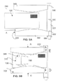
- FIG. 5A is a top view of an incoming mail air sampler according to an embodiment of the present application in a first position.
- FIG. 5B is a top view of an incoming mail air sampler according to an embodiment of the present application in a second position.
- FIG. 5C is a top view of an incoming mail air sampler according to an embodiment of the present application in a third position.
- FIG. 5D is a top view of an incoming mail air sampler according to an embodiment of the present application in a fourth position.
- FIG. 6 is a perspective side view of an incoming mail air sampler according to an embodiment of the present application.
- FIG. 7 is a top view of a flattener according to an embodiment of the present application.
- FIG. 8 is a flowchart showing a process for detecting contaminated mail according to an embodiment of the present application.
- Anthrax has been introduced into the mail system as a biological weapon. Similarly, other hazardous biological or chemical materials might be similarly transported in a mail system. Such criminal and terrorist activity provides a threat of cross contamination if entered into the mail-processing stream.
- the present application describes embodiments of a system and method for detecting contaminated mail at the point of entry to keep it from entering the mail stream.
- USPS United States Postal Service
- the United States Postal Service (USPS) is referred to describe illustrative examples of a mail streams.
- the embodiments are illustrative and where alternative elements are described, they are understood to fully describe alternative embodiments without repeating common elements of other appropriate embodiments.
- incoming mail receptacle There are many incoming mail receptacle in use. For example, in the United States, the USPS makes available many incoming mailboxes situated on public streets. Additionally, some public mailboxes are designed to be accessible to a driver such that the driver does not have to leave the car to place mail into the mailbox. Furthermore, USPS Post Offices utilize mail slots to receive incoming mail. Similarly, apartment buildings often have a group outgoing mail receptacle. Mail carriers also pick up mail from residential mailboxes. There are also several types of office mail delivery outgoing mailboxes in use. A department typically has a mail stop area with a drop off area for mail to be delivered to a post office.
- Anthrax bacteria bacillus antrhracis
- Typical paper has pores that average 10 microns in diameter, while the width of a typical human hair is around 90 microns.
- Letter envelopes are often not hermetically sealed and may be porous such that anthrax may pass through the envelope. Accordingly, anthrax and other biological and chemical hazards may escape from envelopes to contaminate mail-processing equipment that may cross contaminate other letters.
- a sealed letter may not confine any enclosed anthrax to that particular letter and anthrax or other hazards may adhere to mail pieces.
- the relative anonymity of required markings on a letter present an inherent difficulty in identifying suspect letters to be scrutinized on the basis of the identity of the sender, receiver, type of markings used or postage.
- a prior art mail process is shown.
- a mail system user will prepare a mail piece such as a letter or a card.
- the user may place postage on the mail piece using a stamp, meter indicia or permit indicia in step 16 .
- the user then places the mail piece in an incoming mail receptacle such as an incoming USPS mailbox in step 20 .
- a user may also place postage on the mail piece in step 17 and then bring the mail piece to a USPS clerk in step 22 .
- a postal worker will collect mail pieces from the mailbox in a sack in step 30 and bring them to a USPS facility for an initial cull in step 40 .
- the mail pieces will then go through an AFCS process in step 42 to scan, OCR and code the mail pieces. If the mail piece could not be processed by the AFCS, a manual sort and encode is performed in step 44 . Thereafter in step 46 the AFCS and manual streams merge for automatic sort processing in step 46 . Thereafter the sorted mail is transported in step 50 to a USPS facility where it is resorted for a letter carried in step 52 and delivered to the recipient in step 60 .
- the user may prepare a flat or parcel in step 14 .
- the user may place postage on the mail piece in steps 16 or 17 , but may pay for postage applied by a clerk in step 18 .
- the flat or parcel may be placed in a mailbox in step 20 as described above, or may be brought to a USPS clerk in step 22 for processing into a incoming tray in step 32 .
- the mail piece is then placed in the initial cull in step 40 and processed as above.
- a prior art mail process for presorted bulk mail is shown.
- a mail system user prepares presorted mail pieces such as letter and cards.
- the user may prepare presorted flats or parcels in step 15 , the mail pieces are prepared with permit indicia or metered indicia with the required presort discount documentation in step 19 .
- the mail pieces are brought to the USPS business mail acceptance dock with the required documentation in step 33 to be placed in processing trays, sacks and skids in step 35 .
- the mail is placed directly in transport in step 50 for later resort and delivery.
- Envelope 100 is marked with a label 111 for a return address and a label 114 for a destination address. A postage indicia 116 is also shown.
- FIG. 3B an envelope is shown. Envelope 100 is directly marked with return address 112 and destination address 115 with postage indicia 117 .
- the envelope is a number 10 paper envelope.
- the flap (not shown has a strip of glue that covers much of the perimeter of the inside flap.
- the present application describes embodiments that process envelopes that are not hermetically sealed.
- the examination and study of many envelopes suggests that even very well sealed envelopes have four corners that are not hermetically sealed.
- the openings typically vary between 3 and 10 mm. Squeezing the edges of a flat envelope will deform the flat envelope into a pillow shape with air in the pillowed area.
- the envelope thus shaped is somewhat like a bellows such that maintaining the force on the edges while squeezing the pillowed are will force air out of the openings. If the pillow is flattened from one direction, a majority of the escaping air will come from one side of the envelope.
- the force applied to the pillowed area and the edges can be monitored along with any feedback to prevent crushing the envelope.
- various forms of mail include many forms of correspondence including bills, advertisements, government correspondence, periodicals and parcels.
- Incoming mailbox 200 has a front panel 201 containing a slot 208 for receptacle identification cards and a mail slot 207 for depositing mail, a top panel 206 , side panels (not shown) and a back panel 203 having a door 204 for access to life-harming materials, and a door 205 for access to non-life-harming materials.
- Receptacle 200 has a sampling chamber 210 that contains an image scanner 211 and a transport mechanism 212 . When mail piece 100 (FIG. 5) is deposited face up in slot 207 , mail piece 100 will enter sampler chamber 210 .
- Receptacle controller 213 controls the hazard detection process and the hazard notification process. Controller 213 is powered by power source 202 and is connected to communications device 220 . Communications device 220 includes a cellular data modem. Alternatively any wired or wireless communications device may be utilized. The control and power connections for such a system are well known and not described in detail. Power is preferably supplied by a battery and solar power array.
- An external door 219 with handle is provided to allow access to mail opening 207 .
- a second door (not shown) capable of creating an interior hermetic seal connected to the controller and provided to lock the mailbox in case a hazard is detected.
- An internal door 215 hermetically seals chamber 210 during the test and then after a successful test, it opens to allow the mail piece to enter the inner chamber 214 .
- Scale 238 detects the presence and optionally the weight of the mail pieces in the inner chamber. Alternatively an optical sensor may be utilized.
- the sampler described below will provide an air sample from a mail piece through vacuum tube 231 to sensors 232 using vacuum system 233 and filter 234 to vent the vacuum outside the mailbox.
- sensors 232 provide a near real time test that is performed before the mail piece is accepted and before the mailbox is cleared to receive another mail piece at the input 207 .
- Additional sensors 236 , 237 provide additional test having relatively longer test times.
- the mailbox stops accepting mail pieces at a predetermined time before a scheduled pick up so that the slower sensors 236 , 237 can provide an adequate test. For example, if there is a scheduled pick up at 8 o'clock in the evening, the mailbox will stop accepting mail 30 minutes before to allow a PCR based DNA test of collected samples.
- the mailbox is preferably hermetically sealed to contain any detected hazards and completely opaque to visible light and other near spectrums including Ultra Violet (UV) in order to prevent disruption of the sensor.
- UV Ultra Violet
- Sensors 232 include fast response sensors. Sensors 232 include an Endospore Detection System available from Ocean Optics of Dunedin, Fla. In an alternative, sensors 232 may include a laser-acoustic sensor available from the Office of Naval Research. Similarly, sensors 232 may include an ultraviolet fluorescence bacteria detector from Sandia National Laboratories described in Proc. SPIE Vol. 2366, p. 1471-153, incorporated by reference.
- Controller 213 will shut down the mailbox and close upon a positive test. The controller 213 will then use communications device 220 to alert a response team.
- Sensors 232 preferably include a mass spectrometer detector for detecting explosives, narcotics, chemical and biological agents as potential hazards.
- Sensors 232 include a UV radiation source and a fluorometer to detect fluorescent radiation in the air sample.
- the sampled air is forced into distilled water for 45 seconds to extract any dipicolinic acid present, followed by chelation with terbium and tested for phosphorescence.
- Sensors 236 include relatively slow test systems including a 30 minute test PCR based detection system such as that available from Cepheid. The sampled air is divided via sampling tubes into the reagent chambers of the test kit and processed. Alternatively, a DNA test system available from Lawrence Livermore Laboratory is utilized. Alternatively, a system from the Office of Naval Research utilizing lasers and acoustic sensors is utilized.
- the sampled air is forced into water and tested with water test systems such as those available from Sandia National Laboratories of Albuquerque, N.Mex.
- Sensors 237 include relatively slow test systems including a toxic agent sniff sensor available from Sandia National Laboratories of Albuquerque, N.Mex. and used for testing for toxins in water supplies.
- a toxic agent sniff sensor available from Sandia National Laboratories of Albuquerque, N.Mex. and used for testing for toxins in water supplies.
- an Immunoaffinity-based phosphorescent sensor is utilized as described in Proc. SPIE Vol. 3913, p.204-14, incorporated by reference.
- a system available from Egea Biosciences of San Diego, Calif. is used. It was developed under a DARPA contract using a DNA-chip and non-repeating markers as identifiers of biological hazards.
- a system available from Cellomics, Inc. of Pittsburgh, Pa. using living cell technology is utilized.
- Sensors 232 include ion mobility spectrometer sensors available from Sandia National Laboratories of Albuquerque, N.Mex. for detecting bombs.
- the sampler system may be utilized in other devices that may be utilized at different stages of the mail flow process.
- Sensors 232 , 236 and 237 are described as plural sensors, however, one sensor may be used for each.
- each sensor device described may be preferred for a sensor in device 232 , 236 or 237 , but may be used in any or all of the sensors 232 , 236 and 237 .
- An additional embodiment may use only one of sensors 232 , 236 , 237 or a combination of two or more of them.
- a first position of the extractor includes a first envelope deforming block 320 and a second envelope deforming block 322 configured to receive a mail piece in a flat orientation that is not raised on edge.
- the blocks 320 , 322 are shown in the open position.
- the mail piece is fed into the sample extractor using mail piece handling equipment such as a continuous belt driven by an electric motor. Alternatively rollers may be used. Equipment for moving mail pieces is well known and will not be described in detail.
- the mail piece, number 10 envelope 100 is fed into sample extractor 300 in direction A.
- Sample extractor 300 includes a vacuum collector 332 having openings 330 and vacuum tube 334 .
- FIG. 5B a second position of the extractor is shown.
- a sensor (not shown) determines that the envelope 100 is in place
- block 320 is activated and forced in direction B and block 322 is forced in direction C such that edge 324 deforms envelope 100 .
- the envelope 100 will form a pillowed area 150 .
- Flattener 340 is a squeeze roller rubber wheel on shaft 342 that is lowered into position over envelope 100 at the edge closest the input of mailbox 200 .
- the vacuum may begin at ports 330 as air may flow in directions E, F when at this position.
- FIG. 5C a third position of the extractor is shown.
- the flattener 340 is rolled forward in direction A to squeeze the air out of pillowed area 150 while the vacuum collection ports 330 collect air forced out at E, F.
- the blocks 320 , 322 are stopped and the squeeze roller 340 is started when a light sensor (not shown) indicates a sufficient amount of pillowing.
- the squeeze roller 340 is equipped with a feedback sensor to determine if a hermetically sealed envelope is present.
- the force required to deflate the pillowed area 150 should decrease if the envelope 100 is not hermetically sealed. In such a case, the detected hermetically sealed envelope is segregated for further scrutiny.
- a vacuum is applied to all or part of the bottom of the envelope to hold down the bottom side. Any air picked up by the vacuum is fed through the detector, as the envelope may be porous to a hazardous material.
- a fourth position of the extractor is shown.
- the blocks 320 , 322 are returned to the start position to release the pillowing tension on the envelope 100 .
- the flattener 340 is rolled backward in direction B to re-flatten the envelope.
- the envelope is fed forward if the test passes and the flattener is then returned to a start position for the next envelope.
- the squeeze roller does not flatten the envelope o the return path B, but is lifted off the envelope.
- only one envelope-deforming block is movable.
- the mail piece is fed on edge such that gravity will aid registration of the mail piece and collection of the sample.
- the width of the incoming mail piece is measured to set the position and distance between blocks 320 , 322 in a snug open position before moving them into a pillowing position.
- the width measurement is performed using a series of light sensors in a row at the opening 207 of the mailbox 200 .
- flattening plate 370 is forced down in direction G by link 374 and force measurement device 372 , followed by force on link 376 and force measurement device 378 to flatten pillowed area 150 .
- rollers 310 ′ feed the envelope 100 forward into blocks 320 , 322 .
- Flattener 340 is independently connected with links 346 such that any one, all, or combination of rollers 340 , 342 , 244 may be lowed and rolled over a mail piece.
- a brush or scraper is used to sample a surface or both sides of a mail piece.
- a source of forced air such as a fan may be used to move the sample closer to the vacuum sampling holes.
- step 410 the process detects the presence of a mail piece.
- step 420 the process imports the mail piece into the segregated incoming mail sampler.
- step 430 the process collects an air sample.
- step 440 the process tests the air sample for hazards.
- step 450 the process includes a decision step to decide is a hazard is present. If a hazard is present, the process provides a hazard indication in step 470 and then ends. If no hazard is present, the process transports the mail piece to the collection chamber in step 460 and then ends.
- Position and presence sensors are well known and not described in detail.
- force sensors and feedback loops are well known and not described in detail.
- Controllers and timers are well known and not described in detail. The processes described may be performed in hardware, firmware, in software on a general-purpose processor or combination thereof.
- the controller may be a Pentium III mobile processor with support circuits and devices, but may include another processor and may be re-configurable and may be networked via a wired or wireless communications channel.
- USPS clerks may use the devices described above at a post office counter.
- several units may be located in close proximity and may share common parts other than the actual envelope feeder.
- a common controller may service four units that are networked.
- a common vacuum source and a common power source may be shared.
- a mailbox 200 includes an incoming chute that directs mail into a plastic bag that the postal worker can hermetically seal for transport to a safe mail handling facility to test for hazards.
- the mailbox identifier can be placed on the plastic bag.
- the mailbox contains a store of plastic bags lining the receptacle and a heat applicator to hermetically seal the bags before a postal worker picks up the bag.
- the incoming mail mailbox includes a parcel receptacle that contains a holding area that is hermetically sealed and segregated from the letter holding area.
- Current USPS requirements state that parcels weighing over one pound cannot be placed in incoming letter boxes.
- Another portion of the scale 238 may be utilized to ensure compliance.
- the letter puffer or air sampler 300 includes a feedback system to determine if the letter is hermetically sealed.
- the puffer sensor tests the letter. If the feedback system determines that a letter is hermetically sealed, it is passed through an UV-C ultraviolet surface decontamination system and segregated in a hermetically sealed envelope bin.
- the air sampler includes a segmented skewer that is utilized to penetrate the mail piece.
- One opening forces air into the envelope at a first location and a second opening introduces a vacuum to remove a sample of air from the envelope.
- two hollow tubes are inserted in the envelope openings to force in air and remove a sample, respectively.
- the scanner is placed in front of the envelope feed path to scan the top of the envelope.
- the scanner is used to determine if the envelope is inserted face up and includes postage. If the envelope is upside down, it is ejected. If the envelope is inserted in the correct orientation, it is scanned and fed to the detector stage.
- the scanner is used to scan the entire face of the document.
Abstract
A method and system for detecting chemical or biological hazards in items is provided. An incoming mail mailbox includes a sampler to sample air from a letter that is tested using a first sensor and then placed in a receptacle having an environment that is tested using a second sensor.
Description
This application is related to commonly assigned, U.S. patent application Ser. No.: 09/683,380, filed on even date herewith, entitled “METHOD AND SYSTEM FOR DETECTING BIOLOGICAL AND CHEMICAL HAZARDS IN NETWORKED INCOMING MAILBOXES,” in the name of Ronald P. Sansone, Robert A. Cordery and Karin A. Russo, the disclosure of which is hereby incorporated by reference in its entirety. This application is related to commonly assigned, U.S. patent application Ser. No.: 09/683,381, filed on even date herewith, entitled “METHOD AND SYSTEM FOR NOTIFYING MAIL USERS OF MAIL PIECE CONTAMINATION,” in the name of Ronald P. Sansone, Robert A. Cordery and Karin A. Russo, the disclosure of which is hereby incorporated by reference in its entirety.
The embodiments described herein relate generally to detecting hazards in mail and more specifically to systems and methods for detecting and containing contaminated mail in an incoming mail mailbox.
The United States Postal Service (USPS) provides a service of mail piece reception, sorting and delivery to national addresses and international postal streams. The USPS processes approximately 200 billion domestic letters per year. The USPS also processes parcels. Similarly, other courier services also exist that process letters and parcels.
Anthrax spores have been detected on mail pieces, mail-handling equipment and in or near areas where certain mail pieces that likely contained anthrax were handled. Several people that were in such areas have contracted anthrax disease. These attacks pose a danger of infection that may be lethal to those in affected areas. Additionally, there is no readily available warning system to provide an early warning that a mail piece contains anthrax spores. Certain members of the general population may fear receiving and handling mail due to the threat of mail terrorism.
Anthrax is a biological agent that has apparently been placed in the U.S. postal delivery system in mail pieces that could be considered camouflaged as ordinary mail because they were not properly marked or properly contained, as a dangerous biological agent should be. The person placing such mail in the mail system had the apparent sole purpose of delivering the Anthrax as a biological weapon to kill the immediate victims and terrorize others who use the postal system. The Anthrax has apparently been transported in spore form and in such a small form as to enable it to float in the air. The disease known as Anthrax disease is caused by the bacterium Bacillus anthracis that is known as Anthrax. Anthrax is rod-shaped, and relatively large for a bacterium at 1 to 10 μm in length.
The disease may be manifested as pulmonary anthrax or inhalation anthrax when a sufficient amount of Anthrax is inhaled. The disease may be manifested as intestinal anthrax when ingested in too great a quantity. The disease may be manifested as cutaneous anthrax that is typically found when an open wound or sore of a person has been exposed to Anthrax.
There are dozens of biological and chemical substances that are potential hazards if placed in the mail stream. Additionally, explosive devices have been sent in the mails in order to harm recipients.
In one embodiment, an incoming mail receptacle device includes a biological contamination detection system to determine if mail inserted into the receptacle is contaminated. An air sample is collected from an incoming mail piece and then processed though a hazard detector to determine if the mail piece is contaminated.
FIG. 1 is a flow chart showing a prior art postal delivery process.
FIG. 2 is a flow chart showing a prior art postal delivery process.
FIG. 3A is a top view of a mail piece.
FIG. 3B is a top view of a mail piece.
FIG. 4 is a perspective cutaway view of an incoming mail receptacle according to an embodiment of the present application.
FIG. 5A is a top view of an incoming mail air sampler according to an embodiment of the present application in a first position.
FIG. 5B is a top view of an incoming mail air sampler according to an embodiment of the present application in a second position.
FIG. 5C is a top view of an incoming mail air sampler according to an embodiment of the present application in a third position.
FIG. 5D is a top view of an incoming mail air sampler according to an embodiment of the present application in a fourth position.
FIG. 6 is a perspective side view of an incoming mail air sampler according to an embodiment of the present application.
FIG. 7 is a top view of a flattener according to an embodiment of the present application.
FIG. 8 is a flowchart showing a process for detecting contaminated mail according to an embodiment of the present application.
Anthrax has been introduced into the mail system as a biological weapon. Similarly, other hazardous biological or chemical materials might be similarly transported in a mail system. Such criminal and terrorist activity provides a threat of cross contamination if entered into the mail-processing stream.
The present application describes embodiments of a system and method for detecting contaminated mail at the point of entry to keep it from entering the mail stream. The United States Postal Service (USPS) is referred to describe illustrative examples of a mail streams. The embodiments are illustrative and where alternative elements are described, they are understood to fully describe alternative embodiments without repeating common elements of other appropriate embodiments.
There are many incoming mail receptacle in use. For example, in the United States, the USPS makes available many incoming mailboxes situated on public streets. Additionally, some public mailboxes are designed to be accessible to a driver such that the driver does not have to leave the car to place mail into the mailbox. Furthermore, USPS Post Offices utilize mail slots to receive incoming mail. Similarly, apartment buildings often have a group outgoing mail receptacle. Mail carriers also pick up mail from residential mailboxes. There are also several types of office mail delivery outgoing mailboxes in use. A department typically has a mail stop area with a drop off area for mail to be delivered to a post office.
Anthrax bacteria, bacillus antrhracis, has been described as a very large, Gram-positive, spore-forming rod of 1-1.2 micron in width and 3-5 micron in length that form oval spores located centrally in a non-swollen sporangium. Typical paper has pores that average 10 microns in diameter, while the width of a typical human hair is around 90 microns. Letter envelopes are often not hermetically sealed and may be porous such that anthrax may pass through the envelope. Accordingly, anthrax and other biological and chemical hazards may escape from envelopes to contaminate mail-processing equipment that may cross contaminate other letters. Therefore, a sealed letter may not confine any enclosed anthrax to that particular letter and anthrax or other hazards may adhere to mail pieces. Some people advocate scrutinizing mail with excess postage or handwritten addresses. However, the relative anonymity of required markings on a letter present an inherent difficulty in identifying suspect letters to be scrutinized on the basis of the identity of the sender, receiver, type of markings used or postage.
Referring to FIG. 1, a prior art mail process is shown. In step 12, a mail system user will prepare a mail piece such as a letter or a card. The user may place postage on the mail piece using a stamp, meter indicia or permit indicia in step 16. The user then places the mail piece in an incoming mail receptacle such as an incoming USPS mailbox in step 20. A user may also place postage on the mail piece in step 17 and then bring the mail piece to a USPS clerk in step 22. A postal worker will collect mail pieces from the mailbox in a sack in step 30 and bring them to a USPS facility for an initial cull in step 40. The mail pieces will then go through an AFCS process in step 42 to scan, OCR and code the mail pieces. If the mail piece could not be processed by the AFCS, a manual sort and encode is performed in step 44. Thereafter in step 46 the AFCS and manual streams merge for automatic sort processing in step 46. Thereafter the sorted mail is transported in step 50 to a USPS facility where it is resorted for a letter carried in step 52 and delivered to the recipient in step 60. The user may prepare a flat or parcel in step 14. The user may place postage on the mail piece in steps 16 or 17, but may pay for postage applied by a clerk in step 18. The flat or parcel may be placed in a mailbox in step 20 as described above, or may be brought to a USPS clerk in step 22 for processing into a incoming tray in step 32. The mail piece is then placed in the initial cull in step 40 and processed as above.
Referring to FIG. 2, a prior art mail process for presorted bulk mail is shown. In step 11, a mail system user prepares presorted mail pieces such as letter and cards. The user may prepare presorted flats or parcels in step 15, the mail pieces are prepared with permit indicia or metered indicia with the required presort discount documentation in step 19. The mail pieces are brought to the USPS business mail acceptance dock with the required documentation in step 33 to be placed in processing trays, sacks and skids in step 35. As shown in FIG. 2, the mail is placed directly in transport in step 50 for later resort and delivery.
Referring to FIG. 3A, an envelope is shown. Envelope 100 is marked with a label 111 for a return address and a label 114 for a destination address. A postage indicia 116 is also shown. Referring to FIG. 3B, an envelope is shown. Envelope 100 is directly marked with return address 112 and destination address 115 with postage indicia 117. The envelope is a number 10 paper envelope. The flap (not shown has a strip of glue that covers much of the perimeter of the inside flap.
The present application describes embodiments that process envelopes that are not hermetically sealed. The examination and study of many envelopes suggests that even very well sealed envelopes have four corners that are not hermetically sealed. The openings typically vary between 3 and 10 mm. Squeezing the edges of a flat envelope will deform the flat envelope into a pillow shape with air in the pillowed area. The envelope thus shaped is somewhat like a bellows such that maintaining the force on the edges while squeezing the pillowed are will force air out of the openings. If the pillow is flattened from one direction, a majority of the escaping air will come from one side of the envelope.
The force applied to the pillowed area and the edges can be monitored along with any feedback to prevent crushing the envelope.
As can be appreciated, various forms of mail include many forms of correspondence including bills, advertisements, government correspondence, periodicals and parcels.
Referring to FIG. 4, an incoming mail receptacle with hazard detector is described. Incoming mailbox 200 has a front panel 201 containing a slot 208 for receptacle identification cards and a mail slot 207 for depositing mail, a top panel 206, side panels (not shown) and a back panel 203 having a door 204 for access to life-harming materials, and a door 205 for access to non-life-harming materials. Receptacle 200 has a sampling chamber 210 that contains an image scanner 211 and a transport mechanism 212. When mail piece 100 (FIG. 5) is deposited face up in slot 207, mail piece 100 will enter sampler chamber 210. The face of mail piece 100 will be scanned and read by scanner 211 while being moved by transport 212. Receptacle controller 213 controls the hazard detection process and the hazard notification process. Controller 213 is powered by power source 202 and is connected to communications device 220. Communications device 220 includes a cellular data modem. Alternatively any wired or wireless communications device may be utilized. The control and power connections for such a system are well known and not described in detail. Power is preferably supplied by a battery and solar power array.
An external door 219 with handle is provided to allow access to mail opening 207. A second door (not shown) capable of creating an interior hermetic seal connected to the controller and provided to lock the mailbox in case a hazard is detected. An internal door 215 hermetically seals chamber 210 during the test and then after a successful test, it opens to allow the mail piece to enter the inner chamber 214. Scale 238 detects the presence and optionally the weight of the mail pieces in the inner chamber. Alternatively an optical sensor may be utilized.
The sampler described below will provide an air sample from a mail piece through vacuum tube 231 to sensors 232 using vacuum system 233 and filter 234 to vent the vacuum outside the mailbox. As described below, sensors 232 provide a near real time test that is performed before the mail piece is accepted and before the mailbox is cleared to receive another mail piece at the input 207. Additional sensors 236, 237 provide additional test having relatively longer test times. In an alternative embodiment, the mailbox stops accepting mail pieces at a predetermined time before a scheduled pick up so that the slower sensors 236, 237 can provide an adequate test. For example, if there is a scheduled pick up at 8 o'clock in the evening, the mailbox will stop accepting mail 30 minutes before to allow a PCR based DNA test of collected samples.
The mailbox is preferably hermetically sealed to contain any detected hazards and completely opaque to visible light and other near spectrums including Ultra Violet (UV) in order to prevent disruption of the sensor.
In an alternative embodiment, Sensors 232 preferably include a mass spectrometer detector for detecting explosives, narcotics, chemical and biological agents as potential hazards. Sensors 232 include a UV radiation source and a fluorometer to detect fluorescent radiation in the air sample.
In an alternative embodiment, the sampled air is forced into distilled water for 45 seconds to extract any dipicolinic acid present, followed by chelation with terbium and tested for phosphorescence.
Alternatively, the sampled air is forced into water and tested with water test systems such as those available from Sandia National Laboratories of Albuquerque, N.Mex.
In an alternative embodiment, Sensors 232 include ion mobility spectrometer sensors available from Sandia National Laboratories of Albuquerque, N.Mex. for detecting bombs.
The sampler system may be utilized in other devices that may be utilized at different stages of the mail flow process. Sensors 232, 236 and 237 are described as plural sensors, however, one sensor may be used for each. Furthermore, each sensor device described may be preferred for a sensor in device 232, 236 or 237, but may be used in any or all of the sensors 232, 236 and 237. An additional embodiment may use only one of sensors 232, 236, 237 or a combination of two or more of them.
Referring to FIGS. 5A-5D, the sample extractor 300 is described. Referring to FIG. 5A, a first position of the extractor includes a first envelope deforming block 320 and a second envelope deforming block 322 configured to receive a mail piece in a flat orientation that is not raised on edge. The blocks 320, 322 are shown in the open position. The mail piece is fed into the sample extractor using mail piece handling equipment such as a continuous belt driven by an electric motor. Alternatively rollers may be used. Equipment for moving mail pieces is well known and will not be described in detail. The mail piece, number 10 envelope 100 is fed into sample extractor 300 in direction A. Sample extractor 300 includes a vacuum collector 332 having openings 330 and vacuum tube 334.
Referring to FIG. 5B, a second position of the extractor is shown. When a sensor (not shown) determines that the envelope 100 is in place, block 320 is activated and forced in direction B and block 322 is forced in direction C such that edge 324 deforms envelope 100. The envelope 100 will form a pillowed area 150. Flattener 340 is a squeeze roller rubber wheel on shaft 342 that is lowered into position over envelope 100 at the edge closest the input of mailbox 200. The vacuum may begin at ports 330 as air may flow in directions E, F when at this position.
Referring to FIG. 5C, a third position of the extractor is shown. The flattener 340 is rolled forward in direction A to squeeze the air out of pillowed area 150 while the vacuum collection ports 330 collect air forced out at E, F.
In an alternative embodiment, the blocks 320, 322 are stopped and the squeeze roller 340 is started when a light sensor (not shown) indicates a sufficient amount of pillowing.
In a further alternative embodiment, the squeeze roller 340 is equipped with a feedback sensor to determine if a hermetically sealed envelope is present. The force required to deflate the pillowed area 150 should decrease if the envelope 100 is not hermetically sealed. In such a case, the detected hermetically sealed envelope is segregated for further scrutiny.
In another alternative embodiment, a vacuum is applied to all or part of the bottom of the envelope to hold down the bottom side. Any air picked up by the vacuum is fed through the detector, as the envelope may be porous to a hazardous material.
Referring to FIG. 5D, a fourth position of the extractor is shown. The blocks 320, 322 are returned to the start position to release the pillowing tension on the envelope 100. The flattener 340 is rolled backward in direction B to re-flatten the envelope. The envelope is fed forward if the test passes and the flattener is then returned to a start position for the next envelope. In an alternative, the squeeze roller does not flatten the envelope o the return path B, but is lifted off the envelope.
In an alternative embodiment, only one envelope-deforming block is movable. In another alternative, the mail piece is fed on edge such that gravity will aid registration of the mail piece and collection of the sample.
In a further alternative embodiment, the width of the incoming mail piece is measured to set the position and distance between blocks 320, 322 in a snug open position before moving them into a pillowing position. The width measurement is performed using a series of light sensors in a row at the opening 207 of the mailbox 200.
Referring to FIG. 6, an alternative flattener is shown. In this embodiment, flattening plate 370 is forced down in direction G by link 374 and force measurement device 372, followed by force on link 376 and force measurement device 378 to flatten pillowed area 150. In this embodiment, rollers 310′ feed the envelope 100 forward into blocks 320, 322.
Referring to FIG. 7, an alternative flattener is shown to accommodate varying width mail pieces. Flattener 340 is independently connected with links 346 such that any one, all, or combination of rollers 340, 342, 244 may be lowed and rolled over a mail piece.
In another embodiment, a brush or scraper is used to sample a surface or both sides of a mail piece. A source of forced air such as a fan may be used to move the sample closer to the vacuum sampling holes.
Referring to FIG. 8, a process for detecting hazardous mail is described. In step 410, the process detects the presence of a mail piece. In step 420, the process imports the mail piece into the segregated incoming mail sampler. In step 430, the process collects an air sample. In step 440, the process tests the air sample for hazards. In step 450, the process includes a decision step to decide is a hazard is present. If a hazard is present, the process provides a hazard indication in step 470 and then ends. If no hazard is present, the process transports the mail piece to the collection chamber in step 460 and then ends.
Position and presence sensors are well known and not described in detail. Similarly, force sensors and feedback loops are well known and not described in detail.
Controllers and timers are well known and not described in detail. The processes described may be performed in hardware, firmware, in software on a general-purpose processor or combination thereof. The controller may be a Pentium III mobile processor with support circuits and devices, but may include another processor and may be re-configurable and may be networked via a wired or wireless communications channel.
In an alternative embodiment, USPS clerks may use the devices described above at a post office counter. In such a system, several units may be located in close proximity and may share common parts other than the actual envelope feeder. In one embodiment, a common controller may service four units that are networked. Similarly, a common vacuum source and a common power source may be shared.
In an alternative embodiment, a mailbox 200 includes an incoming chute that directs mail into a plastic bag that the postal worker can hermetically seal for transport to a safe mail handling facility to test for hazards. The mailbox identifier can be placed on the plastic bag. In another embodiment, the mailbox contains a store of plastic bags lining the receptacle and a heat applicator to hermetically seal the bags before a postal worker picks up the bag.
In an alternative embodiment, the incoming mail mailbox includes a parcel receptacle that contains a holding area that is hermetically sealed and segregated from the letter holding area. Current USPS requirements state that parcels weighing over one pound cannot be placed in incoming letter boxes. Another portion of the scale 238 may be utilized to ensure compliance.
In an alternative embodiment, the letter puffer or air sampler 300 includes a feedback system to determine if the letter is hermetically sealed. The puffer sensor tests the letter. If the feedback system determines that a letter is hermetically sealed, it is passed through an UV-C ultraviolet surface decontamination system and segregated in a hermetically sealed envelope bin.
In an alternative embodiment, the air sampler includes a segmented skewer that is utilized to penetrate the mail piece. One opening forces air into the envelope at a first location and a second opening introduces a vacuum to remove a sample of air from the envelope. In a further alternative, two hollow tubes are inserted in the envelope openings to force in air and remove a sample, respectively.
In an alternative embodiment, the scanner is placed in front of the envelope feed path to scan the top of the envelope. The scanner is used to determine if the envelope is inserted face up and includes postage. If the envelope is upside down, it is ejected. If the envelope is inserted in the correct orientation, it is scanned and fed to the detector stage.
In an alternative embodiment, the scanner is used to scan the entire face of the document.
The systems described above require electrical power. Power supplies are well known and not described in detail. A utility connection, a battery, solar power or other source of electricity may power the system.
The above specification describes system and methods for detecting hazards in mail. As can be appreciated, various combinations of the above detection systems may be utilized.
The described embodiments are illustrative and the above description may indicate to those skilled in the art additional ways in which the principles of this invention may be used without departing from the spirit of the invention. Accordingly the scope of the claims should not be limited by the particular embodiments described.
Claims (11)
1. An incoming mail receptacle for detecting hazards in a mail piece comprising:
a segregated incoming mail air sampler for collecting an air sample having an incoming mail opening and a lockable door for the opening;
a hazard detector to test the sample and for providing a hazard indication;
a transport mechanism for moving the mail piece from the air sampler into a collection chamber if no hazard is detected;
a hazard indicator connected to the hazard detector for alerting a user of a hazard; wherein the airsampler includes
a mail piece transport system for feeding a mail piece through the sampler;
a movable surface for applying force to an edge of the mail piece to form a pillow deformation in the mail piece; and
a flattener for flattening the pillow deformation to eject and collect an air sample from the mail piece.
2. The apparatus of claim 1 further comprising:
a controller connected to the air sampler, hazard detector, transport mechanism and hazard indicator for coordinating sample collection, hazard detection and hazard indication;
a vacuum system connected to the controller having a vacuum source for collecting the sample;
a filter connected to the vacuum system for filtering the exhaust from the vacuum source; and
a latch mechanism connected to the controller for locking the lockable door.
3. The apparatus of claim 1 further comprising:
a scale operatively connected to the collection chamber for detecting the presence of mail pieces.
4. The apparatus of claim 1 further comprising:
a communications device for remotely alerting the user of a hazard.
5. The apparatus of claim 4 wherein:
the communications device includes a cellular link.
6. The apparatus of claim 1 further comprising:
a fluorometer hazard detector and a DNA analysis hazard detector.
7. The apparatus of claim 1 further comprising:
a fluorometer hazard detector.
8. A mail piece air sampler comprising:
a mail piece transport system for feeding a mail piece through the sampler;
a movable surface for applying force to an edge of the mail piece to form a pillow deformation in the mail piece; and
a flattener for flattening the pillow deformation to eject and collect an air sample from the mail piece.
9. The apparatus of claim 8 , wherein
the mail piece transport system includes a continuous loop driven by an electric motor with a vacuum hold down system for holding a mail piece in place.
10. The apparatus of claim 8 , wherein
the flattener includes a plurality of wheels.
11. A method for detecting hazards in a mail piece using a incoming mail receptacle comprising a segregated incoming mail air sampler for collecting an air sample having an incoming mail opening and a lockable door for the opening, a hazard detector to test the sample and for providing a hazard indication, a transport mechanism for moving the mail piece into a collection chamber if no hazard is detected and a hazard indicator connected to the hazard detector for alerting a user of a hazard, comprising:
detecting the presence of a mail piece;
importing the mail piece into the segregated incoming mail sampler;
collecting the air sample;
testing the air sample for hazards;
transporting the mail piece to the collection chamber of no hazard is detected; and
providing a hazard indication if a hazard is detected,
wherein the air sampler includes a mall piece transport system for feeding a mail piece through the sampler;
a movable surface for applying force to an edge of the mail piece to form a pillow deformation in the mail piece; and
a flattener for flattening the pillow deformation to eject and collect an air sample from the mail piece.
Priority Applications (5)
| Application Number | Priority Date | Filing Date | Title |
|---|---|---|---|
| US09/683,379 US6613571B2 (en) | 2001-12-19 | 2001-12-19 | Method and system for detecting biological and chemical hazards in mail |
| DE60235724T DE60235724D1 (en) | 2001-12-19 | 2002-12-17 | SYSTEM AND METHOD FOR DETECTING DANGEROUS GOODS |
| PCT/US2002/040432 WO2003054778A1 (en) | 2001-12-19 | 2002-12-17 | Notifying mail users of mail piece contamination |
| AU2002360642A AU2002360642A1 (en) | 2001-12-19 | 2002-12-17 | Notifying mail users of mail piece contamination |
| EP02795915A EP1466293B1 (en) | 2001-12-19 | 2002-12-17 | System and method for detecting hazards in a mail piece |
Applications Claiming Priority (1)
| Application Number | Priority Date | Filing Date | Title |
|---|---|---|---|
| US09/683,379 US6613571B2 (en) | 2001-12-19 | 2001-12-19 | Method and system for detecting biological and chemical hazards in mail |
Publications (2)
| Publication Number | Publication Date |
|---|---|
| US20030113230A1 US20030113230A1 (en) | 2003-06-19 |
| US6613571B2 true US6613571B2 (en) | 2003-09-02 |
Family
ID=24743791
Family Applications (1)
| Application Number | Title | Priority Date | Filing Date |
|---|---|---|---|
| US09/683,379 Expired - Fee Related US6613571B2 (en) | 2001-12-19 | 2001-12-19 | Method and system for detecting biological and chemical hazards in mail |
Country Status (1)
| Country | Link |
|---|---|
| US (1) | US6613571B2 (en) |
Cited By (33)
| Publication number | Priority date | Publication date | Assignee | Title |
|---|---|---|---|---|
| US20030058099A1 (en) * | 2001-10-23 | 2003-03-27 | Lopez Steven W. | System and methods for detecting harmful agents within contents of mail |
| US20030079444A1 (en) * | 2001-10-31 | 2003-05-01 | Robotic Vision Systems, Inc. | Method and apparatus for flattening cover tape |
| US20030110145A1 (en) * | 2001-12-12 | 2003-06-12 | Pitney Bowes Incorporated | System for a recipient to determine whether or not they received non-life-harming materials |
| US20030110143A1 (en) * | 2001-12-12 | 2003-06-12 | Pitney Bowes Incorporated | System for accepting non harming mail at a receptacle |
| US20030110048A1 (en) * | 2001-12-12 | 2003-06-12 | Pitney Bowes Incorporated | Method and system for accepting non-toxic mail that has an indication of the mailer on the mail |
| US20030110135A1 (en) * | 2001-12-12 | 2003-06-12 | Pitney Bowes Incorporated | Method and system for accepting non-harming mail at a home or office |
| US20030113922A1 (en) * | 2001-12-19 | 2003-06-19 | Pitney Bowes Inc. | Method and system for detecting biological and chemical hazards in networked incoming mailboxes |
| US20030110946A1 (en) * | 2001-12-17 | 2003-06-19 | William R. Lehman | System and method for removing contaminates from the air in a mail-sorting room |
| US20030136203A1 (en) * | 2001-10-26 | 2003-07-24 | Yoon Sung Hoon | Package biochemical hazard and contraband detector |
| US20030194350A1 (en) * | 2002-04-11 | 2003-10-16 | Siemens Information And Communication Networks | Public health threat surveillance system |
| US20030196937A1 (en) * | 2002-04-17 | 2003-10-23 | Pitney Bowes Incorporated | Method and system for detection of contaminants in mail |
| US20040076544A1 (en) * | 2002-10-09 | 2004-04-22 | Hung Dao | Method and apparatus for scanning and sterilizing mail received at a drop box |
| US20040080414A1 (en) * | 2002-10-24 | 2004-04-29 | Harry Darty | Hazardous material mail collection point-of-use |
| US20040211923A1 (en) * | 2003-04-24 | 2004-10-28 | Bridges John H. | Anthrax remediation and response |
| US20040255701A1 (en) * | 2002-05-31 | 2004-12-23 | Strohmeyer James J. | Systems and methods for residue collection |
| US7006923B1 (en) | 2004-05-19 | 2006-02-28 | The United States Of America As Represented By The Secretary Of The Navy | Distributed biohazard surveillance system and apparatus for adaptive collection and particulate sampling |
| US20060083359A1 (en) * | 2004-10-16 | 2006-04-20 | Mukunya Alfred K | Apparatus for mail delivery notification and process for doing same |
| US7100422B2 (en) | 2002-05-31 | 2006-09-05 | Drs Sustainment Systems, Inc. | Systems and methods for residue collection with improved letter handling capability |
| US20060225522A1 (en) * | 2005-03-29 | 2006-10-12 | Lockheed Martin Corporation | Method and apparatus for sampling biological particles in an air flow |
| US20060291657A1 (en) * | 2005-05-03 | 2006-12-28 | Greg Benson | Trusted monitoring system and method |
| US20070210934A1 (en) * | 2004-05-04 | 2007-09-13 | Marrell Haney | Double barrel chemical seeking sidewinder gun devices |
| US20070241881A1 (en) * | 2006-04-05 | 2007-10-18 | Larry Golden | Multi sensor detection and lock disabling system |
| US20080217524A1 (en) * | 2006-10-26 | 2008-09-11 | Smiths Detection Inc. | Document sampler and method of sampling a document |
| US20080250845A1 (en) * | 2007-04-12 | 2008-10-16 | Eric Gregory Burroughs | Mail screening device |
| US20080264186A1 (en) * | 2004-12-30 | 2008-10-30 | Smiths Detection Inc. | Article scanner |
| US7459700B2 (en) | 2002-04-24 | 2008-12-02 | United States Postal Service | Anthrax remediation and response |
| US7485437B1 (en) * | 2002-11-15 | 2009-02-03 | The United States Of America As Represented By The Secretary Of The Army | Method for detecting bacterial endospores in a sealed container |
| US20090066489A1 (en) * | 2006-04-05 | 2009-03-12 | Larry Golden | Multi sensor detection, stall to stop and lock disabling system |
| US20100136586A1 (en) * | 2003-04-02 | 2010-06-03 | Caufield Page W | Method for the surveillance for biological, chemical and radiological agents |
| US20100297602A1 (en) * | 2004-12-29 | 2010-11-25 | Jones Jr Arthur T | Apparatus and method of contaminant detection |
| US8047053B2 (en) * | 2007-05-09 | 2011-11-01 | Icx Technologies, Inc. | Mail parcel screening using multiple detection technologies |
| USRE43891E1 (en) | 2006-04-05 | 2013-01-01 | Larry Golden | Multi sensor detection, stall to stop and lock disabling system |
| USRE43990E1 (en) | 2006-04-05 | 2013-02-12 | Larry Golden | Multi sensor detection, stall to stop and lock disabling system |
Families Citing this family (6)
| Publication number | Priority date | Publication date | Assignee | Title |
|---|---|---|---|---|
| US7085746B2 (en) * | 2001-12-19 | 2006-08-01 | Pitney Bowes Inc. | Method and system for notifying mail users of mail piece contamination |
| AU2003208933A1 (en) * | 2002-02-01 | 2003-09-02 | California Institute Of Technology | Methods and apparatus for assays of bacterial spores |
| AU2003234101A1 (en) * | 2002-04-16 | 2003-11-03 | The Johns Hopkins University | Apparatus and method for automated parcel screening |
| CN107595088A (en) * | 2017-09-28 | 2018-01-19 | 刘伟 | A kind of mailbox for carrying mail arrangement function |
| US11020501B1 (en) | 2018-02-20 | 2021-06-01 | Freestyle Partners, LLC | Handheld ultraviolet irradiation device having distance measurement system |
| CN115515651A (en) * | 2020-04-01 | 2022-12-23 | 自由风格合伙有限公司 | System and method for safe irradiation of pathogens |
Citations (1)
| Publication number | Priority date | Publication date | Assignee | Title |
|---|---|---|---|---|
| EP1063602A1 (en) | 1999-06-24 | 2000-12-27 | Pitney Bowes Inc. | System and method for automatic notification of upcoming delivery of a mail item |
Family Cites Families (8)
| Publication number | Priority date | Publication date | Assignee | Title |
|---|---|---|---|---|
| US5089395A (en) * | 1985-02-27 | 1992-02-18 | University Of Cincinnati | Viable microorganism detection by induced fluorescence |
| US5200626A (en) * | 1990-03-28 | 1993-04-06 | Martin Marietta Energy Systems, Inc. | Hidden explosives detector employing pulsed neutron and x-ray interrogation |
| US5440136A (en) * | 1994-06-17 | 1995-08-08 | Penetron, Inc. | Anisotropic neutron scatter method and apparatus |
| US5904752A (en) * | 1997-06-23 | 1999-05-18 | Skc, Inc. | Method for collecting airborne particles and microorganisms by their injection into a swirling air flow |
| US5902385A (en) * | 1997-06-23 | 1999-05-11 | Skc, Inc. | Swirling aerosol collector |
| US20030034874A1 (en) * | 1998-10-29 | 2003-02-20 | W. Stephen G. Mann | System or architecture for secure mail transport and verifiable delivery, or apparatus for mail security |
| US6887710B2 (en) * | 1998-11-13 | 2005-05-03 | Mesosystems Technology, Inc. | Robust system for screening mail for biological agents |
| US6754366B2 (en) * | 2001-03-27 | 2004-06-22 | Pitney Bowes Inc. | Method for determining if mail contains life harming materials |
-
2001
- 2001-12-19 US US09/683,379 patent/US6613571B2/en not_active Expired - Fee Related
Patent Citations (1)
| Publication number | Priority date | Publication date | Assignee | Title |
|---|---|---|---|---|
| EP1063602A1 (en) | 1999-06-24 | 2000-12-27 | Pitney Bowes Inc. | System and method for automatic notification of upcoming delivery of a mail item |
Non-Patent Citations (41)
| Title |
|---|
| "Anthrax Detectors ar coming", Office of Naval Research, Oct. 29, 2001, 1 page. |
| "Biosensors and Biochips for Environmental and Biomedical Applications", www.ornl.gov/virtual/biosensor, Dec. 4, 2001, 2 pages. |
| "Cellomics, Inc. Announces the Development of Biowarfare Detection Methods", Nov. 21, 2001, www.prnewswire.com, 1 page. |
| "Egea Awarded Second DARPA Contract to Fight Bioterrorism", Oct. 30, 2001, 1 page. |
| "Electronic Sniffer, Listen Hard and listen good if you want to name that smell", Dec. 19, 200, 1 page, www.newscientist.com. |
| "ID Mail Systems to Develop Mail Profiling System for in-bound Mail Centers Against Potential Threatening Mail", Oct. 18, 2001, 2 pages. |
| "Lambda Technologies'Variable Microwave Systems Adapted to "Zap' Bioterrorism Threat", Nov. 5, 2001, www.prnewswire.com, 2 pages. |
| "Mail Performation Paddle used during a Yellow Fever Epidemic", http://www.si.edu/postal/learnmore/paddle.html, Nov. 29, 2001, 2 pages. |
| "Mailrooms on Front Lines in Bioterrorism Fight", Oct. 15, 2001, The Wall Street Journal, 1 page. |
| "Mathematical model provides new tool to asses mail-bourne spread of anthrax" May 13, 2002, 2 pages. |
| "On a spot smaller than a dime, UB chemists print sensors that may detect hundreds of chemicals", Jan. 25, 2002, 2 pages. |
| "Sandia's soil and groundwater chemical "sniffer' may help protect the nation's water supply", Oct. 3, 2001, www.sandia.gov/media/NewsRel.NR2001/whtsniff.htm (4 pages). |
| "Sensors Detect Biological Weapons", www.photonics.com/content/Jan99/techWeapons.html, Jan. 1994, 4 pages. |
| "Simple and inexpensive, an artificial nose senses smell by seeing colors", Aug. 16, 2000, 1 page. |
| "Stickers warn of UV Radiation", May 23, 2000, 1 page. |
| "The bugs of war", Nature, vol. 411, May 17, 2001, 4 pages. |
| "The Classica Group Files Patent Application for its Method of Sterilization Against Anthra Bacteria Disseminated on or in Paper", Oct. 26, 2001, businesswire, 1 page. |
| "Two new Sandia "sniffers'expand law enforcement abilities to detect explosives and narcotics", Nov. 30, 1999, www.sandia.gov/media/NewsRel.NR1999/sniffers.htm (4 apges). |
| "UMAss chemist working on sensors that could eventually identify bioterror agents", Dec. 13, 2001, 2 pages. |
| "What is a Fluorometer?", Jul. 17, 2001, 1 page, http://response.restoration.noaa.gov/oilaids/SMART/SMARTtour/fluor.html. |
| "Lambda Technologies'Variable Microwave Systems Adapted to ‘Zap’ Bioterrorism Threat", Nov. 5, 2001, www.prnewswire.com, 2 pages. |
| "Sandia's soil and groundwater chemical ‘sniffer’ may help protect the nation's water supply", Oct. 3, 2001, www.sandia.gov/media/NewsRel.NR2001/whtsniff.htm (4 pages). |
| "Two new Sandia ‘sniffers’expand law enforcement abilities to detect explosives and narcotics", Nov. 30, 1999, www.sandia.gov/media/NewsRel.NR1999/sniffers.htm (4 apges). |
| Aston, C., "Biological Warfare Canaries", IEEE Spectrum, Oct. 2001, 6 pages. |
| Cao, et al., DNA Nanoparticle Assembly and Diagnostics, Dec. 4, 2001, 2 pages. |
| E-nose noses out mines, Office of Naval Research, Apr. 17, 2001, 1 page. |
| Gordon, M., "Companies accused of Anthrax Fraud", Nov. 15, 2001, 1 page. |
| Hargis, et al., "Ultraviolet fluorescence identification of protein, DNA and bacteria", abstract Feb. 1995, 1 page. |
| Hohnson-Winegar, A., et al., "The DoD Biological Detection Program, NDIA Roundtable Discussions", Oct. 24, 2000, 27 pages. |
| Introduction to Fluorescense Techniques with bibliography, Dec. 4, 2001, www.probes.com/handbook, 9 pages. |
| McMillan, "Point-of-care Real Time Molecular Detection of Infectious Agents" May 20, 2001, 2 pages. |
| Meserve, J., "Feds, industry rush to make cheap biohazard detectors", Nov. 1, 2001, 1 page. |
| Murray, C., Biodetectors aim to broaden search for anthrax bacteria, Oct. 15, 2001, 5 pages. |
| Ocean Optics Brochure, Endospore Detection, Dec. 5, 2001, www.oceanoptics.com, 4 pages. |
| Ocean Optics Portable Endoscope Detection System Offers Real-time Antrax Screening, Nov. 15, 2001, 1 page. |
| Pinnick, R.G., et al., "Real-time Measurement of Fluorescence Spectra from Single Airborne Biological Particles", 1999, 32 pages. |
| Scholl, et al., "Immunoaffinity-based phosphorescent sensor platform for the detection of bacterial spores", abstract Apr. 2000, 1 page. |
| Shanker, M.S., "Instant anthrax detector developed in Hyderabad", Nov. 5, 2001, 1 page. |
| SKC BioSampler brochure, 4 pages. |
| Unknown Author, "Scanna mail", spring 2001, 5 pages. |
| Vorenberg, S., "Sandia designs sensors to detect toxic chemicals in water", Oct. 12, 2001, www.abqtrib.com, 2 pages. |
Cited By (97)
| Publication number | Priority date | Publication date | Assignee | Title |
|---|---|---|---|---|
| US7019655B2 (en) | 2001-10-23 | 2006-03-28 | Technology Solutions International, Inc. | System and methods for detecting harmful agents within contents of mail |
| US7190276B2 (en) | 2001-10-23 | 2007-03-13 | Technology Solutions International Inc. | System and methods for detecting harmful agents within contents of mail |
| US6765490B2 (en) | 2001-10-23 | 2004-07-20 | Steven W. Lopez | System and methods for detecting harmful agents within contents of mail |
| US20030058099A1 (en) * | 2001-10-23 | 2003-03-27 | Lopez Steven W. | System and methods for detecting harmful agents within contents of mail |
| US20030136203A1 (en) * | 2001-10-26 | 2003-07-24 | Yoon Sung Hoon | Package biochemical hazard and contraband detector |
| US7032467B2 (en) * | 2001-10-26 | 2006-04-25 | Sung Hoon Yoon | Package biochemical hazard and contraband detector |
| US20030079444A1 (en) * | 2001-10-31 | 2003-05-01 | Robotic Vision Systems, Inc. | Method and apparatus for flattening cover tape |
| US20030101692A1 (en) * | 2001-10-31 | 2003-06-05 | Robotic Vision Systems, Inc. | Method and apparatus for flattening cover tape |
| US20030110048A1 (en) * | 2001-12-12 | 2003-06-12 | Pitney Bowes Incorporated | Method and system for accepting non-toxic mail that has an indication of the mailer on the mail |
| US7003471B2 (en) | 2001-12-12 | 2006-02-21 | Pitney Bowes Inc. | Method and system for accepting non-toxic mail that has an indication of the mailer on the mail |
| US20030110135A1 (en) * | 2001-12-12 | 2003-06-12 | Pitney Bowes Incorporated | Method and system for accepting non-harming mail at a home or office |
| US20030110143A1 (en) * | 2001-12-12 | 2003-06-12 | Pitney Bowes Incorporated | System for accepting non harming mail at a receptacle |
| US7089210B2 (en) | 2001-12-12 | 2006-08-08 | Pitney Bowes Inc. | System for a recipient to determine whether or not they received non-life-harming materials |
| US20030110145A1 (en) * | 2001-12-12 | 2003-06-12 | Pitney Bowes Incorporated | System for a recipient to determine whether or not they received non-life-harming materials |
| US7080038B2 (en) | 2001-12-12 | 2006-07-18 | Pitney Bowes Inc. | Method and system for accepting non-harming mail at a home or office |
| US7076466B2 (en) | 2001-12-12 | 2006-07-11 | Pitney Bowes Inc. | System for accepting non harming mail at a receptacle |
| US20030110946A1 (en) * | 2001-12-17 | 2003-06-19 | William R. Lehman | System and method for removing contaminates from the air in a mail-sorting room |
| US6960244B2 (en) * | 2001-12-17 | 2005-11-01 | American Safe Air, Inc. | System and method for removing contaminates from the air in a mail-sorting room |
| US20030113922A1 (en) * | 2001-12-19 | 2003-06-19 | Pitney Bowes Inc. | Method and system for detecting biological and chemical hazards in networked incoming mailboxes |
| US6867044B2 (en) * | 2001-12-19 | 2005-03-15 | Pitney Bowes Inc. | Method and system for detecting biological and chemical hazards in networked incoming mailboxes |
| US20030194350A1 (en) * | 2002-04-11 | 2003-10-16 | Siemens Information And Communication Networks | Public health threat surveillance system |
| US6888085B2 (en) * | 2002-04-17 | 2005-05-03 | Pitney Bowes Inc. | Method and system for detection of contaminants in mail |
| US20030196937A1 (en) * | 2002-04-17 | 2003-10-23 | Pitney Bowes Incorporated | Method and system for detection of contaminants in mail |
| US7459700B2 (en) | 2002-04-24 | 2008-12-02 | United States Postal Service | Anthrax remediation and response |
| US20070089542A1 (en) * | 2002-05-31 | 2007-04-26 | Strohmeyer James J | Systems and Methods for Residue Collection |
| US7178379B1 (en) | 2002-05-31 | 2007-02-20 | Engineered Support Systems, Inc. | Systems and methods for residue collection with improved letter handling capability |
| US20080022788A1 (en) * | 2002-05-31 | 2008-01-31 | Strohmeyer James J | Systems and methods for residue collection with improved letter handling capability |
| US20050257602A1 (en) * | 2002-05-31 | 2005-11-24 | Strohmeyer James J | Systems and methods for residue collection |
| US20050199039A1 (en) * | 2002-05-31 | 2005-09-15 | Strohmeyer James J. | Systems and methods for residue collection |
| US7073371B2 (en) | 2002-05-31 | 2006-07-11 | Drs Sustainment Systems, Inc. | Systems and methods for residue collection |
| US6941794B2 (en) * | 2002-05-31 | 2005-09-13 | Engineered Support Systems, Inc. | Systems and methods for residue collection |
| US7316152B2 (en) | 2002-05-31 | 2008-01-08 | Engineered Support Systems, Inc. | Systems and methods for residue collection |
| US20040255701A1 (en) * | 2002-05-31 | 2004-12-23 | Strohmeyer James J. | Systems and methods for residue collection |
| US20080087109A1 (en) * | 2002-05-31 | 2008-04-17 | Strohmeyer James J | Systems and Methods for Residue Collection |
| US7100422B2 (en) | 2002-05-31 | 2006-09-05 | Drs Sustainment Systems, Inc. | Systems and methods for residue collection with improved letter handling capability |
| US7114369B2 (en) | 2002-05-31 | 2006-10-03 | Drs Sustainment Systems, Inc. | Systems and methods for residue collection |
| US8033158B2 (en) * | 2002-05-31 | 2011-10-11 | Drs Sustainment Systems, Inc. | Systems and methods for residue collection with improved letter handling capability |
| US20110214483A1 (en) * | 2002-05-31 | 2011-09-08 | Strohmeyer James J | Systems and methods for residue collection with improved letter handling capability |
| US7328603B1 (en) | 2002-05-31 | 2008-02-12 | Engineered Support Systems, Inc. | Systems and methods for residue collection with improved letter handling capability |
| US7168293B1 (en) | 2002-05-31 | 2007-01-30 | Engineered Support Systems, Inc. | Systems and methods for residue collection with improved letter handling capability |
| US7503204B2 (en) * | 2002-05-31 | 2009-03-17 | Drs Sustainment Systems, Inc. | Systems and methods for residue collection |
| US20040076544A1 (en) * | 2002-10-09 | 2004-04-22 | Hung Dao | Method and apparatus for scanning and sterilizing mail received at a drop box |
| US20040080414A1 (en) * | 2002-10-24 | 2004-04-29 | Harry Darty | Hazardous material mail collection point-of-use |
| US7095323B2 (en) * | 2002-10-24 | 2006-08-22 | The United States Postal Service | Hazardous material mail collection point-of-use |
| US7485437B1 (en) * | 2002-11-15 | 2009-02-03 | The United States Of America As Represented By The Secretary Of The Army | Method for detecting bacterial endospores in a sealed container |
| US7745115B2 (en) * | 2003-04-02 | 2010-06-29 | New York University | Method for the surveillance for biological, chemical and radiological agents |
| US20100136586A1 (en) * | 2003-04-02 | 2010-06-03 | Caufield Page W | Method for the surveillance for biological, chemical and radiological agents |
| US20040211923A1 (en) * | 2003-04-24 | 2004-10-28 | Bridges John H. | Anthrax remediation and response |
| US20070210934A1 (en) * | 2004-05-04 | 2007-09-13 | Marrell Haney | Double barrel chemical seeking sidewinder gun devices |
| US7358863B2 (en) * | 2004-05-04 | 2008-04-15 | Marrell Haney | Double barrel chemical seeking sidewinder gun devices |
| US7006923B1 (en) | 2004-05-19 | 2006-02-28 | The United States Of America As Represented By The Secretary Of The Navy | Distributed biohazard surveillance system and apparatus for adaptive collection and particulate sampling |
| US7082369B1 (en) | 2004-05-19 | 2006-07-25 | The United States Of America As Represented By The Secretary Of The Navy | Distributed biohazard surveillance system and apparatus for adaptive aerosol collection and synchronized particulate sampling |
| US20060083359A1 (en) * | 2004-10-16 | 2006-04-20 | Mukunya Alfred K | Apparatus for mail delivery notification and process for doing same |
| US8006542B2 (en) * | 2004-12-29 | 2011-08-30 | Jones Jr Arthur T | Method for contaminant detection using an odor marker |
| US20100297602A1 (en) * | 2004-12-29 | 2010-11-25 | Jones Jr Arthur T | Apparatus and method of contaminant detection |
| US7458283B2 (en) * | 2004-12-30 | 2008-12-02 | Smiths Detection Inc. | Article scanner |
| US20080264186A1 (en) * | 2004-12-30 | 2008-10-30 | Smiths Detection Inc. | Article scanner |
| US20060225522A1 (en) * | 2005-03-29 | 2006-10-12 | Lockheed Martin Corporation | Method and apparatus for sampling biological particles in an air flow |
| US7293473B2 (en) * | 2005-03-29 | 2007-11-13 | Lockheed Martin Corporation | Method and apparatus for sampling biological particles in an air flow |
| US20070011106A1 (en) * | 2005-05-03 | 2007-01-11 | Greg Benson | Trusted decision support system and method |
| US7512583B2 (en) | 2005-05-03 | 2009-03-31 | Palomar Technology, Llc | Trusted decision support system and method |
| US20070002140A1 (en) * | 2005-05-03 | 2007-01-04 | Greg Benson | Trusted monitoring system and method |
| US20070182544A1 (en) * | 2005-05-03 | 2007-08-09 | Greg Benson | Trusted monitoring system and method |
| US20070030143A1 (en) * | 2005-05-03 | 2007-02-08 | Greg Benson | Trusted monitoring system and method |
| US20070022057A1 (en) * | 2005-05-03 | 2007-01-25 | Greg Benson | Trusted decision support system and method |
| US10504349B2 (en) | 2005-05-03 | 2019-12-10 | 1997 Irrevocable Trust For Gregory P. Benson | Trusted monitoring system and method |
| US20070011108A1 (en) * | 2005-05-03 | 2007-01-11 | Greg Benson | Trusted decision support system and method |
| US8830053B2 (en) | 2005-05-03 | 2014-09-09 | Palomar Technology, Llc | Trusted monitoring system and method |
| US7526455B2 (en) | 2005-05-03 | 2009-04-28 | Palomar Technology, Llc | Trusted decision support system and method |
| US8515895B2 (en) | 2005-05-03 | 2013-08-20 | Palomar Technology, Llc | Trusted decision support system and method |
| US20090210378A1 (en) * | 2005-05-03 | 2009-08-20 | Palomar Technology, Llc | Trusted decision support system and method |
| US7609159B2 (en) | 2005-05-03 | 2009-10-27 | Palomar Technology, Llc | Trusted monitoring system and method |
| US20060291657A1 (en) * | 2005-05-03 | 2006-12-28 | Greg Benson | Trusted monitoring system and method |
| US7656286B2 (en) | 2005-05-03 | 2010-02-02 | Palomar Technology, Llc | Trusted monitoring system and method |
| US20070011105A1 (en) * | 2005-05-03 | 2007-01-11 | Greg Benson | Trusted decision support system and method |
| US20070002139A1 (en) * | 2005-05-03 | 2007-01-04 | Greg Benson | Trusted monitoring system and method |
| USRE43990E1 (en) | 2006-04-05 | 2013-02-12 | Larry Golden | Multi sensor detection, stall to stop and lock disabling system |
| US9589439B2 (en) | 2006-04-05 | 2017-03-07 | Larry Golden | Multi sensor detection, stall to stop and lock disabling system |
| US10984619B2 (en) | 2006-04-05 | 2021-04-20 | Larry Golden | Multi sensor detection, stall to stop, and lock disabling system |
| US11645898B2 (en) | 2006-04-05 | 2023-05-09 | Larry Golden | Multi sensor detection, stall to stop, and lock disabling system |
| US20090066489A1 (en) * | 2006-04-05 | 2009-03-12 | Larry Golden | Multi sensor detection, stall to stop and lock disabling system |
| US7636033B2 (en) | 2006-04-05 | 2009-12-22 | Larry Golden | Multi sensor detection, stall to stop and lock disabling system |
| US20070241881A1 (en) * | 2006-04-05 | 2007-10-18 | Larry Golden | Multi sensor detection and lock disabling system |
| US10163287B2 (en) | 2006-04-05 | 2018-12-25 | Larry Golden | Multi sensor detection, stall to stop and lock disabling system |
| US7385497B2 (en) | 2006-04-05 | 2008-06-10 | Larry Golden | Multi sensor detection and lock disabling system |
| USRE43891E1 (en) | 2006-04-05 | 2013-01-01 | Larry Golden | Multi sensor detection, stall to stop and lock disabling system |
| US7800056B2 (en) * | 2006-10-26 | 2010-09-21 | Smiths Detection Montreal Inc. | Document sampler and method of sampling a document |
| US20080217524A1 (en) * | 2006-10-26 | 2008-09-11 | Smiths Detection Inc. | Document sampler and method of sampling a document |
| US20080250845A1 (en) * | 2007-04-12 | 2008-10-16 | Eric Gregory Burroughs | Mail screening device |
| US7543478B2 (en) * | 2007-04-12 | 2009-06-09 | Northrop Grumman Systems Corporation | Device and method for detecting hazardous material in mail |
| US8047053B2 (en) * | 2007-05-09 | 2011-11-01 | Icx Technologies, Inc. | Mail parcel screening using multiple detection technologies |
| US8334761B2 (en) | 2008-06-06 | 2012-12-18 | Larry Golden | Multi sensor detection, stall to stop and lock disabling system |
| US8531280B2 (en) | 2008-06-06 | 2013-09-10 | Larry Golden | Multi sensor detection, stall to stop and lock disabling system |
| US9096189B2 (en) | 2008-06-06 | 2015-08-04 | Larry Golden | Multi sensor detection, stall to stop and lock disabling system |
| US20110178655A1 (en) * | 2008-06-06 | 2011-07-21 | Larry Golden | Multi sensor detection, stall to stop and lock disabling system |
| US20100159983A1 (en) * | 2008-06-06 | 2010-06-24 | Larry Golden | Multi sensor detection, stall to stop and lock disabling system |
| US8106752B2 (en) | 2008-06-06 | 2012-01-31 | Larry Golden | Multi sensor detection, stall to stop and lock disabling system |
Also Published As
| Publication number | Publication date |
|---|---|
| US20030113230A1 (en) | 2003-06-19 |
Similar Documents
| Publication | Publication Date | Title |
|---|---|---|
| US6613571B2 (en) | Method and system for detecting biological and chemical hazards in mail | |
| US6867044B2 (en) | Method and system for detecting biological and chemical hazards in networked incoming mailboxes | |
| US7085746B2 (en) | Method and system for notifying mail users of mail piece contamination | |
| US20030145664A1 (en) | Mail processing system with multilevel contaminant detection and sterilization | |
| US20030085266A1 (en) | Safety apparatus and method for automated services | |
| US7503204B2 (en) | Systems and methods for residue collection | |
| US20040076544A1 (en) | Method and apparatus for scanning and sterilizing mail received at a drop box | |
| US7328603B1 (en) | Systems and methods for residue collection with improved letter handling capability | |
| AU2002367479A8 (en) | A system for the detection of pathogens in the mail stream | |
| US9152133B1 (en) | System and method for processing mail | |
| EP1466293B1 (en) | System and method for detecting hazards in a mail piece | |
| US20040027036A1 (en) | System for safely inspecting matter possibly containing chemical or biological agents | |
| US6886419B2 (en) | Mail piece for obtaining samples of harmful materials in mail processing equipment | |
| KR20070020235A (en) | Apparatus for screening mail for hazardous substances | |
| US7458248B2 (en) | Method and apparatus to detect genuine or hoax contaminants | |
| US20030114957A1 (en) | Method and system for detection of contaminants in mail | |
| US20030196937A1 (en) | Method and system for detection of contaminants in mail | |
| US8173431B1 (en) | Mail screening to detect mail contaminated with biological harmful substances | |
| EP1741496B1 (en) | Method and system for identifying mail pieces containing a threatening material using transmission | |
| US7060927B1 (en) | Method and system for isolating and testing biological contaminants in mail packages |
Legal Events
| Date | Code | Title | Description |
|---|---|---|---|
| AS | Assignment |
Owner name: PITNEY BOWES INC., CONNECTICUT Free format text: ASSIGNMENT OF ASSIGNORS INTEREST;ASSIGNORS:CORDERY, ROBERT A.;RUSSO, KARIN A.;SANSONE, RONALD P.;REEL/FRAME:012248/0652 Effective date: 20011219 |
|
| FPAY | Fee payment |
Year of fee payment: 4 |
|
| FPAY | Fee payment |
Year of fee payment: 8 |
|
| REMI | Maintenance fee reminder mailed | ||
| LAPS | Lapse for failure to pay maintenance fees | ||
| STCH | Information on status: patent discontinuation |
Free format text: PATENT EXPIRED DUE TO NONPAYMENT OF MAINTENANCE FEES UNDER 37 CFR 1.362 |
|
| FP | Lapsed due to failure to pay maintenance fee |
Effective date: 20150902 |