US6621748B2 - Recovery of useful areas of partially defective synchronous memory components - Google Patents
Recovery of useful areas of partially defective synchronous memory components Download PDFInfo
- Publication number
- US6621748B2 US6621748B2 US09/938,461 US93846101A US6621748B2 US 6621748 B2 US6621748 B2 US 6621748B2 US 93846101 A US93846101 A US 93846101A US 6621748 B2 US6621748 B2 US 6621748B2
- Authority
- US
- United States
- Prior art keywords
- sdram
- address
- components
- component
- address inputs
- Prior art date
- Legal status (The legal status is an assumption and is not a legal conclusion. Google has not performed a legal analysis and makes no representation as to the accuracy of the status listed.)
- Expired - Fee Related
Links
- 230000002950 deficient Effects 0.000 title claims abstract description 57
- 230000001360 synchronised effect Effects 0.000 title claims abstract description 11
- 238000011084 recovery Methods 0.000 title description 2
- 230000004931 aggregating effect Effects 0.000 claims 5
- 230000008901 benefit Effects 0.000 abstract description 2
- 210000004027 cell Anatomy 0.000 description 8
- 238000010586 diagram Methods 0.000 description 7
- 230000007547 defect Effects 0.000 description 5
- XUIMIQQOPSSXEZ-UHFFFAOYSA-N Silicon Chemical compound [Si] XUIMIQQOPSSXEZ-UHFFFAOYSA-N 0.000 description 4
- 238000005516 engineering process Methods 0.000 description 4
- 229910052710 silicon Inorganic materials 0.000 description 4
- 239000010703 silicon Substances 0.000 description 4
- 238000004519 manufacturing process Methods 0.000 description 3
- 238000000034 method Methods 0.000 description 3
- 230000008859 change Effects 0.000 description 2
- 239000012535 impurity Substances 0.000 description 2
- 230000004044 response Effects 0.000 description 2
- 210000000352 storage cell Anatomy 0.000 description 2
- 235000012431 wafers Nutrition 0.000 description 2
- 230000001934 delay Effects 0.000 description 1
- 230000009977 dual effect Effects 0.000 description 1
- 230000006872 improvement Effects 0.000 description 1
- 230000005055 memory storage Effects 0.000 description 1
- 230000004048 modification Effects 0.000 description 1
- 238000012986 modification Methods 0.000 description 1
- 238000012536 packaging technology Methods 0.000 description 1
- 230000008569 process Effects 0.000 description 1
- 239000000758 substrate Substances 0.000 description 1
- 230000007704 transition Effects 0.000 description 1
Images


Classifications
-
- G—PHYSICS
- G11—INFORMATION STORAGE
- G11C—STATIC STORES
- G11C29/00—Checking stores for correct operation ; Subsequent repair; Testing stores during standby or offline operation
- G11C29/70—Masking faults in memories by using spares or by reconfiguring
- G11C29/88—Masking faults in memories by using spares or by reconfiguring with partially good memories
- G11C29/886—Masking faults in memories by using spares or by reconfiguring with partially good memories combining plural defective memory devices to provide a contiguous address range, e.g. one device supplies working blocks to replace defective blocks in another device
Definitions
- the present invention relates generally to the use partially defective synchronous memory chips. More particularly, the present invention relates to the configuration of defective SDRAM components to create a nondefective memory module or array.
- the memory storage cells can become defective and unreliable.
- the defective cells can be the result of a number of causes, such as impurities introduced in the process of manufacturing the monolithic memory device from the silicon wafer, or localized imperfections in the silicon substrate itself.
- Asynchronous memory technologies are relatively slow devices that operate in response to control signals generated by a memory controller, rather than in response to the system clock.
- the control signals allow the asynchronous memory device to operate at a speed that is much slower than the system clock, and that ensures reliable read and write memory operations.
- Synchronous memory devices such as SDRAM, on the other hand, are much faster devices that operate on the system clock.
- SDRAM is an improvement over prior memory technologies principally because SDRAM is capable of synchronizing itself with the microprocessor's clock. This synchronization can eliminate the time delays and wait states often necessary with prior memory technologies (e.g., DRAM), and it also allows for fast consecutive read and write capability.
- the present invention addresses the problem of salvaging partially defective synchronous memory devices.
- multiple partially defective SDRAM components are configured to provide a reliable and nondefective memory module.
- Such an embodiment takes advantage of the manner in which defective cells are localized on each memory chip, and combines multiple memory chips to provide a memory bus that is of the desired width and granularity.
- FIG. 1 is a block diagram of a prior art computer system using a wait state control device with DRAM memory chips.
- FIG. 2 is a block diagram of a computer system employing SDRAM memory chips.
- FIG. 3 is a block diagram of a partially defective SDRAM component.
- FIG. 4 is a memory map showing the localized nature of defective memory cells in one embodiment of the present invention.
- FIG. 4A is a memory map showing defective memory cells corresponding to a defect that differs from that of FIG. 4 .
- FIG. 5 is an embodiment of the present invention using six partially defective SDRAM components to make a 64-bit memory module.
- FIGS. 6 and 7 are embodiments of the present invention using sixteen defective SDRAM components where four bits in each of the eight bit memory cells are defective.
- the clock 20 in the system of FIG. 1 is not a direct input to the DRAM 12 .
- control signals are derived from the clock, and the DRAM 12 is operated through the use of these control signals.
- the signals presented to the DRAM device 12 change relatively slowly compared to the rate at which the clock changes.
- FIG. 2 shows a block diagram of a computer system in one embodiment of the present invention, where the computer system comprises a clock 20 , a processor 16 , a memory controller 22 , and main memory 24 .
- the clock 20 operates at 66 MHz or 100 MHz, but it may operate at any speed.
- the main memory in FIG. 2 is made up of one or more SDRAM chips, and the SDRAM memory is synchronized with the clock 20 , which means that it operates synchronously with the clock 20 . This synchronization can eliminate some or all of the wait states normally necessary with DRAM devices, and it also allows for fast consecutive read and write capability.
- the clock 20 is provided as an input to the memory 24 .
- at least some of the inputs to the memory 24 may change at a rate approaching or equal to the rate of the clock 20 .
- FIG. 3 is a block diagram of a partially defective SDRAM component 26 having twelve address inputs A 0 to A 11 , and eight data outputs DQ 0 to DQ 7 .
- the component 26 is a 1024K ⁇ 8 ⁇ 2 SDRAM.
- the “8” in this description represents the eight output lines, meaning the data width is 8 bits wide (the granularity may also be eight bits).
- the “1024K” is the addressable space in each bank of memory within the SDRAM, and the “2” indicates that there are two such 1024K banks of memory within this component.
- components such as that described in FIG. 3 are mounted on SIMMs (Single In-line Memory Modules) or DIMMs (Dual In-line Memory Modules), but any other appropriate packaging technology could be used to practice one or more of the inventions described herein.
- the SDRAM component 26 is addressed by using a multiplexed row and column address, as is well known in the art.
- the twelve address inputs on the memory component are first presented with an eleven bit row address on A 0 to A 10 .
- an nine bit column address is presented to the SDRAM 26 on address inputs A 0 to A 8 .
- the full address is twenty bits wide, thereby making a 1024K address space based on the row and column addresses.
- the SDRAM 26 has two of these 1024K banks of memory addressable with the row and column addresses.
- the particular 1024K bank within the SDRAM component is selected by an additional row address bit, which is presented to the SDRAM with the row address on address input A 11 .
- the SDRAM component shown in FIG. 3 is partially defective in the sense that some of the DQ outputs do not consistently present valid or accurate data.
- data outputs DQ 2 to DQ 5 are defective, whereas data outputs DQ 0 , DQ 1 , DQ 6 , and DQ 7 are not defective.
- these latter DQ outputs can be relied upon for accurate and consistent data, whereas the data outputs DQ 2 to DQ 5 cannot.
- FIG. 4 is a memory map of the SDRAM component of FIG. 3, showing the portions of memory that are defective.
- the defects are such that every addressable eight bit memory location has both reliable and unreliable (or unused) DQ outputs, and they are consistently arranged within each addressable octet. This result may follow from the nature of the defect, where certain DQ outputs always present valid data, whereas other DQ outputs may not be reliable, and may occasionally present bad data. Defects in the silicon or impurities introduced in the manufacturing process will often result in defects like those illustrated in FIG. 4 .
- FIG. 5 is a schematic diagram of a memory module in one embodiment of the present invention where multiple partially defective SDRAM components are combined to create a nondefective 512K ⁇ 64 ⁇ 2 memory module.
- the edge connector 52 is connected to each of the partially defective 512 k ⁇ 16 ⁇ 2 SDRAM components 54 to 59 .
- Each of the SDRAM components are defective in a manner similar to that shown in FIG. 4 .
- the SDRAM components 54 , 55 , 57 , and 58 each have four defective or unused DQ outputs (i.e., DQ 0 to DQ 3 ), and the remaining twelve DQ outputs are not defective.
- the SDRAM components 56 and 59 have eight unreliable or unused DQ outputs (DQ 0 to DQ 7 ), and eight reliable and nondefective DQ outputs.
- DQ 0 to DQ 7 the number of nondefective DQ outputs
- eight nondefective DQ outputs from SDRAM components 56 and 59 a 512K ⁇ 64 ⁇ 2 memory module can be constructed from the six partially defective SDRAM components as shown in FIG. 5 .
- the SDRAM components in FIG. 5 are addressed by first presenting an eleven bit row address followed by an eight bit column address.
- the memory address is nineteen bits wide.
- An additional bit is presented at address input A 11 with the eleven bit row address to select one of the two 512K memory banks within each SDRAM component.
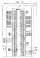
- FIG. 6 is a schematic of another embodiment of the present invention, where sixteen partially defective 1024K ⁇ 8 ⁇ 2 SDRAM components 72 to 87 are used to create a 1024K ⁇ 64 ⁇ 2 memory module.
- Each of the partially defective SDRAM components in FIG. 6 has four unreliable or unused outputs (DQ 0 to DQ 3 ) and four nondefective outputs (DQ 4 to DQ 7 ). Using the four nondefective outputs from each of the sixteen SDRAM components provides a 64 bit quad word data path.
- the SDRAM components of FIG. 6 are addressed by first presenting an eleven bit row address followed by a nine bit column address. Thus, the memory address is twenty bits wide. An additional bit is presented at address input A 11 with the eleven-bit row address to select one of the two 1024K memory banks within each SDRAM component.
- the present invention does not necessarily require any particular arrangement for the defective DQ outputs.
- the defective DQ outputs need not be the same for each component 72 - 87 , and the defective outputs may not be consecutive or symmetric.
- the components 72 and 80 make up the low order byte of data in the 64-bit quad word. It is possible that component 72 may have only three defective outputs, thereby allowing five bits in the low order byte to be taken from component 72 , and only three bits from component 80 . Any other combination would also be appropriate.
- the defective outputs in component 80 could come in any combination, and need not be DQ 0 , DQ 1 , DQ 2 , DQ 3 . Rather, the defective outputs could be DQ 1 , DQ 4 , DQ 6 , and DQ 7 , or any other combination.
- the SDRAM components in FIG. 7 are 1M ⁇ 8 ⁇ 2 components having two banks of 1M ⁇ 8 bit memory, it is possible that they could be 2M ⁇ 8 bit components having only a single bank of memory.
- the components are addressed by first presenting a twelve bit row address to the address inputs A 0 to A 11 , followed by a nine bit column address, which is presented at address inputs A 0 to A 8 .
- the full address is 21 bits wide, thereby providing a 2M address space, and the SDRAM components have (or are treated as having) only a single bank of memory.
- the memory components have more than two banks of memory.
- two bank select lines e.g., BA 0 and BA 1
- BA 0 and BA 1 are used to select one of four banks of memory in a particular component or module.
- select signals are presented to the component with the row address.
- the present invention is applicable to memory components of this nature, and is applicable generally to memory components having any number of banks of memory.
Abstract
Description
Claims (18)
Priority Applications (1)
| Application Number | Priority Date | Filing Date | Title |
|---|---|---|---|
| US09/938,461 US6621748B2 (en) | 1998-03-05 | 2001-08-21 | Recovery of useful areas of partially defective synchronous memory components |
Applications Claiming Priority (2)
| Application Number | Priority Date | Filing Date | Title |
|---|---|---|---|
| US09/035,629 US6314527B1 (en) | 1998-03-05 | 1998-03-05 | Recovery of useful areas of partially defective synchronous memory components |
| US09/938,461 US6621748B2 (en) | 1998-03-05 | 2001-08-21 | Recovery of useful areas of partially defective synchronous memory components |
Related Parent Applications (1)
| Application Number | Title | Priority Date | Filing Date |
|---|---|---|---|
| US09/035,629 Continuation US6314527B1 (en) | 1998-03-05 | 1998-03-05 | Recovery of useful areas of partially defective synchronous memory components |
Publications (2)
| Publication Number | Publication Date |
|---|---|
| US20020085432A1 US20020085432A1 (en) | 2002-07-04 |
| US6621748B2 true US6621748B2 (en) | 2003-09-16 |
Family
ID=21883854
Family Applications (2)
| Application Number | Title | Priority Date | Filing Date |
|---|---|---|---|
| US09/035,629 Expired - Lifetime US6314527B1 (en) | 1998-03-05 | 1998-03-05 | Recovery of useful areas of partially defective synchronous memory components |
| US09/938,461 Expired - Fee Related US6621748B2 (en) | 1998-03-05 | 2001-08-21 | Recovery of useful areas of partially defective synchronous memory components |
Family Applications Before (1)
| Application Number | Title | Priority Date | Filing Date |
|---|---|---|---|
| US09/035,629 Expired - Lifetime US6314527B1 (en) | 1998-03-05 | 1998-03-05 | Recovery of useful areas of partially defective synchronous memory components |
Country Status (1)
| Country | Link |
|---|---|
| US (2) | US6314527B1 (en) |
Cited By (1)
| Publication number | Priority date | Publication date | Assignee | Title |
|---|---|---|---|---|
| CN100559507C (en) * | 2004-01-29 | 2009-11-11 | 群联电子股份有限公司 | The minisize storage device of tool write-protection function |
Families Citing this family (3)
| Publication number | Priority date | Publication date | Assignee | Title |
|---|---|---|---|---|
| US6578157B1 (en) | 2000-03-06 | 2003-06-10 | Micron Technology, Inc. | Method and apparatus for recovery of useful areas of partially defective direct rambus rimm components |
| US6831873B1 (en) * | 2002-09-12 | 2004-12-14 | Alcatel | Independent in-line SDRAM control |
| JP2008077783A (en) * | 2006-09-22 | 2008-04-03 | Fujitsu Ltd | Memory data processor, memory, and memory data processing program |
Citations (93)
| Publication number | Priority date | Publication date | Assignee | Title |
|---|---|---|---|---|
| US3714637A (en) | 1970-09-30 | 1973-01-30 | Ibm | Monolithic memory utilizing defective storage cells |
| US3715735A (en) | 1970-12-14 | 1973-02-06 | Monolithic Memories Inc | Segmentized memory module and method of making same |
| US3735368A (en) | 1971-06-25 | 1973-05-22 | Ibm | Full capacity monolithic memory utilizing defective storage cells |
| US3772652A (en) | 1969-06-21 | 1973-11-13 | Licentia Gmbh | Data storage system with means for eliminating defective storage locations |
| US3781826A (en) | 1971-11-15 | 1973-12-25 | Ibm | Monolithic memory utilizing defective storage cells |
| US3800294A (en) | 1973-06-13 | 1974-03-26 | Ibm | System for improving the reliability of systems using dirty memories |
| US3845476A (en) | 1972-12-29 | 1974-10-29 | Ibm | Monolithic memory using partially defective chips |
| US4355376A (en) | 1980-09-30 | 1982-10-19 | Burroughs Corporation | Apparatus and method for utilizing partially defective memory devices |
| US4376300A (en) | 1981-01-02 | 1983-03-08 | Intel Corporation | Memory system employing mostly good memories |
| US4450560A (en) | 1981-10-09 | 1984-05-22 | Teradyne, Inc. | Tester for LSI devices and memory devices |
| US4475194A (en) | 1982-03-30 | 1984-10-02 | International Business Machines Corporation | Dynamic replacement of defective memory words |
| US4479214A (en) | 1982-06-16 | 1984-10-23 | International Business Machines Corporation | System for updating error map of fault tolerant memory |
| US4493075A (en) | 1982-05-17 | 1985-01-08 | National Semiconductor Corporation | Self repairing bulk memory |
| US4527251A (en) | 1982-12-17 | 1985-07-02 | Honeywell Information Systems Inc. | Remap method and apparatus for a memory system which uses partially good memory devices |
| US4646299A (en) | 1983-08-01 | 1987-02-24 | Fairchild Semiconductor Corporation | Method and apparatus for applying and monitoring programmed test signals during automated testing of electronic circuits |
| US4807191A (en) | 1988-01-04 | 1989-02-21 | Motorola, Inc. | Redundancy for a block-architecture memory |
| US4837747A (en) | 1986-11-29 | 1989-06-06 | Mitsubishi Denki Kabushiki Kaisha | Redundary circuit with a spare main decoder responsive to an address of a defective cell in a selected cell block |
| US4876685A (en) | 1987-06-08 | 1989-10-24 | Teradyne, Inc. | Failure information processing in automatic memory tester |
| US4881200A (en) | 1987-10-22 | 1989-11-14 | Nec Corporation | Erasable programmable read only memory device |
| US4908798A (en) | 1987-07-20 | 1990-03-13 | Nec Corporation | Semiconductor memory device with memory cell arrays and a redundant memory cell array associated with a small number of write-in and sense amplifying circuits |
| US4918662A (en) | 1987-03-27 | 1990-04-17 | Nec Corporation | Semiconductor memory device having redundant structure for segmented word line arrangement |
| US4935899A (en) | 1988-01-19 | 1990-06-19 | Nec Corporation | Semiconductor memory device with redundant memory cells |
| US4992984A (en) | 1989-12-28 | 1991-02-12 | International Business Machines Corporation | Memory module utilizing partially defective memory chips |
| US5051994A (en) | 1989-04-28 | 1991-09-24 | International Business Machines Corporation | Computer memory module |
| US5060197A (en) | 1989-12-30 | 1991-10-22 | Samsung Electronics Co., Ltd | Static random access memory with redundancy |
| US5124948A (en) | 1988-03-18 | 1992-06-23 | Makoto Takizawa | Mask ROM with spare memory cells |
| US5126973A (en) | 1990-02-14 | 1992-06-30 | Texas Instruments Incorporated | Redundancy scheme for eliminating defects in a memory device |
| US5134584A (en) | 1988-07-22 | 1992-07-28 | Vtc Incorporated | Reconfigurable memory |
| US5200959A (en) | 1989-10-17 | 1993-04-06 | Sundisk Corporation | Device and method for defect handling in semi-conductor memory |
| US5208775A (en) | 1990-09-07 | 1993-05-04 | Samsung Electronics Co., Ltd. | Dual-port memory device |
| US5233614A (en) | 1991-01-07 | 1993-08-03 | International Business Machines Corporation | Fault mapping apparatus for memory |
| US5243570A (en) | 1992-01-31 | 1993-09-07 | Nec Corporation | Semiconductor memory device having redundant memory cell columns concurrently accessible together with regular memory cell arrays |
| US5251174A (en) | 1992-06-12 | 1993-10-05 | Acer Incorporated | Memory system |
| US5268866A (en) | 1992-03-02 | 1993-12-07 | Motorola, Inc. | Memory with column redundancy and localized column redundancy control signals |
| US5270976A (en) | 1990-06-19 | 1993-12-14 | Texas Instruments Incorporated | Laser link decoder for DRAM redundancy scheme |
| US5270974A (en) | 1990-09-07 | 1993-12-14 | Alliance Semiconductor Corporation | Monolithic fail bit memory |
| US5315552A (en) | 1991-08-29 | 1994-05-24 | Kawasaki Steel Corporation | Memory module, method for control thereof and method for setting fault bit table for use therewith |
| US5327380A (en) | 1988-10-31 | 1994-07-05 | Texas Instruments Incorporated | Method and apparatus for inhibiting a predecoder when selecting a redundant row line |
| US5331188A (en) | 1992-02-25 | 1994-07-19 | International Business Machines Corporation | Non-volatile DRAM cell |
| US5332922A (en) | 1990-04-26 | 1994-07-26 | Hitachi, Ltd. | Multi-chip semiconductor package |
| US5337277A (en) | 1992-03-09 | 1994-08-09 | Samsung Electronics Co., Ltd. | Row redundancy circuit for a semiconductor memory device |
| US5349556A (en) | 1992-07-13 | 1994-09-20 | Samsung Electronics Co., Ltd. | Row redundancy circuit sharing a fuse box |
| US5371866A (en) | 1992-06-01 | 1994-12-06 | Staktek Corporation | Simulcast standard multichip memory addressing system |
| US5379415A (en) | 1992-09-29 | 1995-01-03 | Zitel Corporation | Fault tolerant memory system |
| US5390129A (en) | 1992-07-06 | 1995-02-14 | Motay Electronics, Inc. | Universal burn-in driver system and method therefor |
| US5392247A (en) | 1991-09-19 | 1995-02-21 | Mitsubishi Denki Kabushiki Kaisha | Semiconductor memory device including redundancy circuit |
| US5400342A (en) | 1986-10-20 | 1995-03-21 | Nippon Telegraph & Telephone Corporation | Semiconductor memory having test circuit and test method thereof |
| US5400263A (en) | 1992-04-06 | 1995-03-21 | Hewlett-Packard Company | Apparatus and method for specifying the flow of test execution and the binning for a testing system |
| US5406565A (en) | 1989-06-07 | 1995-04-11 | Mv Limited | Memory array of integrated circuits capable of replacing faulty cells with a spare |
| US5410545A (en) | 1992-07-28 | 1995-04-25 | Digital Equipment Corporation | Long-term storage of controller performance |
| US5424989A (en) | 1992-08-21 | 1995-06-13 | Kabushiki Kaisha Toshiba | Semiconductor memory device |
| US5434792A (en) | 1992-10-28 | 1995-07-18 | Fujitsu Limited | Versatile production system |
| US5465234A (en) | 1993-11-26 | 1995-11-07 | Nec Corporation | Semiconductor memory device having shifting circuit connected between data bus lines and data buffer circuits for changing connections therebetween |
| US5469390A (en) | 1993-09-16 | 1995-11-21 | Hitachi, Ltd. | Semiconductor memory system with the function of the replacement to the other chips |
| US5475695A (en) | 1993-03-19 | 1995-12-12 | Semiconductor Diagnosis & Test Corporation | Automatic failure analysis system |
| US5475648A (en) | 1992-02-07 | 1995-12-12 | Matsushita Electric Industrial Co., Ltd. | Redundancy semiconductor memory device which utilizes spare memory cells from a plurality of different memory blocks, and utilizes the same decode lines for both the primary and spare memory cells |
| US5491664A (en) | 1993-09-27 | 1996-02-13 | Cypress Semiconductor Corporation | Flexibilitiy for column redundancy in a divided array architecture |
| US5497381A (en) | 1993-10-15 | 1996-03-05 | Analog Devices, Inc. | Bitstream defect analysis method for integrated circuits |
| US5502333A (en) | 1994-03-30 | 1996-03-26 | International Business Machines Corporation | Semiconductor stack structures and fabrication/sparing methods utilizing programmable spare circuit |
| US5513327A (en) | 1990-04-18 | 1996-04-30 | Rambus, Inc. | Integrated circuit I/O using a high performance bus interface |
| US5513135A (en) | 1994-12-02 | 1996-04-30 | International Business Machines Corporation | Synchronous memory packaged in single/dual in-line memory module and method of fabrication |
| US5528553A (en) | 1993-10-01 | 1996-06-18 | Hal Computer Systems, Inc. | Method and apparatus for testing random access memory |
| US5535328A (en) | 1989-04-13 | 1996-07-09 | Sandisk Corporation | Non-volatile memory system card with flash erasable sectors of EEprom cells including a mechanism for substituting defective cells |
| US5538115A (en) | 1993-04-08 | 1996-07-23 | Stabilus Gmbh | Motor driven rotational to translational actuator for a piston cylinder |
| US5539697A (en) | 1994-08-03 | 1996-07-23 | Bi-Search Corporation | Method and structure for using defective unrepairable semiconductor memory |
| US5544106A (en) | 1994-02-15 | 1996-08-06 | Nec Corporation | Semiconductor memory device with redundant decoder available for test sequence on redundant memory cells |
| US5548553A (en) | 1994-12-12 | 1996-08-20 | Digital Equipment Corporation | Method and apparatus for providing high-speed column redundancy |
| US5576999A (en) | 1994-06-30 | 1996-11-19 | Samsung Electronics Co., Ltd. | Redundancy circuit of a semiconductor memory device |
| US5588115A (en) | 1993-01-29 | 1996-12-24 | Teradyne, Inc. | Redundancy analyzer for automatic memory tester |
| US5600258A (en) | 1993-09-15 | 1997-02-04 | Intest Corporation | Method and apparatus for automated docking of a test head to a device handler |
| US5602987A (en) | 1989-04-13 | 1997-02-11 | Sandisk Corporation | Flash EEprom system |
| US5631868A (en) | 1995-11-28 | 1997-05-20 | International Business Machines Corporation | Method and apparatus for testing redundant word and bit lines in a memory array |
| US5633826A (en) | 1994-11-22 | 1997-05-27 | Nec Corporation | Semiconductor memory wherein a signal selectively substitutes a redundant memory cell link for a faulty ordinary memory cell link |
| US5636173A (en) | 1995-06-07 | 1997-06-03 | Micron Technology, Inc. | Auto-precharge during bank selection |
| US5654204A (en) | 1994-07-20 | 1997-08-05 | Anderson; James C. | Die sorter |
| US5668763A (en) | 1996-02-26 | 1997-09-16 | Fujitsu Limited | Semiconductor memory for increasing the number of half good memories by selecting and using good memory blocks |
| US5717694A (en) | 1995-08-22 | 1998-02-10 | Advantest Corp. | Fail analysis device for semiconductor memory test system |
| US5734621A (en) | 1995-12-01 | 1998-03-31 | Sharp Kabushiki Kaisha | Semiconductor memory device |
| US5745673A (en) | 1994-09-21 | 1998-04-28 | Texas Instruments Incorporated | Memory architecture for solid state discs |
| US5754753A (en) | 1992-06-11 | 1998-05-19 | Digital Equipment Corporation | Multiple-bit error correction in computer main memory |
| US5758056A (en) | 1996-02-08 | 1998-05-26 | Barr; Robert C. | Memory system having defective address identification and replacement |
| US5768173A (en) | 1995-11-11 | 1998-06-16 | Samsung Electronics Co., Ltd. | Memory modules, circuit substrates and methods of fabrication therefor using partially defective memory devices |
| US5798962A (en) | 1996-07-26 | 1998-08-25 | Texas Instruments Incorporated | Memory schemes |
| US5841710A (en) | 1997-02-14 | 1998-11-24 | Micron Electronics, Inc. | Dynamic address remapping decoder |
| US5862314A (en) | 1996-11-01 | 1999-01-19 | Micron Electronics, Inc. | System and method for remapping defective memory locations |
| US5896346A (en) | 1997-08-21 | 1999-04-20 | International Business Machines Corporation | High speed and low cost SDRAM memory subsystem |
| US5913020A (en) | 1996-09-20 | 1999-06-15 | Micron Electronics, Inc. | Method for using fuse identification codes for masking bad bits on single in-line memory modules |
| US5920513A (en) | 1997-08-22 | 1999-07-06 | Micron Technology, Inc. | Partial replacement of partially defective memory devices |
| US5926838A (en) * | 1997-03-19 | 1999-07-20 | Micron Electronics | Interface for high speed memory |
| US5987623A (en) * | 1996-04-11 | 1999-11-16 | Oki Electric Industry Co., Ltd. | Terminal mapping apparatus |
| US6119049A (en) * | 1996-08-12 | 2000-09-12 | Tandon Associates, Inc. | Memory module assembly using partially defective chips |
| US6134638A (en) * | 1997-08-13 | 2000-10-17 | Compaq Computer Corporation | Memory controller supporting DRAM circuits with different operating speeds |
| US6397312B1 (en) * | 1997-07-04 | 2002-05-28 | Fujitsu Limited | Memory subsystem operated in synchronism with a clock |
Family Cites Families (8)
| Publication number | Priority date | Publication date | Assignee | Title |
|---|---|---|---|---|
| JP3273440B2 (en) | 1994-10-19 | 2002-04-08 | マイクロン・テクノロジー・インコーポレーテッド | Efficient method for obtaining usable part from partially good memory integrated circuit |
| US5966724A (en) * | 1996-01-11 | 1999-10-12 | Micron Technology, Inc. | Synchronous memory device with dual page and burst mode operations |
| US5661677A (en) | 1996-05-15 | 1997-08-26 | Micron Electronics, Inc. | Circuit and method for on-board programming of PRD Serial EEPROMS |
| US5996096A (en) | 1996-11-15 | 1999-11-30 | International Business Machines Corporation | Dynamic redundancy for random access memory assemblies |
| US5974564A (en) | 1997-07-31 | 1999-10-26 | Micron Electronics, Inc. | Method for remapping defective memory bit sets to non-defective memory bit sets |
| US5956233A (en) * | 1997-12-19 | 1999-09-21 | Texas Instruments Incorporated | High density single inline memory module |
| US5995409A (en) | 1998-03-20 | 1999-11-30 | Silicon Aquarius, Inc. | Electrically-programmable read-only memory fabricated using a dynamic random access memory fabrication process and methods for programming same |
| US5991215A (en) | 1998-03-31 | 1999-11-23 | Micron Electronics, Inc. | Method for testing a memory chip in multiple passes |
-
1998
- 1998-03-05 US US09/035,629 patent/US6314527B1/en not_active Expired - Lifetime
-
2001
- 2001-08-21 US US09/938,461 patent/US6621748B2/en not_active Expired - Fee Related
Patent Citations (96)
| Publication number | Priority date | Publication date | Assignee | Title |
|---|---|---|---|---|
| US3772652A (en) | 1969-06-21 | 1973-11-13 | Licentia Gmbh | Data storage system with means for eliminating defective storage locations |
| US3714637A (en) | 1970-09-30 | 1973-01-30 | Ibm | Monolithic memory utilizing defective storage cells |
| US3715735A (en) | 1970-12-14 | 1973-02-06 | Monolithic Memories Inc | Segmentized memory module and method of making same |
| US3735368A (en) | 1971-06-25 | 1973-05-22 | Ibm | Full capacity monolithic memory utilizing defective storage cells |
| US3781826A (en) | 1971-11-15 | 1973-12-25 | Ibm | Monolithic memory utilizing defective storage cells |
| US3845476A (en) | 1972-12-29 | 1974-10-29 | Ibm | Monolithic memory using partially defective chips |
| US3800294A (en) | 1973-06-13 | 1974-03-26 | Ibm | System for improving the reliability of systems using dirty memories |
| US4355376A (en) | 1980-09-30 | 1982-10-19 | Burroughs Corporation | Apparatus and method for utilizing partially defective memory devices |
| US4376300A (en) | 1981-01-02 | 1983-03-08 | Intel Corporation | Memory system employing mostly good memories |
| US4450560A (en) | 1981-10-09 | 1984-05-22 | Teradyne, Inc. | Tester for LSI devices and memory devices |
| US4475194A (en) | 1982-03-30 | 1984-10-02 | International Business Machines Corporation | Dynamic replacement of defective memory words |
| US4493075A (en) | 1982-05-17 | 1985-01-08 | National Semiconductor Corporation | Self repairing bulk memory |
| US4479214A (en) | 1982-06-16 | 1984-10-23 | International Business Machines Corporation | System for updating error map of fault tolerant memory |
| US4527251A (en) | 1982-12-17 | 1985-07-02 | Honeywell Information Systems Inc. | Remap method and apparatus for a memory system which uses partially good memory devices |
| US4646299A (en) | 1983-08-01 | 1987-02-24 | Fairchild Semiconductor Corporation | Method and apparatus for applying and monitoring programmed test signals during automated testing of electronic circuits |
| US5400342A (en) | 1986-10-20 | 1995-03-21 | Nippon Telegraph & Telephone Corporation | Semiconductor memory having test circuit and test method thereof |
| US4837747A (en) | 1986-11-29 | 1989-06-06 | Mitsubishi Denki Kabushiki Kaisha | Redundary circuit with a spare main decoder responsive to an address of a defective cell in a selected cell block |
| US4918662A (en) | 1987-03-27 | 1990-04-17 | Nec Corporation | Semiconductor memory device having redundant structure for segmented word line arrangement |
| US4876685A (en) | 1987-06-08 | 1989-10-24 | Teradyne, Inc. | Failure information processing in automatic memory tester |
| US4908798A (en) | 1987-07-20 | 1990-03-13 | Nec Corporation | Semiconductor memory device with memory cell arrays and a redundant memory cell array associated with a small number of write-in and sense amplifying circuits |
| US4881200A (en) | 1987-10-22 | 1989-11-14 | Nec Corporation | Erasable programmable read only memory device |
| US4807191A (en) | 1988-01-04 | 1989-02-21 | Motorola, Inc. | Redundancy for a block-architecture memory |
| US4935899A (en) | 1988-01-19 | 1990-06-19 | Nec Corporation | Semiconductor memory device with redundant memory cells |
| US5124948A (en) | 1988-03-18 | 1992-06-23 | Makoto Takizawa | Mask ROM with spare memory cells |
| US5134584A (en) | 1988-07-22 | 1992-07-28 | Vtc Incorporated | Reconfigurable memory |
| US5327380A (en) | 1988-10-31 | 1994-07-05 | Texas Instruments Incorporated | Method and apparatus for inhibiting a predecoder when selecting a redundant row line |
| US5327380B1 (en) | 1988-10-31 | 1999-09-07 | Texas Instruments Inc | Method and apparatus for inhibiting a predecoder when selecting a redundant row line |
| US5535328A (en) | 1989-04-13 | 1996-07-09 | Sandisk Corporation | Non-volatile memory system card with flash erasable sectors of EEprom cells including a mechanism for substituting defective cells |
| US5602987A (en) | 1989-04-13 | 1997-02-11 | Sandisk Corporation | Flash EEprom system |
| US5051994A (en) | 1989-04-28 | 1991-09-24 | International Business Machines Corporation | Computer memory module |
| US5406565A (en) | 1989-06-07 | 1995-04-11 | Mv Limited | Memory array of integrated circuits capable of replacing faulty cells with a spare |
| US5200959A (en) | 1989-10-17 | 1993-04-06 | Sundisk Corporation | Device and method for defect handling in semi-conductor memory |
| US4992984A (en) | 1989-12-28 | 1991-02-12 | International Business Machines Corporation | Memory module utilizing partially defective memory chips |
| US5060197A (en) | 1989-12-30 | 1991-10-22 | Samsung Electronics Co., Ltd | Static random access memory with redundancy |
| US5126973A (en) | 1990-02-14 | 1992-06-30 | Texas Instruments Incorporated | Redundancy scheme for eliminating defects in a memory device |
| US5513327A (en) | 1990-04-18 | 1996-04-30 | Rambus, Inc. | Integrated circuit I/O using a high performance bus interface |
| US5332922A (en) | 1990-04-26 | 1994-07-26 | Hitachi, Ltd. | Multi-chip semiconductor package |
| US5270976A (en) | 1990-06-19 | 1993-12-14 | Texas Instruments Incorporated | Laser link decoder for DRAM redundancy scheme |
| US5208775A (en) | 1990-09-07 | 1993-05-04 | Samsung Electronics Co., Ltd. | Dual-port memory device |
| US5270974A (en) | 1990-09-07 | 1993-12-14 | Alliance Semiconductor Corporation | Monolithic fail bit memory |
| US5233614A (en) | 1991-01-07 | 1993-08-03 | International Business Machines Corporation | Fault mapping apparatus for memory |
| US5315552A (en) | 1991-08-29 | 1994-05-24 | Kawasaki Steel Corporation | Memory module, method for control thereof and method for setting fault bit table for use therewith |
| US5392247A (en) | 1991-09-19 | 1995-02-21 | Mitsubishi Denki Kabushiki Kaisha | Semiconductor memory device including redundancy circuit |
| US5243570A (en) | 1992-01-31 | 1993-09-07 | Nec Corporation | Semiconductor memory device having redundant memory cell columns concurrently accessible together with regular memory cell arrays |
| US5475648A (en) | 1992-02-07 | 1995-12-12 | Matsushita Electric Industrial Co., Ltd. | Redundancy semiconductor memory device which utilizes spare memory cells from a plurality of different memory blocks, and utilizes the same decode lines for both the primary and spare memory cells |
| US5331188A (en) | 1992-02-25 | 1994-07-19 | International Business Machines Corporation | Non-volatile DRAM cell |
| US5268866A (en) | 1992-03-02 | 1993-12-07 | Motorola, Inc. | Memory with column redundancy and localized column redundancy control signals |
| US5337277A (en) | 1992-03-09 | 1994-08-09 | Samsung Electronics Co., Ltd. | Row redundancy circuit for a semiconductor memory device |
| US5400263A (en) | 1992-04-06 | 1995-03-21 | Hewlett-Packard Company | Apparatus and method for specifying the flow of test execution and the binning for a testing system |
| US5371866A (en) | 1992-06-01 | 1994-12-06 | Staktek Corporation | Simulcast standard multichip memory addressing system |
| US5754753A (en) | 1992-06-11 | 1998-05-19 | Digital Equipment Corporation | Multiple-bit error correction in computer main memory |
| US5251174A (en) | 1992-06-12 | 1993-10-05 | Acer Incorporated | Memory system |
| US5390129A (en) | 1992-07-06 | 1995-02-14 | Motay Electronics, Inc. | Universal burn-in driver system and method therefor |
| US5349556A (en) | 1992-07-13 | 1994-09-20 | Samsung Electronics Co., Ltd. | Row redundancy circuit sharing a fuse box |
| US5410545A (en) | 1992-07-28 | 1995-04-25 | Digital Equipment Corporation | Long-term storage of controller performance |
| US5424989A (en) | 1992-08-21 | 1995-06-13 | Kabushiki Kaisha Toshiba | Semiconductor memory device |
| US5553231A (en) | 1992-09-29 | 1996-09-03 | Zitel Corporation | Fault tolerant memory system |
| US5379415A (en) | 1992-09-29 | 1995-01-03 | Zitel Corporation | Fault tolerant memory system |
| US5434792A (en) | 1992-10-28 | 1995-07-18 | Fujitsu Limited | Versatile production system |
| US5588115A (en) | 1993-01-29 | 1996-12-24 | Teradyne, Inc. | Redundancy analyzer for automatic memory tester |
| US5475695A (en) | 1993-03-19 | 1995-12-12 | Semiconductor Diagnosis & Test Corporation | Automatic failure analysis system |
| US5538115A (en) | 1993-04-08 | 1996-07-23 | Stabilus Gmbh | Motor driven rotational to translational actuator for a piston cylinder |
| US5600258A (en) | 1993-09-15 | 1997-02-04 | Intest Corporation | Method and apparatus for automated docking of a test head to a device handler |
| US5469390A (en) | 1993-09-16 | 1995-11-21 | Hitachi, Ltd. | Semiconductor memory system with the function of the replacement to the other chips |
| US5491664A (en) | 1993-09-27 | 1996-02-13 | Cypress Semiconductor Corporation | Flexibilitiy for column redundancy in a divided array architecture |
| US5528553A (en) | 1993-10-01 | 1996-06-18 | Hal Computer Systems, Inc. | Method and apparatus for testing random access memory |
| US5497381A (en) | 1993-10-15 | 1996-03-05 | Analog Devices, Inc. | Bitstream defect analysis method for integrated circuits |
| US5465234A (en) | 1993-11-26 | 1995-11-07 | Nec Corporation | Semiconductor memory device having shifting circuit connected between data bus lines and data buffer circuits for changing connections therebetween |
| US5544106A (en) | 1994-02-15 | 1996-08-06 | Nec Corporation | Semiconductor memory device with redundant decoder available for test sequence on redundant memory cells |
| US5502333A (en) | 1994-03-30 | 1996-03-26 | International Business Machines Corporation | Semiconductor stack structures and fabrication/sparing methods utilizing programmable spare circuit |
| US5576999A (en) | 1994-06-30 | 1996-11-19 | Samsung Electronics Co., Ltd. | Redundancy circuit of a semiconductor memory device |
| US5654204A (en) | 1994-07-20 | 1997-08-05 | Anderson; James C. | Die sorter |
| US5539697A (en) | 1994-08-03 | 1996-07-23 | Bi-Search Corporation | Method and structure for using defective unrepairable semiconductor memory |
| US5745673A (en) | 1994-09-21 | 1998-04-28 | Texas Instruments Incorporated | Memory architecture for solid state discs |
| US5633826A (en) | 1994-11-22 | 1997-05-27 | Nec Corporation | Semiconductor memory wherein a signal selectively substitutes a redundant memory cell link for a faulty ordinary memory cell link |
| US5513135A (en) | 1994-12-02 | 1996-04-30 | International Business Machines Corporation | Synchronous memory packaged in single/dual in-line memory module and method of fabrication |
| US5548553A (en) | 1994-12-12 | 1996-08-20 | Digital Equipment Corporation | Method and apparatus for providing high-speed column redundancy |
| US5636173A (en) | 1995-06-07 | 1997-06-03 | Micron Technology, Inc. | Auto-precharge during bank selection |
| US5717694A (en) | 1995-08-22 | 1998-02-10 | Advantest Corp. | Fail analysis device for semiconductor memory test system |
| US5768173A (en) | 1995-11-11 | 1998-06-16 | Samsung Electronics Co., Ltd. | Memory modules, circuit substrates and methods of fabrication therefor using partially defective memory devices |
| US5631868A (en) | 1995-11-28 | 1997-05-20 | International Business Machines Corporation | Method and apparatus for testing redundant word and bit lines in a memory array |
| US5734621A (en) | 1995-12-01 | 1998-03-31 | Sharp Kabushiki Kaisha | Semiconductor memory device |
| US5758056A (en) | 1996-02-08 | 1998-05-26 | Barr; Robert C. | Memory system having defective address identification and replacement |
| US5668763A (en) | 1996-02-26 | 1997-09-16 | Fujitsu Limited | Semiconductor memory for increasing the number of half good memories by selecting and using good memory blocks |
| US5987623A (en) * | 1996-04-11 | 1999-11-16 | Oki Electric Industry Co., Ltd. | Terminal mapping apparatus |
| US5798962A (en) | 1996-07-26 | 1998-08-25 | Texas Instruments Incorporated | Memory schemes |
| US6119049A (en) * | 1996-08-12 | 2000-09-12 | Tandon Associates, Inc. | Memory module assembly using partially defective chips |
| US5913020A (en) | 1996-09-20 | 1999-06-15 | Micron Electronics, Inc. | Method for using fuse identification codes for masking bad bits on single in-line memory modules |
| US5862314A (en) | 1996-11-01 | 1999-01-19 | Micron Electronics, Inc. | System and method for remapping defective memory locations |
| US5920512A (en) | 1997-02-14 | 1999-07-06 | Micron Electronics, Inc. | Dynamic address remapping decoder |
| US5841710A (en) | 1997-02-14 | 1998-11-24 | Micron Electronics, Inc. | Dynamic address remapping decoder |
| US5926838A (en) * | 1997-03-19 | 1999-07-20 | Micron Electronics | Interface for high speed memory |
| US6397312B1 (en) * | 1997-07-04 | 2002-05-28 | Fujitsu Limited | Memory subsystem operated in synchronism with a clock |
| US6134638A (en) * | 1997-08-13 | 2000-10-17 | Compaq Computer Corporation | Memory controller supporting DRAM circuits with different operating speeds |
| US5896346A (en) | 1997-08-21 | 1999-04-20 | International Business Machines Corporation | High speed and low cost SDRAM memory subsystem |
| US5920513A (en) | 1997-08-22 | 1999-07-06 | Micron Technology, Inc. | Partial replacement of partially defective memory devices |
Non-Patent Citations (6)
| Title |
|---|
| Micron Electronics, Inc.-Assignee, U.S. App. S/N 08/903,819, Filed Jul. 31, 1997, "System for Remapping Defective Memory Bit Sets." |
| Micron Electronics, Inc.—Assignee, U.S. App. S/N 08/903,819, Filed Jul. 31, 1997, "System for Remapping Defective Memory Bit Sets." |
| Micron Electronics, Inc.-Assignee, U.S. App. S/N 09/035,629, Filed Mar. 5, 1998, "Recovery of Partially Defective Synchronous Memory Components." |
| Micron Electronics, Inc.—Assignee, U.S. App. S/N 09/035,629, Filed Mar. 5, 1998, "Recovery of Partially Defective Synchronous Memory Components." |
| Micron Electronics, Inc.-Assignee, U.S. App. S/N 09/035,739, Filed Aug. 3, 2000, Method for Recovery of Useful Areas of Partially Defective Synchronous Memory Components. |
| Micron Electronics, Inc.—Assignee, U.S. App. S/N 09/035,739, Filed Aug. 3, 2000, Method for Recovery of Useful Areas of Partially Defective Synchronous Memory Components. |
Cited By (1)
| Publication number | Priority date | Publication date | Assignee | Title |
|---|---|---|---|---|
| CN100559507C (en) * | 2004-01-29 | 2009-11-11 | 群联电子股份有限公司 | The minisize storage device of tool write-protection function |
Also Published As
| Publication number | Publication date |
|---|---|
| US6314527B1 (en) | 2001-11-06 |
| US20020085432A1 (en) | 2002-07-04 |
Similar Documents
| Publication | Publication Date | Title |
|---|---|---|
| US5509132A (en) | Semiconductor memory device having an SRAM as a cache memory integrated on the same chip and operating method thereof | |
| US7573778B2 (en) | Semiconductor memory device | |
| US6480947B1 (en) | Multiport memory, data processor and data processing system | |
| KR100226596B1 (en) | Dynamic memory | |
| US5926827A (en) | High density SIMM or DIMM with RAS address re-mapping | |
| US5768173A (en) | Memory modules, circuit substrates and methods of fabrication therefor using partially defective memory devices | |
| US5251178A (en) | Low-power integrated circuit memory | |
| WO2000011676A1 (en) | An embedded dram architecture with local data drivers and programmable number of data read and data write lines | |
| US5925141A (en) | Semiconductor memory device with data scramble circuit | |
| US5361230A (en) | Memory device delaying timing of outputting data in a test mode as compared with a normal operating mode | |
| KR100437467B1 (en) | Multi-chip system having continuous burst read mode of operation | |
| US5640353A (en) | External compensation apparatus and method for fail bit dynamic random access memory | |
| US5745914A (en) | Technique for converting system signals from one address configuration to a different address configuration | |
| US5961657A (en) | Parallel test circuit for semiconductor memory device | |
| US5625596A (en) | Semiconductor memory device with improved operating speed | |
| GB2327272A (en) | Integrated circuit with means for outputting data from a number of internal data channels via a lower number of ouput contact pads | |
| US6621748B2 (en) | Recovery of useful areas of partially defective synchronous memory components | |
| US6332183B1 (en) | Method for recovery of useful areas of partially defective synchronous memory components | |
| US20010047464A1 (en) | Synchronous semiconductor memory device having a burst mode for improving efficiency of using the data bus | |
| US6718487B1 (en) | Method for high speed testing with low speed semiconductor test equipment | |
| JPH10134576A (en) | Semiconductor memory device | |
| US6381707B1 (en) | System for decoding addresses for a defective memory array | |
| JPS6350998A (en) | Semiconductor memory device | |
| JP2001352038A (en) | Semiconductor integrated circuit device | |
| US5986953A (en) | Input/output circuits and methods for testing integrated circuit memory devices |
Legal Events
| Date | Code | Title | Description |
|---|---|---|---|
| AS | Assignment |
Owner name: MICRON TECHNOLOGY, INC., IDAHO Free format text: ASSIGNMENT OF ASSIGNORS INTEREST;ASSIGNOR:MEI CALIFORNIA INC;REEL/FRAME:012232/0436 Effective date: 20010322 |
|
| FEPP | Fee payment procedure |
Free format text: PAYOR NUMBER ASSIGNED (ORIGINAL EVENT CODE: ASPN); ENTITY STATUS OF PATENT OWNER: LARGE ENTITY |
|
| FEPP | Fee payment procedure |
Free format text: PAYOR NUMBER ASSIGNED (ORIGINAL EVENT CODE: ASPN); ENTITY STATUS OF PATENT OWNER: LARGE ENTITY Free format text: PAYER NUMBER DE-ASSIGNED (ORIGINAL EVENT CODE: RMPN); ENTITY STATUS OF PATENT OWNER: LARGE ENTITY |
|
| FPAY | Fee payment |
Year of fee payment: 4 |
|
| AS | Assignment |
Owner name: ROUND ROCK RESEARCH, LLC,NEW YORK Free format text: ASSIGNMENT OF ASSIGNORS INTEREST;ASSIGNOR:MICRON TECHNOLOGY, INC.;REEL/FRAME:023786/0416 Effective date: 20091223 Owner name: ROUND ROCK RESEARCH, LLC, NEW YORK Free format text: ASSIGNMENT OF ASSIGNORS INTEREST;ASSIGNOR:MICRON TECHNOLOGY, INC.;REEL/FRAME:023786/0416 Effective date: 20091223 |
|
| FPAY | Fee payment |
Year of fee payment: 8 |
|
| REMI | Maintenance fee reminder mailed | ||
| LAPS | Lapse for failure to pay maintenance fees | ||
| STCH | Information on status: patent discontinuation |
Free format text: PATENT EXPIRED DUE TO NONPAYMENT OF MAINTENANCE FEES UNDER 37 CFR 1.362 |
|
| FP | Lapsed due to failure to pay maintenance fee |
Effective date: 20150916 |