US6631282B2 - Device for isolating regions of living tissue - Google Patents
Device for isolating regions of living tissue Download PDFInfo
- Publication number
- US6631282B2 US6631282B2 US09/970,021 US97002101A US6631282B2 US 6631282 B2 US6631282 B2 US 6631282B2 US 97002101 A US97002101 A US 97002101A US 6631282 B2 US6631282 B2 US 6631282B2
- Authority
- US
- United States
- Prior art keywords
- patient
- skin
- rigid member
- aperture
- measurement system
- Prior art date
- Legal status (The legal status is an assumption and is not a legal conclusion. Google has not performed a legal analysis and makes no representation as to the accuracy of the status listed.)
- Expired - Fee Related
Links
Images


Classifications
-
- A—HUMAN NECESSITIES
- A61—MEDICAL OR VETERINARY SCIENCE; HYGIENE
- A61B—DIAGNOSIS; SURGERY; IDENTIFICATION
- A61B5/00—Measuring for diagnostic purposes; Identification of persons
- A61B5/68—Arrangements of detecting, measuring or recording means, e.g. sensors, in relation to patient
- A61B5/6801—Arrangements of detecting, measuring or recording means, e.g. sensors, in relation to patient specially adapted to be attached to or worn on the body surface
- A61B5/684—Indicating the position of the sensor on the body
- A61B5/6841—Indicating the position of the sensor on the body by using templates
-
- A—HUMAN NECESSITIES
- A61—MEDICAL OR VETERINARY SCIENCE; HYGIENE
- A61B—DIAGNOSIS; SURGERY; IDENTIFICATION
- A61B5/00—Measuring for diagnostic purposes; Identification of persons
- A61B5/06—Devices, other than using radiation, for detecting or locating foreign bodies ; determining position of probes within or on the body of the patient
- A61B5/061—Determining position of a probe within the body employing means separate from the probe, e.g. sensing internal probe position employing impedance electrodes on the surface of the body
-
- A—HUMAN NECESSITIES
- A61—MEDICAL OR VETERINARY SCIENCE; HYGIENE
- A61B—DIAGNOSIS; SURGERY; IDENTIFICATION
- A61B5/00—Measuring for diagnostic purposes; Identification of persons
- A61B5/145—Measuring characteristics of blood in vivo, e.g. gas concentration, pH value; Measuring characteristics of body fluids or tissues, e.g. interstitial fluid, cerebral tissue
- A61B5/14532—Measuring characteristics of blood in vivo, e.g. gas concentration, pH value; Measuring characteristics of body fluids or tissues, e.g. interstitial fluid, cerebral tissue for measuring glucose, e.g. by tissue impedance measurement
-
- A—HUMAN NECESSITIES
- A61—MEDICAL OR VETERINARY SCIENCE; HYGIENE
- A61B—DIAGNOSIS; SURGERY; IDENTIFICATION
- A61B5/00—Measuring for diagnostic purposes; Identification of persons
- A61B5/145—Measuring characteristics of blood in vivo, e.g. gas concentration, pH value; Measuring characteristics of body fluids or tissues, e.g. interstitial fluid, cerebral tissue
- A61B5/1455—Measuring characteristics of blood in vivo, e.g. gas concentration, pH value; Measuring characteristics of body fluids or tissues, e.g. interstitial fluid, cerebral tissue using optical sensors, e.g. spectral photometrical oximeters
Definitions
- This invention relates generally to determining analyte concentrations within living tissue. More particularly, this invention relates to a device for isolating regions of living tissue for consistent transfer of thermal spectra to and from the tissue.
- U.S. Pat. No. 6,198,949 discloses a spectrometer for non-invasive transfer of thermal gradient spectra to and from living tissue.
- the spectrometer includes an infrared transmissive thermal mass, referred to as a thermal mass window, for inducing a transient temperature gradient in the tissue by means of conductive heat transfer with the tissue, and a cooling system in operative combination with the thermal mass for the cooling thereof.
- an infrared sensor for detecting infrared emissions from the tissue as the transient temperature gradient progresses into the tissue, and for providing output signals proportional to the detected infrared emissions.
- a data capture system is provided for sampling the output signals received from the infrared sensor as the transient temperature gradient progresses into to the tissue.
- the transient thermal gradients arising due to the intermittent heating and cooling of the patient's skin generate thermal spectra which yield very good measurements of the patient's blood glucose levels.
- a device and method are provided for use with a non-invasive optical measurement system, such as but not limited to a thermal gradient spectrometer for improved determination of analyte concentrations within living tissue.
- a site selector is secured to a patient's forearm thereby isolating a measurement site on the patient's skin for determination of blood glucose levels.
- the site selector attaches to or engages a window of the gradient spectrometer and thus forms an interface between the patient's skin and the window.
- the site selector When the spectrometer must be temporarily removed from contact with the patient's skin, such as to allow the patient mobility, the site selector is left secured to the forearm so as to maintain a consistent measurement site on the skin.
- the site selector will again form an interface between the spectrometer and the same location of skin as before.
- a device for use with a non-invasive optical measurement system comprises a generally flat member having an aperture passing from a first surface of the flat member to a second surface of the flat member.
- the flat member is preferably made of injection-molded plastic, and may be configured to minimize the formation of condensation thereon.
- the aperture has a predetermined cross-sectional shape and allows substantially unimpeded transmission of thermal spectra to and from skin of a patient through the flat member.
- the first surface comprises a contact surface which presses against the skin of the patient when the flat member is attached thereto.
- the second surface comprises an interface surface which is shaped to receive the non-invasive optical measurement system.
- a fastening strap may be connected to the flat member and adapted to attach the flat member to a predetermined location on the patient, such as a forearm.
- the fastening strap comprises a fixed end and an adjustable end.
- the fixed end passes through a first of opening within the flat member and the adjustable end passes through a second of opening within the flat member such that the fastening strap assumes an annular configuration having an interior surface and an exterior surface.
- the fixed end is folded back and affixed to the interior surface of the fastening strap, and the adjustable end is folded over and removably attached to the exterior surface of the fastening strap with a fastener such as a buckle or VelcroTM.
- the contact surface of the flat member includes adhesive material which is adapted to attach the flat member to the predetermined location on the patient.
- the contact surface includes a pressure sensitive adhesive surface which enables attaching the site selector to the patient's skin without using the above-mentioned fastening strap.
- the flat member and the aperture cooperate to grip the skin of the patient when pressed against the skin under force applied by the fastening strap. Furthermore, the flat member is coupled with the non-invasive optical measurement system such that removal of the measurement system from the flat member leaves the predetermined location on the patient substantially unaltered.
- the device comprises a generally flat member having an aperture passing from a first surface of the flat member to a second surface of the flat member.
- the flat member is made of a rigid material, such as injection-molded plastic.
- the aperture is adapted to allow substantially unimpeded transmission of thermal spectra to and from skin of a patient through the flat member.
- the first surface comprises a contact surface which presses against the skin of the patient when the flat member is attached thereto.
- the second surface comprises an interface surface which is shaped to receive the noninvasive optical measurement system.
- the interface surface preferably comprises at least one raised section which facilitates orienting the noninvasive optical measurement system relative to the flat member such that the noninvasive optical measurement system assumes angular and axial alignment with the aperture.
- the aperture preferably comprises at least one protrusion which facilitates attaching the noninvasive optical measurement system to the flat member such that the interface surface receives the noninvasive optical measurement system. The flat member and the aperture cooperate to grip the skin of the patient when applied to the skin.
- a fastening strap is connected to the flat member and is adapted to attach the flat member to the predetermined location on the skin of the patient.
- the fastening strap comprises a fixed end and an adjustable end.
- the fixed end passes through a first opening within the flat member and the adjustable end passes through a second opening within the flat member such that the fastening strap assumes an annular configuration having an interior surface and an exterior surface.
- the fixed end is folded back and affixed to the interior surface of the fastening strap, and the adjustable end is folded over and removably attached to the exterior surface of the fastening strap.
- Another aspect of the invention provides a method for consistently isolating regions of living tissue for transfer of thermal spectra between the tissue and a noninvasive optical measurement system.
- the method comprises attaching a site selector to a predetermined region of skin on a patient.
- the site selector comprises a generally flat member having an aperture passing from a first surface to a second surface of the flat member.
- the first surface comprises a contact surface which presses against the skin of the patient when the flat member is attached thereto, and the second surface comprises an interface surface which is adapted to receive the noninvasive optical measurement system.
- the aperture is adapted to allow substantially unimpeded transmission of thermal spectra through the flat member between the contact surface and the interface surface.
- Pressure between the site selector and the patient's skin causes the perimeter of the aperture to enter into a gripping relationship with the skin, thereby minimizing relative motion between the site selector and the skin.
- This gripping relationship provides location stability whereby the site selector is prevented from sliding across the skin when the site selector is pushed or otherwise acted on by an external force.
- the method further comprises placing the noninvasive optical measurement system in intimate contact with the interface surface of the site selector.
- a window of the noninvasive optical measurement system interfaces with the aperture and is placed in thermal contact with the predetermined region of skin on the patient.
- the noninvasive optical measurement system is removably attachable to the site selector such that the noninvasive optical measurement system may be attached to and detached from the site selector while the site selector remains attached to the skin of the patient such that a consistent measurement site on the skin is maintained.
- Another aspect of the invention provides a device for consistent placement of a predetermined region of a patient's skin against an analysis window of a noninvasive optical measurement system.
- the device comprises a contact surface of the noninvasive optical measurement system, which comprises the analysis window, a first alignment window, and a second alignment window, a first alignment mark printed on the patient, and a second alignment mark printed on the patient. Alignment of the first and second alignment windows respectively with the first and second alignment marks causes the predetermined region to align with the analysis window.
- the first and second alignment windows each provides optical access to skin of the patient, and thus enables visual navigation of the noninvasive optical measurement system on the skin.
- Still another aspect of the invention provides a method of consistently isolating regions of living tissue for transfer of thermal spectra between the tissue and a noninvasive optical measurement system.
- the method comprises applying a first alignment mark and a second alignment mark to a region of skin on a patient such that when the first alignment mark is coincident with a first alignment detector of the noninvasive optical measurement system and the second alignment mark is coincident with a second alignment detector of the noninvasive optical measurement system, an analysis window of the noninvasive optical measurement system is caused to be centered and aligned with a predetermined location on the skin.
- the method further comprises placing the window of the noninvasive optical measurement system in thermal contact with the predetermined location on the skin, and moving the skin and/or the noninvasive optical measurement system relatively until the first and second alignment detectors are centered and aligned respectively with the first and second alignment marks.
- a device for consistently isolating regions of living tissue for transfer of thermal spectra between the tissue and a noninvasive optical measurement system.
- the device comprises a site selector comprising a generally flat member having an aperture passing from a first surface of the flat member to a second surface of the flat member.
- the flat member is made of injection-molded plastic comprising a material which minimizes a formation of condensation thereon.
- the aperture is adapted to allow substantially unimpeded transfer of thermal spectra through the flat member.
- the first surface comprises a contact surface which presses against the skin of the patient when the flat member is attached thereto.
- the aperture grips the skin of the patient when the site selector is pressed thereon such that relative motion between the site selector and the skin is minimized.
- the second surface comprises an interface surface which is shaped to receive the noninvasive optical measurement system.
- the device further comprises an alignment marker printed onto the skin of the patient. Aligning the aperture with the alignment mark facilitates orienting the site selector relative to a predetermined location on the patient such that when the noninvasive optical measurement system is coupled with the site selector, the noninvasive optical measurement system is centered and aligned with the predetermined location on the patient.
- a method for consistently positioning a predetermined region of a patient's skin against a window of a noninvasive optical measurement system.
- the method comprises applying an alignment mark to the skin of the patient, aligning a site selection member with the alignment mark and securing the site selection member with respect to the skin of the patient, and coupling the noninvasive optical measurement system to the site selection member, thereby bringing the window of the noninvasive optical measurement system into thermal contact with the predetermined region on the patient.
- the site selection member preferably comprises a flat member having an aperture passing from a first surface of the flat member to a second surface of the flat member. The aperture allows substantially unimpeded transmission of thermal spectra to and from the skin of the patient through the flat member.
- the first surface comprises a contact surface which presses against the skin of the patient when the flat member is attached thereto, and the second surface comprises an interface surface which is shaped to receive the noninvasive optical measurement system.
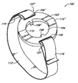
- FIG. 1 is a perspective view of one embodiment of a site selector.
- FIG. 2 is a side elevation view of the site selector of FIG. 1 .
- FIG. 3 is a top view of the site selector of FIG. 2, taken along line 3 — 3 .
- FIG. 4 is a perspective view of the site selector of FIG. 1 with an attached fastening strap.
- FIG. 5 shows the site selector of FIG. 1 strapped onto a forearm of a patient.
- FIG. 6 illustrates another embodiment of a site selector on a forearm of a patient.
- FIG. 7 illustrates one embodiment of an alignment marker which may be used in conjunction with the site selector of FIG. 1 on a forearm of a patient.
- FIG. 8 illustrates another embodiment of an alignment marker which may be used in conjunction with the site selector of FIG. 1 on a forearm of a patient.
- FIG. 1 is a perspective view of one embodiment of a site selector 100 .
- the site selector 100 is to be used in conjunction with a non-invasive optical measurement system such as, but not necessarily limited to, the apparatus taught in the above-mentioned U.S. Pat. No. 6,198,949.
- the non-invasive thermal gradient spectrometer comprises a window and a thermal mass window, wherein the window forms an interface between the thermal mass window and a patient's skin.
- the site selector 100 couples with, or otherwise operates in conjunction with the window and thus stabilizes the interface between the window and the patient's skin.
- the site selector 100 may be used in conjunction with the noninvasive thermal gradient spectrometer in accordance with the methodology taught in the above-mentioned U.S. Pat. No. 6,161,028.
- the site selector 100 is a generally flattened, rigid member comprising a contact surface 102 , an interface surface 103 , an aperture 104 , openings 106 , 106 ′, and protrusions 108 , 108 ′.
- the site selector 100 further comprises channels 107 , 107 ′, and raised sections 110 , 110 ′.
- the openings 106 , 106 ′ and the channels 107 , 107 ′ facilitate fastening the site selector 100 to a patient (see FIG. 5 ).
- the site selector 100 may be formed of injection-molded plastic or other similar material such that a non-invasive optical measurement system, such as the thermal gradient spectrometer taught in U.S.
- Pat. No. 6,198,949 may be coupled with the site selector 100 with minimal movement arising therebetween. Furthermore, it is contemplated that the material comprising the site selector 100 may be such that condensation formed thereon when the site selector 100 is exposed to cooler temperatures (below the dew point) is substantially minimized.
- the contact surface 102 presses against the patient's skin when the site selector 100 is strapped thereon or otherwise secured thereto.
- the contact surface 102 comprises a radius of curvature r which conforms to the topology of the location on the patient's body where the site selector 100 is intended to be used.
- the contact surface 102 is curved and has a radius of curvature r of about 3.0 inches.
- the contact surface 102 may advantageously be formed with other shapes or other radii of curvature r without departing from the scope of the invention.
- the interface surface 103 receives or otherwise engages with the above-mentioned non-invasive optical measurement system.
- the protrusions 108 , 108 ′ and the raised sections 110 , 110 ′ respectively facilitate attaching and/or aligning the optical measurement system to the site selector 100 .
- the configuration of the interface surface 103 (which, in the illustrated embodiment, includes the specific number, shapes, orientations, and characteristics of the protrusions 108 , 108 ′ and the raised sections 110 , 110 ′) is dependent upon the particular type of instrument with which the site selector 100 is intended to be used.
- the number, shapes, orientations and characteristics of the protrusions 108 , 108 ′ and the raised sections 110 , 110 ′ may be substantially altered without departing from the scope of the invention.
- the aperture 104 allows substantially unimpeded transmission of thermal spectra to and from the patient's skin through the site selector 100 .
- the aperture 104 preferably has a substantially circular cross-section having a diameter of about 2.0 inches. It will be appreciated, however, that while in the embodiment of FIGS. 1 and 3 the aperture 104 has a circular cross-sectional shape, other cross-sectional shapes and sizes are contemplated, such as, by way of example, rectangular, circular, diamond, elliptical, and ovoid. It will further be appreciated that different cross-sectional shapes and sizes may advantageously be combined, thereby forming additional cross-sectional shapes without departing from the scope of the invention.
- the aperture 104 may comprise a substrate which serves as a thermal window.
- the substrate preferably is made of a material having a high thermal conductivity, such as polycrystalline float zone silicon or other similar material, such that the substrate is transparent to thermal spectra.
- the substrate may have a thickness sized such that thermal spectra are substantially unimpeded in passing through the substrate. It is contemplated that a suitable substrate which may be used with the site selector 100 of FIGS. 1 through 3 has a thickness of about 0.25 millimeters. It is further contemplated that the substrate has a cross-sectional shape and size such that the substrate is receivable by the aperture 104 , thereby facilitating fastening of the substrate to the site selector 100 .
- the substrate may be permanently affixed within the aperture 104 .
- the substrate 104 may be removably inserted into the aperture 104 .
- the substrate may further comprise a disposable member which is attachable to and detachable from the site selector 100 . It will be appreciated by those of ordinary skill in the art, however, that the substrate may be comprised of other materials, cross-sectional shapes and thicknesses without detracting from the scope of the invention.
- a heating element may be disposed upon the above-mentioned substrate such that the heating element can heat the substrate and the skin when the site selector 100 is strapped to the patient.
- the heating element transfers heat to the skin of the patient, and thus gives rise to the heating component of the aforementioned intermittent heating and cooling of the patient's skin.
- One embodiment of the heating element comprises an adhesion layer of gold or platinum (hereinafter referred to as the “gold” layer) deposited over an alloy layer which is applied to the substrate.
- the alloy layer comprises a material suitable for implementation of the heating element, such as, by way of example, 10/90 titanium/tungsten, titanium/platinum, nickel/chromium, or other similar alloy.
- the gold layer preferably has a thickness of 4000 ⁇ , and the alloy layer preferably has a thickness ranging between 300 ⁇ and 500 ⁇ .
- the gold layer and/or the alloy layer may be deposited onto the substrate 104 by chemical deposition including, but not necessarily limited to, vapor deposition, liquid deposition, plating, laminating, casting, sintering, or other forming or deposition methodologies well known to those of ordinary skill in the art.
- the heating element may be created by etching or removing material from the gold and alloy layers such that a grid structure is formed, as is discussed in the above-mentioned U.S. Pat. No. 6,198,949.
- the heating element may comprise a grid structure which is formed as the material is being deposited onto the surface of the substrate by use of a mask or other known techniques. It is contemplated that such a heating element comprises materials, dimensions, and thermal properties which are substantially the same as those mentioned above.
- the site selector 100 may be made of a flexible, semi-compliant material which allows the site selector 100 to be bent such that it conforms to various regions of a patient's body.
- the site selector 100 may be made of polyurethane.
- the site selector 100 may be made of polypropylene.
- the site selector 100 may be made of silicone.
- Other embodiments may include other non-compliant or semi-compliant materials, or blends thereof, including but not limited to EVA (Ethylene-Vinyl-Acetate), PVC, PET, and NYLON.
- EVA Ethylene-Vinyl-Acetate
- PVC Polyvinylene-Vinyl-Acetate
- PET PET
- NYLON NYLON
- FIG. 4 is a perspective view illustrating the site selector 100 with one embodiment of a fastening strap 112 that may be used in conjunction with the site selector 100 .
- the fastening strap 112 comprises a fixed end 114 and an adjustable end 116 , which pass through the openings 106 ′, 106 , respectively.
- the channels 107 , 107 ′ allow the fixed and adjustable ends 114 , 116 to pass into the openings 106 , 106 ′ without rising above the plane of the interface surface 102 .
- the fixed end 114 is folded back and affixed to an interior surface of the strap 112 .
- the adjustable end 116 is folded over and affixed to an exterior surface of the strap 112 .
- the adjustable end 116 is removably attachable to the strap 112 , thereby facilitating fastening of the site selector 100 onto the patient (see FIG. 5 ), as well as subsequent removal therefrom.
- the fixed and adjustable ends 114 , 116 preferably include strips of VelcroTM (not shown) or other similar material which facilitates repeated attaching, adjusting and removing of the fastening strap 112 from the site selector 100 .
- the contact surface 102 may include an adhesive material which is adapted to attach the site selector 100 to the predetermined location on the patient.
- the contact surface 102 comprises a pressure sensitive adhesive surface which enables attaching the site selector 100 to the patient's skin without using the fastening strap 112 .
- FIG. 5 generally illustrates the use of the site selector 100 on the forearm 150 of the patient.
- the site selector 100 is strapped to the forearm 150 such that the contact surface 102 is pressed against the patient's skin, while the interface surface 103 , as well as the raised sections 110 , 110 ′, face outward away from the skin.
- Pressure between the site selector 100 and the patient's skin causes the perimeter of the aperture 104 to “grip” the skin, thereby substantially minimizing relative motion between the skin and the site selector 100 .
- This gripping of the skin provides location stability whereby the site selector 100 is prevented from sliding across the patient's skin when pushed or otherwise acted on by external forces, such as forces arising when the non-invasive optical measurement system is attached and detached from the site selector 100 .
- the site selector 100 covers up a region of the skin surrounding the portion of skin from which thermal spectral readings are taken, and prevents moisture evaporation from the covered region of skin. This is believed to preserve and stabilize the hydration level within the skin area from which readings are taken, as well as to reduce variance and error observed in repeated measurements over time.
- a non-invasive optical measurement system such as the apparatus taught in U.S. Pat. No. 6,198,949, is placed in intimate contact with the interface surface 103 such that a window of the measurement system interfaces with the aperture 104 and is placed in thermal contact with the patient's skin.
- the site selector 100 may be left strapped to the forearm 150 so as to maintain a consistent measurement site on the skin.
- the site selector 100 will again place the window of the measurement system in thermal contact with the same location of skin as before. This substantially reduces measurement errors arising due to the otherwise variable nature of the contact between the measurement system and the patient's skin.
- the site selector 100 is not restricted to use solely with the forearm 150 .
- the site selector 100 may advantageously be attached to the end of an index finger.
- one site selector 100 may be attached to the index finger while a second somewhat larger site selector 100 is at the same time attached to the forearm 150 , thereby allowing for comparison of measured values.
- the site selector 100 may advantageously be placed in intimate contact with any location of skin whereupon satisfactory measurements can be obtained.
- FIG. 6 illustrates another embodiment of a site selector 160 which may be used on the forearm 150 of the patient.
- the site selector 160 comprises a first window alignment mark 164 and a second window alignment mark 166 , both of which are printed, drawn or tattooed on the forearm 150 .
- the site selector 160 facilitates the positioning of a window 162 of an optical measurement system 170 on a predetermined location of skin.
- the window 162 serves to form an interface between a thermal mass window (not shown) within the optical measurement system 170 and the patient's skin.
- the first alignment mark 164 corresponds with a first alignment window 164 ′, which comprises a portion of a contact surface 168 of the optical measurement system 170 .
- the second alignment mark 166 corresponds with a second alignment window 166 ′, which also comprises a portion of the contact surface 168 .
- the window alignment marks 164 , 166 and the alignment windows 164 ′, 166 ′ facilitate orienting the optical measurement system 170 relative to the forearm 150 such that the window 162 is centered and aligned with the predetermined location of the skin. It is contemplated that the alignment windows 164 ′, 166 ′ each provides direct visual or optical access to the skin, thereby enabling a practitioner to visually navigate the optical measurement system 170 on the skin.
- the alignment marks 164 , 166 are applied to the forearm 150 of the patient.
- a non-invasive optical measurement system 170 such as the apparatus taught in U.S. Pat. No. 6,198,949, is then coupled to the site selector 100 placing the window 162 in thermal contact with the patient's skin. While in contact with the measurement system 170 , the patient's skin is moved on the system 170 (or vice versa) until the alignment marks 164 , 166 become aligned with the alignment windows 164 ′, 166 ′, respectively. If, for some reason, the measurement system 170 must be temporarily removed from the patient's skin, such as to allow the patient mobility, the site selector 160 remains on the forearm 150 designating a consistent measurement site on the skin. When the measurement system 170 is later attached to the patient, the site selector 160 will again enable placement of the window 162 of the measurement system 170 in contact with the same location of skin as before.
- FIG. 7 shows one embodiment of an alignment marker 180 which may be used in conjunction with the site selector 100 on the forearm 150 of the patient.
- the alignment marker 180 preferably comprises a first alignment mark 182 and a second alignment mark (or, where sufficient, a single alignment mark) 184 , both of which are printed, drawn or tattooed on the forearm 150 .
- the alignment marker 180 facilitates the positioning of site selector 100 on a predetermined location of skin.
- the first alignment mark 182 corresponds with a side 182 ′ of the site selector 100 and the second alignment mark 184 corresponds with an opposing side 184 ′ of the site selector 100 .
- the marks 182 , 184 may be placed on the skin such that the marks 182 , 184 correspond and align with opposite sides of the outer perimeter of the site selector 100 .
- the alignment marks 182 , 184 facilitate orienting the site selector 100 relative to the forearm 150 such that the aperture 104 is centered and aligned with the predetermined location of the skin. It is contemplated that the alignment marks 182 , 184 are separated by a distance whereby the marks 182 , 184 are out of the field of view of the window 162 (see FIG. 6) when the site selector 100 is properly oriented relative to the marks 182 , 184 .
- the alignment marks 182 , 184 are applied to the forearm 150 of the patient.
- the site selector 100 is then fastened to the forearm 150 and the patient's skin is moved on the site selector 100 (or vice versa) until the alignment marks 182 , 184 become respectively aligned with the sides 182 ′, 184 ′ of the aperture 104 .
- the non-invasive optical measurement system 170 (see FIG. 6) is coupled to the interface surface 103 such that the window 162 is placed in thermal contact with the patient's skin.
- the alignment marks 182 , 184 remain on the forearm 150 designating a consistent measurement site on the skin.
- the alignment marks 182 , 184 will again enable placement of the site selector 100 and the measurement system 170 in contact with the same location of skin as before. This substantially reduces measurement errors arising due to the otherwise variable nature of the contact between the measurement system 170 and the patient's skin.
- FIG. 8 illustrates another embodiment of an alignment marker 190 which may be used in conjunction with the site selector 100 .
- the alignment marker 190 comprises a first alignment mark 192 and a second alignment mark 194 which are both printed, drawn or tattooed on the forearm 150 .
- the alignment marker 190 facilitates the positioning of site selector 100 on a predetermined location of skin.
- the first alignment mark 192 corresponds with the protrusion 108 of the site selector 100 and the second alignment mark 194 corresponds with the opposing protrusion 108 ′ of the site selector 100 .
- the alignment marks 192 , 194 facilitate orienting the site selector 100 relative to the forearm 150 such that the aperture 104 is centered and aligned with the predetermined location of the skin. It is contemplated that the alignment marks 192 , 194 are separated by a distance whereby the marks 192 , 194 are out of the field of view of the window 162 (see FIG. 6) when the site selector 100 is properly oriented relative thereto.
- the function of the alignment marker 190 illustrated in FIG. 8 is substantially similar to the function of the alignment marker 180 illustrated in FIG. 7 .
- the alignment marks 192 , 194 are applied to the forearm 150 of the patient and the site selector 100 is fastened to the forearm 150 .
- the patient's skin is then moved on the site selector 100 (or vice versa) until the alignment marks 192 , 194 become respectively aligned with the protrusions 108 , 108 ′ within the aperture 104 .
- the optical measurement system 170 is coupled to the interface surface 103 such that the window 162 is placed in thermal contact with the patient's skin.
- the alignment marks 192 , 194 remain on the forearm 150 designating a consistent measurement site on the skin.
- the alignment marks 192 , 194 will facilitate the positioning of the site selector 100 , and consequently the measurement system 170 , over the same location of skin as before.
- the alignment markers 180 , 190 are not restricted to use solely with the forearm 150 .
- the alignment markers 180 , 190 may advantageously be printed, drawn or tattooed on the end of an index finger.
- one of the alignment markers 180 , 190 may be applied to the index finger while a second somewhat larger embodiment of the alignment markers 180 , 190 is applied to the forearm 150 , thereby enabling a use of two site selectors 100 at the same time for a comparison of measured values.
- the alignment markers 180 , 190 may advantageously be applied to any location of skin whereupon use of the site selector 100 yields satisfactory measurements.
- the alignment markers 180 , 190 may advantageously be combined to form other types of alignment markers having different shapes, sizes, and orientations.
Abstract
Description
Claims (22)
Priority Applications (2)
| Application Number | Priority Date | Filing Date | Title |
|---|---|---|---|
| US09/970,021 US6631282B2 (en) | 2001-08-09 | 2001-10-02 | Device for isolating regions of living tissue |
| PCT/US2002/025368 WO2003013352A1 (en) | 2001-08-09 | 2002-08-08 | Device for isolating regions of living tissue |
Applications Claiming Priority (2)
| Application Number | Priority Date | Filing Date | Title |
|---|---|---|---|
| US31152101P | 2001-08-09 | 2001-08-09 | |
| US09/970,021 US6631282B2 (en) | 2001-08-09 | 2001-10-02 | Device for isolating regions of living tissue |
Publications (2)
| Publication Number | Publication Date |
|---|---|
| US20030032872A1 US20030032872A1 (en) | 2003-02-13 |
| US6631282B2 true US6631282B2 (en) | 2003-10-07 |
Family
ID=26977928
Family Applications (1)
| Application Number | Title | Priority Date | Filing Date |
|---|---|---|---|
| US09/970,021 Expired - Fee Related US6631282B2 (en) | 2001-08-09 | 2001-10-02 | Device for isolating regions of living tissue |
Country Status (2)
| Country | Link |
|---|---|
| US (1) | US6631282B2 (en) |
| WO (1) | WO2003013352A1 (en) |
Cited By (29)
| Publication number | Priority date | Publication date | Assignee | Title |
|---|---|---|---|---|
| US20030220581A1 (en) * | 2002-03-26 | 2003-11-27 | Stig Ollmar | Non-invasive in vivo determination of body fluid parameter |
| US20050014997A1 (en) * | 1997-08-14 | 2005-01-20 | Ruchti Timothy L. | Method of sample control and calibration adjustment for use with a noninvasive analyzer |
| US20050027176A1 (en) * | 2003-07-31 | 2005-02-03 | Skymoon Research & Development, Llc | Optical in vivo analyte probe using embedded intradermal particles |
| US20050054908A1 (en) * | 2003-03-07 | 2005-03-10 | Blank Thomas B. | Photostimulation method and apparatus in combination with glucose determination |
| US20050197555A1 (en) * | 2004-03-06 | 2005-09-08 | Calisto Medical, Inc. | Methods and devices for non-invasively measuring quantitative information of substances in living organisms |
| US6959211B2 (en) | 1999-03-10 | 2005-10-25 | Optiscan Biomedical Corp. | Device for capturing thermal spectra from tissue |
| US20050267342A1 (en) * | 2004-04-28 | 2005-12-01 | Blank Thomas B | Noninvasive analyzer sample probe interface method and apparatus |
| US20060015023A1 (en) * | 2004-06-10 | 2006-01-19 | Monfre Stephen L | Preparation kit for noninvasive glucose concentration determination |
| US20060116562A1 (en) * | 2002-03-08 | 2006-06-01 | Acosta George M | Compact apparatus for noninvasive measurement of glucose through near-infrared spectroscopy |
| WO2006091911A2 (en) * | 2000-05-02 | 2006-08-31 | Sensys Medical, Inc. | Noninvasive analyzer sample probe interface method and apparatus |
| US20060200017A1 (en) * | 2002-03-08 | 2006-09-07 | Monfre Stephen L | Noninvasive targeting system method and apparatus |
| US20060206018A1 (en) * | 2005-03-04 | 2006-09-14 | Alan Abul-Haj | Method and apparatus for noninvasive targeting |
| US20070038046A1 (en) * | 2005-08-09 | 2007-02-15 | Hayter Paul G | Kinematic fluorescence measurement band |
| US20070038045A1 (en) * | 2005-08-09 | 2007-02-15 | Hayter Paul G | Method for monitoring an implanted fluorescent light-emitting bead |
| US20070149868A1 (en) * | 2002-03-08 | 2007-06-28 | Blank Thomas B | Method and Apparatus for Photostimulation Enhanced Analyte Property Estimation |
| US20070234300A1 (en) * | 2003-09-18 | 2007-10-04 | Leake David W | Method and Apparatus for Performing State-Table Driven Regression Testing |
| US20080033275A1 (en) * | 2004-04-28 | 2008-02-07 | Blank Thomas B | Method and Apparatus for Sample Probe Movement Control |
| US20080319382A1 (en) * | 2002-03-08 | 2008-12-25 | Blank Thomas B | Method and apparatus for coupling a channeled sample probe to tissue |
| US20080319299A1 (en) * | 2004-04-28 | 2008-12-25 | Stippick Timothy W | Method and apparatus for controlling positioning of a noninvasive analyzer sample probe |
| US20090171384A1 (en) * | 2008-01-02 | 2009-07-02 | Hack Jason B | Emergency snake bite treatment devices, medical kits and related methods |
| US20110166456A1 (en) * | 2010-01-05 | 2011-07-07 | Seiko Epson Corporation | Biological information detector and biological information measuring device |
| US8718738B2 (en) | 2002-03-08 | 2014-05-06 | Glt Acquisition Corp. | Method and apparatus for coupling a sample probe with a sample site |
| WO2016063082A1 (en) * | 2014-10-24 | 2016-04-28 | Cambridge temperature concepts ltd | A wearable sensing assembly |
| US9364182B2 (en) * | 2013-03-18 | 2016-06-14 | Maisense Inc. | Pulse measurement devices for bio-signals |
| US20160192885A1 (en) * | 2015-01-07 | 2016-07-07 | Samsung Electronics Co., Ltd. | Apparatus and method for measuring biological signal |
| US11326944B2 (en) * | 2019-07-12 | 2022-05-10 | Biospex, Inc. | Wearable spectrometer with filtered sensor |
| US11402269B2 (en) | 2019-02-28 | 2022-08-02 | Biospex, Inc. | Advanced fluorescence and systemic noise reduction in time-gated spectroscopy |
| US11454540B2 (en) | 2019-07-12 | 2022-09-27 | Biospex, Inc. | Wearable spectroscopy using filtered sensor |
| US20230026387A1 (en) * | 2021-07-20 | 2023-01-26 | Freedom Band LLC | Systems and apparatuses for protecting continuous glucose monitoring and insulin infusion devices |
Families Citing this family (3)
| Publication number | Priority date | Publication date | Assignee | Title |
|---|---|---|---|---|
| US20050090725A1 (en) * | 2003-10-28 | 2005-04-28 | Joseph Page | Disposable couplings for biometric instruments |
| CN1950026B (en) * | 2004-05-11 | 2012-06-20 | 皇家飞利浦电子股份有限公司 | Measurement head for non-invasive blood analysis |
| WO2009083942A1 (en) * | 2007-12-30 | 2009-07-09 | Deepbreeze Ltd. | Diagnostic system for accurate recording of acoustic signals |
Citations (30)
| Publication number | Priority date | Publication date | Assignee | Title |
|---|---|---|---|---|
| US4798955A (en) * | 1987-09-23 | 1989-01-17 | Futrex, Inc. | Measurement locator and light shield for use in interactance testing of body composition and method for use thereof |
| US4953552A (en) | 1989-04-21 | 1990-09-04 | Demarzo Arthur P | Blood glucose monitoring system |
| US5028787A (en) * | 1989-01-19 | 1991-07-02 | Futrex, Inc. | Non-invasive measurement of blood glucose |
| US5035243A (en) | 1988-03-26 | 1991-07-30 | Nicolay Gmbh | Holder sleeve for positioning a detecting and measuring sensor |
| US5140985A (en) | 1989-12-11 | 1992-08-25 | Schroeder Jon M | Noninvasive blood glucose measuring device |
| US5211160A (en) | 1988-09-14 | 1993-05-18 | Interpore Orthopaedics, Inc. | Ultrasonic orthopedic treatment head and body-mounting means therefor |
| US5313941A (en) | 1993-01-28 | 1994-05-24 | Braig James R | Noninvasive pulsed infrared spectrophotometer |
| US5419321A (en) | 1990-05-17 | 1995-05-30 | Johnson & Johnson Professional Products Limited | Non-invasive medical sensor |
| US5515847A (en) | 1993-01-28 | 1996-05-14 | Optiscan, Inc. | Self-emission noninvasive infrared spectrophotometer |
| US5615672A (en) | 1993-01-28 | 1997-04-01 | Optiscan, Inc. | Self-emission noninvasive infrared spectrophotometer with body temperature compensation |
| US5642733A (en) | 1996-04-08 | 1997-07-01 | Medwave, Inc. | Blood pressure sensor locator |
| US5769076A (en) | 1995-05-02 | 1998-06-23 | Toa Medical Electronics Co., Ltd. | Non-invasive blood analyzer and method using the same |
| US5772587A (en) | 1993-12-16 | 1998-06-30 | The Board Of Trustees Of The University Of Illinois | Photosensor with multiple light sources |
| US5771890A (en) | 1994-06-24 | 1998-06-30 | Cygnus, Inc. | Device and method for sampling of substances using alternating polarity |
| US5823951A (en) | 1995-08-09 | 1998-10-20 | Rio Grande Medical Technologies, Inc. | Method for non-invasive blood analyte measurement with improved optical interface |
| US5827183A (en) | 1995-09-12 | 1998-10-27 | Cygnus, Inc. | Method of measuring chemical concentration iontophoretically using impermeable mask |
| US5877500A (en) | 1997-03-13 | 1999-03-02 | Optiscan Biomedical Corporation | Multichannel infrared detector with optical concentrators for each channel |
| US5879373A (en) * | 1994-12-24 | 1999-03-09 | Boehringer Mannheim Gmbh | System and method for the determination of tissue properties |
| US5900632A (en) | 1997-03-12 | 1999-05-04 | Optiscan Biomedical Corporation | Subsurface thermal gradient spectrometry |
| US5991648A (en) | 1998-03-30 | 1999-11-23 | Palco Labs, Inc. | Adjustable pulse oximetry sensor for pediatric use |
| US6025597A (en) | 1995-10-17 | 2000-02-15 | Optiscan Biomedical Corporation | Non-invasive infrared absorption spectrometer for measuring glucose or other constituents in a human or other body |
| US6048323A (en) | 1995-10-02 | 2000-04-11 | Hon; Edward H. | Transducer support plate and tocodynamometer attachment system |
| US6072180A (en) | 1995-10-17 | 2000-06-06 | Optiscan Biomedical Corporation | Non-invasive infrared absorption spectrometer for the generation and capture of thermal gradient spectra from living tissue |
| US6073038A (en) | 1996-01-29 | 2000-06-06 | Ntc Technologies, Inc. | Extended life disposable pulse oximetry sensor |
| US6161028A (en) | 1999-03-10 | 2000-12-12 | Optiscan Biomedical Corporation | Method for determining analyte concentration using periodic temperature modulation and phase detection |
| US6198949B1 (en) | 1999-03-10 | 2001-03-06 | Optiscan Biomedical Corporation | Solid-state non-invasive infrared absorption spectrometer for the generation and capture of thermal gradient spectra from living tissue |
| WO2001030236A1 (en) | 1999-10-25 | 2001-05-03 | Optiscan Biomedical Corporation | Solid-state non-invasive thermal cycling spectrometer |
| US6240306B1 (en) | 1995-08-09 | 2001-05-29 | Rio Grande Medical Technologies, Inc. | Method and apparatus for non-invasive blood analyte measurement with fluid compartment equilibration |
| US6241663B1 (en) | 1998-05-18 | 2001-06-05 | Abbott Laboratories | Method for improving non-invasive determination of the concentration of analytes in a biological sample |
| US6264622B1 (en) | 1992-06-19 | 2001-07-24 | Augustine Medical, Inc. | Normothermic heater wound covering |
-
2001
- 2001-10-02 US US09/970,021 patent/US6631282B2/en not_active Expired - Fee Related
-
2002
- 2002-08-08 WO PCT/US2002/025368 patent/WO2003013352A1/en not_active Application Discontinuation
Patent Citations (33)
| Publication number | Priority date | Publication date | Assignee | Title |
|---|---|---|---|---|
| US4798955A (en) * | 1987-09-23 | 1989-01-17 | Futrex, Inc. | Measurement locator and light shield for use in interactance testing of body composition and method for use thereof |
| US5035243A (en) | 1988-03-26 | 1991-07-30 | Nicolay Gmbh | Holder sleeve for positioning a detecting and measuring sensor |
| US5211160A (en) | 1988-09-14 | 1993-05-18 | Interpore Orthopaedics, Inc. | Ultrasonic orthopedic treatment head and body-mounting means therefor |
| US5028787A (en) * | 1989-01-19 | 1991-07-02 | Futrex, Inc. | Non-invasive measurement of blood glucose |
| US4953552A (en) | 1989-04-21 | 1990-09-04 | Demarzo Arthur P | Blood glucose monitoring system |
| US5140985A (en) | 1989-12-11 | 1992-08-25 | Schroeder Jon M | Noninvasive blood glucose measuring device |
| US5419321A (en) | 1990-05-17 | 1995-05-30 | Johnson & Johnson Professional Products Limited | Non-invasive medical sensor |
| US6264622B1 (en) | 1992-06-19 | 2001-07-24 | Augustine Medical, Inc. | Normothermic heater wound covering |
| US5615672A (en) | 1993-01-28 | 1997-04-01 | Optiscan, Inc. | Self-emission noninvasive infrared spectrophotometer with body temperature compensation |
| US5515847A (en) | 1993-01-28 | 1996-05-14 | Optiscan, Inc. | Self-emission noninvasive infrared spectrophotometer |
| US5313941A (en) | 1993-01-28 | 1994-05-24 | Braig James R | Noninvasive pulsed infrared spectrophotometer |
| US5772587A (en) | 1993-12-16 | 1998-06-30 | The Board Of Trustees Of The University Of Illinois | Photosensor with multiple light sources |
| US6192261B1 (en) | 1993-12-16 | 2001-02-20 | I.S.S. (Usa), Inc. | Photosensor with multiple light sources |
| US6023629A (en) | 1994-06-24 | 2000-02-08 | Cygnus, Inc. | Method of sampling substances using alternating polarity of iontophoretic current |
| US5771890A (en) | 1994-06-24 | 1998-06-30 | Cygnus, Inc. | Device and method for sampling of substances using alternating polarity |
| US5879373A (en) * | 1994-12-24 | 1999-03-09 | Boehringer Mannheim Gmbh | System and method for the determination of tissue properties |
| US5769076A (en) | 1995-05-02 | 1998-06-23 | Toa Medical Electronics Co., Ltd. | Non-invasive blood analyzer and method using the same |
| US6240306B1 (en) | 1995-08-09 | 2001-05-29 | Rio Grande Medical Technologies, Inc. | Method and apparatus for non-invasive blood analyte measurement with fluid compartment equilibration |
| US5823951A (en) | 1995-08-09 | 1998-10-20 | Rio Grande Medical Technologies, Inc. | Method for non-invasive blood analyte measurement with improved optical interface |
| US5827183A (en) | 1995-09-12 | 1998-10-27 | Cygnus, Inc. | Method of measuring chemical concentration iontophoretically using impermeable mask |
| US6048323A (en) | 1995-10-02 | 2000-04-11 | Hon; Edward H. | Transducer support plate and tocodynamometer attachment system |
| US6072180A (en) | 1995-10-17 | 2000-06-06 | Optiscan Biomedical Corporation | Non-invasive infrared absorption spectrometer for the generation and capture of thermal gradient spectra from living tissue |
| US6025597A (en) | 1995-10-17 | 2000-02-15 | Optiscan Biomedical Corporation | Non-invasive infrared absorption spectrometer for measuring glucose or other constituents in a human or other body |
| US6073038A (en) | 1996-01-29 | 2000-06-06 | Ntc Technologies, Inc. | Extended life disposable pulse oximetry sensor |
| US5642733A (en) | 1996-04-08 | 1997-07-01 | Medwave, Inc. | Blood pressure sensor locator |
| US6049081A (en) | 1997-03-12 | 2000-04-11 | Optiscan Biomedical Corporation | Subsurface thermal gradient spectrometry |
| US5900632A (en) | 1997-03-12 | 1999-05-04 | Optiscan Biomedical Corporation | Subsurface thermal gradient spectrometry |
| US5877500A (en) | 1997-03-13 | 1999-03-02 | Optiscan Biomedical Corporation | Multichannel infrared detector with optical concentrators for each channel |
| US5991648A (en) | 1998-03-30 | 1999-11-23 | Palco Labs, Inc. | Adjustable pulse oximetry sensor for pediatric use |
| US6241663B1 (en) | 1998-05-18 | 2001-06-05 | Abbott Laboratories | Method for improving non-invasive determination of the concentration of analytes in a biological sample |
| US6161028A (en) | 1999-03-10 | 2000-12-12 | Optiscan Biomedical Corporation | Method for determining analyte concentration using periodic temperature modulation and phase detection |
| US6198949B1 (en) | 1999-03-10 | 2001-03-06 | Optiscan Biomedical Corporation | Solid-state non-invasive infrared absorption spectrometer for the generation and capture of thermal gradient spectra from living tissue |
| WO2001030236A1 (en) | 1999-10-25 | 2001-05-03 | Optiscan Biomedical Corporation | Solid-state non-invasive thermal cycling spectrometer |
Cited By (50)
| Publication number | Priority date | Publication date | Assignee | Title |
|---|---|---|---|---|
| US20050014997A1 (en) * | 1997-08-14 | 2005-01-20 | Ruchti Timothy L. | Method of sample control and calibration adjustment for use with a noninvasive analyzer |
| US20080146899A1 (en) * | 1997-08-14 | 2008-06-19 | Ruchti Timothy L | Method of sample control and calibration adjustment for use with a noninvasive analyzer |
| US7383069B2 (en) * | 1997-08-14 | 2008-06-03 | Sensys Medical, Inc. | Method of sample control and calibration adjustment for use with a noninvasive analyzer |
| US6959211B2 (en) | 1999-03-10 | 2005-10-25 | Optiscan Biomedical Corp. | Device for capturing thermal spectra from tissue |
| WO2006091911A2 (en) * | 2000-05-02 | 2006-08-31 | Sensys Medical, Inc. | Noninvasive analyzer sample probe interface method and apparatus |
| WO2006091911A3 (en) * | 2000-05-02 | 2007-04-12 | Sensys Medical Inc | Noninvasive analyzer sample probe interface method and apparatus |
| US20060211931A1 (en) * | 2000-05-02 | 2006-09-21 | Blank Thomas B | Noninvasive analyzer sample probe interface method and apparatus |
| US8718738B2 (en) | 2002-03-08 | 2014-05-06 | Glt Acquisition Corp. | Method and apparatus for coupling a sample probe with a sample site |
| US7697966B2 (en) | 2002-03-08 | 2010-04-13 | Sensys Medical, Inc. | Noninvasive targeting system method and apparatus |
| US20060116562A1 (en) * | 2002-03-08 | 2006-06-01 | Acosta George M | Compact apparatus for noninvasive measurement of glucose through near-infrared spectroscopy |
| US20060183983A1 (en) * | 2002-03-08 | 2006-08-17 | Acosta George M | Compact apparatus for noninvasive measurement of glucose through near-infrared spectroscopy |
| US20060195023A1 (en) * | 2002-03-08 | 2006-08-31 | Acosta George M | Compact apparatus for noninvasive measurement of glucose through near-infrared spectroscopy |
| US7787924B2 (en) | 2002-03-08 | 2010-08-31 | Sensys Medical, Inc. | Compact apparatus for noninvasive measurement of glucose through near-infrared spectroscopy |
| US20060200017A1 (en) * | 2002-03-08 | 2006-09-07 | Monfre Stephen L | Noninvasive targeting system method and apparatus |
| US20070149868A1 (en) * | 2002-03-08 | 2007-06-28 | Blank Thomas B | Method and Apparatus for Photostimulation Enhanced Analyte Property Estimation |
| US8504128B2 (en) | 2002-03-08 | 2013-08-06 | Glt Acquisition Corp. | Method and apparatus for coupling a channeled sample probe to tissue |
| US20060211927A1 (en) * | 2002-03-08 | 2006-09-21 | Acosta George M | Compact apparatus for noninvasive measurement of glucose through near-infrared spectroscopy |
| US20080319382A1 (en) * | 2002-03-08 | 2008-12-25 | Blank Thomas B | Method and apparatus for coupling a channeled sample probe to tissue |
| US7050847B2 (en) * | 2002-03-26 | 2006-05-23 | Stig Ollmar | Non-invasive in vivo determination of body fluid parameter |
| US20030220581A1 (en) * | 2002-03-26 | 2003-11-27 | Stig Ollmar | Non-invasive in vivo determination of body fluid parameter |
| US20050054908A1 (en) * | 2003-03-07 | 2005-03-10 | Blank Thomas B. | Photostimulation method and apparatus in combination with glucose determination |
| US20050027176A1 (en) * | 2003-07-31 | 2005-02-03 | Skymoon Research & Development, Llc | Optical in vivo analyte probe using embedded intradermal particles |
| US20070234300A1 (en) * | 2003-09-18 | 2007-10-04 | Leake David W | Method and Apparatus for Performing State-Table Driven Regression Testing |
| US20050197555A1 (en) * | 2004-03-06 | 2005-09-08 | Calisto Medical, Inc. | Methods and devices for non-invasively measuring quantitative information of substances in living organisms |
| US20070149876A1 (en) * | 2004-03-06 | 2007-06-28 | Vahram Mouradian | Methods and devices for non-invasively measuring quantitative information of substances in living organisms |
| US7395104B2 (en) | 2004-03-06 | 2008-07-01 | Calisto Medical, Inc. | Methods and devices for non-invasively measuring quantitative information of substances in living organisms |
| US20080033275A1 (en) * | 2004-04-28 | 2008-02-07 | Blank Thomas B | Method and Apparatus for Sample Probe Movement Control |
| US8868147B2 (en) | 2004-04-28 | 2014-10-21 | Glt Acquisition Corp. | Method and apparatus for controlling positioning of a noninvasive analyzer sample probe |
| US20080319299A1 (en) * | 2004-04-28 | 2008-12-25 | Stippick Timothy W | Method and apparatus for controlling positioning of a noninvasive analyzer sample probe |
| US7519406B2 (en) | 2004-04-28 | 2009-04-14 | Sensys Medical, Inc. | Noninvasive analyzer sample probe interface method and apparatus |
| US20050267342A1 (en) * | 2004-04-28 | 2005-12-01 | Blank Thomas B | Noninvasive analyzer sample probe interface method and apparatus |
| US20060015023A1 (en) * | 2004-06-10 | 2006-01-19 | Monfre Stephen L | Preparation kit for noninvasive glucose concentration determination |
| US20060217602A1 (en) * | 2005-03-04 | 2006-09-28 | Alan Abul-Haj | Method and apparatus for noninvasive targeting |
| US20060206018A1 (en) * | 2005-03-04 | 2006-09-14 | Alan Abul-Haj | Method and apparatus for noninvasive targeting |
| US20070038046A1 (en) * | 2005-08-09 | 2007-02-15 | Hayter Paul G | Kinematic fluorescence measurement band |
| US20070038045A1 (en) * | 2005-08-09 | 2007-02-15 | Hayter Paul G | Method for monitoring an implanted fluorescent light-emitting bead |
| US8641731B2 (en) * | 2008-01-02 | 2014-02-04 | East Carolina University | Emergency snake bite treatment devices, medical kits and related methods |
| US20090171384A1 (en) * | 2008-01-02 | 2009-07-02 | Hack Jason B | Emergency snake bite treatment devices, medical kits and related methods |
| US20110166456A1 (en) * | 2010-01-05 | 2011-07-07 | Seiko Epson Corporation | Biological information detector and biological information measuring device |
| US8758239B2 (en) * | 2010-01-05 | 2014-06-24 | Seiko Epson Corporation | Biological information detector and biological information measuring device |
| US9364182B2 (en) * | 2013-03-18 | 2016-06-14 | Maisense Inc. | Pulse measurement devices for bio-signals |
| WO2016063082A1 (en) * | 2014-10-24 | 2016-04-28 | Cambridge temperature concepts ltd | A wearable sensing assembly |
| US20160192885A1 (en) * | 2015-01-07 | 2016-07-07 | Samsung Electronics Co., Ltd. | Apparatus and method for measuring biological signal |
| US10314539B2 (en) * | 2015-01-07 | 2019-06-11 | Samsung Electronics Co., Ltd. | Apparatus and method for measuring biological signal |
| US11357450B2 (en) | 2015-01-07 | 2022-06-14 | Samsung Electronics Co., Ltd. | Apparatus and method for measuring biological signal |
| US11402269B2 (en) | 2019-02-28 | 2022-08-02 | Biospex, Inc. | Advanced fluorescence and systemic noise reduction in time-gated spectroscopy |
| US11326944B2 (en) * | 2019-07-12 | 2022-05-10 | Biospex, Inc. | Wearable spectrometer with filtered sensor |
| US11454540B2 (en) | 2019-07-12 | 2022-09-27 | Biospex, Inc. | Wearable spectroscopy using filtered sensor |
| US20230026387A1 (en) * | 2021-07-20 | 2023-01-26 | Freedom Band LLC | Systems and apparatuses for protecting continuous glucose monitoring and insulin infusion devices |
| US11779276B2 (en) * | 2021-07-20 | 2023-10-10 | Freedom Band LLC | Systems and apparatuses for protecting continuous glucose monitoring and insulin infusion devices |
Also Published As
| Publication number | Publication date |
|---|---|
| US20030032872A1 (en) | 2003-02-13 |
| WO2003013352B1 (en) | 2004-01-08 |
| WO2003013352A1 (en) | 2003-02-20 |
Similar Documents
| Publication | Publication Date | Title |
|---|---|---|
| US6631282B2 (en) | Device for isolating regions of living tissue | |
| US6959211B2 (en) | Device for capturing thermal spectra from tissue | |
| US20030040683A1 (en) | Site selection for determining analyte concentration in living tissue | |
| US20200237280A1 (en) | Devices and methods for facilitating fluid transport | |
| US7310542B2 (en) | Non-invasive body component concentration measuring apparatus and method of noninvasively measuring a concentration of a body component using the same | |
| US20200187839A1 (en) | Analyte monitoring systems and methods | |
| JP3569228B2 (en) | Analytical measuring instrument with incision instrument | |
| US8372015B2 (en) | Body fluid sampling device with pivotable catalyst member | |
| US7061593B2 (en) | Device and method for in vitro determination of analyte concentrations within body fluids | |
| US20040132167A1 (en) | Cartridge lance | |
| JP2003501126A (en) | Disposable tissue probe tips | |
| EP0436318A1 (en) | Sensor applicator | |
| US8562917B2 (en) | Analyte meter sleeves and methods | |
| JP2513541Y2 (en) | Fixing device for suction cell for body fluid extraction | |
| KR20190002035U (en) | Fixing taping kit for heartbit sensor assembly |
Legal Events
| Date | Code | Title | Description |
|---|---|---|---|
| AS | Assignment |
Owner name: OPTISCAN BIOMEDICAL CORPORATION, CALIFORNIA Free format text: ASSIGNMENT OF ASSIGNORS INTEREST;ASSIGNORS:RULE, PETER;BRAIG, JAMES R.;GOLDBERGER, DANIEL S.;AND OTHERS;REEL/FRAME:012751/0456 Effective date: 20020228 |
|
| AS | Assignment |
Owner name: EGS PRIVATE HEALTHCARE PARTNERS, LLC, AS COLLATERA Free format text: SECURITY AGREEMENT;ASSIGNOR:OPTISCAN BIOMEDICAL CORPORATION;REEL/FRAME:015355/0576 Effective date: 20040429 |
|
| AS | Assignment |
Owner name: HERCULES TECHNOLOGY GROWTH CAPITAL, INC., CALIFORN Free format text: PATENT COLLATERAL ASSIGNMENT;ASSIGNOR:OPTISCAN BIOMEDICAL CORPORATION;REEL/FRAME:016172/0354 Effective date: 20050316 |
|
| FPAY | Fee payment |
Year of fee payment: 4 |
|
| AS | Assignment |
Owner name: OPTISCAN BIOMEDICAL CORPORATION, CALIFORNIA Free format text: RELEASE BY SECURED PARTY;ASSIGNOR:EGS PRIVATE HEALTHCARE PARTNERS, LLC, AS COLLATERAL AGENT;REEL/FRAME:020976/0364 Effective date: 20080521 |
|
| AS | Assignment |
Owner name: HERCULES TECHNOLOGY II, L.P., CALIFORNIA Free format text: SECURITY AGREEMENT;ASSIGNOR:OPTISCAN BIOMEDICAL CORPORATION;REEL/FRAME:020995/0202 Effective date: 20080522 Owner name: HERCULES TECHNOLOGY II, L.P.,CALIFORNIA Free format text: SECURITY AGREEMENT;ASSIGNOR:OPTISCAN BIOMEDICAL CORPORATION;REEL/FRAME:020995/0202 Effective date: 20080522 |
|
| REMI | Maintenance fee reminder mailed | ||
| LAPS | Lapse for failure to pay maintenance fees | ||
| STCH | Information on status: patent discontinuation |
Free format text: PATENT EXPIRED DUE TO NONPAYMENT OF MAINTENANCE FEES UNDER 37 CFR 1.362 |
|
| FP | Lapsed due to failure to pay maintenance fee |
Effective date: 20111007 |
|
| AS | Assignment |
Owner name: EAST WEST BANK, CALIFORNIA Free format text: SECURITY AGREEMENT;ASSIGNOR:OPTISCAN BIOMEDICAL CORPORATION;REEL/FRAME:031815/0377 Effective date: 20131212 |
|
| AS | Assignment |
Owner name: OPTISCAN BIOMEDICAL CORPORATION, CALIFORNIA Free format text: ASSIGNMENT AND RELEASE OF SECURITY INTEREST;ASSIGNOR:HERCULES TECHNOLOGY GROWTH CAPITAL, INC.;REEL/FRAME:031847/0600 Effective date: 20131213 |
|
| AS | Assignment |
Owner name: OPTISCAN BIOMEDICAL CORPORATION, CALIFORNIA Free format text: RELEASE BY SECURED PARTY;ASSIGNOR:HERCULES TECHNOLOGY II, L.P.;REEL/FRAME:041344/0534 Effective date: 20170111 |