US6639805B1 - Casing for a PC cartridge - Google Patents
Casing for a PC cartridge Download PDFInfo
- Publication number
- US6639805B1 US6639805B1 US10/197,500 US19750002A US6639805B1 US 6639805 B1 US6639805 B1 US 6639805B1 US 19750002 A US19750002 A US 19750002A US 6639805 B1 US6639805 B1 US 6639805B1
- Authority
- US
- United States
- Prior art keywords
- casing
- upper casing
- lower casing
- frame
- positioning blocks
- Prior art date
- Legal status (The legal status is an assumption and is not a legal conclusion. Google has not performed a legal analysis and makes no representation as to the accuracy of the status listed.)
- Expired - Fee Related
Links
Images


Classifications
-
- H—ELECTRICITY
- H05—ELECTRIC TECHNIQUES NOT OTHERWISE PROVIDED FOR
- H05K—PRINTED CIRCUITS; CASINGS OR CONSTRUCTIONAL DETAILS OF ELECTRIC APPARATUS; MANUFACTURE OF ASSEMBLAGES OF ELECTRICAL COMPONENTS
- H05K5/00—Casings, cabinets or drawers for electric apparatus
- H05K5/02—Details
- H05K5/0256—Details of interchangeable modules or receptacles therefor, e.g. cartridge mechanisms
- H05K5/026—Details of interchangeable modules or receptacles therefor, e.g. cartridge mechanisms having standardized interfaces
- H05K5/0265—Details of interchangeable modules or receptacles therefor, e.g. cartridge mechanisms having standardized interfaces of PCMCIA type
- H05K5/0269—Card housings therefor, e.g. covers, frames, PCB
-
- Y—GENERAL TAGGING OF NEW TECHNOLOGICAL DEVELOPMENTS; GENERAL TAGGING OF CROSS-SECTIONAL TECHNOLOGIES SPANNING OVER SEVERAL SECTIONS OF THE IPC; TECHNICAL SUBJECTS COVERED BY FORMER USPC CROSS-REFERENCE ART COLLECTIONS [XRACs] AND DIGESTS
- Y10—TECHNICAL SUBJECTS COVERED BY FORMER USPC
- Y10S—TECHNICAL SUBJECTS COVERED BY FORMER USPC CROSS-REFERENCE ART COLLECTIONS [XRACs] AND DIGESTS
- Y10S439/00—Electrical connectors
- Y10S439/946—Memory card cartridge
Definitions
- the present invention relates to a casing, and more particularly to a casing for a PC cartridge.
- the casing enables the user to have a firm grip without deforming the shape of the casing.
- a conventional PC cartridge is somewhat like a business card and has therein a connector for connection with a connecting port on a computer.
- the conventional cartridge usually is composed of an upper casing, a lower casing and a frame made of plastic to surround a joint between the upper casing and the lower casing.
- the material chosen for making the casing is mainly a light-weight, thin plate.
- the connector on the open end of the PC cartridge is short such that a large room in the PC cartridge is empty and there is nothing to support the structural integrity. Therefore, when the user is travelling with the PC cartridge, the casing of the cartridge is easily deformed and thus damaged. Despite the damage caused from travelling, when the user is trying to pull off the PC cartridge from the computer port, the holding of the casing of the cartridge so as to remove the cartridge from the computer will cause serious deformation to the casing.
- the present invention tends to provide an improved casing for a PC cartridge to mitigate and obviate the aforementioned problems.
- the primary objective of the present invention is to provide a casing for a PC cartridge.
- the casing has a holding portion provided at the rear of the casing such that the user is able to hold the holding portion to dispose the cartridge as required without casing any damage to the casing.
- Another objective of the present invention is to provide a holding edge formed on a front side of the holding portion. Therefore, the user is able to use the holding edge to pull the cartridge out of the computer port without deforming the casing.
- Still another objective of the present invention is to provide a casing having a hook formed on a front edge of an upper casing and an L shaped hole defined in a front edge of a lower casing to correspond to the hook of the upper casing. Further, a clamping side is formed on opposite sides of the upper casing and a tilting side is formed on opposite sides of the lower casing. Therefore, when the upper casing and the lower casing are combined, the combination between the hook and the L shaped hole and the combination between the clamping side and the tilting side are able to secure the engagement between the upper casing and the lower casing.
- FIG. 1 is a perspective view of the PC cartridge
- FIG. 2 is an exploded perspective view of the cartridge
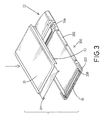
- FIG. 3 is an exploded perspective view of the casing of the present invention.
- FIG. 4 is a schematic view showing that the casing of the present invention is in process of assembly
- FIG. 5 is a schematic view showing that the casing of the present invention is in process of an alternative assembly manner
- FIG. 6 is a schematic cross sectional view showing that the hook is inserted into the L shaped hole.
- FIG. 7 is a schematic cross sectional view showing that the structure of the front sides of the upper casing and the lower casing.
- the casing for a PC cartridge is composed of an upper casing ( 10 ) and a lower casing ( 20 ), wherein a connector ( 30 ) is sandwiched between the upper casing ( 10 ) and the lower casing ( 20 ).
- the upper casing ( 10 ) has clamping sides ( 12 ) respectively formed on opposite sides of the upper casing ( 10 ), two hooks ( 14 ) respectively and oppositely formed on a front side of the upper casing ( 10 ).
- the lower casing ( 20 ) has a holding portion ( 22 ) formed on a rear of the lower casing ( 20 ) and a holding edge ( 222 ) formed on a front edge of the holding portion ( 22 ).
- the holding edge ( 222 ) is preferably inclined to a top face of the holding portion ( 22 ) in this embodiment.
- the lower casing ( 20 ) has a plastic frame ( 200 ) with a tilting side ( 202 ) formed on opposite sides of the frame ( 200 ), a pair of front positioning blocks ( 203 ) oppositely formed on the front side of the frame ( 200 ) and a pair of rear positioning blocks ( 204 ) oppositely formed on the rear side of the frame ( 200 ) and adjacent to the holding edge ( 222 ).
- Each of the front positioning blocks ( 203 ) has a cutout ( 206 ) defined to correspond to each other and an L shaped hole ( 208 ) corresponding to the hooks ( 14 ) of the upper casing ( 10 ). It is noted that the connector ( 30 ) has two protrusions ( 32 ) oppositely formed on a side of the connector ( 30 ) to correspond to the cutouts ( 206 ) of the front positioning blocks ( 203 ).
- the upper casing ( 10 ) is pressed downward to the lower casing ( 20 ).
- the clamping sides ( 12 ) of the upper casing ( 10 ) first engage with the tilting sides ( 202 ) of the lower casing ( 20 ) and are bent due to the inclined faces of the tilting sides ( 202 ). After the clamping sides ( 12 ) slide through the tilting sides ( 202 ), the clamping sides ( 12 ), due to the respective resilience from the material chosen to make the upper casing ( 10 ), securely clamp a bottom of the tilting sides ( 202 ).
- the hooks ( 14 ) extend into the L shaped holes ( 208 ) so that the engagement between the upper casing ( 10 ) and the lower casing ( 20 ) is secured.
- the user is able to hold the holding portion ( 22 ) to dispose the cartridge and grip the holding edge ( 222 ) to pull the cartridge out of the computer port without causing any damage to the casing.
- FIG. 5 With reference to FIG. 5 and referring to FIG. 6, another assembly of the casing may be adopted.
- the clamping sides ( 12 ) of the upper casing ( 10 ) are widened to clamp a bottom side of the front positioning blocks ( 203 ).
- the upper casing ( 10 ) is moved rearward to the holding portion ( 22 ) till the clamping sides ( 12 ) are located between the front positioning block ( 203 ) and the rear positioning block ( 204 ). Therefore, the clamping sides ( 12 ) of the upper casing ( 10 ) are able to clamp the bottom sides of the tilting sides ( 202 ) of the lower casing ( 20 ).
- the hooks ( 14 ) are received in the L shaped holes ( 208 ), which completes the assembly of the casing of the present invention.
- the upper casing ( 10 ) further has a first inclined face ( 16 ) formed on a front side of the upper casing ( 10 ) and relative to a top face of the upper casing ( 10 ).
- the lower casing further has a second inclined face ( 26 ) formed on a front side of the lower casing ( 20 ) and relative to a bottom face of the lower casing ( 20 ).
- the first inclined face ( 16 ) of the upper casing ( 10 ) and the second inclined face ( 26 ) of the lower casing ( 20 ) abut a flange ( 34 ) formed on a front side of the connector ( 30 ) so as to position the connector ( 30 ) inside the casing.
Abstract
A casing for a PC cartridge includes an upper casing having clamping sides respectively formed on opposite sides of the upper casing, two hooks respectively and oppositely formed on a front side of the upper casing, a lower casing securely connected to the upper casing and having a plastic frame with a tilting side formed on opposite sides of the frame, a pair of front positioning blocks oppositely formed on a front side of the frame and a pair of rear positioning blocks oppositely formed on a rear side of the frame, wherein each of the front positioning blocks has an L shaped hole corresponding to the hooks of the upper casing. Each clamping side clamping a bottom of a corresponding one of the tilting sides and the hooks being received in the L shaped holes secure engagement between the upper casing and the lower casing.
Description
1. Field of the Invention
The present invention relates to a casing, and more particularly to a casing for a PC cartridge. The casing enables the user to have a firm grip without deforming the shape of the casing.
2. Description of Related Art
A conventional PC cartridge is somewhat like a business card and has therein a connector for connection with a connecting port on a computer. The conventional cartridge usually is composed of an upper casing, a lower casing and a frame made of plastic to surround a joint between the upper casing and the lower casing. However, because the requirements for such a PC cartridge are being light, thin, short and small, the material chosen for making the casing is mainly a light-weight, thin plate. Furthermore, the connector on the open end of the PC cartridge is short such that a large room in the PC cartridge is empty and there is nothing to support the structural integrity. Therefore, when the user is travelling with the PC cartridge, the casing of the cartridge is easily deformed and thus damaged. Despite the damage caused from travelling, when the user is trying to pull off the PC cartridge from the computer port, the holding of the casing of the cartridge so as to remove the cartridge from the computer will cause serious deformation to the casing.
When there is a deformation, opposite sides of the cartridge will easily flip over and thus the user is easily cut by accident.
To overcome the shortcomings, the present invention tends to provide an improved casing for a PC cartridge to mitigate and obviate the aforementioned problems.
The primary objective of the present invention is to provide a casing for a PC cartridge. The casing has a holding portion provided at the rear of the casing such that the user is able to hold the holding portion to dispose the cartridge as required without casing any damage to the casing.
Another objective of the present invention is to provide a holding edge formed on a front side of the holding portion. Therefore, the user is able to use the holding edge to pull the cartridge out of the computer port without deforming the casing.
Still another objective of the present invention is to provide a casing having a hook formed on a front edge of an upper casing and an L shaped hole defined in a front edge of a lower casing to correspond to the hook of the upper casing. Further, a clamping side is formed on opposite sides of the upper casing and a tilting side is formed on opposite sides of the lower casing. Therefore, when the upper casing and the lower casing are combined, the combination between the hook and the L shaped hole and the combination between the clamping side and the tilting side are able to secure the engagement between the upper casing and the lower casing.
Other objects, advantages and novel features of the invention will become more apparent from the following detailed description when taken in conjunction with the accompanying drawings.
FIG. 1 is a perspective view of the PC cartridge;
FIG. 2 is an exploded perspective view of the cartridge;
FIG. 3 is an exploded perspective view of the casing of the present invention;
FIG. 4 is a schematic view showing that the casing of the present invention is in process of assembly;
FIG. 5 is a schematic view showing that the casing of the present invention is in process of an alternative assembly manner;
FIG. 6 is a schematic cross sectional view showing that the hook is inserted into the L shaped hole; and
FIG. 7 is a schematic cross sectional view showing that the structure of the front sides of the upper casing and the lower casing.
With reference to FIGS. 1 and 2, the casing for a PC cartridge is composed of an upper casing (10) and a lower casing (20), wherein a connector (30) is sandwiched between the upper casing (10) and the lower casing (20).
The upper casing (10) has clamping sides (12) respectively formed on opposite sides of the upper casing (10), two hooks (14) respectively and oppositely formed on a front side of the upper casing (10).
The lower casing (20) has a holding portion (22) formed on a rear of the lower casing (20) and a holding edge (222) formed on a front edge of the holding portion (22). The holding edge (222) is preferably inclined to a top face of the holding portion (22) in this embodiment. The lower casing (20) has a plastic frame (200) with a tilting side (202) formed on opposite sides of the frame (200), a pair of front positioning blocks (203) oppositely formed on the front side of the frame (200) and a pair of rear positioning blocks (204) oppositely formed on the rear side of the frame (200) and adjacent to the holding edge (222). Each of the front positioning blocks (203) has a cutout (206) defined to correspond to each other and an L shaped hole (208) corresponding to the hooks (14) of the upper casing (10). It is noted that the connector (30) has two protrusions (32) oppositely formed on a side of the connector (30) to correspond to the cutouts (206) of the front positioning blocks (203).
With reference to FIGS. 3, 4 and 6, during assembly of the casing of the present invention, the upper casing (10) is pressed downward to the lower casing (20). The clamping sides (12) of the upper casing (10) first engage with the tilting sides (202) of the lower casing (20) and are bent due to the inclined faces of the tilting sides (202). After the clamping sides (12) slide through the tilting sides (202), the clamping sides (12), due to the respective resilience from the material chosen to make the upper casing (10), securely clamp a bottom of the tilting sides (202).
Further, when the upper casing (10) is moving toward the lower casing (20), the hooks (14) extend into the L shaped holes (208) so that the engagement between the upper casing (10) and the lower casing (20) is secured.
With the structure as described, the user is able to hold the holding portion (22) to dispose the cartridge and grip the holding edge (222) to pull the cartridge out of the computer port without causing any damage to the casing.
With reference to FIG. 5 and referring to FIG. 6, another assembly of the casing may be adopted. When in assembly, the clamping sides (12) of the upper casing (10) are widened to clamp a bottom side of the front positioning blocks (203). Then the upper casing (10) is moved rearward to the holding portion (22) till the clamping sides (12) are located between the front positioning block (203) and the rear positioning block (204). Therefore, the clamping sides (12) of the upper casing (10) are able to clamp the bottom sides of the tilting sides (202) of the lower casing (20). Meanwhile, the hooks (14) are received in the L shaped holes (208), which completes the assembly of the casing of the present invention.
With reference to FIG. 7 and taking reference of FIG. 2, the upper casing (10) further has a first inclined face (16) formed on a front side of the upper casing (10) and relative to a top face of the upper casing (10). The lower casing further has a second inclined face (26) formed on a front side of the lower casing (20) and relative to a bottom face of the lower casing (20). Therefore, when the assembly of the casing is finished, the first inclined face (16) of the upper casing (10) and the second inclined face (26) of the lower casing (20) abut a flange (34) formed on a front side of the connector (30) so as to position the connector (30) inside the casing.
It is to be understood, however, that even though numerous characteristics and advantages of the present invention have been set forth in the foregoing description, together with details of the structure and function of the invention, the disclosure is illustrative only, and changes may be made in detail, especially in matters of shape, size, and arrangement of parts within the principles of the invention to the full extent indicated by the broad general meaning of the terms in which the appended claims are expressed.
Claims (1)
1. A casing for a PC cartridge, the casing comprising:
an upper casing having clamping sides respectively formed on opposite sides of the upper casing, two hooks respectively and oppositely formed on a front side of the upper casing;
a lower casing securely connected to the upper casing and having a plastic frame with a tilting side formed on opposite sides of the frame, a pair of front positioning blocks oppositely formed on a front side of the frame, a holding portion formed on a rear of the lower casing, a holding edge formed on a front edge of the holding portion, the holding edge being inclined to a top face of the holding portion and a pair of rear positioning blocks oppositely formed on a rear side of the frame, wherein each of the front positioning blocks has an L shaped hole corresponding to the hooks of the upper casing,
wherein each of the front positioning blocks has a cutout defined to face each other and being adapted to receive therein a protrusion formed on opposite sides of a connector sandwiched between the upper casing and the lower casing,
wherein the upper casing further has a first inclined face formed on a front side of the upper casing and relative to a top face of the upper casing, the lower casing further has a second inclined face formed on a front side of the lower casing and relative to a bottom face of the lower casing,
whereby the first inclined face of the upper casing and the second inclined face of the lower casing are adapted to abut a flange of the connector so as to position the connector inside the casing, and
each clamping side clamping a bottom of a corresponding one of the tilting sides and the hooks being received in the L shaped holes to secure engagement between the upper casing and the lower casing.
Priority Applications (1)
| Application Number | Priority Date | Filing Date | Title |
|---|---|---|---|
| US10/197,500 US6639805B1 (en) | 2002-07-18 | 2002-07-18 | Casing for a PC cartridge |
Applications Claiming Priority (1)
| Application Number | Priority Date | Filing Date | Title |
|---|---|---|---|
| US10/197,500 US6639805B1 (en) | 2002-07-18 | 2002-07-18 | Casing for a PC cartridge |
Publications (1)
| Publication Number | Publication Date |
|---|---|
| US6639805B1 true US6639805B1 (en) | 2003-10-28 |
Family
ID=29250197
Family Applications (1)
| Application Number | Title | Priority Date | Filing Date |
|---|---|---|---|
| US10/197,500 Expired - Fee Related US6639805B1 (en) | 2002-07-18 | 2002-07-18 | Casing for a PC cartridge |
Country Status (1)
| Country | Link |
|---|---|
| US (1) | US6639805B1 (en) |
Cited By (4)
| Publication number | Priority date | Publication date | Assignee | Title |
|---|---|---|---|---|
| US20040266231A1 (en) * | 2003-06-30 | 2004-12-30 | Costello Brian Patrick | Electrical card connector |
| US20050195580A1 (en) * | 2004-03-08 | 2005-09-08 | Frank Lin | Electronic card |
| US20050207126A1 (en) * | 2003-12-22 | 2005-09-22 | Cai-Ting Gu | Packaged structure of PCMCIA cartridge |
| US20180076551A1 (en) * | 2015-04-14 | 2018-03-15 | Mitsubishi Electric Corporation | Multipole connector, connector device, case, and method for connecting cable to multipole connector |
Citations (4)
| Publication number | Priority date | Publication date | Assignee | Title |
|---|---|---|---|---|
| US5339222A (en) * | 1993-04-06 | 1994-08-16 | The Whitaker Corporation | Shielded printed circuit card holder |
| US5502617A (en) * | 1992-11-13 | 1996-03-26 | Seiko Epson Corporation | Electronic device having a flat, card-like casing enclosing components for a complete computer system |
| US5547397A (en) * | 1993-12-08 | 1996-08-20 | Honda Tsushin Kogyo Kabushiki Kaisha | PC card connector and PC card |
| US6315205B1 (en) * | 1999-07-06 | 2001-11-13 | Itt Manufacturing Enterprises, Inc. | Adaptor for smart card |
-
2002
- 2002-07-18 US US10/197,500 patent/US6639805B1/en not_active Expired - Fee Related
Patent Citations (4)
| Publication number | Priority date | Publication date | Assignee | Title |
|---|---|---|---|---|
| US5502617A (en) * | 1992-11-13 | 1996-03-26 | Seiko Epson Corporation | Electronic device having a flat, card-like casing enclosing components for a complete computer system |
| US5339222A (en) * | 1993-04-06 | 1994-08-16 | The Whitaker Corporation | Shielded printed circuit card holder |
| US5547397A (en) * | 1993-12-08 | 1996-08-20 | Honda Tsushin Kogyo Kabushiki Kaisha | PC card connector and PC card |
| US6315205B1 (en) * | 1999-07-06 | 2001-11-13 | Itt Manufacturing Enterprises, Inc. | Adaptor for smart card |
Cited By (6)
| Publication number | Priority date | Publication date | Assignee | Title |
|---|---|---|---|---|
| US20040266231A1 (en) * | 2003-06-30 | 2004-12-30 | Costello Brian Patrick | Electrical card connector |
| US6932626B2 (en) * | 2003-06-30 | 2005-08-23 | Tyco Electronics Corporation | Electrical card connector |
| US20050207126A1 (en) * | 2003-12-22 | 2005-09-22 | Cai-Ting Gu | Packaged structure of PCMCIA cartridge |
| US7019980B2 (en) * | 2003-12-22 | 2006-03-28 | Cai-Ting Gu | Packaged structure of PCMCIA cartridge |
| US20050195580A1 (en) * | 2004-03-08 | 2005-09-08 | Frank Lin | Electronic card |
| US20180076551A1 (en) * | 2015-04-14 | 2018-03-15 | Mitsubishi Electric Corporation | Multipole connector, connector device, case, and method for connecting cable to multipole connector |
Similar Documents
| Publication | Publication Date | Title |
|---|---|---|
| US6317315B1 (en) | Portable computer with detachable display module | |
| US5178556A (en) | Computer plug connector fastening mechanism | |
| US5730342A (en) | Mobile telephone fastening | |
| US6679379B1 (en) | Tool suspension device | |
| US7233500B2 (en) | Card connector | |
| US6059384A (en) | Computer housing and foot member arrangement for a vertical computer | |
| US5253440A (en) | Structure of a picture frame | |
| CN101404860A (en) | Strap attachable mobile device | |
| US7035117B2 (en) | Expansion card mounting apparatus | |
| US20080074018A1 (en) | Mounting apparatus for data storage device | |
| US6639805B1 (en) | Casing for a PC cartridge | |
| US5716228A (en) | Computer plug connector fastening mechanism | |
| US6040540A (en) | Keyswitch structure | |
| US7164080B2 (en) | Bezel mounting assembly | |
| US20080239633A1 (en) | Housing mechanism with hook for portable electronic device | |
| US7001216B1 (en) | Casing for a modular socket | |
| US7097467B2 (en) | Dustproof plate fixture for an electrical connector | |
| JP2005150666A (en) | Case top-cover attachment and detachment device | |
| US5603528A (en) | Photo album usable as a picture stand | |
| CN215529070U (en) | Flat mobile phone clamp | |
| JP2006263066A (en) | Tiepin | |
| CN214851379U (en) | Omnibearing protective shell | |
| US20050048819A1 (en) | Back cartridge coupling structure | |
| JP3562253B2 (en) | Coupling device | |
| CN215455967U (en) | Easy-to-detach certificate card sleeve |
Legal Events
| Date | Code | Title | Description |
|---|---|---|---|
| REMI | Maintenance fee reminder mailed | ||
| LAPS | Lapse for failure to pay maintenance fees | ||
| STCH | Information on status: patent discontinuation |
Free format text: PATENT EXPIRED DUE TO NONPAYMENT OF MAINTENANCE FEES UNDER 37 CFR 1.362 |
|
| FP | Lapsed due to failure to pay maintenance fee |
Effective date: 20071028 |