US6662052B1 - Method and system for neuromodulation therapy using external stimulator with wireless communication capabilites - Google Patents
Method and system for neuromodulation therapy using external stimulator with wireless communication capabilites Download PDFInfo
- Publication number
- US6662052B1 US6662052B1 US09/837,565 US83756501A US6662052B1 US 6662052 B1 US6662052 B1 US 6662052B1 US 83756501 A US83756501 A US 83756501A US 6662052 B1 US6662052 B1 US 6662052B1
- Authority
- US
- United States
- Prior art keywords
- stimulator
- external
- server
- programs
- therapy
- Prior art date
- Legal status (The legal status is an assumption and is not a legal conclusion. Google has not performed a legal analysis and makes no representation as to the accuracy of the status listed.)
- Expired - Fee Related, expires
Links
Images


Classifications
-
- A—HUMAN NECESSITIES
- A61—MEDICAL OR VETERINARY SCIENCE; HYGIENE
- A61N—ELECTROTHERAPY; MAGNETOTHERAPY; RADIATION THERAPY; ULTRASOUND THERAPY
- A61N1/00—Electrotherapy; Circuits therefor
- A61N1/18—Applying electric currents by contact electrodes
- A61N1/32—Applying electric currents by contact electrodes alternating or intermittent currents
- A61N1/36—Applying electric currents by contact electrodes alternating or intermittent currents for stimulation
- A61N1/36014—External stimulators, e.g. with patch electrodes
- A61N1/36017—External stimulators, e.g. with patch electrodes with leads or electrodes penetrating the skin
-
- A—HUMAN NECESSITIES
- A61—MEDICAL OR VETERINARY SCIENCE; HYGIENE
- A61N—ELECTROTHERAPY; MAGNETOTHERAPY; RADIATION THERAPY; ULTRASOUND THERAPY
- A61N1/00—Electrotherapy; Circuits therefor
- A61N1/18—Applying electric currents by contact electrodes
- A61N1/32—Applying electric currents by contact electrodes alternating or intermittent currents
- A61N1/36—Applying electric currents by contact electrodes alternating or intermittent currents for stimulation
- A61N1/372—Arrangements in connection with the implantation of stimulators
- A61N1/37211—Means for communicating with stimulators
- A61N1/37252—Details of algorithms or data aspects of communication system, e.g. handshaking, transmitting specific data or segmenting data
- A61N1/37282—Details of algorithms or data aspects of communication system, e.g. handshaking, transmitting specific data or segmenting data characterised by communication with experts in remote locations using a network
-
- A—HUMAN NECESSITIES
- A61—MEDICAL OR VETERINARY SCIENCE; HYGIENE
- A61N—ELECTROTHERAPY; MAGNETOTHERAPY; RADIATION THERAPY; ULTRASOUND THERAPY
- A61N1/00—Electrotherapy; Circuits therefor
- A61N1/18—Applying electric currents by contact electrodes
- A61N1/32—Applying electric currents by contact electrodes alternating or intermittent currents
- A61N1/36—Applying electric currents by contact electrodes alternating or intermittent currents for stimulation
- A61N1/36007—Applying electric currents by contact electrodes alternating or intermittent currents for stimulation of urogenital or gastrointestinal organs, e.g. for incontinence control
-
- A—HUMAN NECESSITIES
- A61—MEDICAL OR VETERINARY SCIENCE; HYGIENE
- A61N—ELECTROTHERAPY; MAGNETOTHERAPY; RADIATION THERAPY; ULTRASOUND THERAPY
- A61N1/00—Electrotherapy; Circuits therefor
- A61N1/18—Applying electric currents by contact electrodes
- A61N1/32—Applying electric currents by contact electrodes alternating or intermittent currents
- A61N1/36—Applying electric currents by contact electrodes alternating or intermittent currents for stimulation
- A61N1/3605—Implantable neurostimulators for stimulating central or peripheral nerve system
- A61N1/3606—Implantable neurostimulators for stimulating central or peripheral nerve system adapted for a particular treatment
- A61N1/36082—Cognitive or psychiatric applications, e.g. dementia or Alzheimer's disease
-
- A—HUMAN NECESSITIES
- A61—MEDICAL OR VETERINARY SCIENCE; HYGIENE
- A61N—ELECTROTHERAPY; MAGNETOTHERAPY; RADIATION THERAPY; ULTRASOUND THERAPY
- A61N1/00—Electrotherapy; Circuits therefor
- A61N1/18—Applying electric currents by contact electrodes
- A61N1/32—Applying electric currents by contact electrodes alternating or intermittent currents
- A61N1/36—Applying electric currents by contact electrodes alternating or intermittent currents for stimulation
- A61N1/372—Arrangements in connection with the implantation of stimulators
- A61N1/37211—Means for communicating with stimulators
- A61N1/37217—Means for communicating with stimulators characterised by the communication link, e.g. acoustic or tactile
- A61N1/37223—Circuits for electromagnetic coupling
Definitions
- the present invention relates to wireless communication capability of an external stimulator for neuromodulation, more specifically an external stimulator for neuromodulation therapy for urological, neurological, and neuropsychiatric disorders, having two-way wireless communication through a server.
- This invention is directed to remotely controlling the stimulation therapy for these disorders, utilizing an implanted lead-receiver, and an external stimulator with predetermined (pre-packaged) stimulation programs.
- Some of the predetermined programs may be manually operated, but some programs are locked-out to the patient. These patient locked-out programs can be accessed by the physician either in person via a password or remotely.
- the remote activation of these programs is via the wireless Internet server, communicating with an external controller using a wireless interface.
- a physician situated remotely is also able to activate predetermined programs, as well as, interrogate the external stimulation devices of his/her patients.
- a physician is able to change which programs are accessible to the patient.
- FIG. 1 shows a sagittal section of the human female pelvis showing the bladder 10 and urethra 13 , in relation to other anatomic structures.
- Urinary continence requires a relaxed bladder during the collecting phase and permanent closure of the urethra 13 , whereas at micturition (urination), an intravesical pressure above the opening pressure of the simultaneously relaxing urethra has to be generated.
- These functions of the bladder 10 and urethra 13 are centrally coordinated and non-separable.
- the sensation of urge is mediated by slowly adapting mechanoreceptors in the bladder wall and the same receptors provide the triggering signal for micturition and the main driving force for a sustained micturition contraction.
- the mechanoreceptors are, technically speaking, tension receptors. It has been found that they respond equally well to tension increases induced passively by bladder filling and those induced actively by a detrusor contraction. These receptors have high dynamic sensitivity and are easily activated by external pressure transients, as may occur during coughing or tapping of the abdominal wall. Their faithful response to active changes in bladder pressure is well illustrated.
- the mechanorecptors When sufficiently activated, the mechanorecptors trigger a coordinated micturition reflex via a center in the upper pons 88 , as depicted schematically in FIG. 2 .
- the reflex detrusor 92 (muscle in the wall of the urinary bladder) contraction generates an increased bladder pressure and an even stronger activation of the mechanoreceptors. Their activity in turn reinforces the pelvic motor output to the bladder 10 , which leads to a further increase in pressure and more receptor activation and so on. In this way, the detrusor 92 contraction is to a large extent self generating once initiated.
- Such a control mechanism usually is referred to as a positive feedback, and it may explain the typical all-or-nothing behavior of the parasympathetic motor output to the bladder 10 .
- a great advantage of the positive feedback system is that it ascertains a complete emptying of the bladder 10 during micturition. As long as there is any fluid left in the lumen, the intravesical pressure will be maintained above the threshold for the mechanoreceptors and thus provide a continuous driving force for the detrusor 92 .
- a drawback with this system is that it can easily become unstable. Any stimulus that elicits a small burst of impulses in mechanoreceptor afferents may trigger a fullblown micturition reflex. To prevent this from happening during the filling phase, the neuronal system controlling the bladder is equipped with several safety devices both at the spinal and supraspinal levels.
- the best-known spinal mechanism is the reflex control of the striated urethral sphincter 90 , which increases its activity in response to bladder mechanoreceptor activation during filling.
- An analogous mechanism is Edvardsen's reflex, which involves machanoreceptor activation of inhibitory sympathetic neurons to the bladder.
- the sympathetic efferents have a dual inhibitory effect, acting both at the postganglionic neurons in the vesical ganglia and directly on the detrusor muscle of the bladder 92 .
- the sphincter and sympathetic reflexes are automatically turned off at the spinal cord level during a normal micturition.
- At the supraspinal level there are inhibitory connections from the cerebral cortex and hypothalamus to the pontine micturition center. The pathways are involved in the voluntry control of continance.
- Other inhibitory systems seem to orignate from the pontine and medullary parts of the brainstem with at least partly descending connections.
- Bladder over-activity and urinary urge incontinance may result from an imbalance between the excitatory positive feedback system of the bladder 10 and inhibitory control systems causing a hyperexcitable voiding reflex. Such an imbalance may occur after macroscopic lesions at many sites in the nervous system or after minor functional disturbances of the excitatory or inhibitory circuits. Urge incontinence due to detrusor instability seldom disappears spontaneoulsly. The symptomatic pattern also usually is consistent over long periods.
- Phasic detrusor instability is characterized by normal or increased bladder sensation, phasic bladder contractions occurring spontaneously during bladder filling or on provocation, such as by rapid filling, coughing, or jumping. This condition results from a minor imbalance between the bladder's positive-feedback system and the spinal inhibitory mechanisms.
- Uninhibited overactive bladder is characterized by loss of voluntary control of micturition and impairment of bladder sensation. The first sensation of filling is experienced at a normal or lowered volume and is almost immediately followed by involuntary micturition.
- the patient does not experience a desire to void until she/he is already voiding with a sustained detrusor contraction and a concomitant relaxation of the urethra, i.e., a well-coordinated micturitiori reflex. At this stage, she/he is unable to interrupt micturition voluntarily.
- the sensory disturbance of these subjects is not in the periphery, at the level of bladder mechanoreceptors, as the micturition reflex occurs at normal or even small bladder volumes. More likely, the suprapontine sensory projection to the cortex is affected. Such a site is consistent with the coordinated micturition and the lack of voluntary control.
- the uninhibited overactive bladder is present in neurogenic dysfunction.
- Neuromodulation is a technique that uses electrical stimulation of the sacral nerves 85 , (a general diagram of spinal cord and sacral nerves 85 is shown in FIG. 3 ).
- the aim of this treatment modality is to achieve detrusor 92 inhibition by chronic electrical stimulation of afferent somatic sacral nerve fibers 85 via implanted electrodes connected to a subcutaneously placed pulse generation means.
- the procedure consists of placing electrodes 61 , 62 in one of the sacral foramen as close to the pelvic plexus and pudendal nerve as possible and connecting the lead 59 with a means for electrical stimulation 49 .
- An anchoring sleeve 15 may be used for securing the lead.
- a neurophysiological explanation for the effectiveness of this treatment modality in detrusor instability is based on animal experiments and electrophysiological studies in humans.
- Electrical stimulation for the treatment of urinary incontinence has evolved over the past 40 years.
- the mechanism of action of electrical stimulation was investigated initially in animal models. Over 100 years ago, Griffiths demonstrated relaxation of a contracted detrusor during stimulation of the proximal pudendal nerve in the cat model and further work clarified the role of pudendal afferents in relation of the detrusor 92 .
- Spinal inhibitory systems capable of interrupting a detrusor 92 contraction can be activated by electrical stimulation of afferent anorectal branhes of the pelvic nerve, afferent sensory fibers in the pudendal nerve and muscle afferents from the limbs.
- the effectiveness of neuromodulation in humans has been objectively demonstrated by urodynamic improvement, expecially in light of the fact that such effects have not been noted in drug trials.
- Neuromodulation also acts on neural reflexes but does so internally by stimulation of the sacral nerves 85 .
- Sacral nerve 85 stimulation is based on research dedicated to the understanding of the voiding reflex as well as the role and influence of the sacral nerves 85 on voiding behavior. This research led to the development of a technique to modulate dysfunctional voiding behavior through sacral nerve stimulation. It is thought that sacral nerve stimulation induces reflex mediated inhibitory effects on the detrusor 92 through afferent and/or efferent stimulation of the sacral nerves 85 . Even though the precise mechanism of action of electrical stimulation in humans is not fully understood, it has been shown that sensory input traveling through the pudendal nerve can inhibit detrusor activity in humans. Most experts believe that non-implanted electrical stimulation works by stimulating the pudendal nerve afferents, with the efferent outflow causing contraction of the striated pelvic musculature. There is also inhibition of inappropriate detrusor activity.
- the rationale for neuromodulation in the treatment of such patients is the observation that stimulation of the sacral nerves via electrical stimulation can inhibit inappropriate neural reflex behavior.
- VNS vagus nerve stimulation
- Vagus nerve stimulation and the profound effects of electrical stimulation of the vagus nerve on central nervous system (CNS) activity, extends back to the 1930's.
- Medical studies in clinical neurobiology have advanced our understanding of anatomic and physiologic basis of the beneficial neurologic effects of chronic vagus nerve stimulation.
- the vagus nerve 54 is the 10th cranial nerve, and is a direct extension of the brain.
- FIG. 5 shows a diagram of the brain and spinal cord, with its relationship to the vagus nerve 54 and the nucleus tractus solitarius 14 .
- FIG. 6 shows a diagram of base of the brain, showing the relationship of the vagus nerve with the other eleven cranial nerves.
- Vagus nerve stimulation is a means of directly affecting central function and is less invasive than deep brain stimulation (DBS).
- DBS deep brain stimulation
- cranial nerves have both afferent pathway 19 (inward conducting nerve fibers which convey impulses toward the brain) and efferent pathway 21 (outward conducting nerve fibers which convey impulses to an effector).
- the vagus nerve 54 is composed of 80% afferent sensory fibers carrying information to the brain from the head, neck, thorax, and abdomen.
- the sensory afferent cell bodies of the vagus reside in the nodose ganglion and relays information to the nucleus tractus solitarius (NTS).
- the nucleus of the solitary tract 14 relays this incoming sensory information to the rest of the brain through three main pathways; 1) an autonomic feedback loop, 2) direct projection to the reticular formation in the medulla, and 3) ascending projections to the forebrain largely through the parabrachial nucleus 20 (PBN) and the locus ceruleius 22 (LC).
- the PBN sits adjacent to the LC (FIG. 5 ).
- the PBN/LC sends direct connections to every level of the forebrain, including the hypothalamus 26 , and several thalamic regions that control the insula and orbitofrontal 28 and prefrontal cortices.
- the PBN/LC has direct connections to the amygdala 27 and the bed nucleus of the stria terminalis—structures that are implicated in emotion recognition and mood regulation.
- incoming sensory (afferent) connections of the vagus nerve 54 provide direct projections to many of the brain regions implicated in neurologic and neuropsychiatric disorders. These connections reveal how vagus nerve 54 stimulation is a portal to the brainstem and connected regions. These circuits likely account for the beneficial neurologic and neuropsychiatric effects of the vag us nerve stimulation.
- Increased activity of the vagus nerve 54 is also associated with the release of more serotonin in the brain.
- Much of the pharmacologic therapy for treatment of migraines is aimed at increasing the levels of serotonin in the brain. Therefore, non-pharmacologic therapy of electrically stimulating the vagus nerve 54 would have benefits for adjunct treatment of migraines also.
- the vagus nerve 54 provides an easily accessible, peripheral route to modulate central nervous system (CNS) function. Other cranial nerves can be used for the same purpose, but the vagus nerve 54 is preferred because of its easy accessibility.
- VN vagus nerves
- Each vagus nerve is encased in the carotid sheath along with the carotid artery and jugular vein.
- the innervation of the right and left vagus nerves is different.
- the innervation of the right vagus nerve is such that stimulating it results in profound bradycardia (slowing of the heart rate).
- the left vagus nerve has some innervation to the heart, but mostly innervates the visceral organs such as the gastrointestinal tract. It is known that stimulation of the left vagus nerve does not cause any significant deleterious side effects.
- the vagus nerve 54 may have approximately 100,000 fibers of the three different types, each carrying signals. Each axon or fiber (shown in FIG. 9A) of that nerve conducts only in one direction, in normal circumstances.
- the A and B fibers are myelinated (i.e., have a myelin sheath, constituting a substance largely composed of fat, as shown in FIG. 9 B), whereas the C fibers are unmyelinated.
- the diameters of group A and group B fibers include the thickness of the myelin sheaths.
- Group A is further subdivided into alpha, beta, gamma, and delta fibers in decreasing order of size. There is some overlapping of the diameters of the A, B, and C groups because physiological properties, especially the form of the action potential, are taken into consideration when defining the groups.
- the smallest fibers (group C) are unmyelinated and have the slowest conduction rate, whereas the myelinated fibers of group B and group A exhibit rates of conduction that progressively increase with diameter.
- Group B fibers are not present in the nerves of the limbs; they occur in white rami and some cranial nerves.
- myelinated fibers are typically larger, conduct faster, have very low stimulation thresholds, and exhibit a particular strength-duration curve or respond to a specific pulse width versus amplitude for stimulation.
- the A and B fibers can be stimulated with relatively narrow pulse widths, from 50 to 200 microseconds ( ⁇ s), for example.
- the A fiber conducts slightly faster than the B fiber and has a slightly lower threshold.
- the C fibers are very small, conduct electrical signals very slowly, and have high stimulation thresholds typically requiring a wider pulse width (300-1,000 ⁇ s) and a higher amplitude for activation. Selective stimulation of only A and B fibers is readily accomplished.
- the vagus nerve is composed of somatic and visceral afferents and efferents.
- nerve stimulation activates signals in both directions (bi-directionally). It is possible, however, through the use of special electrodes and waveforms, to selectively stimulate a nerve in one direction only (unidirectionally).
- the vast majority of vagus nerve fibers are C fibers, and a majority are visceral afferents having cell bodies lying in masses or ganglia in the skull.
- the central projections terminate largely in the nucleus of the solitary tract 14 which sends fibers to various regions of the brain (e.g., the hypothalamus 26 , thalamus 25 , and amygdala 27 ).
- vagus nerve 54 stimulation for relief of neurological disorders is that vagus visceral afferents have a diffuse central nervous system (CNS) projection, and activation of these pathways has a widespread effect on neuronal excitability.
- CNS central nervous system
- One form of prior art neuromodulation therapy is generally directed to an implantable pulse generator system.
- the communication is generally performed via a modified personnel computer and a programming wand.
- Prior art wireless communication for medical stimulation devices includes, U.S. Pat. No. 5,759,199 (Snell et al) which is directed to ambulatory monitoring and programming of an implantable medical device.
- the system disclosed enables wireless communication between the programmer/analyzer and the implantable medical device.
- U.S. Pat. No. 5,978,713 (Prutchi) is primarily directed to telemetry of information from an implant that is generated from atrial and ventricular endocardial leads to an external programmer.
- U.S. Pat. No. 5,997,476 (Brown) is directed to communicating information to an individual and for remotely monitoring the individual.
- the system of the '476 patent includes a server and a remote interface for entering in the server a set of queries to be answered by the individual.
- the disclosed system includes a remotely programmable apparatus connected to the server via a communication network.
- U.S. Pat. No. 5,458,122 (Hethuin) is directed to the wireless transmission of surface EKG signals to a remote location via transmission equipment components held onto the body of the patient.
- U.S. Pat. Nos. 4,702,254, 4,867,164 and 5,025,807 generally disclose animal research and experimentation related to epilepsy and the like and are directed to stimulating the vagus nerve by using “pacemaker-like” technology, such as an implantable pulse generator.
- the pacemaker technology concept consists of a stimulating lead connected to a pulse generator (containing the circuitry and DC power source) implanted subcutaneous or submuscularly, somewhere in the pectoral or axillary region, with an external personal computer (PC) based programmer. Once the pulse generator is programmed for the patient, the fully functional circuitry and power source are fully implanted within the patient's body.
- PC personal computer
- U.S. Pat. No. 5,215,086 (Terry, Jr. et al) is directed to the use of implantable pulse generator technology for treating and controlling migraine, by stimulating the vagus nerve of a patient by an implantable lead and “pacemaker like” device to alleviate the migraine attack.
- U.S. Pat. No. 4,771,779 (Tanagho et al) is directed to a system for controlling bladder evacuation, which consists of multiple implanted stimulation systems having electrodes positioned on nerves controlling external sphincter and bladder functions, and electronic control system which transmit to the stimulation systems.
- the interaction between stimulating the bladder and external sphincter can be controlled.
- the present invention is directed to a system and method for remotely controlling the neuromodulation therapy of urological, neurological, neuropsychiatric disorders.
- the system comprises an implantable lead-receiver, and an external stimulator with the primary coil on the same packaging.
- the implanted lead-receiver and the external stimulator are inductively coupled.
- the external stimulator has two way wireless communication capabilities. This wireless capability is used primarily to exchange the programmed parameters in the stimulator to remotely control the stimulation therapy.
- An implanted lead-receiver contains electrodes in contact with the nerve to be stimulated, passive circuitry, and a secondary coil for coupling with an external (primary) coil.
- the external stimulator comprises a unit, which is about the size of a small cardiac pacemaker on which a coil and pulse generator circuitry with a replaceable power source (battery) module are mounted.
- the pulse generator battery is the disposable component of the system.
- An indicator on the external stimulator indicates the battery status, so that the battery can be routinely replaced.
- Proximity sensing circuitry aids in the optimal placement of the external stimulator coil, in close proximity to the secondary (implanted) coil.
- the combination of a magnet in the implanted lead-receiver and sensors mounted in the external generator provide means for proximity sensing and feedback control of pulse stimulus outputs.
- the feedback circuitry adjusts the output of pulses to ensure proper delivery of electrical stimulation therapy as the primary (external) and secondary (implanted) coils change orientation relative to each other.
- the external stimulator contains a limited number of predetermined (pre-packaged) programs consisting of unique combinations of parameters such as pulse amplitude, pulse width, frequency of stimulation, on-time, and off-time.
- the external stimulator communicates wirelessly with a remote server, using a communication protocol such as wireless application protocol (WAP).
- WAP wireless application protocol
- the physician can change the therapy to another predetermined program by communicating with the server.
- the server in turn communicates with the neurostimulator (external pulse generator).
- the physician can also make relatively “small” variations to existing programs for improvements in therapy being delivered.
- the communication between physician's handheld device and server, and communication between the server and external neurostimulator utilizes the wireless application protocol (WAP).
- WAP wireless application protocol
- a physician at a remote location is able to check the stimulation program execution status of his/her patient population by obtaining a summary report, using secure communication.
- the physician is able to set up long-term schedules of stimulation therapy for their patient population, through wireless communication with the server.
- the server in turn communicates these programs to the neuro-stimulator.
- a physician may program an Alzheimer's patient to a stimulation program for two weeks, and program an epilepsy patient to long-term “on”, “off” stimulation therapy.
- Each schedule is securely maintained on the server, and is editable by the physician, and can get uploaded to the patient's stimulator device at a scheduled time.
- Each device issued to a patient has a unique identification key in order to guarantee secure communication between the wireless server and device.
- FIG. 1 shows a diagram of the sagittal section of the female pelvis, showing the relationship between various anatomic structures.
- FIG. 2 is a schematic diagram showing physiological control of micturition.
- FIG. 3 is a diagram showing anatomic relationships of the spinal nerves and sacral plexus.
- FIG. 4 is a schematic diagram of the sacral region showing electrodes in sacral foraman, and placement of the lead-receiver.
- FIG. 5 is a diagram of the lateral view of the brain and spinal cord, with its relationship to the vagus nerve.
- FIG. 6 is a diagram of the base of brain showing the relationship of vagus nerve to the other cranial nerves.
- FIG. 7 is a diagram of the brain showing afferent and efferent pathways.
- FIG. 8 is a schematic showing relationship of Nucleus of the Solitary Track and how it relays information to other parts of the brain.
- FIG. 9A is a diagram of a nerve fiber.
- FIG. 9B is a diagram of a nerve fiber showing layers of myelin.
- FIG. 10A is a schematic diagram showing the concept of the invention.
- the placement of the external stimulator is on the upper part of the chest for neurological, and neuropsychiatric applications.
- FIG. 10B is a schematic diagram showing the concept of the invention.
- the placement of the external stimulator is on the lower abdomen for urge incontinance applications.
- FIG. 11 is a diagram showing the front-view and side-view of the external stimulator and patch.
- FIG. 12 is a diagram showing an alternative embodiment of an external pulse generator with wire connection to the supercutaneous coil.
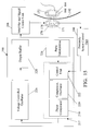
- FIG. 13 shows the concept block diagram of the invention in the preferred embodiment.
- FIG. 14A is a diagram showing the primary and secondary coils separated by skin, and the components of the external stimulator.
- FIG. 14B is a schematic diagram showing the programming station interfaced to the external stimulator.
- FIG. 15 shows the proximity sensing between the primary and secondary coils and feedback regulation of the pulse signals transmitted at the primary coil.
- FIG. 16 shows the passive circuitry contained in the proximal end of the implantable lead-receiver.
- FIG. 17 is a diagram showing the morphology of the output pulses
- FIG. 18 shows the ramping up and ramping down of the stimulation pulses.
- FIG. 19 shows the flow of data between a physician's handheld device and the external stimulator via a server, using the web application protocol.
- FIG. 20 is a schematic flow diagram of wireless application protocol.
- FIG. 21 is a flowchart showing the algorithm for wireless communication between the physician's handheld device and the long-term storage at a server.
- FIG. 22 is a flowchart showing the algorithm of wireless communication between the physician's handheld device and the external stimulator.
- FIG. 23 is a diagram which shows the information available on a web-page at the server.
- the system and method of programmed neuromodulation consists of an implantable lead-receiver and an external stimulator with predetermined (pre-packaged) programs for neuromodulation.
- the implantable lead-receiver and external stimulator are inductively coupled.
- the pre-determined programs contain unique combinations of parameters and differ in the aggressiveness of the stimulation therapy. Some of the pre-determined programs are “locked-out” to the patient or caretaker, and can be accessed and controlled by the physician only.
- the pre-determined programs can be controlled (new programs selected and small modifications made) remotely by the physician, using wireless communication, as described later.
- FIGS. 10A and 10B are diagrams which show schematically the overall concept of the invention.
- the placement of the external stimulator (and primary coil) is on the upper part of the chest for neurological applications (FIG. 10 A), and on the lower abdomen for urinary incontinence (FIG. 10B) applications.
- the physician is shown with a hand-held device (PDA) 158 , that can communicate remotely with a wireless server 160 .
- the wireless server 160 is typically situated in a central location of the health care provider's facility.
- the physician can be situated remotely, in the same or another building separated by more than a few hundred feet.
- the physician has a hand-held device (PDA) 158 that can be used for interrogating the parameters of pulse generator signals for a particular patient, while the physician is mobile.
- the wireless server 160 can then communicate with the external stimulator device 152 , which is physically attached on a patient.
- the external stimulator device 152 which is physically attached on a patient.
- an implanted lead-receiver 34 Within the body of the patient, on the subcutaneous side of the external stimulator 152 , is an implanted lead-receiver 34 .
- the distal end of the implanted lead-receiver 34 has electrodes 161 , 162 in contact with the nerve to be stimulated.
- the primary coil of the external stimulator 152 and secondary (subcutaneous) coil of the implanted lead-receiver 34 are inductively coupled.
- the external stimulator (pulse generator) package 152 which is about the size and shape of a small cardiac pacemaker, contains a primary coil attached to the housing of the stimulator.
- FIG. 11 shows a schematic diagram of the external stimulator 152 of the presently preferred embodiment. The end-view shows the components such as external (primary) coil 170 , sensors 171 , and a patch 175 that connects to the skin 192 .
- the outline of the case of the external stimulator 152 which enclosed in a case, is also shown in FIG. 11 .
- the sensors help to facilitate the correct placement of the patch, in proximity to the subcutaneous (secondary) coil of the implanted lead-receiver 34 .
- FIG. 12 shows a schematic diagram of an alternative embodiment of an external stimulator used for neuromodulation.
- the pulse generator in this embodiment may be worn on a belt or carried in a pocket.
- the connection of the external (primary) coil to the stimulator is through a wire.
- the external stimulator 152 of the presently preferred embodiment, and its components are shown schematically in FIG. 13 .
- the major components of the stimulator are the pulse generator subsystem 216 , the battery unit 176 , and the wireless unit (telemetry) 180 .
- a replaceable battery 176 is used for providing power to all parts of the external stimulator circuitry.
- the telemetry component 180 provides wireless communication with the wireless remote server 160 using Wireless Application Protocol (WAP).
- WAP Wireless Application Protocol
- the telemetry component 180 receives messages from the server 160 and supports selection of an existing program in its pre-programmed state from a library of programs. It also supports making minor variations to the parameters of an existing program for appropriate pulse signal to be generated in the external stimulator 152 .
- a programming unit 184 can be connected by wire to the external stimulator 152 to load new predetermined programs.
- the external stimulator is coupled to an implanted lead-receiver 34 .
- the implanted lead-receiver 34 has a pair of electrodes 161 , 162 in contact with the nerve 54 to be stimulated, at the distal end.
- the secondary coil 168 On the proximal end of the lead-receiver 34 is the secondary coil 168 , implanted circuitry 164 and a magnet 172 .
- FIG. 14A shows a block diagram of the external stimulator 152 .
- the programs are stored in the memory unit 200 .
- the programmable unit interface 194 provides an interface to a programming unit (portable computer system) 184 , which allows re-loading of a new set of predetermined programs.
- the pulse generation component 198 generates a pulse of well-defined parameters, selected from the programmed parameters that exist in the memory unit 200 .
- the pulse signal generation unit 198 provides its signal to be amplified and conditioned at the amplifier and signal conditioning unit 206 which then provides these signals to the primary (external) inductive coil 170 .
- a pair of sensors 174 senses the position of the implanted magnet 164 and the sensor signal is fed back to the proximity sensor control block 208 via the feedback signal conditioning unit 210 .
- the feedback signal provides a proportional signal for modification of the frequency, amplitude and pulse-width of the pulse being generated by the pulse signal generator unit 198 .
- the primary (external) coil 170 has a sensor unit 174 connected to it.
- the sensor unit has two sensors 171 , 173 that sense the location of the implanted magnet 172 .
- the implanted (secondary) coil 168 is rigidly connected to the passive circuit and magnet assembly 172 .
- the skin 192 separates the subcutaneous and supercutaneous components.
- the external components are patched-on to the skin, with the primary coil 170 in close proximity and optimally situated with respect to the implanted (secondary) coil 168 .
- the external generator 152 is composed of three sub-assemblies.
- the first sub-assembly is the pulse generation and signal conditioning components 216
- the second is the battery 176
- the third is the telemetry and memory unit 180 .
- These modules or sub-assemblies provide for a scalable external generator box. This supports the notion of the system adapting to requirements of the application.
- Wireless antenna 182 provides a means of communication to the external stimulator 152 and the wireless remote server 160 .
- the programming unit 184 can be physically connected to the stimulator 152 (via the Programming Unit Interface 194 ) in a tethered manner for loading of new predetermined programs or changing parameters of an existing program.
- FIG. 14B shows greater details for the Programmable Logic Array Unit 75 .
- the Input Buffer block 343 is where the serial data is stored in temporary register storage. This accumulation allows for the serial to parallel conversion to occur.
- the serial to 16 bit parallel block 346 sets up 16 bits of data, as created from the RS232-C serial data. This parallel data bus will communicate the data and the address information.
- the decoder block 344 decodes address information for the Random Addressable Logic Storage Matrix 340 from which to access the data i.e. programmer parameters.
- the Output Buffer 342 provides an interface to the Long Term Memory 200 .
- the pulse initialization block 224 provides a means to initialize the pulse signal parameters at device reset time, based on a prior selection of pulse parameters.
- the control unit 222 receives the appropriate signal from the proximity sensor control unit.
- a phase comparator 218 compares the frequency of the “expected frequency” with the “actual frequency” of the pulse.
- the voltage controlled oscillator (VCO) 226 receives the voltage signal from the pulse signal adapter block 217 . The oscillator 226 then prepares a pulse with an appropriate pulse width, frequency and magnitude.
- the output buffer 228 stores the signal and also performs signal conditioning.
- the amplifier 206 then amplifies the signal to an appropriate level for delivery to the primary (external coil) 170 .
- Such a method provides feedback control for the pulse signal being generated, based on the relative position of the implanted and external coils 168 , 170 .
- the magnet is rigidly connected to the implanted passive circuit 164 in the proximal end of the lead-receiver. The position of the implanted circuitry 164 and the associated magnet 172 is sensed and converted to a voltage value by the proximity sensor control unit 208 .
- the external stimulator 152 contains a number of predetermined (pre-packaged) programs. Some, but not all of these programs can be manually activated by the patient or caretaker (by pressing a button). Each predetermined program contains a unique combination of pulse amplitude, pulse width, frequency of pulses, on-time, and off-time. In the current embodiment, patient controlled pre-determined programs are arranged in such a way that the aggressiveness of the stimulation (therapy) increases from program # 1 to program # 6 . Programs # 7 , # 8 , and # 9 are “locked-out” to the patient or caretaker, and can be activated by the physician only.
- Physician activation can be done remotely using wireless communication.
- the first three programs provide the least aggressive therapy, and the last three programs provide the most aggressive therapy.
- Program # 1 1.0 mAmp. current output, 0.2 milliseconds (msec.) pulse width, 15 Hz frequency, 15 sec ON time ⁇ 1.0 min OFF time, in repeating cycles.
- Program # 2 1.5 mAmp. current output, 0.4 msec. pulse width, 20 Hz frequency, 20 sec ON time ⁇ 2.0 min OFF time, in repeating cycles.
- Program # 5 2.0 mAmp. current output, 0.3 msec. pulse width, 25 Hz frequency, 20 sec ON time ⁇ 1.0 min OFF time, in repeating cycles.
- Program # 6 2.0 mAmp. current output, 0.3 msec. pulse width, 25 Hz frequency, 20 sec ON time ⁇ 1.0 min OFF time, in repeating cycles.
- Program # 8 3.0 mAmp. current output, 0.4 msec. pulse width, 30 Hz frequency, 40 sec ON time ⁇ 1.5 min OFF time, in repeating cycles.
- Program # 9 3.5 mAmp. current output, 0.5 msec. pulse width, 30 Hz frequency, 30 sec ON time ⁇ 5 min OFF time, in repeating cycles.
- the above programs are examples of the predetermined programs for vagus nerve stimulation (neurological applications).
- the actual parameter settings for any given patient may deviate somewhat from the above.
- new predetermined programs can be loaded into the external stimulator 152 with a programming unit 184 to modify the existing programs.
- the stimulator for urinary incontinence also contains patient controlled predetermined programs that are arranged in such a way that the aggressiveness of the stimulation (therapy) increases from program # 1 to Program # 6 .
- Programs # 7 , # 8 , and # 9 are “locked-out” to the patient, and can be activated by the physician only.
- the first three programs provide the least aggressive therapy
- the last three programs provide the most aggressive therapy.
- the following are examples of least aggressive therapy.
- Program # 1 1.5 mAmp. current output, 0.2 msec. pulse width, 10 Hz frequency.
- Program # 2 2.0 mAmp. current output, 0.3 msec. pulse width, 15 Hz frequency.
- Program # 5 2.5 mAmp. current output, 0.35 msec. pulse width, 20 Hz frequency.
- Program # 6 2.5 mAmp. current output, 0.40 msec. pulse width, 30 Hz frequency.
- Program # 8 3.5 mAmp. current output, 0.4 msec. pulse width, 25 Hz frequency.
- Program # 9 4.5 mAmp. current output, 0.5 msec. pulse width, 30 Hz frequency.
- the circuitry of the implantable lead-receiver is shown in FIG. 16 .
- This version of the circuit uses all passive components.
- approximately 25 turn copper wire of 30 gauge or similar thickness is used for the primary coil 170 and secondary coil 168 element. This wire is concentrically wound with the windings all in one plane.
- a variable capacitor 274 provides flexibility in tuning to the actual frequency received by the subcutaneous coil 168 from the primary (external) coil 170 .
- the frequency of the pulse-waveform delivered to subcutaneous coil element 168 can vary and so a variable capacitor 274 provides ability to tune secondary implanted circuit 172 to the signal from the primary coil 170 .
- the diode bridge 276 rectifies the pulse signal from the implanted coil and frequency reduction is obtained by capacitor 280 and resistor 286 .
- the last component in line is capacitor 288 which is, used for isolating the output signal from the electrode wire.
- the return path of signal from cathode will be through the tissue for “Bipolar” stimulation.
- the anode can be connected to the remote ground 161 connection of implantable circuit, providing for much larger intermediate tissue for “Unipolar” stimulation.
- the “Bipolar” stimulation offers localized stimulation of tissue compared to “Unipolar” stimulation, where skeletal muscles can be stimulated. For this reason, the presently preferred embodiment is configured for “Bipolar” stimulation.
- the implanted circuit in this embodiment is passive, so a battery does not have to be implanted. It is however possible, in a future version, with appropriate modifications, to implant a battery source for use of active component logic in the implant.
- FIG. 17 The morphology of the pulse signals is shown in FIG. 17, and FIG. 18 shows the ramp-up and ramp-down functionality of the pulse signals generated for patient comfort.
- FIG. 19 shows schematically the communication between the pulse generator 152 and the remote hand-held computer.
- a desktop or laptop computer can be a server 160 which is situated remotely, perhaps at a health-care provider's facility or a hospital. The data can be viewed at this facility or reviewed remotely by medical personnel on a hand-held personal data assistant (PDA) 158 , such as a “palm-pilot” from PALM corp. (Santa Clara, Calif.), a “Visor” from Handspring Corp. (Mountain view, Calif.) or on a personal computer (PC) available from numerous vendors.
- PDA personal data assistant
- the physician or appropriate medical personnel is able to interrogate the external stimulator 152 device and know what the device is currently programmed to, as well as, get a graphical display of the pulse train.
- the wireless communication with the remote server 160 and hand-held PDA 158 can be supported in all geographical locations within and outside the United States (US) that provides cell phone voice and data communication service.
- the pulse generation parameter data can also be viewed on the handheld devices (PDA) 158 .
- the telecommunications component of this invention uses Wireless Application Protocol (WAP).
- WAP Wireless Application Protocol
- WAP is a set of communication protocols standardizing Internet access for wireless devices. Previously, manufacturers used different technologies to get Internet on hand-held devices. With WAP, devices and services interoperate. WAP promotes convergence of wireless data and the Internet.
- the WAP Layers are Wireless Application Envirnment (WAEW), Wireless Session Layer (WSL), Wireless Transport Layer Security (WTLS) and Wireless Transport Layer (WTP).
- the WAP programming model is heavily based on the existing Internet programming model, and is shown schematically in FIG. 20 .
- Introducing a gateway function provides a mechanism for optimizing and extending this model to match the characteristics of the wireless environment. Over-the-air traffic is minimized by binary encoding/decoding of Web pages and readapting the Internet Protocol stack to accommodate the unique characteristics of a wireless medium such as call drops. Such features are facilitated with WAP
- WML Wireless Mark-up Language
- a service constitutes a number of cards collected in a deck.
- a card can be displayed on a small screen.
- WML supported Web pages reside on traditional Web servers.
- WML Script which is a scripting language, enables application modules or applets to be dynamically transmitted to the client device and allows the user interaction with these applets.
- Microbrowser which is a lightweight application resident on the wireless terminal that controls the user interface and interprets the WML/WMLScript content.
- a lightweight protocol stack 402 which minimizes bandwidth requirements, guaranteeing that a broad range of wireless networks can run WAP applications.
- the protocol stack of WAP can comprise a set of protocols for the transport (WTP), session (WSP), and security (WTLS) layers.
- WTP transport
- WSP session
- WTLS security
- WSP is binary encoded and able to support header caching, thereby economizing on bandwidth requirements.
- WSP also compensates for high latency by allowing requests and responses to be handles asynchronously, sending before receiving the response to an earlier request. For lost data segments, perhaps due to fading or lack of coverage, WTP only retransmits lost segments using selective retransmission, thereby compensating for a less stable connection in wireless.
- WAP has the following advantages, 1) WAP protocol uses less than one-half the number of packets that the standard HTTP or TCP/IP Internet stack uses to deliver the same content. 2) Addressing the limited resources of the terminal, the browser, and the lightweight protocol stack are designed to make small claims on CPU and ROM. 3) Binary encoding of WML and SMLScript helps keep the RAM as small as possible. And, 4) Keeping the bearer utilization low takes account of the limited battery power of the terminal.
- the server initiates an upload of the actual parameters being applied to the patient, receives these from the stimulator, and stores these in its memory, accessible to the authorized user as a dedicated content driven web page.
- the web page is managed with adequate security and password protection.
- the physician or authorized user can make alterations to the actual parameters, as available on the server, and then initiate a communication session with the stimulator device to download these parameters.
- the physician is also able to set up long-term schedules of stimulation therapy for their patient population, through wireless communication with the server.
- the server in turn communicates these programs to the neurostimulator. For instance, a physician may program an Alzheimer's patient to a stimulation program for two weeks, and program an epilepsy patient to a selected long-term “on”, “off” stimulation therapy.
- Each schedule is securely maintained on the server, and is editable by the physician and can get uploaded to the patient's stimulator device at a scheduled time. Thus, therapy can be customized for each individual patient.
- Each device issued to a patient has a unique identification key in order to guarantee secure communication between the wireless server 160 and stimulator device 152 .
- the second mode of communication is the ability to remotely interrogate and monitor the stimulation therapy on the physician's handheld (PDA) 158 .
- the algorithms for remote wireless communication are shown in FIGS. 21 and 22.
- the hand-held device initiates communication with the server (IWS) 160 using the steps in methods 322 .
- the server (IWS) 160 sends acknowledgment 330 back to the hand-held indicating a successful communication link.
- the program-selection data can be pre-loaded in the handheld or loaded on request from the database on the IWS 160 , and the IWS 160 and handheld communicate for this purpose.
- the IWS 160 sends acknowledgment on successful communication of data stream to the handheld.
- the purpose of this algorithm is to provide a scheme for communication between the handheld and the IWS 160 .
- This scheme provides for the program parameters, resident at the IWS 160 , to be uploaded to the hand-held.
- the parameter and patient history information changes get made at the handheld and these changes are downloaded back to the IWS 160 .
- the IWS 160 performs some error checking at this point to verify that the selection and changes are feasible.
- a patient database is maintained at the IWS 160 and it is updated as patients are inserted there 326 .
- the IWS 160 then sends the program parameters to the external stimulator 152 based on a different algorithm.
- a successful termination of a communication session between the handheld and IWS 160 is made after all relevant data is communicated 328 .
- FIG. 22 shows the ability of the wireless network to retrieve parameters from the external stimulator 152 which is physically patched on the patient.
- This algorithm supports the communication between the pulse generator 152 and the IWS 160 .
- the IWS 160 can read from the pulse generator 152 . This includes a request for data, sent to the IWS 160 from handheld 333 , and then a request is sent to the pulse generator 152 from IWS 160 , followed by pulse generator 152 sending the parameters for the current program back to the IWS 160 .
- the parameters utilized for the current therapy cycle can be queried by the server (IWS) 160 with wireless communication provided by WAP based algorithms. These parameters can then be communicated to the handheld device, shown as steps 325 , 335 .
- the hand held can either select a new program, (which comes with its own set of parameters) or allows user to edit the existing parameters of a pre-loaded program with changes within some small bounds. This step is not shown in the algorithm, but is implied as an intuitive extension. These changes are communicated to the IWS 160 with method 335 and then the data provided back to the handheld.
- the algorithms on the IWS 160 checks for the validity of the modified parameters prior to downloading them to the programmable stimulator attached on the patient 340 for a new version of the program. Since it is important to verify the validity of the parameters used for pulse generation, it is done at two levels. The first and most important level of checking is done at the IWS 160 . Any change being made to the parameters by the handheld user, has to be verified prior to being committed in the patient database. The second level of error checking is done when the parameters at the external stimulator 152 are queried by the IWS 160 and these parameters should match the values in the IWS 160 database for the particular patient.
- FIG. 23 shows visualization process of the data received from the hand-held device (PDA) 158 and the external stimulator 152 to the IWS 160 .
- This data is then available at the IWS 160 and accessed by running a web-server.
- the web pages 364 at the server provide ability of the health care provider, with proper authorization, to select new pre-packaged pulse generation programs or edit existing ones.
- the parameters of an existing program can be edited, and a schedule can be prepared for application to the pulse generator of a particular patient.
- the parameters such as, program number, amplitude, pulse-width and frequency etc. are maintained and modified.
- a graphical plot of the pulse signal can also be visualized as an optional plot 366 .
- the appropriate individual such as the physician, can review the above information 364 and examine status 358 , 360 make changes, apply notes and his/her signature 362 to the patient record. Some portion of this information can also be downloaded to the physician's hand-held device for review and changes. This information will be limited to patient history, the program being utilized and parameters being used for the program 364 . This communication is encrypted.
- infrared communication can be used for communication between the hand-held programmable unit 184 and the programmer unit interface 194 .
- the inexpensive and widely available short-range infrared transceivers are used at the communication points. These adhere to the Infrared Data Association (IrDA) standards.
- IrDA Infrared Data Association
- This standard also allows communication between Microsoft's Windows operating system devices and other non-Windows based devices, as an example. Both a “walk-up” and a “point to point” model is supported.
Abstract
Description
| External | Conduction | |||
| Diameter | Velocity | |||
| Group | (μm) | (m/sec) | ||
| Myelinated | ||||
| Fibers | ||||
| Aα or IA | 12-20 | 70-120 | ||
| Aβ: IB | 10-15 | 60-80 | ||
| II | 5-15 | 30-80 | ||
| Aγ | 3-8 | 15-40 | ||
| Aδ or III | 3-8 | 10-30 | ||
| B | 1-3 | 5-15 | ||
| Unmyelinted | ||||
| fibers | ||||
| C or IV | 0.2-1.5 | 0.5-2.5 | ||
Claims (24)
Priority Applications (2)
| Application Number | Priority Date | Filing Date | Title |
|---|---|---|---|
| US09/837,565 US6662052B1 (en) | 2001-04-19 | 2001-04-19 | Method and system for neuromodulation therapy using external stimulator with wireless communication capabilites |
| US10/730,513 US7369897B2 (en) | 2001-04-19 | 2003-12-07 | Method and system of remotely controlling electrical pulses provided to nerve tissue(s) by an implanted stimulator system for neuromodulation therapies |
Applications Claiming Priority (1)
| Application Number | Priority Date | Filing Date | Title |
|---|---|---|---|
| US09/837,565 US6662052B1 (en) | 2001-04-19 | 2001-04-19 | Method and system for neuromodulation therapy using external stimulator with wireless communication capabilites |
Related Child Applications (1)
| Application Number | Title | Priority Date | Filing Date |
|---|---|---|---|
| US10/730,513 Continuation-In-Part US7369897B2 (en) | 2001-04-19 | 2003-12-07 | Method and system of remotely controlling electrical pulses provided to nerve tissue(s) by an implanted stimulator system for neuromodulation therapies |
Publications (1)
| Publication Number | Publication Date |
|---|---|
| US6662052B1 true US6662052B1 (en) | 2003-12-09 |
Family
ID=29712654
Family Applications (1)
| Application Number | Title | Priority Date | Filing Date |
|---|---|---|---|
| US09/837,565 Expired - Fee Related US6662052B1 (en) | 2001-04-19 | 2001-04-19 | Method and system for neuromodulation therapy using external stimulator with wireless communication capabilites |
Country Status (1)
| Country | Link |
|---|---|
| US (1) | US6662052B1 (en) |
Cited By (155)
| Publication number | Priority date | Publication date | Assignee | Title |
|---|---|---|---|---|
| US20020194020A1 (en) * | 2001-06-19 | 2002-12-19 | Hunter Thomas G. | Method for delivery of urologic devices and services |
| US20030011810A1 (en) * | 2001-07-12 | 2003-01-16 | Pitney Bowes | Method and system for secure delivery and printing of documents |
| US20030171789A1 (en) * | 2001-11-01 | 2003-09-11 | Medtronic, Inc. | Method and apparatus for programming an implantable medical device |
| US20030212440A1 (en) * | 2002-05-09 | 2003-11-13 | Boveja Birinder R. | Method and system for modulating the vagus nerve (10th cranial nerve) using modulated electrical pulses with an inductively coupled stimulation system |
| US20040049245A1 (en) * | 2002-09-09 | 2004-03-11 | Volker Gass | Autonomous patch for communication with an implantable device, and medical kit for using said patch |
| US20040236192A1 (en) * | 2003-02-07 | 2004-11-25 | Alfred E. Mann Inst. For Biomedical Engineering At The Univ. Of Southern California | Implantable device with sensors for differential monitoring of internal condition |
| US20050004621A1 (en) * | 2002-05-09 | 2005-01-06 | Boveja Birinder R. | Method and system for modulating the vagus nerve (10th cranial nerve) with electrical pulses using implanted and external componants, to provide therapy for neurological and neuropsychiatric disorders |
| US20050027329A1 (en) * | 2003-07-30 | 2005-02-03 | Cardiac Pacemakers, Inc. | Implantable pulse generator system and method for utilizing communication protocols |
| US20050049655A1 (en) * | 2003-08-27 | 2005-03-03 | Boveja Birinder R. | System and method for providing electrical pulses to the vagus nerve(s) to provide therapy for obesity, eating disorders, neurological and neuropsychiatric disorders with a stimulator, comprising bi-directional communication and network capabilities |
| US20050143786A1 (en) * | 2003-05-11 | 2005-06-30 | Boveja Birinder R. | Method and system for providing pulsed electrical stimulation to a craniel nerve of a patient to provide therapy for neurological and neuropsychiatric disorders |
| US20050143783A1 (en) * | 2003-05-11 | 2005-06-30 | Boveja Birinder R. | Method and system for providing pulsed electrical stimulation to sacral plexus of a patient to provide therapy for urinary incontinence and urological disorders |
| US20050177067A1 (en) * | 2004-02-11 | 2005-08-11 | Tracey Michael R. | System and method for urodynamic evaluation utilizing micro-electronic mechanical system |
| US20050192843A1 (en) * | 2004-02-27 | 2005-09-01 | Cardiac Pacemakers, Inc. | Systems and methods for validating patient and medical devices information |
| US20050192838A1 (en) * | 2004-02-27 | 2005-09-01 | Cardiac Pacemakers, Inc. | Systems and methods for accessing and distributing medical information |
| US20050192649A1 (en) * | 2004-02-27 | 2005-09-01 | Cardiac Pacemakers, Inc. | Systems and methods for providing variable medical information |
| US20050192837A1 (en) * | 2004-02-27 | 2005-09-01 | Cardiac Pacemakers, Inc. | Systems and methods for uploading and distributing medical data sets |
| US20050283202A1 (en) * | 2004-06-22 | 2005-12-22 | Gellman Barry N | Neuromodulation system |
| US20060020225A1 (en) * | 2004-07-20 | 2006-01-26 | Gerber Martin T | Wireless urodynamic monitoring system with automated voiding diary |
| US20060064139A1 (en) * | 2002-06-24 | 2006-03-23 | Jong-Pil Chung | Electric stimilator for alpha-wave derivation |
| WO2006053596A1 (en) * | 2004-11-16 | 2006-05-26 | Cardiola Ltd. | Apparatus and method for the cardio-synchronized stimulation of skeletal or smooth muscles |
| US20060155345A1 (en) * | 2005-01-07 | 2006-07-13 | Williams Jeffrey M | Implantable neuromodulation system and method |
| US20060190050A1 (en) * | 2005-02-23 | 2006-08-24 | Medtronic, Inc. | Implantable medical device providing adaptive neurostimulation therapy for incontinence |
| US20060195146A1 (en) * | 2004-02-11 | 2006-08-31 | Tracey Michael R | System and method for selectively stimulating different body parts |
| US20070016263A1 (en) * | 2005-07-13 | 2007-01-18 | Cyberonics, Inc. | Neurostimulator with reduced size |
| US20070106501A1 (en) * | 2005-11-07 | 2007-05-10 | General Electric Company | System and method for subvocal interactions in radiology dictation and UI commands |
| US20070173890A1 (en) * | 2006-01-24 | 2007-07-26 | Cyberonics, Inc. | Stimulation mode adjustment for an implantable medical device |
| US20070255176A1 (en) * | 2006-04-28 | 2007-11-01 | Medtronic, Inc. | Voiding detection with learning mode |
| US20070257823A1 (en) * | 2006-05-02 | 2007-11-08 | International Business Machines Corporation | Chip-To-Chip Digital Transmission Circuit Delivering Power Over Signal Lines |
| US7328068B2 (en) | 2003-03-31 | 2008-02-05 | Medtronic, Inc. | Method, system and device for treating disorders of the pelvic floor by means of electrical stimulation of the pudendal and associated nerves, and the optional delivery of drugs in association therewith |
| US20080132962A1 (en) * | 2006-12-01 | 2008-06-05 | Diubaldi Anthony | System and method for affecting gatric functions |
| WO2008137579A1 (en) * | 2007-05-01 | 2008-11-13 | Neurofocus, Inc. | Neuro-informatics repository system |
| US20090024448A1 (en) * | 2007-03-29 | 2009-01-22 | Neurofocus, Inc. | Protocol generator and presenter device for analysis of marketing and entertainment effectiveness |
| US20090024186A1 (en) * | 2007-07-18 | 2009-01-22 | Real Cardiac Pacemakers, Inc | Systems and methods for providing neural stimulation transitions |
| US7489561B2 (en) | 2005-10-24 | 2009-02-10 | Cyberonics, Inc. | Implantable medical device with reconfigurable non-volatile program |
| US20090048542A1 (en) * | 2005-02-24 | 2009-02-19 | Vijay Varadan | Methods and devices for treatment of medical conditions and monitoring physical movements |
| US7505693B1 (en) | 2004-12-31 | 2009-03-17 | Bae Systems Information And Electronic Systems Integration Inc. | Miniature waveform modulator with full pulse by pulse timing control |
| US20090088608A1 (en) * | 2004-05-18 | 2009-04-02 | John Robert Mumford | Wireless physiological monitoring |
| US7522061B2 (en) | 2006-04-28 | 2009-04-21 | Medtronic, Inc. | External voiding sensor system |
| WO2009055202A1 (en) * | 2007-10-24 | 2009-04-30 | Medtronic, Inc. | Remote titration of therapy delivered by an implantable medical device |
| US20090234420A1 (en) * | 2005-03-11 | 2009-09-17 | Medtronic, Inc. | Implantable neurostimulator device |
| WO2009150687A1 (en) * | 2008-06-12 | 2009-12-17 | Lorenzo Rossi | Apparatus for the controlled prescription and administration of transcranial direct current stimulation treatments in humans |
| US7647114B2 (en) | 2003-12-24 | 2010-01-12 | Cardiac Pacemakers, Inc. | Baroreflex modulation based on monitored cardiovascular parameter |
| US7657312B2 (en) | 2003-11-03 | 2010-02-02 | Cardiac Pacemakers, Inc. | Multi-site ventricular pacing therapy with parasympathetic stimulation |
| US7657310B2 (en) | 2006-01-26 | 2010-02-02 | Cyberonics, Inc. | Treatment of reproductive endocrine disorders by vagus nerve stimulation |
| US7783353B2 (en) | 2003-12-24 | 2010-08-24 | Cardiac Pacemakers, Inc. | Automatic neural stimulation modulation based on activity and circadian rhythm |
| US20100222847A1 (en) * | 2007-10-24 | 2010-09-02 | Medtronic, Inc. | Transmission of power source usage information over a network |
| US20100222845A1 (en) * | 2007-10-24 | 2010-09-02 | Goetz Steven M | Remote management of therapy programming |
| US20100223020A1 (en) * | 2007-10-24 | 2010-09-02 | Medtronic, Inc. | Remote calibration of an implantable patient sensor |
| US20100249636A1 (en) * | 2009-03-27 | 2010-09-30 | Neurofocus, Inc. | Personalized stimulus placement in video games |
| US20100249538A1 (en) * | 2009-03-24 | 2010-09-30 | Neurofocus, Inc. | Presentation measure using neurographics |
| US20100249677A1 (en) * | 2005-06-07 | 2010-09-30 | Ethicon, Inc. | Piezoelectric stimulation device |
| US7869881B2 (en) | 2003-12-24 | 2011-01-11 | Cardiac Pacemakers, Inc. | Baroreflex stimulator with integrated pressure sensor |
| US7869884B2 (en) | 2007-04-26 | 2011-01-11 | Cyberonics, Inc. | Non-surgical device and methods for trans-esophageal vagus nerve stimulation |
| US7890176B2 (en) | 1998-07-06 | 2011-02-15 | Boston Scientific Neuromodulation Corporation | Methods and systems for treating chronic pelvic pain |
| US7904175B2 (en) | 2007-04-26 | 2011-03-08 | Cyberonics, Inc. | Trans-esophageal vagus nerve stimulation |
| US20110118557A1 (en) * | 2009-11-18 | 2011-05-19 | Nellcor Purifan Bennett LLC | Intelligent User Interface For Medical Monitors |
| US7962214B2 (en) | 2007-04-26 | 2011-06-14 | Cyberonics, Inc. | Non-surgical device and methods for trans-esophageal vagus nerve stimulation |
| US7979137B2 (en) | 2004-02-11 | 2011-07-12 | Ethicon, Inc. | System and method for nerve stimulation |
| US8000793B2 (en) | 2003-12-24 | 2011-08-16 | Cardiac Pacemakers, Inc. | Automatic baroreflex modulation based on cardiac activity |
| US8024050B2 (en) | 2003-12-24 | 2011-09-20 | Cardiac Pacemakers, Inc. | Lead for stimulating the baroreceptors in the pulmonary artery |
| US8068918B2 (en) | 2007-03-09 | 2011-11-29 | Enteromedics Inc. | Remote monitoring and control of implantable devices |
| US8126560B2 (en) | 2003-12-24 | 2012-02-28 | Cardiac Pacemakers, Inc. | Stimulation lead for stimulating the baroreceptors in the pulmonary artery |
| US8140167B2 (en) | 2007-05-31 | 2012-03-20 | Enteromedics, Inc. | Implantable therapy system with external component having multiple operating modes |
| US8165695B2 (en) | 2004-02-11 | 2012-04-24 | Ethicon, Inc. | System and method for selectively stimulating different body parts |
| US8170668B2 (en) | 2006-07-14 | 2012-05-01 | Cardiac Pacemakers, Inc. | Baroreflex sensitivity monitoring and trending for tachyarrhythmia detection and therapy |
| US20120136404A1 (en) * | 2010-11-30 | 2012-05-31 | Physio-Control, Inc. | Medical device including setup option reporting |
| US8209224B2 (en) | 2009-10-29 | 2012-06-26 | The Nielsen Company (Us), Llc | Intracluster content management using neuro-response priming data |
| US20120179225A1 (en) * | 2009-07-30 | 2012-07-12 | Antemis | Vaginal Stimulator Device and Use Thereof for the Treatment of Female Urinary Incontinence |
| US20120215285A1 (en) * | 2011-02-21 | 2012-08-23 | Boston Scientific Neuromodulation Corporation | System for Communication with Implantable Medical Devices Using a Bridge Device |
| US8270814B2 (en) | 2009-01-21 | 2012-09-18 | The Nielsen Company (Us), Llc | Methods and apparatus for providing video with embedded media |
| US8326426B2 (en) | 2009-04-03 | 2012-12-04 | Enteromedics, Inc. | Implantable device with heat storage |
| US20120315863A1 (en) * | 2011-06-07 | 2012-12-13 | Olympus Corporation | Wireless communication terminal |
| US8335716B2 (en) | 2009-11-19 | 2012-12-18 | The Nielsen Company (Us), Llc. | Multimedia advertisement exchange |
| US8335715B2 (en) | 2009-11-19 | 2012-12-18 | The Nielsen Company (Us), Llc. | Advertisement exchange using neuro-response data |
| US8352026B2 (en) | 2007-10-03 | 2013-01-08 | Ethicon, Inc. | Implantable pulse generators and methods for selective nerve stimulation |
| US8386313B2 (en) | 2007-08-28 | 2013-02-26 | The Nielsen Company (Us), Llc | Stimulus placement system using subject neuro-response measurements |
| US8392254B2 (en) | 2007-08-28 | 2013-03-05 | The Nielsen Company (Us), Llc | Consumer experience assessment system |
| US8392255B2 (en) | 2007-08-29 | 2013-03-05 | The Nielsen Company (Us), Llc | Content based selection and meta tagging of advertisement breaks |
| US8392250B2 (en) | 2010-08-09 | 2013-03-05 | The Nielsen Company (Us), Llc | Neuro-response evaluated stimulus in virtual reality environments |
| US8392253B2 (en) | 2007-05-16 | 2013-03-05 | The Nielsen Company (Us), Llc | Neuro-physiology and neuro-behavioral based stimulus targeting system |
| US8392251B2 (en) | 2010-08-09 | 2013-03-05 | The Nielsen Company (Us), Llc | Location aware presentation of stimulus material |
| US8396744B2 (en) | 2010-08-25 | 2013-03-12 | The Nielsen Company (Us), Llc | Effective virtual reality environments for presentation of marketing materials |
| WO2013067538A1 (en) * | 2011-11-04 | 2013-05-10 | Nevro Corporation | Medical device communication and charding assemblies for use with implantable signal generators |
| US8464288B2 (en) | 2009-01-21 | 2013-06-11 | The Nielsen Company (Us), Llc | Methods and apparatus for providing personalized media in video |
| US8494905B2 (en) | 2007-06-06 | 2013-07-23 | The Nielsen Company (Us), Llc | Audience response analysis using simultaneous electroencephalography (EEG) and functional magnetic resonance imaging (fMRI) |
| US8494610B2 (en) | 2007-09-20 | 2013-07-23 | The Nielsen Company (Us), Llc | Analysis of marketing and entertainment effectiveness using magnetoencephalography |
| US8533042B2 (en) | 2007-07-30 | 2013-09-10 | The Nielsen Company (Us), Llc | Neuro-response stimulus and stimulus attribute resonance estimator |
| US8594806B2 (en) | 2010-04-30 | 2013-11-26 | Cyberonics, Inc. | Recharging and communication lead for an implantable device |
| US8635105B2 (en) | 2007-08-28 | 2014-01-21 | The Nielsen Company (Us), Llc | Consumer experience portrayal effectiveness assessment system |
| US8655428B2 (en) | 2010-05-12 | 2014-02-18 | The Nielsen Company (Us), Llc | Neuro-response data synchronization |
| US8655437B2 (en) | 2009-08-21 | 2014-02-18 | The Nielsen Company (Us), Llc | Analysis of the mirror neuron system for evaluation of stimulus |
| US8660646B2 (en) | 2011-06-16 | 2014-02-25 | Advanced Uro-Solutions, Llc | Percutaneous tibial nerve stimulator |
| US8725249B2 (en) | 2008-12-09 | 2014-05-13 | Nephera Ltd. | Stimulation of the urinary system |
| US8751003B2 (en) | 2004-02-11 | 2014-06-10 | Ethicon, Inc. | Conductive mesh for neurostimulation |
| CN103845806A (en) * | 2012-12-07 | 2014-06-11 | 苏州景昱医疗器械有限公司 | Safe wireless communication method of implanting-type nerve stimulation system |
| US8849412B2 (en) | 2011-01-28 | 2014-09-30 | Micron Devices Llc | Microwave field stimulator |
| US8903502B2 (en) | 2012-05-21 | 2014-12-02 | Micron Devices Llc | Methods and devices for modulating excitable tissue of the exiting spinal nerves |
| US8918181B2 (en) | 2010-11-16 | 2014-12-23 | The Board Of Trustees Of The Leland Stanford Junior University | Systems and methods for treatment of dry eye |
| US8923970B2 (en) | 2008-12-09 | 2014-12-30 | Nephera Ltd. | Stimulation of the urinary system |
| US8954148B2 (en) | 2011-06-28 | 2015-02-10 | Greatbatch, Ltd. | Key fob controller for an implantable neurostimulator |
| US8989835B2 (en) | 2012-08-17 | 2015-03-24 | The Nielsen Company (Us), Llc | Systems and methods to gather and analyze electroencephalographic data |
| US8996137B2 (en) | 2013-04-19 | 2015-03-31 | Oculeve, Inc. | Nasal stimulation devices and methods |
| US9056195B2 (en) | 2013-03-15 | 2015-06-16 | Cyberonics, Inc. | Optimization of cranial nerve stimulation to treat seizure disorderse during sleep |
| US9076187B1 (en) | 2011-06-16 | 2015-07-07 | Advanced Uro-Solutions, Llc | Medical device payment system |
| USD736383S1 (en) | 2012-11-05 | 2015-08-11 | Nevro Corporation | Implantable signal generator |
| US9101768B2 (en) | 2013-03-15 | 2015-08-11 | Globus Medical, Inc. | Spinal cord stimulator system |
| US9186518B2 (en) | 2013-09-06 | 2015-11-17 | Boston Scientific Neuromodulation Corporation | Medical device application for configuring a mobile device into an external controller for an implantable medical device |
| US9199089B2 (en) | 2011-01-28 | 2015-12-01 | Micron Devices Llc | Remote control of power or polarity selection for a neural stimulator |
| US9220897B2 (en) | 2011-04-04 | 2015-12-29 | Micron Devices Llc | Implantable lead |
| US9242103B2 (en) | 2011-09-15 | 2016-01-26 | Micron Devices Llc | Relay module for implant |
| US9265956B2 (en) | 2013-03-08 | 2016-02-23 | Oculeve, Inc. | Devices and methods for treating dry eye in animals |
| US9292858B2 (en) | 2012-02-27 | 2016-03-22 | The Nielsen Company (Us), Llc | Data collection system for aggregating biologically based measures in asynchronous geographically distributed public environments |
| US9302109B2 (en) | 2014-04-25 | 2016-04-05 | Cyberonics, Inc. | Cranial nerve stimulation to treat depression during sleep |
| US9320450B2 (en) | 2013-03-14 | 2016-04-26 | The Nielsen Company (Us), Llc | Methods and apparatus to gather and analyze electroencephalographic data |
| US9327116B2 (en) | 2004-11-16 | 2016-05-03 | Cardiola Ltd. | Wireless cardioresonance stimulation |
| US9357240B2 (en) | 2009-01-21 | 2016-05-31 | The Nielsen Company (Us), Llc | Methods and apparatus for providing alternate media for video decoders |
| US9409030B2 (en) | 2011-01-28 | 2016-08-09 | Micron Devices Llc | Neural stimulator system |
| US9409029B2 (en) | 2014-05-12 | 2016-08-09 | Micron Devices Llc | Remote RF power system with low profile transmitting antenna |
| US9451303B2 (en) | 2012-02-27 | 2016-09-20 | The Nielsen Company (Us), Llc | Method and system for gathering and computing an audience's neurologically-based reactions in a distributed framework involving remote storage and computing |
| US9454646B2 (en) | 2010-04-19 | 2016-09-27 | The Nielsen Company (Us), Llc | Short imagery task (SIT) research method |
| US9533162B2 (en) | 2014-08-21 | 2017-01-03 | Boston Scientific Neuromodulation Corporation | Use of a dedicated remote control as an intermediary device to communicate with an implantable medical device |
| US9560984B2 (en) | 2009-10-29 | 2017-02-07 | The Nielsen Company (Us), Llc | Analysis of controlled and automatic attention for introduction of stimulus material |
| US9569986B2 (en) | 2012-02-27 | 2017-02-14 | The Nielsen Company (Us), Llc | System and method for gathering and analyzing biometric user feedback for use in social media and advertising applications |
| US9585611B2 (en) | 2014-04-25 | 2017-03-07 | Cyberonics, Inc. | Detecting seizures based on heartbeat data |
| US9622703B2 (en) | 2014-04-03 | 2017-04-18 | The Nielsen Company (Us), Llc | Methods and apparatus to gather and analyze electroencephalographic data |
| US9633170B2 (en) | 2007-10-24 | 2017-04-25 | Medtronic, Inc. | Remotely-requested integrity diagnostics |
| US9687652B2 (en) | 2014-07-25 | 2017-06-27 | Oculeve, Inc. | Stimulation patterns for treating dry eye |
| US9717627B2 (en) | 2013-03-12 | 2017-08-01 | Oculeve, Inc. | Implant delivery devices, systems, and methods |
| US9717919B2 (en) | 2013-09-06 | 2017-08-01 | Boston Scientific Neuromodulation Corporation | Filtering algorithm for assessing communications wirelessly received by an implantable medical device |
| US9737712B2 (en) | 2014-10-22 | 2017-08-22 | Oculeve, Inc. | Stimulation devices and methods for treating dry eye |
| US9764150B2 (en) | 2014-10-22 | 2017-09-19 | Oculeve, Inc. | Contact lens for increasing tear production |
| US9770583B2 (en) | 2014-02-25 | 2017-09-26 | Oculeve, Inc. | Polymer formulations for nasolacrimal stimulation |
| US9821159B2 (en) | 2010-11-16 | 2017-11-21 | The Board Of Trustees Of The Leland Stanford Junior University | Stimulation devices and methods |
| US9872997B2 (en) | 2013-03-15 | 2018-01-23 | Globus Medical, Inc. | Spinal cord stimulator system |
| US9878165B2 (en) | 2011-06-28 | 2018-01-30 | Nuvectra Corporation | Patient programmer having a key-fob-sized form factor |
| US9878170B2 (en) | 2013-03-15 | 2018-01-30 | Globus Medical, Inc. | Spinal cord stimulator system |
| US9886981B2 (en) | 2007-05-01 | 2018-02-06 | The Nielsen Company (Us), Llc | Neuro-feedback based stimulus compression device |
| US9887574B2 (en) | 2013-03-15 | 2018-02-06 | Globus Medical, Inc. | Spinal cord stimulator system |
| US9936250B2 (en) | 2015-05-19 | 2018-04-03 | The Nielsen Company (Us), Llc | Methods and apparatus to adjust content presented to an individual |
| US9942051B1 (en) | 2013-03-15 | 2018-04-10 | Poltorak Technologies Llc | System and method for secure relayed communications from an implantable medical device |
| US10207108B2 (en) | 2014-10-22 | 2019-02-19 | Oculeve, Inc. | Implantable nasal stimulator systems and methods |
| US10252048B2 (en) | 2016-02-19 | 2019-04-09 | Oculeve, Inc. | Nasal stimulation for rhinitis, nasal congestion, and ocular allergies |
| CN110234390A (en) * | 2017-02-02 | 2019-09-13 | 福禄神经学公司 | External member and system for being stimulated through cranium brain |
| US10426958B2 (en) | 2015-12-04 | 2019-10-01 | Oculeve, Inc. | Intranasal stimulation for enhanced release of ocular mucins and other tear proteins |
| US10506974B2 (en) | 2016-03-14 | 2019-12-17 | The Nielsen Company (Us), Llc | Headsets and electrodes for gathering electroencephalographic data |
| US10610095B2 (en) | 2016-12-02 | 2020-04-07 | Oculeve, Inc. | Apparatus and method for dry eye forecast and treatment recommendation |
| US10918864B2 (en) | 2016-05-02 | 2021-02-16 | Oculeve, Inc. | Intranasal stimulation for treatment of meibomian gland disease and blepharitis |
| US10953228B2 (en) | 2011-04-04 | 2021-03-23 | Stimwave Technologies Incorporated | Implantable lead |
| US10963895B2 (en) | 2007-09-20 | 2021-03-30 | Nielsen Consumer Llc | Personalized content delivery using neuro-response priming data |
| US10987015B2 (en) | 2009-08-24 | 2021-04-27 | Nielsen Consumer Llc | Dry electrodes for electroencephalography |
| US11191964B2 (en) | 2011-06-28 | 2021-12-07 | Cirtec Medical Corporation | Dual patient controllers |
| US11235178B2 (en) | 2018-09-04 | 2022-02-01 | General Electric Company | Neuromodulation energy application techniques |
| US11481788B2 (en) | 2009-10-29 | 2022-10-25 | Nielsen Consumer Llc | Generating ratings predictions using neuro-response data |
| US11583683B2 (en) | 2012-12-26 | 2023-02-21 | Stimwave Technologies Incorporated | Wearable antenna assembly |
| US11704681B2 (en) | 2009-03-24 | 2023-07-18 | Nielsen Consumer Llc | Neurological profiles for market matching and stimulus presentation |
Citations (16)
| Publication number | Priority date | Publication date | Assignee | Title |
|---|---|---|---|---|
| US4702254A (en) | 1983-09-14 | 1987-10-27 | Jacob Zabara | Neurocybernetic prosthesis |
| US4771779A (en) | 1984-05-18 | 1988-09-20 | The Regents Of The University Of California | System for controlling bladder evacuation |
| US4867164A (en) | 1983-09-14 | 1989-09-19 | Jacob Zabara | Neurocybernetic prosthesis |
| US5025807A (en) | 1983-09-14 | 1991-06-25 | Jacob Zabara | Neurocybernetic prosthesis |
| US5215086A (en) | 1991-05-03 | 1993-06-01 | Cyberonics, Inc. | Therapeutic treatment of migraine symptoms by stimulation |
| US5458122A (en) | 1992-09-04 | 1995-10-17 | Thomson-Csf | System for wireless transmission of medical data |
| US5759199A (en) | 1995-08-02 | 1998-06-02 | Pacesetter, Inc. | System and method for ambulatory monitoring and programming of an implantable medical device |
| US5978713A (en) | 1998-02-06 | 1999-11-02 | Intermedics Inc. | Implantable device with digital waveform telemetry |
| US5997476A (en) | 1997-03-28 | 1999-12-07 | Health Hero Network, Inc. | Networked system for interactive communication and remote monitoring of individuals |
| US6208902B1 (en) * | 1998-10-26 | 2001-03-27 | Birinder Bob Boveja | Apparatus and method for adjunct (add-on) therapy for pain syndromes utilizing an implantable lead and an external stimulator |
| US6213942B1 (en) * | 1995-11-13 | 2001-04-10 | Vitalcom, Inc. | Telemeter design and data transfer methods for medical telemetry system |
| US20020013613A1 (en) * | 1999-07-07 | 2002-01-31 | Markus Haller | System and method for remote programming of an implantable medical device |
| US6443890B1 (en) * | 2000-03-01 | 2002-09-03 | I-Medik, Inc. | Wireless internet bio-telemetry monitoring system |
| US6453195B1 (en) * | 2001-03-19 | 2002-09-17 | Medtronic, Inc. | Closed loop drug delivery system and remote management thereof |
| US6480745B2 (en) * | 1999-12-24 | 2002-11-12 | Medtronic, Inc. | Information network interrogation of an implanted device |
| US6497655B1 (en) * | 1999-12-17 | 2002-12-24 | Medtronic, Inc. | Virtual remote monitor, alert, diagnostics and programming for implantable medical device systems |
-
2001
- 2001-04-19 US US09/837,565 patent/US6662052B1/en not_active Expired - Fee Related
Patent Citations (16)
| Publication number | Priority date | Publication date | Assignee | Title |
|---|---|---|---|---|
| US4702254A (en) | 1983-09-14 | 1987-10-27 | Jacob Zabara | Neurocybernetic prosthesis |
| US4867164A (en) | 1983-09-14 | 1989-09-19 | Jacob Zabara | Neurocybernetic prosthesis |
| US5025807A (en) | 1983-09-14 | 1991-06-25 | Jacob Zabara | Neurocybernetic prosthesis |
| US4771779A (en) | 1984-05-18 | 1988-09-20 | The Regents Of The University Of California | System for controlling bladder evacuation |
| US5215086A (en) | 1991-05-03 | 1993-06-01 | Cyberonics, Inc. | Therapeutic treatment of migraine symptoms by stimulation |
| US5458122A (en) | 1992-09-04 | 1995-10-17 | Thomson-Csf | System for wireless transmission of medical data |
| US5759199A (en) | 1995-08-02 | 1998-06-02 | Pacesetter, Inc. | System and method for ambulatory monitoring and programming of an implantable medical device |
| US6213942B1 (en) * | 1995-11-13 | 2001-04-10 | Vitalcom, Inc. | Telemeter design and data transfer methods for medical telemetry system |
| US5997476A (en) | 1997-03-28 | 1999-12-07 | Health Hero Network, Inc. | Networked system for interactive communication and remote monitoring of individuals |
| US5978713A (en) | 1998-02-06 | 1999-11-02 | Intermedics Inc. | Implantable device with digital waveform telemetry |
| US6208902B1 (en) * | 1998-10-26 | 2001-03-27 | Birinder Bob Boveja | Apparatus and method for adjunct (add-on) therapy for pain syndromes utilizing an implantable lead and an external stimulator |
| US20020013613A1 (en) * | 1999-07-07 | 2002-01-31 | Markus Haller | System and method for remote programming of an implantable medical device |
| US6497655B1 (en) * | 1999-12-17 | 2002-12-24 | Medtronic, Inc. | Virtual remote monitor, alert, diagnostics and programming for implantable medical device systems |
| US6480745B2 (en) * | 1999-12-24 | 2002-11-12 | Medtronic, Inc. | Information network interrogation of an implanted device |
| US6443890B1 (en) * | 2000-03-01 | 2002-09-03 | I-Medik, Inc. | Wireless internet bio-telemetry monitoring system |
| US6453195B1 (en) * | 2001-03-19 | 2002-09-17 | Medtronic, Inc. | Closed loop drug delivery system and remote management thereof |
Cited By (331)
| Publication number | Priority date | Publication date | Assignee | Title |
|---|---|---|---|---|
| US7890176B2 (en) | 1998-07-06 | 2011-02-15 | Boston Scientific Neuromodulation Corporation | Methods and systems for treating chronic pelvic pain |
| US20020194020A1 (en) * | 2001-06-19 | 2002-12-19 | Hunter Thomas G. | Method for delivery of urologic devices and services |
| US20030011810A1 (en) * | 2001-07-12 | 2003-01-16 | Pitney Bowes | Method and system for secure delivery and printing of documents |
| US7113300B2 (en) * | 2001-07-12 | 2006-09-26 | Pitney Bowes Inc. | Method and system for secure delivery and printing of documents |
| US20030171789A1 (en) * | 2001-11-01 | 2003-09-11 | Medtronic, Inc. | Method and apparatus for programming an implantable medical device |
| US7187978B2 (en) * | 2001-11-01 | 2007-03-06 | Medtronic, Inc. | Method and apparatus for programming an implantable medical device |
| US20030212440A1 (en) * | 2002-05-09 | 2003-11-13 | Boveja Birinder R. | Method and system for modulating the vagus nerve (10th cranial nerve) using modulated electrical pulses with an inductively coupled stimulation system |
| US20050004621A1 (en) * | 2002-05-09 | 2005-01-06 | Boveja Birinder R. | Method and system for modulating the vagus nerve (10th cranial nerve) with electrical pulses using implanted and external componants, to provide therapy for neurological and neuropsychiatric disorders |
| US7076307B2 (en) * | 2002-05-09 | 2006-07-11 | Boveja Birinder R | Method and system for modulating the vagus nerve (10th cranial nerve) with electrical pulses using implanted and external components, to provide therapy neurological and neuropsychiatric disorders |
| US7386347B2 (en) * | 2002-06-24 | 2008-06-10 | Jong-Pil Chung | Electric stimilator for alpha-wave derivation |
| US20060064139A1 (en) * | 2002-06-24 | 2006-03-23 | Jong-Pil Chung | Electric stimilator for alpha-wave derivation |
| US20040049245A1 (en) * | 2002-09-09 | 2004-03-11 | Volker Gass | Autonomous patch for communication with an implantable device, and medical kit for using said patch |
| US7534207B2 (en) | 2003-02-07 | 2009-05-19 | Alfred E. Mann Institute For Biomedical Engineering At The University Of Southern California | Implantable device with sensors for differential monitoring of internal condition |
| US20040236192A1 (en) * | 2003-02-07 | 2004-11-25 | Alfred E. Mann Inst. For Biomedical Engineering At The Univ. Of Southern California | Implantable device with sensors for differential monitoring of internal condition |
| US20090163782A1 (en) * | 2003-02-26 | 2009-06-25 | Alfred E. Mann Institute For Biomedical Engineering At The University Of Southern Californ | Implantable device with sensors for differential monitoring of internal condition |
| US7328068B2 (en) | 2003-03-31 | 2008-02-05 | Medtronic, Inc. | Method, system and device for treating disorders of the pelvic floor by means of electrical stimulation of the pudendal and associated nerves, and the optional delivery of drugs in association therewith |
| US7177703B2 (en) | 2003-05-11 | 2007-02-13 | Boveja Birinder R | Method and system for providing pulsed electrical stimulation to sacral plexus of a patient to provide therapy for urinary incontinence and urological disorders |
| US20050143783A1 (en) * | 2003-05-11 | 2005-06-30 | Boveja Birinder R. | Method and system for providing pulsed electrical stimulation to sacral plexus of a patient to provide therapy for urinary incontinence and urological disorders |
| US7191012B2 (en) * | 2003-05-11 | 2007-03-13 | Boveja Birinder R | Method and system for providing pulsed electrical stimulation to a craniel nerve of a patient to provide therapy for neurological and neuropsychiatric disorders |
| US20050143786A1 (en) * | 2003-05-11 | 2005-06-30 | Boveja Birinder R. | Method and system for providing pulsed electrical stimulation to a craniel nerve of a patient to provide therapy for neurological and neuropsychiatric disorders |
| US7440805B2 (en) * | 2003-07-30 | 2008-10-21 | Cardiac Pacemakers, Inc. | Implantable pulse generator system and method for utilizing communication protocols |
| US20050027329A1 (en) * | 2003-07-30 | 2005-02-03 | Cardiac Pacemakers, Inc. | Implantable pulse generator system and method for utilizing communication protocols |
| US20050049655A1 (en) * | 2003-08-27 | 2005-03-03 | Boveja Birinder R. | System and method for providing electrical pulses to the vagus nerve(s) to provide therapy for obesity, eating disorders, neurological and neuropsychiatric disorders with a stimulator, comprising bi-directional communication and network capabilities |
| US7263405B2 (en) | 2003-08-27 | 2007-08-28 | Neuro And Cardiac Technologies Llc | System and method for providing electrical pulses to the vagus nerve(s) to provide therapy for obesity, eating disorders, neurological and neuropsychiatric disorders with a stimulator, comprising bi-directional communication and network capabilities |
| US8571655B2 (en) | 2003-11-03 | 2013-10-29 | Cardiac Pacemakers, Inc. | Multi-site ventricular pacing therapy with parasympathetic stimulation |
| US7657312B2 (en) | 2003-11-03 | 2010-02-02 | Cardiac Pacemakers, Inc. | Multi-site ventricular pacing therapy with parasympathetic stimulation |
| US8874211B2 (en) | 2003-12-23 | 2014-10-28 | Cardiac Pacemakers, Inc. | Hypertension therapy based on activity and circadian rhythm |
| US9440078B2 (en) | 2003-12-24 | 2016-09-13 | Cardiac Pacemakers, Inc. | Neural stimulation modulation based on monitored cardiovascular parameter |
| US7783353B2 (en) | 2003-12-24 | 2010-08-24 | Cardiac Pacemakers, Inc. | Automatic neural stimulation modulation based on activity and circadian rhythm |
| US8626301B2 (en) | 2003-12-24 | 2014-01-07 | Cardiac Pacemakers, Inc. | Automatic baroreflex modulation based on cardiac activity |
| US8442640B2 (en) | 2003-12-24 | 2013-05-14 | Cardiac Pacemakers, Inc. | Neural stimulation modulation based on monitored cardiovascular parameter |
| US8457746B2 (en) | 2003-12-24 | 2013-06-04 | Cardiac Pacemakers, Inc. | Implantable systems and devices for providing cardiac defibrillation and apnea therapy |
| US9561373B2 (en) | 2003-12-24 | 2017-02-07 | Cardiac Pacemakers, Inc. | System to stimulate a neural target and a heart |
| US8024050B2 (en) | 2003-12-24 | 2011-09-20 | Cardiac Pacemakers, Inc. | Lead for stimulating the baroreceptors in the pulmonary artery |
| US7647114B2 (en) | 2003-12-24 | 2010-01-12 | Cardiac Pacemakers, Inc. | Baroreflex modulation based on monitored cardiovascular parameter |
| US9950170B2 (en) | 2003-12-24 | 2018-04-24 | Cardiac Pacemakers, Inc. | System for providing stimulation pattern to modulate neural activity |
| US8000793B2 (en) | 2003-12-24 | 2011-08-16 | Cardiac Pacemakers, Inc. | Automatic baroreflex modulation based on cardiac activity |
| US10369367B2 (en) | 2003-12-24 | 2019-08-06 | Cardiac Pacemakers, Inc. | System for providing stimulation pattern to modulate neural activity |
| US7869881B2 (en) | 2003-12-24 | 2011-01-11 | Cardiac Pacemakers, Inc. | Baroreflex stimulator with integrated pressure sensor |
| US8805513B2 (en) | 2003-12-24 | 2014-08-12 | Cardiac Pacemakers, Inc. | Neural stimulation modulation based on monitored cardiovascular parameter |
| US11154716B2 (en) | 2003-12-24 | 2021-10-26 | Cardiac Pacemakers, Inc. | System for providing stimulation pattern to modulate neural activity |
| US8285389B2 (en) | 2003-12-24 | 2012-10-09 | Cardiac Pacemakers, Inc. | Automatic neural stimulation modulation based on motion and physiological activity |
| US9265948B2 (en) | 2003-12-24 | 2016-02-23 | Cardiac Pacemakers, Inc. | Automatic neural stimulation modulation based on activity |
| US8473076B2 (en) | 2003-12-24 | 2013-06-25 | Cardiac Pacemakers, Inc. | Lead for stimulating the baroreceptors in the pulmonary artery |
| US8126560B2 (en) | 2003-12-24 | 2012-02-28 | Cardiac Pacemakers, Inc. | Stimulation lead for stimulating the baroreceptors in the pulmonary artery |
| US8165695B2 (en) | 2004-02-11 | 2012-04-24 | Ethicon, Inc. | System and method for selectively stimulating different body parts |
| US7647112B2 (en) | 2004-02-11 | 2010-01-12 | Ethicon, Inc. | System and method for selectively stimulating different body parts |
| US7979137B2 (en) | 2004-02-11 | 2011-07-12 | Ethicon, Inc. | System and method for nerve stimulation |
| US8751003B2 (en) | 2004-02-11 | 2014-06-10 | Ethicon, Inc. | Conductive mesh for neurostimulation |
| US20060195146A1 (en) * | 2004-02-11 | 2006-08-31 | Tracey Michael R | System and method for selectively stimulating different body parts |
| US20050177067A1 (en) * | 2004-02-11 | 2005-08-11 | Tracey Michael R. | System and method for urodynamic evaluation utilizing micro-electronic mechanical system |
| US8583256B2 (en) | 2004-02-11 | 2013-11-12 | Ethicon, Inc. | System and method for nerve stimulation |
| US20050192837A1 (en) * | 2004-02-27 | 2005-09-01 | Cardiac Pacemakers, Inc. | Systems and methods for uploading and distributing medical data sets |
| US20050192649A1 (en) * | 2004-02-27 | 2005-09-01 | Cardiac Pacemakers, Inc. | Systems and methods for providing variable medical information |
| US20050192843A1 (en) * | 2004-02-27 | 2005-09-01 | Cardiac Pacemakers, Inc. | Systems and methods for validating patient and medical devices information |
| US20050192838A1 (en) * | 2004-02-27 | 2005-09-01 | Cardiac Pacemakers, Inc. | Systems and methods for accessing and distributing medical information |
| US8805527B2 (en) * | 2004-05-18 | 2014-08-12 | Natus Medical Incorporated | Wireless physiological monitoring |
| US20090088608A1 (en) * | 2004-05-18 | 2009-04-02 | John Robert Mumford | Wireless physiological monitoring |
| US20050283202A1 (en) * | 2004-06-22 | 2005-12-22 | Gellman Barry N | Neuromodulation system |
| WO2006009595A1 (en) * | 2004-06-22 | 2006-01-26 | Boston Scientific Scimed, Inc. | Neuromodulation system |
| US20060020225A1 (en) * | 2004-07-20 | 2006-01-26 | Gerber Martin T | Wireless urodynamic monitoring system with automated voiding diary |
| US8954154B2 (en) | 2004-11-16 | 2015-02-10 | Cardiola Ltd. | Wireless cardioresonance stimulation |
| US8577471B2 (en) | 2004-11-16 | 2013-11-05 | Cardiola Ltd. | Apparatus and method for the cardio-synchronized stimulation of skeletal or smooth muscles |
| WO2006053596A1 (en) * | 2004-11-16 | 2006-05-26 | Cardiola Ltd. | Apparatus and method for the cardio-synchronized stimulation of skeletal or smooth muscles |
| US9327116B2 (en) | 2004-11-16 | 2016-05-03 | Cardiola Ltd. | Wireless cardioresonance stimulation |
| US20080215114A1 (en) * | 2004-11-16 | 2008-09-04 | Cardiola Ltd. | Apparatus And Method For The Cardio-Synchronized Stimulation Of Skeletal Or Smooth Muscles |
| US8812118B2 (en) | 2004-11-16 | 2014-08-19 | Cardiola Ltd. | Wireless cardioresonance stimulation |
| US7505693B1 (en) | 2004-12-31 | 2009-03-17 | Bae Systems Information And Electronic Systems Integration Inc. | Miniature waveform modulator with full pulse by pulse timing control |
| US20060155345A1 (en) * | 2005-01-07 | 2006-07-13 | Williams Jeffrey M | Implantable neuromodulation system and method |
| US7729772B2 (en) | 2005-01-07 | 2010-06-01 | Uroplasty, Inc. | Implantable neuromodulation system and method |
| US20060190050A1 (en) * | 2005-02-23 | 2006-08-24 | Medtronic, Inc. | Implantable medical device providing adaptive neurostimulation therapy for incontinence |
| US9192763B2 (en) | 2005-02-23 | 2015-11-24 | Medtronic, Inc. | Implantable medical device providing adaptive neurostimulation therapy |
| US7580752B2 (en) * | 2005-02-23 | 2009-08-25 | Medtronic, Inc. | Implantable medical device providing adaptive neurostimulation therapy for incontinence |
| US20090048542A1 (en) * | 2005-02-24 | 2009-02-19 | Vijay Varadan | Methods and devices for treatment of medical conditions and monitoring physical movements |
| US20090240303A1 (en) * | 2005-03-11 | 2009-09-24 | Medtronic. Inc. | Method for delivery of electrical stimulation |
| US20090234420A1 (en) * | 2005-03-11 | 2009-09-17 | Medtronic, Inc. | Implantable neurostimulator device |
| US8620437B2 (en) | 2005-03-11 | 2013-12-31 | Medtronic, Inc. | Method for delivery of electrical stimulation with bendable housing |
| US9149628B2 (en) | 2005-03-11 | 2015-10-06 | Medtronic, Inc. | Neurostimulator for treating occipital neuralgia with housing sized and curved to conform to a subcutaneous neck region |
| US20100049277A1 (en) * | 2005-03-11 | 2010-02-25 | Medtronic, Inc. | Implantable neurostimulator device |
| US20100249677A1 (en) * | 2005-06-07 | 2010-09-30 | Ethicon, Inc. | Piezoelectric stimulation device |
| US8588930B2 (en) | 2005-06-07 | 2013-11-19 | Ethicon, Inc. | Piezoelectric stimulation device |
| US20070016263A1 (en) * | 2005-07-13 | 2007-01-18 | Cyberonics, Inc. | Neurostimulator with reduced size |
| US7711419B2 (en) | 2005-07-13 | 2010-05-04 | Cyberonics, Inc. | Neurostimulator with reduced size |
| US7489561B2 (en) | 2005-10-24 | 2009-02-10 | Cyberonics, Inc. | Implantable medical device with reconfigurable non-volatile program |
| US20070106501A1 (en) * | 2005-11-07 | 2007-05-10 | General Electric Company | System and method for subvocal interactions in radiology dictation and UI commands |
| US20070173890A1 (en) * | 2006-01-24 | 2007-07-26 | Cyberonics, Inc. | Stimulation mode adjustment for an implantable medical device |
| US7657310B2 (en) | 2006-01-26 | 2010-02-02 | Cyberonics, Inc. | Treatment of reproductive endocrine disorders by vagus nerve stimulation |
| US8072338B2 (en) | 2006-04-28 | 2011-12-06 | Medtronic, Inc. | External voiding sensor system |
| US20070255176A1 (en) * | 2006-04-28 | 2007-11-01 | Medtronic, Inc. | Voiding detection with learning mode |
| US7522061B2 (en) | 2006-04-28 | 2009-04-21 | Medtronic, Inc. | External voiding sensor system |
| US20090174559A1 (en) * | 2006-04-28 | 2009-07-09 | Medtronic, Inc. | External voiding sensor system |
| US20070257823A1 (en) * | 2006-05-02 | 2007-11-08 | International Business Machines Corporation | Chip-To-Chip Digital Transmission Circuit Delivering Power Over Signal Lines |
| US8170668B2 (en) | 2006-07-14 | 2012-05-01 | Cardiac Pacemakers, Inc. | Baroreflex sensitivity monitoring and trending for tachyarrhythmia detection and therapy |
| US20080132962A1 (en) * | 2006-12-01 | 2008-06-05 | Diubaldi Anthony | System and method for affecting gatric functions |
| US8521299B2 (en) | 2007-03-09 | 2013-08-27 | Enteromedics Inc. | Remote monitoring and control of implantable devices |
| US8068918B2 (en) | 2007-03-09 | 2011-11-29 | Enteromedics Inc. | Remote monitoring and control of implantable devices |
| US11790393B2 (en) | 2007-03-29 | 2023-10-17 | Nielsen Consumer Llc | Analysis of marketing and entertainment effectiveness using central nervous system, autonomic nervous system, and effector data |
| US11250465B2 (en) | 2007-03-29 | 2022-02-15 | Nielsen Consumer Llc | Analysis of marketing and entertainment effectiveness using central nervous system, autonomic nervous sytem, and effector data |
| US20090024448A1 (en) * | 2007-03-29 | 2009-01-22 | Neurofocus, Inc. | Protocol generator and presenter device for analysis of marketing and entertainment effectiveness |
| US10679241B2 (en) | 2007-03-29 | 2020-06-09 | The Nielsen Company (Us), Llc | Analysis of marketing and entertainment effectiveness using central nervous system, autonomic nervous system, and effector data |
| US8484081B2 (en) | 2007-03-29 | 2013-07-09 | The Nielsen Company (Us), Llc | Analysis of marketing and entertainment effectiveness using central nervous system, autonomic nervous system, and effector data |
| US8473345B2 (en) | 2007-03-29 | 2013-06-25 | The Nielsen Company (Us), Llc | Protocol generator and presenter device for analysis of marketing and entertainment effectiveness |
| US7869884B2 (en) | 2007-04-26 | 2011-01-11 | Cyberonics, Inc. | Non-surgical device and methods for trans-esophageal vagus nerve stimulation |
| US7904175B2 (en) | 2007-04-26 | 2011-03-08 | Cyberonics, Inc. | Trans-esophageal vagus nerve stimulation |
| US7962214B2 (en) | 2007-04-26 | 2011-06-14 | Cyberonics, Inc. | Non-surgical device and methods for trans-esophageal vagus nerve stimulation |
| US8386312B2 (en) | 2007-05-01 | 2013-02-26 | The Nielsen Company (Us), Llc | Neuro-informatics repository system |
| US9886981B2 (en) | 2007-05-01 | 2018-02-06 | The Nielsen Company (Us), Llc | Neuro-feedback based stimulus compression device |
| WO2008137579A1 (en) * | 2007-05-01 | 2008-11-13 | Neurofocus, Inc. | Neuro-informatics repository system |
| US10580031B2 (en) | 2007-05-16 | 2020-03-03 | The Nielsen Company (Us), Llc | Neuro-physiology and neuro-behavioral based stimulus targeting system |
| US8392253B2 (en) | 2007-05-16 | 2013-03-05 | The Nielsen Company (Us), Llc | Neuro-physiology and neuro-behavioral based stimulus targeting system |
| US11049134B2 (en) | 2007-05-16 | 2021-06-29 | Nielsen Consumer Llc | Neuro-physiology and neuro-behavioral based stimulus targeting system |
| US8140167B2 (en) | 2007-05-31 | 2012-03-20 | Enteromedics, Inc. | Implantable therapy system with external component having multiple operating modes |
| US8532787B2 (en) | 2007-05-31 | 2013-09-10 | Enteromedics Inc. | Implantable therapy system having multiple operating modes |
| US8494905B2 (en) | 2007-06-06 | 2013-07-23 | The Nielsen Company (Us), Llc | Audience response analysis using simultaneous electroencephalography (EEG) and functional magnetic resonance imaging (fMRI) |
| US8630716B2 (en) | 2007-07-18 | 2014-01-14 | Cardiac Pacemakers, Inc. | Systems and methods for providing neural stimulation transitions |
| US8249717B2 (en) | 2007-07-18 | 2012-08-21 | Cardiac Pacemakers, Inc. | Systems and methods for providing neural stimulation transitions |
| US20090024186A1 (en) * | 2007-07-18 | 2009-01-22 | Real Cardiac Pacemakers, Inc | Systems and methods for providing neural stimulation transitions |
| US8533042B2 (en) | 2007-07-30 | 2013-09-10 | The Nielsen Company (Us), Llc | Neuro-response stimulus and stimulus attribute resonance estimator |
| US11763340B2 (en) | 2007-07-30 | 2023-09-19 | Nielsen Consumer Llc | Neuro-response stimulus and stimulus attribute resonance estimator |
| US11244345B2 (en) | 2007-07-30 | 2022-02-08 | Nielsen Consumer Llc | Neuro-response stimulus and stimulus attribute resonance estimator |
| US10733625B2 (en) | 2007-07-30 | 2020-08-04 | The Nielsen Company (Us), Llc | Neuro-response stimulus and stimulus attribute resonance estimator |
| US8392254B2 (en) | 2007-08-28 | 2013-03-05 | The Nielsen Company (Us), Llc | Consumer experience assessment system |
| US10937051B2 (en) | 2007-08-28 | 2021-03-02 | The Nielsen Company (Us), Llc | Stimulus placement system using subject neuro-response measurements |
| US11488198B2 (en) | 2007-08-28 | 2022-11-01 | Nielsen Consumer Llc | Stimulus placement system using subject neuro-response measurements |
| US8386313B2 (en) | 2007-08-28 | 2013-02-26 | The Nielsen Company (Us), Llc | Stimulus placement system using subject neuro-response measurements |
| US8635105B2 (en) | 2007-08-28 | 2014-01-21 | The Nielsen Company (Us), Llc | Consumer experience portrayal effectiveness assessment system |
| US10127572B2 (en) | 2007-08-28 | 2018-11-13 | The Nielsen Company, (US), LLC | Stimulus placement system using subject neuro-response measurements |
| US11023920B2 (en) | 2007-08-29 | 2021-06-01 | Nielsen Consumer Llc | Content based selection and meta tagging of advertisement breaks |
| US11610223B2 (en) | 2007-08-29 | 2023-03-21 | Nielsen Consumer Llc | Content based selection and meta tagging of advertisement breaks |
| US10140628B2 (en) | 2007-08-29 | 2018-11-27 | The Nielsen Company, (US), LLC | Content based selection and meta tagging of advertisement breaks |
| US8392255B2 (en) | 2007-08-29 | 2013-03-05 | The Nielsen Company (Us), Llc | Content based selection and meta tagging of advertisement breaks |
| US8494610B2 (en) | 2007-09-20 | 2013-07-23 | The Nielsen Company (Us), Llc | Analysis of marketing and entertainment effectiveness using magnetoencephalography |
| US10963895B2 (en) | 2007-09-20 | 2021-03-30 | Nielsen Consumer Llc | Personalized content delivery using neuro-response priming data |
| US8352026B2 (en) | 2007-10-03 | 2013-01-08 | Ethicon, Inc. | Implantable pulse generators and methods for selective nerve stimulation |
| US9180303B2 (en) | 2007-10-24 | 2015-11-10 | Medtronic, Inc. | Transmission of power source usage information over a network |
| US20100223020A1 (en) * | 2007-10-24 | 2010-09-02 | Medtronic, Inc. | Remote calibration of an implantable patient sensor |
| US10055550B2 (en) | 2007-10-24 | 2018-08-21 | Medtronic, Inc. | Remote management of therapy programming |
| US20100222847A1 (en) * | 2007-10-24 | 2010-09-02 | Medtronic, Inc. | Transmission of power source usage information over a network |
| US20100222845A1 (en) * | 2007-10-24 | 2010-09-02 | Goetz Steven M | Remote management of therapy programming |
| US8615299B2 (en) | 2007-10-24 | 2013-12-24 | Medtronic, Inc. | Remote titration of therapy delivered by an implantable medical device |
| WO2009055202A1 (en) * | 2007-10-24 | 2009-04-30 | Medtronic, Inc. | Remote titration of therapy delivered by an implantable medical device |
| US9348974B2 (en) | 2007-10-24 | 2016-05-24 | Medtronic, Inc. | Remote management of therapy programming |
| US11813038B2 (en) | 2007-10-24 | 2023-11-14 | Medtronic, Inc. | Remote titration of therapy delivered by an implantable medical device |
| US9633170B2 (en) | 2007-10-24 | 2017-04-25 | Medtronic, Inc. | Remotely-requested integrity diagnostics |
| US9723987B2 (en) | 2007-10-24 | 2017-08-08 | Medtronic, Inc. | Remote calibration of an implantable patient sensor |
| US10806344B2 (en) | 2007-10-24 | 2020-10-20 | Medtronic, Inc. | Remote titration of therapy delivered by an implantable medical device |
| US20100228314A1 (en) * | 2007-10-24 | 2010-09-09 | Medtronic, Inc. | Remote titration of therapy delivered by an implantable medical device |
| US20110118809A1 (en) * | 2008-06-12 | 2011-05-19 | Lorenzo Rossi | Apparatus for the controlled prescription and administration of transcranial direct current stimulation treatments in humans |
| US9026216B2 (en) | 2008-06-12 | 2015-05-05 | Lorenzo Rossi | Apparatus for the controlled prescription and administration of transcranial direct current stimulation treatments in humans |
| WO2009150687A1 (en) * | 2008-06-12 | 2009-12-17 | Lorenzo Rossi | Apparatus for the controlled prescription and administration of transcranial direct current stimulation treatments in humans |
| US8725249B2 (en) | 2008-12-09 | 2014-05-13 | Nephera Ltd. | Stimulation of the urinary system |
| US8923970B2 (en) | 2008-12-09 | 2014-12-30 | Nephera Ltd. | Stimulation of the urinary system |
| US9498624B2 (en) | 2008-12-09 | 2016-11-22 | Nephera Ltd. | Stimulation of the urinary system |
| US8955010B2 (en) | 2009-01-21 | 2015-02-10 | The Nielsen Company (Us), Llc | Methods and apparatus for providing personalized media in video |
| US9826284B2 (en) | 2009-01-21 | 2017-11-21 | The Nielsen Company (Us), Llc | Methods and apparatus for providing alternate media for video decoders |
| US8977110B2 (en) | 2009-01-21 | 2015-03-10 | The Nielsen Company (Us), Llc | Methods and apparatus for providing video with embedded media |
| US8464288B2 (en) | 2009-01-21 | 2013-06-11 | The Nielsen Company (Us), Llc | Methods and apparatus for providing personalized media in video |
| US9357240B2 (en) | 2009-01-21 | 2016-05-31 | The Nielsen Company (Us), Llc | Methods and apparatus for providing alternate media for video decoders |
| US8270814B2 (en) | 2009-01-21 | 2012-09-18 | The Nielsen Company (Us), Llc | Methods and apparatus for providing video with embedded media |
| US20100249538A1 (en) * | 2009-03-24 | 2010-09-30 | Neurofocus, Inc. | Presentation measure using neurographics |
| US11704681B2 (en) | 2009-03-24 | 2023-07-18 | Nielsen Consumer Llc | Neurological profiles for market matching and stimulus presentation |
| US20100249636A1 (en) * | 2009-03-27 | 2010-09-30 | Neurofocus, Inc. | Personalized stimulus placement in video games |
| US8326426B2 (en) | 2009-04-03 | 2012-12-04 | Enteromedics, Inc. | Implantable device with heat storage |
| US20120179225A1 (en) * | 2009-07-30 | 2012-07-12 | Antemis | Vaginal Stimulator Device and Use Thereof for the Treatment of Female Urinary Incontinence |
| US8655437B2 (en) | 2009-08-21 | 2014-02-18 | The Nielsen Company (Us), Llc | Analysis of the mirror neuron system for evaluation of stimulus |
| US10987015B2 (en) | 2009-08-24 | 2021-04-27 | Nielsen Consumer Llc | Dry electrodes for electroencephalography |
| US11170400B2 (en) | 2009-10-29 | 2021-11-09 | Nielsen Consumer Llc | Analysis of controlled and automatic attention for introduction of stimulus material |
| US9560984B2 (en) | 2009-10-29 | 2017-02-07 | The Nielsen Company (Us), Llc | Analysis of controlled and automatic attention for introduction of stimulus material |
| US8762202B2 (en) | 2009-10-29 | 2014-06-24 | The Nielson Company (Us), Llc | Intracluster content management using neuro-response priming data |
| US8209224B2 (en) | 2009-10-29 | 2012-06-26 | The Nielsen Company (Us), Llc | Intracluster content management using neuro-response priming data |
| US10269036B2 (en) | 2009-10-29 | 2019-04-23 | The Nielsen Company (Us), Llc | Analysis of controlled and automatic attention for introduction of stimulus material |
| US11669858B2 (en) | 2009-10-29 | 2023-06-06 | Nielsen Consumer Llc | Analysis of controlled and automatic attention for introduction of stimulus material |
| US11481788B2 (en) | 2009-10-29 | 2022-10-25 | Nielsen Consumer Llc | Generating ratings predictions using neuro-response data |
| US10068248B2 (en) | 2009-10-29 | 2018-09-04 | The Nielsen Company (Us), Llc | Analysis of controlled and automatic attention for introduction of stimulus material |
| US20110118557A1 (en) * | 2009-11-18 | 2011-05-19 | Nellcor Purifan Bennett LLC | Intelligent User Interface For Medical Monitors |
| US8335716B2 (en) | 2009-11-19 | 2012-12-18 | The Nielsen Company (Us), Llc. | Multimedia advertisement exchange |
| US8335715B2 (en) | 2009-11-19 | 2012-12-18 | The Nielsen Company (Us), Llc. | Advertisement exchange using neuro-response data |
| US11200964B2 (en) | 2010-04-19 | 2021-12-14 | Nielsen Consumer Llc | Short imagery task (SIT) research method |
| US10248195B2 (en) | 2010-04-19 | 2019-04-02 | The Nielsen Company (Us), Llc. | Short imagery task (SIT) research method |
| US9454646B2 (en) | 2010-04-19 | 2016-09-27 | The Nielsen Company (Us), Llc | Short imagery task (SIT) research method |
| US8594806B2 (en) | 2010-04-30 | 2013-11-26 | Cyberonics, Inc. | Recharging and communication lead for an implantable device |
| US9336535B2 (en) | 2010-05-12 | 2016-05-10 | The Nielsen Company (Us), Llc | Neuro-response data synchronization |
| US8655428B2 (en) | 2010-05-12 | 2014-02-18 | The Nielsen Company (Us), Llc | Neuro-response data synchronization |
| US8392251B2 (en) | 2010-08-09 | 2013-03-05 | The Nielsen Company (Us), Llc | Location aware presentation of stimulus material |
| US8392250B2 (en) | 2010-08-09 | 2013-03-05 | The Nielsen Company (Us), Llc | Neuro-response evaluated stimulus in virtual reality environments |
| US8396744B2 (en) | 2010-08-25 | 2013-03-12 | The Nielsen Company (Us), Llc | Effective virtual reality environments for presentation of marketing materials |
| US8548852B2 (en) | 2010-08-25 | 2013-10-01 | The Nielsen Company (Us), Llc | Effective virtual reality environments for presentation of marketing materials |
| US10328262B2 (en) | 2010-11-16 | 2019-06-25 | The Board Of Trustees Of The Leland Stanford Junior University | Stimulation devices and methods |
| US10722718B2 (en) | 2010-11-16 | 2020-07-28 | The Board Of Trustees Of The Leland Stanford Junior University | Systems and methods for treatment of dry eye |
| US9095723B2 (en) | 2010-11-16 | 2015-08-04 | The Board Of Trustees Of The Leland Stanford Junior University | Systems and methods for treatment of dry eye |
| US9821159B2 (en) | 2010-11-16 | 2017-11-21 | The Board Of Trustees Of The Leland Stanford Junior University | Stimulation devices and methods |
| US10835748B2 (en) | 2010-11-16 | 2020-11-17 | Oculeve, Inc. | Stimulation devices and methods |
| US8918181B2 (en) | 2010-11-16 | 2014-12-23 | The Board Of Trustees Of The Leland Stanford Junior University | Systems and methods for treatment of dry eye |
| US11771908B2 (en) | 2010-11-16 | 2023-10-03 | The Board Of Trustees Of The Leland Stanford Junior University | Systems and methods for treatment of dry eye |
| US10143846B2 (en) | 2010-11-16 | 2018-12-04 | The Board Of Trustees Of The Leland Stanford Junior University | Systems and methods for treatment of dry eye |
| US9265959B2 (en) | 2010-11-30 | 2016-02-23 | Physio-Control, Inc. | Medical device including setup option reporting |
| US9067077B2 (en) | 2010-11-30 | 2015-06-30 | Physio-Control, Inc. | Medical device including setup option reporting |
| US20120136404A1 (en) * | 2010-11-30 | 2012-05-31 | Physio-Control, Inc. | Medical device including setup option reporting |
| US9486635B2 (en) | 2010-11-30 | 2016-11-08 | Physio-Control, Inc. | Medical device including setup option reporting |
| US8694100B2 (en) * | 2010-11-30 | 2014-04-08 | Physio-Control, Inc. | Medical device including setup option reporting |
| US10315039B2 (en) | 2011-01-28 | 2019-06-11 | Stimwave Technologies Incorporated | Microwave field stimulator |
| US9566449B2 (en) | 2011-01-28 | 2017-02-14 | Micro Devices, LLC | Neural stimulator system |
| US10420947B2 (en) | 2011-01-28 | 2019-09-24 | Stimwave Technologies Incorporated | Polarity reversing lead |
| US9925384B2 (en) | 2011-01-28 | 2018-03-27 | Micron Devices Llc | Neural stimulator system |
| US9199089B2 (en) | 2011-01-28 | 2015-12-01 | Micron Devices Llc | Remote control of power or polarity selection for a neural stimulator |
| US8849412B2 (en) | 2011-01-28 | 2014-09-30 | Micron Devices Llc | Microwave field stimulator |
| US10471262B2 (en) | 2011-01-28 | 2019-11-12 | Stimwave Technologies Incorporated | Neural stimulator system |
| US9409030B2 (en) | 2011-01-28 | 2016-08-09 | Micron Devices Llc | Neural stimulator system |
| US9757571B2 (en) | 2011-01-28 | 2017-09-12 | Micron Devices Llc | Remote control of power or polarity selection for a neural stimulator |
| US9149643B2 (en) | 2011-02-21 | 2015-10-06 | Boston Scientific Neuromodualtion Corporation | System for communicating with implantable medical devices using a bridge device |
| US20120215285A1 (en) * | 2011-02-21 | 2012-08-23 | Boston Scientific Neuromodulation Corporation | System for Communication with Implantable Medical Devices Using a Bridge Device |
| US8983615B2 (en) * | 2011-02-21 | 2015-03-17 | Boston Scientific Neuromodulation Corporation | System for communication with implantable medical devices using a bridge device |
| US9220897B2 (en) | 2011-04-04 | 2015-12-29 | Micron Devices Llc | Implantable lead |
| US10238874B2 (en) | 2011-04-04 | 2019-03-26 | Stimwave Technologies Incorporated | Implantable lead |
| US10953228B2 (en) | 2011-04-04 | 2021-03-23 | Stimwave Technologies Incorporated | Implantable lead |
| US11872400B2 (en) | 2011-04-04 | 2024-01-16 | Curonix Llc | Implantable lead |
| US9789314B2 (en) | 2011-04-04 | 2017-10-17 | Micron Devices Llc | Implantable lead |
| US20120315863A1 (en) * | 2011-06-07 | 2012-12-13 | Olympus Corporation | Wireless communication terminal |
| US9044137B2 (en) * | 2011-06-07 | 2015-06-02 | Olympus Corporation | Wireless communication terminal |
| US8660646B2 (en) | 2011-06-16 | 2014-02-25 | Advanced Uro-Solutions, Llc | Percutaneous tibial nerve stimulator |
| US9498633B2 (en) | 2011-06-16 | 2016-11-22 | Advanced Uro-Solutions, Llc | Percutaneous tibial nerve stimulator |
| US9076187B1 (en) | 2011-06-16 | 2015-07-07 | Advanced Uro-Solutions, Llc | Medical device payment system |
| US9878165B2 (en) | 2011-06-28 | 2018-01-30 | Nuvectra Corporation | Patient programmer having a key-fob-sized form factor |
| US11191964B2 (en) | 2011-06-28 | 2021-12-07 | Cirtec Medical Corporation | Dual patient controllers |
| US8954148B2 (en) | 2011-06-28 | 2015-02-10 | Greatbatch, Ltd. | Key fob controller for an implantable neurostimulator |
| US9242103B2 (en) | 2011-09-15 | 2016-01-26 | Micron Devices Llc | Relay module for implant |
| US11745020B2 (en) | 2011-09-15 | 2023-09-05 | Curonix Llc | Relay module for implant |
| US9974965B2 (en) | 2011-09-15 | 2018-05-22 | Micron Devices Llc | Relay module for implant |
| WO2013067538A1 (en) * | 2011-11-04 | 2013-05-10 | Nevro Corporation | Medical device communication and charding assemblies for use with implantable signal generators |
| US10918866B2 (en) | 2011-11-04 | 2021-02-16 | Nevro Corp. | Medical device communication and charging assemblies for use with implantable signal generators, and associated systems and methods |
| US8929986B2 (en) | 2011-11-04 | 2015-01-06 | Nevro Corporation | Medical device communication and charging assemblies for use with implantable signal generators, and associated systems and methods |
| US9776002B2 (en) | 2011-11-04 | 2017-10-03 | Nevro Corp. | Medical device communication and charging assemblies for use with implantable signal generators, and associated systems and methods |
| US9569986B2 (en) | 2012-02-27 | 2017-02-14 | The Nielsen Company (Us), Llc | System and method for gathering and analyzing biometric user feedback for use in social media and advertising applications |
| US9451303B2 (en) | 2012-02-27 | 2016-09-20 | The Nielsen Company (Us), Llc | Method and system for gathering and computing an audience's neurologically-based reactions in a distributed framework involving remote storage and computing |
| US9292858B2 (en) | 2012-02-27 | 2016-03-22 | The Nielsen Company (Us), Llc | Data collection system for aggregating biologically based measures in asynchronous geographically distributed public environments |
| US10881348B2 (en) | 2012-02-27 | 2021-01-05 | The Nielsen Company (Us), Llc | System and method for gathering and analyzing biometric user feedback for use in social media and advertising applications |
| US8903502B2 (en) | 2012-05-21 | 2014-12-02 | Micron Devices Llc | Methods and devices for modulating excitable tissue of the exiting spinal nerves |
| US9215978B2 (en) | 2012-08-17 | 2015-12-22 | The Nielsen Company (Us), Llc | Systems and methods to gather and analyze electroencephalographic data |
| US9907482B2 (en) | 2012-08-17 | 2018-03-06 | The Nielsen Company (Us), Llc | Systems and methods to gather and analyze electroencephalographic data |
| US9060671B2 (en) | 2012-08-17 | 2015-06-23 | The Nielsen Company (Us), Llc | Systems and methods to gather and analyze electroencephalographic data |
| US10779745B2 (en) | 2012-08-17 | 2020-09-22 | The Nielsen Company (Us), Llc | Systems and methods to gather and analyze electroencephalographic data |
| US8989835B2 (en) | 2012-08-17 | 2015-03-24 | The Nielsen Company (Us), Llc | Systems and methods to gather and analyze electroencephalographic data |
| US10842403B2 (en) | 2012-08-17 | 2020-11-24 | The Nielsen Company (Us), Llc | Systems and methods to gather and analyze electroencephalographic data |
| USD736383S1 (en) | 2012-11-05 | 2015-08-11 | Nevro Corporation | Implantable signal generator |
| USD736930S1 (en) | 2012-11-05 | 2015-08-18 | Nevro Corporation | Implantable signal generator |
| CN103845806A (en) * | 2012-12-07 | 2014-06-11 | 苏州景昱医疗器械有限公司 | Safe wireless communication method of implanting-type nerve stimulation system |
| US11583683B2 (en) | 2012-12-26 | 2023-02-21 | Stimwave Technologies Incorporated | Wearable antenna assembly |
| US9265956B2 (en) | 2013-03-08 | 2016-02-23 | Oculeve, Inc. | Devices and methods for treating dry eye in animals |
| US9717627B2 (en) | 2013-03-12 | 2017-08-01 | Oculeve, Inc. | Implant delivery devices, systems, and methods |
| US10537469B2 (en) | 2013-03-12 | 2020-01-21 | Oculeve, Inc. | Implant delivery devices, systems, and methods |
| US11076807B2 (en) | 2013-03-14 | 2021-08-03 | Nielsen Consumer Llc | Methods and apparatus to gather and analyze electroencephalographic data |
| US9668694B2 (en) | 2013-03-14 | 2017-06-06 | The Nielsen Company (Us), Llc | Methods and apparatus to gather and analyze electroencephalographic data |
| US9320450B2 (en) | 2013-03-14 | 2016-04-26 | The Nielsen Company (Us), Llc | Methods and apparatus to gather and analyze electroencephalographic data |
| US10080895B2 (en) | 2013-03-15 | 2018-09-25 | Cyberonics, Inc. | Optimization of cranial nerve stimulation to treat seizure disorders during sleep |
| US10149977B2 (en) | 2013-03-15 | 2018-12-11 | Cirtec Medical Corp. | Spinal cord stimulator system |
| US10265526B2 (en) | 2013-03-15 | 2019-04-23 | Cirtec Medical Corp. | Spinal cord stimulator system |
| US9956409B2 (en) | 2013-03-15 | 2018-05-01 | Globus Medical, Inc. | Spinal cord stimulator system |
| US10305695B1 (en) | 2013-03-15 | 2019-05-28 | Poltorak Technologies Llc | System and method for secure relayed communications from an implantable medical device |
| US9101768B2 (en) | 2013-03-15 | 2015-08-11 | Globus Medical, Inc. | Spinal cord stimulator system |
| US9440076B2 (en) | 2013-03-15 | 2016-09-13 | Globus Medical, Inc. | Spinal cord stimulator system |
| US10335597B2 (en) | 2013-03-15 | 2019-07-02 | Cirtec Medical Corp. | Spinal cord stimulator system |
| US10016605B2 (en) | 2013-03-15 | 2018-07-10 | Globus Medical, Inc. | Spinal cord stimulator system |
| US11930126B2 (en) | 2013-03-15 | 2024-03-12 | Piltorak Technologies LLC | System and method for secure relayed communications from an implantable medical device |
| US10016602B2 (en) | 2013-03-15 | 2018-07-10 | Globus Medical, Inc. | Spinal cord stimulator system |
| US9056195B2 (en) | 2013-03-15 | 2015-06-16 | Cyberonics, Inc. | Optimization of cranial nerve stimulation to treat seizure disorderse during sleep |
| US9700723B2 (en) | 2013-03-15 | 2017-07-11 | Cyberonics, Inc. | Optimization of cranial nerve stimulation to treat seizure disorders during sleep |
| US9308369B2 (en) | 2013-03-15 | 2016-04-12 | Globus Medical, Inc. | Spinal cord stimulator system |
| US9550062B2 (en) | 2013-03-15 | 2017-01-24 | Globus Medical, Inc | Spinal cord stimulator system |
| US9492665B2 (en) | 2013-03-15 | 2016-11-15 | Globus Medical, Inc. | Spinal cord stimulator system |
| US9872986B2 (en) | 2013-03-15 | 2018-01-23 | Globus Medical, Inc. | Spinal cord stimulator system |
| US10841104B2 (en) | 2013-03-15 | 2020-11-17 | Poltorak Technologies Llc | System and method for secure relayed communications from an implantable medical device |
| US11704688B2 (en) | 2013-03-15 | 2023-07-18 | Cirtec Medical Corp. | Spinal cord stimulator system |
| US9872997B2 (en) | 2013-03-15 | 2018-01-23 | Globus Medical, Inc. | Spinal cord stimulator system |
| US10810614B2 (en) | 2013-03-15 | 2020-10-20 | Cirtec Medical Corp. | Spinal cord stimulator system |
| US9887574B2 (en) | 2013-03-15 | 2018-02-06 | Globus Medical, Inc. | Spinal cord stimulator system |
| US9878170B2 (en) | 2013-03-15 | 2018-01-30 | Globus Medical, Inc. | Spinal cord stimulator system |
| US9623246B2 (en) | 2013-03-15 | 2017-04-18 | Globus Medical, Inc. | Spinal cord stimulator system |
| US11588650B2 (en) | 2013-03-15 | 2023-02-21 | Poltorak Technologies Llc | System and method for secure relayed communications from an implantable medical device |
| US9942051B1 (en) | 2013-03-15 | 2018-04-10 | Poltorak Technologies Llc | System and method for secure relayed communications from an implantable medical device |
| US9737702B2 (en) | 2013-04-19 | 2017-08-22 | Oculeve, Inc. | Nasal stimulation devices and methods |
| US10799695B2 (en) | 2013-04-19 | 2020-10-13 | Oculeve, Inc. | Nasal stimulation devices and methods |
| US10967173B2 (en) | 2013-04-19 | 2021-04-06 | Oculeve, Inc. | Nasal stimulation devices and methods for treating dry eye |
| US9440065B2 (en) | 2013-04-19 | 2016-09-13 | Oculeve, Inc. | Nasal stimulation devices and methods |
| US10238861B2 (en) | 2013-04-19 | 2019-03-26 | Oculeve, Inc. | Nasal stimulation devices and methods for treating dry eye |
| US10835738B2 (en) | 2013-04-19 | 2020-11-17 | Oculeve, Inc. | Nasal stimulation devices and methods |
| US10155108B2 (en) | 2013-04-19 | 2018-12-18 | Oculeve, Inc. | Nasal stimulation devices and methods |
| US8996137B2 (en) | 2013-04-19 | 2015-03-31 | Oculeve, Inc. | Nasal stimulation devices and methods |
| US10272251B2 (en) | 2013-09-06 | 2019-04-30 | Boston Scientific Neuromodulation Corporation | Filtering algorithm for assessing communications wirelessly received by an implantable medical device |
| US9717919B2 (en) | 2013-09-06 | 2017-08-01 | Boston Scientific Neuromodulation Corporation | Filtering algorithm for assessing communications wirelessly received by an implantable medical device |
| US10888704B2 (en) | 2013-09-06 | 2021-01-12 | Boston Scientific Neuromodulation Corporation | Filtering algorithm for assessing communications wirelessly received by an implantable medical device |
| US11925810B2 (en) | 2013-09-06 | 2024-03-12 | Boston Scientific Neuromodulation Corporation | Filtering algorithm for assessing communications wirelessly received by an implantable medical device |
| US9186518B2 (en) | 2013-09-06 | 2015-11-17 | Boston Scientific Neuromodulation Corporation | Medical device application for configuring a mobile device into an external controller for an implantable medical device |
| US9956397B2 (en) | 2014-02-25 | 2018-05-01 | Oculeve, Inc. | Polymer Formulations for nasolacrimal stimulation |
| US9770583B2 (en) | 2014-02-25 | 2017-09-26 | Oculeve, Inc. | Polymer formulations for nasolacrimal stimulation |
| US10799696B2 (en) | 2014-02-25 | 2020-10-13 | Oculeve, Inc. | Polymer formulations for nasolacrimal stimulation |
| US9622702B2 (en) | 2014-04-03 | 2017-04-18 | The Nielsen Company (Us), Llc | Methods and apparatus to gather and analyze electroencephalographic data |
| US9622703B2 (en) | 2014-04-03 | 2017-04-18 | The Nielsen Company (Us), Llc | Methods and apparatus to gather and analyze electroencephalographic data |
| US11141108B2 (en) | 2014-04-03 | 2021-10-12 | Nielsen Consumer Llc | Methods and apparatus to gather and analyze electroencephalographic data |
| US9302109B2 (en) | 2014-04-25 | 2016-04-05 | Cyberonics, Inc. | Cranial nerve stimulation to treat depression during sleep |
| US9585611B2 (en) | 2014-04-25 | 2017-03-07 | Cyberonics, Inc. | Detecting seizures based on heartbeat data |
| US9918670B2 (en) | 2014-04-25 | 2018-03-20 | Cyberonics, Inc. | Detecting seizures based on heartbeat data |
| US9409029B2 (en) | 2014-05-12 | 2016-08-09 | Micron Devices Llc | Remote RF power system with low profile transmitting antenna |
| US10258800B2 (en) | 2014-05-12 | 2019-04-16 | Stimwave Technologies Incorporated | Remote RF power system with low profile transmitting antenna |
| US10722713B2 (en) | 2014-07-25 | 2020-07-28 | Oculeve, Inc. | Stimulation patterns for treating dry eye |
| US9687652B2 (en) | 2014-07-25 | 2017-06-27 | Oculeve, Inc. | Stimulation patterns for treating dry eye |
| US11266842B2 (en) | 2014-08-21 | 2022-03-08 | Boston Scientific Neuromodulation Corporation | Use of a dedicated remote control as an intermediary device to communicate with an implantable medical device |
| US9913990B2 (en) | 2014-08-21 | 2018-03-13 | Boston Scientific Neuromodulation Corporation | Use of a dedicated remote control as an intermediary device to communicate with an implantable medical device |
| US10413738B2 (en) | 2014-08-21 | 2019-09-17 | Boston Scientific Neuromodulation Corporation | Use of a dedicated remote control as an intermediary device to communicate with an implantable medical device |
| US9533162B2 (en) | 2014-08-21 | 2017-01-03 | Boston Scientific Neuromodulation Corporation | Use of a dedicated remote control as an intermediary device to communicate with an implantable medical device |
| US9764150B2 (en) | 2014-10-22 | 2017-09-19 | Oculeve, Inc. | Contact lens for increasing tear production |
| US10112048B2 (en) | 2014-10-22 | 2018-10-30 | Oculeve, Inc. | Stimulation devices and methods for treating dry eye |
| US10610695B2 (en) | 2014-10-22 | 2020-04-07 | Oculeve, Inc. | Implantable device for increasing tear production |
| US10780273B2 (en) | 2014-10-22 | 2020-09-22 | Oculeve, Inc. | Stimulation devices and methods for treating dry eye |
| US10207108B2 (en) | 2014-10-22 | 2019-02-19 | Oculeve, Inc. | Implantable nasal stimulator systems and methods |
| US9737712B2 (en) | 2014-10-22 | 2017-08-22 | Oculeve, Inc. | Stimulation devices and methods for treating dry eye |
| US9936250B2 (en) | 2015-05-19 | 2018-04-03 | The Nielsen Company (Us), Llc | Methods and apparatus to adjust content presented to an individual |
| US11290779B2 (en) | 2015-05-19 | 2022-03-29 | Nielsen Consumer Llc | Methods and apparatus to adjust content presented to an individual |
| US10771844B2 (en) | 2015-05-19 | 2020-09-08 | The Nielsen Company (Us), Llc | Methods and apparatus to adjust content presented to an individual |
| US10426958B2 (en) | 2015-12-04 | 2019-10-01 | Oculeve, Inc. | Intranasal stimulation for enhanced release of ocular mucins and other tear proteins |
| US10940310B2 (en) | 2016-02-19 | 2021-03-09 | Oculeve, Inc. | Nasal stimulation for rhinitis, nasal congestion, and ocular allergies |
| US10252048B2 (en) | 2016-02-19 | 2019-04-09 | Oculeve, Inc. | Nasal stimulation for rhinitis, nasal congestion, and ocular allergies |
| US10568572B2 (en) | 2016-03-14 | 2020-02-25 | The Nielsen Company (Us), Llc | Headsets and electrodes for gathering electroencephalographic data |
| US10506974B2 (en) | 2016-03-14 | 2019-12-17 | The Nielsen Company (Us), Llc | Headsets and electrodes for gathering electroencephalographic data |
| US10925538B2 (en) | 2016-03-14 | 2021-02-23 | The Nielsen Company (Us), Llc | Headsets and electrodes for gathering electroencephalographic data |
| US11607169B2 (en) | 2016-03-14 | 2023-03-21 | Nielsen Consumer Llc | Headsets and electrodes for gathering electroencephalographic data |
| US10918864B2 (en) | 2016-05-02 | 2021-02-16 | Oculeve, Inc. | Intranasal stimulation for treatment of meibomian gland disease and blepharitis |
| US10610095B2 (en) | 2016-12-02 | 2020-04-07 | Oculeve, Inc. | Apparatus and method for dry eye forecast and treatment recommendation |
| CN110234390B (en) * | 2017-02-02 | 2023-08-25 | 福禄神经学公司 | Kit and system for transcranial brain stimulation |
| CN110234390A (en) * | 2017-02-02 | 2019-09-13 | 福禄神经学公司 | External member and system for being stimulated through cranium brain |
| US11235178B2 (en) | 2018-09-04 | 2022-02-01 | General Electric Company | Neuromodulation energy application techniques |
| US11911634B2 (en) | 2018-09-04 | 2024-02-27 | GE Precision Healthcare LLC | Neuromodulation energy application techniques |
Similar Documents
| Publication | Publication Date | Title |
|---|---|---|
| US6662052B1 (en) | Method and system for neuromodulation therapy using external stimulator with wireless communication capabilites | |
| US6879859B1 (en) | External pulse generator for adjunct (add-on) treatment of obesity, eating disorders, neurological, neuropsychiatric, and urological disorders | |
| US10471262B2 (en) | Neural stimulator system | |
| US7062330B1 (en) | Electrical stimulation adjunct (Add-ON) therapy for urinary incontinence and urological disorders using implanted lead stimulus-receiver and an external pulse generator | |
| US7369897B2 (en) | Method and system of remotely controlling electrical pulses provided to nerve tissue(s) by an implanted stimulator system for neuromodulation therapies | |
| US7054689B1 (en) | Fully implantable neurostimulator for autonomic nerve fiber stimulation as a therapy for urinary and bowel dysfunction | |
| US6449512B1 (en) | Apparatus and method for treatment of urological disorders using programmerless implantable pulse generator system | |
| US9731135B2 (en) | Automatic selection of lead configuration for a neural stimulation lead | |
| US7177703B2 (en) | Method and system for providing pulsed electrical stimulation to sacral plexus of a patient to provide therapy for urinary incontinence and urological disorders | |
| US6871099B1 (en) | Fully implantable microstimulator for spinal cord stimulation as a therapy for chronic pain | |
| US6668191B1 (en) | Apparatus and method for electrical stimulation adjunct (add-on) therapy of atrial fibrillation, inappropriate sinus tachycardia, and refractory hypertension with an external stimulator | |
| US20050070970A1 (en) | Movement disorder stimulation with neural block | |
| US20060122660A1 (en) | Method and system for modulating sacral nerves and/or its branches in a patient to provide therapy for urological disorders and/or fecal incontinence, using rectangular and/or complex electrical pulses | |
| US20050131467A1 (en) | Method and apparatus for electrical stimulation therapy for at least one of atrial fibrillation, congestive heart failure, inappropriate sinus tachycardia, and refractory hypertension | |
| US10029106B2 (en) | Remote access and post program telemonitoring |
Legal Events
| Date | Code | Title | Description |
|---|---|---|---|
| AS | Assignment |
Owner name: NAC TECHNOLOGIES INC., WISCONSIN Free format text: ASSIGNMENT OF ASSIGNORS INTEREST;ASSIGNORS:BOVEJA, BIRINDER R.;SARWAL, ALOK;REEL/FRAME:012127/0587;SIGNING DATES FROM 20010320 TO 20010522 |
|
| AS | Assignment |
Owner name: WIDHANY, ANGELY, WISCONSIN Free format text: ASSIGNMENT OF ASSIGNORS INTEREST;ASSIGNOR:NAC TECHNOLOGIES, INC.;REEL/FRAME:016164/0620 Effective date: 20041224 |
|
| AS | Assignment |
Owner name: NEURO AND CARDIAC TECHNOLOGIES, LLC, WISCONSIN Free format text: ASSIGNMENT OF ASSIGNORS INTEREST;ASSIGNOR:WIDHANY, ANGELY;REEL/FRAME:019204/0223 Effective date: 20070402 |
|
| FPAY | Fee payment |
Year of fee payment: 4 |
|
| REMI | Maintenance fee reminder mailed | ||
| FPAY | Fee payment |
Year of fee payment: 8 |
|
| SULP | Surcharge for late payment |
Year of fee payment: 7 |
|
| REMI | Maintenance fee reminder mailed | ||
| LAPS | Lapse for failure to pay maintenance fees | ||
| STCH | Information on status: patent discontinuation |
Free format text: PATENT EXPIRED DUE TO NONPAYMENT OF MAINTENANCE FEES UNDER 37 CFR 1.362 |
|
| FP | Lapsed due to failure to pay maintenance fee |
Effective date: 20151209 |