US6674729B1 - Communications system for providing ATM connections and echo cancellation - Google Patents
Communications system for providing ATM connections and echo cancellation Download PDFInfo
- Publication number
- US6674729B1 US6674729B1 US09/546,785 US54678500A US6674729B1 US 6674729 B1 US6674729 B1 US 6674729B1 US 54678500 A US54678500 A US 54678500A US 6674729 B1 US6674729 B1 US 6674729B1
- Authority
- US
- United States
- Prior art keywords
- atm
- connection
- communication
- ccm
- identifier
- Prior art date
- Legal status (The legal status is an assumption and is not a legal conclusion. Google has not performed a legal analysis and makes no representation as to the accuracy of the status listed.)
- Expired - Lifetime
Links
Images


Classifications
-
- H—ELECTRICITY
- H04—ELECTRIC COMMUNICATION TECHNIQUE
- H04L—TRANSMISSION OF DIGITAL INFORMATION, e.g. TELEGRAPHIC COMMUNICATION
- H04L49/00—Packet switching elements
- H04L49/30—Peripheral units, e.g. input or output ports
- H04L49/3081—ATM peripheral units, e.g. policing, insertion or extraction
-
- H—ELECTRICITY
- H04—ELECTRIC COMMUNICATION TECHNIQUE
- H04Q—SELECTING
- H04Q11/00—Selecting arrangements for multiplex systems
- H04Q11/04—Selecting arrangements for multiplex systems for time-division multiplexing
- H04Q11/0428—Integrated services digital network, i.e. systems for transmission of different types of digitised signals, e.g. speech, data, telecentral, television signals
- H04Q11/0478—Provisions for broadband connections
-
- H—ELECTRICITY
- H04—ELECTRIC COMMUNICATION TECHNIQUE
- H04L—TRANSMISSION OF DIGITAL INFORMATION, e.g. TELEGRAPHIC COMMUNICATION
- H04L12/00—Data switching networks
- H04L12/54—Store-and-forward switching systems
- H04L12/56—Packet switching systems
- H04L12/5601—Transfer mode dependent, e.g. ATM
- H04L2012/5629—Admission control
- H04L2012/563—Signalling, e.g. protocols, reference model
-
- H—ELECTRICITY
- H04—ELECTRIC COMMUNICATION TECHNIQUE
- H04L—TRANSMISSION OF DIGITAL INFORMATION, e.g. TELEGRAPHIC COMMUNICATION
- H04L12/00—Data switching networks
- H04L12/54—Store-and-forward switching systems
- H04L12/56—Packet switching systems
- H04L12/5601—Transfer mode dependent, e.g. ATM
- H04L2012/5638—Services, e.g. multimedia, GOS, QOS
- H04L2012/5646—Cell characteristics, e.g. loss, delay, jitter, sequence integrity
- H04L2012/5652—Cell construction, e.g. including header, packetisation, depacketisation, assembly, reassembly
- H04L2012/5653—Cell construction, e.g. including header, packetisation, depacketisation, assembly, reassembly using the ATM adaptation layer [AAL]
-
- H—ELECTRICITY
- H04—ELECTRIC COMMUNICATION TECHNIQUE
- H04L—TRANSMISSION OF DIGITAL INFORMATION, e.g. TELEGRAPHIC COMMUNICATION
- H04L12/00—Data switching networks
- H04L12/54—Store-and-forward switching systems
- H04L12/56—Packet switching systems
- H04L12/5601—Transfer mode dependent, e.g. ATM
- H04L2012/5638—Services, e.g. multimedia, GOS, QOS
- H04L2012/5671—Support of voice
Definitions
- the invention relates to communications systems, and in particular, to a communications system that provides Asynchronous Transfer Mode (ATM) connections and echo cancellation.
- ATM Asynchronous Transfer Mode
- long distance networks are deploying ATM systems to carry traffic.
- de-regulation in the local telecommunications environment is creating the opportunity for multiple local networks to compete in the same territory.
- These local networks will require interconnection for calls that originate in one local network and terminate in another local network.
- these local networks will need access to the ATM equipment in the long distance networks.
- Echo cancellation removes reflections from the impedance mismatch caused by 4-wire/2-wire conversions at the user end.
- the invention provides a method and communications system for providing ATM connections and echo cancellation to a communications device.
- the communications device could be in a local network, and the ATM connection could be in a long distance network.
- the invention comprises a first interworking unit, a second interworking unit, an echo canceller, and a signaling processor.
- the first interworking unit is connected to the signaling processor and the second interworking unit.
- the second interworking unit is connected to the signaling processor and to the echo canceller.
- the first interworking unit accepts a first DS 0 from the communications device.
- the signaling processor receives sionaling related to the first DS 0 , and processes the signaling to select a first ATM virtual connection from the first interworking unit to the second interworking unit, and to select a second ATM virtual connection from the second interworking unit to the ATM network.
- the signaling processor provides a first control instruction to the first interworking unit that identifies the first DS 0 and the first ATM virtual connection.
- the signaling processor provides a second control instruction to the second interworking unit that identifies a second DS 0 to the echo canceller and the second ATM virtual connection.
- the first interworking unit interworks the first DS 0 with the first ATM virtual connection.
- the second interworking unit interworks the first ATM virtual connection with the second DS 0 to the echo canceller.
- the echo canceller cancels echo from the second DS 0 and provides the second DS 0 back to the second interworking unit.
- the second interworking unit interworks the second DS 0 back from the echo canceller with the second ATM virtual connection.
- the invention establishes communications between the ATM network and a second communications device.
- the second interworking unit accepts a third ATM virtual connection from the ATM network.
- the signaling processor receives signaling related to the third ATM virtual connection, and processes the signaling to select a third DS 0 from the second interworking unit to the echo canceller, and to select a fourth DS 0 from the first interworking unit to the second communications device.
- the signaling processor provides a third control instruction to the second interworking unit that identifies the third ATM virtual connection and the third DS 0 .
- the signaling processor provides a fourth control instruction to the first interworking unit that identifies a fourth ATM virtual connection and the fourth DS 0 .
- the second interworking unit interworks the third ATM virtual connection with the third DS 0 to the echo canceller.
- the echo canceller cancels echo from the third DS 0 and provides the third DS 0 back to the second interworking unit.
- the second interworking unit interworks the third DS 0 back from the echo canceller with the fourth ATM virtual connection.
- the first interworking unit interworks the fourth ATM virtual connection with the fourth DS 0 .
- the invention establishes communications between a second communications device and a third communications device.
- the communications system further comprises an ATM matrix that is connected to the first interworking unit.
- the first interworking unit accepting a third DS 0 from the second communications device.
- the signaling processor receives signaling related to the third DS 0 , and processes the signaling to select a third ATM virtual connection from the first interworking unit to the ATM matrix and back to the first interworking unit, and to select a fourth DS 0 from the first interworking unit to the third communications device.
- the signaling processor provides a third control instruction to the first interworking unit that identifies the third DS 0 , the third ATM virtual connection, and the fourth DS 0 .
- the first interworking unit interworks the third DS 0 with the third ATM virtual connection to the ATM matrix and interworks the third ATM virtual connection back from the ATM matrix with the fourth DS 0 .
- FIG. 1 is a block diagram of a version of the invention.
- FIG. 2 is a block diagram of a version of the invention.
- FIG. 3 is a block diagram of a version of the invention.
- FIG. 4 is a logic diagram of a version of the invention
- FIG. 5 is a logic diagram of a version of the invention.
- FIG. 6 is a logic diagram of a version of the invention.
- FIG. 7 is a logic table in a version of the invention.
- FIG. 8 is a logic table in a version of the invention.
- FIG. 9 is a logic table in a version of the invention.
- FIG. 10 is a logic table in a version of the invention.
- FIG. 11 is a logic table in a version of the invention.
- FIG. 12 is a logic table in a version of the invention.
- FIG. 13 is a logic table in a version of the invention.
- FIG. 14 is a logic table in a version of the invention.
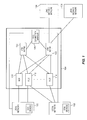
- FIG. 1 depicts an example of the invention. Those skilled in the art will appreciate numerous variations and permutations of the invention from FIG. 1 . Shown on FIG. 1 are: local network 100 , local network 102 , communications system 104 , long distance network 106 , and long distance network 108 . Local network 102 , local network 104 , long distance network 106 , and long distance network 108 are well known in the art. Communications system 104 interconnects these local and long distance networks as described in detail below.
- the local networks represent any communications device that desires connections, including connections to an ATM system. As such, communications devices are depicted within the local networks, although the communication devices could be anywhere.
- the long distance network represents any ATM system.
- Communications system 104 comprises: ATM interworking multiplexer (mux) 110 , mux 112 , mux 114 , ATM matrix 120 , ATM matrix 122 , and call/connection manager (CCM) 130 . As indicated on FIG. 1, additional muxes could be shown, but have been omitted for reasons of clarity.
- Local network 100 is connected to muxes 110 and 112 with conventional TDM connections, such as DS 3 , DS 2 , DS 1 , or DS 0 .
- Local network 102 is connected to mux 112 and mux 114 in a similar fashion. Both local network 100 and local network 102 are connected to CCM 130 with control links—typically Signaling System # 7 (SS 7 ) links. Muxes 110 , 112 , and 114 are each connected to ATM matrix 120 and to ATM matrix 122 with ATM virtual connections. CCM 130 is connected to both ATM matrix 120 and ATM matrix ATM 122 with ATM virtual connections. ATM matrix 122 is connected to long distance network 106 and to long distance network 108 :with ATM virtual connections. Typically, ATM virtual connections are designated by a Virtual Path Identification/Virtual Channel Identification (VPI/VCI).
- VPN/VCI Virtual Path Identification/Virtual Channel Identification
- CCM 130 exchanges signaling with the local and long distance networks and exerts control over communications system 104 .
- CCM 130 exchanges signaling with the local networks over the control links discussed above.
- CCM 130 exchanges signaling with the long distance networks using control links to the long distance networks that are established within the ATM virtual connections through ATM matrix 122 .
- CCM 130 exerts control over the muxes using control links to the muxes that are established within the ATM virtual connections through ATM matrix 120 and ATM matrix 122 .
- STPs Signal Transfer Points
- SCPs Service Control through ATM matrix 120 and Service. Control Points
- Interworking provides a conversion between different formats, such as TDM and ATM.
- the muxes are each able to interwork between TDM and ATM traffic on a per call basis in response to control instructions from the CCM. Typically, this requires breaking down the local network traffic to the DS 0 level.
- the mux also accepts a control instruction from CCM 130 assigning a particular DS 0 to a particular ATM virtual connection for a call. During that call, mux 110 . will interwork the assigned DS 0 with the assigned virtual connection.
- the muxes are each able to automatically interwork. between TDM and ATM traffic on a per call basis.
- the term “automatically” refers to a mux being pre-provisioned to interwork the particular connections. As will be discussed in detail below, the mux can also apply echo cancellation to selected calls.
- ATM matrix 120 provides ATM interconnections among the muxes, and also between the muxes and CCM 130 .
- ATM matrix 122 provides ATM interconnections between the muxes and the long distance networks, and also between CCM 130 and the long distance networks.
- ATM matrix 120 and ATM matrix 122 could be combined into a single ATM matrix.
- ATM matrix 122 and ATM matrix could be ATM cross-connects or ATM switches which are both well known in the art.
- CCM 130 exchanges signaling with the local and long distance networks and provides control instructions to the muxes.
- CCM 130 would accept the signaling from the particular network.
- CCM 130 would process the signaling and select connection assignments for the call.
- CCM 130 would provide the assignments as a control instruction to the appropriate mux.
- CCM 130 will cause the mux to apply echo cancellation on calls that use a long distance network.
- a communications device in local network 100 would seize a DS 0 port on mux 110 and send an SS 7 Initial Address Message (IAM) to CCM 130 .
- CCM 130 will process the IAM and identify local network 102 as the destination. This could be done by analyzing the called number.
- CCM 130 would select an ATM virtual connection from mux 110 through ATM matrix 120 to mux 114 .
- CCM 130 would provide a control instruction to mux 110 identifying the incoming DS 0 from local network 100 and the selected ATM virtual connection through ATM matrix 120 to mux 114 .
- CCM 130 would also select a DS 0 connection from mux 114 to a communications device in local network 102 .
- CCM 130 would provide a control instruction to mux 114 identifying the selected ATM virtual connection from mux 110 the outbound DS 0 to the communications device in local network 102 .
- Mux 110 would interwork the DS 0 from local network 100 with the ATM virtual connection through ATM matrix 120 to mux 114 .
- Mux 114 would interwork the ATM virtual connection from mux 110 through ATM matrix 120 with the DS 0 to the communications device in local network 102 .
- CCM 130 would also exchange signaling with both local networks during call set-up.
- a call connection is set up from local network 100 through mux 110 , ATM matrix 120 , and mux 114 to local network 102 .
- mux 112 could have been used in the alternative to ingress or egress the call or that the same mux could both ingress and egress a call.
- a communications device in local network 100 would seize a DS 0 port on mux 110 and send an SS 7 IAM to CCM 130 .
- CCM 130 will process the IAM and identify long distance network 106 as the destination. This could be done by analyzing the called number.
- CCM 130 would select an ATM virtual connection that will cause echo cancellation to be applied within mux 110 .
- CCM 130 will also select an ATM virtual connection from mux 110 through ATM matrix 122 to long distance network 106 .
- CCM 130 would provide a control instruction to mux 110 identifying the incoming DS 0 from local network 100 , the selected ATM virtual connection for echo cancellation, the DS 0 from echo cancellation, and the selected ATM virtual connection through ATM matrix 122 to long distance network 106 .
- Mux 110 would interwork the DS 0 from local network 100 with the ATM virtual connection for echo cancellation.
- Mux 110 would automatically interwork this ATM virtual connection with a DS 0 for echo cancellation.
- Mux 110 would then interwork the DS 0 from the echo cancellation with the ATM virtual connection through ATM matrix 122 to long distance network 106 .
- CCM 130 would also exchange signaling with local network 100 and long distance network 106 during call set-up. As a result, a call connection is set up from local network 100 through mux 110 and ATM matrix 122 to long distance network 106 .
- mux 112 could have been used in the alternative to ingress the call.
- Short distance network 106 would seize an ATM virtual connection through ATM matrix 122 to mux 110 and send a call set-up message through ATM matrix 122 to CCM 130 .
- CCM 130 will process the set-up message and identify local network 100 as the destination. This could be done by analyzing the called number.
- CCM 130 would select a DS 0 connection that will cause echo cancellation to be applied within mux 110 and a DS 0 connection to local network 100 .
- CCM 130 would provide a control instruction to mux 110 identifying the ATM virtual connection from long distance network 108 through ATM matrix 122 , the selected DS 0 for echo cancellation, the ATM virtual connection from echo cancellation, and the selected outbound DS 0 to local network 100 .
- Mux 110 would interwork the ATM virtual connection from long distance network 108 with the DS 0 for echo cancellation.
- Mux 110 would automatically interwork the DS 0 from echo cancellation with an ATM virtual connection.
- Mux 110 would interwork the ATM virtual connection from echo cancellation with the selected DS 0 to a communications device in local network 100 .
- CCM 130 would also exchange signaling with local network 100 and long distance network 108 during call set-up. As a result, a call connection is set up from long distance network 108 through ATM matrix 122 and mux 110 to local network 100 .
- mux 112 could have been used in the alternative to egress the call.
- CCM 130 routes calls through the muxes and ATM matrix 120 for local calls.
- CCM 130 routes calls through echo cancellation and ATM matrix 122 for long distance calls.
- Communications system 106 could be deployed as a part of one of the local networks or as a part of one of the long distance networks. It could also be deployed in a stand-alone fashion.
- FIG. 2 depicts another example of the invention with the mux shown in greater detail with other elements omitted for purposes of clarity.
- Reference numbers on FIG. 2 correspond to similar devices from FIG. 1 .
- Shown on FIG. 2 are: local network 200 , communications system 204 , and long distance network 206 .
- Communications system 204 is comprised of mux 210 , ATM matrix 220 , ATM matrix 222 , and CCM 230 . These elements are interconnected and operate in accord with the corresponding elements of FIG. 1 .
- Mux 210 is comprised of Interworking Unit (IWU) 250 , IWU 252 , and echo canceller 254 .
- IWU 250 is externally connected to local network 200 and ATM matrix 220 .
- IWU Interworking Unit
- IWU 250 is internally connected to IWU 252 with an ATM virtual connection.
- IWU 252 is externally connected to ATM matrix 222 .
- IWU 252 is internally connected to echo canceller 254 with DS 0 , E 0 , or connections that contain DS 0 s or E 0 s.
- the IWUs interwork between DS 0 connections and ATM virtual connections in response to control instructions from CCM 230 .
- Echo canceller 254 removes echo from telecommunications traffic.
- Local network 200 would seize a DS 0 port on IWU 250 of mux 210 and send an IAM to CCM 230 .
- CCM 230 will process the IAM and identify the local network 200 as the destination. This could be done by analyzing the called number.
- CCM 230 would select an ATM virtual connection from IWU 250 through ATM matrix 220 and back to IWU 250 , and select a DS 0 from IWU 250 back to local network 200 .
- CCM 230 would provide a control instruction to IWU 250 identifying the incoming DS 0 from local network 200 , the selected ATM virtual connection through ATM matrix 220 and back to IWU 250 , and the DS 0 from IWU 250 back to local network 200 .
- IWU 250 would interwork the DS 0 from local network 200 with the ATM virtual connection to ATM matrix 220 .
- IWU 250 would then interwork the ATM virtual connection back from ATM matrix 220 with the DS 0 back to local network 200 .
- CCM 230 will process the IAM and identify long distance network 206 as the destination. This could be done by analyzing the called number.
- CCM 230 would select an ATM virtual connection from IWU 250 to IWU 252 that will be automatically interworked by IWU 252 with a DS 0 to echo canceller 254 .
- CCM 130 will also select an ATM virtual connection from IWU 252 through ATM matrix 222 to long distance network 206 .
- CCM 230 would provide a control instruction to IWU 250 identifying the incoming DS 0 from local network 900 and the selected ATM virtual connection to IWU 252 for echo cancellation.
- CCM 230 would also provide a control instruction to IWU 252 identifying the DS 0 from echo canceller 254 and the selected ATM virtual connection through ATM matrix 222 to long distance network 206 .
- IWU 250 would interwork the DS 0 from local network 200 with the selected ATM virtual connection to IWU 252 .
- IWU 252 would automatically interwork the selected ATM virtual connection from IWU 250 with a DS 0 to echo canceller 254 .
- Echo canceller 254 would remove the echo from the half of the call from local network 200 and return the DS 0 to IWU 252 .
- IWU 252 would then interwork the DS 0 from echo canceller 254 with the selected ATM virtual connection through ATM matrix 222 to long distance network 206 .
- CCM 230 would also exchange signaling with local network 200 and long distance network 206 during call set-up. As a result, a call connection is set up from local network 200 through IWU 250 , IWU 252 , echo canceller 254 , and ATM matrix 222 to long distance network 206 .
- Short distance network 206 would seize an ATM virtual connection through ATM matrix 222 to IWU 252 and send a call set-up message through ATM matrix 222 to CCM 230 .
- CCM 230 will process the set-up message and identify local network 200 as the destination. This could be done by analyzing the called number.
- CCM 230 would select a DS 0 from IWU 252 to echo canceller 254 . After echo cancellation, this DS 0 would automatically be interworked by IWU 252 with an ATM virtual connection to IWU 250 .
- CCM 230 would also select a DS 0 connection from IWU 250 to local network 200 .
- CCM 230 would provide a control instruction to IWU 252 identifying the ATM virtual connection from long distance network 206 through ATM matrix 222 and the selected DS 0 to echo canceller 254 .
- CCM 230 would provide a control instruction to IWU 250 identifying the ATM virtual connection from IWU 252 and the selected outbound DS 0 to local network 200 .
- IWU 252 would interwork the ATM virtual connection from long distance network 206 with the DS 0 to echo canceller 254 .
- Echo canceller 254 would remove the echo from the half of the call from local network 200 and return the DS 0 to IWU 252 .
- IWU 252 would automatically interwork the DS 0 from echo canceller 254 with the ATM virtual connection to IWU 250
- IWU 250 would interwork the ATM virtual connection from IWU 252 with the selected DS 0 to local network 200 .
- CCM 230 would also exchange signaling with local network 200 and long distance network 206 during call set-up. As a result, a call connection is set up from long distance network 206 through ATM matrix 222 , IWU 252 , echo canceller 254 , and IWU 250 to local network 200 .
- CCM 230 routes local calls from IWU 250 to ATM matrix 220 for delivery to another mux and local network. For long distance calls that require echo cancellation, CCM 230 routes these calls through IWU 250 , IWU 252 , and echo canceller 254 , and ATM matrix 222 . Echo canceller 254 is depicted as internal to the mux, but it could also be externally located and connected by appropriate connections.
- FIG. 3 shows one embodiment of the mux that is suitable for the present invention, but other muxes that support the requirements of the invention are also applicable. Reference numbers on FIG. 3 correspond to similar devices from FIGS. 1 and 2. Shown on FIG. 3 are local network 300 , communications system 304 , and long distance network 306 . Communications system 304 includes mux 310 , ATM matrix 320 , ATM matrix 322 , and CCM 320 . Mux 310 includes IWU 350 , IWU 352 , and echo canceller 354 . The elements listed above are-interconnected and operate in accord with the corresponding elements of FIGS. 1 and 2.
- IWU 350 comprises: control interface 360 , OC-3 interface 362 , DS 3 interface 364 , DS 1 interface 366 , DS 0 interface 368 , ATM adaption Layer (AAL) 370 , and OC-3 interface 372 .
- OC-3 interface 362 accepts the OC-3 format and makes the conversion to DS 3 .
- DS 3 interface 364 accepts the DS 3 format and makes the conversion to DS 1 .
- DS 3 interface 364 can accept DS 3 s from OC-3 interface 362 or from an external connection.
- DS 1 interface 366 accepts the DS 1 format and makes the conversion to DS 0 .
- DS 1 interface 366 can accept DS 1 s from DS 3 interface 364 or from an external connection.
- DS 0 interface 368 accepts the DS 0 format and provides an interface to AAL 370 .
- OC-3 interface 372 is operational to exchange ATM cells with AAL 370 and ATM matrix 320 . It also provides a control link to control interface 360 .
- Control interface 360 accepts messages from CCM 330 over an ATM virtual connection through ATM matrix 320 and OC-3 interface 372 .
- Control interface 360 provides DS 0 /virtual connection assignments to AAL 370 for implementation.
- AAL 370 interworks DS 0 s with virtual connections in response to control interface 360 .
- IWU 352 comprises: control interface 74 , DS 1 interface 376 , DS 0 interface 378 , AAL 380 , and OC-3 interface 382 .
- DS 1 interface 376 accepts the DS 1 format and makes the conversion to DS 0 .
- DS 1 interface 376 can accept DS 1 s from echo canceller 354 .
- DS 0 interface 378 accepts the DS 0 format and provides an interface to AAL 380 .
- OC-3 interface 382 is operational to exchange ATM cells with AAL 380 and ATM matrix 322 . It also provides a control link to control interface 374 .
- Control interface 374 accepts messages from CCM 330 over an ATM virtual connection through ATM matrix 322 and OC-3 interface 382 .
- Control interface 374 provides DS 0 /virtual connection assignments to AAL 380 for implementation.
- AAL 380 interworks DS 0 s with virtual connections in response to control interface 360 .
- AAL 380 is pre-provisioned to automatically interwork a DS 0 with an ATM virtual connection without requiring a control instruction.
- An AAL comprises both a convergence sublayer and a segmentation and reassembly (SAR) layer.
- the AAL obtains the identity of the DS 0 and the ATM VPI/VCI from the control interface.
- the AAL is operational to convert between the DS 0 format and the ATM format, either automatically, or in response to control instructions. Acknowledgments that the assignments have been implemented may be sent back to the CCM if desired.
- AALs are known in the art and information about AALs is provided by International Telecommunications Union (ITU) document I. 363 .
- ITU International Telecommunications Union
- An AAL for voice is also described in U.S. Pat. No. 5,606,553 entitled “Cell Processing for Voice Transmission”, and hereby incorporated by reference into this application.
- VPI/VCIs A technique for processing VPI/VCIs is disclosed in patent application Ser. No. 08/633,832, filed on May 28, 1996, entitled “Telecommunications System with a Connection Processing System,” and hereby incorporated by reference into this application.
- DS 0 connections are bidirectional and ATM connections are typically unidirectional.
- two virtual connections in opposing directions will typically be required for each DS 0 .
- this can be accomplished provisioning the cross-connects with companion VPI/VCIs in the opposite direction as the original VPI/VCIs.
- the signaling processor is referred to as a call/connection manager (CCM), and it receives and processes telecommunications call signaling and control messages to select connections that establish communication paths for calls.
- CCM processes SS 7 signaling to select connections for a call.
- CCM processing is described in a U.S. patent application Ser. No. 08/754,349, filed on Nov. 22, 1996, which is entitled “Telecommunication System”, and which is incorporated herein by reference.
- the CCM performs many other functions in the context of call processing. It not only can control routing and select the actual connections, but it can also validate callers, control echo cancellers, generate billing information, invoke intelligent network functions, access remote databases, manage traffic, and balance network loads.
- the CCM described below can be adapted to operate in the above embodiments.
- FIG. 4 depicts a version of the CCM. Other versions are also contemplated.
- CCM 400 controls an ATM interworking multiplexer (mux) that performs interworking of DS 0 s and VPI/VCIs.
- the CCM may control other communications devices and connections in other embodiments.
- CCM 400 comprises signaling platform 410 , control platform 420 , and application platform 430 .
- Each of the platforms 410 , 420 , and 430 is coupled to the other platforms.
- Signaling platform 410 is externally coupled to the SS 7 systems—in particular to systems having a message transfer part (MTP), an ISDN user part (ISUP), a signaling connection control part (SCCP), an intelligent network application part (INAP), and a transaction capabilities application part (TCAP).
- Control platform 420 is externally coupled to a mux control, an echo control, a resource control, billing, and operations.
- Signaling platform 410 comprises MTP levels 1 - 3 , ISUP, TCAP, SCCP, and INAP functionality and is operational. to transmit and receive the SS 7 messages.
- the ISUP, SCCP, INAP, and TCAP functionality use MTP to transmit and receive the SS 7 messages. Together, this functionality is referred as an “SS 7 stack,” and it is well known.
- the software required by one skilled in the art to configure an SS 7 stack is commercially available, for example, from the Trillium company.
- Control platform 420 is comprised of various external interfaces including a mux interface, an echo interface, a resource control interface, a billing interface, and an operations interface.
- the mux interface exchanges messages with at least one mux. These messages comprise DS 0 to VPI/VCI assignments, acknowledgments, and status information.
- the echo control interface exchanges messages with echo control systems. Messages exchanged with echo control systems might acknowledgments and status information.
- the resource control interface exchanges messages with external resources.
- resources are devices that implement. continuity testing, encryption, compression, tone detection/transmission, voice detection, and voice messaging.
- the messages exchanged with resources are instructions to apply the resource to particular DS 0 s, acknowledgments, and status information. For example, a message may instruct a continuity testing resource to provide a loopback or to send and detect a tone for a continuity test.
- the billing interface transfers pertinent billing information to a billing system. Typical billing information includes the parties to the call, time points for the call, and any special features applied to the call.
- the operations interface allows for the configuration and control of CCM 400 .
- One skilled in the art will appreciate how to produce the software for the interfaces in control platform 420 .
- Application platform 430 is functional to process signaling information from signaling platform 410 in order to select connections. The identity of the selected connections are provided to control platform 420 for the mux interface. Application platform 430 is responsible for validation, translation, routing, call control, exceptions, screening, and error handling. In addition to providing the control requirements for the mux application platform 430 also provides requirements for echo control and resource control to the appropriate interface of control platform 420 . In addition, application platform 430 generates signaling information for transmission by signaling platform 410 . The signaling information might be ISUP, INAP, or TCAP messages to external network elements. Pertinent information for each call is stored in a call control block (CCB) for the call. The CCB can be used for tracking and billing the call.
- CCB call control block
- Application platform 430 operates in general accord with the Basic Call Model (BCM) defined by the ITU. An instance of the BCM is created to handle each call.
- the BCM includes an originating process and a terminating process.
- Application platform 430 includes a service switching function (SSF) that is used to invoke the service control function (SCF).
- SSF service switching function
- SCF service control function
- SCP service control point
- SCF service control point
- the SCF is, queried with TCAP or INAP messages.
- the originating or terminating processes will access remote databases with intelligent network (IN) functionality via the SSF function.
- Software requirements for application platform 430 can be produced in specification and description language (SDL) defined in ITU-T Z.100.
- SDL specification and description language
- the SDL can be converted into C code. Additional C and C++ code can be added as required to establish the environment.
- CCM 400 can be comprised of the above-described software loaded onto a computer.
- the computer can be an Integrated Micro Products (IMP) FT-Sparc 600 using the Solaris operating system and conventional-database systems. It may be desirable. to utilize the multi-threading capability of a Unix operating system.
- IMP Integrated Micro Products
- application platform 430 processes signaling information to control numerous systems and facilitate call connections and services.
- the SS 7 signaling is exchanged with external components through signaling platform 410
- control information is exchanged with external systems through control platform 420 .
- CCM 400 is not integrated into a switch CPU that is coupled to a switching matrix. Unlike an SCP, CCM 400 is capable of processing ISUP messages independently of TCAP queries.
- Call processing typically entails two aspects.
- First, an incoming or “originating” connection is recognized by an originating call process. For example, the initial connection that a call uses to enter a network is the originating connection in that network.
- Second, an outgoing or “terminating” connection is selected by a terminating call process. For example, the terminating connection is coupled to the originating connection in order to extend the call through the network.
- These two aspects of call processing are referred to as the originating side of the call and the terminating side of the call.
- FIG. 5 depicts a data structure used by application platform 430 of FIG. 4 to execute the basic call model. This is accomplished through a series of tables that point to one another in various ways.
- the pointers are typically comprised of next function and next index designations.
- the next function points to the next table, and the next index points to an entry or a range of entries in that table.
- the data structure has trunk circuit table 500 , trunk group table 502 , exception table 504 , ANI table 506 , called number table 508 , and routing table 510 .
- Trunk circuit table 500 contains information related to the connections. Typically, the connections are DS 0 or ATM virtual connections. Initially, trunk circuit table 500 is used to retrieve information about the originating connection. Later, the table is used to retrieve information about the terminating connection. When the originating connection is being processed, the trunk group number in trunk circuit table 500 points to the applicable trunk group for the originating connection in trunk group table 502 .
- Trunk group table 502 contains information related to the originating and terminating trunk groups. When the originating connection is being processed, trunk group table 502 provides information relevant to the trunk group for the originating connection and typically points to exception table 504 .
- Exception table 504 is used to identify various exception conditions related to the call that may influence the routing or other handling of the call. Typically, exception table 504 points to ANI table 506 . Although, exception table 504 may point directly to trunk group table 502 , called number table 508 , or routing table 510 .
- ANI table 506 is used to identify any special characteristics related to the caller's number.
- the caller's number is commonly known as automatic number identification (ANI).
- ANI table 506 typically points to called number table 508 .
- ANI table 506 may point directly to trunk group table 502 or routing table 510 .
- Called number table 508 is used to identify routing requirements based on the called number. This will be the case for standard telephone calls. Called number table 508 typically points to routing table 510 . Although, it may point to trunk group table 502 .
- Routing table 510 has information relating to the routing of the call for the various connections. Routing table 510 is entered from a pointer in either exception table 504 , ANI table 506 , or called number table 508 . Routing table 510 typically points to a trunk group in trunk group table 502 .
- trunk group table 502 When exception table 504 , ANI table 506 , called number table 508 , or routing table 510 point to trunk group table 502 , they effectively select the terminating trunk group. When the terminating connection is being processed, the trunk group number in trunk group table 502 points to the trunk group that contains the applicable terminating connection in trunk circuit table 502 .
- the terminating trunk circuit is used to extend the call.
- the trunk circuit is typically a VPI/VCI or a DS 0 .
- FIG. 6 is an overlay of FIG. 5 .
- the tables from FIG. 5 are present, but for clarity, their pointers have been omitted, but their reference numbers have been retained.
- FIG. 6 illustrates additional tables that can be accessed from the tables of FIG. 5 . These include CCM ID table 600 , treatment table 604 , query/response table 606 , and message table 608 .
- CCM ID table 600 contains various CCM SS 7 point codes. It can be accessed from trunk group table 502 , and it points back to trunk group table 502 .
- Treatment table 604 identifies various special actions to be taken in the course of call processing. This will typically result in the transmission of a release message (REL) and a cause value. Treatment table 604 can be accessed from trunk circuit table 500 , trunk group table 502 , exception table 504 , ANI table 506 , called number table 508 , routing table 510 , and query/response table 606 .
- REL release message
- Query/response table 606 has information used to invoke the SCF. It can be accessed by trunk group table. 502 , exception table 504 , ANI table 506 , called number table 508 , and routing table 510 . It points to trunk group table 502 , exception table 504 , ANI table 506 , called number table 508 , routing table 510 , and treatment table 604 .
- Message table 608 is used to provide instructions for messages from the termination side of the call. It can be accessed by trunk group table 502 and points to trunk group table 502 .
- FIGS. 7-14 depict examples of the various tables described above.
- FIG. 7 depicts an example of the trunk circuit table. Initially, the trunk circuit table is used to access information about the originating circuit. Later in the processing, it is used to provide information about the terminating circuit. For originating circuit processing, the associated point code is used to enter the table. This is the point code of the switch or CCM associated with the originating circuit. For terminating circuit processing, the trunk group number is used to enter the table.
- the table also contains the circuit identification code (CIC).
- the CIC identifies the circuit which is typically a DS 0 or a VPI/VCI.
- the invention is capable of mapping the SS 7 CICs to the ATM VPI/VCI. If the circuit is ATM, the virtual path (VP) and the virtual channel. (VC) also can be used for identification.
- the group member number is a numeric code that is used for terminating circuit selection.
- the hardware identifier identifies the location of the hardware associated with the originating circuit.
- the echo canceller (EC) identification (ID) entry identifies the echo canceller for the originating circuit.
- the remaining fields are dynamic in that they are filled during call processing.
- the echo control entry is filled based on three fields in signaling messages: the echo suppresser indicator in the IAM or CRM, the echo control device indicator in the ACM or CPM, and the information transfer capability in the IAM. This information is used to determine if echo control is required on the call.
- the satellite indicator is filled with the satellite indicator in the IAM or CRM. It may be used to reject a call if too many satellites are used.
- the circuit status indicates if the given circuit is idle, blocked, or not blocked.
- the circuit state indicates the current state of the circuit, for example, active or transient.
- the time/date indicates when the idle circuit went idle.
- FIG. 8 depicts an example of the trunk group table.
- the trunk group number from the trunk circuit table is used to key into the trunk table.
- Glare resolution indicates how a glare situation is to be resolved. Glare is dual seizure of the same circuit. If the glare resolution entry is set to “even/odd,” the network element with the higher point code controls the even circuits, and the network element with the lower point code controls the odd circuits. If the glare resolution entry is set to “all,” the CCM controls all of the circuits. If the glare resolution entry is set to “none,” the CCM yields.
- the continuity control entry lists the percent of calls requiring continuity tests on the trunk group.
- the common language location identifier (CLLI) entry is a Bellcore standardized entry.
- the satellite trunk group entry indicates that the trunk group uses a satellite.
- the satellite trunk group entry is used in conjunction with the satellite indicator field described above to determine if the call has used too many satellite connections and, therefore, must be rejected.
- the service indicator indicates if the incoming message is from a CCM (ATM) or a switch (TDM).
- the outgoing message index (OMI) points to the message table so that outgoing messages can obtain parameters.
- the associated number plan area (NPA) entry identifies the area code.
- Selection sequence indicates the methodology that will be used to select a connection.
- the selection sequence field designations tell the trunk group to select circuits based on the following: least idle, most idle, ascending, descending, clockwise, and counterclockwise.
- the hop counter is decremented from the IAM. If the hop counter is zero, the call is released.
- Automatic congestion control (ACC) active indicates whether or not congestion control is active. If automatic congestion control is active, the CCM may release the call.
- ACC Automatic congestion control
- the CCM may release the call.
- the next function and index are used to enter the trunk circuit table.
- FIG. 9 depicts an example of the exception table.
- the index is used as a pointer to enter the table.
- the carrier selection identification (ID) parameter indicates how the caller reached the network and is used for routing certain types of calls. The following are used for this field: spare or no indication, selected carrier identification code presubscribed and input by the calling party, selected carrier identification code presubscribed and not input by the calling party, selected carrier identification code presubscribed and no indication of input by the calling party, and selected carrier identification code not presubscribed and input by the calling party.
- the carrier identification (ID) indicates the network that the caller wants to use. This is used to route calls directly to the desired network.
- the called party number nature of address differentiates between 0+ calls, 1+ calls, test calls, and international calls. For example, international calls might be routed to a pre-selected international carrier.
- the called party “digits from” and “digits to” focus further processing unique to a defined range of called numbers.
- the “digits from” field is a decimal number ranging from 1-15 digits. It can be any length and, if filled with less than 15 digits, is filled with 0s for the remaining digits.
- the “digits to” field is a decimal number ranging from 1-15 digits. It can be any length and if filled with less than 15 digits, is filled with 9s for the remaining digits.
- the next function and next index entries point to the next table which is typically the ANI table.
- FIG. 10 depicts an example of the ANI table.
- the index is used to enter the fields of the table.
- the calling party category differentiates among types of calling parties, for example, test calls, emergency calls, and ordinary calls.
- the calling party/charge number entry nature of address indicates how the ANI is to be obtained.
- the following is the table fill that is used in this field: unknown, unique subscriber numbers, ANI not available or not provided, unique national number, ANI of the called party included, ANI of the called party not included, ANI of the called party includes national number, non-unique subscriber number, non-unique national number, non-unique international number, test line test code, and all other parameter values.
- the “digits from” and “digits to” focus further processing unique to ANI within a given range.
- the data entry indicates if the ANI represents a data device that does not need echo control.
- Originating line information differentiates among ordinary subscriber, multiparty line, ANI failure, station level rating, special operator handling, automatic identified outward dialing, coin or non-coin call using database access, 800 / 888 service call, coin, prison/inmate service, intercept (blank, trouble, and regular), operator handled call, outward wide area telecommunications service, telecommunications relay service (TRS), cellular services, private paystation, and access for private virtual network types of service.
- the next function and next index point to the next table which is typically the called number table.
- FIG. 11 depicts an example of the called number table.
- the index is used to enter the table.
- the called number nature of address entry indicates the type of dialed number, for example, national versus international.
- the “digits from” and “digits to” entries focus further processing unique to a range of called numbers.
- the processing follows the processing logic of the “digits from” and “digits to” fields in FIG. 9 .
- the next function and next index point to the next table which is typically the routing table.
- FIG. 12 depicts an example of the routing table.
- the index is used to enter the table.
- the transit network selection (TNS) network identification (ID) plan indicates the number of digits to use for the CIC.
- the transit network selection “digits from” and “digits to” fields define the range of numbers to identify an international carrier.
- the circuit code indicates the need for an operator on the call.
- the next function and next index entries in the routing table are used to identify a trunk group.
- the second and third next function/index entries define alternate routes.
- the third next function entry can also point back to another set of next functions in the routing table in order to expand the number of alternate route choices.
- the only other entries allowed are pointers to the treatment table. If the routing table points to the trunk group table, then the trunk group table typically points to a trunk circuit in the trunk circuit table.
- the yield from the trunk circuit table is the terminating connection for the call.
- the tables can be configured and relate to one another in such a way that call processes can enter the trunk circuit table for the originating connection and can traverse through the tables by keying on information and using pointers.
- the yield of the tables is typically a terminating connection identified by the trunk circuit table.
- treatment is specified by the treatment table instead of a connection.
- a trunk group can be selected, processing may proceed directly to the trunk group table for terminating circuit selection. For example, it may be desirable to route calls from a particular ANI over a particular set of trunk groups. In this case, the ANI table would point directly to the trunk group table, and the trunk group table would point to the trunk circuit table for a terminating circuit.
- the default path through the tables is: trunk circuit, trunk group, exception, ANI, called number, routing, trunk group, and trunk circuit.
- FIG. 13 depicts. an example of the treatment table. Either the index or the message received cause number are filled and are used to enter the table. If the index is filled and used to enter the table, the general location, coding standard, and cause value indicator are used to generate an SS 7 REL. The message received cause value entry is the cause value in a received SS 7 message. If the message received cause value is filled and used to enter the table, then the cause value from that message is used in a REL from the CCM. The next function and next index point to the next table.
- FIG. 14 depicts an example of the message table.
- This table allows the CCM to alter information in outgoing messages.
- Message type is used to enter the table, and it represents the outgoing standard SS 7 message type.
- the parameter is the pertinent parameter within the outgoing SS 7 message.
- the indexes point to various entries in the trunk group table and determine if parameters can be unchanged, omitted, or modified in the outgoing messages.
Abstract
Description
| ACM | -- | Address Complete Message | ||
| ANM | -- | Answer Message | ||
| BLO | -- | Blocking | ||
| BLA | -- | Blocking Acknowledgment | ||
| CPG | -- | Call Progress | ||
| CRG | -- | Charge Information | ||
| CGB | -- | Circuit Group Blocking | ||
| CGBA | -- | Circuit Group Blocking Acknowledgment | ||
| GRS | -- | Circuit Group Reset | ||
| GRA | -- | Circuit Group Reset Acknowledgment | ||
| CGU | -- | Circuit Group Unblocking | ||
| CGUA | -- | Circuit Group Unblocking Acknowledgment | ||
| CQM | -- | Circuit Group Query | ||
| CQR | -- | Circuit Group Query Response | ||
| CRM | -- | Circuit Reservation Message | ||
| CRA | -- | Circuit Reservation Acknowledgment | ||
| CVT | -- | Circuit Validation Test | ||
| CVR | -- | Circuit Validation Response | ||
| CFN | -- | Confusion | ||
| COT | -- | Continuity | ||
| CCR | -- | Continuity Check Request | ||
| EXM | -- | Exit Message | ||
| INF | -- | Information | ||
| INR | -- | Information Request | ||
| IAM | -- | Initial Address | ||
| LPA | -- | Loop Back Acknowledgment | ||
| PAM | -- | Pass Along | ||
| REL | -- | Release | ||
| RLC | -- | Release Complete | ||
| RSC | -- | Reset Circuit | ||
| RES | -- | Resume | ||
| SUS | -- | Suspend | ||
| UBL | -- | Unblocking | ||
| UBA | -- | Unblocking Acknowledgment | ||
| UCIC | -- | Unequipped Circuit Identification Code. | ||
Claims (12)
Priority Applications (1)
| Application Number | Priority Date | Filing Date | Title |
|---|---|---|---|
| US09/546,785 US6674729B1 (en) | 1997-04-16 | 2000-04-11 | Communications system for providing ATM connections and echo cancellation |
Applications Claiming Priority (2)
| Application Number | Priority Date | Filing Date | Title |
|---|---|---|---|
| US08/840,317 US6067299A (en) | 1997-04-16 | 1997-04-16 | Communications system for providing ATM connections and echo cancellation |
| US09/546,785 US6674729B1 (en) | 1997-04-16 | 2000-04-11 | Communications system for providing ATM connections and echo cancellation |
Related Parent Applications (1)
| Application Number | Title | Priority Date | Filing Date |
|---|---|---|---|
| US08/840,317 Continuation US6067299A (en) | 1997-04-16 | 1997-04-16 | Communications system for providing ATM connections and echo cancellation |
Publications (1)
| Publication Number | Publication Date |
|---|---|
| US6674729B1 true US6674729B1 (en) | 2004-01-06 |
Family
ID=25282019
Family Applications (2)
| Application Number | Title | Priority Date | Filing Date |
|---|---|---|---|
| US08/840,317 Expired - Lifetime US6067299A (en) | 1997-04-16 | 1997-04-16 | Communications system for providing ATM connections and echo cancellation |
| US09/546,785 Expired - Lifetime US6674729B1 (en) | 1997-04-16 | 2000-04-11 | Communications system for providing ATM connections and echo cancellation |
Family Applications Before (1)
| Application Number | Title | Priority Date | Filing Date |
|---|---|---|---|
| US08/840,317 Expired - Lifetime US6067299A (en) | 1997-04-16 | 1997-04-16 | Communications system for providing ATM connections and echo cancellation |
Country Status (1)
| Country | Link |
|---|---|
| US (2) | US6067299A (en) |
Cited By (2)
| Publication number | Priority date | Publication date | Assignee | Title |
|---|---|---|---|---|
| US6980557B1 (en) * | 1998-11-03 | 2005-12-27 | Siemens Aktiengesellschaft | Communications system with communication terminals which are connected to a switching system via a packet-oriented communication network |
| US6982950B1 (en) * | 1998-12-22 | 2006-01-03 | Sprint Communications Company L.P. | System and method for connecting a call in a tandem architecture |
Families Citing this family (28)
| Publication number | Priority date | Publication date | Assignee | Title |
|---|---|---|---|---|
| US5991301A (en) | 1994-05-05 | 1999-11-23 | Sprint Communications Co. L.P. | Broadband telecommunications system |
| US6067299A (en) * | 1997-04-16 | 2000-05-23 | Sprint Communications Company, L.P. | Communications system for providing ATM connections and echo cancellation |
| US6172973B1 (en) * | 1997-09-17 | 2001-01-09 | Nortel Networks Limited | Apparatus and method for reducing delay for voice over ATM using co-located switches |
| IES80915B2 (en) * | 1997-12-15 | 1999-06-30 | Tellabs Research Limited | Telecommunication systems |
| US6483837B1 (en) * | 1998-02-20 | 2002-11-19 | Sprint Communications Company L.P. | System and method for connecting a call with an interworking system |
| US6546022B1 (en) * | 1998-04-03 | 2003-04-08 | Sprint Communications Company, L.P. | Method, system and apparatus for processing information in a telecommunications system |
| US6496512B1 (en) * | 1998-12-22 | 2002-12-17 | Sprint Communications Company L.P. | System and method for connecting calls with a time division multiplex matrix |
| US6882652B1 (en) | 1999-08-06 | 2005-04-19 | Tellabs Operations, Inc. | Private lines traversing a packet network and re-arrangement of channels among packet network connections |
| US7054273B1 (en) * | 1999-08-06 | 2006-05-30 | Tellabs Operations, Inc. | Circuit integrity in a packet-switched network |
| US7180869B2 (en) | 2001-08-30 | 2007-02-20 | Avaya Technology Corp. | Comprehensive echo control system |
| US7095720B1 (en) | 2001-10-17 | 2006-08-22 | Sprint Communications Company L.P. | Trunk level echo canceller test system |
| US8949381B1 (en) * | 2003-12-31 | 2015-02-03 | Brixham Solutions Ltd. | Network service provisioning |
| US7697667B1 (en) | 2005-09-23 | 2010-04-13 | Sprint Communications Company L.P. | Voicemail recall feature |
| US9217998B2 (en) * | 2006-09-29 | 2015-12-22 | Rockwell Automation Technologies, Inc. | Management and development of an industrial environment |
| US7912560B2 (en) * | 2006-09-29 | 2011-03-22 | Rockwell Automation Technologies, Inc. | Module and controller operation for industrial control systems |
| US8732658B2 (en) * | 2006-09-29 | 2014-05-20 | Rockwell Automation Technologies, Inc. | Layered interface in an industrial environment |
| US8265775B2 (en) * | 2008-09-30 | 2012-09-11 | Rockwell Automation Technologies, Inc. | Modular object publication and discovery |
| US7676279B2 (en) * | 2006-09-29 | 2010-03-09 | Rockwell Automation Technologies, Inc. | Services for industrial control systems |
| US7856279B2 (en) * | 2006-09-29 | 2010-12-21 | Rockwell Automation Technologies, Inc. | Module structure and use for industrial control systems |
| US7835805B2 (en) * | 2006-09-29 | 2010-11-16 | Rockwell Automation Technologies, Inc. | HMI views of modules for industrial control systems |
| US9261877B2 (en) * | 2006-09-29 | 2016-02-16 | Rockwell Automation Technologies, Inc. | Multiple machine interface |
| US8078296B2 (en) * | 2006-09-29 | 2011-12-13 | Rockwell Automation Technologies, Inc. | Dynamic procedure selection |
| US8776092B2 (en) | 2006-09-29 | 2014-07-08 | Rockwell Automation Technologies, Inc. | Multiple interface support |
| US8041435B2 (en) * | 2008-09-30 | 2011-10-18 | Rockwell Automation Technologies, Inc. | Modular object dynamic hosting |
| US20080082577A1 (en) * | 2006-09-29 | 2008-04-03 | Rockwell Automation Technologies, Inc. | Module classification and searching for industrial control systems |
| US9058032B2 (en) * | 2006-09-29 | 2015-06-16 | Rockwell Automation Technologies, Inc. | Hosting requirements for services |
| US8818757B2 (en) * | 2008-09-30 | 2014-08-26 | Rockwell Automation Technologies, Inc. | Modular object and host matching |
| US10115092B1 (en) * | 2016-03-04 | 2018-10-30 | Sprint Communications Company L.P. | Service composition in a mobile communication device application framework |
Citations (40)
| Publication number | Priority date | Publication date | Assignee | Title |
|---|---|---|---|---|
| US4720850A (en) | 1986-03-14 | 1988-01-19 | American Telephone And Telegraph Company At&T Bell Laboratories | Communication system control arrangement |
| US4763317A (en) | 1985-12-13 | 1988-08-09 | American Telephone And Telegraph Company, At&T Bell Laboratories | Digital communication network architecture for providing universal information services |
| US5051983A (en) | 1988-09-23 | 1991-09-24 | Siemens Aktiengesellschaft | Method and circuitry for transmission of speech signals in a broad-band communications network |
| US5115427A (en) | 1990-03-30 | 1992-05-19 | At&T Bell Laboratories | Arrangements for switching multiple packet types combined in a single packet stream |
| US5182550A (en) | 1985-05-31 | 1993-01-26 | Fujitsu Limited | Inter-network connection system |
| US5204857A (en) | 1990-08-20 | 1993-04-20 | Kabushiki Kaisha Toshiba | ATM exchange system |
| US5289536A (en) | 1991-03-20 | 1994-02-22 | Nec Corporation | Least cost routing method according to information transfer capability of customer premises equipment |
| US5327421A (en) | 1992-11-06 | 1994-07-05 | At&T Bell Laboratories | Apparatus for interfacing between telecommunications call signals and broadband signals |
| US5339318A (en) | 1991-10-24 | 1994-08-16 | Fujitsu Limited | VPI and VCI assignment system in ATM system |
| US5345445A (en) | 1992-11-06 | 1994-09-06 | At&T Bell Laboratories | Establishing telecommunications calls in a broadband network |
| US5434852A (en) | 1993-06-25 | 1995-07-18 | At&T Corp. | Distributed processing architechture for control of broadband and narrowband communications networks |
| US5459722A (en) | 1994-06-30 | 1995-10-17 | At&T Ipm Corp. | Asynchronous transfer mode (ATM) transport of voice-band signals |
| US5459721A (en) | 1993-06-18 | 1995-10-17 | Nec Corporation | Called equipment selection method in ISDN packet switching mode and packet switching system for digital network |
| US5469501A (en) | 1990-10-22 | 1995-11-21 | Canon Kabushiki Kaisha | Communication exchange apparatus with switching of communication terminal information |
| US5483527A (en) | 1994-12-21 | 1996-01-09 | At&T Corp. | Terminal adapter for interfacing an ATM network with a STM network |
| US5509010A (en) | 1993-06-25 | 1996-04-16 | At&T Corp. | Communications signaling protocols |
| US5513180A (en) | 1991-05-14 | 1996-04-30 | Fujitsu Limited | Television signal and ATM cell switching system |
| US5526359A (en) | 1993-12-30 | 1996-06-11 | Dsc Communications Corporation | Integrated multi-fabric digital cross-connect timing architecture |
| US5530724A (en) | 1994-11-29 | 1996-06-25 | At&T Corp. | Echo canceler with automatic enablement/disablement on a per-call basis |
| US5541917A (en) | 1994-09-12 | 1996-07-30 | Bell Atlantic | Video and TELCO network control functionality |
| US5568475A (en) | 1994-12-21 | 1996-10-22 | Lucent Technologies Inc. | ATM network architecture employing an out-of-band signaling network |
| US5583849A (en) | 1993-09-27 | 1996-12-10 | Siemens Aktiengesellschaft | Method and circuit arrangement for transmitting message cells via virtual paths of an ATM communication system |
| US5623491A (en) | 1995-03-21 | 1997-04-22 | Dsc Communications Corporation | Device for adapting narrowband voice traffic of a local access network to allow transmission over a broadband asynchronous transfer mode network |
| US5684792A (en) | 1994-10-20 | 1997-11-04 | Fujitsu Limited | Echo canceller system in an ATM network |
| US5765108A (en) | 1991-07-31 | 1998-06-09 | Telstra Corporation Limited | Telecommunications system |
| US5784371A (en) | 1995-01-13 | 1998-07-21 | Nec Corporation | ATM electronic exchange network system and electrode exchange equipment for use in the same |
| US5825780A (en) | 1994-05-05 | 1998-10-20 | Sprint Communications Co.L.P. | Method, system and apparatus for telecommunications control |
| US5867562A (en) | 1996-04-17 | 1999-02-02 | Scherer; Gordon F. | Call processing system with call screening |
| US5889773A (en) | 1996-11-27 | 1999-03-30 | Alcatel Usa Sourcing, L.P. | Method and apparatus for placing time division multiplexed telephony traffic into an asynchronous transfer mode format |
| US5917815A (en) | 1995-12-29 | 1999-06-29 | Lucent Technologies Inc. | Method and apparatus for converting synchronous narrowband signals into a SONET virtual tributary group for combining with broadband asynchronous transfer mode signals in an integrated telecommunications network |
| US5920562A (en) | 1996-11-22 | 1999-07-06 | Sprint Communications Co. L.P. | Systems and methods for providing enhanced services for telecommunication call |
| US5991301A (en) | 1994-05-05 | 1999-11-23 | Sprint Communications Co. L.P. | Broadband telecommunications system |
| US6023474A (en) | 1996-11-22 | 2000-02-08 | Sprint Communications C.O.L.P. | Broadband telecommunications system interface |
| US6026086A (en) | 1997-01-08 | 2000-02-15 | Motorola, Inc. | Apparatus, system and method for a unified circuit switched and packet-based communications system architecture with network interworking functionality |
| US6041043A (en) | 1996-10-25 | 2000-03-21 | Tektronix, Inc. | SONET path/ATM physical layer transmit/receive processor |
| US6067299A (en) * | 1997-04-16 | 2000-05-23 | Sprint Communications Company, L.P. | Communications system for providing ATM connections and echo cancellation |
| US6181703B1 (en) | 1995-09-08 | 2001-01-30 | Sprint Communications Company L. P. | System for managing telecommunications |
| US6324179B1 (en) | 1994-12-21 | 2001-11-27 | Lucent Technologies Inc. | ATM network arranged to interface with STM in-band signaling |
| US6411624B1 (en) * | 1994-05-05 | 2002-06-25 | Sprint Communications Company L.P. | Telecommunications system |
| US6487200B1 (en) * | 1996-04-04 | 2002-11-26 | At&T Corp. | Packet telephone system |
Family Cites Families (138)
| Publication number | Priority date | Publication date | Assignee | Title |
|---|---|---|---|---|
| US4201889A (en) * | 1978-03-17 | 1980-05-06 | International Telephone And Telegraph | Distributed control digital switching system |
| US4310727A (en) * | 1980-02-04 | 1982-01-12 | Bell Telephone Laboratories, Incorporated | Method of processing special service telephone calls |
| US4348554A (en) * | 1980-03-21 | 1982-09-07 | Bell Telephone Laboratories, Incorporated | Method of providing virtual private network telephone service |
| JPS57159192A (en) * | 1981-03-27 | 1982-10-01 | Hitachi Ltd | Audio packet exchange system |
| US4565903A (en) * | 1983-08-03 | 1986-01-21 | At&T Bell Laboratories | Telephone interexchange carrier selection |
| US4554659A (en) * | 1983-12-12 | 1985-11-19 | At&T Bell Laboratories | Data communication network |
| US4683563A (en) * | 1984-10-11 | 1987-07-28 | American Telephone And Telegraph Company, At&T Bell Laboratories | Data communication network |
| US4730312A (en) * | 1986-02-21 | 1988-03-08 | San/Bar Corporation | Voice, data or both over one telephone line in a T-1 carrier system |
| US4736364A (en) * | 1986-03-12 | 1988-04-05 | American Telephone And Telegraph Company, At&T Bell Laboratories | Switching system control arrangements |
| US4748658A (en) * | 1986-07-16 | 1988-05-31 | Bell Communications Research, Inc. | Architecture for allocating resources in a telecommunications network |
| BE1000512A7 (en) * | 1987-05-07 | 1989-01-10 | Bell Telephone Mfg | Switching network. |
| US4823338B1 (en) * | 1987-08-03 | 1998-11-10 | At & T Information Systems Inc | Virtual local area network |
| DE3742939A1 (en) * | 1987-12-18 | 1989-07-06 | Standard Elektrik Lorenz Ag | METHOD FOR HYBRID PACKING AND DEVICES THEREFOR |
| GB8802533D0 (en) * | 1988-02-04 | 1988-03-02 | Plessey Co Plc | Data packet switching |
| US4896319A (en) * | 1988-03-31 | 1990-01-23 | American Telephone And Telegraph Company, At&T Bell Laboratories | Identification and authentication of end user systems for packet communications network services |
| US4853955A (en) * | 1988-04-27 | 1989-08-01 | Network Access Corporation | Apparatus and method for providing existing telephone switching equipment with the capability of using the SS7 protocol |
| US5058104A (en) * | 1988-07-26 | 1991-10-15 | Nec Corporation | Tdm demultiplexer with dedicated maintenance channels to indicate high-speed line faults to low speed circuits |
| US5089954A (en) * | 1988-08-08 | 1992-02-18 | Bell Communications Research, Inc. | Method for handling conversational transactions in a distributed processing environment |
| US5101404A (en) * | 1988-08-26 | 1992-03-31 | Hitachi, Ltd. | Signalling apparatus for use in an ATM switching system |
| EP0437422B1 (en) * | 1988-09-30 | 1993-11-18 | Siemens Aktiengesellschaft | Communication system for forming virtual annular networks in a fast packet switching network |
| US5258752A (en) * | 1988-11-25 | 1993-11-02 | Sumitomo Electric Industries, Ltd. | Broad band digital exchange |
| US4991204A (en) * | 1988-12-05 | 1991-02-05 | Nippon Telegraph And Telephone Corporation | Adaptive routing control method |
| DE3912660C1 (en) * | 1989-04-18 | 1990-08-30 | Wandel & Goltermann Gmbh & Co, 7412 Eningen, De | |
| US5018191A (en) * | 1989-10-23 | 1991-05-21 | At&T Bell Laboratories | Special service call routing |
| US4993014A (en) * | 1989-05-30 | 1991-02-12 | At&T Bell Laboratories | Dynamic shared facility system for private networks |
| JP2964151B2 (en) * | 1989-07-03 | 1999-10-18 | 富士通株式会社 | Communication control method |
| DE4020775A1 (en) * | 1989-08-09 | 1991-02-14 | Standard Elektrik Lorenz Ag | COUPLING NETWORK AND COUPLING NETWORK MODULE FOR AN ATM SYSTEM |
| US5231631A (en) * | 1989-08-15 | 1993-07-27 | At&T Bell Laboratories | Arrangement for regulating traffic in a high speed data network |
| JPH03104451A (en) * | 1989-09-19 | 1991-05-01 | Fujitsu Ltd | Route changeover system for multi-stage link exchange system |
| US5434981A (en) * | 1989-09-28 | 1995-07-18 | Rockwell International Corporation | Functionally programmable PCM data analyzer and transmitter for use in telecommunication equipment |
| US5048081A (en) * | 1989-12-28 | 1991-09-10 | At&T Bell Laboratories | Arrangement for routing packetized messages |
| JPH03234137A (en) * | 1990-02-08 | 1991-10-18 | Fujitsu Ltd | Signaling cell switching method and signaling cell switching system |
| JP2957223B2 (en) * | 1990-03-20 | 1999-10-04 | 富士通株式会社 | Load distribution control method for call processor |
| CA2038646C (en) * | 1990-03-20 | 1995-02-07 | Katsumi Oomuro | Atm communication system with optimal traffic control by changing the allocated bandwidth |
| ATE127988T1 (en) * | 1990-03-23 | 1995-09-15 | Siemens Ag | METHOD FOR SETTING UP VIRTUAL CONNECTIONS IN EXCHANGE FACILITIES WORKING IN AN ASYNCHRONOUS TRANSFER MODE. |
| US5003584A (en) * | 1990-04-16 | 1991-03-26 | At&T Bell Laboratories | Method and apparatus for the billing of value-added communication calls |
| JP2555907B2 (en) * | 1990-05-23 | 1996-11-20 | 日本電気株式会社 | Complex network address routing control system |
| US5231633A (en) * | 1990-07-11 | 1993-07-27 | Codex Corporation | Method for prioritizing, selectively discarding, and multiplexing differing traffic type fast packets |
| DE69130271T2 (en) * | 1990-07-26 | 1999-06-02 | Nec Corp | Routing system suitable for the effective processing of routing information |
| JPH04100342A (en) * | 1990-08-20 | 1992-04-02 | Toshiba Corp | Traffic control system |
| US5115431A (en) * | 1990-09-28 | 1992-05-19 | Stratacom, Inc. | Method and apparatus for packet communications signaling |
| US5193110A (en) * | 1990-10-09 | 1993-03-09 | Boston Technology, Incorporated | Integrated services platform for telephone communication system |
| US5453981A (en) * | 1990-10-16 | 1995-09-26 | Kabushiki Kaisha Toshiba | Method of controlling communication network incorporating virtual channels exchange nodes and virtual paths exchange nodes |
| DE69131089T2 (en) * | 1990-10-20 | 1999-08-26 | Fujitsu Ltd | ATM switching unit |
| JP3001953B2 (en) * | 1990-10-20 | 2000-01-24 | 富士通株式会社 | Virtual identifier conversion device |
| FR2669798B1 (en) * | 1990-11-23 | 1994-09-16 | Lmt Radio Professionelle | DEVICE FOR TRANSMITTING SYNCHRONOUS INFORMATION OVER AN ASYNCHRONOUS NETWORK, ESPECIALLY AN ATM NETWORK. |
| WO1992016066A1 (en) * | 1991-02-28 | 1992-09-17 | Stratacom, Inc. | Method and apparatus for routing cell messages using delay |
| JPH04276942A (en) | 1991-03-05 | 1992-10-02 | Fujitsu Ltd | Setting system for logic channel in atm network |
| US5218602A (en) * | 1991-04-04 | 1993-06-08 | Dsc Communications Corporation | Interprocessor switching network |
| US5168492A (en) * | 1991-04-11 | 1992-12-01 | Northern Telecom Limited | Rotating-access ATM-STM packet switch |
| US5251255A (en) * | 1991-04-17 | 1993-10-05 | At&T Bell Laboratories | Processing interactions among telecommunications call features |
| JPH05122391A (en) * | 1991-05-08 | 1993-05-18 | Fujitsu Ltd | Information collection service system |
| US5282244A (en) * | 1991-06-24 | 1994-01-25 | At&T Bell Laboratories | Virtual signaling network method |
| US5291479A (en) * | 1991-07-16 | 1994-03-01 | Digital Technics, Inc. | Modular user programmable telecommunications system with distributed processing |
| US5179556A (en) * | 1991-08-02 | 1993-01-12 | Washington University | Bandwidth management and congestion control scheme for multicast ATM networks |
| FR2681164A1 (en) * | 1991-09-06 | 1993-03-12 | Thomson Csf | Process for routing a data packet within a digital transmission network |
| HUT62831A (en) * | 1991-09-12 | 1993-06-28 | Gen Electric | Method for producing covered cubed leather-nitride abrasive grain, abrasive grain and grinding tool by using the same |
| DE69129851T2 (en) * | 1991-09-13 | 1999-03-25 | Ibm | Configurable gigabit / s switch adapter |
| JPH05168073A (en) * | 1991-12-19 | 1993-07-02 | Mitsubishi Electric Corp | Device for inserting and extracting common line signal |
| US5367566A (en) * | 1991-12-27 | 1994-11-22 | At&T Corp. | Common channel signaling message intercept system |
| US5295137A (en) * | 1992-02-12 | 1994-03-15 | Sprint International Communications Corp. | Connection establishment in a flat distributed packet switch architecture |
| US5357510A (en) * | 1992-02-19 | 1994-10-18 | Fujitsu Limited | Apparatus and a method for supervising and controlling ATM traffic |
| US5375124A (en) * | 1992-02-20 | 1994-12-20 | At&T Corp. | Method and apparatus for providing ISDN access |
| JPH05236138A (en) * | 1992-02-20 | 1993-09-10 | Nec Corp | Electronic exchange |
| US5285441A (en) * | 1992-03-17 | 1994-02-08 | At&T Bell Laboratories | Errorless line protection switching in asynchronous transer mode (ATM) communications systems |
| JPH05292114A (en) * | 1992-04-09 | 1993-11-05 | Fujitsu Ltd | Communication path setting device and its method |
| US5345443A (en) * | 1992-04-30 | 1994-09-06 | At&T Bell Laboratories | Network-based digital bandwidth-on-demand |
| US5329308A (en) * | 1992-07-29 | 1994-07-12 | At&T Bell Laboratories | Bidirectional video telephony between cable television and switched telephone systems |
| US5278889A (en) * | 1992-07-29 | 1994-01-11 | At&T Bell Laboratories | Video telephony dialing |
| US5323389A (en) * | 1992-08-14 | 1994-06-21 | Fore Systems, Inc. | ATM cell interface and method for dispatching an ATM cell |
| ATE148291T1 (en) | 1992-08-25 | 1997-02-15 | Siemens Ag | CALL PROCESSING SYSTEM FOR CONTROLLING CONNECTIONS IN A SWITCHING SYSTEM |
| EP0584398B1 (en) * | 1992-08-28 | 1998-01-07 | Siemens Aktiengesellschaft | Method and circuit for transmitting information cells within an ATM network |
| JPH06169320A (en) | 1992-10-02 | 1994-06-14 | Toshiba Corp | Atm cell making device |
| US5384840A (en) * | 1992-10-09 | 1995-01-24 | At&T Corp. | Telecommunications system SS7 signaling interface with signal transfer capability |
| US5519707A (en) | 1992-10-13 | 1996-05-21 | Synoptics Communications, Inc. | Multiplexing of communications services on a virtual service path in an ATM network or the like |
| JPH06132972A (en) | 1992-10-20 | 1994-05-13 | Fujitsu Ltd | Broad band isdn remote multiplexer |
| CA2104753C (en) * | 1992-10-29 | 1999-02-16 | Kotikalapudi Sriram | Bandwidth allocation, transmission scheduling, and congestion avoidance in broadband atm networks |
| US5365524A (en) * | 1992-11-06 | 1994-11-15 | At&T Bell Laboratories | Establishing telecommunications call paths between clustered switching entities |
| US5345446A (en) * | 1992-11-06 | 1994-09-06 | At&T Bell Laboratories | Establishing telecommunications call paths in broadband communication networks |
| KR960003505B1 (en) * | 1992-12-29 | 1996-03-14 | 재단법인 한국전자통신연구소 | Atm multiplexing processor |
| JPH077524A (en) * | 1993-04-06 | 1995-01-10 | Siemens Ag | Method for accessing of communication subscriber to address identifier |
| US5420858A (en) * | 1993-05-05 | 1995-05-30 | Synoptics Communications, Inc. | Method and apparatus for communications from a non-ATM communication medium to an ATM communication medium |
| JPH06335079A (en) | 1993-05-19 | 1994-12-02 | Fujitsu Ltd | Cell multiplexer in atm network |
| US5539884A (en) | 1993-05-20 | 1996-07-23 | Bell Communications Research, Inc. | Intelligent broadband communication system and method employing fast-packet switches |
| JP2518515B2 (en) * | 1993-05-27 | 1996-07-24 | 日本電気株式会社 | High-speed connection setup packet switch |
| US5673262A (en) | 1993-06-03 | 1997-09-30 | Nec Corporation | Communication network comprising transit switches without asynchronous transfer mode switching capability |
| US5473677A (en) * | 1993-06-23 | 1995-12-05 | At&T Corp. | Telecommunications network architecture and system |
| ES2137960T3 (en) | 1993-06-25 | 2000-01-01 | Siemens Ag | PROCEDURE FOR ESTABLISHING VIRTUAL COMMUNICATIONS IN PACKET SWITCHING NETWORKS. |
| US5392402A (en) * | 1993-06-29 | 1995-02-21 | Bell Communications Research, Inc. | Broadband intelligent telecommunications network and method employing a resource system to support network services |
| US5377186A (en) * | 1993-07-21 | 1994-12-27 | Telefonaktiebolaget L M Ericsson | System for providing enhanced subscriber services using ISUP call-setup protocol |
| US5384771A (en) * | 1993-08-27 | 1995-01-24 | At&T Corp. | Multimedia call configuration system |
| US5444713A (en) * | 1993-09-14 | 1995-08-22 | At&T Corp. | Telephone information service system using digital and out-of-band signaling |
| GB9319449D0 (en) | 1993-09-21 | 1993-11-03 | Plessey Telecomm | Telecommunications switching |
| US5600643A (en) | 1993-09-23 | 1997-02-04 | Bell Communications Research, Inc. | Broadband intelligent telecommunications network and method providing enhanced capabilities for customer premises equipment |
| US5479495A (en) | 1993-10-01 | 1995-12-26 | U S West Advanced Technologies, Inc. | Method and system for automatically accessing and invoking switch-based services in an advanced intelligent network |
| US5440563A (en) * | 1993-10-12 | 1995-08-08 | At&T Corp. | Service circuit allocation in large networks |
| US5495484A (en) | 1993-10-12 | 1996-02-27 | Dsc Communications Corporation | Distributed telecommunications switching system |
| DE69330791T2 (en) | 1993-10-14 | 2002-05-02 | Ibm | Method and device for data transfer into an ATM network |
| US5454034A (en) * | 1993-11-23 | 1995-09-26 | At&T Corp. | Arrangement for sharing a telephone office code |
| CA2110643C (en) | 1993-12-03 | 1997-07-08 | Deborah L. Pinard | Method of telephone signalling via data link |
| US5425090A (en) * | 1993-12-07 | 1995-06-13 | Bell Communications Research, Inc. | System and method for providing advanced intelligent network services |
| DE4341888C1 (en) | 1993-12-08 | 1995-04-06 | Siemens Ag | Method for controlling components of a communications system |
| US5563939A (en) | 1993-12-09 | 1996-10-08 | At&T | Method and system for delivering a communication service |
| US5473679A (en) * | 1993-12-09 | 1995-12-05 | At&T Corp. | Signaling system for broadband communications networks |
| US5428607A (en) * | 1993-12-20 | 1995-06-27 | At&T Corp. | Intra-switch communications in narrow band ATM networks |
| US5422882A (en) * | 1993-12-20 | 1995-06-06 | At&T Corp. | ATM networks for narrow band communications |
| US5426636A (en) * | 1993-12-20 | 1995-06-20 | At&T Corp. | ATM distribution networks for narrow band communications |
| US5452297A (en) * | 1993-12-20 | 1995-09-19 | At&T Corp. | Access switches for large ATM networks |
| US5457684A (en) * | 1993-12-21 | 1995-10-10 | At&T Ipm Corp. | Delay-less signal processing arrangement for use in an ATM network |
| US5428609A (en) * | 1994-01-03 | 1995-06-27 | At&T Corp. | STM-to-ATM converters |
| JP3386547B2 (en) | 1994-01-26 | 2003-03-17 | 株式会社東芝 | Redundancy circuit device |
| US5485455A (en) | 1994-01-28 | 1996-01-16 | Cabletron Systems, Inc. | Network having secure fast packet switching and guaranteed quality of service |
| US5522042A (en) | 1994-01-28 | 1996-05-28 | Cabletron Systems, Inc. | Distributed chassis agent for distributed network management |
| DE69530534T2 (en) | 1994-02-25 | 2004-03-18 | Hewlett-Packard Co. (N.D.Ges.D.Staates Delaware), Palo Alto | Message receiving circuit for a signaling network |
| US5509123A (en) | 1994-03-22 | 1996-04-16 | Cabletron Systems, Inc. | Distributed autonomous object architectures for network layer routing |
| CA2145017C (en) | 1994-03-31 | 2000-02-15 | Masaru Murakami | Cell multiplexer having cell delineation function |
| US5703876A (en) | 1994-05-05 | 1997-12-30 | Christie; Joseph Michael | ATM transport system |
| US5506844A (en) | 1994-05-20 | 1996-04-09 | Compression Labs, Inc. | Method for configuring a statistical multiplexer to dynamically allocate communication channel bandwidth |
| US5533106A (en) | 1994-06-27 | 1996-07-02 | Us West Technologies, Inc. | Method and system for processing calls wherein the display of calling party ID information has been inhibited |
| CA2127521C (en) | 1994-07-06 | 2002-02-05 | Kenneth M. Buckland | Method and apparatus for recovering a variable bit rate service clock |
| US5414701A (en) * | 1994-07-22 | 1995-05-09 | Motorola, Inc. | Method and data structure for performing address compression in an asynchronous transfer mode (ATM) system |
| JP2812205B2 (en) | 1994-08-12 | 1998-10-22 | 日本電気株式会社 | D channel packet communication system |
| US5592477A (en) | 1994-09-12 | 1997-01-07 | Bell Atlantic Network Services, Inc. | Video and TELCO network control functionality |
| US5526414A (en) | 1994-10-26 | 1996-06-11 | Northern Telecom Limited | Dynamically controlled routing using virtual nodes |
| DE19502414C1 (en) | 1995-01-26 | 1996-02-08 | Siemens Ag | Rapid through switching of virtual connections in ATM communication system |
| US5627836A (en) | 1995-01-31 | 1997-05-06 | Bell Atlantic Network Services, Inc. | VPI/VCI administration |
| US5541918A (en) | 1995-01-31 | 1996-07-30 | Fore Systems, Inc. | Method and apparatus for manipulating an ATM cell |
| US5539815A (en) | 1995-02-24 | 1996-07-23 | At&T Corp. | Network call routing controlled by a management node |
| US5544161A (en) | 1995-03-28 | 1996-08-06 | Bell Atlantic Network Services, Inc. | ATM packet demultiplexer for use in full service network having distributed architecture |
| US5635980A (en) | 1995-04-04 | 1997-06-03 | Bell Communications Research, Inc. | System and method for customer premises broadband interface with on-hook alerting |
| US5640446A (en) | 1995-05-01 | 1997-06-17 | Mci Corporation | System and method of validating special service calls having different signaling protocols |
| US5680390A (en) | 1995-06-06 | 1997-10-21 | Bell Communications Research, Inc. | Broadband telecommunications network and method of having operations systems support |
| US5577039A (en) | 1995-06-07 | 1996-11-19 | Samsung Electronics, Inc. | System and method of signal transmission within a plesiochronous digital hierarchy unit using ATM adaptation layers |
| US5708702A (en) | 1995-07-28 | 1998-01-13 | Bell Atlantic Network Services, Inc. | Dynamic STP routing in response to triggering |
| US5636210A (en) | 1995-08-02 | 1997-06-03 | Agrawal; Jagannath P. | Asynchronous transfer mode packet switch |
| US5629930A (en) | 1995-10-31 | 1997-05-13 | Northern Telecom Limited | Call routing in an ATM switching network |
| US5710769A (en) | 1996-02-29 | 1998-01-20 | Lucent Technologies Inc. | Merging the functions of switching and cross connect in telecommunications networks |
| US5751706A (en) | 1996-06-05 | 1998-05-12 | Cignal Global Communications, Inc. | System and method for establishing a call telecommunications path |
-
1997
- 1997-04-16 US US08/840,317 patent/US6067299A/en not_active Expired - Lifetime
-
2000
- 2000-04-11 US US09/546,785 patent/US6674729B1/en not_active Expired - Lifetime
Patent Citations (40)
| Publication number | Priority date | Publication date | Assignee | Title |
|---|---|---|---|---|
| US5182550A (en) | 1985-05-31 | 1993-01-26 | Fujitsu Limited | Inter-network connection system |
| US4763317A (en) | 1985-12-13 | 1988-08-09 | American Telephone And Telegraph Company, At&T Bell Laboratories | Digital communication network architecture for providing universal information services |
| US4720850A (en) | 1986-03-14 | 1988-01-19 | American Telephone And Telegraph Company At&T Bell Laboratories | Communication system control arrangement |
| US5051983A (en) | 1988-09-23 | 1991-09-24 | Siemens Aktiengesellschaft | Method and circuitry for transmission of speech signals in a broad-band communications network |
| US5115427A (en) | 1990-03-30 | 1992-05-19 | At&T Bell Laboratories | Arrangements for switching multiple packet types combined in a single packet stream |
| US5204857A (en) | 1990-08-20 | 1993-04-20 | Kabushiki Kaisha Toshiba | ATM exchange system |
| US5469501A (en) | 1990-10-22 | 1995-11-21 | Canon Kabushiki Kaisha | Communication exchange apparatus with switching of communication terminal information |
| US5289536A (en) | 1991-03-20 | 1994-02-22 | Nec Corporation | Least cost routing method according to information transfer capability of customer premises equipment |
| US5513180A (en) | 1991-05-14 | 1996-04-30 | Fujitsu Limited | Television signal and ATM cell switching system |
| US5765108A (en) | 1991-07-31 | 1998-06-09 | Telstra Corporation Limited | Telecommunications system |
| US5339318A (en) | 1991-10-24 | 1994-08-16 | Fujitsu Limited | VPI and VCI assignment system in ATM system |
| US5345445A (en) | 1992-11-06 | 1994-09-06 | At&T Bell Laboratories | Establishing telecommunications calls in a broadband network |
| US5327421A (en) | 1992-11-06 | 1994-07-05 | At&T Bell Laboratories | Apparatus for interfacing between telecommunications call signals and broadband signals |
| US5459721A (en) | 1993-06-18 | 1995-10-17 | Nec Corporation | Called equipment selection method in ISDN packet switching mode and packet switching system for digital network |
| US5509010A (en) | 1993-06-25 | 1996-04-16 | At&T Corp. | Communications signaling protocols |
| US5434852A (en) | 1993-06-25 | 1995-07-18 | At&T Corp. | Distributed processing architechture for control of broadband and narrowband communications networks |
| US5583849A (en) | 1993-09-27 | 1996-12-10 | Siemens Aktiengesellschaft | Method and circuit arrangement for transmitting message cells via virtual paths of an ATM communication system |
| US5526359A (en) | 1993-12-30 | 1996-06-11 | Dsc Communications Corporation | Integrated multi-fabric digital cross-connect timing architecture |
| US6411624B1 (en) * | 1994-05-05 | 2002-06-25 | Sprint Communications Company L.P. | Telecommunications system |
| US5825780A (en) | 1994-05-05 | 1998-10-20 | Sprint Communications Co.L.P. | Method, system and apparatus for telecommunications control |
| US5991301A (en) | 1994-05-05 | 1999-11-23 | Sprint Communications Co. L.P. | Broadband telecommunications system |
| US5459722A (en) | 1994-06-30 | 1995-10-17 | At&T Ipm Corp. | Asynchronous transfer mode (ATM) transport of voice-band signals |
| US5541917A (en) | 1994-09-12 | 1996-07-30 | Bell Atlantic | Video and TELCO network control functionality |
| US5684792A (en) | 1994-10-20 | 1997-11-04 | Fujitsu Limited | Echo canceller system in an ATM network |
| US5530724A (en) | 1994-11-29 | 1996-06-25 | At&T Corp. | Echo canceler with automatic enablement/disablement on a per-call basis |
| US5568475A (en) | 1994-12-21 | 1996-10-22 | Lucent Technologies Inc. | ATM network architecture employing an out-of-band signaling network |
| US5483527A (en) | 1994-12-21 | 1996-01-09 | At&T Corp. | Terminal adapter for interfacing an ATM network with a STM network |
| US6324179B1 (en) | 1994-12-21 | 2001-11-27 | Lucent Technologies Inc. | ATM network arranged to interface with STM in-band signaling |
| US5784371A (en) | 1995-01-13 | 1998-07-21 | Nec Corporation | ATM electronic exchange network system and electrode exchange equipment for use in the same |
| US5623491A (en) | 1995-03-21 | 1997-04-22 | Dsc Communications Corporation | Device for adapting narrowband voice traffic of a local access network to allow transmission over a broadband asynchronous transfer mode network |
| US6181703B1 (en) | 1995-09-08 | 2001-01-30 | Sprint Communications Company L. P. | System for managing telecommunications |
| US5917815A (en) | 1995-12-29 | 1999-06-29 | Lucent Technologies Inc. | Method and apparatus for converting synchronous narrowband signals into a SONET virtual tributary group for combining with broadband asynchronous transfer mode signals in an integrated telecommunications network |
| US6487200B1 (en) * | 1996-04-04 | 2002-11-26 | At&T Corp. | Packet telephone system |
| US5867562A (en) | 1996-04-17 | 1999-02-02 | Scherer; Gordon F. | Call processing system with call screening |
| US6041043A (en) | 1996-10-25 | 2000-03-21 | Tektronix, Inc. | SONET path/ATM physical layer transmit/receive processor |
| US6023474A (en) | 1996-11-22 | 2000-02-08 | Sprint Communications C.O.L.P. | Broadband telecommunications system interface |
| US5920562A (en) | 1996-11-22 | 1999-07-06 | Sprint Communications Co. L.P. | Systems and methods for providing enhanced services for telecommunication call |
| US5889773A (en) | 1996-11-27 | 1999-03-30 | Alcatel Usa Sourcing, L.P. | Method and apparatus for placing time division multiplexed telephony traffic into an asynchronous transfer mode format |
| US6026086A (en) | 1997-01-08 | 2000-02-15 | Motorola, Inc. | Apparatus, system and method for a unified circuit switched and packet-based communications system architecture with network interworking functionality |
| US6067299A (en) * | 1997-04-16 | 2000-05-23 | Sprint Communications Company, L.P. | Communications system for providing ATM connections and echo cancellation |
Non-Patent Citations (7)
| Title |
|---|
| Caves, "ATM Trunking: Network Delay And Echo Control Issues", ATM Forum Technical Committee 95-1135, Oct. 2-6, 1995. |
| Caves, Proposed modifications to the baseline text (95-0446R2) of the "VTOA-ATM Trunking For Narrowband Services Specification", ATM Forum Technical Committee 95-1134, Oct. 2-6, 1995. |
| Helen A. Bauer, John J. Kulzer, Edward G. Sable, "Designing Service-Independent Capabilities for Intelligent Networks," IEEE, Dec. 1988, pp. 31-41. |
| ITU-T Q. 1219, "Intelligent Network User's Guide For Capability Set 1," Apr., 1994. |
| ITU-T, Recommendation Q.722, "Specifications of Signalling System No. 7, General Function of Telephone Messages and Signals," 1993. |
| Schink, "CES As A Flexible Trunking Method", ATM Forum Technical Committee 95-1157, Oct. 2-6, 1995. |
| Thorner, "Intelligent Networks, Capter 2," 1994, Artech House, pp. 11-107. |
Cited By (2)
| Publication number | Priority date | Publication date | Assignee | Title |
|---|---|---|---|---|
| US6980557B1 (en) * | 1998-11-03 | 2005-12-27 | Siemens Aktiengesellschaft | Communications system with communication terminals which are connected to a switching system via a packet-oriented communication network |
| US6982950B1 (en) * | 1998-12-22 | 2006-01-03 | Sprint Communications Company L.P. | System and method for connecting a call in a tandem architecture |
Also Published As
| Publication number | Publication date |
|---|---|
| US6067299A (en) | 2000-05-23 |
Similar Documents
| Publication | Publication Date | Title |
|---|---|---|
| US6674729B1 (en) | Communications system for providing ATM connections and echo cancellation | |
| US6272142B1 (en) | Telecommunications tandem system for circuit-based traffic | |
| US6560241B2 (en) | Broadband telecommunications system interface | |
| US6411624B1 (en) | Telecommunications system | |
| US6304580B1 (en) | Broadband telecommunications system interface | |
| US6667982B2 (en) | Broadband telecommunications system interface | |
| US7289511B2 (en) | System and method for providing enhanced services for a telecommunication call | |
| WO1998023063A9 (en) | Telecommunications tandem system for circuit-based traffic | |
| US6483837B1 (en) | System and method for connecting a call with an interworking system | |
| US6563918B1 (en) | Telecommunications system architecture for connecting a call | |
| US6470009B1 (en) | Broadband telecommunications system interface | |
| US20060056399A1 (en) | Telecommunication tandem system for circuit-based traffic |
Legal Events
| Date | Code | Title | Description |
|---|---|---|---|
| STCF | Information on status: patent grant |
Free format text: PATENTED CASE |
|
| FPAY | Fee payment |
Year of fee payment: 4 |
|
| FPAY | Fee payment |
Year of fee payment: 8 |
|
| FPAY | Fee payment |
Year of fee payment: 12 |
|
| AS | Assignment |
Owner name: DEUTSCHE BANK TRUST COMPANY AMERICAS, NEW YORK Free format text: GRANT OF FIRST PRIORITY AND JUNIOR PRIORITY SECURITY INTEREST IN PATENT RIGHTS;ASSIGNOR:SPRINT COMMUNICATIONS COMPANY L.P.;REEL/FRAME:041895/0210 Effective date: 20170203 |
|
| AS | Assignment |
Owner name: SPRINT COMMUNICATIONS COMPANY L.P., KANSAS Free format text: TERMINATION AND RELEASE OF FIRST PRIORITY AND JUNIOR PRIORITY SECURITY INTEREST IN PATENT RIGHTS;ASSIGNOR:DEUTSCHE BANK TRUST COMPANY AMERICAS;REEL/FRAME:052969/0475 Effective date: 20200401 Owner name: DEUTSCHE BANK TRUST COMPANY AMERICAS, NEW YORK Free format text: SECURITY AGREEMENT;ASSIGNORS:T-MOBILE USA, INC.;ISBV LLC;T-MOBILE CENTRAL LLC;AND OTHERS;REEL/FRAME:053182/0001 Effective date: 20200401 |
|
| AS | Assignment |
Owner name: SPRINT SPECTRUM LLC, KANSAS Free format text: RELEASE BY SECURED PARTY;ASSIGNOR:DEUTSCHE BANK TRUST COMPANY AMERICAS;REEL/FRAME:062595/0001 Effective date: 20220822 Owner name: SPRINT INTERNATIONAL INCORPORATED, KANSAS Free format text: RELEASE BY SECURED PARTY;ASSIGNOR:DEUTSCHE BANK TRUST COMPANY AMERICAS;REEL/FRAME:062595/0001 Effective date: 20220822 Owner name: SPRINT COMMUNICATIONS COMPANY L.P., KANSAS Free format text: RELEASE BY SECURED PARTY;ASSIGNOR:DEUTSCHE BANK TRUST COMPANY AMERICAS;REEL/FRAME:062595/0001 Effective date: 20220822 Owner name: SPRINTCOM LLC, KANSAS Free format text: RELEASE BY SECURED PARTY;ASSIGNOR:DEUTSCHE BANK TRUST COMPANY AMERICAS;REEL/FRAME:062595/0001 Effective date: 20220822 Owner name: CLEARWIRE IP HOLDINGS LLC, KANSAS Free format text: RELEASE BY SECURED PARTY;ASSIGNOR:DEUTSCHE BANK TRUST COMPANY AMERICAS;REEL/FRAME:062595/0001 Effective date: 20220822 Owner name: CLEARWIRE COMMUNICATIONS LLC, KANSAS Free format text: RELEASE BY SECURED PARTY;ASSIGNOR:DEUTSCHE BANK TRUST COMPANY AMERICAS;REEL/FRAME:062595/0001 Effective date: 20220822 Owner name: BOOST WORLDWIDE, LLC, KANSAS Free format text: RELEASE BY SECURED PARTY;ASSIGNOR:DEUTSCHE BANK TRUST COMPANY AMERICAS;REEL/FRAME:062595/0001 Effective date: 20220822 Owner name: ASSURANCE WIRELESS USA, L.P., KANSAS Free format text: RELEASE BY SECURED PARTY;ASSIGNOR:DEUTSCHE BANK TRUST COMPANY AMERICAS;REEL/FRAME:062595/0001 Effective date: 20220822 Owner name: T-MOBILE USA, INC., WASHINGTON Free format text: RELEASE BY SECURED PARTY;ASSIGNOR:DEUTSCHE BANK TRUST COMPANY AMERICAS;REEL/FRAME:062595/0001 Effective date: 20220822 Owner name: T-MOBILE CENTRAL LLC, WASHINGTON Free format text: RELEASE BY SECURED PARTY;ASSIGNOR:DEUTSCHE BANK TRUST COMPANY AMERICAS;REEL/FRAME:062595/0001 Effective date: 20220822 Owner name: PUSHSPRING, LLC, WASHINGTON Free format text: RELEASE BY SECURED PARTY;ASSIGNOR:DEUTSCHE BANK TRUST COMPANY AMERICAS;REEL/FRAME:062595/0001 Effective date: 20220822 Owner name: LAYER3 TV, LLC, WASHINGTON Free format text: RELEASE BY SECURED PARTY;ASSIGNOR:DEUTSCHE BANK TRUST COMPANY AMERICAS;REEL/FRAME:062595/0001 Effective date: 20220822 Owner name: IBSV LLC, WASHINGTON Free format text: RELEASE BY SECURED PARTY;ASSIGNOR:DEUTSCHE BANK TRUST COMPANY AMERICAS;REEL/FRAME:062595/0001 Effective date: 20220822 |