US6721002B1 - Method for recording image data and digital camera using same adapted to composite a plurality of image data and record the composite image data into a memory - Google Patents
Method for recording image data and digital camera using same adapted to composite a plurality of image data and record the composite image data into a memory Download PDFInfo
- Publication number
- US6721002B1 US6721002B1 US09/095,573 US9557398A US6721002B1 US 6721002 B1 US6721002 B1 US 6721002B1 US 9557398 A US9557398 A US 9557398A US 6721002 B1 US6721002 B1 US 6721002B1
- Authority
- US
- United States
- Prior art keywords
- image data
- data
- memory card
- external memory
- image signal
- Prior art date
- Legal status (The legal status is an assumption and is not a legal conclusion. Google has not performed a legal analysis and makes no representation as to the accuracy of the status listed.)
- Expired - Lifetime
Links
Images


Classifications
-
- H—ELECTRICITY
- H04—ELECTRIC COMMUNICATION TECHNIQUE
- H04N—PICTORIAL COMMUNICATION, e.g. TELEVISION
- H04N5/00—Details of television systems
- H04N5/222—Studio circuitry; Studio devices; Studio equipment
- H04N5/262—Studio circuits, e.g. for mixing, switching-over, change of character of image, other special effects ; Cameras specially adapted for the electronic generation of special effects
- H04N5/2621—Cameras specially adapted for the electronic generation of special effects during image pickup, e.g. digital cameras, camcorders, video cameras having integrated special effects capability
-
- H—ELECTRICITY
- H04—ELECTRIC COMMUNICATION TECHNIQUE
- H04N—PICTORIAL COMMUNICATION, e.g. TELEVISION
- H04N5/00—Details of television systems
- H04N5/222—Studio circuitry; Studio devices; Studio equipment
- H04N5/262—Studio circuits, e.g. for mixing, switching-over, change of character of image, other special effects ; Cameras specially adapted for the electronic generation of special effects
- H04N5/2624—Studio circuits, e.g. for mixing, switching-over, change of character of image, other special effects ; Cameras specially adapted for the electronic generation of special effects for obtaining an image which is composed of whole input images, e.g. splitscreen
-
- H—ELECTRICITY
- H04—ELECTRIC COMMUNICATION TECHNIQUE
- H04N—PICTORIAL COMMUNICATION, e.g. TELEVISION
- H04N5/00—Details of television systems
- H04N5/76—Television signal recording
- H04N5/765—Interface circuits between an apparatus for recording and another apparatus
- H04N5/77—Interface circuits between an apparatus for recording and another apparatus between a recording apparatus and a television camera
- H04N5/772—Interface circuits between an apparatus for recording and another apparatus between a recording apparatus and a television camera the recording apparatus and the television camera being placed in the same enclosure
-
- H—ELECTRICITY
- H04—ELECTRIC COMMUNICATION TECHNIQUE
- H04N—PICTORIAL COMMUNICATION, e.g. TELEVISION
- H04N9/00—Details of colour television systems
- H04N9/79—Processing of colour television signals in connection with recording
- H04N9/80—Transformation of the television signal for recording, e.g. modulation, frequency changing; Inverse transformation for playback
- H04N9/808—Transformation of the television signal for recording, e.g. modulation, frequency changing; Inverse transformation for playback involving pulse code modulation of the composite colour video-signal
- H04N9/8081—Transformation of the television signal for recording, e.g. modulation, frequency changing; Inverse transformation for playback involving pulse code modulation of the composite colour video-signal involving data reduction
- H04N2009/8084—Transformation of the television signal for recording, e.g. modulation, frequency changing; Inverse transformation for playback involving pulse code modulation of the composite colour video-signal involving data reduction using transform coding
-
- H—ELECTRICITY
- H04—ELECTRIC COMMUNICATION TECHNIQUE
- H04N—PICTORIAL COMMUNICATION, e.g. TELEVISION
- H04N5/00—Details of television systems
- H04N5/76—Television signal recording
- H04N5/907—Television signal recording using static stores, e.g. storage tubes or semiconductor memories
Definitions
- This invention relates to a method for recording image data and a digital camera using same, and more particularly to a method for recording image data and a digital camera, adapted to composite a plurality of image data and record the composited image data into a memory.
- Conventional digital cameras are arranged to record all the image data photographed into a flash memory incorporated therein.
- a digital camera if a plurality of images are selected using an LCD, the image data elements are composited and the resulting composited image data is stored into the memory.
- This invention is a method for recording image data, comprising the steps of: (a) compositing a plurality of image data recorded in an applied memory card with one another; (b) comparing a data amount of a composite image data obtained by the step (a) with a vacant capacity of said memory card; (c) recording the composite image data into said memory card when the data amount is less than the vacant capacity; (d) generating an alarm when the data amount is greater than the vacant capacity; and (e) returning to the step (b) when another memory card is applied.
- the data amount of the composite image data is compared with the vacant capacity of the memory card.
- the composite image data is recorded into the memory card.
- an alarm is generated.
- the data amount of the composite image data is again compared with an vacant capacity of the memory card, the above-stated operation is repeated.
- any of the plurality of image data is not erased when these data are composited.
- At least one of the plurality of image data is erased prior to the comparison of the data amount of the composite image data with the vacant capacity of the memory card.
- the plurality of image data include photographed image data and particular image data, and the photographed image data is erased when the compositing is completed.
- the particular image data is either one of template image data or title image data.
- the data amount of the composite image data is greater than the vacant capacity of the memory card, an alarm is generated.
- the composite image data is recorded into the same memory card, thus eliminating troublesome operations.
- This invention is a digital camera, comprising: a compositing means for compositing a plurality of image data recorded in an applied memory card with one another; a comparing means for comparing a data amount of composite image data outputted from said compositing means with a vacant capacity of said memory card; a recording means for recording the composite image data into said memory card when the data amount is less than the vacant capacity; and a generating means for generating an alarm when the data amount is greater than the vacant capacity.
- the data amount of the composite image data is compared with the vacant capacity of the memory card.
- the composite image data is recorded into the memory card.
- an alarm is generated.
- an erasing means erases at least one of the plurality of image data prior to comparison by said comparing means.
- the plurality of image data include photographed image data and particular image data, and the erasing means including a photographed image erasing means for erasing the photographed image data.
- the particular image data is either one of template image data or title image data.
- FIG. 1 is a block diagram showing one embodiment of this invention
- FIG. 2 (A) is an illustrative view showing a template image
- FIG. 2 (B) an illustrative view showing a normal image
- FIG. 2 (C) an illustrative view showing a composite image
- FIG. 3 (A) is an illustrative view showing a title image
- FIG. 3 (B) an illustrative view showing a normal image
- FIG. 3 (C) an illustrative view showing a composite image
- FIG. 4 is a flowchart showing part of operation in the FIG. 1 embodiment
- FIG. 5 is a flowchart showing another part of the operation in the FIG. 1 embodiment
- FIGS. 6 (A) and 6 (B) are illustrative views showing part of operation in FIG. 1 embodiment
- FIGS. 7 (A) and 7 (B) are illustrative views showing another part of the operation in the FIG. 1 embodiment
- FIG. 8 is a flowchart showing part of operation in anther embodiment of this invention.
- FIGS. 9 (A) and 9 (B) are illustrative views showing part of operation in the FIG. 8 embodiment.
- FIGS. 10 (A), 10 (B) and 10 (C) are illustrative views showing another part of the operation in the FIG. 8 embodiment.
- a digital camera 10 of this embodiment includes a lens 12 .
- An optical image incident upon this lens 12 is given to a CCD imager 14 through a color filter having C y , Y e , M g and G arranged in a mosaic form.
- the CCD imager 14 When outputting a motion picture through a monitor 34 , the CCD imager 14 performs so-called well-known pixel mixing readout to supply a resulting pixel signal to a CDS/AGC circuit 16 .
- the CDS/AGC circuit 16 performs well-known noise removal and level adjustment on the inputted pixel signal.
- the pixel signal processed by this CDS/AGC circuit 16 is then converted by an A/D converter 18 into digital data, i.e., pixel data.
- a first signal processing circuit 20 receives the pixel data outputted from the A/D converter 18 to calculate luminance data (Y data) and color-difference data (U data and V data). Upon creating Y data, the inputted pixel data is averaged according to Equation 1.
- the first signal processing circuit 20 performs subtraction between adjacent pixels according to Equation 2.
- the color-difference data is available only every other line. Accordingly, the first signal processing circuit 20 supplements for deficient color-difference data on a current line by using the color difference data on the preceding line. That is, V data only is available on a line (H 3 +H 4 ) so that the U data on a line (H 1 +H 2 ) is utilized for the U data for the line (H 3 +H 4 ).
- the Y, U and V data thus created are written by a memory control circuit 26 into a memory area 24 a of a DRAM 24 through an internal bus 22 , and are thereafter outputted to a second signal processing circuit 30 .
- the second signal processing circuit 30 when outputting a motion picture, performs predetermined horizontal and vertical interpolations on the Y, U and V data (motion picture data) from the DRAM 24 so that these data become suited for a display-screen size of an LCD 34 .
- the motion picture data, supplied from the second signal processing circuit 30 is converted by a D/A converter 32 into an analog signal. This analog signal is supplied to the LCD 34 , and also outputted through an output terminal 36 . As a result, a motion picture is outputted through the LCD 34 .
- a system controller 42 controls the CCD imager 14 so as to perform so-called all-pixel readout. Due to this, the CCD imager 14 outputs pixel signals at every other line. Since the CCD imager 14 is mounted with a color filter in a mosaic form, C y and Y e are alternately outputted at an odd line, while M g and G are alternately outputted at an even line.
- the CDS/AGC circuit 16 performs noise removal and level adjustment on the pixel signal, similarly to the above.
- the A/D converter 18 converts the pixel signal from the CDS/AGC circuit 16 into digital data, i.e. pixel data.
- the CCD imager 14 is disabled after outputting 1 frame of pixel signals.
- the 1-frame pixel data outputted from the A/D converter 18 is directly delivered onto a bus 22 without processed by the first signal processing circuit 20 .
- the pixel data is written into the memory area 24 a by the memory control circuit 26 .
- the converted Y, U and V data, i.e. photographed image data, are compressed according to a JPEG format, and written into a memory card 46 .
- adjacent 4(2 ⁇ 2) pixels of C y , M g , Y e and G data are used to create 1-pixel Y, U and V data of the 4 pixels, thereby providing Y, U and V data for all the pixels.
- the memory control circuit 26 reads Y e , C y, M g and G pixel data on a line-by-line basis out of the memory area 24 a , and supplies them to the second signal processing circuit 30 .
- the second signal processing circuit 30 when outputting a photographed image, performs color separation and YUV-conversion on the pixel data according to Equation 3 to Equation 5, thereby outputting a photographed image (freeze image) on the LCD 34 .
- the CPU 28 If the operator depresses a reproduced button 49 , the CPU 28 reads desired compressed data out of a memory card 46 , and expands the compressed data with using a working area 24 b .
- the expanded image data (YUV data) is stored in the memory area 24 a , and read out later.
- the second signal processing circuit 30 in a reproducing mode, performs horizontal and vertical interpolations on the image data. This allows a reproduced image to be displayed on the LCD 34 .
- the memory card 46 may use, for example, a template card that has a template image previously prepared as shown in FIG. 2 (A) and a template code written therewith. With such a card, the operator can set either one of a normal reproducing mode or a card-function reproducing mode by operating a reproducing mode setting button 48 .
- any one of image data that has been recorded in the memory card 46 is read out.
- a reproduced image is displayed on the LCD 34 , similarly to the above. That is, if a template image shown in FIG. 2 (A) and a photographed image shown in FIG. 2 (B) are recorded in the memory card 46 , then either one of the images will be outputted through the LCD 34 .
- title image data as shown in FIG. 3 (A) can be composited with photographed image data as shown in FIG. 3 (B) to create a composite image as shown in FIG. 3 (C).
- the title image data in FIG. 3 (A) can be obtained if the operator operates a photographing mode setting button 51 to set a title image mode, and close-up photographs a character-depicted subject as shown in FIG. 3 (A).
- the template image data and the title image data are accommodated in an image file having a file name “syn0000S.jpg” (S is an integer), while the photographed image data and the composite image data are in an image file with a file name “pic0000P.jpg” (P is an integer).
- the CPU 28 performs the above-stated operation according to a program stored in a flash memory 38 .
- the operation depends upon the flowcharts shown in FIG. 4 and FIG. 5 . That is, the CPU 28 first determines, at a step S 1 , whether a template code or binary code exists in the memory card 46 or not. If “NO”, the process returns to the normal reproducing mode. That is, when a desired memory card is not mounted, even if the operator operates the reproducing mode setting button 48 , the card-function reproducing mode cannot be established.
- the CPU 28 resets, at a step S 3 , a count value S of the syn counter 28 a , and determines at a step S 5 whether an image file “syn0000S.jpg” exists or not. If “NO”, the process returns to the step S 3 , while if “YES”, the process proceeds to a step S 7 to store the data of the image file to the memory area 24 a of the DRAM 24 , displaying a desired image on the LCD 34 .
- the CPU 28 determines at a step S 9 whether a selecting button 53 is depressed or not. If “NO”, it is determined at a step S 11 whether the +button 54 or ⁇ button 56 is depressed or not. If neither of the +button 54 nor the ⁇ button 56 is depressed, the process returns to the step S 9 , whereby a same image continues to be displayed on the LCD 34 . On the other hand, if +button 54 or ⁇ button 56 is depressed, the CPU 28 changes the count value S of the syn counter 28 a according to the button operation at a step S 13 , and the process returns to the step S 5 . This changes over an image to be displayed on the LCD 34 . If the selecting button 53 is depressed by the operator, the CPU 28 proceeds to the process from the step S 9 to a step S 15 . In this manner, desired template image data or title image data is first held in the memory area 24 a of the DRAM 24 .
- the CPU 28 resets at the step S 15 a count value P of a pic counter 28 b , and then determines at a step S 17 whether the image file “pic0000P.jpg” exists in the memory card 46 or not. If the determination here is “NO”, the process returns to the step S 15 , while if “YES”, the process proceeds to the step S 19 to store the image data of the image file to the working area 24 b of the DRAM 24 , displaying a desired image on the LCD 34 .
- the CPU 28 thereafter determines at a step S 21 whether or not the selecting button 53 is depressed. If “NO”, it is determined at a step S 23 whether the +button 54 or ⁇ button 56 is depressed or not. If “NO”, the process returns to the step S 21 , while if “YES”, the process advances to a step S 25 to change the count value P. Then, the process returns to the step S 17 .
- the CPU 28 outputs desired photographed image data through the LCD 34 and waits for a selection by the operator.
- the CPU 28 at the step S 21 determines “YES”, and composites selected two images with each other at a step S 27 .
- the template image data of the memory area 24 a is written over the photographed image data stored in the working area 24 b .
- the photographed image data is not completely erased by overwriting.
- the composite image is as shown in FIG. 2 (C).
- the CPU 28 determines at a step S 29 whether the memory card 46 is sufficient in vacant capacity or not. That is, the CPU 28 compares a data amount of the composite image, that has been obtained by the step S 27 and stored in the working area 24 b , with a vacant capacity of the memory card 46 . If “YES”, the composite image data is recorded into the memory card 46 at a step S 31 , ending the process. However, if “NO”, the CPU 28 displays at a step S 33 an alarming message “CHANGE CARD” on the LCD 34 . If the operator changes the memory card 46 in response thereto and depresses any button, the CPU 28 determines “YES” at a step S 35 .
- a step S 37 It is determined at a step S 37 whether there exists a binary code or template code in a newly-attached memory card or not. If “NO”, a caution message “CARD IS INCORRECT” is displayed on the LCD 34 at a step S 39 , and the process returns to the step S 35 . On the other hand, if it is determined at the step S 37 a binary code or template code exists, the CPU 28 returns the process to the step S 29 , repeating the above process.
- the composite image data is recorded into the memory card.
- the memory card 46 is formed by a template card.
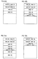
- the card is recorded with template image data ⁇ circle around ( 1 ) ⁇ , ⁇ circle around ( 2 ) ⁇ and photographed image data ⁇ circle around ( 1 ) ⁇ , ⁇ circle around ( 2 ) ⁇ , and has a sufficient vacant capacity as shown in FIG. 6 (A).
- composite image data is recorded following the photographed image data ⁇ circle around ( 2 ) ⁇ , as shown in FIG. 6 (B).
- the composite image data has an image file name “pic” that is the same as that of the photographed image data.
- the Compositae image data has an image file name “pic00003.jpg”.
- composite image data is held in the DRAM 24 prior to determining a vacant capacity of the memory card 46 so that, when a memory card with a sufficient vacant capacity is mounted, the composite image data is recorded into the memory card. Accordingly, there is no necessity of re-creating composite image data, thus eliminating troublesome operations.
- step S 28 if a step S 28 is provided that is prior to the step S 29 in order to erase the photographed image data having been used in compositing, the vacant capacity is increased by an amount corresponding to the erasure. This can reduce the necessity of exchanging the memory card to create composite image data.
- the composite image data ⁇ circle around ( 7 ) ⁇ is recorded into a newly-attached memory card. That is, the composite image data ⁇ circle around ( 7 ) ⁇ is recorded into a memory card having been recorded only with template image data ⁇ circle around ( 3 ) ⁇ ⁇ circle around ( 4 ) ⁇ , for example, as shown in FIG. 10 (C).
- the various kinds of cards involving SSFDC may be applied as a memory card.
- this embodiment employed the complementary-colored filter having Y e , C y , M g and G arranged in a mosaic form, it is possible to use a primary-colored filter having R, G and B arranged in a mosaic form.
Abstract
Description


Claims (8)
Applications Claiming Priority (2)
| Application Number | Priority Date | Filing Date | Title |
|---|---|---|---|
| JP9-157163 | 1997-06-13 | ||
| JP15716397A JP3496744B2 (en) | 1997-06-13 | 1997-06-13 | Image data recording device and digital camera |
Publications (1)
| Publication Number | Publication Date |
|---|---|
| US6721002B1 true US6721002B1 (en) | 2004-04-13 |
Family
ID=15643573
Family Applications (1)
| Application Number | Title | Priority Date | Filing Date |
|---|---|---|---|
| US09/095,573 Expired - Lifetime US6721002B1 (en) | 1997-06-13 | 1998-06-11 | Method for recording image data and digital camera using same adapted to composite a plurality of image data and record the composite image data into a memory |
Country Status (2)
| Country | Link |
|---|---|
| US (1) | US6721002B1 (en) |
| JP (1) | JP3496744B2 (en) |
Cited By (10)
| Publication number | Priority date | Publication date | Assignee | Title |
|---|---|---|---|---|
| US20030233363A1 (en) * | 2002-06-17 | 2003-12-18 | Microsoft Corporation | Combined image views and method of creating images |
| US20040006689A1 (en) * | 2002-06-17 | 2004-01-08 | Microsoft Corporation | Booting from a compressed image |
| US20040015536A1 (en) * | 2002-06-17 | 2004-01-22 | Microsoft Corporation | Multicast system and method for deploying multiple images simultaneously |
| US20040034849A1 (en) * | 2002-06-17 | 2004-02-19 | Microsoft Corporation | Volume image views and methods of creating volume images in which a file similar to a base file is stored as a patch of the base file |
| US20060007346A1 (en) * | 2004-07-12 | 2006-01-12 | Kenji Nakamura | Image capturing apparatus and image capturing method |
| US20060192862A1 (en) * | 2005-02-28 | 2006-08-31 | Fuji Photo Film Co., Ltd. | Titling apparatus, a titling method, and a machine readable medium storing thereon a computer program for titling |
| US7196805B1 (en) | 2000-12-29 | 2007-03-27 | Cisco Technology, Inc. | Consumer level device for automatically transferring digital images to an internet-based service provider |
| EP1954040A2 (en) * | 2007-02-01 | 2008-08-06 | Samsung Electronics Co., Ltd. | Method and apparatus for processing data |
| CN104683683A (en) * | 2013-11-29 | 2015-06-03 | 英业达科技有限公司 | System for shooting images and method thereof |
| US9582513B2 (en) | 2013-12-08 | 2017-02-28 | Microsoft Technology Licensing, Llc | Accessing data in a compressed container through dynamic redirection |
Families Citing this family (4)
| Publication number | Priority date | Publication date | Assignee | Title |
|---|---|---|---|---|
| JP2011041832A (en) * | 2010-11-01 | 2011-03-03 | Sanyo Product Co Ltd | Game machine |
| JP2012250093A (en) * | 2012-09-26 | 2012-12-20 | Sanyo Product Co Ltd | Game machine |
| JP2014223362A (en) * | 2014-07-01 | 2014-12-04 | 株式会社三洋物産 | Game machine |
| JP2016154975A (en) * | 2016-06-08 | 2016-09-01 | 株式会社三洋物産 | Game machine |
Citations (18)
| Publication number | Priority date | Publication date | Assignee | Title |
|---|---|---|---|---|
| US5016107A (en) * | 1989-05-09 | 1991-05-14 | Eastman Kodak Company | Electronic still camera utilizing image compression and digital storage |
| US5027214A (en) | 1989-04-20 | 1991-06-25 | Olympus Optical Co., Ltd. | Electronic still camera using variable-length data compression for storing still image signals |
| JPH05336484A (en) | 1992-05-29 | 1993-12-17 | Konica Corp | Still video camera |
| JPH0678260A (en) | 1992-08-28 | 1994-03-18 | Konica Corp | Still video camera |
| US5477264A (en) * | 1994-03-29 | 1995-12-19 | Eastman Kodak Company | Electronic imaging system using a removable software-enhanced storage device |
| JPH08140025A (en) | 1994-11-09 | 1996-05-31 | Konica Corp | Digital still camera |
| US5581311A (en) * | 1994-07-22 | 1996-12-03 | Nikon Corporation | Image storage system for a digital still camera |
| US5633976A (en) * | 1991-12-06 | 1997-05-27 | Canon Kabushiki Kaisha | Image recording apparatus and electronic still camera |
| US5633678A (en) * | 1995-12-20 | 1997-05-27 | Eastman Kodak Company | Electronic still camera for capturing and categorizing images |
| US5682202A (en) * | 1989-12-08 | 1997-10-28 | Fuji Photo Film Co., Ltd. | Apparatus for recording/reproducing video data in a memory card on a cluster basis |
| US5742339A (en) * | 1994-12-27 | 1998-04-21 | Asahi Kogaku Kogyo Kabushiki Kaisha | Electronic still video camera |
| US5867214A (en) * | 1996-04-11 | 1999-02-02 | Apple Computer, Inc. | Apparatus and method for increasing a digital camera image capture rate by delaying image processing |
| US5986700A (en) | 1994-02-16 | 1999-11-16 | Asahi Kogaku Kogyo Kabushiki Kaisha | Recording operation control device |
| US6094282A (en) * | 1989-05-17 | 2000-07-25 | Minolta Co., Ltd. | Camera capable of recording and reproducing a photographed image |
| US6111605A (en) * | 1995-11-06 | 2000-08-29 | Ricoh Company Limited | Digital still video camera, image data output system for digital still video camera, frame for data relay for digital still video camera, data transfer system for digital still video camera, and image regenerating apparatus |
| US6147703A (en) * | 1996-12-19 | 2000-11-14 | Eastman Kodak Company | Electronic camera with image review |
| US20010000969A1 (en) | 1990-12-13 | 2001-05-10 | Tadashi Ohta | Electronic still camera and method of operating same |
| US6239837B1 (en) * | 1995-09-05 | 2001-05-29 | Masayuki Yamada | Digital camera with detachable auxiliary memory |
-
1997
- 1997-06-13 JP JP15716397A patent/JP3496744B2/en not_active Expired - Fee Related
-
1998
- 1998-06-11 US US09/095,573 patent/US6721002B1/en not_active Expired - Lifetime
Patent Citations (19)
| Publication number | Priority date | Publication date | Assignee | Title |
|---|---|---|---|---|
| US5027214A (en) | 1989-04-20 | 1991-06-25 | Olympus Optical Co., Ltd. | Electronic still camera using variable-length data compression for storing still image signals |
| US5016107A (en) * | 1989-05-09 | 1991-05-14 | Eastman Kodak Company | Electronic still camera utilizing image compression and digital storage |
| US6094282A (en) * | 1989-05-17 | 2000-07-25 | Minolta Co., Ltd. | Camera capable of recording and reproducing a photographed image |
| US5682202A (en) * | 1989-12-08 | 1997-10-28 | Fuji Photo Film Co., Ltd. | Apparatus for recording/reproducing video data in a memory card on a cluster basis |
| US20010000969A1 (en) | 1990-12-13 | 2001-05-10 | Tadashi Ohta | Electronic still camera and method of operating same |
| US5633976A (en) * | 1991-12-06 | 1997-05-27 | Canon Kabushiki Kaisha | Image recording apparatus and electronic still camera |
| JPH05336484A (en) | 1992-05-29 | 1993-12-17 | Konica Corp | Still video camera |
| JPH0678260A (en) | 1992-08-28 | 1994-03-18 | Konica Corp | Still video camera |
| US5986700A (en) | 1994-02-16 | 1999-11-16 | Asahi Kogaku Kogyo Kabushiki Kaisha | Recording operation control device |
| US5477264A (en) * | 1994-03-29 | 1995-12-19 | Eastman Kodak Company | Electronic imaging system using a removable software-enhanced storage device |
| US5581311A (en) * | 1994-07-22 | 1996-12-03 | Nikon Corporation | Image storage system for a digital still camera |
| JPH08140025A (en) | 1994-11-09 | 1996-05-31 | Konica Corp | Digital still camera |
| US5742339A (en) * | 1994-12-27 | 1998-04-21 | Asahi Kogaku Kogyo Kabushiki Kaisha | Electronic still video camera |
| US6239837B1 (en) * | 1995-09-05 | 2001-05-29 | Masayuki Yamada | Digital camera with detachable auxiliary memory |
| US6515697B1 (en) * | 1995-09-05 | 2003-02-04 | Chinon Kabushiki Kaisha | Digital camera with detachable auxiliary memory |
| US6111605A (en) * | 1995-11-06 | 2000-08-29 | Ricoh Company Limited | Digital still video camera, image data output system for digital still video camera, frame for data relay for digital still video camera, data transfer system for digital still video camera, and image regenerating apparatus |
| US5633678A (en) * | 1995-12-20 | 1997-05-27 | Eastman Kodak Company | Electronic still camera for capturing and categorizing images |
| US5867214A (en) * | 1996-04-11 | 1999-02-02 | Apple Computer, Inc. | Apparatus and method for increasing a digital camera image capture rate by delaying image processing |
| US6147703A (en) * | 1996-12-19 | 2000-11-14 | Eastman Kodak Company | Electronic camera with image review |
Cited By (22)
| Publication number | Priority date | Publication date | Assignee | Title |
|---|---|---|---|---|
| US7196805B1 (en) | 2000-12-29 | 2007-03-27 | Cisco Technology, Inc. | Consumer level device for automatically transferring digital images to an internet-based service provider |
| US7017144B2 (en) * | 2002-06-17 | 2006-03-21 | Microsoft Corporation | Combined image views and method of creating images |
| US20030233363A1 (en) * | 2002-06-17 | 2003-12-18 | Microsoft Corporation | Combined image views and method of creating images |
| US7664944B2 (en) | 2002-06-17 | 2010-02-16 | Microsoft Corporation | Booting from a compressed image |
| US7464176B2 (en) | 2002-06-17 | 2008-12-09 | Microsoft Corporation | Multicast system and method for deploying multiple images simultaneously |
| US20060130017A1 (en) * | 2002-06-17 | 2006-06-15 | Microsoft Corporation | Combined image views and methods of creating images |
| US20040015536A1 (en) * | 2002-06-17 | 2004-01-22 | Microsoft Corporation | Multicast system and method for deploying multiple images simultaneously |
| US7120786B2 (en) | 2002-06-17 | 2006-10-10 | Microsoft Corporation | Booting from a compressed image |
| US20060259754A1 (en) * | 2002-06-17 | 2006-11-16 | Microsoft Corporation | Booting from a compressed image |
| US20040006689A1 (en) * | 2002-06-17 | 2004-01-08 | Microsoft Corporation | Booting from a compressed image |
| US20040034849A1 (en) * | 2002-06-17 | 2004-02-19 | Microsoft Corporation | Volume image views and methods of creating volume images in which a file similar to a base file is stored as a patch of the base file |
| US20060007346A1 (en) * | 2004-07-12 | 2006-01-12 | Kenji Nakamura | Image capturing apparatus and image capturing method |
| US20060192862A1 (en) * | 2005-02-28 | 2006-08-31 | Fuji Photo Film Co., Ltd. | Titling apparatus, a titling method, and a machine readable medium storing thereon a computer program for titling |
| US7956905B2 (en) * | 2005-02-28 | 2011-06-07 | Fujifilm Corporation | Titling apparatus, a titling method, and a machine readable medium storing thereon a computer program for titling |
| US20110199510A1 (en) * | 2005-02-28 | 2011-08-18 | Shuji Ono | Titling apparatus, a titling method, and a machine readable medium storing thereon a computer program for titling |
| US8411167B2 (en) | 2005-02-28 | 2013-04-02 | Fujifilm Corporation | Titling apparatus, a titling method, and a machine readable medium storing thereon a computer program for titling |
| US8953065B2 (en) | 2005-02-28 | 2015-02-10 | Facebook, Inc. | Titling apparatus, a titling method, and a machine readable medium storing thereon a computer program for titling |
| US20080187293A1 (en) * | 2007-02-01 | 2008-08-07 | Samsung Electronics Co., Ltd. | Method and apparatus for processing data |
| EP1954040A2 (en) * | 2007-02-01 | 2008-08-06 | Samsung Electronics Co., Ltd. | Method and apparatus for processing data |
| EP1954040A3 (en) * | 2007-02-01 | 2010-09-01 | Samsung Electronics Co., Ltd. | Method and apparatus for processing data |
| CN104683683A (en) * | 2013-11-29 | 2015-06-03 | 英业达科技有限公司 | System for shooting images and method thereof |
| US9582513B2 (en) | 2013-12-08 | 2017-02-28 | Microsoft Technology Licensing, Llc | Accessing data in a compressed container through dynamic redirection |
Also Published As
| Publication number | Publication date |
|---|---|
| JP3496744B2 (en) | 2004-02-16 |
| JPH114405A (en) | 1999-01-06 |
Similar Documents
| Publication | Publication Date | Title |
|---|---|---|
| US6556243B1 (en) | Digital camera | |
| US7733388B2 (en) | Digital camera capable of image processing for display on a monitor | |
| EP0893908B1 (en) | Digital camara | |
| US6721002B1 (en) | Method for recording image data and digital camera using same adapted to composite a plurality of image data and record the composite image data into a memory | |
| US20030076312A1 (en) | Image display control for a plurality of images | |
| JP2002077673A (en) | Electronic camera | |
| US6441850B1 (en) | Method and apparatus for image processing using a template image | |
| US7324141B2 (en) | Image sensing apparatus and data processing method used therein | |
| US5532740A (en) | Image-data recording device and image-reproduction device for an electronic still camera | |
| US6603509B1 (en) | Digital camera controllable by a program | |
| CN101543050A (en) | Imaging device, imaging method and integrated circuit | |
| US6661452B1 (en) | Digital camera capable of decreasing a required memory capacity | |
| CN102209199B (en) | Imaging apparatus | |
| JP2010021710A (en) | Imaging device, image processor, and program | |
| JP2005094298A (en) | Digital camera and image data recording method | |
| EP0886430B1 (en) | Method for arranging image numbers | |
| JP2005086744A (en) | Digital camera and control method of digital camera | |
| KR100528860B1 (en) | Screen hiding apparatus and method for particular part of digital still camera | |
| JP6594485B2 (en) | IMAGING DEVICE, IMAGING DEVICE CONTROL METHOD AND SYSTEM | |
| JPH0918828A (en) | Recording device and method and reproducing device and method for digital image data | |
| JP3253538B2 (en) | Image processing apparatus and image processing method thereof | |
| JP2005278003A (en) | Image processing apparatus | |
| JP2000101916A (en) | Electronic still camera and its control method | |
| JP3535738B2 (en) | camera | |
| JP2000299800A (en) | Image pickup method and device and storage medium |
Legal Events
| Date | Code | Title | Description |
|---|---|---|---|
| AS | Assignment |
Owner name: OLYMPUS OPTICAL CO., LTD., JAPAN Free format text: ASSIGNMENT OF ASSIGNORS INTEREST;ASSIGNORS:DOTSUBO, NOBUHIDE;HAYASHI, HIDETO;HARUKI, TOSHINOBU;AND OTHERS;REEL/FRAME:009265/0728;SIGNING DATES FROM 19980529 TO 19980605 Owner name: SANYO ELECTRIC CO., LTD., JAPAN Free format text: ASSIGNMENT OF ASSIGNORS INTEREST;ASSIGNORS:DOTSUBO, NOBUHIDE;HAYASHI, HIDETO;HARUKI, TOSHINOBU;AND OTHERS;REEL/FRAME:009265/0728;SIGNING DATES FROM 19980529 TO 19980605 |
|
| FEPP | Fee payment procedure |
Free format text: PAYOR NUMBER ASSIGNED (ORIGINAL EVENT CODE: ASPN); ENTITY STATUS OF PATENT OWNER: LARGE ENTITY |
|
| STCF | Information on status: patent grant |
Free format text: PATENTED CASE |
|
| FPAY | Fee payment |
Year of fee payment: 4 |
|
| FPAY | Fee payment |
Year of fee payment: 8 |
|
| AS | Assignment |
Owner name: XACTI CORPORATION, JAPAN Free format text: ASSIGNMENT OF ASSIGNORS INTEREST;ASSIGNOR:SANYO ELECTRIC CO., LTD.;REEL/FRAME:032462/0232 Effective date: 20140305 |
|
| FPAY | Fee payment |
Year of fee payment: 12 |
|
| AS | Assignment |
Owner name: OLYMPUS CORPORATION, JAPAN Free format text: CHANGE OF ADDRESS;ASSIGNOR:OLYMPUS CORPORATION;REEL/FRAME:039344/0502 Effective date: 20160401 |