US6725281B1 - Synchronization of controlled device state using state table and eventing in data-driven remote device control model - Google Patents
Synchronization of controlled device state using state table and eventing in data-driven remote device control model Download PDFInfo
- Publication number
- US6725281B1 US6725281B1 US09/432,853 US43285399A US6725281B1 US 6725281 B1 US6725281 B1 US 6725281B1 US 43285399 A US43285399 A US 43285399A US 6725281 B1 US6725281 B1 US 6725281B1
- Authority
- US
- United States
- Prior art keywords
- state
- computing device
- controlled
- controlled computing
- control point
- Prior art date
- Legal status (The legal status is an assumption and is not a legal conclusion. Google has not performed a legal analysis and makes no representation as to the accuracy of the status listed.)
- Expired - Lifetime
Links
Images


Classifications
-
- H—ELECTRICITY
- H04—ELECTRIC COMMUNICATION TECHNIQUE
- H04L—TRANSMISSION OF DIGITAL INFORMATION, e.g. TELEGRAPHIC COMMUNICATION
- H04L12/00—Data switching networks
- H04L12/28—Data switching networks characterised by path configuration, e.g. LAN [Local Area Networks] or WAN [Wide Area Networks]
- H04L12/2803—Home automation networks
- H04L12/2805—Home Audio Video Interoperability [HAVI] networks
-
- H—ELECTRICITY
- H04—ELECTRIC COMMUNICATION TECHNIQUE
- H04L—TRANSMISSION OF DIGITAL INFORMATION, e.g. TELEGRAPHIC COMMUNICATION
- H04L12/00—Data switching networks
- H04L12/28—Data switching networks characterised by path configuration, e.g. LAN [Local Area Networks] or WAN [Wide Area Networks]
- H04L12/2803—Home automation networks
- H04L12/2807—Exchanging configuration information on appliance services in a home automation network
- H04L12/281—Exchanging configuration information on appliance services in a home automation network indicating a format for calling an appliance service function in a home automation network
-
- H—ELECTRICITY
- H04—ELECTRIC COMMUNICATION TECHNIQUE
- H04L—TRANSMISSION OF DIGITAL INFORMATION, e.g. TELEGRAPHIC COMMUNICATION
- H04L61/00—Network arrangements, protocols or services for addressing or naming
- H04L61/30—Managing network names, e.g. use of aliases or nicknames
-
- H—ELECTRICITY
- H04—ELECTRIC COMMUNICATION TECHNIQUE
- H04L—TRANSMISSION OF DIGITAL INFORMATION, e.g. TELEGRAPHIC COMMUNICATION
- H04L61/00—Network arrangements, protocols or services for addressing or naming
- H04L61/50—Address allocation
- H04L61/5007—Internet protocol [IP] addresses
- H04L61/5014—Internet protocol [IP] addresses using dynamic host configuration protocol [DHCP] or bootstrap protocol [BOOTP]
-
- H—ELECTRICITY
- H04—ELECTRIC COMMUNICATION TECHNIQUE
- H04L—TRANSMISSION OF DIGITAL INFORMATION, e.g. TELEGRAPHIC COMMUNICATION
- H04L61/00—Network arrangements, protocols or services for addressing or naming
- H04L61/50—Address allocation
- H04L61/5092—Address allocation by self-assignment, e.g. picking addresses at random and testing if they are already in use
-
- H—ELECTRICITY
- H04—ELECTRIC COMMUNICATION TECHNIQUE
- H04L—TRANSMISSION OF DIGITAL INFORMATION, e.g. TELEGRAPHIC COMMUNICATION
- H04L67/00—Network arrangements or protocols for supporting network services or applications
- H04L67/01—Protocols
- H04L67/02—Protocols based on web technology, e.g. hypertext transfer protocol [HTTP]
-
- H—ELECTRICITY
- H04—ELECTRIC COMMUNICATION TECHNIQUE
- H04L—TRANSMISSION OF DIGITAL INFORMATION, e.g. TELEGRAPHIC COMMUNICATION
- H04L67/00—Network arrangements or protocols for supporting network services or applications
- H04L67/01—Protocols
- H04L67/12—Protocols specially adapted for proprietary or special-purpose networking environments, e.g. medical networks, sensor networks, networks in vehicles or remote metering networks
- H04L67/125—Protocols specially adapted for proprietary or special-purpose networking environments, e.g. medical networks, sensor networks, networks in vehicles or remote metering networks involving control of end-device applications over a network
-
- H—ELECTRICITY
- H04—ELECTRIC COMMUNICATION TECHNIQUE
- H04L—TRANSMISSION OF DIGITAL INFORMATION, e.g. TELEGRAPHIC COMMUNICATION
- H04L67/00—Network arrangements or protocols for supporting network services or applications
- H04L67/14—Session management
-
- H—ELECTRICITY
- H04—ELECTRIC COMMUNICATION TECHNIQUE
- H04L—TRANSMISSION OF DIGITAL INFORMATION, e.g. TELEGRAPHIC COMMUNICATION
- H04L67/00—Network arrangements or protocols for supporting network services or applications
- H04L67/50—Network services
- H04L67/51—Discovery or management thereof, e.g. service location protocol [SLP] or web services
-
- H—ELECTRICITY
- H04—ELECTRIC COMMUNICATION TECHNIQUE
- H04L—TRANSMISSION OF DIGITAL INFORMATION, e.g. TELEGRAPHIC COMMUNICATION
- H04L69/00—Network arrangements, protocols or services independent of the application payload and not provided for in the other groups of this subclass
- H04L69/30—Definitions, standards or architectural aspects of layered protocol stacks
- H04L69/32—Architecture of open systems interconnection [OSI] 7-layer type protocol stacks, e.g. the interfaces between the data link level and the physical level
- H04L69/322—Intralayer communication protocols among peer entities or protocol data unit [PDU] definitions
- H04L69/329—Intralayer communication protocols among peer entities or protocol data unit [PDU] definitions in the application layer [OSI layer 7]
-
- H—ELECTRICITY
- H04—ELECTRIC COMMUNICATION TECHNIQUE
- H04L—TRANSMISSION OF DIGITAL INFORMATION, e.g. TELEGRAPHIC COMMUNICATION
- H04L9/00—Cryptographic mechanisms or cryptographic arrangements for secret or secure communications; Network security protocols
- H04L9/40—Network security protocols
-
- H—ELECTRICITY
- H04—ELECTRIC COMMUNICATION TECHNIQUE
- H04L—TRANSMISSION OF DIGITAL INFORMATION, e.g. TELEGRAPHIC COMMUNICATION
- H04L12/00—Data switching networks
- H04L12/28—Data switching networks characterised by path configuration, e.g. LAN [Local Area Networks] or WAN [Wide Area Networks]
- H04L12/2803—Home automation networks
- H04L12/2816—Controlling appliance services of a home automation network by calling their functionalities
- H04L12/2818—Controlling appliance services of a home automation network by calling their functionalities from a device located outside both the home and the home network
-
- H—ELECTRICITY
- H04—ELECTRIC COMMUNICATION TECHNIQUE
- H04L—TRANSMISSION OF DIGITAL INFORMATION, e.g. TELEGRAPHIC COMMUNICATION
- H04L12/00—Data switching networks
- H04L12/28—Data switching networks characterised by path configuration, e.g. LAN [Local Area Networks] or WAN [Wide Area Networks]
- H04L12/2803—Home automation networks
- H04L12/2816—Controlling appliance services of a home automation network by calling their functionalities
- H04L12/282—Controlling appliance services of a home automation network by calling their functionalities based on user interaction within the home
-
- H—ELECTRICITY
- H04—ELECTRIC COMMUNICATION TECHNIQUE
- H04L—TRANSMISSION OF DIGITAL INFORMATION, e.g. TELEGRAPHIC COMMUNICATION
- H04L12/00—Data switching networks
- H04L12/28—Data switching networks characterised by path configuration, e.g. LAN [Local Area Networks] or WAN [Wide Area Networks]
- H04L12/2803—Home automation networks
- H04L2012/284—Home automation networks characterised by the type of medium used
- H04L2012/2841—Wireless
-
- H—ELECTRICITY
- H04—ELECTRIC COMMUNICATION TECHNIQUE
- H04L—TRANSMISSION OF DIGITAL INFORMATION, e.g. TELEGRAPHIC COMMUNICATION
- H04L12/00—Data switching networks
- H04L12/28—Data switching networks characterised by path configuration, e.g. LAN [Local Area Networks] or WAN [Wide Area Networks]
- H04L12/2803—Home automation networks
- H04L2012/2847—Home automation networks characterised by the type of home appliance used
- H04L2012/2849—Audio/video appliances
-
- H—ELECTRICITY
- H04—ELECTRIC COMMUNICATION TECHNIQUE
- H04L—TRANSMISSION OF DIGITAL INFORMATION, e.g. TELEGRAPHIC COMMUNICATION
- H04L12/00—Data switching networks
- H04L12/28—Data switching networks characterised by path configuration, e.g. LAN [Local Area Networks] or WAN [Wide Area Networks]
- H04L12/2803—Home automation networks
- H04L2012/2847—Home automation networks characterised by the type of home appliance used
- H04L2012/285—Generic home appliances, e.g. refrigerators
-
- H—ELECTRICITY
- H04—ELECTRIC COMMUNICATION TECHNIQUE
- H04L—TRANSMISSION OF DIGITAL INFORMATION, e.g. TELEGRAPHIC COMMUNICATION
- H04L67/00—Network arrangements or protocols for supporting network services or applications
-
- H—ELECTRICITY
- H04—ELECTRIC COMMUNICATION TECHNIQUE
- H04L—TRANSMISSION OF DIGITAL INFORMATION, e.g. TELEGRAPHIC COMMUNICATION
- H04L67/00—Network arrangements or protocols for supporting network services or applications
- H04L67/01—Protocols
- H04L67/02—Protocols based on web technology, e.g. hypertext transfer protocol [HTTP]
- H04L67/025—Protocols based on web technology, e.g. hypertext transfer protocol [HTTP] for remote control or remote monitoring of applications
Definitions
- This invention relates generally to dynamic connectivity among distributed devices and services, and more particularly relates to providing a capability to access device- or service-specific operational information and perform remote automation and control of embedded computing devices using a data-driven remote programming model, such as in a pervasive computing environment
- the cost of computing and networking technologies have fallen to the point where computing and networking capabilities can be built into the design of many electronic devices in the home, the office and public places.
- the combination of inexpensive and reliable shared networking media with a new class of small computing devices has created an opportunity for new functionality based mainly on the connectivity among these devices.
- This connectivity can be used to remotely control devices, to move-digital data in the form of audio, video and still images between devices, to share information among devices and with the unconstrained World Wide Web of the Internet (hereafter “Web”) and to exchange structured and secure digital data to support things like electronic commerce.
- Web World Wide Web
- the connectivity also enables many new applications for computing devices, such as proximity-based usage scenarios where devices interact based at least in part on geographical or other notions of proximity.
- a prevalent feature of these connectivity scenarios is to provide remote access and control of connected devices and services from another device with user interface capabilities (e.g., a universal remote controller, handheld computer or digital assistant, cell phones, and the like).
- user interface capabilities e.g., a universal remote controller, handheld computer or digital assistant, cell phones, and the like.
- a device with user interface capabilities controls an exchange of data between image, video, and audio capture devices (e.g., cameras and recorders) and recording, play-back and presentation devices (e.g., a television, printer, and data storage devices).
- image, video, and audio capture devices e.g., cameras and recorders
- recording, play-back and presentation devices e.g., a television, printer, and data storage devices.
- the user interface experience of a controlled device's physical control panel e.g., the buttons, knobs and display of an audio/video equipment's front panel and infrared remote
- controlled devices in a device control model maintain a state table representative of their operational state.
- Devices that provide a user interface or user control point for the controlled device obtain the state table of the controlled device, and may also obtain presentation data defining presentation of the remoted user interface of the controlled device and device control protocol data defining commands and data messaging to effect control of the controlled device.
- These user control point devices also subscribe to notifications of state table changes, which are distributed from the controlled device according to an eventing model. Accordingly, upon any change to the controlled device's operational state caused by user inputs from any user control point device or even the controlled device's front panel or infrared remote, the device's state as represented in the state table is synchronized across all these user control point devices using the eventing model.
- the device state table and eventing model enable dynamic and automatic synchronization of the device state among all interested controllers that subscribe to notifications of the controlled device's state upon a change in the controlled device's state, whether the device commands that cause a change in device state originate from other user control point devices or directly through front panel or infrared remote of the controlled device itself.
- This synchronization of the controlled device's state among all user control point devices that provide a user interface to the controlled device allows these user control point devices to present a consistent and correct depiction of the controlled device's state in their user interface. This way the user is able to interact appropriately to the actual current state of the device, e.g., avoiding issuing a “toggle power on/off” command when the controlled device's power already is on.
- the controlled device thus is able to truly remote its direct front panel/infrared remote user interface as a virtual user interface on other user control point devices in a distributed network.
- the device state table also may contain entries that are a byte block or data buffer, in which a file can be loaded.
- the device state table and eventing model enable a file transfer from the controlled device to interested subscribing devices via loading of the file into the data buffer entry of the device state table. Since the eventing model can broadcast any change to the data state table, the eventing model can effect an immediate file transfer upon any change in the file. Further, multiple files can be transferred by loading one at a time into this data buffer entry of the device state table.
- FIGS. 1 and 2 are block diagrams of a device architecture per Universal Plug and Play using user control points, controlled devices and bridges for connectivity between devices.
- FIG. 3 is a block diagram of a device model per Universal Plug and Play.
- FIG. 4 is a block diagram illustrating example devices conforming to the device model of FIG. 3 .
- FIG. 5 is a block diagram illustrating device state synchronization using a state table and eventing.
- FIG. 6 is a block diagram illustrating device addressing.
- FIG. 7 is a block diagram of a programmatic interface-to-network messaging adapter or Rehydrator in the device control model of FIG. 3 .
- FIG. 8 is a general data flow diagram of the Rehydrator of FIG. 7 in the device control model of FIG. 3 .
- FIG. 9 is a block diagram of an implementation design of the Rehydrator of FIG. 7 .
- FIGS. 10 and 11 are block diagrams illustrating an internal software architecture of the user control point and controlled device in the device control model of FIG. 3 .
- FIG. 12 is a block diagram illustrating an internal software architecture of a combined bridge and user control point in the device control model of FIG. 3 .
- FIG. 13 is a data flow diagram illustrating a typical browsing protocol sequence in the device control model of FIG. 3 .
- FIG. 14 is a listing showing a layout of a description document in the device control model of FIG. 3 .
- FIG. 15 is a listing of an exemplary icon list of a Description Document in the device control model of FIG. 3 .
- FIG. 16 is a listing of an exemplary service control protocol declaration in a Description Document in the device control model of FIG. 3 .
- FIGS. 17, 18 , and 19 are a listing of an exemplary contract in the device control model of FIG. 3 .
- FIGS. 20 and 21 are a listing of an XML schema for a Service Control Protocol Declaration Language used in the device control model of FIG. 3 .
- FIG. 22 is a block diagram of an eventing model used in the device control model of FIG. 3 .
- FIG. 23 is a data flow diagram illustrating subscription, notification and unsubscription in the eventing model of FIG. 22 .
- FIG. 24 is a block diagram of a computer system that may be used in the device control model of FIG. 3 .
- FIG. 25 is a block diagram of a device having embedded computing and networking capability per universal-plug-and-play (UPNP) standards that may be used in combination with the computer system of FIG. 24 in the device control model of FIG. 3 .
- UPNP universal-plug-and-play
- FIG. 26 is a block diagram of a software architecture per UPNP standards in the embedded computing device of FIG. 25
- FIG. 27 is a data flow diagram of a process for automatic network introduction of the embedded computing device of FIG. 25 into an ad hoc computer network environment per the UPNP protocol.
- FIG. 28 is a data flow diagram of a process for automatic network introduction of the embedded computing device of FIG. 25 into a configured computer network environment per the UPNP protocol.
- FIG. 29 is a block diagram of a software architecture of a client device per UPNP standards having embedded computing and networking capability that may be used in the device control model of FIG. 3 .
- FIG. 30 is a block diagram of an exemplary home or office pervasive computing environment having a variety of computers as per FIG. 24 and embedded computing devices as per FIG. 25 interconnected per UPNP standards that may be used in the device control model of FIG. 3 .
- FIGS. 31 through 43 are program listings of interfaces used in the Rehydrator implementation design of FIG. 9 .
- FIGS. 44-46 are an XML format listing that depicts an exemplary contract for interacting with a stock quote Service.
- FIGS. 47-50 are an XML format listing that depicts an XML schema for defining Contracts.
- this device state and eventing is used in a device architecture 100 (FIG. 1 ), connectivity model, and device control protocol proposed by Microsoft Corporation, called Universal Plug and Play (“UPnP”).
- FPGA Universal Plug and Play
- UnP Universal Plug and Play
- PnP Plug and Play
- a suitable communication architecture must enable a highly dynamic connectivity model and must enable peer-to-peer operating among arbitrary combinations of devices.
- the Internet has created a widespread awareness of the value of simple, universal communication that is independent of the underlying transmission technology and independent of technology from any single vendor.
- UPnP makes it possible to initiate and control the transfer of bulk data (e.g. files) or A/V data streams from any device on the network, to any device on the network, under the control of any device on the network.
- UPnP enables the ad hoc addition or removal of devices on the network, and it enables multiple controlling devices to remain in sync with each other.
- UPnP reuses existing protocols and technology whenever possible. The transition to this highly connected (and connectable) world will not occur overnight.
- UPnP builds on existing Internet protocols, but accommodates devices that cannot run the complete UPnP protocol suite.
- UPnP provides an architecture that enables legacy devices to communicate with UPnP devices.
- IP internetworking has been chosen as a UPnP baseline due to its proven ability to span different physical media, to enable real world multiple vendor interoperation and to achieve synergy with the Internet and home and office intranets.
- Internet synergy enables applications such as IP telephony, multiple player games, remote control of home automation and security, Internet based electronic commerce, in addition to simple email and web browsing.
- UPnP's scope includes remote control of devices and bulk data transfer. But, it does not specify A/V streaming formats or protocols.
- UPnP's media independence enables a great deal of flexibility in the packaging of products.
- UPnP enables an A/V system to be controlled through an A/C power communications technology, while the transmission of A/V streams among the components is analog or digital.
- One of the controllers of this system could be on the television, while another is on a PC, and yet another connected via radio or infrared.
- Networking in this context, describes a style of connectivity that enables any networked device to initiate a communication with any other networked device, without having established a prior relationship or maintaining a persistent relationship between the devices. Networking also allows multiple devices to establish one or more connections with a single device, and it allows for a device to be capable of both initiating and accepting connections to/from other devices.
- the PnP, or host/peripheral, model is suitable whenever there is a natural persistent relationship between two devices (e.g. a keyboard, mouse and display maintain and a persistent relationship with a host computer). Even though networking does not mandate low level persistent relationships, it provides the needed anchors (addresses) for applications to choose to maintain associations as a convenience for the customer (e.g. remembering commonly used networked printers).
- vendors desirably agree on common technology and standards up to the highest level of desired functional interoperation.
- Protocols contracts enable real-world multiple-vendor interoperation.
- UPnP enables devices to expose a user interface by leveraging browser technology.
- the browser can be considered to be a very rich remote terminal.
- Current browser technology does not maintain a separation of presentation from data, or in the case of devices, control. It is possible to hunt through a page of HTML to extract data values, but it is not convenient or robust.
- UPnP leverages the separation of presentation and data enabled by the use of XML, and it extends this technology to the device control domain.
- UPnP provides a device-driven auto-configuration capability that preserves the experience that customers have on the web.
- Today it is possible to navigate around the web without loading programs beyond the browser itself.
- UPnP enables the browser to be extended to control devices, and because UPnP devices are controlled with explicit protocols, the browser must somehow learn how to talk to UPnP devices. This learning process is driven entirely from the device itself and is accomplishing entirely by uploading an XML document that describes the capabilities of the device.
- the architectural component that enables device-driven auto-configuration is called the Rehydrator.
- the job of the Rehydrator is to convert between APIs and protocols.
- UPnP enables application control in addition to browser control of devices. This is achieved simply by enabling applications to call the same Rehydrator APIs that the browser does. Applications can also directly generate and consume the raw UPnP control protocols, provided they are not interested in the device-driven auto-configuration enabled by the Rehydrator.
- UPnP assumes that there will be more than one device with UI that wants to control other devices in any given network, and it provides a simple mechanism that enables these control points to remain in sync. This mechanism can easily support device front panels and wireless remotes that do not run UPnP protocols.
- the UPnP control model is third-party control; any device can transfer bulk data (e.g. files) or A/V data streams from any device on the network, to any device on the network, under the control of any device on the network.
- Module A component of a device, software program, or system that implements some “functionality”, which can be embodied as software, hardware, firmware, electronic circuitry, or etc.
- User Control Point The set of modules that enable communication with a UPnP Controlled Device. User Control Points initiate discovery and communication with Controlled Devices, and receive Events from Controlled Devices. User Control Points are typically implemented on devices that have a user interface this user interface is used to interact with Controlled Devices over the network.
- the modules minimally include a Discovery Client, a Description Client and a Rehydrator. User Control Points may also include Visual Navigation, an Event Subscription Client, Event Sink, a web browser and an application execution environment. User Control Points can add value to the network by aggregating the control of multiple Controlled Devices (the universal remote) or they can implement a function as simple as initiating the transfer of data to or from a Controlled Device.
- Examples of devices that could be User Control Points are the personal computer (PC), digital television (DTV), set-top box (STB), handheld computer and smart mobile phone, and the like. None prevents a single device from implementing the functionality of a User Control Point and one or more Controlled Devices at the same time.
- Controlled Device The set of modules that enable communication with a User Control Point. Controlled Devices respond to discovery requests, accept incoming communications from User Control Points and may send Events to User Control Points. Devices that support Controlled Device functionality may also support local user interfaces such as front panel displays or wireless remotes.
- the modules minimally include a Discovery Server, a Description Server and a Control Server. Controlled Devices may also include a Presentation (web) Server, Event Subscription Server and Event Source. Examples of devices that could be Controlled Devices are the VCR, DVD player or recorder, heating/ventilation/air-conditioning equipment (HVAC), lighting controller, audio/video/imaging playback device, handheld computer, smart mobile phone and the PC, and the like. None prevents a single device from implementing the functionality of a User Control Point and one or more Controlled Devices at the same time.
- HVAC heating/ventilation/air-conditioning equipment
- Bridge A set of modules that enables Bridged and Legacy Devices to interact with native UPnP devices.
- the bridge itself exposes a collection of UPnP Controlled Devices to User Control Points.
- the Bridge maps between native UPnP Device Control Protocols and the underlying protocols exposed by the Bridged and Legacy Devices.
- such a device could expose UPnP Controlled Devices to Legacy Devices in the manner required by the Legacy Devices.
- a module used by a UPnP Bridge that translates between UPnP protocols and the protocols used by Bridged and Legacy Devices. No Service Providers are required for communication among native UPnP devices.
- Bridged Device A device that cannot participate in UPnP at the native protocol level, either because the device does not have sufficient resources or because the underlying media is unsuitable to run TCP and HTTP. Examples of devices that could be Bridged Devices are power line-controlled AN equipment, light switches, thermostats, wristwatches and inexpensive toys. Bridged Devices are UPnP complaint and are exposed to other UPnP devices through a UPnP Bridge.
- the Device Model The UPnP model of Controlled Devices.
- the Device Model includes the addressing scheme, Description Document, Devices and Services hierarchy and the functional description of modules.
- DCP Device Control Protocol
- a Device Definition The formal definition of a Device Type.
- a Device Definition includes a Device Type Identifier, the fixed elements in the Description Document, the required set of Service Definitions in the Root Device, and the hierarchy of required Devices and Service Definitions.
- Service Definition The formal definition of a Service Type.
- a Service Definition includes a Service Type Identifier, definition of the Service State Table (SST), definition of the Service Command Set, the Service Control Protocol (SCP) and Service Control Protocol Declaration (SCPD).
- SST Service State Table
- SCP Service Control Protocol
- SCPD Service Control Protocol Declaration
- a Device In the context of the Device Model, a container for Services.
- a Device generally models a physical entity such as a VCR, but can also represent a logical entity.
- a PC emulating the traditional functions of a VCR would be an example of a logical device.
- Devices can contain other Devices.
- An example would be a TV/VCR packaged into a single physical unit.
- UPnP enables the association of user interface (display icon and root web page) with every Device, including Root Device.
- Root Device The topmost Device in a hierarchy of nested Devices. A Device with no nested Devices is always a Root Device.
- Device Type A relatively high level classification of Devices with common functionality. Device Type is intended to enable Devices to be simply and automatically grouped for presentation. An example of a Device Type is “VCR”. Device Types are formally defined in terms of a required set of Service Definitions of minimum version that a compliant Device must support. UPnP supports searches for all Devices of a specified Device Type.
- URI Uniform Resource Identifier
- Device Friendly Name A human readable string that is initialized by vendors at the time of manufacturer of a Device. Every Device, including Root Devices, has a Device Friendly Name. A typical Device Friendly Name will contain manufacturer and model information, and is used to enable a more precise identification of a UPnP Device from the set of discovered Devices. Once identified, the Unique Device Name (UDN) can be used to unambiguously identify the same Device in the future. UPnP enables Device Friendly Names to be changed by User Control Points. The Device Friendly Name should not be used as device identifier.
- UDN Unique Device Name
- Description Document A structured unit of data that is used by a User Control Point or UPnP Bridge to learn the capabilities of a Controlled Device. Description Documents are retrieved from the Description Server on a UPnP Controlled Device. There is one Description Document for every Root Device that describes the Root Device and all non-Root Devices. Description Documents adhere to XML grammar. To support localization, multiple Description Documents can exist. A User Control Point requests the preferred localized Description Document by using the standard HTTP “accept-language” header.
- Service The fundamental UPnP controllable entity (but not the finest level of control).
- An example of a Service is “Clock”. Services are defined with a mandatory common base set of functionality. Vendors can extend the base set with proprietary extensions provided the base functionality is implemented. Service Definitions are versioned and later versions are constrained to be supersets of previous versions. UPnP enables searches for all Devices that contain a specified Service of a minimum version. This search would find all clocks, regardless of their packaging. A search for Device Type “Clock” would be used to find only stand-alone clocks.
- Service Type A classification of Services by their function.
- URI Uniform Resource Identifier
- SST Service State Table
- a logical table consisting of rows of [Variable, Type, Legal Values, Default Value, Current Value] that represents the current electrical, mechanical and/or logical state of a Service.
- SST instances are stored on the Controlled Device itself and are the ultimate authority of the state of the Service. All local user interface, such as front panels or wireless remotes are required to update the SST on UPnP compliant devices.
- SCP Service Control Protocol
- SCP Service Control Protocol
- SST Definition The protocol used to invoke Commands against a Service and to return results.
- SCPs adhere to the grammar of SCP XML schema.
- SCPs can be generated by an automated tool that accepts a SST Definition and a Command Set Definition as input.
- SCPD Service Control Protocol Declaration
- the SCPD declares the rows of a Service's SST and the associated Command Set.
- SCPDs are uploaded from Controlling Devices in their Description Documents and enable User Control Points or Bridges to invoke Commands on the Service without any prior or persistent knowledge of the capabilities (or schema) of the Service.
- SCPDs adhere to XML grammar. SCPDs can be generated by an automated tool that accepts a SST Definition and a Command Set Definition as input.
- Event An unsolicited message generated by a Controlled Device and delivered to one or more User Control Points. Events are used to maintain a consistent view of the state of Service across all interested User Control Points. UPnP leverages the GENA event architecture (see “Generic Event Notification”) to transport event messages. All events are delivered using TCP/IP for reliability.
- GAA Generic Event Notification
- SSDP Simple Service Discovery Protocol
- UPnP uses SSDP to allow User Control Points to find Controlled Devices and Services.
- SSDP operates in a default, completely automatic multicast UDP/IP based mode in addition to a server-based mode that uses TCP/IP for registrations and query. Transitions between the default dynamic mode and server-based mode are automatic and transparent.
- SSDP enables every Controlled Device to control the lifetime that its Description URL is cached in all User Control Points. This enables a Controlled Device to remain visible to User Control Points for a relatively long time (through power cycles), in addition to enabling a Controlled Device to appear and disappear very quickly, all under the control of the Controlled Device.
- Client refers to a module that initiates a TCP/HTTP connection to a peer HTTP server.
- Server refers to an HTTP server. This is a module that accepts incoming TCP/HTTP connections and either returns a web page or forwards the payload data to another module.
- Client and Server describe only the direction of initiation of TCP/HTTP connections. There is no relationship between the low level concepts of Client and Server and the high level concepts of User Control Point and Controlled Devices. Logically, User Control Points always discover and initiate communication with Controlled Devices, but this communication requires Client and Server functionality on both sides.
- Hostname is the Domain Name System (DNS) or NetBIOS Name Service (NBNS) that, when resolved to an IP address, represents a network interface that can be used to establish TCP/IP level connectivity to User Control Points, Controlled Devices or Bridges.
- DNS Domain Name System
- NBNS NetBIOS Name Service
- Hostnames can be used to provide persistent network level addressing on a network where IP addresses are dynamically assigned and of unknown lifespan or to integrate with an existing managed network.
- UPnP provides an algorithm for seeding a device's hostname from its UDN at manufacturing time.
- URL Uniform Resource Locator
- Description URL The URL returned from a Controlled Device or Bridge in response to any UPnP SSDP query. This URL always points to a Description Server on the Controlled Device. An HTTP GET can be issued on this URL to retrieve the Description Document. This URL is valid as an address for the lifetime of the Hostname embedded in the URL.
- This Server The module that runs in a Controlled Device or Bridge that responds to SSDP queries. This Server is unique in that it must support UDP/HTTP rather than just TCP/HTTP.
- Description Server The module that runs in a Controlled Device or Bridge that responds to HTTP GETs and returns Description Documents.
- This service consists of a TCP/HTTP server than can retrieve and return a Description Document from persistent storage (like a filesystem).
- Visual Navigation User Control Point functionality that displays the icons of discovered Devices and enables the transfer of control to a browser or application to interact with the Controlled Device.
- Visual Navigation could be implemented as a folder of icons.
- Presentation Server A web server.
- the Presentation Client A web browser extended with a Rehydrator.
- Control URL A URL that can be used by a User Control Point to navigate to the Control Server of a Controlled Device or Bridge. This URL is returned in the Description Document and is valid as an address for the lifetime of the Hostname embedded in the URL. All Services have an associated Control URL.
- Control Server The module that runs in a Controlled Device or Bridge that responds to Commands invoked on a Service by a User Control Point. Commands are encoded using the SCP specified in the Service Definition.
- This service consists of a TCP/HTTP server than passes control to the native control logic of a Service, updates the SST and generates an event if the SST changes.
- the Control Client In UPnP, the Control Client. A User Control Point module that translates between native operating system APIs and SCPs and events. The Rehydrator uploads SCPDs from Controlled Devices and Bridges and generates appropriate SCPs in response to application API requests to invoke Commands.
- Event Subscription URL A URL that can be used by a User Control Point to navigate to the Event Subscription Server of a Controlled Device or Bridge. This URL is returned in the Description Document and is valid as an address for the lifetime of the Hostname embedded in the URL. All Services have an associated Event Subscription URL.
- Event Subscription Server The module that runs in a Controlled Device or Bridge that responds to GENA SUBSCRIBE requests from User Control Points.
- a SUBSCRIBE informs the Controlled Device or Bridge of the User Control Point's desire to receive future events.
- This service consists of a TCP/HTTP server that adds the User Control Point's Event Sink URL to the list of destinations to be NOTIFY'd whenever the SST associated with the Service changes.
- Event Subscription Client The module that runs in a User Control Point that sends GENA SUBSCIBE messages to the Event Subscription Server.
- Event Sink URL A URL, supplied by a User Control Point, that is used as an address to send event NOTIFYs to. This URL is valid as an address for the lifetime of the Hostname embedded in the URL. There is no explicit relationship between Event Sink URLs and Subscription Identifiers.
- Subscription Identifier A header in the GENA NOTIFY message that identifies the source of an event. In UPnP, the SID can be considered as an alias for the Event Source instance.
- Event Sink The module that runs in a User Control Point that accepts incoming GENA event NOTIFYs.
- This service consists of a TCP/HTTP server that passes the event information to interested applications running on the User Control Point.
- Event Source The module that runs in a Controlled Device or Bridge that sends GENA NOTIFYs to the Event Sink Servers of SUBSCRIBES User Control Points.
- DNS Domain Name System
- NBNS NetBIOS Name Server
- MDNS Multicast DNS
- SSDP Simple Service Discovery Protocol
- TCP/IP provides the ability to initiate a connection with a specified application running on a specific device, provided both the network address of the device (IP address) and the application address (port) are known.
- IP address network address
- port application address
- IP address network address of the device
- port application address
- Simple Service Discovery Protocol is a protocol that enables devices to learn of the existence of potential peer devices and the required information (an IP address) needed to establish TCP/IP connections to them.
- IP address an IP address
- the successful result of an SSDP search is a Uniform Resource Locator (URL).
- the Hostname embedded in the URL can be resolved to an IP address that can be used to make a connection to the discovered device.
- the name to address resolution is outside of the functionality of SSDP.
- SSDP specifies a default, completely automatic, best-effort multicast UDP-based operating mode, in addition to a server mode that uses TCP for registration and query. Fall-forward to server mode and fallback to the default dynamic mode can occur automatically and transparently as a server is added or removed from a network. Server mode can be used to reduce network traffic, to implement searches based on location or policy and to integrate with a directory system.
- SSDP requires that all devices specify a maximum lifetime that SSDP level knowledge of the device will remain cached in other network devices. If a device does not refresh the cache of other network devices before this interval expires, the device will disappear from the network. This interval can be chosen to be larger than a typical power down cycle to enable device visibility to persist for a relatively long time, or a smaller interval can be chosen to enable more dynamic visibility control. In all cases, devices that are abruptly removed from the network will eventually disappear from all networked devices.
- UPnP devices In response to an SSDP search, UPnP devices return a Description URL in the SSDP Location and optionally the Alternate Location (AL) SSDP headers.
- An example location header is a follows:
- the device.local is the Hostname of the Controlled Device
- the “description/path/description.xml” element of the URL is the path and name of the Description Document on the device.
- Eventing in the context of UPnP, is the ability for a device to initiate a connection at any time to one or more devices that have expressed a desire to receive events from the source device. Events are used to enable synchronization among multiple devices organized into a many to one relationship. UPnP events are mainly used for asynchronous notifications of state changes.
- TCP/IP provides the fundamental support for the connections that carry event information.
- Generic Event Notification adds conventions for establishing relationships between interested devices and an addressing scheme to enable the unambiguous delivery of events.
- GENA leverages HTTP addressing and encapsulation.
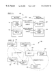
- UPnP is an application-level distributed network architecture where the logical nodes on the network are User Control Points 104 - 105 , Controlled Devices 106 - 107 and Bridges 120 . These classifications refer to functionality rather than physical entities. The functionality of UPnP User Control Points 104 - 105 , Controlled Devices 106 - 107 and Bridges 120 can be packaged into physical entities (e.g., multiple function devices 102 - 103 ) in any combination.
- the primary distinction between a User Control Point 104 - 105 and a Controlled Device 106 - 107 is that the User Control Point is always the communication initiator. After the initial communication, User Control Points can receive events from Controlled Devices.
- Controlled Devices 106 - 107 are responsible for storing the state of Services. User Control Points are required to synchronize to the state on Controlled Devices and to share state directly among themselves.
- User Control Points typically have user interface that is used to access one or more Controlled Devices on the network. Controlled Devices only have local user interfaces.
- Bridges 120 (FIG. 2) expose devices that do not expose native UPnP protocols as native UPnP Controlled Devices.
- the Bridge itself looks to other UPnP User Control Points like a set of Controlled Devices.
- Controlled Device Function Module Function Module Initiate discovery Discovery Client Respond to Discovery of Controlled discovery Server Devices. requests. Retrieve Description Client Provide Description Description Description Server Documents. Documents. Display a folder Visual Navigation of icons per discovered Device and allow transfer of control to a selected device. View user Web Browser Provide user Presentation interface exposed inteface for (Web) Server by a Controlled remote User Device. Control Points. Execute Application applications. Execution Environment Invoke Rehydrator Accept Control Server Commands on a incoming plus native Controlled Device Commands in control logic by sending SCPs and Service Control execute them. Protocols in response to local API calls. Inform a Event Accept requests Event Controlled Device Subscription for Events Subscription of a desire to Client and remember Server receive Events. them. Receive an Event. Event Sink Send an Event. Event Source
- the UPnP Device Model 200 shown in FIG. 3 is the model of a UPnP Controlled Device or Bridge that is emulating native Controlled Devices.
- the Device Model includes the addressing scheme, eventing scheme, Description Document schema, Devices and Services schema and hierarchy, and the functional description of modules.
- the UPnP Device Model extends beyond simple API or a command and control protocol definitions to enable multiple User Control Points to have a consistent view of Controlled Devices. This requires that the state of running services be formally modeled and that all state changes be visible to User Control Points.
- Central to the distributed UPnP architecture is the rule that Controlled Devices are the ultimate authority for the state of Services running on them.
- the fundamental controllable entity in UPnP is a Service 210 - 217 . Every running instance of a Service includes:
- a Service State Table (SST) 230 which represents the current state of the Service.
- the SST 230 can be used to represent the operational mode of device or to act as an information source or sink for structured data or simple files.
- the SST of a VCR 254 (FIG. 4) could represent the current transport mode, tuner channel selection, input and output switch selections, audio and video decoding format and current timer program.
- the SST of clock 251 (FIG. 4) would likely represent the current time.
- the SST of an image rendering device could implement a video frame-buffer that can accept raw pixel information or formatted JPG files.
- the SST of an audio or video playback device could implement a transfer buffer or queue of material to be played.
- the SST of PDA could implement a collection of formatted data that has changed and needed to be synchronized with another device, in addition to a transfer buffer for accepting incoming formatted data.
- a Control Server 232 which accepts incoming Commands expressed in the Service's Service Control Protocol (SCP).
- SCP Service's Service Control Protocol
- the Control Server passes the command to the Service's native command processing logic and waits for command completion.
- the SST is updated, an event is generated, and a successful response is returned to the User Control Point.
- no changes are made to the SST and a failure response is returned.
- the Command and response sequence is payload to a TCP/HTTP request/response.
- the Event Subscription Server accepts incoming GENA SUBSCRIBE messages from User Control Points and adds them to a list of User Control Points interested in SST change events from the Service.
- the Event Source initiates a TCP/HTTP connection to each interested User Control Point and sends a GENA NOTIFY each time the Service's DST changes.
- the NOTIFY payload includes the changed contents of the DST.
- a Control URL that identifies the Control Server.
- the formal definition of a Service includes:
- SST layouts are logically specified in terms of rows of [Variable, Type, Legal Values, Default Value].
- the actual instance of a SST would also include a Current Value field in every row.
- SCPD Service Control Protocol Declaration
- An automated tool that accepts the SST definition and Command Set definition as inputs can generate the SCP for a Service.
- the SCP can also be generated from the SCPD.
- the Rehydrator's job is to convert SCPDs into SCPs.
- the reason for a formal SCP specification is to enable the implementation of the Control Server itself and to enable simple peer-to-peer device interoperation using only published protocols.
- Service Type Identifier An identifier that identifies a unique Service Definition. Service Definitions are versioned in controlled manner. Every later version of a Service must be proper superset of the previous version.
- a UPnP Device 202 - 205 (e.g., multiple function devices 102 - 103 of FIG. 1 and bridged devices 122 - 123 of FIG. 2) is a logical container of one or more Services 210 - 217 .
- a Device represents a physical entity such as a VCR.
- Typical Services in the VCR Device example might be “TRANSPORT”, “TUNER”, “TIMER” and “CLOCK”. While Devices are often physical entities, a PC emulating the traditional functions of a VCR could also be modeled in the same way as the stand-alone VCR. Devices can contain other Devices.
- An example would be a TV/VCR 250 (FIG.
- a Device (e.g., devices 202 - 203 ) may also be a logical container of other Devices.
- the top-most Device in a hierarchy of nested Devices 203 - 205 is called the Root Device 202 .
- a Device with no nested Devices is always a Root Device.
- the UPnP Device Model was designed to be general and flexible. It should be possible to model an entire Nuclear Power Plant as a single Service or as a deeply nested hierarchy of Devices and Services.
- a Service 210 - 217 is cohesive set of functions that enables flexible packaging into a variety of Devices. Services can be versioned independently of Devices.
- Root Devices belong to one or more Device Types.
- Device Types are intended to enable instances of Devices to be simply and automatically grouped for presentation.
- An example of a Device Type is “VCR” 254 (FIG. 4 ).
- Device Types are formally defined in terms of a minimal set of versioned Services that a Device of Device Type must support. Device Types are not formally versioned. Device Type is a relatively high level grouping. A Device of Device Type only ensures that minimal set of Services of a minimal version is present. There can be other Services, higher versioned Services and Services with vendor extensions present on such a Device.
- UPnP enables SSDP level searches for a unique instance of a Device (by UDN), all Devices of type Device Type and all Devices that contain at least one Service Type of minimum version.
- the result of an SSDP search is always a URL that points to the Description Document contained in the Root Device.
- the Description Document has a tree of nested Devices that can be traversed to find the matching Device.
- Every Device includes:
- One or more Device Types are One or more Device Types.
- one or more Devices are configured to:
- a Presentation (web) Server 220 - 223 that can be used to expose Device user interface. Every Presentation Server has an associated Presentation URL.
- UDN Unique Device Name
- Every Root Device 202 also includes the Description Document 226 and Description Server 228 for all Devices under and including itself.
- the formal definition of a Device includes:
- the formal definition of a Device Type includes:
- a Device Type Identifier A Device Type Identifier.
- a Service State Table (SST) logically consists of rows of:
- entries of the Service State Table in UPnP consist of these five items, the state table alternatively can contain fewer or additional items. Generally, each entry will minimally consist of a Variable name or identifier, and its current value.
- Type Description Example String A sequence of UNICODE characters. Number A number, with no limit on digits; may 15, 3.14, potentially have a leading sign, ⁇ 123.456E+10 fractional digits, and optionally an exponent. Punctuation as in US English. Boolean TRUE or FALSE. DateTime A date in ISO8601 format, with 19941 105T08:1 optional time and optional zone. 5:5 +03 Fractional seconds may be as precise as nanoseconds. See, “Data elements and interchange formats - Information interchange - Representation of dates and times”, which can be found at http:www.iso.ch/markete/8601.pdf . ByteBlock An unstructured sequence of bytes.
- the ByteBlock is essentially a data buffer.
- a variable of this type can be used to effect transfer of a file from the Controlled Device to the User Control Point.
- the file to be transferred is kept in the Service State Table as the current value of this variable.
- the file is transferred to any subscribing User Control Point in an event notification.
- An SST can be used to represent to current operational mode of device, act as an information source or sink and/or simply be a repository for commands.
- the SST of a VCR Service could represent the current transport mode, tuner channel selection, input and output switch selections, audio and video decoding format and current timer program.
- the VCR 254 could be represented as a Transport Service 260 , Tuner Service, I/O Switch Service, A/V Decoding Configuration Service and Programmable Timer Service 261 .
- the SST of a clock 251 would likely represent the current time. Additionally an alarm clock could include Service Variables to configure the clock.
- the SST of an image rendering device could implement a video frame-buffer that can accept raw pixel information or formatted JPG files.
- the SST of an audio or video playback device could implement a transfer buffer or queue of material to be played.
- the SST of PDA could implement a collection of formatted data that has changed and needed to be synchronized with another device, in addition to a transfer buffer for accepting incoming formatted data.
- UPnP rules require that every change to an SST generate a corresponding event to announce the change to the all interested User Control Points.
- URLs minimally contain an identification of the application protocol family (“http”) that the URL is valid for, a Hostname and a path.
- http application protocol family
- the path part of a URL can represent either a filesystem path or simply an identifier of the local system module and context that can process incoming messages.
- UPnP modules are described as HTTP servers, there is no requirement that implementations be based on actual web servers. In most cases, the job of the HTTP server is simply to accept the incoming connection, look at the local destination part of the address (the path) and forward the payload to another module. UPnP enables, but does not require, that all HTTP Servers be based on a common software implementation or runtime instance. Controlled Devices and Bridges can include a TCP port specification as part of a URL to override the default value of 80.
- the successful result of a UPnP SSDP level search is always one or more Description URLs. These URLs can be used to navigate to the Description Document of a Controlled Device or Bridge.
- a User Control Point uploads the Description Document and extracts the URLs of the Servers running on the Controlled Device or Bridge.
- the lifetime of a Description URL is determined by Controlled Device or Bridge that advertises it. If a Controlled Device or Bridge allows an SSDP advertisement of a Description URL to expire, the URL is invalidated.
- Event Subscription URL returned by the Controlled Device or Bridge to connect to the Event Subscription Server.
- This server does the housekeeping of remembering all User Control Points that are interested in receiving Events on a Service.
- the Event Subscription Server needs an address to send the events back to. This address is called the Event Sink URL, and is supplied to the Controlled Device or Bridge in the GENA SUBSCRIBE message.
- the lifetime of an event subscription, and the Event Sink URL is determined by the timeout on the SUBSCRIBE message.
- UPnP enables SSDP searches for a unique Root or non-Root Device by UDN, devices of a specified Device Type and devices containing a Service of a specified Service Type.
- a unique Root A single Description URL pointing to the Description Device (by Server and Document path on the Root Device.
- UDN A unique non- A single Description URL pointing to the Description Root Device (by Server and Document path on the Root Device that UDN) contains the non-Root Device.
- Type of Device A set of Description URLs pointing to the Description Servers/Document paths of all Root Devices that match the Device Type, or contain a non-Root Device that matches the Device Type.
- Type of Service A set of Description URLs pointing to the Description Servers/Document paths of all Root Devices that contain a matching Service, or contain a non-Root Device that contains a matching Service.
- SSDP specifies Service Type (ST), Notification type (NT), and Unique Service Name (USN) header fields for queries and for announcements.
- ST Service Type
- NT Notification type
- USN Unique Service Name
- UPnP search identifiers are used during the discovery process.
- the result of a successful discovery is one or more Description URLs.
- the format for search identifiers is:
- SSDP specifies that SSDP announcements must be made for all SSDP searchable values.
- the SSDP announcements with “all” as the notification header value must carry the Root Device UDN as the USN header value.
- SSDP announcements for Device Types must carry the UDN of the Root Device concatenated with the.
- Device Type URI as the USN header value.
- SSDP announcements for a Service Type will carry the UDN of the Root Device concatenated with the Service Type URI value as the USN header value.
- SSDP announcements of UDNs will repeat the UDN value as the USN header.
- UPnP Bridges 120 announce Bridged Devices 122 - 123 and associated Services using SSDP.
- the identifiers associated with the Bridged Devices are unique for the device, and they do not duplicate identifiers for Controlled Devices and Services directly available on the Bridge itself. This means that a Bridge that is also a Controlled Device must announce Bridged Devices and local Controlled Devices independently, with appropriate unique identifiers, Description Documents and associated URLs.
- the UPnP Description Document 226 (FIG. 3) provides the information necessary to identify, describe, connect and control a UPnP Controlled Device 106 - 107 or Bridge 120 from a User Control Point 104 - 105 .
- the Description Document is an XML.document.
- UPnP defines the use of HTTP and XML for the Description Document and wire protocols.
- UPnP adheres to the schema declaration rules of XML-Data and Y. Goland, “Flexible XML Processing Profile.”
- the top level XML elements are separated into three categories: per Device, per Service and shared.
- User Control Points 104 are not required to have any prior knowledge of the SCPs 402 required to control the Services on the various devices. Therefore, a Controlled Device or Bridge must be able to describe to a User Control Point the protocols required to control its Services, such that the User Control Point will be able to implement these protocols dynamically. This requires a standard way of declaring Service Control Protocols in a concise and unambiguous fashion. UPnP introduces a technique for declaring Service Control Protocols using a series of XML documents.
- a Rehydrator 410 is a module that exposes a suitable API to applications and either invokes Commands on a Service or queries the state of that Service, or receives and responds to events.
- the primary job of the Rehydrator is to map between API calls and the Service Control Protocol sequence that invokes the Command.
- a Service State Table 230 and Command Set 408 are defined. These things can be combined in a deterministic way defined by UPnP to produce a Service Control Protocol Definition (SCPD) 406 , which includes a Service Control Declaration 404 and a Service Control Protocol 402 .
- SCPD 406 is a representation of the schema of a Service. It is possible to reconstruct the SST, Command Set and SCP from the SCPD.
- the SCPD is directly embedded into the Description Document 226 of a Controlled Device.
- the Rehydrator 410 can extract the SCPD from it.
- the Rehydrator has enough information to issue Service specific SCPs 402 .
- the Rehydrator 410 operates as a universal adapter to provide a programmatic interface to any service-specific protocol of a remote computing device.
- the Rehydrator 410 simply obtains a data description or declaration of the methods, properties and events of the remote service, as well as a definition of the protocol of network data messages through which the Rehydrator invokes the methods, queries or sets the properties, and receives event notifications.
- this data description takes the form of the Description Document 226 , which contains a Contract 412 .
- the Contract defines network data packets 413 (e.g., XML data), request/response patterns, and protocol (e.g., GENA, HTTP, SSDP) via which the packets are exchanged.
- This information is sufficient for the Rehydrator to exchange the appropriate network data packets to interact with the Controlled Device Service, including to invoke commands, query and set properties, and receive and respond to events, without download of any executable code to the User Control Point 104 device and with a zero installation or configuration experience.
- the Description Document 226 also includes a declaration of the methods, properties and events for the Service. Based on this declaration, the Rehydrator produces a corresponding programmatic interface for use by applications at the User Control Point.
- the programmatic interface is an application programming interface that can be in the form of an object integration interface of an object-oriented programming model, such as Microsoft COM, CORBA, Java classes, and scripting engine name extensions.
- the Rehydrator 410 exposes a COM object integration interface (“IClock” interface 414 ), with methods getTime( ) and setTime( ), for a Controlled Device having a “Clock” Service with GetTime and SetTime commands.
- IClock COM object integration interface
- the Rehydrator 410 converts calls of an application program 416 to the IClock interface 414 into the network data messages specified in the Contract to invoke the corresponding commands of the Clock Service.
- the Rehydrator 410 likewise creates suitable further programmatic interfaces for other Services (e.g., Services 210 - 217 of FIG. 3) based on the Description Document of their respective Controlled Devices.
- the Rehydrator operates as a universal proxy object with data-driven conversion of programmatic interfaces to network data messages. Further, the Rehydrator produces the programmatic interface at the User Control Point based solely on an XML data description. This operation allows the Rehydrator to produce just-in-time transient interfaces to remote device Services without the complexity of code downloads and installation or configuration. Upon a later release of the interface by the application, the Rehydrator destroys the interface without need to de-install or clean up persistent configuration data in a registry or configuration file of the operating system or object execution run-time.
- a preferred implementation 440 of the Rehydrator 410 is as an internal Microsoft Windows component that routes service control requests from the UPnP API to devices.
- Applications wishing to control a service on a UPnP device obtain a Service object through the UPnP API and use the methods of this object to query the state variables of the service and invoke its actions.
- Those methods use the private Rehydrator API to turn the service control requests into network messages that travel to the UPnP device. In this sense, the Rehydrator performs a mapping between API calls and network protocols.
- the preferred implementation of the Rehydrator is able to translate a service control call to the UPnP API into the appropriate network messages defined by the Service Control Protocol.
- Asynchronous Event Notification The preferred implementation of the Rehydrator is able to notify UPnP API clients of any asynchronous events generated by the devices they are controlling. Event notification is done by means of the event interfaces defined below.
- the preferred implementation of the Rehydrator is used in two ways. First, the Device Finder 450 uses it to create Service objects 460 . Then, these Service objects use it to carry out service control operations (querying state variables and invoking actions).
- the Device Finder 450 creates a Device object, it invokes the Rehydrator 410 to create Service objects 460 for each of the service instances on that device.
- Each service instance supports a particular Service Control Protocol and the Rehydrator needs a description of this protocol in order to create a properly hydrated Service object.
- the Service Control Protocol is declared in two separate XML documents: the DCPD and the Contract.
- the Rehydrator needs the information in both documents. These two documents are passed to the Rehydrator as IXMLDOMDocument interface pointers in the RehydratorCreateServiceObect( ) API call.
- This API returns a pointer to an IUPnPService interface on a newly created Service object.
- the Rehydrator sets up its internal data structures so that it can properly handle requests to control the service. Specifically, it creates a list of the properties and actions exported by the service. Since all service instances of the same service type export the same properties and the same actions, this information is kept only once for each service type and is indexed by Service Type Identifier.
- the Rehydrator stores the information that is specific to a particular service instance as private data within the Service object itself. This includes the control URL and information about the control server 232 (such as the HTTP verbs it supports).
- the Service Type Identifier is the link between the Service object that represents one instance of a service type and the Rehydrator internal data structures that contain information common to all instances of that service type.
- the Service Type Identifier is stored as a private data member in the Service object.
- the first two in parameters to this function supply the service instance specific information: the HTTP verb to use and the control URL to which the network messages will be targeted.
- the third parameter is the Service Type Identifier that will be used to locate the Service Control Protocol information in the Rehydrator's internal data structures.
- the fourth parameter is the name of the variable that is being queried (the Rehydrator will validate this against is internal list of state variables exported by the service) and the final parameter is the address of a VARIANT structure in which the Rehydrator will place the variable's value.
- This function will generate an HTTP request to the control server on the device.
- the body of this request will be an XML fragment containing a XOAP-encoded request for the variable's value.
- the following is an example of such a request (the exact header and payload format of this message is defined in the service contract):
- the control server will respond to this message with another XML fragment: the XOAP-encoded method response.
- the rehydrator will extract the return value from this XML fragment, place it in the VARIANT structure whose address was passed as the last parameter to RehydratorGetServiceProperty( ) and then return.
- IUPnPService::InvokeAction( ) on a Service object, passing it the name of an action to invoke, and an array of arguments to the action.
- IUPnPService::InvokeAction( ) calls RehydratorInvokeServiceAction( ), declared as shown below.
- the service instance specific information is passed in the first two parameters, followed by the Service Type Identifier in the third.
- the action name and an array of arguments are passed as the next two parameters, and the final parameter is the address of a variable in which to store the status of the operation.
- RehydratorInvokeServiceAction( ) will send an HTTP request to the control server identified by the second parameter.
- the body of this message will be an XML fragment containing a XOAP-encoded method call.
- An example HTTP request to invoke an action is shown below.
- the encoding of the body of this message is again specified in the service contract.
- the Rehydrator will wait for the HTTP response to this request, which would look something like the example below.
- the Rehydrator After receiving a response such as this, the Rehydrator will extract the return value, place it in the out parameter it was passed, and then return.
- FIGS. 31 through 43 are program listings defining various interfaces used in the preferred implementation of the Rehydrator, including an IUPNPDevice Interface, an IUPNPPropertyBag Interface, an IUPNPService Interface, an IUPNPDevices Interface, and an IUPNPServices Interface.
- User Control Points 104 can retrieve a Description Document 226 by issuing an HTTP GET on a Description URL. This URL is returned in the location header of either an SSDP announcement or an SSDP query response.
- the HTTP GET must include an accept-language header that is used to request the preferred language of the response. If the requested language is not supported, a Description Document in the default language supported by the Controlled Device or Bridge may be returned.
- An HTTP GET is used to retrieve sub elements of a Description Document that are expressed as URLs.
- URLs embedded in Description Documents 226 take one of 3 forms: a fully qualified URL or a relative URL.
- the devicename part of the URL is a Hostname or IP address and the pathname is a filesystem path or equivalent.
- a fully qualified URL is used “as is” to establish an HTTP connection to a device.
- a relative URL does not contain the “:” character and is of the form:
- Relative URLS are a compact representation of the location of a resource relative to an absolute base URL. All relative URLs in a Description Document are appended to the value of the Description Document element ⁇ URLbase> to form fully qualified URLs.
- Some elements of a Description Document are binary. XML does not directly support the embedding of binary data. In order to include binary data directly in a Description Document, one must convert the data to text using the Base 64 encoding scheme. This tends to increase the size of the data by 25% on the average. Much of this overhead can be eliminated if the binary data is passed by reference instead of by value.
- a URL to the data is provided in a Description Document. The binary data can be retrieved by doing a HTTP GET with that URL.
- the icon would be retrieved with an HTTP GET of the following format:
- the HTTP response would look like:
- the basic layout of the Description Document 226 is shown in FIG. 14 .
- Root The XML root element of a UPnP Description Document. specVersionMajor The major version of the UPnP Architectural Reference that this Description Document was created against. This value must be 1. specVersionMajor The minor version of the UPnP Architectural Reference that this Description Document was created against. This value must be 0.
- URLBase An optional element used to construct fully qualified URLs. Relative URLS are appended to the value of ⁇ URLBase> to create fully qualified URLs. If this element is present, it must agree with the HTTP Base header. manufacturer A required element that contains a textual manufacturer name. manufacturer An optional element containing a URL that points to URL the web page of the manufacturer. modelName A required element containing a textual product name.
- modelDescription A required element containing a textual product description.
- modelNumber An optional element containing a textual product model number.
- modelURL An optional element containing a URL that points to the web page of the product.
- UPC An optional element containing the product Universal Product Code (UPC).
- serialNumber An optional element containing a textual item serial number.
- rootDevice A required sub element of the root.
- This element is a container for one or more service elements and the elements that describe the rootDevice.
- device An optional sub element of the root or another device element. This element contains the same kinds of elements as a rootDevice element.
- UDN A required sub element of every rootDevice or device element containing the Unique Device Name.
- friendlyName A required sub element of every rootDevice or device element containing a textual friendly name. This element can be updated remotely.
- deviceType A required sub element of every rootDevice or device element containing a standardized Device Type Identifier.
- presentation An optional sub element of a rootDevice or device URL element containing a Presentation URL.
- iconList A required sub element of every rootDevice or device element.
- This element is a container for one or more icon elements.
- UPnP requires a base set of six icons that must exist in the iconList. All devices must support PNG icon image formats of three sizes, 16 by 16, 32 by 32 and 48 by 48 pixels in both color and black and white at 8 bit depth. Additional formats and sizes, including JPEG, GIF, BMP, ICON and VML, may be supported by adding them to the list.
- This element is a container for the elements that define an icon. size A required sub element of every icon element. There must be icon elements with associated size elements with the values 16, 32 and 48. Other icons may specify other sizes. color A required sub element of every icon element with value 0 or 1. Each icon of size 16, 32 or 48 must exist in color and black and white.
- service An optional sub element of the rootDevice or another device element.
- This element is a container for the Service Definition.
- serviceType A required sub element of every service element containing a standardized Service Type Identifier.
- controlURL A required sub element of every service containing a Control URL.
- eventSubURL A required sub element of every service containing an Event Subscription URL.
- SCPD A required sub element of every service.
- the SCPD is a container for the standardized Service Control Protocol Declaration associated the Service.
- FIG. 15 shows an exemplary icon list in a Description Document 226 .
- the SCPD 406 is a representation of the schema of a Service. It is possible to reconstruct the SST 230 , Command Set 408 and SCP 402 from the SCPD.
- SCPD Service Control Protocol Declaration Language
- SCPDL Service Control Protocol Declaration Language
- CDL Contract Definition Language
- a SCPDL document 404 is used to specify the list of state Variables that a SCP can query and the set of Commands that it can invoke.
- SCPDL is an XML schema, a set of rules for writing XML documents (Service Control Protocol Declarations).
- FIG. 16 shows an exemplary SCPDL document.
- This XML document consists of a root ⁇ scpd> element containing two sub-elements, ⁇ serviceStateTable> and ⁇ actionList>.
- ⁇ serviceState Table> element Within the ⁇ serviceState Table> element is a ⁇ stateVariable> element for each state variable associated with the service.
- the Service in this example is a TV tuner with has only one state variable, currentChannel.
- the elements within the ⁇ stateVariable> element specify the name, data type and allowed values for the state variable. Had the Service more state variables, they would be represented by additional ⁇ stateVariable> elements within the ⁇ deviceStateTable> element.
- the ⁇ actionList> element contains an ⁇ action> element for every action associated with the Service.
- the elements within an ⁇ action> element specify the name of the action and any arguments the action may take.
- the service supports two actions that do not take arguments, ChannelUp and ChannelDown, and another, SetChannel, that takes a new channel number as an argument.
- the ⁇ argument>element and the elements nested within it define the argument.
- the ⁇ relatedStateVariable> element within ⁇ argument> specifies the name of one of the state variables to which the argument is related. In the UPnP Device Model, all arguments to actions must correspond directly to some state variable.
- the Contract is a specification of the wire protocol that will be used to query state Variables, invoke Commands and carry notifications or events. This contract specifies the type of protocol used, the network endpoint to which messages are sent, the contents of those messages, the contents of the expected responses and the contents of events. Contracts are written in Contract Definition Language (CDL).
- CDL Contract Definition Language
- All UPnP SCPs will use essentially the same contract.
- a specific contract applies to a single Service instance (since it specifies the network endpoint to which messages are sent and network endpoints are specific to service instances).
- all contracts for all Service instances should be the same.
- FIGS. 17-19 show an exemplary Contract.
- This Contract defines two methods: queryStateVariable and invokeAction. These methods are invoked by exchanging XML messages with a Control Server on a UPnP Controlled Device or Bridge.
- the Contract completely defines the header and payload of each message. By passing the appropriate arguments to these methods, any of the state Variables declared in the SCPDL declaration can be queried and any of the actions invoked.
- FIGS. 20 and 21 show an XML schema for the SCPDL.
- the UPnP architecture 200 (FIG. 3) requires that clients of the UPnP API be enabled to receive notifications reliably from UPnP services 210 - 217 as their states change. Since state changes are relatively common, the eventing subsystem is efficiency and performance is a major consideration in this design.
- FIG. 22 and the following discussion describe the Basic UPnP Eventing Architecture 600 , which encompasses both the controlled device (CD) 106 and user control point (UCP) 104 sides of the eventing service. It also includes the support APIs for both a low-level service interaction and a higher level COM-based wrapper of those APIs. The latter enables automation controllers like Visual Basic and JScript 602 to receive event notifications.
- Property change events are defined as any change in the value of a row of the Device State Table (DST) 230 (FIG. 3) for a service 210 - 217 . This change will be reflected as a property change notification. For example, if a “VCR” device has a “VCR Transport” service, one row in that service's DST may be TapeState and the value could be TapePresent. If the tape is ejected, the new value would be TapeAbsent. This state change would be reflected as a notification sent to all subscribers.
- DST Device State Table
- a UPnP event notification is an XML message sent over HTTP/TCP to each and every subscriber to a particular UPnP service.
- the content of the XML is defined below.
- the important contents of this message are the unique identifier for the subscription, the property name, new value, and property type.
- the listener to Notifications is the SSDP service itself.
- SSDP already listens on another multicast address for “alive” and “byebye” messages sent by UPnP devices. The same listener will listen on a TCP port for notifications sent. All subscriptions sent from that UCP contain the same callback URL and so all notifications will be directed to that URL.
- the SSDP service When a notification arrives the SSDP service will examine the NT header of the message and determine if it is an event notification. If so, the message is parsed further to determine if it should be forwarded on to subscribers (which must exist).
- GENA defines the format of the HTTP message, what headers can be used, and what they can be used for.
- GENA is the protocol of communication that, in a preferred embodiment, UPnP devices use to send event notifications. Therefore, UPnP devices that wish to notify UCPs of state changes are recommended to use GENA. Notification subscribers will never be required to interact with a UPnP device directly and so they are not required to use GENA.
- the eventing API will encapsulate this complexity. Other appropriate event transport protocols may be used, such as publish/subscribe systems.
- C Application 604 Applications written in C will be able to utilize the SSBP C API 610 to receive callbacks when notifications are processed by the SSDP service. This is analogous to SSDP clients registering for notifications that services have become available.
- a UCP registers for a notification, it passes as a parameter the URL of the service for which it is interested in receiving notifications. This URL is obtained from the description document for that service. (When a service is registered on a UPnP device, it uses this same URL to listen for subscription requests).
- the SID header is checked against the list of subscribers it maintains. If a subscriber is found, the callback function for that subscriber is invoked, with one of the parameters being the contents of the notification message.
- the notification client that implements the callback function can process this message in any appropriate way.
- the UPnP API 410 is a consumer of the basic C interface provided by the SSDP C API 610 component.
- the registration of notifications is handled by the Service Object 612 inside the UPnP Object Model.
- Service objects will register for notifications when they are created. This ensures that the DST is maintained by the UPnP API and is kept up to date. They will implement the callback function required by the registration function. If this callback function is invoked, it will pass on that notification to UCPs.
- the UCPs can be written in C, C++, VB, or script code, so the mechanism for passing on notifications can be different.
- a feature of the illustrated eventing system is that it supports script languages such as VBScript and JavaScript 602 .
- VBScript this is made possible by providing a property on the Service object that, when set, contains the IDispatch pointer for a VBScript function or subroutine that will be the event handler.
- the Service object's notification callback is invoked, it checks to see if this IDispatch pointer was set, and if so, it calls IDispatch::Invoke on DISPID 0 of that interface to call the VBScript subroutine.
- An equivalent mechanism is implemented for JScript.
- UCP User control point. Any piece of software that searches for devices and controls them.
- CD controlled device. A hardware or software device that announces its availability thru SSDP and allows control by UCPs.
- Notifying Resource (or simply “Resource”)—For the purposes of this document, this will always be a service contained within a UPnP CD 106 .
- Event Source a service that provides events.
- UPnP services are event sources. All notifying resources are event sources and vice versa.
- Event messages generated when a change in a resource's state occurs.
- Property a single entry in the service's state table whose DefaultValue can change. Properties and events always have a one to one correspondence.
- the UPnP API 410 exposes several interfaces with which a consumer can find and enumerate devices, control services, and get properties on devices and services.
- EventHandler a new property to the IUPnPService interface called EventHandler.
- RegisterNotification( ) API is called when the Service object is created so that it can maintain a local copy of the DST for that service.
- the Service object knows the URL of the service and therefore it can provide this as a parameter to RegisterNotification( ).
- RegisterNotification( ) is also provided a callback function which is a static member of the Service object class. This function will be invoked for each and every notification sent by that particular UPnP service.
- the Service object 612 includes a static member function called EventNotifyCallback( ) which is invoked for each notification sent by the UPnP service.
- the callback is passed the entire HTTP message contents in a structure which is a parameter to the function.
- the prototype looks like this:
- the ssdpType parameter should always be SSDP_PROPCHANGE.
- the pssdpMsg parameter contains the relevant information about the event.
- the key piece of information is the body of the XML message.
- the body contains information about what property changed, what its new value is and what type it is, among other information.
- the pContext parameter will always be the this pointer of the Service object. This allows the code to call a method to fire the event to the UCP.
- the callback will parse the XML body using the XML DOM services. Property changes are iterated and the local DST is updated to reflect these changes. After this processing is done, an event notification may be fired for each property that was changed to the owner of the subscription if one exists. Depending on what environment the owner is written in (C ++ or script, etc. . . . ), a different mechanism for firing the event may be employed.
- a special case for this process is the very first notification received after a subscription is established. This notification contains the entire set of properties and their values and is used to locally sync up the DST. Events will not be fired to clients of the UPnP API in this case.
- EventNotifyCallback( ) function When the EventNotifyCallback( ) function is called, the local copy of the DST for the service is updated. After this, an event needs to be fired if a subscriber exists. A subscriber exists if the put EventHandler( ) method was called, either from VBScript, C++ code, or another source. To abstract away this complexity, a new interface called IUPnPEvents is needed.
- NotifyEvent( ) takes several parameters (TBS).
- TBS EventHandler( )
- IDispatch::Invoke( ) is called with DISPID 0 to invoke the default method.
- VBScript 602 is called. If that fails, however, it is Queried for IUPnPEvents, and if that succeeds, the NotifyEvent( ) method is called with the same parameters as for Invoke( ). The handles C++ UCPs effectively.
- a UCP To subscribe to a UPnP service from C++, a UCP instantiates a UPnP service object, issues QueryInterface( ) to it for IUPnPEvents, and calls the IUPnPEvents::SetEventCallback( ) function.
- This function takes 2 parameters, a callback function pointer and a context pointer.
- UPnPAPI CreateObject(“UPnPAPI.1”)
- Devices UPnPAPI.FindDevices(. . .)
- Service.EventHandler GetRef (“clock_PropertyChanged”) End if Next service Next device Sub clock_PropertyChanged(prop, value) MsgBox “The time has changed. It is now “ & value & ”.” End Sub
- the script enumerates all devices, looking for any device that supports the “Clock” interface. When it finds a device that supports that interface, it enumerates that device's services looking for the one that has the “clock.v1” interface. Once it finds that service, it sets that service's EventHandler property to the VBScript subroutine called “clock_PropertyChanged”. This name is arbitrary.
- GENA clients are actually UPnP services.
- a GENA client creates a new event source when it is initialized.
- the GENA client API 620 facilitates this. It also provides a way for GENA clients to send their notification messages. It is also important to note that the HTTP server that lives on the UPnP device is also a client of this API.
- the GENA client API consists of the following functions:
- the RegisterUpnpEventSource( ) API gives a GENA client the ability to register itself as an event source.
- the prototype is as follows:
- szRequestUri an arbitrary Request-Uri that SUBSCRIBE requests will be sent to.
- a SUBSCRIBE request arrives at the given URI, it is acknowledged and the subscriber is added to the list of notification recipients. Note that this URI should match the URI provided in the description for this service.
- CProps [in] the number of properties that this event source provides.
- RgProps [in] Array of UPNP_PROPERTY structures which contain information about each property. The property information is derived from the DST for the event source.
- the function returns a TRUE if successful. If the given URL has already been registered as an event source, the return value is FALSE and GetLastErroro returns ERROR_ALREADY_EXISTS.
- the initial state of the event source needs to be given to the API so that it can effectively maintain the up-to-date state of the event source.
- the DeRegisterUpnpEventSource( ) API gives a GENA client the ability to deregister itself as an event source.
- the prototype is as follows:
- szRequestUri [in] an arbitrary Request-Uri that SUBSCRIBE requests will be sent to.
- a SUBSCRIBE request arrives at the given URI, it is acknowledged and the subscriber is added to the list of notification recipients. Note that this URI should match the URI provided in the description for this service.
- typedef struct _UPNP_PROPERTY ⁇ LPTSTR szName; LPTSTR szValue; LPTSTR szType; ⁇ UPNP_PROPERTY;
- szName is the name of the property
- szValue is the current value of property
- szType is the type of property (string, integer, etc. . . . ).
- the SubmitUpnpPropertyEvent( ) API allows the GENA client to submit a UPnP property change event to be sent to subscribers as a notification.
- the prototype is as follows:
- “szRequestUri [in]” identifies the event source to which this event belongs. This is the same Request-Uri passed to RegisterUpnpEventSource( ). “DwFlags [in]” is unused. “CProps [in]” is the number of events that are being submitted. “RgProps [in]” is an array of UPNP_PROPERTY structures which contain information about each event.
- SubmitUpnpPropertyEvent( ) calls SubmitEvent( ) after it has generated an XML body.
- the SubmitEvent( ) API allows the GENA client to submit an unstructured event to be sent to subscribers as a notification.
- the prototype is as follows:
- SzRequestUri [in] identifies the event source to which this event belongs. This is the same Request-Uri passed to RegisterUpnpEventSource( ). DwFlags [in] Unused. SzHeaders [in] null-terminated text string containing the headers for the event, each separated by CRLF. SzEventBody [in] null-terminated text string containing the body of the event message
- every UPnP service 210 - 211 that supports property change event notifications is to be a GENA client. Therefore, when the service is initialized, it must register itself as a GENA event source. It will do this with the RegisterUpnpEventSource( ) API. This returns a handle which can be used in subsequent APIs.
- RegisterUpnpEventSource( ) takes a URL and an array of properties as parameters. Inside the API, an entry in an array of structures is initialized and the index is returned as the handle. The structure contains the source URL as one of the members. A second member of the structure, an array of destination URLs, is left uninitialized. This is filled in each time as subscriber is added for that event source. Another member of the structure is the list of properties that this event source provides. This is effectively a cached copy of the DST for the event source. As events are submitted, the local properties are updated.
- each property submitted replaces the corresponding property already maintained by the API. If no subscribers exist, the request to submit an event is ignored. If one or more subscribers exist, their callback URLs are looked up in the list of subscribers for the given event source and a NOTIFY message is constructed and sent to each URL, one at a time, in order of subscription.
- the CD continues to attempt to send to the UCP. If the subscription timeout expires, then the subscription is removed. If the UCP becomes available again, it will re-subscribe because it will notice the sequence numbers are not contiguous.
- an HTTP server 626 When an HTTP server 626 receives a SUBSCRIBE message, it passes it along to a function which parses the message for the necessary information.
- the Request-URI identifies the service that is to be subscribed to.
- the callback URL is obtained from the “Callback” header. Since the Callback header can contain multiple URLs, it picks the first “http://” URL it finds. It then adds the subscriber to the list of subscribers for this event source. A unique subscription identifier is constructed which it will send back to the subscriber in the HTTP response to the SUBSCRIBE request.
- This special NOTIFY message contains sequence number 0 which informs the UCP that this is an initial state population event and not a notification where every event has changed.
- a CD When a CD receives an UNSUBSCRIBE message, it checks the “SID” header to obtain the subscription identifier. It looks up the subscriber ID in the list of subscribers for that event source and removes the destination URL entry associated with it.
- GENA servers 630 are generally going to be UPnP UCPs.
- a GENA server is anything that receives and processes NOTIFY messages to handle notifications from resources and sends SUBSCRIBE and UNSUBSCRIBE messages to receive notifications from resources.
- These APIs leverage the already existing SSDP APIs. The following are the changes to the APIs:
- the RegisterNotification( ) allows a UPnP UCP to request notification when an event occurs for a given UPnP service.
- the prototype is as follows:
- Nt An enumeration that determines the type of notification requested.
- the values are: SSDP_ALIVE—a service has become available, and SSDP_PROPCHANGE—a property has changed on the service.
- SzResourceType A null-terminated string specifying the resource type desired. For SSDP_ALIVE, this is the service type, for SSDP_PROPCHANGE this is unused.
- SzEventUrI A null-terminated string specifying the URL that a subscription request should be sent to.
- FnCallback A pointer to a function that will be called each time a notification is received. The function pointer is defined in the SSDP spec.
- PContext This parameter is included as a parameter when invoking the client-supplied callback function.
- Return Value If the function succeeds, the return value is a handle used in a subsequent call to the DeregisterEventNotification( ) function. If the function fails, the return value is INVALID_HANDLE_VALUE error code. To get extended error information, call GetLastError.
- a UPnP UCP When a UPnP UCP wishes to subscribe to notifications for a particular UPnP service, it calls the RegisterNotification( ) API. It passes to this API a notification type that identifies the type of notification being requested, a URL to which a subscription should be sent, and a callback function and context for use when the notification is received.
- RegisterNotification( ) will compose a SUBSCRIBE message, using the data passed in, and send that to the URL specified by the caller.
- the Callback header of the SUBSCRIBE message will be composed on the fly, as an arbitrary URL for notifications to be sent to for this subscription. This callback URL will likely be a constant since the server API will always know how to handle requests sent to this URL. It will then send the SUBSCRIBE message and await a response.
- RegisterNotification( ) in the SSDP API does not currently send HTTP requests, but it can be modified to do so. It also needs to await a response which it will also be modified to do so.
- the Subscription-ID header contains a SID which is associated with the callback function specified by the caller.
- the UCP should expect an initial NOTIFY message that contains the complete set of properties maintained by the CD. This becomes the local cached DST on the UCP side. From this point on, all modifications to the table are made via NOTIFY messages. This initial NOTIFY message will have sequence number 0 that indicates it is an initial property set and not an update. The UCP can use this information in any way it sees fit. This ensures the UCP's state table is always in sync with the one on the CD.
- each subscription request includes an arbitrary timeout value which indicates to the CD that the UCP will be re-subscribing every n seconds indicated in the timeout header of the subscription request. If the timeout expires on the CD, the subscription is removed. The UCP is required to re-subscribe before the timeout period has elapsed. If it fails to do so, the subscription will be terminated by the CD.
- a re-subscribe message should be sent.
- the re-subscribe message is similar to the subscribe message, but it does not contain an NT or Callback header. If the UCP is unable to re-subscribe within the timeout period, the subscription will be terminated by the CD. If the UCP sends a re-subscribe after the CD has terminated the subscription, the CD will return “412 Precondition Failed”.
- the subscriber information will be persisted across reboots of the device. Because the subscription info contains a timeout member, the absolute expiration time will be used when the subscription information is persisted. That way, when the device comes back up, it can check the timeout for each subscriber and if that time has passed, the subscription will be removed.
- each event notification message will contain a 32-bit sequence number that starts at 0 and increments for each message sent to a subscriber. If a subscriber receives a notification with a sequence number that is not exactly one more than the previous notification, it will know that it has lost events and will ignore all future notifications until it receives one with sequence number 0 again. Events with sequence number 0 indicate that the event is an “initial state” event.
- the UCP will send an UNSUBSCRIBE message, followed by a SUBSCRIBE message. This is not the same as a re-subscription because re-subscriptions do not cause the CD to start the sequence over at 0. In this case, the active unsubscribe/subscribe will cause the CD to restart the sequence at 0 and send the entire state table with the first notification message.
- a UPnP UCP When a UPnP UCP wishes to subscribe to event notifications for a UPnP service 210 - 211 , it will form a SUBSCRIBE message of the following format:
- This example of a GENA SUBSCRIBE request and response demonstrates a subscription to event notifications for “service1.”
- the host is “vcr.local.” All notifications for this service will be sent to the callback URL http://danielwe/upnp:923.
- the “Subscription-ID” header provides the subscriber with an identifier to use when it wants to unsubscribe to this resource.
- the “Timeout” header indicates that the subscriber will send a re-subscription request before 10 minutes have elapsed. If the device does not receive this request within that period of time, it will remove the subscription.
- the NT and Callback headers are absent, but the SID header exists. This tells the CD 106 which subscription is being renewed and restarts the timeout. When the CD receives this message, it will persist the subscriptions to disk (or other persistent data storage medium), updating the absolute timeout based on the current time and a new timeout sent by the UCP (if it was different).
- a UPnP property change event will be of the following form:
- a property named “foo” is of type “string” and has a value of “goodbye” and a property named “bar” has a type of “integer” and has a value of 27.
- the XML will be contains a list of multiple properties that have changed, along with a count to make it easy to determine this.
- FIG. 23 illustrates the subscription, notification, and unsubscription process.
- a UPnP device called “vcr” initializes.
- RegisterUpnpEventSource( ) sends no network traffic on the wire. It is a local initialization only. RegisterUpnpEventSource( ) does the following:
- RegisterService( ) It calls the SSDP API RegisterService( ) to let the world know that it has become available. RegisterService( ) will send out an SSDP “alive” message on the multicast channel that will be heard by any device running the SSDP service.
- a initializes its HTTP server, passively listening on a TCP port.
- the UCP drives the UPnP API to instantiate a UPnP Service Object.
- the UPnP Service Object does the following when it is instantiated:
- RegisterNotification( ) specifies SSDP_PROPCHANGE as the event type, the event subscription URL, a callback function pointer (which is a static member function of the class), and a context pointer (which is the “this” pointer of the class).
- RegisterNotification( ) does the following:
- RegisterNotification( ) will call InternetOpen( ) to get a handle to an internet session. This handle is shared among all local UPnP UCPs.
- HttpSendRequest( ) HttpSendRequest( ) to send the request to the CD. This is a synchronous function that will return when the request has been responded to by the CD.
- HttpQueryinfo ( . . . , HTTP_QUERY_CUSTOM, . . . ) to get the “Subscription-Id” header.
- the resulting SID will be stored with the subscription structure.
- a timer is started for re-subscription based on the timeout value returned in the response. When the timer goes off, the re-subscription will be sent.
- the SID, callback function pointer, and timeout values are stored in a structure that maintains the list of local subscriptions.
- the subscription request is received by the HTTP server. The following occurs:
- the request is parsed into URI, NT, Callback, and Timeout fields.
- the NT field must match “upnp:event”. If it doesn't, the CD responds with “412 Precondition Failed.”
- the URI identifies the event source.
- the URI is converted into a URL and matched with the list of event sources registered on the CD. If no match is found, the CD responds with “404 Not Found”.
- the Callback URL is added to a list of subscriber URLs.
- the Timeout value is processed and an absolute time is stored with the event source data. If this time expires and a re-subscribe message has not been received, the subscription is removed.
- a new SID is created, and stored with the subscriber in the event source.
- a subscription response is composed, including an echo of the Timeout header and the SID just created.
- a timer is started using the same timeout value as the header echoed to the UCP. When this timer elapses, the subscription is removed. If the CD receives a re-subscribe request, this timer will be reset. In an ideal world, the timer will never elapse.
- InternetOpen( ) is called if an existing internet session handle does not exist.
- InternetConnect( ) is called, passing the server name specified in the callback URL for this subscription.
- HttpOpenRequest( ) is called, passing in the rest of the callback URL.
- a NOTIFY message is composed, using the data passed in, by calling HttpAddRequestHeaders( ). It adds the “NT”, “NTS”, “SID”, “Seq”, “Content-Length”, and “Content-Type” headers.
- the NT header will always be “upnp:event”.
- the NTS header will always be “UPnP:propertychange”.
- the SID header contains the SID stored in the event source structure
- the Content-Length header will be the number of bytes in the XML body.
- the Content-Type header will always be “text/xml”.
- the body of the message is composed from the list of properties stored within the event source structure:
- the event source handle is converted to an event source structure.
- InternetConnect( ) is called, passing the server name specified in the callback URL for this subscription.
- HttpOpenRequest( ) is called, passing in the rest of the callback URL.
- a NOTIFY message is composed, using the data passed in, by calling HttpAddRequestHeaders( ). It adds the “NT”, “NTS”, “SID”, “Seq”, “Content-Length”, and “Content-Type” headers.
- the NT header will always be “upnp:event”.
- the NTS header will always be “UPnP:propertychange”.
- the SID header contains the SID stored in the event source structure
- the Content-Length header will be the number of bytes in the XML body.
- the Content-Type header will always be “text/xml”.
- the body of the message is composed from the list of properties stored within the event source structure:
- SubmitEvent( ) is called, passing the event source handle, the handle to the headers created by 4c(i) thru 4c(iii) above, and the body created in step 4c(iii) 6 .
- SubmitEvent( ) does the following:
- the UPnP UCP receives the notification message.
- the message is processed as follows:
- the HTTP server receives a NOTIFY message with a Request-URI and several other headers.
- the message is parsed for the NTS header. If that contains “upnp:propertychanged”, then the message is parsed further as follows:
- the message is parsed for the SID header.
- the SID indicates to the UPnP control point which subscription this message applies to.
- the message is parsed for the “Seq” header. If this header contains a value of 0, the UCP knows this is an initial state populate request. If the local sequence number is exactly one less than the Seq header, the local sequence number is updated (incremented), and the message is processed further.
- the Request-URI can be ignored, since the HTTP server knows all NOTIFY messages with an NT header of “upnp:event” are sent to the same Request-URI.
- Seq header contains a number that is not exactly one more than the local sequence number, the UCP knows it has missed an event. In this state, it needs to unsubscribe and re-subscribe to the event source in order to re-sync its state.
- the SID is matched against the list of subscriptions maintained on the UCP. When the SID is matched, its associated callback function is invoked.
- the callback function is passed an SSDP_MESSAGE structure which contains all the relevant headers and the body of the XML message received.
- the callback function is implemented by the UPnP API, as a static member of the Service object. When this function is called, the following occurs:
- the body of the message is parsed using the XML DOM services.
- An event is fired to all high-level clients of the UPnP API. This event contains the list of properties that have changed and their new values.
- the re-subscription timer for one of the UCPs subscriptions expires. The following occurs:
- a re-subscribe message is composed. This message is very similar to a subscribe message except in doesn't include an NT or Callback header, but it does have a SID header.
- the request is sent to the CD.
- the response contains the new timeout value.
- the timer is reset with this timeout.
- This method begins with the CD sending its initial state to the subscriber the first time an event is submitted by the service.
- UCPs will subscribe to the service first, then receive notifications for events as they occur. The first event will happen to be the initial state of the service.
- the UCP state table will always be in sync with this method.
- the CD When the CD sends a notification to a subscriber and receives an error. In this case, it marks the subscriber as “NeedsSync” and the next time an event is submitted, all events are sent to the subscriber.
- the problem with this is that the API needs to keep track of which subscribers need syncing and which ones don't.
- the client of this API (the UPnP service) would need to send separate messages to each subscriber and know which ones needed all events and which ones just wanted the ones that changed.
- This method states that the UCP should subscribe to event notifications, then call a function that obtained the state from the service. This means that any events that were received in the meantime would need to be matched against the incoming set of events and replaced if they were older.
- This method leads to synchronization issues where the UCP may receive events that are newer but when it queries for the state, it gets an older view of the table. This requires using sequence numbers to determine which information is newer. If the view of the table received by the query is too old, it has to be discarded. Alternatively, the properties that were not received by event notification would not be overwritten, but all other properties would be. Using sequence numbers make this more complicated.
- This preferred method takes a simpler approach. Any time the UCP subscribes to a service, the service will immediately afterwards, send the entire contents of the state table with the first notification. This precludes the UCP from making a query for the state table. Subsequent events update the local state table on the UCP. If the connection is lost, the UCP will lose its subscription. If the UCP realizes it has not received an event after a certain amount of time has elapsed, it will re-subscribe. At that point, the CD will re-send the entire state table again, and the UCP is ensured to be up to date.
- FIG. 24 and the following discussion are intended to provide a brief, general description of a suitable computer which may be used in the above described UPnP device control model.
- This conventional computer 820 (such as personal computers, laptops, palmtops or handheld-PCs, set-tops, servers, mainframes, and other variety computers) includes a processing unit 821 , a system memory 822 , and a system bus 823 that couples various system components including the system memory to the processing unit 821 .
- the processing unit may be any of various commercially available processors, including Intel x86, Pentium and compatible microprocessors from Intel and others, including Cyrix, AMD and Nexgen; Alpha from Digital; MIPS from MIPS Technology, NEC, IDT, Siemens, and others; and the PowerPC from IBM and Motorola. Dual microprocessors and other multi-processor architectures also can be used as the processing unit 821 .
- the system bus may be any of several types of bus structure including a memory bus or memory controller, a peripheral bus, and a local bus using any of a variety of conventional bus architectures such as PCI, VESA, AGP, Microchannel, ISA and EISA, to name a few.
- the system memory includes read only memory (ROM) 824 and random access memory (RAM) 825 .
- ROM read only memory
- RAM random access memory
- BIOS basic input/output system
- BIOS basic routines that help to transfer information between elements within the computer 820 , such as during start-up, is stored in ROM 824 .
- the computer 820 further includes a hard disk drive 827 , a magnetic disk drive 828 , e.g., to read from or write to a removable disk 829 , and an optical disk drive 830 , e.g., for reading a CD-ROM disk 831 or to read from or write to other optical media.
- the hard disk drive 827 , magnetic disk drive 828 , and optical disk drive 830 are connected to the system bus 823 by a hard disk drive interface 832 , a magnetic disk drive interface 833 , and an optical drive interface 834 , respectively.
- the drives and their associated computer-readable media provide nonvolatile storage of data, data structures, computer-executable instructions, etc. for the computer 820 .
- a number of program modules may be stored in the drives and RAM 825 , including an operating system 835 , one or more application programs 836 , other program modules 837 , and program data 838 .
- a user may enter commands and information into the computer 820 through a keyboard 840 and pointing device, such as a mouse 842 .
- Other input devices may include a microphone, joystick, game pad, satellite dish, scanner, or the like.
- These and other input devices are often connected to the processing unit 821 through a serial port interface 846 that is coupled to the system bus, but may be connected by other interfaces, such as a parallel port, game port or a universal serial bus (USB).
- a monitor 847 or other type of display device is also connected to the system bus 823 via an interface, such as a video adapter 848 .
- computers typically include other peripheral output devices (not shown), such as speakers and printers.
- the computer 820 operates in a networked environment using logical connections to one or more remote computers, such as a remote computer 849 .
- the remote computer 849 may be a server, a router, a peer device or other common network node, and typically includes many or all of the elements described relative to the computer 820 , although only a memory storage device 850 has been illustrated in FIG. 24 .
- the logical connections depicted in FIG. 24 include a local area network (LAN) 851 and a wide area network (WAN) 852 .
- LAN local area network
- WAN wide area network
- Such networking environments are commonplace in offices, enterprise-wide computer networks, intranets and the Internet.
- the computer 820 When used in a LAN networking environment, the computer 820 is connected to the local network 851 through a network interface or adapter 853 . When used in a WAN networking environment, the computer 820 typically includes a modem 854 or other means for establishing communications (e.g., via the LAN 851 and a gateway or proxy server 855 ) over the wide area network 852 , such as the Internet.
- the modem 854 which may be internal or external, is connected to the system bus 823 via the serial port interface 846 .
- program modules depicted relative to the computer 820 may be stored in the remote memory storage device. It will be appreciated that the network connections shown are exemplary and other means of establishing a communications link between the computers may be used.
- the present invention is described below with reference to acts and symbolic representations of operations that are performed by the computer 820 , unless indicated otherwise. Such acts and operations are sometimes referred to as being computer-executed. It will be appreciated that the acts and symbolically represented operations include the manipulation by the processing unit 821 of electrical signals representing data bits which causes a resulting transformation or reduction of the electrical signal representation, and the maintenance of data bits at memory locations in the memory system (including the system memory 822 , hard drive 827 , floppy disks 829 , and CD-ROM 831 ) to thereby reconfigure or otherwise alter the computer system's operation, as well as other processing of signals.
- the memory locations where data bits are maintained are physical locations that have particular electrical, magnetic, or optical properties corresponding to the data bits.
- FIGS. 25 and 26 are intended to provide a brief, general description of a suitable embedded computing device 900 which may be used in the illustrated implementation of the invention.
- the embedded computing device 900 can be any variety of device incorporating electronics to control operational functions (operational circuitry 906 ), and in which computing and networking capabilities are embedded.
- devices in which computing and networking functions can be embedded include communications devices (e.g., telephones, cell phones, audio and video conferencing systems, 2-way radios, etc.), office equipment (printers, fax machines, copiers, dictation, etc.), audio-video equipment (audio and video recorders and players, including televisions, radio receivers, compact disk (CD), digital video disk (DVD), camcorders, etc.), entertainment devices (set-top boxes, game consoles, etc.), environment control equipment (thermostats, heating/ventilation/air-conditioning equipment, light switches, etc.), security systems, home appliances (coffee makers, dishwashers, clothes washer/dryer), automobiles, public facilities equipment (signs, traffic signals, etc.), manufacturing equipment, and many others.
- communications devices e.g., telephones, cell phones, audio and video conferencing systems, 2-way radios, etc.
- office equipment printers, fax machines, copiers, dictation, etc.
- audio-video equipment audio and video recorders and players, including televisions, radio
- the device 900 includes a processing unit 902 , and a memory 904 to provide embedded computing capability.
- the processing unit 902 has hardware interfaces to the operational circuitry 906 that operates devices functions.
- the processing unit 902 can be a microprocessor or micro-controller, such as are available from Intel, Motorola, IBM, and others.
- the memory 904 preferably incorporates RAM and ROM to hold software and data for basic operating code as well as for user applications.
- the device 900 also includes a network adapter 908 for connecting with a network media 910 that is interconnected with the computer network in which the authoritative names registry (described below) is implemented in accordance with the invention.
- the network adapter 908 can be a network interface card (or chip set integrated on a single board with the processing unit 902 ) appropriate to the particular network media 910 .
- the network media can be any of various wired or wireless network media, including Ethernet, IEEE 1394 (a.k.a. firewire), radio frequency (including satellite, cell, pager, commercial signal sideband, etc.), power line carrier (PLC), phone line, and television cable, among others.
- the embedded computing device 100 has a software architecture 120 that conforms to the above described UPNP device control model.
- UPNP provides a mechanism for the embedded computing device to operate in the Internet, as well as networks that have no administrator and no connection to the Internet, and hence no access to configuration services like the Dynamic Host Configuration Protocol (DHCP).
- DHCP Dynamic Host Configuration Protocol
- the mechanism functions through the use of a multicast request for configuration information that is generally responded to with an IP address and DNS server location. Additional information can only be returned in the response.
- UPNP uses the AutoIP protocol.
- AutoIP is an enhancement to DHCP that allows devices to claim IP addresses in the absence of a DHCP server or similar IP configuration authority. IP addresses are claimed from a reserved range that is not allowed to be transmitted on the open Internet; thus they are only good for the local network.
- the embedded computing device 100 claims an address by randomly generating an address in the reserved range and then making an ARP request to see if anyone else has already claimed that address.
- AutoIP systems will continually check for the presence of a DHCP server so that if one should ever come online, all the AutoIP devices will attempt to switch their IP addresses to one provided by the DHCP server. This allows a network to operate in isolation, be connected to the Internet with DHCP support and then to be returned to isolation. This type of scenario will be common in homes that use dial-up access.
- the UPNP protocol also uses Multicast DNS for addressing the embedded computing device 900 .
- the Internet Domain Name System (DNS) is a mapping system that translates human readable domain names, like microsoft.com, into their equivalent IP address. Most corporate intranets implement an internal version of the same technology to provide the same services. In small networks, such as at home or in small business, DNS servers may not exist. Multicast DNS allows DNS requests to be multicast. This allows a machine to see requests for its own name and respond to them. Like AutoIP, Multicast DNS is only used when a DNS server is not available. (For more information, see B. Woodcock, Zocolo, and B. Manning, “Multicast Discovery of DNS Services,” which can be found at http://search.ietf.org/internet-drafts/draft-manning-multicast-dns-01.txt.)
- UPNP implements a peer discovery mechanism that uses the Simple Service Discovery Protocol (SSDP) for discovery of devices on IP networks.
- SSDP is based on profiles.
- a single identifier specifies a profile that defines a contract between the client and service (e.g., operational functions provided by the embedded computing device). By identifying itself with the profile, the service advertises compliance with the associated contract.
- Clients send out a User Datagram Protocol (UDP) multicast packet containing the identifier of the desired service on some standard channel. Services listen on the standard channel, read the request, see whether they provide the service, and respond if so.
- UDP User Datagram Protocol
- UPNP also provides a Directories mechanism to allow discovery to scale—to the entire Internet if needed.
- a directory When present, a directory will read all incoming service requests and respond to them itself. This requires that all services (e.g., the embedded computing device 900 ) register with the directory so that the directory is able to properly answer on their behalf.
- the directory is also responsible for communicating with other directories in order to determine whether the service is available within the local network, the WAN and potentially the Internet.
- a proxy is a service that accepts requests and takes responsibility for finding the proper response.
- a proxy When a client comes online, it will perform discovery for the proxy. If the proxy is present, then the client will send all future discovery requests to the proxy. If the proxy isn't present, then the client will send all discovery requests to the reserved discovery multicast channel. Regardless of the presence of a proxy, the client's request format and procedures will always be the same. The only difference will be the address to which the client sends its requests. For services, the difference between a proxied and unproxied network is their need to answer discovery requests. On a proxied network, services need do nothing once they have registered with the proxy. On an unproxied network, they answer discovery requests directly.
- SSDP uses the UDP- and Transmission Control Protocol (TCP)-based Hyptertext Transport Protocol (HTTP) to provide for service discovery.
- SSDP uses a Uniform Resource Identifier (URI) to represent the service and the OPTIONS method to provide for discovery.
- SSDP also will provide support for proxies. These proxies, which are really just fronts for directories, redirect discovery requests to themselves. It is the proxy's job to collect announce requests in order to determine what services are available as well as to communicate with other proxies in order to provide for scalable service discovery.
- the discovery process returns only the basic information needed to connect to the embedded computing device. Once a service has discovered its peers, the service often needs to find out more information in order to work best with them.
- the description process returns a schema providing descriptive data about the service.
- a schema is a structured data definition that defines a set of structured values that provide descriptive information about a service.
- UPNP uses the Extensible Markup Language (XML) for schema, because XML's self-describing structured data format provides the level of expressiveness and extensibility needed by a universal schema and data format.
- XML Extensible Markup Language
- UPNP supports automatic network introduction, meaning that devices and their related services have the ability to be self-describing and allow automatic configuration.
- the device When a device is plugged into the computer network, the device automatically configures itself and acquires a TCP/IP address. The device then announces its presence to other devices already on the network using a simple discovery protocol based on the Internet HTTP protocol and is immediately ready to share its services with any device that requests them.
- UPNP UPNP
- device developers are not required to develop specific device drivers to operate under UPNP.
- the task of preparing a device for operation in this network environment thus is fairly simple.
- dynamic detection allows an operating system to immediately begin using added devices or stop using removed devices without rebooting.
- UPNP Devices support automatic discovery, identification, and configuration to achieve interoperability in the home environment, but must also operate correctly in a managed corporate network. Devices can be networked instead of being attached directly to a PC, and devices are all autonomous citizens on the network, able to talk with each other and exchange information. UPNP provides a unified way of performing directory services with automatic configuration. Capability for simple discovery mechanism used in the home environment provides the ability for any device to become a node on the global Internet. Additionally, directory services can be leveraged if they are available in the corporate environment.
- UPNP provides a common set of interfaces for accessing devices and services, enabling the operational unification of diverse media types.
- Communications protocols for Universal Plug and Play are based on industry standards, especially key Internet standards such as TCP/IP, HTML, XML, HTTP, DNS, LDAP, and others. Individual implementations for particular networks and buses are built on established protocols.
- the software architecture 920 of the embedded computing device 900 includes the following software code modules that implement UPNP: device functions 922 , simple discovery 924 , Hypertext Transport Protocol (HTTP) 925 , Transmission Control Protocol/Internet Protocol (TCP/IP) stack 926 , Autonet 928 , Dynamic Host Configuration Protocol (DHCP) 930 , and physical media 910 (also shown in FIG. 25 ).
- the device functions 922 is a software code module to implement the device's functionality.
- the device functions code can include code to implement start, stop, pause, record and other functions that the VCR can perform.
- the simple discovery 924 is a software code module (about 4 Kbytes) that implements a simple discovery procedure (described below) for automatic network introduction under the UPNP protocol.
- the simple discovery procedure additionally provides an Extensible Markup Language (XML) format device description, which is downloaded to clients that access the device to allow activation of device functionality from the client.
- XML is a textual, tag-based markup language. It was originally designed to be the “webby” simplification of SGML (Standard Generalized Markup Language), and is therefore intended to be used to create “vocabularies” of tags that can be used to apply semantic markup to documents, such as who the author was, what constitutes a paragraph (semantically, not from a display point of view), when the author last had breakfast, and so on.
- XML is used to provide the description of services and capabilities of the embedded computing device.
- the embedded computing device makes its features visible to clients by providing its XML device description, which the client can use to activate device functions 922 . For example, if the device is a camera, the client's browser can direct the camera to zoom in/out or adjust contrast using the mechanism of XML.
- the XML device description can provide links (via a uniform resource locator or URL address) to an accompanying XSL format style sheet.
- the XSL style sheets are used to present the data in different ways, i.e., the style sheets are applied to present different views of the same data. For example, if the device contains a file system, one style sheet can show the file selections; another shows the file sizes in some sort of diagram; yet another style sheet could make thumbnails of these image files.
- the HTTP 925 is a software code modules (about 20 Kbytes) that implements the standard HTTP protocol, which is an open standard mechanism for client/server message-based communication. HTTP provides for proxying, content negotiation and security. (For more information, see R. Fielding, J. Gettys, J. Mogul, H. Frystyk, T. Berners-Lee, “Hypertext Transfer Protocol—HTTP/1.1”, which can be found at http://www.ietf.org/rfc/rfc2068.txt.)
- the TCP/IP stack 926 implements the standard TCP/IP networking protocols for communication on the computer network.
- IP Internet Protocol
- IP is the foundation protocol of the Internet. It defines how a single message is sent from a source through zero or more routers to its final destination. It covers issues such as message length, message fragmentation, addressing, and routing concerns.
- TCP Transmission Control Protocol
- UDP User Datagram Protocol
- IGMP Internet Group Management Protocol
- the Autonet 928 is a software code module also used for automatic network introduction via AutoIP in the UPNP protocol.
- Autonet uses a predefined set of IP addresses and, when a device is connected to the network, it pings an address in this address space. If it gets no replies, the device assumes that the address is available and assigns it to itself. To make this functionality even more useful it is combined with Multicast DNS, in which the device itself holds its own name. Thus it is not even necessary to determine what IP address the device assigned to itself, because its name can always be used instead.
- An IP Multicast is a mechanism for sending a single message to multiple recipients. IP multicasting is especially useful for discovery operations where one does not know exactly who has the information one seeks.
- Multicast DNS is a proposal to the IETF on rules for making normal DNS requests using multicast UDP. (For more information, see B. Woodcock, B. Manning, “Multicast Discovery of DNS Services”, which can be found at http://www.ietf.org/internet-drafts/draft-manning-multicast-dns-01.txt.)
- the DHCP 930 is a software code module that implements the Dynamic Host Configuration Protocol (DHCP), which is a mechanism for providing devices with configuration information needed to access the Internet.
- DHCP Dynamic Host Configuration Protocol
- the mechanism functions through the use of a multicast request for configuration information that is generally responded to with an IP address and DNS server location. Additional information can only be returned in the response.
- FIGS. 27 and 28 show processes 934 , 940 per the UPNP protocol for automatic network introduction of the embedded computing device 900 (FIG. 25) into an ad hoc (where the device does not have a configured IP address) and a configured computer network environment, respectively.
- the automatic network introduction process establishes an appropriate configuration (e.g., with an IP address) of the embedded computing device upon connection to a server computer on a computer network, so as to enable access to the device from a client.
- the processes 934 , 940 involve five phases: announce, discovery, response to discovery, autonet, and device description.
- the embedded computing device 900 sends out a small multicast packet so that other devices can find it on the network.
- the multicast message packet essentially says, “I am here, I am, (say), a camera, and you can reach me at this IP address or URL.”
- the embedded computing device 900 listens for a discovery packet coming from a simple discovery client, i.e., the device announces itself, then listens for discovery.
- the discovery packet also is sent out by multicast.
- the embedded computing device 900 listens to the multicast address and then parses the information from a Simple Discovery request to decide if the request is for its kind of device. If so, the device 100 then sends back a response packet containing the following information: the IP address or URL where it can be reached; identification of its own device type; and the discovery packet ID so the requesting client knows which request is being answered.
- the Autonet module 928 of the embedded computing device 900 uses a predefined set of IP addresses and, when the device is connected to the network, it pings an address in this address space. If no reply is received, the device 900 assumes that the address is available and assigns it to itself. Alternatively, the device 900 may combine Autonet with Multicast DNS, and itself hold its own name. In which case, it is not necessary to determine what IP address the device assigned to itself, because its name can always be used instead.
- Both the Announce and Discovery packets also contain a link or a URL to an XML file that is used by the embedded computing device at the device description phase to describe itself (i.e., its functionality).
- This XML data contains all the facts about the device.
- XML can also have URLs that point to appropriate style sheets (XSL files) that are used for optimal presentation.
- the XSL style sheets are used to present the data in different ways, i.e., the style sheets are applied to present different views of the same data. For example, if the device contains a file system, one style sheet can show the file selections; another shows the file sizes in some sort of diagram; yet another style sheet could make thumbnails of these image files.
- a client that accesses and uses the embedded computing device 900 over the computer network has an exemplary client software architecture 950 , which includes software code modules for applications 952 , simple discovery 954 , XML 955 , LDAP 956 , TCP/IP stack 958 and a network interface card (NIC) 960 that provides a physical connection to the computer network.
- the applications 952 is a software code module that provides a user interface features for locating desired devices (e.g., embedded computing device 900 ) and services on the computer network, and also user interface features to interact with the located device or service.
- the applications 952 can include an Internet browser, such as the Microsoft Internet Explorer, that can present the XML device description in accordance with an associated XSL style sheet for interaction with the embedded computing device and activation of its operational functionality.
- the simple discovery 954 is a module that implements the above-described simple discovery per the UPNP protocol.
- the XML 955 is a module that processes the XML device description and XSL style sheets for presentation in the application's user interface.
- the LDAP 956 implements the standard LDAP directory protocol for name look-up.
- the TCP/IP stack 958 implements the TCP/IP protocol for communications over the computer network.
- FIG. 30 illustrates a pervasive computing environment 1000 , such as may be installed in a home, office or public place, which includes a large number of embedded computing devices, such as the illustrated device 900 (FIG. 25 ).
- the pervasive computing environment 1000 includes personal computers 1002 , 1004 (e.g., of the type shown in FIG. 24) connected via a local area network (LAN) 1006 .
- the PC 1002 is connected via a universal serial bus 1016 to a telephone modem 1010 , XDSL interface 1011 or a cable modem 101 2 , which in turn provide a connection with the computer network, e.g., the Internet.
- Various embedded computing devices also connect to the computer network via various network connections to the PCs 1002 , 1004 .
- These include an audio device 1014 (e.g., speakers, radio tuner, microphone), and printer 101 5 which connect to the PC 1004 through a USB 1017 .
- a digital camera 1020 e.g., a handheld PC (H/PC) 1021 and another personal computing device 1022 connect via an infrared port (IRDA) 1024 , which also attaches to the PC 1004 through the USB 1017 .
- IRDA infrared port
- lighting switches 1030 and like home appliances are connected via an A/C power line-based networking 1032 to the PC 1002 .
- a chain of IEEE 1394 cables 1048 connect a digital TV 1040 , DVD player 1041 , digital video camcorder (DV/DVC) 1042 , an audio device 1043 (e.g., CD player/recorder, radio receiver, amplifier, and like audio system component), and a game console 1044 .
- Devices, such as a portable telephone 1050 and remote control 1051 have a radio frequency network connection with the PC 1004 .
- the embedded computing devices are “visible” and accessible from a client device 950 (FIG. 30) also connected to the computer network.
- Contracts describe the public behavior of UPnP devices, and alternatively of other entities on the Web (reachable via HTTP, mostly) or other computer network that react to and emit messages.
- the Contract is written in a Contract Definition Language (CDL).
- CDL Contract Definition Language
- the messages for the most part are structured documents, e.g., in XML.
- the messages may also be HTML pages, streaming media, images or other datatypes appropriate to the WebObject.
- WebObjects can be accessed using multiple protocols: HTTP, GENA, SMTP, FTP, MSMQ, . . . . This section discusses how to describe the protocol bindings particular to a WebObject.
- the templates for describing the protocol use the format:
- the “protocol” element may have an “id” attribute. This is useful when multiple messaging patterns will use the same protocol definition. This will be covered in more detail below.
- the reason for not associating the query variables with the GET verb is because it is valid to send a POST message to a URL containing query variables.
- the “value” attribute for the “QUERY” element implies that the value is static—it is to be treated as a part of the URL. Declaring it this way allows the appropriate construction of the query string to be handled by the caller.
- the default attribute indicates that the parameter's value can be changed.
- the M-POST and the enclosed MAN elements declare the mandatory extension mechanism to be used.
- the optional extension mechanism can also be handled in this way.
- the “HEADER” element allows the declaration of HTTP headers to be used.
- the messaging pattern declaration acts as an anchor for pulling together the protocol, delivery characteristics and the payload information.
- the messaging pattern declarations can include these types.
- RR Request/response
- the RR pattern is named.
- the two samples below are equivalent mechanisms for declaring the protocol to be used for the RR messaging pattern.
- the linking mechanism is useful when multiple RR pairs use the same protocol data. This is the case for UPnP.
- a service may employ multiple protocols for achieving the same “method”-call.
- the “is” attribute accepts a list of ID-Refs—implying that either of the protocols are qually suitable for accessing the functionality.
- the payloads for request, response and error, in case of XML data are identified by the names of the elements referenced by the “is” attribute.
- the schema information is assumed to be in the same document. Below are examples using the two schemes:
- the CDL described herein keeps the element declarations in the “schema” block rather than sprinkle them in with the messaging pattern definitions. The reasons for this are:
- the request or response are not XML documents but HTML documents, or binary files, the following syntax will be used.
- the contained element defines the nature of the data.
- MIME is not in the HTTP-specific sense but in the “nature of the payload” sense.
- the presence of the “is” attributes indicates that the MIME type is “text/xml.”
- the contract may specify the delivery characteristics (sometimes also referred to as quality of service) required or supported by the server. Examples are:
- FIGS. 44-46 depict an exemplary contract for interacting with a stock quote Service.
- FIGS. 47-50 depict an XML schema for defining Contracts.
Abstract
Description
| User Control Point | Controlled Device |
| Function | Module | Function | Module |
| Initiate discovery | Discovery Client | Respond to | Discovery |
| of Controlled | discovery | Server | |
| Devices. | requests. | ||
| Retrieve | Description Client | Provide | Description |
| Description | Description | Server | |
| Documents. | Documents. | ||
| Display a folder | Visual Navigation | ||
| of icons per | |||
| discovered | |||
| Device and allow | |||
| transfer of | |||
| control to a | |||
| selected device. | |||
| View user | Web Browser | Provide user | Presentation |
| interface exposed | inteface for | (Web) Server | |
| by a Controlled | remote User | ||
| Device. | Control Points. | ||
| Execute | Application | ||
| applications. | Execution | ||
| Environment | |||
| Invoke | Rehydrator | Accept | Control Server |
| Commands on a | incoming | plus native | |
| Controlled Device | Commands in | control logic | |
| by sending | SCPs and | ||
| Service Control | execute them. | ||
| Protocols in | |||
| response to local | |||
| API calls. | |||
| Inform a | Event | Accept requests | Event |
| Controlled Device | Subscription | for Events | Subscription |
| of a desire to | Client | and remember | Server |
| receive Events. | them. | ||
| Receive an Event. | Event Sink | Send an Event. | Event Source |
| Type | Description | Example |
| String | A sequence of UNICODE characters. | |
| Number | A number, with no limit on digits; may | 15, 3.14, |
| potentially have a leading sign, | −123.456E+10 | |
| fractional digits, and optionally an | ||
| exponent. Punctuation as in US | ||
| English. | ||
| Boolean | TRUE or FALSE. | |
| DateTime | A date in ISO8601 format, with | 19941 105T08:1 |
| optional time and optional zone. | 5:5 +03 | |
| Fractional seconds may be as precise | ||
| as nanoseconds. See, “Data elements | ||
| and interchange formats - Information | ||
| interchange - Representation of dates | ||
| and times”, which can be found at | ||
| http:www.iso.ch/markete/8601.pdf. | ||
| ByteBlock | An unstructured sequence of bytes. | |
| URL | Function |
| Description | Points to the Description Server and Document path on a |
| URL | Root Device. This URL is returned by the Description |
| Server as part of the discovery process. | |
| Presentation | Points to a Presentation (web) Server on a Controlled |
| URL | Device. There is one Presentation URL per Device, |
| including Root Devices. This URL can be entered into | |
| the address bar of a web browser to navigate to the | |
| root web page of a Device. This URL is returned in | |
| the Description Document. | |
| Control URL | Points to the Control Server implementing a Service on a |
| Controlled Device. There is one Control URL per | |
| instance of a Service. This URL is returned in | |
| the Description Document. | |
| Event | Points to an Event Subscription Server on a |
| Subscription | Controlled Device. This URL is returned in the |
| URL | Description Document. |
| Event Sink | Points to an Event Sink (an HTTP Server) on a User |
| URL | Control Point. This URL is specified by the User Control |
| Point in the GENA SUBSCIBE message. | |
| Search for | Returns |
| A unique Root | A single Description URL pointing to the Description |
| Device (by | Server and Document path on the Root Device. |
| UDN) | |
| A unique non- | A single Description URL pointing to the Description |
| Root Device (by | Server and Document path on the Root Device that |
| UDN) | contains the non-Root Device. |
| Type of Device | A set of Description URLs pointing to the Description |
| Servers/Document paths of all Root Devices that | |
| match the Device Type, or contain a non-Root | |
| Device that matches the Device Type. | |
| Type of Service | A set of Description URLs pointing to the Description |
| Servers/Document paths of all Root Devices that | |
| contain a matching Service, or contain a non-Root | |
| Device that contains a matching Service. | |
| upnp:searchtype: [ allformat | UDNformat | srvformat | ||
| | devformat ] | ||
| searchtype | = [ UDN | SrvType | DevType | all ] | |
| allformat | = all |
| UDNformat | = UDN:namespace:uniqueid | ||
| namespace | = [ GUID | IEEEMAC | 1394] | ||
| srvformat | = SrvType:servicetype:version | ||
| devformat | = DevType:devicetype | ||
| Format | Example | |
| all | upnp:all | upnp:all |
| Unique Device | upnp:UDN:namespace: | upnp:UDN:IEEEMAC:0C009 |
| Name (UDN) | uniqueid | 9123456 |
| Device Type | upnp:DevType:device | upnp:DevType:vcr |
| type | ||
| Service Type | upnp:SrvType: | upnp:SrvType:clock:1 |
| servicetype:ver | ||
| UPnP Notofication | ||
| Announcement | Type | SSDP USN |
| “all” | Root Device UDN | |
| Unique Root | Root Device | Root Device UDN |
| Device | UDN | |
| Unique non- | Non-Root Device | Non-Root Device UDN |
| Root Device | UDN | |
| Device Type | Device Type | Root Device UDN + Device Type |
| Identifier | Identifier | |
| Service Type | Service Type | Root Device UDN + Service Type |
| Identifier | Identifier | |
| HRESULT | ||
| RehydratorCreateServiceObject( | ||
| IN | IXMLDOMDocument *pDCPD, |
| IN | IXMLDOMDocument *pContractDocument, | ||
| OUT | IUPnPService **pNewServiceObject); | ||
| HRESULT | ||
| RehydratorQueryStateVariable( | ||
| IN | LPCTSTR | lpcszVerb, | ||
| IN | LPCTSTR | lpcszControlURL, | ||
| IN | LPCTSTR | lpcszSTI, | ||
| IN | LPCTSTR | lpcszVarName, | ||
| OUT | VARIANT | *pValue); | ||
| M-POST /clockService HTTP/1.1 | ||
| Host: spather-xeon: 8586 | ||
| Content-Type: text/xml | ||
| Man: “http://www.microsoft.com/protocols/ext/XOAP”; | ||
| ns=01 | ||
| 01-MethodName: queryStateVariable | ||
| 01-MessageType: Call | ||
| Accept-Language: en-gb, en;q=0.8 | ||
| Referer: http://myhouse/VCR1Presentation | ||
| Content-Length: 84 | ||
| User-Agent: Mozilla/4.0 (compatible; MSIE 5.01; | ||
| Windows NT 5.0) | ||
| Connection: Keep-Alive | ||
| <queryStateVariable> | ||
| <variableName>currentTime</variableName> |
| </queryStateVariable> | ||
| HTTP/1.1 200 OK | ||
| Connection: Close | ||
| Cache-Control: private | ||
| Date: Mon Oct 11 12:13:38 PDT 1999 | ||
| Expires: Mon Oct 11 12:13:38 PDT 1999 | ||
| Content-Type: text/xml | ||
| Content-Length: 62 | ||
| Man: “http://www.microsoft.com/protocols/ext/XOAP”; | ||
| ns=01 | ||
| 01-MessageType: CallResponse | ||
| <queryStateVariableResponse> | ||
| <_return>12:13:28</_return> |
| </queryStateVariableResponse> | ||
| HRESULT | ||
| RehydratorInvokeServiceAction( | ||
| IN | LPCTSTR | lpcszverb, | |
| IN | LPCTSTR | lpcszControlURL, | |
| IN | LPCTSTR | lpcszSTI, | |
| IN | LPCTSTR | lpcszActionName, | |
| IN | SAFEARRAY | saActionArgs, |
| OUT | LONG | *pStatus) ; | ||
| M-POST /clockService HTTP/1.1 | ||
| Host: spather-xeon: 8586 | ||
| Content-Type: text/xml | ||
| Man: “http://www.microsoft.com/protocols/ext/XOAP”; | ||
| ns=01 | ||
| 01-MethodName: invokeAction | ||
| 01-MessageType: Call | ||
| Accept-Language: en-gb, en;q=0.8 | ||
| Referer: http://myhouse/VCR1Presentation | ||
| Content-Length: 119 | ||
| User-Agent: Mozilla/4.0 (compatible; MSIE 5.01; | ||
| Windows NT 5.0) | ||
| Connection: Keep-Alive | ||
| <SerializedStream main=“invokeAction”> | ||
| <invokeAction id=“invokeAction”> |
| <actionName>setCurrentTime</actionName> | |
| <actionArg>15:41:29</actionArg> |
| </invokeAction> |
| </SerializedStream> | ||
| HTTP/1.1 200 OK | ||
| Connection: Close | ||
| Cache-Control: private | ||
| Date: Mon Oct 11 15:22:38 PDT 1999 | ||
| Expires: Mon Oct 11 15:22:38 PDT 1999 | ||
| Content-Type: text/xml | ||
| Content-Length: 50 | ||
| Man: “http://www.microsoft.com/protocols/ext/XOAP”; | ||
| ns=01 | ||
| 01-MessageType: CallResponse | ||
| <invokeActionResponse> | ||
| <_return>0</_return> |
| </invokeActionResponse> | ||
| <iconList> | ||
| <icon> |
| <size>16</size> | |
| <imageType>PNG</imageType> | |
| <color>1</color> | |
| <depth>8</depth> | |
| <image> |
| ”http://device.local/iconpath/icon.png”/> |
| </icon> |
| </iconList> | ||
| GET iconpath/icon.png HTTP 1.1 | ||
| Host: device.local | ||
| HTTP/1.1 200 OK | ||
| Content-Type: image/png | ||
| Content-length: ### | ||
| <binary color icon data in the PNG format> | ||
| Root | The XML root element of a UPnP Description |
| Document. | |
| specVersionMajor | The major version of the UPnP Architectural |
| Reference that this Description Document was | |
| created against. This value must be 1. | |
| specVersionMajor | The minor version of the UPnP Architectural |
| Reference that this Description Document was | |
| created against. This value must be 0. | |
| URLBase | An optional element used to construct fully qualified |
| URLs. Relative URLS are appended to the value of | |
| <URLBase> to create fully qualified URLs. If this | |
| element is present, it must agree with the HTTP | |
| Base header. | |
| manufacturer | A required element that contains a textual |
| manufacturer name. | |
| manufacturer | An optional element containing a URL that points to |
| URL | the web page of the manufacturer. |
| modelName | A required element containing a textual product |
| name. | |
| modelDescription | A required element containing a textual product |
| description. | |
| modelNumber | An optional element containing a textual product |
| model number. | |
| modelURL | An optional element containing a URL that points to |
| the web page of the product. | |
| UPC | An optional element containing the product Universal |
| Product Code (UPC). | |
| serialNumber | An optional element containing a textual item serial |
| number. | |
| rootDevice | A required sub element of the root. This element is a |
| container for one or more service elements and the | |
| elements that describe the rootDevice. | |
| device | An optional sub element of the root or another device |
| element. This element contains the same kinds of | |
| elements as a rootDevice element. | |
| UDN | A required sub element of every rootDevice or device |
| element containing the Unique Device Name. | |
| friendlyName | A required sub element of every rootDevice or device |
| element containing a textual friendly name. This | |
| element can be updated remotely. | |
| deviceType | A required sub element of every rootDevice or device |
| element containing a standardized Device Type | |
| Identifier. | |
| presentation | An optional sub element of a rootDevice or device |
| URL | element containing a Presentation URL. |
| iconList | A required sub element of every rootDevice or device |
| element. This element is a container for one or more icon | |
| elements. UPnP requires a base set of six icons that must | |
| exist in the iconList. All devices must support PNG icon | |
| image formats of three sizes, 16 by 16, 32 by 32 and 48 | |
| by 48 pixels in both color and black and white at 8 bit | |
| depth. Additional formats and sizes, including JPEG, | |
| GIF, BMP, ICON and VML, may be supported by | |
| adding them to the list. | |
| icon | A required sub element of every iconList element. This |
| element is a container for the elements that define an | |
| icon. | |
| size | A required sub element of every icon element. There |
| must be icon elements with associated size elements | |
| with the |
|
| specify other sizes. | |
| color | A required sub element of every icon element with |
| |
|
| exist in color and black and white. | |
| depth | A required sub element of every icon element. All |
| required icons must exist with a value of 8. | |
| imageType | A required sub element of every icon element that |
| identifies the format of the binary icon: png, jpeg, | |
| vml, gif, bmp, or ico. | |
| image | A required sub element of every icon element that |
| references a binary icon. | |
| service | An optional sub element of the rootDevice or another |
| device element. This element is a container for the | |
| Service Definition. | |
| serviceType | A required sub element of every service element |
| containing a standardized Service Type Identifier. | |
| controlURL | A required sub element of every service containing a |
| Control URL. | |
| eventSubURL | A required sub element of every service containing an |
| Event Subscription URL. | |
| SCPD | A required sub element of every service. The SCPD is a |
| container for the standardized Service Control Protocol | |
| Declaration associated the Service. | |
| static VOID |
| CUPnPService::EventNotifyCallback (SSDP_CALLBACK_TYPE |
| ssdpType, |
| SSDP_MESSAGE *pssdpMsg, |
| LPVOID pcontext); | ||
| Dim UPnPAPI | ||
| Set UPnPAPI = CreateObject(“UPnPAPI.1”) | ||
| Devices = UPnPAPI.FindDevices(. . .) | ||
| For each device in Devices | ||
| For each service In devices.services |
| If service.dcpi = “clock.v1” |
| Service.EventHandler = |
| GetRef (“clock_PropertyChanged”) |
| End if |
| Next service |
| Next device | |
| Sub clock_PropertyChanged(prop, value) |
| MsgBox “The time has changed. It is now “ & |
| value & ”.” | ||
| End Sub | ||
| BOOL RegisterUpnpEventSource( | ||
| LPTSTR szRequestUri, | ||
| DWORD cProps, | ||
| UPNP_PROPERTY *rgProps | ||
| ); | ||
| VOID DeRegisterUpnpEventSource( | ||
| LPCTSTR szRequestUri |
| ); | ||
| typedef struct _UPNP_PROPERTY { | ||
| LPTSTR szName; | |
| LPTSTR szValue; | |
| LPTSTR szType; |
| } UPNP_PROPERTY; | ||
| BOOL SubmitUpnpPropertyEvent( | ||
| LPCTSTR szRequestUri, | ||
| DWORD dwFlags, | ||
| DWORD cProps, | |
| UPNP_PROPERTY *rgProps |
| ); | ||
| BOOL SubmitEvent( | ||
| LPCTSTR szRequestUri, | ||
| DWORD dwFlags, | ||
| LPCTSTR szHeaders, | |
| LPCTSTR szEventBody |
| ); | ||
| HANDLE RegisterNotification( | |
| NOTIFY_TYPE nt, | // SSDP_ALIVE | |
| | ?? | SSDP_PROPCHANGE |
| LPTSTR szResourceType, | // based on NOTIFY_TYPE, unused |
| if | |
| // SSDP_PROPCHANGE is used. | |
| LPTSTR szEventUrl, | |
| ServiceCallbackFunc fnCallback, | |
| void *pContext | |
| ); | |
| typedef enum_SSDP_CALLBACK_TYPE { | ||
| SSDP_FOUND = 0, | |
| SSDP_ALIVE = 1, | |
| SSDP_BYEBYE = 2, | |
| SSDP_DONE = 3, | |
| SSDP_PROPCHANGE = 4, |
| } SSDP_CALLBACK_TYPE, * PSSDP_CALLBACK_TYPE; | ||
| SUBSCRIBE service1 HTTP/1.1 | ||
| Host: vcr.local:200 | ||
| NT: upnp:event | ||
| Callback: <http://danielwe/upnp: 923> | ||
| Timeout: Second-600 | ||
| HTTP/1.1 200 O.K. | ||
| SID: uuid:kj9d4fae-7dec-11d0-a765-00a0c91e6bf6 | ||
| Timeout: Second-600 | ||
| SUBSCRIBE service1 HTTP/1.1 | ||
| Host: vcr.local:200 | ||
| SID: uuid:kj9d4fae-7dec-11d0-a765-00a0c91e6bf6 | ||
| Timeout: Second-600 | ||
| HTTP/1.1 200 O.K. | ||
| SID: uuid:kj9d4fae-7dec-11d0-a765-00a0c91e6bf6 | ||
| Timeout: Second-600 | ||
| NOTIFY upnp HTTP/1.1 | ||
| Host: danielwe:923 | ||
| NT: upnp:event | ||
| NTS: upnp:propertychanged | ||
| SID: uuid:kj9d4fae-7dec-11d0-a765-00a0c91e6bf6 | ||
| Seq: 123 | ||
| Content-Length: xxx | ||
| Content-Type: text/xml | ||
| <event XML schema> | ||
| <U:propertyset xmlns:U=“upnp”> | ||
| <U:propcount>2</U:propcount> |
| <U:property> | |
| <U:foo> |
| <U:type>string</U:type> | |
| goodbye |
| </U:foo> | |
| </U:property> | |
| <U:property> | |
| <U:bar> |
| <U:type>integer</U:type> | |
| 27 |
| </U:bar> | ||
| </U:property> | ||
| </U:propertyset> | ||
| UNSUBSCRIBE service1 HTTP/1.1 | ||
| Host: vcr.local:200 | ||
| SID: uuid:kj9d4fae-7dec-11d0-a765-00a0c91e6bf6 | ||
| <protocol> | ||
| <HTTP> | |
| // HTTP specific settings go here | |
| </HTTP> |
| </protocol> | |
| <protocol> |
| <HTTP> | |
| // GENA specific settings go here | |
| </HTTP> |
| </protocol> | ||
| HTTP | ||
| GET | ||
| <protocol> | ||
| <HTTP version=“1.0”> |
| <GET/> |
| <URL> http://172.30.184.20/fullsize.jpg |
| </URL> |
| </HTTP></protocol> | ||
| <protocol> | ||
| <HTTP version=“1.1”> |
| <GET/> | |
| <URL> http://search.yahoo.com/bin/search | |
| </URL> | |
| <QUERY name=“pattern” required=“yes” /> | |
| <QUERY name=“limit” value=“50” required=“no” |
| /> |
| <QUERY name=“xml” value=“yes” required=“yes” |
| /> | ||
| </HTTP> | ||
| </protocol> | ||
| <protocol> |
| <HTTP version=“1.1”> |
| <URL> |
| http://www.amazon.com/exec/obidos/generic- |
| quicksearch-query </URL> |
| <POST> |
| <PARAM name= “mode” | default=“blended” |
| required=“yes” /> |
| <PARAM name=“keyword-query” |
| required=“yes” /> |
| <PARAM name=“zipcode” | value=“98112” |
| required=“yes” /> |
| </POST> |
| </HTTP> |
| </protocol> |
| <protocol id=“protocolDef”> | ||
| <HTTP version=“1.1”> |
| <URL>http://investor.msn.com/stockquotes.xsp |
| </URL> |
| <QUERY name=“symbol” required=“yes” /> | |
| <M-POST> |
| <MAN> http://www.upnp.org/service-control/m- |
| post </MAN> |
| </M-POST> | |
| <HEADER name=“Content-Type” value=“text/xml” /> |
| </HTTP> |
| </protocol> | ||
| <schema | xmlns=“urn:schema-microsoft-com:xml-data” | ||
| xmlns:dt=“urn:schema-microsoft- | |||
| com:datatypes”> | |
| // | |
| // symbol: a ticker symbol | |
| // | |
| <ElementType name=“Symbol” dt:type=“string” /> | |
| // | |
| // symbols: array of “symbol” elements | |
| // | |
| <ElementType name=“symbols”> |
| <element type=“symbol” maxOccurs=“*” /> |
| </ElementType> | |
| // | |
| // stockQuote: quote details | |
| // | |
| <ElementType name=“stockQuote”> |
| <element type=“company” /> | |
| <element type=“ticker” /> | |
| <element type=“previousClose” /> | |
| <element type=“openingTrade” /> | |
| <element type=“lastTrade” /> | |
| <element type=“volume” /> |
| </ElementType> | |
| <ElementType dt:type=“string” name=“company” /> | |
| <ElementType dt:type=“string” name=“ticker” /> | |
| <ElementType dt:type=“string” name=“previousClose” | |
| /> | |
| <ElementType dt:type=“string” name=“openingTrade” | |
| /> | |
| <ElementType dt:type=“string” name=“lastTrade” /> | |
| <ElementType dt:type=“string” name=“volume” /> | |
| // | |
| // stockQuotes: array of “stockQuote” elements | |
| // | |
| <ElementType name=“stockQuotes” > |
| <element name=“stockQuote” maxOccurs=“*” /> |
| </Element> | |
| // | |
| // error: error info | |
| // | |
| <ElementType name=“error”> |
| <element type=“reason” /> |
| </ElementType> | ||
| <ElementType dt:type=“string” name=“reason” /> | ||
| </schema> | ||
| <symbol> MSFT </symbol> | ||
| <symbols> | ||
| <symbol> MSFT | </symbol> | |
| <symbol> IBM | </symbol> | |
| <symbol> AOL | </symbol> | |
| <symbol> YHOO | </symbol> | |
| <symbol> AMZN | </symbol> |
| </symbols> | |
| <stockQuote> |
| <company>Microsoft%20Corporation</company> | |
| <ticker>MSFT</ticker> | |
| <previousClose>84%2011/16</previousClose> | |
| <openingTrade>85%201/16</openingTrade> | |
| <lastTrade>84%205/16</lastTrade> | |
| <volume>28.66%20Mil</volume> |
| </stockQuote> | ||
| <RequestResponse name=“getImage”> | ||
| <protocol> |
| <HTTP version=“1.0”> |
| <GET/> | |
| <URL> http://172.30.184.20/fullsize.jpg |
| </URL> |
| </HTTP> |
| </protocol> | |
| . . . |
| </RequestResponse> | |
| <protocol id=“protocolDef1”> |
| <HTTP version=“1.0”> |
| <GET/> | |
| <URL> http://172.30.184.20/fullsize.jpg </URL> |
| </HTTP> |
| </protocol> | |
| <RequestResponse name=“getImage”> |
| <protocol is=“protocolDef1” /> | |
| . . . |
| </RequestResponse> | ||
| <RequestResponse name=“getQuote”> | ||
| // protocol declaration goes here |
| <in | is=“symbol” /> | |
| <out | is=“stockQuote” /> | |
| <error | is=“error” /> |
| </RequestResponse> | |
| <RequestResponse name=“getQuote” |
| xmlns:f=“http://electrocommerce.org/finance.xml” | |
| xmlns:c=“http://electrocommerce.org/common.xml” |
| > |
| // protocol declaration goes here |
| <in | is=“f:symbol” /> | |
| <out | is=“f:stockQuote” /> | |
| <error | is=“c:error” /> |
| </RequestResponse> | ||
| <RequestResponse name=“getImage”> | ||
| . . . | |
| <out> |
| <mime type=“image/jpeg”/> |
| </out> | |
| . . . |
| </RequestResponse> | ||
Claims (22)
Priority Applications (3)
| Application Number | Priority Date | Filing Date | Title |
|---|---|---|---|
| US09/432,853 US6725281B1 (en) | 1999-06-11 | 1999-11-02 | Synchronization of controlled device state using state table and eventing in data-driven remote device control model |
| US09/495,815 US6779004B1 (en) | 1999-06-11 | 2000-02-01 | Auto-configuring of peripheral on host/peripheral computing platform with peer networking-to-host/peripheral adapter for peer networking connectivity |
| US10/794,515 US7089307B2 (en) | 1999-06-11 | 2004-03-05 | Synchronization of controlled device state using state table and eventing in data-driven remote device control model |
Applications Claiming Priority (3)
| Application Number | Priority Date | Filing Date | Title |
|---|---|---|---|
| US13913799P | 1999-06-11 | 1999-06-11 | |
| US16023599P | 1999-10-18 | 1999-10-18 | |
| US09/432,853 US6725281B1 (en) | 1999-06-11 | 1999-11-02 | Synchronization of controlled device state using state table and eventing in data-driven remote device control model |
Related Child Applications (2)
| Application Number | Title | Priority Date | Filing Date |
|---|---|---|---|
| US09/495,815 Continuation-In-Part US6779004B1 (en) | 1999-06-11 | 2000-02-01 | Auto-configuring of peripheral on host/peripheral computing platform with peer networking-to-host/peripheral adapter for peer networking connectivity |
| US10/794,515 Division US7089307B2 (en) | 1999-06-11 | 2004-03-05 | Synchronization of controlled device state using state table and eventing in data-driven remote device control model |
Publications (1)
| Publication Number | Publication Date |
|---|---|
| US6725281B1 true US6725281B1 (en) | 2004-04-20 |
Family
ID=32074234
Family Applications (3)
| Application Number | Title | Priority Date | Filing Date |
|---|---|---|---|
| US09/432,853 Expired - Lifetime US6725281B1 (en) | 1999-06-11 | 1999-11-02 | Synchronization of controlled device state using state table and eventing in data-driven remote device control model |
| US09/495,815 Expired - Lifetime US6779004B1 (en) | 1999-06-11 | 2000-02-01 | Auto-configuring of peripheral on host/peripheral computing platform with peer networking-to-host/peripheral adapter for peer networking connectivity |
| US10/794,515 Expired - Lifetime US7089307B2 (en) | 1999-06-11 | 2004-03-05 | Synchronization of controlled device state using state table and eventing in data-driven remote device control model |
Family Applications After (2)
| Application Number | Title | Priority Date | Filing Date |
|---|---|---|---|
| US09/495,815 Expired - Lifetime US6779004B1 (en) | 1999-06-11 | 2000-02-01 | Auto-configuring of peripheral on host/peripheral computing platform with peer networking-to-host/peripheral adapter for peer networking connectivity |
| US10/794,515 Expired - Lifetime US7089307B2 (en) | 1999-06-11 | 2004-03-05 | Synchronization of controlled device state using state table and eventing in data-driven remote device control model |
Country Status (1)
| Country | Link |
|---|---|
| US (3) | US6725281B1 (en) |
Cited By (316)
| Publication number | Priority date | Publication date | Assignee | Title |
|---|---|---|---|---|
| US20010014898A1 (en) * | 1999-12-10 | 2001-08-16 | Tomoko Terakado | Recording system |
| US20010016880A1 (en) * | 1999-12-30 | 2001-08-23 | International Business Machines Corporation | Pluggable service delivery platform |
| US20010021305A1 (en) * | 2000-01-11 | 2001-09-13 | Nobukazu Sugiyama | Electronic device system |
| US20010023431A1 (en) * | 2000-01-18 | 2001-09-20 | Mari Horiguchi | Information processing device, information processing method and medium |
| US20010042099A1 (en) * | 2000-02-02 | 2001-11-15 | Doongo Technologies, Inc. | Apparatus and methods for optimizing traffic volume in wireless email communications |
| US20020023113A1 (en) * | 2000-08-18 | 2002-02-21 | Jeff Hsing | Remote document updating system using XML and DOM |
| US20020032706A1 (en) * | 1999-12-23 | 2002-03-14 | Jesse Perla | Method and system for building internet-based applications |
| US20020053033A1 (en) * | 2000-01-07 | 2002-05-02 | Geoffrey Cooper | Credential/condition assertion verification optimization |
| US20020078161A1 (en) * | 2000-12-19 | 2002-06-20 | Philips Electronics North America Corporation | UPnP enabling device for heterogeneous networks of slave devices |
| US20020078259A1 (en) * | 2000-04-04 | 2002-06-20 | Wendorf Roli Garg | Accessing an in home network through the internet |
| US20020094799A1 (en) * | 2000-01-31 | 2002-07-18 | Elliott Karl E. | Wireless communication enabled meter and network |
| US20020133552A1 (en) * | 2001-03-15 | 2002-09-19 | Sony Corporation | Information processing apparatus, information processing method, information exchanging method, recording medium, and program |
| US20020152299A1 (en) * | 2001-01-22 | 2002-10-17 | Traversat Bernard A. | Reliable peer-to-peer connections |
| US20020165846A1 (en) * | 2001-05-02 | 2002-11-07 | Eric Richer | Personal internet portal |
| US20030023700A1 (en) * | 2001-07-27 | 2003-01-30 | Lightsurf Technologies, Inc. | System and methodology providing on-board user interface |
| US20030065707A1 (en) * | 2001-09-28 | 2003-04-03 | Mark Gagner | System and method for servicing messages between device controller nodes and via a lon network |
| US20030084173A1 (en) * | 2001-10-25 | 2003-05-01 | Alcatel | Method for setting up a communication between a device and a host application over an IP network, host application and DSL router, and software programs realizing said method |
| US20030117433A1 (en) * | 2001-11-09 | 2003-06-26 | Microsoft Corporation | Tunable information presentation appliance using an extensible markup language |
| US20030126239A1 (en) * | 2001-12-31 | 2003-07-03 | Hwang Hye-Sook | Mobile communication terminal, network access system and method thereof using the same |
| US20030149492A1 (en) * | 2001-03-26 | 2003-08-07 | Toshikazu Munezane | Power supply control apparatus |
| US20030149799A1 (en) * | 2001-05-03 | 2003-08-07 | Scott Shattuck | System supporting unified event handling in ECMAScript |
| US20030146977A1 (en) * | 2002-02-04 | 2003-08-07 | Lightsurf Technologies, Inc. | Device facilitating efficient transfer of digital content from media capture device |
| US20030182472A1 (en) * | 2002-03-20 | 2003-09-25 | Mark Duffy | Synchronization scheme |
| US20030188265A1 (en) * | 2002-04-02 | 2003-10-02 | Murata Kikai Kabushiki Kaisha | Structured document processing device and recording medium recording structured document processing program |
| US20030217136A1 (en) * | 2002-05-16 | 2003-11-20 | Chunglae Cho | Apparatus and method for managing and controlling UPnP devices in home network over external internet network |
| US20040002944A1 (en) * | 2002-07-01 | 2004-01-01 | Andreas Hauser | Integration of heterogeneous applications |
| US20040024889A1 (en) * | 2000-01-20 | 2004-02-05 | Interactual Technologies, Inc., A California Corporation | System, method and article of manufacture for remote control and navigation of local content |
| US20040024909A1 (en) * | 2002-05-31 | 2004-02-05 | Kazuma Yumoto | Storage system, storage device and information common sharing method by utilizing storage device |
| US20040059888A1 (en) * | 2000-12-22 | 2004-03-25 | Erwan Lavarec | Parallel electronic architecture comprising a plurality of processing units connected to a communication bus, and addressable by their functional capabilities |
| US20040119606A1 (en) * | 2002-01-10 | 2004-06-24 | Lee Koon Seok | Method for setting product address in home network system |
| US20040133896A1 (en) * | 2002-12-20 | 2004-07-08 | Sony Corporation And Sony Electronics, Inc. | Network device application interface |
| US20040208195A1 (en) * | 2003-04-16 | 2004-10-21 | Samsung Electronics Co., Ltd. | Apparatus and method for connecting separate networks |
| US20040250112A1 (en) * | 2000-01-07 | 2004-12-09 | Valente Luis Filipe Pereira | Declarative language for specifying a security policy |
| US20040255302A1 (en) * | 2003-06-10 | 2004-12-16 | Nokia Corporation | Systems and methods for content and service registration, query and subscription, and notification across local service discovery domains |
| US20040255236A1 (en) * | 1999-04-21 | 2004-12-16 | Interactual Technologies, Inc. | System, method and article of manufacture for updating content stored on a portable storage medium |
| US20040266419A1 (en) * | 2003-06-25 | 2004-12-30 | Universal Electronics Inc. | System and method for monitoring remote control transmissions |
| US6839771B1 (en) * | 2000-04-13 | 2005-01-04 | Hewlett-Packard Development Company, L.P. | Method and system for using a universal serial bus (USB) as a peer-to-peer network |
| US20050013257A1 (en) * | 2001-12-11 | 2005-01-20 | Anargyros Garyfalos | Event notification over a communications network |
| US20050050577A1 (en) * | 1999-03-30 | 2005-03-03 | Paul Westbrook | System for remotely controlling client recording and storage behavior |
| US20050096968A1 (en) * | 2003-10-31 | 2005-05-05 | International Business Machines Corporation | Self-mutating business process in a disconnected, dynamic computing environment |
| US20050108331A1 (en) * | 2003-10-31 | 2005-05-19 | Osterman Lawrence W. | Presence tracking for datagram based protocols with search |
| US20050110418A1 (en) * | 2003-10-24 | 2005-05-26 | Takayoshi Fujioka | Command processing device and command processing device control method |
| US20050113943A1 (en) * | 2003-11-25 | 2005-05-26 | Kye Systems Corp. | Wireless network controller communicating with household appliances |
| US20050122953A1 (en) * | 2001-12-04 | 2005-06-09 | Gregor Ilic | Method and device for one-way or two-way data transmission |
| US20050123283A1 (en) * | 2003-12-08 | 2005-06-09 | Li Adam H. | File format for multiple track digital data |
| US20050159832A1 (en) * | 2004-01-15 | 2005-07-21 | Yamaha Corporation | Remote control method of external devices |
| US20050160172A1 (en) * | 2004-01-16 | 2005-07-21 | Sony Corporation | Method of and apparatus for bridging a UPnP network and a rendezvous network |
| US20050166232A1 (en) * | 1999-04-21 | 2005-07-28 | Lamkin Allan B... | Presentation of media content from multiple media sources |
| US20050172296A1 (en) * | 2004-02-04 | 2005-08-04 | Microsoft Corporation | Cross-pollination of multiple sync sources |
| US20050193143A1 (en) * | 2003-12-30 | 2005-09-01 | Meyers Brian R. | Framework for user interaction with multiple network devices |
| US20050198222A1 (en) * | 2003-12-19 | 2005-09-08 | Hitachi, Ltd. | Network device |
| US20050210155A1 (en) * | 2004-03-19 | 2005-09-22 | Shigeto Oeda | Information processing apparatus, network system and network system control method |
| US6950875B1 (en) * | 2000-05-09 | 2005-09-27 | Sun Microsystems, Inc. | Message conductors in a distributed computing environment |
| US20050246738A1 (en) * | 1999-03-30 | 2005-11-03 | Tivo Inc. | Multimedia mobile personalization system |
| US20050243747A1 (en) * | 2004-04-30 | 2005-11-03 | Microsoft Corporation | Systems and methods for sending binary, file contents, and other information, across SIP info and text communication channels |
| US20050248370A1 (en) * | 2004-04-22 | 2005-11-10 | Yu-Hsuan Li | Data transferring method |
| US20050251750A1 (en) * | 2004-05-10 | 2005-11-10 | Robert Vallone | Television viewer interface system |
| US20050256846A1 (en) * | 2004-05-12 | 2005-11-17 | Microsoft Corporation | Interactive client-server data search |
| US20050267928A1 (en) * | 2004-05-11 | 2005-12-01 | Anderson Todd J | Systems, apparatus and methods for managing networking devices |
| US6976267B1 (en) * | 1999-04-09 | 2005-12-13 | Sony Corporation | Method and apparatus for controlling connections between devices |
| US20050283477A1 (en) * | 2004-06-17 | 2005-12-22 | Donovan Steven R | System and method for optimizing inter-domain event services |
| US20050289096A1 (en) * | 2004-06-23 | 2005-12-29 | Nokia Corporation | Method, system and computer program to enable SIP event-based discovery of services and content within a community built on context information |
| US20050289097A1 (en) * | 2004-06-23 | 2005-12-29 | Nokia Corporation | Method, system and computer program to enable querying of resources in a certain context by definition of sip event package |
| US20060014534A1 (en) * | 2004-07-19 | 2006-01-19 | Nokia Corporation | System and method for providing UPnP announcements convergence |
| US20060026663A1 (en) * | 2004-07-29 | 2006-02-02 | Sbc Knowledge Ventures, L.P. | System and method for pre-caching a first portion of a video file on a set-top box |
| US20060026287A1 (en) * | 2004-07-30 | 2006-02-02 | Lockheed Martin Corporation | Embedded processes as a network service |
| US20060031457A1 (en) * | 2001-08-06 | 2006-02-09 | Tetsuro Motoyama | System, computer program product and method for managing and controlling a local network of electronic devices |
| US20060040707A1 (en) * | 2004-08-18 | 2006-02-23 | Video54 Technologies, Inc. | System and method for transmission parameter control for an antenna apparatus with selectable elements |
| US20060047839A1 (en) * | 2004-08-24 | 2006-03-02 | Tate Patrick D | Reproxying an unproxied connection |
| US20060075171A1 (en) * | 2004-09-29 | 2006-04-06 | Dong Wei | Providing unique event notifications |
| US20060075100A1 (en) * | 2004-09-28 | 2006-04-06 | Nokia Corporation | System, device, software and method for providing enhanced UPnP support on devices |
| US20060077921A1 (en) * | 2004-10-07 | 2006-04-13 | Sbc Knowledge Ventures, L.P. | System and method for providing digital network access and digital broadcast services using combined channels on a single physical medium to the customer premises |
| US20060089966A1 (en) * | 2004-10-05 | 2006-04-27 | Telefonaktiebolaget Lm Ericsson (Publ) | Maintaining cached terminal data |
| US20060098616A1 (en) * | 2004-11-05 | 2006-05-11 | Ruckus Wireless, Inc. | Throughput enhancement by acknowledgement suppression |
| US20060098613A1 (en) * | 2004-11-05 | 2006-05-11 | Video54 Technologies, Inc. | Systems and methods for improved data throughput in communications networks |
| US20060109067A1 (en) * | 2004-11-22 | 2006-05-25 | Ruckus Wireless, Inc. | Circuit board having a pereipheral antenna apparatus with selectable antenna elements and selectable phase shifting |
| US20060123124A1 (en) * | 2000-12-01 | 2006-06-08 | Microsoft Corporation | Peer networking host framework and hosting API |
| US20060123427A1 (en) * | 2004-12-02 | 2006-06-08 | International Business Machines Corporation | Method and system for time bounding notification delivery in an event driven system |
| US20060129909A1 (en) * | 2003-12-08 | 2006-06-15 | Butt Abou U A | Multimedia distribution system |
| US20060136902A1 (en) * | 2004-09-23 | 2006-06-22 | Andrew Monroe | Mobile process automation method |
| US20060184660A1 (en) * | 2005-02-15 | 2006-08-17 | Microsoft Corporation | Scaling UPnP v1.0 device eventing using peer groups |
| US20060184693A1 (en) * | 2005-02-15 | 2006-08-17 | Microsoft Corporation | Scaling and extending UPnP v1.0 device discovery using peer groups |
| US20060190612A1 (en) * | 2005-02-18 | 2006-08-24 | Anurag Kahol | Delayed network protocol proxy for packet inspection in a network |
| US20060192720A1 (en) * | 2004-08-18 | 2006-08-31 | Ruckus Wireless, Inc. | Multiband omnidirectional planar antenna apparatus with selectable elements |
| US20060193265A1 (en) * | 2005-02-25 | 2006-08-31 | Microsoft Corporation | Peer-to-peer name resolution protocol with lightweight traffic |
| US20060192790A1 (en) * | 2003-03-27 | 2006-08-31 | Koji Hirose | Remote control system and remote control method |
| US20060200744A1 (en) * | 2003-12-08 | 2006-09-07 | Adrian Bourke | Distributing and displaying still photos in a multimedia distribution system |
| US20060198208A1 (en) * | 2005-03-07 | 2006-09-07 | Lantronix, Inc. | Publicasting systems and methods |
| WO2006094899A1 (en) * | 2005-03-11 | 2006-09-14 | Thomson Licensing | Method for transmitting data in a network of distributed stations, and network station |
| US20060212582A1 (en) * | 2005-03-15 | 2006-09-21 | Microsoft Corporation | Architecture for building a peer to peer messaging platform |
| US20060209704A1 (en) * | 2005-03-07 | 2006-09-21 | Microsoft Corporation | System and method for implementing PNRP locality |
| US20060215575A1 (en) * | 2005-03-25 | 2006-09-28 | Microsoft Corporation | System and method for monitoring and reacting to peer-to-peer network metrics |
| US20060217072A1 (en) * | 2005-03-23 | 2006-09-28 | Petteri Poyhonen | System and method for dynamic interface management |
| US7127305B1 (en) * | 2003-07-21 | 2006-10-24 | Eyecon Technologies, Inc. | Method and apparatus for unified control of multiple devices |
| US20060239206A1 (en) * | 2005-04-22 | 2006-10-26 | Microsoft Corporation | Apparatus and method for network identification among multiple applications |
| US20060239295A1 (en) * | 2005-04-22 | 2006-10-26 | Microsoft Corporation | Application programming interface for inviting participants in a serverless peer to peer network |
| US20060239279A1 (en) * | 2005-04-22 | 2006-10-26 | Microsoft Corporation | Contact management in a serverless peer-to-peer system |
| US20060239208A1 (en) * | 2005-04-22 | 2006-10-26 | Microsoft Corporation | Wireless device discovery and configuration |
| US20060239197A1 (en) * | 2005-04-22 | 2006-10-26 | Microsoft Corporation | Flower-petal resolutions for PNRP |
| US7142196B1 (en) * | 1999-10-12 | 2006-11-28 | Autodesk, Inc. | Geographical data markup on a personal digital assistant (PDA) |
| US20060277299A1 (en) * | 2002-04-12 | 2006-12-07 | John Baekelmans | Arrangement for automated fault detection and fault resolution of a network device |
| US20060282551A1 (en) * | 2005-05-06 | 2006-12-14 | Eran Steinberg | Remote control apparatus for printer appliances |
| US20060282572A1 (en) * | 2005-05-06 | 2006-12-14 | Eran Steinberg | Remote control apparatus for consumer electronic appliances |
| US20060285502A1 (en) * | 2005-06-17 | 2006-12-21 | Petronel Bigioi | Method for establishing a paired connection between media devices |
| US20060288071A1 (en) * | 2005-06-17 | 2006-12-21 | Petronel Bigioi | Server device, user interface appliance, and media processing network |
| US20060284982A1 (en) * | 2005-06-17 | 2006-12-21 | Petronel Bigioi | Method for establishing a paired connection between media devices |
| US7167867B1 (en) * | 1999-10-05 | 2007-01-23 | Emc Corporation | Self-describing file system |
| US20070026807A1 (en) * | 2005-07-26 | 2007-02-01 | Ruckus Wireless, Inc. | Coverage enhancement using dynamic antennas |
| US20070033225A1 (en) * | 2005-08-04 | 2007-02-08 | Microsoft Corporation | Media data representation and management |
| US20070076630A1 (en) * | 2005-09-30 | 2007-04-05 | Microsoft Corporation | Peer name resolution protocol simple application program interface |
| US20070089055A1 (en) * | 2005-09-28 | 2007-04-19 | Samsung Electronics Co., Ltd. | Method and apparatus for outputting a user interface (UI) event of 3rd party device in home network |
| US20070104193A1 (en) * | 2005-11-09 | 2007-05-10 | Samsung Electronics Co., Ltd. | Method and apparatus for transmitting and receiving information regarding UPnP event |
| US20070106921A1 (en) * | 2005-09-26 | 2007-05-10 | Samsung Electronics Co., Ltd. | Apparatus and method for transmitting event in web based system |
| US20070115180A1 (en) * | 2004-08-18 | 2007-05-24 | William Kish | Transmission and reception parameter control |
| US20070140270A1 (en) * | 2005-12-20 | 2007-06-21 | Nokia Corporation | Device, method and computer program product for controlling reception of broadcast content |
| US20070150558A1 (en) * | 2005-12-22 | 2007-06-28 | Microsoft Corporation | Methodology and system for file replication based on a peergroup |
| US20070156862A1 (en) * | 2005-12-27 | 2007-07-05 | Tsutomu Yamada | Computer system |
| US20070218953A1 (en) * | 2004-11-22 | 2007-09-20 | Victor Shtrom | Increased wireless coverage patterns |
| US20070233869A1 (en) * | 2006-03-31 | 2007-10-04 | Microsoft Corporation | Restricting device access per session |
| US20070249324A1 (en) * | 2006-04-24 | 2007-10-25 | Tyan-Shu Jou | Dynamic authentication in secured wireless networks |
| US20070252666A1 (en) * | 2006-04-28 | 2007-11-01 | Ruckus Wireless, Inc. | PIN diode network for multiband RF coupling |
| US20070261088A1 (en) * | 2006-04-20 | 2007-11-08 | Sbc Knowledge Ventures, L.P. | Rules-based content management |
| US20070287450A1 (en) * | 2006-04-24 | 2007-12-13 | Bo-Chieh Yang | Provisioned configuration for automatic wireless connection |
| US20070293178A1 (en) * | 2006-05-23 | 2007-12-20 | Darin Milton | Antenna Control |
| US20080002831A1 (en) * | 2001-05-30 | 2008-01-03 | Palmsource, Inc. | System and method for prioritizing and balancing simultaneous audio outputs in a handheld device |
| US20080016081A1 (en) * | 2006-07-14 | 2008-01-17 | Anthology Solutions, Inc. | System and method for automatic digital library creation |
| US20080043821A1 (en) * | 2006-08-17 | 2008-02-21 | Donald Frank Brockhage | Methods and apparatus for dynamic data acquisition configuration parameters |
| US20080052556A1 (en) * | 2006-08-25 | 2008-02-28 | Donovan Steven R | System and method for maintaining resiliency of subscriptions to an event server |
| US20080059656A1 (en) * | 2006-08-31 | 2008-03-06 | Saliba Bassam A | Content synchronization among associated computing devices |
| US20080070509A1 (en) * | 2006-08-18 | 2008-03-20 | Kish William S | Closed-Loop Automatic Channel Selection |
| US20080077881A1 (en) * | 2006-09-21 | 2008-03-27 | Apple Inc. | Variable I/O interface for portable media device |
| US20080076637A1 (en) * | 2006-09-21 | 2008-03-27 | Apple Inc. | Dynamically adaptive scheduling system |
| US20080077619A1 (en) * | 2006-09-21 | 2008-03-27 | Apple Inc. | Systems and methods for facilitating group activities |
| US20080077620A1 (en) * | 2006-09-21 | 2008-03-27 | Apple Inc. | Systems and methods for providing audio and visual cues via a portable electronic device |
| US20080077489A1 (en) * | 2006-09-21 | 2008-03-27 | Apple Inc. | Rewards systems |
| US20080086318A1 (en) * | 2006-09-21 | 2008-04-10 | Apple Inc. | Lifestyle companion system |
| US7358912B1 (en) | 2005-06-24 | 2008-04-15 | Ruckus Wireless, Inc. | Coverage antenna apparatus with selectable horizontal and vertical polarization elements |
| EP1915659A2 (en) * | 2005-06-27 | 2008-04-30 | Microsoft Corporation | Remotely controlling playback of content stored on a device |
| US20080129640A1 (en) * | 2004-08-18 | 2008-06-05 | Ruckus Wireless, Inc. | Antennas with polarization diversity |
| US20080132185A1 (en) * | 2002-01-02 | 2008-06-05 | Elliott Karl E | Wireless communication enabled meter and network |
| US20080136725A1 (en) * | 2004-08-18 | 2008-06-12 | Victor Shtrom | Minimized Antenna Apparatus with Selectable Elements |
| US20080204349A1 (en) * | 2005-06-24 | 2008-08-28 | Victor Shtrom | Horizontal multiple-input multiple-output wireless antennas |
| US7439969B2 (en) | 2000-03-29 | 2008-10-21 | Autodesk, Inc. | Single gesture map navigation graphical user interface for a thin client |
| US20080267144A1 (en) * | 2007-04-26 | 2008-10-30 | Motorola, Inc. | System and method for managing broadcast and/or multicast based communication sessions for mobile nodes |
| US7458091B1 (en) * | 2000-01-20 | 2008-11-25 | Sonic Solutions, A California Corporation | System, method and article of manufacture for a business layer component in a multimedia synchronization framework |
| US20080316941A1 (en) * | 2007-06-22 | 2008-12-25 | Samsung Electronics Co., Ltd. | Method and apparatus for providing dynamically changed upnp description |
| US20080320469A1 (en) * | 2007-06-22 | 2008-12-25 | Samsung Electronics Co., Ltd. | Method of receiving/transmitting event message, controlled device, and control point |
| US20090013064A1 (en) * | 2007-07-06 | 2009-01-08 | Questra Corporation | Managing distributed devices with limited connectivity |
| US20090013077A1 (en) * | 2007-07-03 | 2009-01-08 | Samsung Electronics Co., Ltd. | Obje network device service control method and system |
| US20090028095A1 (en) * | 2007-07-28 | 2009-01-29 | Kish William S | Wireless Network Throughput Enhancement Through Channel Aware Scheduling |
| US20090033752A1 (en) * | 1999-06-08 | 2009-02-05 | Lightsurf Technologies, Inc. | Digital Camera Device and Methodology for Distributed Processing and Wireless Transmission of Digital Images |
| US20090045922A1 (en) * | 2007-08-16 | 2009-02-19 | James Kosecki | Data collection system having EIR terminal interface node |
| US20090052421A1 (en) * | 2004-03-29 | 2009-02-26 | Nokia Corporation | Distinguishing between devices of different types in a wireless local area network (wlan) |
| US20090088902A1 (en) * | 2007-10-01 | 2009-04-02 | Honeywell International Inc. | Unitary control module with adjustable input/output mapping |
| US20090115915A1 (en) * | 2006-08-09 | 2009-05-07 | Fotonation Vision Limited | Camera Based Feedback Loop Calibration of a Projection Device |
| US20090138617A1 (en) * | 2007-11-25 | 2009-05-28 | Michel Veillette | Method and system for creating and managing association and balancing of a mesh device in a mesh network |
| US20090135753A1 (en) * | 2007-11-25 | 2009-05-28 | Michel Veillette | Power-conserving network device for advanced metering infrastructure |
| US20090138866A1 (en) * | 2007-11-25 | 2009-05-28 | Michel Veillette | Upgrade process system and method |
| US20090138099A1 (en) * | 2007-11-25 | 2009-05-28 | Michel Veillette | Energy use control system and method |
| US20090135018A1 (en) * | 2007-11-25 | 2009-05-28 | Michel Veillette | System and method for false alert filtering of event messages within a network |
| US20090150481A1 (en) * | 2007-12-08 | 2009-06-11 | David Garcia | Organizing And Publishing Assets In UPnP Networks |
| US20090150520A1 (en) * | 2007-12-07 | 2009-06-11 | David Garcia | Transmitting Assets In UPnP Networks To Remote Servers |
| US20090150570A1 (en) * | 2007-12-07 | 2009-06-11 | Bo Tao | Sharing Assets Between UPnP Networks |
| US7548946B1 (en) * | 2000-05-09 | 2009-06-16 | Sun Microsystems, Inc. | Pre-generated message endpoints |
| US20090180396A1 (en) * | 2008-01-11 | 2009-07-16 | Kish William S | Determining associations in a mesh network |
| US20090216351A1 (en) * | 2005-02-28 | 2009-08-27 | Koninklijke Philips Electronics, N.V. | System and method for providing universal follow-me functionality in a upnp av network |
| US20090287067A1 (en) * | 2007-03-27 | 2009-11-19 | Apple Inc. | Integrated sensors for tracking performance metrics |
| US20090300182A1 (en) * | 2008-06-03 | 2009-12-03 | Fujitsu Limited | Computer-readable storage medium storing event control program, event control method, and event controller |
| US20090300436A1 (en) * | 2008-06-03 | 2009-12-03 | International Business Machines Corporation | Synchronizing device error information among nodes |
| US20090306834A1 (en) * | 2008-06-05 | 2009-12-10 | Johan Hjelm | Vehicle information communication |
| US7665111B1 (en) | 1999-10-20 | 2010-02-16 | Tivo Inc. | Data storage management and scheduling system |
| US20100053010A1 (en) * | 2004-08-18 | 2010-03-04 | Victor Shtrom | Antennas with Polarization Diversity |
| US20100070616A1 (en) * | 2003-01-02 | 2010-03-18 | Samsung Electronics Co., Ltd. | System and method for managing an application or software component for use in a device to be controlled in a home network |
| US7689510B2 (en) | 2000-09-07 | 2010-03-30 | Sonic Solutions | Methods and system for use in network management of content |
| US20100082119A1 (en) * | 2008-09-30 | 2010-04-01 | Rockwell Automation Technologies, Inc. | Procedure classification for industrial automation |
| US7696946B2 (en) | 2004-08-18 | 2010-04-13 | Ruckus Wireless, Inc. | Reducing stray capacitance in antenna element switching |
| US20100103066A1 (en) * | 2004-08-18 | 2010-04-29 | Victor Shtrom | Dual Band Dual Polarization Antenna Array |
| US20100103065A1 (en) * | 2004-08-18 | 2010-04-29 | Victor Shtrom | Dual Polarization Antenna with Increased Wireless Coverage |
| US7716714B2 (en) | 2004-12-01 | 2010-05-11 | At&T Intellectual Property I, L.P. | System and method for recording television content at a set top box |
| US20100127889A1 (en) * | 2008-11-21 | 2010-05-27 | William Steven Vogel | Methods and systems for virtual energy management display |
| US20100163633A1 (en) * | 2008-12-30 | 2010-07-01 | Aquante Llc | Automatically Balancing Register for HVAC Systems |
| US20100178876A1 (en) * | 2005-03-08 | 2010-07-15 | Openpeak Inc. | Network-Extensible and Controllable Telephone |
| US7779097B2 (en) | 2000-09-07 | 2010-08-17 | Sonic Solutions | Methods and systems for use in network management of content |
| US20100211201A1 (en) * | 2007-08-21 | 2010-08-19 | Josef Papenfort | Control node and control system |
| US20100257576A1 (en) * | 2000-01-07 | 2010-10-07 | Luis Valente | Pdstudio design system and method |
| US20100284398A1 (en) * | 2009-05-08 | 2010-11-11 | Samsung Electronics Co., Ltd. | SYSTEM AND METHOD FOR PROVIDING PHONE RELATED SERVICES TO DEVICES USING UPnP ON A HOME NETWORK |
| US20100289705A1 (en) * | 2009-05-12 | 2010-11-18 | Victor Shtrom | Mountable Antenna Elements for Dual Band Antenna |
| EP2253177A1 (en) * | 2008-03-14 | 2010-11-24 | Telefonaktiebolaget L M Ericsson (PUBL) | Method and apparatus for providing end user notification in a upnp network |
| US20100323680A1 (en) * | 2000-10-13 | 2010-12-23 | Palmsource, Inc. | Method and system for single-step enablement of telephony functionality for a portable computer system |
| US7873102B2 (en) | 2005-07-27 | 2011-01-18 | At&T Intellectual Property I, Lp | Video quality testing by encoding aggregated clips |
| US7908621B2 (en) | 2003-10-29 | 2011-03-15 | At&T Intellectual Property I, L.P. | System and apparatus for local video distribution |
| US7908627B2 (en) | 2005-06-22 | 2011-03-15 | At&T Intellectual Property I, L.P. | System and method to provide a unified video signal for diverse receiving platforms |
| US20110077037A1 (en) * | 2009-09-28 | 2011-03-31 | Itron, Inc. | Methodology and apparatus for validating network coverage |
| US20110091182A1 (en) * | 1999-03-30 | 2011-04-21 | Howard Look | Television viewer interface system |
| US20110096712A1 (en) * | 2004-11-05 | 2011-04-28 | William Kish | Unicast to Multicast Conversion |
| US20110095960A1 (en) * | 2004-08-18 | 2011-04-28 | Victor Shtrom | Antenna with selectable elements for use in wireless communications |
| US20110103384A1 (en) * | 2009-10-29 | 2011-05-05 | Sierra Wireless, Inc. | Routing device and method of configuration for network name resolution of same |
| US20110119401A1 (en) * | 2009-11-16 | 2011-05-19 | Kish William S | Determining Role Assignment in a Hybrid Mesh Network |
| US20110138310A1 (en) * | 2009-12-08 | 2011-06-09 | Hand Held Products, Inc. | Remote device management interface |
| US20110157476A1 (en) * | 2003-11-04 | 2011-06-30 | Universal Electronics Inc. | System and method for saving and recalling state data for media and home appliances |
| US8001232B1 (en) * | 2000-05-09 | 2011-08-16 | Oracle America, Inc. | Event message endpoints in a distributed computing environment |
| US8009644B2 (en) | 2005-12-01 | 2011-08-30 | Ruckus Wireless, Inc. | On-demand services by wireless base station virtualization |
| US20110216685A1 (en) * | 2004-11-05 | 2011-09-08 | Kish William S | Mac based mapping in ip based communications |
| US8054849B2 (en) | 2005-05-27 | 2011-11-08 | At&T Intellectual Property I, L.P. | System and method of managing video content streams |
| US8082491B1 (en) * | 2000-05-09 | 2011-12-20 | Oracle America, Inc. | Dynamic displays in a distributed computing environment |
| US8135796B1 (en) * | 2000-05-09 | 2012-03-13 | Oracle America, Inc. | Mechanism and apparatus for accessing and addressing services in a distributed computing environment |
| US20120089923A1 (en) * | 2010-10-08 | 2012-04-12 | Microsoft Corporation | Dynamic companion device user interface |
| US8171364B2 (en) | 2007-11-25 | 2012-05-01 | Trilliant Networks, Inc. | System and method for power outage and restoration notification in an advanced metering infrastructure network |
| US20120117331A1 (en) * | 2009-10-07 | 2012-05-10 | Krause Michael R | Notification protocol based endpoint caching of host memory |
| US8190688B2 (en) | 2005-07-11 | 2012-05-29 | At&T Intellectual Property I, Lp | System and method of transmitting photographs from a set top box |
| US20120143970A1 (en) * | 2000-07-28 | 2012-06-07 | Axeda Corporation, A Massachusetts Corporation | Reporting the state of an apparatus to a remote computer |
| US8214859B2 (en) | 2005-02-14 | 2012-07-03 | At&T Intellectual Property I, L.P. | Automatic switching between high definition and standard definition IP television signals |
| US8217843B2 (en) | 2009-03-13 | 2012-07-10 | Ruckus Wireless, Inc. | Adjustment of radiation patterns utilizing a position sensor |
| US8228224B2 (en) | 2005-02-02 | 2012-07-24 | At&T Intellectual Property I, L.P. | System and method of using a remote control and apparatus |
| US8282476B2 (en) | 2005-06-24 | 2012-10-09 | At&T Intellectual Property I, L.P. | Multimedia-based video game distribution |
| EP2254302A3 (en) * | 2006-01-18 | 2012-10-17 | Samsung Electronics Co., Ltd. | Method and apparatus for restoring state information of remote user interface |
| US8319658B2 (en) | 2009-03-11 | 2012-11-27 | Trilliant Networks, Inc. | Process, device and system for mapping transformers to meters and locating non-technical line losses |
| US8334787B2 (en) | 2007-10-25 | 2012-12-18 | Trilliant Networks, Inc. | Gas meter having ultra-sensitive magnetic material retrofitted onto meter dial and method for performing meter retrofit |
| US20130007901A1 (en) * | 2002-08-06 | 2013-01-03 | Tsao Sheng Tai Ted | Concurrent web based multi-tasks support for computer system |
| US20130007289A1 (en) * | 2011-07-01 | 2013-01-03 | Rsupport Co., Ltd. | Remote control system and remote control method of the same |
| US8365218B2 (en) | 2005-06-24 | 2013-01-29 | At&T Intellectual Property I, L.P. | Networked television and method thereof |
| US8390744B2 (en) | 2004-12-06 | 2013-03-05 | At&T Intellectual Property I, L.P. | System and method of displaying a video stream |
| US8434116B2 (en) | 2004-12-01 | 2013-04-30 | At&T Intellectual Property I, L.P. | Device, system, and method for managing television tuners |
| US20130182706A1 (en) * | 2012-01-18 | 2013-07-18 | International Business Machines Corporation | Requesting multicast membership information in a distributed switch in response to a miss event |
| US8502640B2 (en) | 2007-11-25 | 2013-08-06 | Trilliant Networks, Inc. | System and method for transmitting and receiving information on a neighborhood area network |
| US8539123B2 (en) | 2011-10-06 | 2013-09-17 | Honeywell International, Inc. | Device management using a dedicated management interface |
| US8584257B2 (en) | 2004-08-10 | 2013-11-12 | At&T Intellectual Property I, L.P. | Method and interface for video content acquisition security on a set-top box |
| US8595269B2 (en) | 2011-09-02 | 2013-11-26 | Infosys Limited | Managing classification hierarchies in master data management environments |
| US8621377B2 (en) | 2011-03-24 | 2013-12-31 | Honeywell International Inc. | Configurable HVAC controller terminal labeling |
| US8621123B2 (en) | 2011-10-06 | 2013-12-31 | Honeywell International Inc. | Device management using virtual interfaces |
| US20140006474A1 (en) * | 2012-06-28 | 2014-01-02 | Netflix, Inc. | Application Discovery |
| US8635659B2 (en) | 2005-06-24 | 2014-01-21 | At&T Intellectual Property I, L.P. | Audio receiver modular card and method thereof |
| US8686905B2 (en) | 2007-01-08 | 2014-04-01 | Ruckus Wireless, Inc. | Pattern shaping of RF emission patterns |
| US8699377B2 (en) | 2008-09-04 | 2014-04-15 | Trilliant Networks, Inc. | System and method for implementing mesh network communications using a mesh network protocol |
| US20140108634A1 (en) * | 2012-10-16 | 2014-04-17 | Markany Inc. | Method, apparatus, and system for controlling terminal device |
| US8756668B2 (en) | 2012-02-09 | 2014-06-17 | Ruckus Wireless, Inc. | Dynamic PSK for hotspots |
| US8762497B2 (en) | 2000-09-22 | 2014-06-24 | Axeda Corporation | Retrieving data from a server |
| US8782741B1 (en) | 2011-09-29 | 2014-07-15 | Israel L'Heureux | Access control interfaces for enhanced wireless router |
| US8832428B2 (en) | 2010-11-15 | 2014-09-09 | Trilliant Holdings Inc. | System and method for securely communicating across multiple networks using a single radio |
| US8856419B2 (en) | 2010-07-19 | 2014-10-07 | International Business Machines Corporation | Register access in distributed virtual bridge environment |
| US8856323B2 (en) | 2011-02-10 | 2014-10-07 | Trilliant Holdings, Inc. | Device and method for facilitating secure communications over a cellular network |
| US8893199B2 (en) | 2005-06-22 | 2014-11-18 | At&T Intellectual Property I, L.P. | System and method of managing video content delivery |
| US8891535B2 (en) | 2012-01-18 | 2014-11-18 | International Business Machines Corporation | Managing a global forwarding table in a distributed switch |
| US8892722B1 (en) * | 2009-06-22 | 2014-11-18 | Marvell International Ltd. | Peer-to-peer discovery systems and methods |
| US8891338B2 (en) | 2009-01-29 | 2014-11-18 | Itron, Inc. | Measuring the accuracy of an endpoint clock from a remote device |
| TWI465076B (en) * | 2008-09-24 | 2014-12-11 | Wistron Corp | Upnp control system and application thereof |
| US8970394B2 (en) | 2011-01-25 | 2015-03-03 | Trilliant Holdings Inc. | Aggregated real-time power outages/restoration reporting (RTPOR) in a secure mesh network |
| US9002980B2 (en) | 2003-02-21 | 2015-04-07 | Axeda Corporation | Establishing a virtual tunnel between two computer programs |
| US9001787B1 (en) | 2011-09-20 | 2015-04-07 | Trilliant Networks Inc. | System and method for implementing handover of a hybrid communications module |
| US9013173B2 (en) | 2010-09-13 | 2015-04-21 | Trilliant Networks, Inc. | Process for detecting energy theft |
| US9025659B2 (en) | 2011-01-05 | 2015-05-05 | Sonic Ip, Inc. | Systems and methods for encoding media including subtitles for adaptive bitrate streaming |
| US9041349B2 (en) | 2011-03-08 | 2015-05-26 | Trilliant Networks, Inc. | System and method for managing load distribution across a power grid |
| US9049398B1 (en) * | 2012-03-28 | 2015-06-02 | Amazon Technologies, Inc. | Synchronizing physical and electronic copies of media using electronic bookmarks |
| US9084120B2 (en) | 2010-08-27 | 2015-07-14 | Trilliant Networks Inc. | System and method for interference free operation of co-located transceivers |
| US9092610B2 (en) | 2012-04-04 | 2015-07-28 | Ruckus Wireless, Inc. | Key assignment for a brand |
| US20150222449A1 (en) * | 2014-01-31 | 2015-08-06 | Comcast Cable Communications, Llc | Digital forward link in hybrid fiber-coax network |
| US20150222765A9 (en) * | 2013-02-24 | 2015-08-06 | Qualys, Inc. | Client device state collection and network-based processing solution |
| US9128986B2 (en) | 2011-06-29 | 2015-09-08 | Infosys Limited | Method and system for managing a database having a plurality of tables |
| US20150281010A1 (en) * | 2013-07-22 | 2015-10-01 | Panasonic Intellectual Property Corporation Of America | Information management method |
| US9197600B2 (en) | 2011-09-29 | 2015-11-24 | Israel L'Heureux | Smart router |
| US20150378326A1 (en) * | 2014-06-25 | 2015-12-31 | Fanuc Corporation | Synchronization control device |
| US20160028812A1 (en) * | 2004-11-08 | 2016-01-28 | Dropbox, Inc. | Method and apparatus for a file sharing synchronization system |
| US9282383B2 (en) | 2011-01-14 | 2016-03-08 | Trilliant Incorporated | Process, device and system for volt/VAR optimization |
| US9389602B2 (en) | 2001-08-13 | 2016-07-12 | Rockwell Automation, Inc. | Industrial controller automation interface |
| US9407012B2 (en) | 2010-09-21 | 2016-08-02 | Ruckus Wireless, Inc. | Antenna with dual polarization and mountable antenna elements |
| US20160239243A1 (en) * | 2001-01-19 | 2016-08-18 | Flexiworld Technologies, Inc. | Wireless television controller wire connectable to a television for receiving and rendering digital content |
| US20160366211A1 (en) * | 2006-07-28 | 2016-12-15 | Microsoft Technology Licensing, Llc | Mapping universal plug and play discovered items to an smb location |
| US20160371210A1 (en) * | 2014-02-28 | 2016-12-22 | Philips Lighting Holding B.V. | Bus address assignment |
| US9570799B2 (en) | 2012-09-07 | 2017-02-14 | Ruckus Wireless, Inc. | Multiband monopole antenna apparatus with ground plane aperture |
| US9621522B2 (en) | 2011-09-01 | 2017-04-11 | Sonic Ip, Inc. | Systems and methods for playing back alternative streams of protected content protected using common cryptographic information |
| US9634403B2 (en) | 2012-02-14 | 2017-04-25 | Ruckus Wireless, Inc. | Radio frequency emission pattern shaping |
| US9674577B1 (en) | 1999-03-30 | 2017-06-06 | Tivo Solutions Inc. | Data storage management and scheduling system |
| US9693104B2 (en) | 1999-10-20 | 2017-06-27 | Tivo Solutions Inc. | Client-side multimedia content targeting system |
| US9712890B2 (en) | 2013-05-30 | 2017-07-18 | Sonic Ip, Inc. | Network video streaming with trick play based on separate trick play files |
| EP3110074A4 (en) * | 2014-02-17 | 2017-08-30 | Shenzhen Tcl New Technology Co., Ltd | Method for controlling electronic device, control terminal, and system |
| US9769655B2 (en) | 2006-04-24 | 2017-09-19 | Ruckus Wireless, Inc. | Sharing security keys with headless devices |
| US9792188B2 (en) | 2011-05-01 | 2017-10-17 | Ruckus Wireless, Inc. | Remote cable access point reset |
| US9798516B2 (en) | 2000-11-01 | 2017-10-24 | Flexiworld Technologies, Inc. | Smart phones that support wireless printing of emails over air to a wireless printer in a wireless local area network |
| US9866878B2 (en) | 2014-04-05 | 2018-01-09 | Sonic Ip, Inc. | Systems and methods for encoding and playing back video at different frame rates using enhancement layers |
| US9898166B2 (en) | 2006-04-04 | 2018-02-20 | Microsoft Technology Licensing, Llc. | Enhanced UPnP AV media renderer |
| US9967305B2 (en) | 2013-06-28 | 2018-05-08 | Divx, Llc | Systems, methods, and media for streaming media content |
| US9965233B2 (en) | 2000-11-20 | 2018-05-08 | Flexiworld Technologies, Inc. | Digital content services or stores over the internet that transmit or stream protected or encrypted digital content to connected devices and applications that access the digital content services or stores |
| US9979626B2 (en) | 2009-11-16 | 2018-05-22 | Ruckus Wireless, Inc. | Establishing a mesh network with wired and wireless links |
| US10141024B2 (en) | 2007-11-16 | 2018-11-27 | Divx, Llc | Hierarchical and reduced index structures for multimedia files |
| US10148989B2 (en) | 2016-06-15 | 2018-12-04 | Divx, Llc | Systems and methods for encoding video content |
| US20190018546A1 (en) * | 2017-07-13 | 2019-01-17 | International Business Machines Corporation | System and method for rapid financial app prototyping |
| US10186750B2 (en) | 2012-02-14 | 2019-01-22 | Arris Enterprises Llc | Radio frequency antenna array with spacing element |
| US10212486B2 (en) | 2009-12-04 | 2019-02-19 | Divx, Llc | Elementary bitstream cryptographic material transport systems and methods |
| US10225299B2 (en) | 2012-12-31 | 2019-03-05 | Divx, Llc | Systems, methods, and media for controlling delivery of content |
| US10230161B2 (en) | 2013-03-15 | 2019-03-12 | Arris Enterprises Llc | Low-band reflector for dual band directional antenna |
| US20190089752A1 (en) * | 2017-09-18 | 2019-03-21 | Microsoft Technology Licensing, Llc | Notifications to all devices to update state |
| US10264255B2 (en) | 2013-03-15 | 2019-04-16 | Divx, Llc | Systems, methods, and media for transcoding video data |
| US10365620B1 (en) * | 2015-06-30 | 2019-07-30 | Amazon Technologies, Inc. | Interoperability of secondary-device hubs |
| US10397292B2 (en) | 2013-03-15 | 2019-08-27 | Divx, Llc | Systems, methods, and media for delivery of content |
| US10437896B2 (en) | 2009-01-07 | 2019-10-08 | Divx, Llc | Singular, collective, and automated creation of a media guide for online content |
| US10453461B1 (en) | 2015-03-17 | 2019-10-22 | Amazon Technologies, Inc. | Remote execution of secondary-device drivers |
| US10452715B2 (en) | 2012-06-30 | 2019-10-22 | Divx, Llc | Systems and methods for compressing geotagged video |
| US10469898B2 (en) | 2004-07-16 | 2019-11-05 | Innovation Sciences, Llc | Method and system for efficient communication |
| US10498795B2 (en) | 2017-02-17 | 2019-12-03 | Divx, Llc | Systems and methods for adaptive switching between multiple content delivery networks during adaptive bitrate streaming |
| US10655951B1 (en) | 2015-06-25 | 2020-05-19 | Amazon Technologies, Inc. | Determining relative positions of user devices |
| US10687095B2 (en) | 2011-09-01 | 2020-06-16 | Divx, Llc | Systems and methods for saving encoded media streamed using adaptive bitrate streaming |
| US10708587B2 (en) | 2011-08-30 | 2020-07-07 | Divx, Llc | Systems and methods for encoding alternative streams of video for playback on playback devices having predetermined display aspect ratios and network connection maximum data rates |
| US10776739B2 (en) | 2014-09-30 | 2020-09-15 | Apple Inc. | Fitness challenge E-awards |
| US10805389B2 (en) | 2012-08-10 | 2020-10-13 | Dropbox, Inc. | System, method, and computer program for enabling a user to access and edit via a virtual drive objects synchronized to a plurality of synchronization clients |
| US10860290B2 (en) | 2000-11-01 | 2020-12-08 | Flexiworld Technologies, Inc. | Mobile information apparatuses that include a digital camera, a touch sensitive screen interface, support for voice activated commands, and a wireless communication chip or chipset supporting IEEE 802.11 |
| US10878065B2 (en) | 2006-03-14 | 2020-12-29 | Divx, Llc | Federated digital rights management scheme including trusted systems |
| US10915296B2 (en) | 2000-11-01 | 2021-02-09 | Flexiworld Technologies, Inc. | Information apparatus that includes a touch sensitive screen interface for managing or replying to e-mails |
| US10931982B2 (en) | 2011-08-30 | 2021-02-23 | Divx, Llc | Systems and methods for encoding and streaming video encoded using a plurality of maximum bitrate levels |
| USRE48761E1 (en) | 2012-12-31 | 2021-09-28 | Divx, Llc | Use of objective quality measures of streamed content to reduce streaming bandwidth |
| US20210326335A1 (en) * | 2020-04-15 | 2021-10-21 | Fujitsu Limited | Event stream processing system, event stream processing method, event stream processing program |
| US20210337029A1 (en) * | 2020-04-28 | 2021-10-28 | Caterpillar Inc. | Communicating parameters based on a change |
| US11196839B1 (en) * | 2014-04-26 | 2021-12-07 | Google Llc | System and method for classifying API requests in API processing systems using a tree configuration |
| US11204729B2 (en) | 2000-11-01 | 2021-12-21 | Flexiworld Technologies, Inc. | Internet based digital content services for pervasively providing protected digital content to smart devices based on having subscribed to the digital content service |
| US11334596B2 (en) | 2018-04-27 | 2022-05-17 | Dropbox, Inc. | Selectively identifying and recommending digital content items for synchronization |
| US20220269775A1 (en) * | 2021-02-25 | 2022-08-25 | Red Hat, Inc. | Function pointer protection |
| US11457054B2 (en) | 2011-08-30 | 2022-09-27 | Divx, Llc | Selection of resolutions for seamless resolution switching of multimedia content |
Families Citing this family (371)
| Publication number | Priority date | Publication date | Assignee | Title |
|---|---|---|---|---|
| US8352400B2 (en) | 1991-12-23 | 2013-01-08 | Hoffberg Steven M | Adaptive pattern recognition based controller apparatus and method and human-factored interface therefore |
| US10361802B1 (en) | 1999-02-01 | 2019-07-23 | Blanding Hovenweep, Llc | Adaptive pattern recognition based control system and method |
| US6775264B1 (en) | 1997-03-03 | 2004-08-10 | Webley Systems, Inc. | Computer, internet and telecommunications based network |
| JP2000184303A (en) * | 1998-12-21 | 2000-06-30 | Sony Corp | Receiving system and device for digital broadcast |
| US7904187B2 (en) * | 1999-02-01 | 2011-03-08 | Hoffberg Steven M | Internet appliance system and method |
| US6892230B1 (en) * | 1999-06-11 | 2005-05-10 | Microsoft Corporation | Dynamic self-configuration for ad hoc peer networking using mark-up language formated description messages |
| US7904569B1 (en) | 1999-10-06 | 2011-03-08 | Gelvin David C | Method for remote access of vehicle components |
| JP2001160828A (en) * | 1999-12-03 | 2001-06-12 | Matsushita Electric Ind Co Ltd | Vpn communication method in security gateway device |
| US6721705B2 (en) | 2000-02-04 | 2004-04-13 | Webley Systems, Inc. | Robust voice browser system and voice activated device controller |
| US7516190B2 (en) | 2000-02-04 | 2009-04-07 | Parus Holdings, Inc. | Personal voice-based information retrieval system |
| US7002924B2 (en) * | 2000-02-04 | 2006-02-21 | Matsushita Electric Industrial Co., Ltd. | Zero configuration networking |
| AU2000241369A1 (en) * | 2000-04-20 | 2001-11-07 | Nokia Corporation | A communication terminal |
| US7191236B2 (en) * | 2000-05-02 | 2007-03-13 | Canon Kabushiki Kaisha | Transparent telecommunications system and apparatus |
| US7519695B2 (en) * | 2000-05-26 | 2009-04-14 | Ipass Inc. | Service quality monitoring process |
| US7240112B2 (en) * | 2000-05-26 | 2007-07-03 | Ipass Inc. | Service quality monitoring process |
| JP3852269B2 (en) * | 2000-05-29 | 2006-11-29 | セイコーエプソン株式会社 | A system that automatically collects content that exists on the network |
| US7031267B2 (en) | 2000-12-21 | 2006-04-18 | 802 Systems Llc | PLD-based packet filtering methods with PLD configuration data update of filtering rules |
| US7013482B1 (en) * | 2000-07-07 | 2006-03-14 | 802 Systems Llc | Methods for packet filtering including packet invalidation if packet validity determination not timely made |
| US7519737B2 (en) * | 2000-07-07 | 2009-04-14 | Schneider Automation Inc. | Input/output (I/O) scanner for a control system with peer determination |
| WO2002010932A1 (en) * | 2000-08-02 | 2002-02-07 | Ipass, Inc. | A method and system to customize and update a network connection application for distribution to mulitple end users |
| JP2002094604A (en) * | 2000-09-12 | 2002-03-29 | Canon Inc | Terminal detection method, communication device and rcording medium |
| US7185014B1 (en) | 2000-09-22 | 2007-02-27 | Axeda Corporation | Retrieving data from a server |
| US7171487B2 (en) * | 2000-09-22 | 2007-01-30 | International Business Machines Corporation | Method and system for application specific packet forwarding |
| US20020087645A1 (en) * | 2000-09-28 | 2002-07-04 | Kent Ertugrul | Automated initiation and propagation by means of electronic mail of devices to provide voice-over-IP and other advanced communications capabilities to recipients of such electronic mail |
| JP2002158732A (en) * | 2000-11-17 | 2002-05-31 | Toshiba Corp | Changeover control system and changeover control method for communication unit |
| US6981033B2 (en) * | 2000-12-04 | 2005-12-27 | Hewlett-Packard Development Company, L.P. | Selection of a candidate peripheral device |
| IT1319575B1 (en) * | 2000-12-19 | 2003-10-20 | Cit Alcatel | METHOD TO PROVIDE COMMUNICATION IN DISTRIBUTED SYSTEMS. |
| US7127678B2 (en) * | 2000-12-21 | 2006-10-24 | Microsoft Corporation | System and method to specify device specific user interface information in the firmware of a USB device |
| US20020080784A1 (en) * | 2000-12-21 | 2002-06-27 | 802 Systems, Inc. | Methods and systems using PLD-based network communication protocols |
| US7165107B2 (en) * | 2001-01-22 | 2007-01-16 | Sun Microsystems, Inc. | System and method for dynamic, transparent migration of services |
| US7221370B1 (en) * | 2001-01-26 | 2007-05-22 | Palmsource, Inc. | Adaptive content delivery |
| JP3685083B2 (en) * | 2001-04-05 | 2005-08-17 | セイコーエプソン株式会社 | Image and audio output system via network |
| JP4464029B2 (en) * | 2001-04-19 | 2010-05-19 | キヤノン株式会社 | Information processing method, control program, information processing device, peripheral device, response method, proxy response device, and network system |
| US20020165948A1 (en) * | 2001-05-07 | 2002-11-07 | International Business Machines Corporation | Scalable resource discovery and reconfiguration for distributed computer networks |
| US7797375B2 (en) * | 2001-05-07 | 2010-09-14 | International Business Machines Corporat | System and method for responding to resource requests in distributed computer networks |
| US20060020688A1 (en) * | 2001-05-14 | 2006-01-26 | At&T Corp. | System having generalized client-server computing |
| US7320027B1 (en) * | 2001-05-14 | 2008-01-15 | At&T Corp. | System having generalized client-server computing |
| US20020174187A1 (en) * | 2001-05-21 | 2002-11-21 | Kollar Charles P. | Internet access and control of video storage and retrieval systems |
| US7865915B1 (en) * | 2001-05-23 | 2011-01-04 | Cisco Technology, Inc. | Content discovery and differential advertising in video distribution networks |
| JP3488701B2 (en) * | 2001-05-25 | 2004-01-19 | 株式会社東芝 | Wireless card and wireless device |
| US20020184355A1 (en) * | 2001-06-04 | 2002-12-05 | Deats Kevin A. | Method and system for reporting event data to requesting subscribers |
| US20030005130A1 (en) * | 2001-06-29 | 2003-01-02 | Cheng Doreen Yining | Audio-video management in UPnP |
| US20030188160A1 (en) * | 2001-08-02 | 2003-10-02 | Singam Sunder | Method and system to securely update files via a network |
| US7761606B2 (en) * | 2001-08-02 | 2010-07-20 | Ipass Inc. | Method and system to secure a connection application for distribution to multiple end-users |
| US7185079B1 (en) * | 2001-08-08 | 2007-02-27 | Cisco Technology, Inc. | Automated management of network addresses in a broadband managed access environment |
| US20030037171A1 (en) * | 2001-08-16 | 2003-02-20 | Kedar Madineni | System and method for distributed device control |
| EP1286501A1 (en) * | 2001-08-22 | 2003-02-26 | Thomson Licensing S.A. | Method for bridging a UPNP network and a HAVI network |
| DE10142959A1 (en) * | 2001-09-03 | 2003-04-03 | Siemens Ag | Method, system and computer for negotiating a security relationship on the application layer |
| CA2404552C (en) * | 2001-09-21 | 2008-12-09 | Corel Corporation | System and method for secure communication |
| KR20030028310A (en) * | 2001-09-29 | 2003-04-08 | 삼성전자주식회사 | Method for controlling a controlled device connected a home network through the internet and a controlling device thereof |
| US20030074268A1 (en) * | 2001-10-11 | 2003-04-17 | Haines Robert E. | User and device interactions for web consolidation |
| US20030074547A1 (en) * | 2001-10-11 | 2003-04-17 | Haines Robert E. | Hardcopy output engine consumable supply management and method |
| US20030074442A1 (en) * | 2001-10-11 | 2003-04-17 | Haines Robert E. | Hardcopy output engine discovery method and apparatus |
| US20030072027A1 (en) * | 2001-10-11 | 2003-04-17 | Haines Robert E. | Unique identifier for customer account and method |
| EP1303097A3 (en) * | 2001-10-16 | 2005-11-30 | Microsoft Corporation | Virtual distributed security system |
| US8015204B2 (en) * | 2001-10-16 | 2011-09-06 | Microsoft Corporation | Scoped access control metadata element |
| US20030074579A1 (en) * | 2001-10-16 | 2003-04-17 | Microsoft Corporation | Virtual distributed security system |
| US7398530B1 (en) * | 2001-11-20 | 2008-07-08 | Cisco Technology, Inc. | Methods and apparatus for event handling |
| US7853643B1 (en) * | 2001-11-21 | 2010-12-14 | Blue Titan Software, Inc. | Web services-based computing resource lifecycle management |
| US7296061B2 (en) * | 2001-11-21 | 2007-11-13 | Blue Titan Software, Inc. | Distributed web services network architecture |
| US7899047B2 (en) * | 2001-11-27 | 2011-03-01 | Microsoft Corporation | Virtual network with adaptive dispatcher |
| JP3588604B2 (en) * | 2001-11-30 | 2004-11-17 | 株式会社東芝 | Electronic device and communication device switching method |
| US7275092B2 (en) * | 2001-12-12 | 2007-09-25 | Hewlett-Packard Development Company, L.P. | Method and system for controlling the operation of a peripheral device in a network |
| US8046577B2 (en) * | 2001-12-12 | 2011-10-25 | At&T Corp. | Secure IP access protocol framework and supporting network architecture |
| US7849301B2 (en) * | 2001-12-12 | 2010-12-07 | Intel Corporation | Providing a user input interface prior to initiation of an operating system |
| US7254601B2 (en) | 2001-12-20 | 2007-08-07 | Questra Corporation | Method and apparatus for managing intelligent assets in a distributed environment |
| US20030145089A1 (en) * | 2002-01-29 | 2003-07-31 | Xerox Corporation | System and method for enabling arbitrary components to transfer data between each other |
| US6658091B1 (en) | 2002-02-01 | 2003-12-02 | @Security Broadband Corp. | LIfestyle multimedia security system |
| US20030167320A1 (en) * | 2002-02-26 | 2003-09-04 | Sun Microsystems, Inc. | Registration service for registering plug-in applications with a management console |
| US20030163570A1 (en) * | 2002-02-26 | 2003-08-28 | Sun Microsystems, Inc. | Command line interface session tool |
| US20030195952A1 (en) * | 2002-04-15 | 2003-10-16 | Henry Steven G. | Digital transmitter device configuration |
| US7178149B2 (en) | 2002-04-17 | 2007-02-13 | Axeda Corporation | XML scripting of soap commands |
| JP2003309664A (en) * | 2002-04-17 | 2003-10-31 | Sony Corp | Terminal device, data transmission/reception system, and method of starting data transmission/reception |
| KR20030095897A (en) * | 2002-06-15 | 2003-12-24 | 엘지전자 주식회사 | Synchronizing method for universal plug and play network |
| US20030237082A1 (en) * | 2002-06-20 | 2003-12-25 | Xerox Corporation | System for installation of print driver software |
| US7526482B2 (en) * | 2002-08-01 | 2009-04-28 | Xerox Corporation | System and method for enabling components on arbitrary networks to communicate |
| US7346912B2 (en) * | 2002-08-05 | 2008-03-18 | Tandberg Telecom As | Method and system for managing video devices |
| KR100911074B1 (en) * | 2002-10-01 | 2009-08-06 | 엘지전자 주식회사 | Apparatus and method for discriminating transmission of characteristics data in home network device |
| JP3612712B2 (en) * | 2002-10-02 | 2005-01-19 | オムロン株式会社 | Method for providing program for board mounting line |
| US20040086120A1 (en) * | 2002-11-06 | 2004-05-06 | Akins Glendon L. | Selecting and downloading content to a portable player |
| US7765280B2 (en) * | 2002-11-06 | 2010-07-27 | Scientific-Atlanta, Llc | Downloadable remotely stored device drivers for communication with set-top box peripherals |
| US20040090984A1 (en) * | 2002-11-12 | 2004-05-13 | Intel Corporation | Network adapter for remote devices |
| US7620737B2 (en) * | 2002-12-12 | 2009-11-17 | Xerox Corporation | Methods, apparatus, and program products for abstract applications/components in a ubiquitous computing environment |
| US20040121835A1 (en) * | 2002-12-20 | 2004-06-24 | Daniel Willis | System and method for a gaming console offering multiple services |
| US20040119894A1 (en) * | 2002-12-24 | 2004-06-24 | Rich Higgins | System and method for programming a programmable remote control device |
| US7617279B2 (en) * | 2003-02-27 | 2009-11-10 | Fujifilm Corporation | Image-printing system using peer-to-peer network |
| JP4305004B2 (en) * | 2003-02-28 | 2009-07-29 | ソニー株式会社 | Information processing apparatus, content information processing method, and computer program |
| JP2004280636A (en) * | 2003-03-18 | 2004-10-07 | Internatl Business Mach Corp <Ibm> | Information processing system including communication connection type information processing apparatus excluding user interface and its control method |
| US7610386B1 (en) * | 2003-04-29 | 2009-10-27 | Blue Titan Software, Inc. | Stateful messaging gateway |
| US7197580B2 (en) * | 2003-05-29 | 2007-03-27 | Microsoft Corporation | Computer system and method for supporting network-enabled devices |
| US20040243841A1 (en) * | 2003-06-02 | 2004-12-02 | Stumpf Bradley W. | Network configuration using scannable token |
| US20050055371A1 (en) * | 2003-06-05 | 2005-03-10 | Singam Sunder | Method and system to manage a network connection application |
| US7546584B2 (en) * | 2003-06-16 | 2009-06-09 | American Megatrends, Inc. | Method and system for remote software testing |
| US7543277B1 (en) | 2003-06-27 | 2009-06-02 | American Megatrends, Inc. | Method and system for remote software debugging |
| US20040267919A1 (en) * | 2003-06-30 | 2004-12-30 | International Business Machines Corporation | Method and system for providing server management peripheral caching using a shared bus |
| US7512689B2 (en) * | 2003-07-02 | 2009-03-31 | Intel Corporation | Plug and play networking architecture with enhanced scalability and reliability |
| US8346902B2 (en) | 2003-07-31 | 2013-01-01 | International Business Machines Corporation | Performing device configuration rediscovery |
| CN100395985C (en) * | 2003-12-09 | 2008-06-18 | 趋势株式会社 | Method of forced setup of anti-virus software, its network system and storage medium |
| US7426574B2 (en) * | 2003-12-16 | 2008-09-16 | Trend Micro Incorporated | Technique for intercepting data in a peer-to-peer network |
| EP1710712B1 (en) * | 2004-01-07 | 2017-10-11 | Panasonic Intellectual Property Management Co., Ltd. | Server, terminal apparatus, device registering system, registering method, registering program, and recording medium |
| US7020573B2 (en) * | 2004-01-12 | 2006-03-28 | Microsoft Corporation | Enhanced testing for compliance with universal plug and play protocols |
| US20050154794A1 (en) * | 2004-01-14 | 2005-07-14 | Deshpande Sachin G. | Systems and methods for providing a discovery protocol |
| US7827258B1 (en) * | 2004-03-01 | 2010-11-02 | American Megatrends, Inc. | Method, system, and apparatus for communicating with a computer management device |
| US8224937B2 (en) * | 2004-03-04 | 2012-07-17 | International Business Machines Corporation | Event ownership assigner with failover for multiple event server system |
| US10444964B2 (en) | 2007-06-12 | 2019-10-15 | Icontrol Networks, Inc. | Control system user interface |
| US9191228B2 (en) | 2005-03-16 | 2015-11-17 | Icontrol Networks, Inc. | Cross-client sensor user interface in an integrated security network |
| US10142392B2 (en) | 2007-01-24 | 2018-11-27 | Icontrol Networks, Inc. | Methods and systems for improved system performance |
| US9729342B2 (en) | 2010-12-20 | 2017-08-08 | Icontrol Networks, Inc. | Defining and implementing sensor triggered response rules |
| US8963713B2 (en) | 2005-03-16 | 2015-02-24 | Icontrol Networks, Inc. | Integrated security network with security alarm signaling system |
| US20170118037A1 (en) | 2008-08-11 | 2017-04-27 | Icontrol Networks, Inc. | Integrated cloud system for premises automation |
| US10382452B1 (en) | 2007-06-12 | 2019-08-13 | Icontrol Networks, Inc. | Communication protocols in integrated systems |
| US8635350B2 (en) | 2006-06-12 | 2014-01-21 | Icontrol Networks, Inc. | IP device discovery systems and methods |
| US10313303B2 (en) | 2007-06-12 | 2019-06-04 | Icontrol Networks, Inc. | Forming a security network including integrated security system components and network devices |
| US9531593B2 (en) | 2007-06-12 | 2016-12-27 | Icontrol Networks, Inc. | Takeover processes in security network integrated with premise security system |
| US10375253B2 (en) | 2008-08-25 | 2019-08-06 | Icontrol Networks, Inc. | Security system with networked touchscreen and gateway |
| US11368429B2 (en) | 2004-03-16 | 2022-06-21 | Icontrol Networks, Inc. | Premises management configuration and control |
| US10339791B2 (en) | 2007-06-12 | 2019-07-02 | Icontrol Networks, Inc. | Security network integrated with premise security system |
| US11916870B2 (en) | 2004-03-16 | 2024-02-27 | Icontrol Networks, Inc. | Gateway registry methods and systems |
| US9609003B1 (en) | 2007-06-12 | 2017-03-28 | Icontrol Networks, Inc. | Generating risk profile using data of home monitoring and security system |
| US11677577B2 (en) | 2004-03-16 | 2023-06-13 | Icontrol Networks, Inc. | Premises system management using status signal |
| US9141276B2 (en) | 2005-03-16 | 2015-09-22 | Icontrol Networks, Inc. | Integrated interface for mobile device |
| US11489812B2 (en) | 2004-03-16 | 2022-11-01 | Icontrol Networks, Inc. | Forming a security network including integrated security system components and network devices |
| US10200504B2 (en) | 2007-06-12 | 2019-02-05 | Icontrol Networks, Inc. | Communication protocols over internet protocol (IP) networks |
| US10062273B2 (en) | 2010-09-28 | 2018-08-28 | Icontrol Networks, Inc. | Integrated security system with parallel processing architecture |
| US11316958B2 (en) | 2008-08-11 | 2022-04-26 | Icontrol Networks, Inc. | Virtual device systems and methods |
| US8988221B2 (en) | 2005-03-16 | 2015-03-24 | Icontrol Networks, Inc. | Integrated security system with parallel processing architecture |
| US10237237B2 (en) | 2007-06-12 | 2019-03-19 | Icontrol Networks, Inc. | Communication protocols in integrated systems |
| US11582065B2 (en) | 2007-06-12 | 2023-02-14 | Icontrol Networks, Inc. | Systems and methods for device communication |
| US10156959B2 (en) | 2005-03-16 | 2018-12-18 | Icontrol Networks, Inc. | Cross-client sensor user interface in an integrated security network |
| US10348575B2 (en) | 2013-06-27 | 2019-07-09 | Icontrol Networks, Inc. | Control system user interface |
| US11343380B2 (en) | 2004-03-16 | 2022-05-24 | Icontrol Networks, Inc. | Premises system automation |
| US11811845B2 (en) | 2004-03-16 | 2023-11-07 | Icontrol Networks, Inc. | Communication protocols over internet protocol (IP) networks |
| US20090077623A1 (en) | 2005-03-16 | 2009-03-19 | Marc Baum | Security Network Integrating Security System and Network Devices |
| US10522026B2 (en) | 2008-08-11 | 2019-12-31 | Icontrol Networks, Inc. | Automation system user interface with three-dimensional display |
| US11113950B2 (en) | 2005-03-16 | 2021-09-07 | Icontrol Networks, Inc. | Gateway integrated with premises security system |
| US11201755B2 (en) | 2004-03-16 | 2021-12-14 | Icontrol Networks, Inc. | Premises system management using status signal |
| US11159484B2 (en) | 2004-03-16 | 2021-10-26 | Icontrol Networks, Inc. | Forming a security network including integrated security system components and network devices |
| US7711796B2 (en) | 2006-06-12 | 2010-05-04 | Icontrol Networks, Inc. | Gateway registry methods and systems |
| US10721087B2 (en) | 2005-03-16 | 2020-07-21 | Icontrol Networks, Inc. | Method for networked touchscreen with integrated interfaces |
| US11277465B2 (en) | 2004-03-16 | 2022-03-15 | Icontrol Networks, Inc. | Generating risk profile using data of home monitoring and security system |
| US11244545B2 (en) | 2004-03-16 | 2022-02-08 | Icontrol Networks, Inc. | Cross-client sensor user interface in an integrated security network |
| US20050216302A1 (en) | 2004-03-16 | 2005-09-29 | Icontrol Networks, Inc. | Business method for premises management |
| US20050240758A1 (en) * | 2004-03-31 | 2005-10-27 | Lord Christopher J | Controlling devices on an internal network from an external network |
| KR100701383B1 (en) * | 2004-04-07 | 2007-03-28 | 엘지전자 주식회사 | Method for synchronizing network profiles stored in a plurality of managing devices in a home network and a network system for the synchronizing method |
| US7379975B2 (en) * | 2004-04-16 | 2008-05-27 | Nokia Corporation | Electric device, computer program, system and method of setting up user applications |
| DE102004018980A1 (en) * | 2004-04-20 | 2005-12-08 | Deutsche Thomson-Brandt Gmbh | Method for controlling a device in a network of distributed stations and network station |
| US7533415B2 (en) * | 2004-04-21 | 2009-05-12 | Trend Micro Incorporated | Method and apparatus for controlling traffic in a computer network |
| US20060031572A1 (en) * | 2004-05-18 | 2006-02-09 | Microsoft Corporation | Event broker |
| KR100606119B1 (en) * | 2004-06-04 | 2006-07-31 | 삼성전자주식회사 | Control Method of Printer By Using Mobile Phone in Home Network System |
| KR100636147B1 (en) * | 2004-06-24 | 2006-10-18 | 삼성전자주식회사 | Method for controlling content over network and apparatus thereof, and method for providing content over network and apparatus thereof |
| US20060026216A1 (en) * | 2004-07-30 | 2006-02-02 | Mirra, Inc. | Server-assited communication among clients |
| US7382779B1 (en) | 2004-08-20 | 2008-06-03 | Trend Micro Incorporated | Method and apparatus for configuring a network component |
| US7519749B1 (en) | 2004-08-25 | 2009-04-14 | American Megatrends, Inc. | Redirecting input and output for multiple computers |
| GB2418268A (en) * | 2004-09-15 | 2006-03-22 | Ibm | Method for monitoring software components using native device instructions |
| EP1820118A2 (en) * | 2004-10-27 | 2007-08-22 | Superna Limited | Networked device control architecture |
| US20060235953A1 (en) * | 2004-10-31 | 2006-10-19 | Assurant Solutions | Systems and methods for installing, configuring, and supporting computer networks |
| JP4645165B2 (en) * | 2004-11-12 | 2011-03-09 | セイコーエプソン株式会社 | Network device control for network type plug and play |
| FR2880716A1 (en) * | 2005-01-13 | 2006-07-14 | Gemplus Sa | CUSTOMIZATION OF SERVICE IN A TERMINAL DEVICE |
| US20060206442A1 (en) * | 2005-03-08 | 2006-09-14 | Rockwell Automation Technologies, Inc. | Systems and methods for managing control systems through java extensions |
| US11496568B2 (en) | 2005-03-16 | 2022-11-08 | Icontrol Networks, Inc. | Security system with networked touchscreen |
| US20120324566A1 (en) | 2005-03-16 | 2012-12-20 | Marc Baum | Takeover Processes In Security Network Integrated With Premise Security System |
| US20110128378A1 (en) | 2005-03-16 | 2011-06-02 | Reza Raji | Modular Electronic Display Platform |
| US10999254B2 (en) | 2005-03-16 | 2021-05-04 | Icontrol Networks, Inc. | System for data routing in networks |
| US9306809B2 (en) | 2007-06-12 | 2016-04-05 | Icontrol Networks, Inc. | Security system with networked touchscreen |
| US11615697B2 (en) | 2005-03-16 | 2023-03-28 | Icontrol Networks, Inc. | Premise management systems and methods |
| US11700142B2 (en) | 2005-03-16 | 2023-07-11 | Icontrol Networks, Inc. | Security network integrating security system and network devices |
| US20170180198A1 (en) | 2008-08-11 | 2017-06-22 | Marc Baum | Forming a security network including integrated security system components |
| JP2008538028A (en) * | 2005-03-30 | 2008-10-02 | ウェルチ アレン, インコーポレイテッド | Communication of information between multiple network elements |
| FR2884943B1 (en) * | 2005-04-25 | 2007-07-27 | Canon Europa Nv Naamlooze Venn | METHOD FOR CONTROLLING CONTROL IN A COMMUNICATION NETWORK, CONTROL DEVICE, COMPUTER PROGRAM PRODUCT, AND CORRESPONDING STORAGE MEDIUM |
| US8203964B2 (en) * | 2005-05-06 | 2012-06-19 | Broadcom Corporation | Asynchronous event notification |
| TWI295131B (en) * | 2005-05-24 | 2008-03-21 | Wistron Corp | Upnp cluster system and method |
| US7870265B2 (en) * | 2005-06-30 | 2011-01-11 | Oracle International Corporation | System and method for managing communications sessions in a network |
| US20070067780A1 (en) * | 2005-08-24 | 2007-03-22 | Samsung Electronics Co., Ltd. | Method and system for asynchronous eventing over the internet |
| US20070050630A1 (en) * | 2005-08-24 | 2007-03-01 | Samsung Electronics Co., Ltd. | Authentication method and system for asynchronous eventing over the internet |
| CN101346634B (en) | 2005-11-04 | 2012-10-24 | 甲骨文国际公司 | System and method for a gatekeeper in a communications network |
| KR100979872B1 (en) * | 2005-11-07 | 2010-09-02 | 엘지전자 주식회사 | Near field communication host controller interface |
| US7633888B1 (en) | 2005-11-15 | 2009-12-15 | S2 Security Corporation | System and method to configure a network node |
| US8010843B2 (en) | 2005-12-14 | 2011-08-30 | American Megatrends, Inc. | System and method for debugging a target computer using SMBus |
| US8806347B2 (en) * | 2005-12-27 | 2014-08-12 | Panasonic Corporation | Systems and methods for providing distributed user interfaces to configure client devices |
| KR100788693B1 (en) | 2006-01-12 | 2007-12-26 | 삼성전자주식회사 | Method and apparatus for storing and restoring a state information of remote user interface |
| JP2007199789A (en) * | 2006-01-23 | 2007-08-09 | Fuji Xerox Co Ltd | Network printer system, printer, method for controlling computer, and program |
| KR100765771B1 (en) * | 2006-02-03 | 2007-10-15 | 삼성전자주식회사 | Method and apparatus for generating task in network, and recording medium storing program for performing the method thereof |
| US20070192441A1 (en) * | 2006-02-11 | 2007-08-16 | Samsung Electronics Co., Ltd. | Network system based on remote user interface protocol and method of operating server and client of network system, and computer-readable medium having embodied thereon computer program for executing method of operating server and client of network system |
| US8145733B1 (en) | 2006-02-15 | 2012-03-27 | Trend Micro Incorporated | Identification of computers located behind an address translation server |
| US8771061B2 (en) * | 2006-03-20 | 2014-07-08 | Sony Computer Entertainment America Llc | Invalidating network devices with illicit peripherals |
| US7753795B2 (en) * | 2006-03-20 | 2010-07-13 | Sony Computer Entertainment America Llc | Maintaining community integrity |
| US8622837B2 (en) | 2006-03-20 | 2014-01-07 | Sony Computer Entertainment America Llc | Managing game metrics and authorizations |
| US7480656B2 (en) | 2006-03-20 | 2009-01-20 | Sony Computer Entertainment America Inc. | Active validation of network devices |
| US20070226312A1 (en) * | 2006-03-24 | 2007-09-27 | Nokia Corporation | System and method for using web syndication feeds as a change log for synchronization in a UPnP audio/video environment |
| KR100755715B1 (en) * | 2006-04-21 | 2007-09-05 | 삼성전자주식회사 | Method for synchronizing multiple cds devices, cds device, and system comprising the cds device |
| TWI311416B (en) * | 2006-04-21 | 2009-06-21 | Hon Hai Prec Ind Co Ltd | Network parameter setting system and method |
| US8112525B2 (en) * | 2006-05-16 | 2012-02-07 | Oracle International Corporation | Engine near cache for reducing latency in a telecommunications environment |
| US8171466B2 (en) | 2006-05-16 | 2012-05-01 | Oracle International Corporation | Hitless application upgrade for SIP server architecture |
| US8001250B2 (en) * | 2006-05-16 | 2011-08-16 | Oracle International Corporation | SIP and HTTP convergence in network computing environments |
| WO2007134339A2 (en) * | 2006-05-16 | 2007-11-22 | Bea Systems, Inc. | Engine near cache for reducing latency in a telecommunications environment |
| US8219697B2 (en) | 2006-05-17 | 2012-07-10 | Oracle International Corporation | Diameter protocol and SH interface support for SIP server architecture |
| DE102006026482A1 (en) * | 2006-06-07 | 2007-12-13 | Siemens Ag | Method for communicating a non-network-capable device in a communication network |
| US10079839B1 (en) | 2007-06-12 | 2018-09-18 | Icontrol Networks, Inc. | Activation of gateway device |
| KR100823273B1 (en) * | 2006-06-30 | 2008-04-21 | 삼성전자주식회사 | Method and apparatus for synchronizing Content Directory Service in Universal Plug and Play network |
| US8402150B1 (en) | 2006-07-31 | 2013-03-19 | Automated Irrigation Controls, LLC | Manipulation of LonWorks® protocol for RF communications |
| KR100782854B1 (en) * | 2006-08-10 | 2007-12-06 | 삼성전자주식회사 | Managing content method and apparatus using remote user interface |
| US9030315B2 (en) * | 2006-08-29 | 2015-05-12 | Siemens Industry, Inc. | Binding methods and devices in a building automation system |
| US7783799B1 (en) | 2006-08-31 | 2010-08-24 | American Megatrends, Inc. | Remotely controllable switch and testing methods using same |
| KR100902505B1 (en) * | 2006-09-21 | 2009-06-15 | 삼성전자주식회사 | Method and apparatus for synchonizing CDS objects of UPnP Media Servers |
| US8214752B2 (en) * | 2006-09-29 | 2012-07-03 | Sharp Laboratories Of America, Inc. | Systems and methods for dynamically generating user interfaces for controlling a device with a client side filter |
| US8370479B2 (en) | 2006-10-03 | 2013-02-05 | Axeda Acquisition Corporation | System and method for dynamically grouping devices based on present device conditions |
| AU2007307196B2 (en) * | 2006-10-04 | 2012-02-09 | Welch Allyn, Inc. | Dynamic medical object information base |
| US20080098433A1 (en) * | 2006-10-23 | 2008-04-24 | Hardacker Robert L | User managed internet links from TV |
| US7680956B2 (en) * | 2006-10-24 | 2010-03-16 | Cisco Technology, Inc. | Communicating additional information in a DNS update response by requesting deletion of a specific record |
| KR100745642B1 (en) * | 2006-10-31 | 2007-08-02 | 삼성전자주식회사 | Obje network device service apparatus in universal plug and play network system and method using the same |
| US20090132712A1 (en) * | 2007-11-19 | 2009-05-21 | General Instrument Corporation | Method and system for session mobility between end user communication devices |
| KR101221672B1 (en) * | 2006-11-30 | 2013-01-14 | 재단법인서울대학교산학협력재단 | Data synchronization system |
| US20080147827A1 (en) * | 2006-12-14 | 2008-06-19 | Morris Robert P | Method And System For Synchronizing Operating Modes Of Networked Appliances |
| US20080147880A1 (en) * | 2006-12-14 | 2008-06-19 | Morris Robert P | Methods And Systems For Routing A Message Over A Network |
| US8065397B2 (en) | 2006-12-26 | 2011-11-22 | Axeda Acquisition Corporation | Managing configurations of distributed devices |
| US11706279B2 (en) | 2007-01-24 | 2023-07-18 | Icontrol Networks, Inc. | Methods and systems for data communication |
| US8726293B2 (en) * | 2007-01-25 | 2014-05-13 | Cisco Technology, Inc. | Dynamic application policy for service based interaction |
| WO2008093868A1 (en) * | 2007-02-02 | 2008-08-07 | Nec Corporation | Control system and control method for controlling controllable device such as peripheral device, and computer program for control |
| US7633385B2 (en) | 2007-02-28 | 2009-12-15 | Ucontrol, Inc. | Method and system for communicating with and controlling an alarm system from a remote server |
| US7701940B2 (en) * | 2007-03-09 | 2010-04-20 | Cisco Technology, Inc. | Inter-domain point-to-multipoint path computation in a computer network |
| US8451986B2 (en) | 2007-04-23 | 2013-05-28 | Icontrol Networks, Inc. | Method and system for automatically providing alternate network access for telecommunications |
| US8132166B2 (en) | 2007-05-14 | 2012-03-06 | Red Hat, Inc. | Methods and systems for provisioning software |
| GB2449271A (en) * | 2007-05-16 | 2008-11-19 | Wen J Dr Whan | Plug and play scheme for IP based devices and their failover schemes for Quality of Service |
| GB2450473A (en) * | 2007-06-04 | 2008-12-31 | Sony Comp Entertainment Europe | A Server in a Peer to Peer system selecting and notifying a device that it is to become a member of a peer group |
| US11212192B2 (en) | 2007-06-12 | 2021-12-28 | Icontrol Networks, Inc. | Communication protocols in integrated systems |
| US11218878B2 (en) | 2007-06-12 | 2022-01-04 | Icontrol Networks, Inc. | Communication protocols in integrated systems |
| US10498830B2 (en) | 2007-06-12 | 2019-12-03 | Icontrol Networks, Inc. | Wi-Fi-to-serial encapsulation in systems |
| US10389736B2 (en) | 2007-06-12 | 2019-08-20 | Icontrol Networks, Inc. | Communication protocols in integrated systems |
| US10523689B2 (en) | 2007-06-12 | 2019-12-31 | Icontrol Networks, Inc. | Communication protocols over internet protocol (IP) networks |
| US11237714B2 (en) | 2007-06-12 | 2022-02-01 | Control Networks, Inc. | Control system user interface |
| US10616075B2 (en) | 2007-06-12 | 2020-04-07 | Icontrol Networks, Inc. | Communication protocols in integrated systems |
| US11646907B2 (en) | 2007-06-12 | 2023-05-09 | Icontrol Networks, Inc. | Communication protocols in integrated systems |
| US11601810B2 (en) | 2007-06-12 | 2023-03-07 | Icontrol Networks, Inc. | Communication protocols in integrated systems |
| US11423756B2 (en) | 2007-06-12 | 2022-08-23 | Icontrol Networks, Inc. | Communication protocols in integrated systems |
| US10423309B2 (en) | 2007-06-12 | 2019-09-24 | Icontrol Networks, Inc. | Device integration framework |
| US11089122B2 (en) | 2007-06-12 | 2021-08-10 | Icontrol Networks, Inc. | Controlling data routing among networks |
| US10051078B2 (en) | 2007-06-12 | 2018-08-14 | Icontrol Networks, Inc. | WiFi-to-serial encapsulation in systems |
| US10666523B2 (en) | 2007-06-12 | 2020-05-26 | Icontrol Networks, Inc. | Communication protocols in integrated systems |
| US11316753B2 (en) | 2007-06-12 | 2022-04-26 | Icontrol Networks, Inc. | Communication protocols in integrated systems |
| US8561058B2 (en) | 2007-06-20 | 2013-10-15 | Red Hat, Inc. | Methods and systems for dynamically generating installation configuration files for software |
| US8464247B2 (en) | 2007-06-21 | 2013-06-11 | Red Hat, Inc. | Methods and systems for dynamically generating installation configuration files for software |
| KR101493692B1 (en) * | 2007-06-22 | 2015-02-16 | 삼성전자주식회사 | Method of Transmitting/Receiving Event Message, Controlled Device, and Control Point |
| WO2009003168A1 (en) * | 2007-06-27 | 2008-12-31 | Teletrol Systems, Inc. | System and method for providing device independent control and modification |
| US11831462B2 (en) | 2007-08-24 | 2023-11-28 | Icontrol Networks, Inc. | Controlling data routing in premises management systems |
| KR101379762B1 (en) * | 2007-09-12 | 2014-03-31 | 삼성전자주식회사 | Display apparatus and image display method thereof |
| KR100881723B1 (en) * | 2007-09-21 | 2009-02-06 | 한국전자통신연구원 | Apparatus for device association/control information creation for realistic media representation and the method thereof |
| WO2009055717A1 (en) * | 2007-10-24 | 2009-04-30 | Jonathan Peter Deutsch | Various methods and apparatuses for a central station to allocate virtual ip addresses |
| US20090109857A1 (en) * | 2007-10-31 | 2009-04-30 | Microsoft Corporation | Resource connection monitor utility |
| US9178960B2 (en) * | 2007-11-07 | 2015-11-03 | International Business Machines Corporation | Recovering resource connections |
| WO2009062182A1 (en) | 2007-11-09 | 2009-05-14 | Topia Technology | Architecture for management of digital files across distributed network |
| TWI421690B (en) * | 2007-11-21 | 2014-01-01 | Ind Tech Res Inst | Intelligent remote interface apparatus, system and the method thereof |
| US8943488B2 (en) * | 2007-12-31 | 2015-01-27 | Activision Publishing, Inc. | Video game forward compatibility including software patching |
| US8319993B2 (en) * | 2008-01-24 | 2012-11-27 | Sharp Laboratories Of America, Inc. | Methods for operating user interfaces of a device controllable at a plurality of access points |
| US11916928B2 (en) | 2008-01-24 | 2024-02-27 | Icontrol Networks, Inc. | Communication protocols over internet protocol (IP) networks |
| US20090198797A1 (en) * | 2008-02-05 | 2009-08-06 | Microsoft Corporation | Network device provisioning using documents |
| US8635320B2 (en) * | 2008-03-28 | 2014-01-21 | Mitsubishi Electric Corporation | Air conditioning management apparatus and air conditioning management system |
| TWI361361B (en) * | 2008-05-13 | 2012-04-01 | Ind Tech Res Inst | Distributed audio video system, and content directory management system and method thereof |
| US8713177B2 (en) | 2008-05-30 | 2014-04-29 | Red Hat, Inc. | Remote management of networked systems using secure modular platform |
| US20100146078A1 (en) * | 2008-06-02 | 2010-06-10 | Wolff Mark S | System and method for controlling presentation of multimedia content |
| US8200849B1 (en) * | 2008-06-06 | 2012-06-12 | The Mathworks, Inc. | Model based network communications |
| US8261322B2 (en) | 2008-06-19 | 2012-09-04 | Microsoft Corporation | Home networking web-based service portal |
| US8949936B2 (en) * | 2008-06-19 | 2015-02-03 | Microsoft Technology Licensing, Llc | Hosted network device user interface |
| US7948887B2 (en) | 2008-06-24 | 2011-05-24 | Microsoft Corporation | Network bandwidth measurement |
| US20170185278A1 (en) | 2008-08-11 | 2017-06-29 | Icontrol Networks, Inc. | Automation system user interface |
| US8307093B2 (en) * | 2008-06-25 | 2012-11-06 | Microsoft Corporation | Remote access between UPnP devices |
| US8521917B2 (en) * | 2008-06-26 | 2013-08-27 | Microsoft Corporation | Remote inking |
| US11792036B2 (en) | 2008-08-11 | 2023-10-17 | Icontrol Networks, Inc. | Mobile premises automation platform |
| US11729255B2 (en) | 2008-08-11 | 2023-08-15 | Icontrol Networks, Inc. | Integrated cloud system with lightweight gateway for premises automation |
| US11258625B2 (en) | 2008-08-11 | 2022-02-22 | Icontrol Networks, Inc. | Mobile premises automation platform |
| US10530839B2 (en) | 2008-08-11 | 2020-01-07 | Icontrol Networks, Inc. | Integrated cloud system with lightweight gateway for premises automation |
| US11758026B2 (en) | 2008-08-11 | 2023-09-12 | Icontrol Networks, Inc. | Virtual device systems and methods |
| US9100297B2 (en) * | 2008-08-20 | 2015-08-04 | Red Hat, Inc. | Registering new machines in a software provisioning environment |
| US8930512B2 (en) | 2008-08-21 | 2015-01-06 | Red Hat, Inc. | Providing remote software provisioning to machines |
| US9477570B2 (en) * | 2008-08-26 | 2016-10-25 | Red Hat, Inc. | Monitoring software provisioning |
| US8838827B2 (en) * | 2008-08-26 | 2014-09-16 | Red Hat, Inc. | Locating a provisioning server |
| US20100058327A1 (en) * | 2008-08-28 | 2010-03-04 | Dehaan Michael Paul | Methods and systems for providing customized actions related to software provisioning |
| US8793683B2 (en) * | 2008-08-28 | 2014-07-29 | Red Hat, Inc. | Importing software distributions in a software provisioning environment |
| US8527578B2 (en) * | 2008-08-29 | 2013-09-03 | Red Hat, Inc. | Methods and systems for centrally managing multiple provisioning servers |
| US9111118B2 (en) * | 2008-08-29 | 2015-08-18 | Red Hat, Inc. | Managing access in a software provisioning environment |
| US9021470B2 (en) * | 2008-08-29 | 2015-04-28 | Red Hat, Inc. | Software provisioning in multiple network configuration environment |
| US9952845B2 (en) | 2008-08-29 | 2018-04-24 | Red Hat, Inc. | Provisioning machines having virtual storage resources |
| US8244836B2 (en) * | 2008-08-29 | 2012-08-14 | Red Hat, Inc. | Methods and systems for assigning provisioning servers in a software provisioning environment |
| US8103776B2 (en) * | 2008-08-29 | 2012-01-24 | Red Hat, Inc. | Systems and methods for storage allocation in provisioning of virtual machines |
| US9164749B2 (en) * | 2008-08-29 | 2015-10-20 | Red Hat, Inc. | Differential software provisioning on virtual machines having different configurations |
| US8612968B2 (en) | 2008-09-26 | 2013-12-17 | Red Hat, Inc. | Methods and systems for managing network connections associated with provisioning objects in a software provisioning environment |
| US8326972B2 (en) * | 2008-09-26 | 2012-12-04 | Red Hat, Inc. | Methods and systems for managing network connections in a software provisioning environment |
| US8179912B2 (en) * | 2008-09-26 | 2012-05-15 | Oracle International Corporation | System and method for providing timer affinity through engine polling within a session-based server deployment |
| US9723048B2 (en) * | 2008-10-29 | 2017-08-01 | Oracle International Corporation | System and method for providing timer affinity through notifications within a session-based server deployment |
| KR20100049474A (en) * | 2008-11-03 | 2010-05-12 | 삼성전자주식회사 | A method for remote user interface session migration to other device |
| US8898305B2 (en) | 2008-11-25 | 2014-11-25 | Red Hat, Inc. | Providing power management services in a software provisioning environment |
| US9124497B2 (en) | 2008-11-26 | 2015-09-01 | Red Hat, Inc. | Supporting multiple name servers in a software provisioning environment |
| US8775578B2 (en) | 2008-11-28 | 2014-07-08 | Red Hat, Inc. | Providing hardware updates in a software environment |
| US8832256B2 (en) | 2008-11-28 | 2014-09-09 | Red Hat, Inc. | Providing a rescue Environment in a software provisioning environment |
| US8782204B2 (en) | 2008-11-28 | 2014-07-15 | Red Hat, Inc. | Monitoring hardware resources in a software provisioning environment |
| US20100169069A1 (en) * | 2008-12-29 | 2010-07-01 | Nimrod Diamant | Composite device emulation |
| US8402123B2 (en) * | 2009-02-24 | 2013-03-19 | Red Hat, Inc. | Systems and methods for inventorying un-provisioned systems in a software provisioning environment |
| US9727320B2 (en) * | 2009-02-25 | 2017-08-08 | Red Hat, Inc. | Configuration of provisioning servers in virtualized systems |
| US8892700B2 (en) * | 2009-02-26 | 2014-11-18 | Red Hat, Inc. | Collecting and altering firmware configurations of target machines in a software provisioning environment |
| US20100217944A1 (en) * | 2009-02-26 | 2010-08-26 | Dehaan Michael Paul | Systems and methods for managing configurations of storage devices in a software provisioning environment |
| US8413259B2 (en) * | 2009-02-26 | 2013-04-02 | Red Hat, Inc. | Methods and systems for secure gated file deployment associated with provisioning |
| US9411570B2 (en) | 2009-02-27 | 2016-08-09 | Red Hat, Inc. | Integrating software provisioning and configuration management |
| US9558195B2 (en) * | 2009-02-27 | 2017-01-31 | Red Hat, Inc. | Depopulation of user data from network |
| US8135989B2 (en) | 2009-02-27 | 2012-03-13 | Red Hat, Inc. | Systems and methods for interrogating diagnostic target using remotely loaded image |
| US9940208B2 (en) * | 2009-02-27 | 2018-04-10 | Red Hat, Inc. | Generating reverse installation file for network restoration |
| US8572587B2 (en) * | 2009-02-27 | 2013-10-29 | Red Hat, Inc. | Systems and methods for providing a library of virtual images in a software provisioning environment |
| US8667096B2 (en) | 2009-02-27 | 2014-03-04 | Red Hat, Inc. | Automatically generating system restoration order for network recovery |
| US8990368B2 (en) | 2009-02-27 | 2015-03-24 | Red Hat, Inc. | Discovery of network software relationships |
| US8640122B2 (en) * | 2009-02-27 | 2014-01-28 | Red Hat, Inc. | Systems and methods for abstracting software content management in a software provisioning environment |
| US8417926B2 (en) * | 2009-03-31 | 2013-04-09 | Red Hat, Inc. | Systems and methods for providing configuration management services from a provisioning server |
| TW201039131A (en) * | 2009-04-24 | 2010-11-01 | Silicon Motion Inc | Apparatus for controlling at least one electronic device and related method thereof |
| US8638211B2 (en) | 2009-04-30 | 2014-01-28 | Icontrol Networks, Inc. | Configurable controller and interface for home SMA, phone and multimedia |
| US9250672B2 (en) * | 2009-05-27 | 2016-02-02 | Red Hat, Inc. | Cloning target machines in a software provisioning environment |
| KR101485806B1 (en) * | 2009-05-28 | 2015-01-23 | 삼성전자주식회사 | A method for processing event in a home network supporting Remote User Interface and an apparatus thereof |
| US9134987B2 (en) * | 2009-05-29 | 2015-09-15 | Red Hat, Inc. | Retiring target machines by a provisioning server |
| US9047155B2 (en) | 2009-06-30 | 2015-06-02 | Red Hat, Inc. | Message-based installation management using message bus |
| CN102035817A (en) * | 2009-09-28 | 2011-04-27 | 鸿富锦精密工业(深圳)有限公司 | Digital content system |
| CN102035700A (en) * | 2009-09-29 | 2011-04-27 | 鸿富锦精密工业(深圳)有限公司 | Digital content system |
| US8825819B2 (en) * | 2009-11-30 | 2014-09-02 | Red Hat, Inc. | Mounting specified storage resources from storage area network in machine provisioning platform |
| US10133485B2 (en) | 2009-11-30 | 2018-11-20 | Red Hat, Inc. | Integrating storage resources from storage area network in machine provisioning platform |
| AU2011250886A1 (en) | 2010-05-10 | 2013-01-10 | Icontrol Networks, Inc | Control system user interface |
| KR101044769B1 (en) * | 2010-06-16 | 2011-06-29 | 한국과학기술연구원 | Upnp control point for searching upnp device based on the location and searching method using the same |
| US8836467B1 (en) | 2010-09-28 | 2014-09-16 | Icontrol Networks, Inc. | Method, system and apparatus for automated reporting of account and sensor zone information to a central station |
| US8645509B2 (en) | 2010-10-12 | 2014-02-04 | Guest Tek Interactive Entertainment Ltd. | System and server for assigning location-dependent hostname to client device over network and method thereof |
| US9622278B2 (en) | 2010-10-26 | 2017-04-11 | Kingston Digital Inc. | Dual-mode wireless networked device interface and automatic configuration thereof |
| US9636589B2 (en) | 2010-11-02 | 2017-05-02 | Sony Interactive Entertainment America Llc | Detecting lag switch cheating in game |
| US11750414B2 (en) | 2010-12-16 | 2023-09-05 | Icontrol Networks, Inc. | Bidirectional security sensor communication for a premises security system |
| US9147337B2 (en) | 2010-12-17 | 2015-09-29 | Icontrol Networks, Inc. | Method and system for logging security event data |
| KR20120109665A (en) * | 2011-03-23 | 2012-10-08 | 삼성전자주식회사 | Method, apparatus and system for information push service based on wirless lan access point |
| US8769110B2 (en) * | 2011-05-27 | 2014-07-01 | Sony Corporation | Transferring RUI from one device to another |
| KR20120139574A (en) * | 2011-06-17 | 2012-12-27 | 삼성전자주식회사 | Apparatus and method for data exchange between devices based of universal plug and play |
| US8935438B1 (en) * | 2011-06-28 | 2015-01-13 | Amazon Technologies, Inc. | Skin-dependent device components |
| US11863529B2 (en) | 2011-09-09 | 2024-01-02 | Kingston Digital, Inc. | Private cloud routing server connection mechanism for use in a private communication architecture |
| US9781087B2 (en) | 2011-09-09 | 2017-10-03 | Kingston Digital, Inc. | Private and secure communication architecture without utilizing a public cloud based routing server |
| US11683292B2 (en) | 2011-09-09 | 2023-06-20 | Kingston Digital, Inc. | Private cloud routing server connection mechanism for use in a private communication architecture |
| US9203807B2 (en) | 2011-09-09 | 2015-12-01 | Kingston Digital, Inc. | Private cloud server and client architecture without utilizing a routing server |
| US9935930B2 (en) | 2011-09-09 | 2018-04-03 | Kingston Digital, Inc. | Private and secure communication architecture without utilizing a public cloud based routing server |
| US10237253B2 (en) | 2011-09-09 | 2019-03-19 | Kingston Digital, Inc. | Private cloud routing server, private network service and smart device client architecture without utilizing a public cloud based routing server |
| US10601810B2 (en) | 2011-09-09 | 2020-03-24 | Kingston Digital, Inc. | Private cloud routing server connection mechanism for use in a private communication architecture |
| TWI454093B (en) * | 2011-10-18 | 2014-09-21 | Av Tech Corp | Installation method of network electronic device and network electronic device installation setting system |
| KR102129426B1 (en) | 2012-05-08 | 2020-07-02 | 니콕스 오프탈믹스,아이엔씨. | Preparations of hydrophobic therapeutic agents, methods of manufacture and use therof |
| US8635373B1 (en) | 2012-09-22 | 2014-01-21 | Nest Labs, Inc. | Subscription-Notification mechanisms for synchronization of distributed states |
| US9772668B1 (en) | 2012-09-27 | 2017-09-26 | Cadence Design Systems, Inc. | Power shutdown with isolation logic in I/O power domain |
| WO2014092441A1 (en) * | 2012-12-13 | 2014-06-19 | Samsung Electronics Co., Ltd. | Device control method for registering device information of peripheral device, and device and system thereof |
| US9531559B1 (en) | 2013-03-15 | 2016-12-27 | SmartThings, Inc. | Secured device access in a device automation system |
| US9529344B1 (en) | 2013-03-15 | 2016-12-27 | SmartThings, Inc. | Device-type handlers for remote control and monitoring of devices through a data network |
| US9462041B1 (en) * | 2013-03-15 | 2016-10-04 | SmartThings, Inc. | Distributed control scheme for remote control and monitoring of devices through a data network |
| US10021180B2 (en) | 2013-06-04 | 2018-07-10 | Kingston Digital, Inc. | Universal environment extender |
| US9053165B2 (en) * | 2013-07-08 | 2015-06-09 | Dropbox, Inc. | Structured content item synchronization |
| CN104714923B (en) * | 2013-12-17 | 2018-04-20 | 华为技术有限公司 | A kind of method and apparatus for realizing collaborative share |
| CN104796308B (en) * | 2014-01-16 | 2020-06-23 | 腾讯科技(深圳)有限公司 | Network interconnection method and system of equipment |
| KR102312725B1 (en) * | 2014-02-05 | 2021-10-13 | 애플 인크. | Uniform communication protocols for communication between controllers and accessories |
| US11146637B2 (en) | 2014-03-03 | 2021-10-12 | Icontrol Networks, Inc. | Media content management |
| US11405463B2 (en) | 2014-03-03 | 2022-08-02 | Icontrol Networks, Inc. | Media content management |
| US9998555B2 (en) | 2014-04-08 | 2018-06-12 | Dropbox, Inc. | Displaying presence in an application accessing shared and synchronized content |
| US10171579B2 (en) | 2014-04-08 | 2019-01-01 | Dropbox, Inc. | Managing presence among devices accessing shared and synchronized content |
| US10091287B2 (en) | 2014-04-08 | 2018-10-02 | Dropbox, Inc. | Determining presence in an application accessing shared and synchronized content |
| US10270871B2 (en) | 2014-04-08 | 2019-04-23 | Dropbox, Inc. | Browser display of native application presence and interaction data |
| US9894009B2 (en) * | 2014-08-29 | 2018-02-13 | Microsoft Technology Licensing, Llc | Client device and host device subscriptions |
| EP3216168B1 (en) | 2014-11-07 | 2020-09-16 | Counterpath Technologies Inc. | Method for dynamically configuring a client installed and running on a communication device |
| US9846528B2 (en) | 2015-03-02 | 2017-12-19 | Dropbox, Inc. | Native application collaboration |
| CN104851277A (en) * | 2015-05-05 | 2015-08-19 | 佛山博朗德技术有限公司 | Full-control type remote controller and implementing method thereof based on waveform downloading and address selecting |
| EP3278499A4 (en) * | 2015-05-15 | 2019-01-09 | Hewlett-Packard Development Company, L.P. | Embedding information in an audio stream for connectivity |
| KR102417682B1 (en) * | 2015-09-09 | 2022-07-07 | 삼성전자주식회사 | Method and apparatus for managing nick name using a voice recognition |
| US10250437B2 (en) * | 2015-10-29 | 2019-04-02 | Arista Networks, Inc. | Method and system for configuring network devices |
| US10135940B2 (en) * | 2015-12-04 | 2018-11-20 | Oracle International Corporation | Subscribing to event notifications using object instances |
| US10248933B2 (en) | 2015-12-29 | 2019-04-02 | Dropbox, Inc. | Content item activity feed for presenting events associated with content items |
| US10620811B2 (en) | 2015-12-30 | 2020-04-14 | Dropbox, Inc. | Native application collaboration |
| US10382502B2 (en) | 2016-04-04 | 2019-08-13 | Dropbox, Inc. | Change comments for synchronized content items |
| US10650621B1 (en) | 2016-09-13 | 2020-05-12 | Iocurrents, Inc. | Interfacing with a vehicular controller area network |
| US10334052B2 (en) * | 2016-10-28 | 2019-06-25 | Caterpillar Inc. | System and method for communicating negotiated groups of parameters |
| US10938821B2 (en) * | 2018-10-31 | 2021-03-02 | Dell Products L.P. | Remote access controller support registration system |
Citations (22)
| Publication number | Priority date | Publication date | Assignee | Title |
|---|---|---|---|---|
| US5394556A (en) | 1992-12-21 | 1995-02-28 | Apple Computer, Inc. | Method and apparatus for unique address assignment, node self-identification and topology mapping for a directed acyclic graph |
| US5491800A (en) | 1993-12-20 | 1996-02-13 | Taligent, Inc. | Object-oriented remote procedure call networking system |
| US5546574A (en) * | 1994-06-30 | 1996-08-13 | At&T Corporation | Peer-to-peer data concurrence processes and apparatus |
| US5559967A (en) | 1993-03-18 | 1996-09-24 | Apple Computer, Inc. | Method and apparatus for a dynamic, multi-speed bus architecture in which an exchange of speed messages occurs independent of the data signal transfers |
| US5627964A (en) | 1994-12-13 | 1997-05-06 | Microsoft Corporation | Reduce or fail-safe bootstrapping of a system having a graphical user interface |
| US5748980A (en) | 1994-05-27 | 1998-05-05 | Microsoft Corporation | System for configuring a computer system |
| US5764930A (en) | 1996-04-01 | 1998-06-09 | Apple Computer, Inc. | Method and apparatus for providing reset transparency on a reconfigurable bus |
| US5787246A (en) | 1994-05-27 | 1998-07-28 | Microsoft Corporation | System for configuring devices for a computer system |
| US5787259A (en) | 1996-03-29 | 1998-07-28 | Microsoft Corporation | Digital interconnects of a PC with consumer electronics devices |
| US5809331A (en) | 1996-04-01 | 1998-09-15 | Apple Computer, Inc. | System for retrieving configuration information from node configuration memory identified by key field used as search criterion during retrieval |
| US5881230A (en) | 1996-06-24 | 1999-03-09 | Microsoft Corporation | Method and system for remote automation of object oriented applications |
| US5903894A (en) | 1997-03-03 | 1999-05-11 | Microsoft Corporation | System and method for using a hierarchical data structure to control and identify devices and represent connections between the devices |
| US5903728A (en) | 1997-05-05 | 1999-05-11 | Microsoft Corporation | Plug-in control including an independent plug-in process |
| WO1999035856A2 (en) | 1998-01-06 | 1999-07-15 | Sony Electronics, Inc. | An audio video network |
| US5938752A (en) | 1997-05-20 | 1999-08-17 | Microsoft Corporation | System and method for encapsulating legacy data transport protocols for IEEE 1394 serial bus |
| US5960167A (en) * | 1997-03-24 | 1999-09-28 | Xerox Corporation | Printer configuration system |
| US6101499A (en) | 1998-04-08 | 2000-08-08 | Microsoft Corporation | Method and computer program product for automatically generating an internet protocol (IP) address |
| US6122362A (en) * | 1996-12-24 | 2000-09-19 | Evolving Systems, Inc. | Systems and method for providing network element management functionality for managing and provisioning network elements associated with number portability |
| US6185613B1 (en) * | 1996-03-15 | 2001-02-06 | Netvision, Inc. | System and method for global event notification and delivery in a distributed computing environment |
| US6334178B1 (en) * | 1998-08-31 | 2001-12-25 | International Business Machines Corporation | Multiprocessing system with automated propagation of changes to centrally maintained configuration settings |
| US6389464B1 (en) * | 1997-06-27 | 2002-05-14 | Cornet Technology, Inc. | Device management system for managing standards-compliant and non-compliant network elements using standard management protocols and a universal site server which is configurable from remote locations via internet browser technology |
| US6446123B1 (en) * | 1999-03-31 | 2002-09-03 | Nortel Networks Limited | Tool for monitoring health of networks |
Family Cites Families (24)
| Publication number | Priority date | Publication date | Assignee | Title |
|---|---|---|---|---|
| US5491796A (en) | 1992-10-23 | 1996-02-13 | Net Labs, Inc. | Apparatus for remotely managing diverse information network resources |
| US5655148A (en) * | 1994-05-27 | 1997-08-05 | Microsoft Corporation | Method for automatically configuring devices including a network adapter without manual intervention and without prior configuration information |
| CH688773A5 (en) * | 1994-12-14 | 1998-03-13 | Grapha Holding Ag | Apparatus for loading the collection path of a saddle stitcher. |
| US6587148B1 (en) | 1995-09-01 | 2003-07-01 | Canon Kabushiki Kaisha | Reduced aliasing distortion optical filter, and an image sensing device using same |
| US5796951A (en) | 1995-12-22 | 1998-08-18 | Intel Corporation | System for displaying information relating to a computer network including association devices with tasks performable on those devices |
| US5835723A (en) | 1995-12-28 | 1998-11-10 | Intel Corporation | Dynamic assignment of multicast addresses |
| US6131112A (en) * | 1996-05-17 | 2000-10-10 | Cabletron Systems, Inc. | Method and apparatus for integrated network and systems management |
| US6130892A (en) | 1997-03-12 | 2000-10-10 | Nomadix, Inc. | Nomadic translator or router |
| US6115545A (en) | 1997-07-09 | 2000-09-05 | Hewlett-Packard Company | Automatic internet protocol (IP) address allocation and assignment |
| US5987135A (en) * | 1997-07-25 | 1999-11-16 | Prc Inc. | System and method for controlling and monitoring remote distributed processing system |
| US6304895B1 (en) * | 1997-08-22 | 2001-10-16 | Apex Inc. | Method and system for intelligently controlling a remotely located computer |
| US6418469B1 (en) * | 1997-09-30 | 2002-07-09 | Compaq Information Technologies Group, L.P. | Managing conditions in a network |
| FI104866B (en) * | 1997-10-29 | 2000-04-14 | Nokia Mobile Phones Ltd | Local network |
| US6230307B1 (en) | 1998-01-26 | 2001-05-08 | Xilinx, Inc. | System and method for programming the hardware of field programmable gate arrays (FPGAs) and related reconfiguration resources as if they were software by creating hardware objects |
| US6330597B2 (en) * | 1998-03-04 | 2001-12-11 | Conexant Systems, Inc. | Method and apparatus for monitoring, controlling, and configuring remote communication devices |
| US6301012B1 (en) * | 1998-04-24 | 2001-10-09 | Hewlett-Packard Company | Automatic configuration of a network printer |
| JP4105293B2 (en) * | 1998-06-30 | 2008-06-25 | 富士通株式会社 | Network monitoring system, monitoring device and monitored device |
| US6438744B2 (en) | 1998-07-15 | 2002-08-20 | Microsoft Corporation | Dynamic mapping of component interfaces |
| US6243749B1 (en) | 1998-10-08 | 2001-06-05 | Cisco Technology, Inc. | Dynamic network address updating |
| US6859829B1 (en) * | 1999-02-23 | 2005-02-22 | Microsoft Corp. | Method and mechanism for providing computer programs with computer system events |
| US6487167B1 (en) | 1999-03-10 | 2002-11-26 | Nortel Networks Limited | Exclusion list of senders to an autonomous system |
| US6401132B1 (en) | 1999-08-03 | 2002-06-04 | International Business Machines Corporation | Subchaining transcoders in a transcoding framework |
| US6571277B1 (en) | 1999-10-19 | 2003-05-27 | International Business Machines Corporation | Method and apparatus for scaling universal plug and play networks using atomic proxy replication |
| WO2002001833A1 (en) | 2000-06-28 | 2002-01-03 | Microsoft Corporation | Remoting general purpose operating system services via a peer networking device control protocol |
-
1999
- 1999-11-02 US US09/432,853 patent/US6725281B1/en not_active Expired - Lifetime
-
2000
- 2000-02-01 US US09/495,815 patent/US6779004B1/en not_active Expired - Lifetime
-
2004
- 2004-03-05 US US10/794,515 patent/US7089307B2/en not_active Expired - Lifetime
Patent Citations (24)
| Publication number | Priority date | Publication date | Assignee | Title |
|---|---|---|---|---|
| US5394556A (en) | 1992-12-21 | 1995-02-28 | Apple Computer, Inc. | Method and apparatus for unique address assignment, node self-identification and topology mapping for a directed acyclic graph |
| US5559967A (en) | 1993-03-18 | 1996-09-24 | Apple Computer, Inc. | Method and apparatus for a dynamic, multi-speed bus architecture in which an exchange of speed messages occurs independent of the data signal transfers |
| US5491800A (en) | 1993-12-20 | 1996-02-13 | Taligent, Inc. | Object-oriented remote procedure call networking system |
| US5793979A (en) | 1994-05-27 | 1998-08-11 | Microsoft Corporation | System for allocating the resources of a computer system |
| US5748980A (en) | 1994-05-27 | 1998-05-05 | Microsoft Corporation | System for configuring a computer system |
| US5787246A (en) | 1994-05-27 | 1998-07-28 | Microsoft Corporation | System for configuring devices for a computer system |
| US5546574A (en) * | 1994-06-30 | 1996-08-13 | At&T Corporation | Peer-to-peer data concurrence processes and apparatus |
| US5627964A (en) | 1994-12-13 | 1997-05-06 | Microsoft Corporation | Reduce or fail-safe bootstrapping of a system having a graphical user interface |
| US6185613B1 (en) * | 1996-03-15 | 2001-02-06 | Netvision, Inc. | System and method for global event notification and delivery in a distributed computing environment |
| US5787259A (en) | 1996-03-29 | 1998-07-28 | Microsoft Corporation | Digital interconnects of a PC with consumer electronics devices |
| US5764930A (en) | 1996-04-01 | 1998-06-09 | Apple Computer, Inc. | Method and apparatus for providing reset transparency on a reconfigurable bus |
| US5809331A (en) | 1996-04-01 | 1998-09-15 | Apple Computer, Inc. | System for retrieving configuration information from node configuration memory identified by key field used as search criterion during retrieval |
| US5881230A (en) | 1996-06-24 | 1999-03-09 | Microsoft Corporation | Method and system for remote automation of object oriented applications |
| US6122362A (en) * | 1996-12-24 | 2000-09-19 | Evolving Systems, Inc. | Systems and method for providing network element management functionality for managing and provisioning network elements associated with number portability |
| US5903894A (en) | 1997-03-03 | 1999-05-11 | Microsoft Corporation | System and method for using a hierarchical data structure to control and identify devices and represent connections between the devices |
| US5960167A (en) * | 1997-03-24 | 1999-09-28 | Xerox Corporation | Printer configuration system |
| US5903728A (en) | 1997-05-05 | 1999-05-11 | Microsoft Corporation | Plug-in control including an independent plug-in process |
| US5938752A (en) | 1997-05-20 | 1999-08-17 | Microsoft Corporation | System and method for encapsulating legacy data transport protocols for IEEE 1394 serial bus |
| US5938752C1 (en) | 1997-05-20 | 2002-02-05 | Microsoft Corp | System and method for encapsulating legacy data transport protocols for ieee 1394 serial bus |
| US6389464B1 (en) * | 1997-06-27 | 2002-05-14 | Cornet Technology, Inc. | Device management system for managing standards-compliant and non-compliant network elements using standard management protocols and a universal site server which is configurable from remote locations via internet browser technology |
| WO1999035856A2 (en) | 1998-01-06 | 1999-07-15 | Sony Electronics, Inc. | An audio video network |
| US6101499A (en) | 1998-04-08 | 2000-08-08 | Microsoft Corporation | Method and computer program product for automatically generating an internet protocol (IP) address |
| US6334178B1 (en) * | 1998-08-31 | 2001-12-25 | International Business Machines Corporation | Multiprocessing system with automated propagation of changes to centrally maintained configuration settings |
| US6446123B1 (en) * | 1999-03-31 | 2002-09-03 | Nortel Networks Limited | Tool for monitoring health of networks |
Non-Patent Citations (33)
| Title |
|---|
| "EIB Technology," EIB (2000). |
| "Home Plug & Play(TM): CAL-based Interoperability for Home Systems," HomePNP(TM) Specification, Version 1.0, pp. 1-111, (Apr. 9, 1998). |
| "Home Plug & Play™: CAL-based Interoperability for Home Systems," HomePNP™ Specification, Version 1.0, pp. 1-111, (Apr. 9, 1998). |
| "How it works," Thalia, pp. 1-3 (prior to filing date), undated. |
| "Lonworks Core Technology," Echelon Corporation, pp. 1-2 (2000). |
| "Networked Appliance," AR Greenhouse, Telcordia Technologies, pp. 1-2 (Dec. 15, 2000). |
| "Salutation Architecture Specification (Part-1), Version 2.0c," The Salutation Consortium (Jul. 1, 1999). |
| "Salutation Consortium Frequently Asked Questions," The Salutation Consortium, pp. 1-6 (prior to filing date), undated. |
| "Specification of the Home Audio/Video Interoperability (HAVi) Architecture," The HAVi Specification, Version 1.0 (Jan. 18, 2000). |
| "Sun Microsystems and Thalia Products Inc. to Collaborate to Co-Develop Network Software and Protocols for the Home, Results to Make Networked Appliances for the Home a Reality," Sunbeam Corporation, pp. 1-2 (2000). |
| "Sunbeam Joins Microsoft in the Universal Plug and Play Forum to Establish A 'Universal' Smart Appliance Technology Standard," Sunbeam Corporation, pp. 1-2 (2000). |
| "Time For Smart Talk Is Over, Sunbeam Trumps Small Appliance Industry with Smart Appliance Debut," Sunbeam Corporation, pp. 1-4 (2000). |
| "Underlying Protocol of Echelon's LONWORKS(R) Network Adopted as New ANSI Standard, Free Reference Implementation Available to Developers," Echelon Corporation, pp. 1-2 (2000). |
| "Underlying Protocol of Echelon's LONWORKS® Network Adopted as New ANSI Standard, Free Reference Implementation Available to Developers," Echelon Corporation, pp. 1-2 (2000). |
| Anderson, "FireWire System Architecture: Second Edition, IEEE 1394a", chapters 1-4 (1999). |
| Arnold et al., "The Jini(TM) Specification," Addison-Wesley Longman, Inc., Reading, Massachusetts (1999, Sun Microsystems, Inc.). |
| Arnold et al., "The Jini™ Specification," Addison-Wesley Longman, Inc., Reading, Massachusetts (1999, Sun Microsystems, Inc.). |
| Bennett et al., "Integrating Presence with Multi-media Communications," White Paper, Dynamicsoft., pp. 1-18 (2000). |
| Edwards, "Core Jini(TM), Second Edition," Prentice Hall PTR, Upper Saddle River, New Jersey (2001). |
| Edwards, "Core Jini™, Second Edition," Prentice Hall PTR, Upper Saddle River, New Jersey (2001). |
| Freeman et al., "JavaSpaces(TM) Principles, Patterns, and Practice," Addison-Wesley Longman, Inc., Reading, Massachusetts (1999, Sun Microsystems, Inc.). |
| Freeman et al., "JavaSpaces™ Principles, Patterns, and Practice," Addison-Wesley Longman, Inc., Reading, Massachusetts (1999, Sun Microsystems, Inc.). |
| Handley et al., "SIP: Session Initiation Protocol," The Internet Society, pp. 1-130 (Aug. 6, 2000). |
| Marples, "Naming and Accessing Network Appliances using extensions to the Session Initial Protocol," SIP for Toaster, Telcordia Technologies (2000). |
| Moyer et al., "Frame Draft for Networked Appliances using the Session Initiation Protocol," Internet Engineering Task Force, pp. 1-31 (Nov. 2000). |
| Moyer et al., "SIP for Light Bulbs, Using SIP to Support Communication with Networked Appliances," Telcordis Technologies (Aug. 2, 2000). |
| Rosenberg et al., "An Application Server Architecture for Communications Services," White Paper, Dynamicsoft., pp. 1-13 (2000). |
| Rosenberg et al., "SIP Extensions for Instant Messaging," Internet Engineering Task Force, pp. 1-30 (Jun. 15, 2000). |
| Rosenbert et al., "SIP Extensions for Presence," Internet Engineering Task Force, pp. 1-77 (Jun. 15, 2000). |
| Technical White Paper, "Jini Architectural Overview," Sun Microsystems, Inc. (1999). |
| Tsang et al., "Requirements for Networked Appliances: Wide-Area Access, Control, and Interworking," Internet Engineering Task Force, pp. 1-9 (Sep. 2000). |
| Tsang et al., "SIP Extensions for Communicating with Networked Appliances," Internet Engineering Task Force, pp. 1-9 (Nov. 2000). |
| White Paper, "HAVi, the A/V digital network revolution," HAVi Organization, pp. 1-7 (1999). |
Cited By (739)
| Publication number | Priority date | Publication date | Assignee | Title |
|---|---|---|---|---|
| US8689265B2 (en) | 1999-03-30 | 2014-04-01 | Tivo Inc. | Multimedia mobile personalization system |
| US7543325B2 (en) * | 1999-03-30 | 2009-06-02 | Tivo Inc. | System for remotely controlling client recording and storage behavior |
| US9788068B2 (en) | 1999-03-30 | 2017-10-10 | Tivo Solutions Inc. | Multimedia mobile personalization system |
| US9083941B2 (en) | 1999-03-30 | 2015-07-14 | Tivo Inc. | System for remotely controlling client recording and storage behavior |
| US9113218B2 (en) | 1999-03-30 | 2015-08-18 | Tivo Inc. | Television viewer interface system |
| US20110091182A1 (en) * | 1999-03-30 | 2011-04-21 | Howard Look | Television viewer interface system |
| US9516393B2 (en) | 1999-03-30 | 2016-12-06 | Tivo Inc. | System for remotely controlling client recording and storage behavior |
| US10587925B2 (en) | 1999-03-30 | 2020-03-10 | Tivo Solutions Inc. | Television viewer interface system |
| US9414127B2 (en) | 1999-03-30 | 2016-08-09 | Tivo Inc. | System for remotely controlling client recording and storage behavior |
| US10306331B2 (en) | 1999-03-30 | 2019-05-28 | Tivo Solutions Inc. | System for remotely controlling client recording and storage behavior |
| US9674577B1 (en) | 1999-03-30 | 2017-06-06 | Tivo Solutions Inc. | Data storage management and scheduling system |
| US20050050577A1 (en) * | 1999-03-30 | 2005-03-03 | Paul Westbrook | System for remotely controlling client recording and storage behavior |
| US9282273B2 (en) | 1999-03-30 | 2016-03-08 | Tivo Inc. | Multimedia mobile personalization system |
| US8347337B2 (en) | 1999-03-30 | 2013-01-01 | Tivo Inc. | Data storage management and scheduling system |
| US20100146551A1 (en) * | 1999-03-30 | 2010-06-10 | Tivo Inc. | Data Storage Management and Scheduling System |
| US20090256718A1 (en) * | 1999-03-30 | 2009-10-15 | Tivo Inc. | Multimedia mobile personalization system |
| US9986298B2 (en) | 1999-03-30 | 2018-05-29 | Tivo Solutions, Inc. | Multimedia mobile personalization system |
| US20050246738A1 (en) * | 1999-03-30 | 2005-11-03 | Tivo Inc. | Multimedia mobile personalization system |
| US20090259939A1 (en) * | 1999-03-30 | 2009-10-15 | Tivo Inc. | Multimedia mobile personalization system |
| US6976267B1 (en) * | 1999-04-09 | 2005-12-13 | Sony Corporation | Method and apparatus for controlling connections between devices |
| US20050166232A1 (en) * | 1999-04-21 | 2005-07-28 | Lamkin Allan B... | Presentation of media content from multiple media sources |
| US20050044481A1 (en) * | 1999-04-21 | 2005-02-24 | Interactual Technologies, Inc. | Controlling playback of content stored on a portable storage medium |
| US20040255236A1 (en) * | 1999-04-21 | 2004-12-16 | Interactual Technologies, Inc. | System, method and article of manufacture for updating content stored on a portable storage medium |
| US20090033752A1 (en) * | 1999-06-08 | 2009-02-05 | Lightsurf Technologies, Inc. | Digital Camera Device and Methodology for Distributed Processing and Wireless Transmission of Digital Images |
| US8212893B2 (en) | 1999-06-08 | 2012-07-03 | Verisign, Inc. | Digital camera device and methodology for distributed processing and wireless transmission of digital images |
| US7167867B1 (en) * | 1999-10-05 | 2007-01-23 | Emc Corporation | Self-describing file system |
| US7142196B1 (en) * | 1999-10-12 | 2006-11-28 | Autodesk, Inc. | Geographical data markup on a personal digital assistant (PDA) |
| US9693104B2 (en) | 1999-10-20 | 2017-06-27 | Tivo Solutions Inc. | Client-side multimedia content targeting system |
| US7779446B2 (en) | 1999-10-20 | 2010-08-17 | Tivo Inc. | System for remotely controlling client recording and storage behavior |
| US20090178098A1 (en) * | 1999-10-20 | 2009-07-09 | Tivo Inc. | System for remotely controlling client recording and storage behavior |
| US7665111B1 (en) | 1999-10-20 | 2010-02-16 | Tivo Inc. | Data storage management and scheduling system |
| US8321901B2 (en) | 1999-10-20 | 2012-11-27 | Tivo Inc. | System for remotely controlling client recording and storage behavior |
| US20010014898A1 (en) * | 1999-12-10 | 2001-08-16 | Tomoko Terakado | Recording system |
| US7039934B2 (en) * | 1999-12-10 | 2006-05-02 | Sony Corporation | Recording system |
| US20020032706A1 (en) * | 1999-12-23 | 2002-03-14 | Jesse Perla | Method and system for building internet-based applications |
| US20010016880A1 (en) * | 1999-12-30 | 2001-08-23 | International Business Machines Corporation | Pluggable service delivery platform |
| US7356615B2 (en) * | 1999-12-30 | 2008-04-08 | International Business Machines Corporation | Pluggable service delivery platform |
| US7478422B2 (en) | 2000-01-07 | 2009-01-13 | Securify, Inc. | Declarative language for specifying a security policy |
| US8074256B2 (en) | 2000-01-07 | 2011-12-06 | Mcafee, Inc. | Pdstudio design system and method |
| US20040250112A1 (en) * | 2000-01-07 | 2004-12-09 | Valente Luis Filipe Pereira | Declarative language for specifying a security policy |
| US20100257576A1 (en) * | 2000-01-07 | 2010-10-07 | Luis Valente | Pdstudio design system and method |
| US20020053033A1 (en) * | 2000-01-07 | 2002-05-02 | Geoffrey Cooper | Credential/condition assertion verification optimization |
| US6871284B2 (en) * | 2000-01-07 | 2005-03-22 | Securify, Inc. | Credential/condition assertion verification optimization |
| US20010021305A1 (en) * | 2000-01-11 | 2001-09-13 | Nobukazu Sugiyama | Electronic device system |
| US7689095B2 (en) * | 2000-01-11 | 2010-03-30 | Sony Corporation | Electronic device system |
| US7631334B2 (en) * | 2000-01-18 | 2009-12-08 | Sony Corporation | Information processing device, information processing method and medium |
| US20010023431A1 (en) * | 2000-01-18 | 2001-09-20 | Mari Horiguchi | Information processing device, information processing method and medium |
| US7458091B1 (en) * | 2000-01-20 | 2008-11-25 | Sonic Solutions, A California Corporation | System, method and article of manufacture for a business layer component in a multimedia synchronization framework |
| US20040024889A1 (en) * | 2000-01-20 | 2004-02-05 | Interactual Technologies, Inc., A California Corporation | System, method and article of manufacture for remote control and navigation of local content |
| US7711795B2 (en) | 2000-01-20 | 2010-05-04 | Sonic Solutions | System, method and article of manufacture for remote control and navigation of local content |
| US20020094799A1 (en) * | 2000-01-31 | 2002-07-18 | Elliott Karl E. | Wireless communication enabled meter and network |
| US8700749B2 (en) | 2000-01-31 | 2014-04-15 | Endeavor Ip, Inc. | Wireless communication enabled meter and network |
| US7379981B2 (en) * | 2000-01-31 | 2008-05-27 | Kenneth W. Garrard | Wireless communication enabled meter and network |
| US8855019B2 (en) | 2000-01-31 | 2014-10-07 | Endeavor Meshtech, Inc. | Wireless communication enabled meter and network |
| US20010042099A1 (en) * | 2000-02-02 | 2001-11-15 | Doongo Technologies, Inc. | Apparatus and methods for optimizing traffic volume in wireless email communications |
| US7439969B2 (en) | 2000-03-29 | 2008-10-21 | Autodesk, Inc. | Single gesture map navigation graphical user interface for a thin client |
| US20020078259A1 (en) * | 2000-04-04 | 2002-06-20 | Wendorf Roli Garg | Accessing an in home network through the internet |
| US7257821B2 (en) * | 2000-04-04 | 2007-08-14 | Koninklijke Philips Electronics N.V. | Accessing an in home network through the internet |
| US6839771B1 (en) * | 2000-04-13 | 2005-01-04 | Hewlett-Packard Development Company, L.P. | Method and system for using a universal serial bus (USB) as a peer-to-peer network |
| US6950875B1 (en) * | 2000-05-09 | 2005-09-27 | Sun Microsystems, Inc. | Message conductors in a distributed computing environment |
| US7548946B1 (en) * | 2000-05-09 | 2009-06-16 | Sun Microsystems, Inc. | Pre-generated message endpoints |
| US9110711B2 (en) | 2000-05-09 | 2015-08-18 | Oracle International Corporation | Dynamic displays in a distributed computing environment |
| US8082491B1 (en) * | 2000-05-09 | 2011-12-20 | Oracle America, Inc. | Dynamic displays in a distributed computing environment |
| US8001232B1 (en) * | 2000-05-09 | 2011-08-16 | Oracle America, Inc. | Event message endpoints in a distributed computing environment |
| US8135796B1 (en) * | 2000-05-09 | 2012-03-13 | Oracle America, Inc. | Mechanism and apparatus for accessing and addressing services in a distributed computing environment |
| US8898294B2 (en) * | 2000-07-28 | 2014-11-25 | Axeda Corporation | Reporting the state of an apparatus to a remote computer |
| US20150074271A1 (en) * | 2000-07-28 | 2015-03-12 | Axeda Corporation | Reporting the state of an apparatus to a remote computer |
| US20120143970A1 (en) * | 2000-07-28 | 2012-06-07 | Axeda Corporation, A Massachusetts Corporation | Reporting the state of an apparatus to a remote computer |
| US6826726B2 (en) * | 2000-08-18 | 2004-11-30 | Vaultus Mobile Technologies, Inc. | Remote document updating system using XML and DOM |
| US20020023113A1 (en) * | 2000-08-18 | 2002-02-21 | Jeff Hsing | Remote document updating system using XML and DOM |
| US7779097B2 (en) | 2000-09-07 | 2010-08-17 | Sonic Solutions | Methods and systems for use in network management of content |
| US7689510B2 (en) | 2000-09-07 | 2010-03-30 | Sonic Solutions | Methods and system for use in network management of content |
| US10069937B2 (en) | 2000-09-22 | 2018-09-04 | Ptc Inc. | Retrieving data from a server |
| US8762497B2 (en) | 2000-09-22 | 2014-06-24 | Axeda Corporation | Retrieving data from a server |
| US20100323680A1 (en) * | 2000-10-13 | 2010-12-23 | Palmsource, Inc. | Method and system for single-step enablement of telephony functionality for a portable computer system |
| US11416197B2 (en) | 2000-11-01 | 2022-08-16 | Flexiworld Technologies, Inc. | Wireless controllers connectable to televisions, wireless televisions, wireless output controllers, or wireless output devices for receiving digital content from one or more servers over the internet |
| US10860290B2 (en) | 2000-11-01 | 2020-12-08 | Flexiworld Technologies, Inc. | Mobile information apparatuses that include a digital camera, a touch sensitive screen interface, support for voice activated commands, and a wireless communication chip or chipset supporting IEEE 802.11 |
| US10740066B2 (en) | 2000-11-01 | 2020-08-11 | Flexiworld Technologies, Inc. | Output devices that establish wireless connection with an information apparatus subsequent to having been wirelessly discovered by the information apparatus |
| US10162596B2 (en) | 2000-11-01 | 2018-12-25 | Flexiworld Technologies, Inc. | Portable electronic device configured to receive voice activated commands and to wirelessly manage or drive an output device |
| US20170064746A1 (en) * | 2000-11-01 | 2017-03-02 | Flexiworld Technologies, Inc. | Wireless output devices or wireless controllers that support wireless device discovery for establishing wireless connectivity |
| US10592202B2 (en) | 2000-11-01 | 2020-03-17 | Flexiworld Technologies, Inc. | Mobile information apparatus supporting mobile payment that includes security based, at least partly, on user pushbutton, user biometrics, data encryption, and short physical distance wireless communication |
| US10140073B2 (en) * | 2000-11-01 | 2018-11-27 | Flexiworld Technologies, Inc. | Wireless devices that establish a wireless connection with a mobile information apparatus by wirelessly detecting, within physical proximity, the mobile information apparatus |
| US11204729B2 (en) | 2000-11-01 | 2021-12-21 | Flexiworld Technologies, Inc. | Internet based digital content services for pervasively providing protected digital content to smart devices based on having subscribed to the digital content service |
| US10152285B2 (en) | 2000-11-01 | 2018-12-11 | Flexiworld Technologies, Inc. | Mobile information apparatus that includes voice commands for playing digital content that is received from a digital content service provided over the internet |
| US10592201B2 (en) | 2000-11-01 | 2020-03-17 | Flexiworld Technologies, Inc. | Mobile information apparatus supporting mobile payment having security based, at least in part, on device identification number, password or pin code, data encryption, and short physical distance wireless communication |
| US20170286027A1 (en) * | 2000-11-01 | 2017-10-05 | Flexiworld Technologies, Inc. | Wireless devices that establish a wireless connection with a mobile information apparatus by wirelessly detecting, within physical proximity, the mobile information apparatus |
| US10037178B2 (en) * | 2000-11-01 | 2018-07-31 | Flexiworld Technologies, Inc. | Wireless output devices or wireless controllers that support wireless device discovery for establishing wireless connectivity |
| US10642576B2 (en) | 2000-11-01 | 2020-05-05 | Flexiworld Technologies, Inc. | Mobile information apparatus that includes wireless communication circuitry for discovery of an output device for outputting digital content at the wirelessly discovered output device |
| US10873856B2 (en) | 2000-11-01 | 2020-12-22 | Flexiworld Technologies, Inc. | Printing devices supporting printing over air or printing over a wireless network |
| US10387087B2 (en) | 2000-11-01 | 2019-08-20 | Flexiworld Technologies, Inc. | Output systems or audio output devices that include an interface operable by a user to initiate wireless discovery for establishing wireless connections with mobile devices |
| US10915296B2 (en) | 2000-11-01 | 2021-02-09 | Flexiworld Technologies, Inc. | Information apparatus that includes a touch sensitive screen interface for managing or replying to e-mails |
| US10768871B2 (en) | 2000-11-01 | 2020-09-08 | Flexiworld Technologies, Inc. | Wireless output devices or wireless controllers for establishing wireless connectivity and for receiving digital content |
| US9798516B2 (en) | 2000-11-01 | 2017-10-24 | Flexiworld Technologies, Inc. | Smart phones that support wireless printing of emails over air to a wireless printer in a wireless local area network |
| US10126991B2 (en) | 2000-11-01 | 2018-11-13 | Flexiworld Technologies, Inc. | Output systems, information apparatus, or internet appliances supporting voice commands for receiving and for playing selected digital content from a service over a network |
| US11096056B2 (en) * | 2000-11-01 | 2021-08-17 | Flexiworld Technologies, Inc. | Output devices, such as televisions, output controllers, or audio output devices, that are setup to wirelessly receive digital content from a digital content service over the internet or from a wireless information apparatus that is in the same network as the output devices |
| US10140072B2 (en) | 2000-11-01 | 2018-11-27 | Flexiworld Technologies, Inc. | Sound output system or internet appliance that supports voice activated commands, and that plays audio data received from a service over a network |
| US11029903B2 (en) | 2000-11-01 | 2021-06-08 | Flexiworld Technologies, Inc. | Output systems, such as television controllers, televisions, display devices, or audio output devices, operable for playing digital content wirelessly received either from a digital content service over the internet or wirelessly received from a client device that is in the same network as the output system |
| US10489096B2 (en) | 2000-11-01 | 2019-11-26 | Flexiworld Technologies, Inc. | Information apparatus and application for receiving digital content from a digital content service over the internet and for playing at least part of the received digital content at an output device |
| US10866773B2 (en) | 2000-11-01 | 2020-12-15 | Flexiworld Technologies, Inc. | Information apparatus for playing digital content that is received from a digital content service provided over the internet |
| US10761791B2 (en) | 2000-11-01 | 2020-09-01 | Flexiworld Technologies, Inc. | Wireless printing devices that provide printing services over a network without a need for a client device of the printing device to use, at the client device, a printer specific printer driver |
| US10846031B2 (en) | 2000-11-01 | 2020-11-24 | Flexiworld Technologies, Inc. | Software application for a mobile device to wirelessly manage or wirelessly setup an output system or output device for service |
| US10481846B2 (en) | 2000-11-01 | 2019-11-19 | Flexiworld Technologies, Inc. | Software applications and information apparatus for printing over air or for printing over a network |
| US10481847B2 (en) | 2000-11-01 | 2019-11-19 | Flexiworld Technologies, Inc. | Information apparatus and software applications supporting output of digital content over a network to a registered output device |
| US10133527B2 (en) | 2000-11-20 | 2018-11-20 | Flexiworld Technologies, Inc. | Wireless devices that communicate, via short range wireless communication, with a mobile client device for establishing services of the wireless device with a server over the internet |
| US10261739B2 (en) | 2000-11-20 | 2019-04-16 | Pebble Tide Llc | System for capturing and outputting digital content over a network that includes the internet |
| US10303411B2 (en) | 2000-11-20 | 2019-05-28 | Pebble Tide Llc | Method for capturing, storing, accessing, and outputting digital content |
| US10606535B2 (en) | 2000-11-20 | 2020-03-31 | Flexiworld Technologies, Inc. | Internet based digital content services that provide content upload, content storage, content sharing, and content playlist selection; and smart devices with access to the internet based digital content services |
| US9965233B2 (en) | 2000-11-20 | 2018-05-08 | Flexiworld Technologies, Inc. | Digital content services or stores over the internet that transmit or stream protected or encrypted digital content to connected devices and applications that access the digital content services or stores |
| US9971555B2 (en) | 2000-11-20 | 2018-05-15 | Flexiworld Technologies, Inc. | Internet based digital content services that provide content upload, content storage, content sharing, content playlist selection, content editing, or content download; and smart phones, information pads, smart televisions and printers with access to the internet based digital content services |
| US11169756B2 (en) | 2000-11-20 | 2021-11-09 | Flexijet Technologies, Inc. | Method for capturing, storing, accessing, and outputting digital content |
| US10346114B2 (en) | 2000-11-20 | 2019-07-09 | Flexiworld Technologies, Inc. | Digital content services over the internet that transmit or stream protected digital content to mobile devices, display devices, audio output devices, printing devices, televisions, or television controllers |
| US9836259B2 (en) | 2000-11-20 | 2017-12-05 | Flexiworld Technologies, Inc. | Televisions, output controllers, or speakers that are setup to wirelessly connect to a network and to receive digital content from a digital content service over the network |
| US20060168159A1 (en) * | 2000-12-01 | 2006-07-27 | Microsoft Corporation | Peer networking host framework and hosting API |
| US7774477B2 (en) | 2000-12-01 | 2010-08-10 | Microsoft Corporation | Peer networking host framework and hosting API |
| US7620724B2 (en) | 2000-12-01 | 2009-11-17 | Microsoft Corporation | Peer networking host framework and hosting API |
| US20060123124A1 (en) * | 2000-12-01 | 2006-06-08 | Microsoft Corporation | Peer networking host framework and hosting API |
| US20060123125A1 (en) * | 2000-12-01 | 2006-06-08 | Microsoft Corporation | Peer networking host framework and hosting API |
| US20060184661A1 (en) * | 2000-12-01 | 2006-08-17 | Microsoft Corporation | Peer networking host framework and hosting API |
| US7702795B2 (en) * | 2000-12-01 | 2010-04-20 | Microsoft Corporation | Peer networking host framework and hosting API |
| US20020078161A1 (en) * | 2000-12-19 | 2002-06-20 | Philips Electronics North America Corporation | UPnP enabling device for heterogeneous networks of slave devices |
| US6859847B2 (en) * | 2000-12-22 | 2005-02-22 | Wany S.A. | Parallel electronic architecture comprising a plurality of processing units connected to a communication bus, and addressable by their functional capabilities |
| US20040059888A1 (en) * | 2000-12-22 | 2004-03-25 | Erwan Lavarec | Parallel electronic architecture comprising a plurality of processing units connected to a communication bus, and addressable by their functional capabilities |
| US10140071B2 (en) | 2001-01-19 | 2018-11-27 | Flexiworld Technologies, Inc. | Printers, printer controllers, printer software, or printer firmware for supporting wireless printing or printing over air |
| US9841935B2 (en) * | 2001-01-19 | 2017-12-12 | Flexiworld Technologies, Inc. | Wireless television or controller wire connectable to a television for receiving and rendering digital content |
| US10841798B2 (en) | 2001-01-19 | 2020-11-17 | Flexiworld Technologies, Inc. | Information apparatus or client software that wirelessly discovers, within short range, one or more output devices for establishing a wireless connection |
| US9836257B2 (en) | 2001-01-19 | 2017-12-05 | Flexiworld Technologies, Inc. | Mobile information apparatus that includes intelligent wireless display, wireless direct display, or transfer of digital content for playing over air the digital content at smart televisions, television controllers, or audio output devices |
| US20160239243A1 (en) * | 2001-01-19 | 2016-08-18 | Flexiworld Technologies, Inc. | Wireless television controller wire connectable to a television for receiving and rendering digital content |
| US8359397B2 (en) * | 2001-01-22 | 2013-01-22 | Oracle America, Inc. | Reliable peer-to-peer connections |
| US20020152299A1 (en) * | 2001-01-22 | 2002-10-17 | Traversat Bernard A. | Reliable peer-to-peer connections |
| US7392288B2 (en) * | 2001-03-15 | 2008-06-24 | Sony Corporation | Information processing apparatus, information processing method, information exchanging method, recording medium, and program |
| US20020133552A1 (en) * | 2001-03-15 | 2002-09-19 | Sony Corporation | Information processing apparatus, information processing method, information exchanging method, recording medium, and program |
| US7058458B2 (en) * | 2001-03-26 | 2006-06-06 | Matsushita Electric Industrial Co., Ltd. | Power controller |
| US20030149492A1 (en) * | 2001-03-26 | 2003-08-07 | Toshikazu Munezane | Power supply control apparatus |
| US20020165846A1 (en) * | 2001-05-02 | 2002-11-07 | Eric Richer | Personal internet portal |
| US20030149799A1 (en) * | 2001-05-03 | 2003-08-07 | Scott Shattuck | System supporting unified event handling in ECMAScript |
| US20080002831A1 (en) * | 2001-05-30 | 2008-01-03 | Palmsource, Inc. | System and method for prioritizing and balancing simultaneous audio outputs in a handheld device |
| US20030023700A1 (en) * | 2001-07-27 | 2003-01-30 | Lightsurf Technologies, Inc. | System and methodology providing on-board user interface |
| US7136914B2 (en) * | 2001-08-06 | 2006-11-14 | Ricoh Company, Ltd. | System, computer program product and method for managing and controlling a local network of electronic devices |
| US20060235958A1 (en) * | 2001-08-06 | 2006-10-19 | Tetsuro Motoyama | System, computer program product and method for managing and controlling a local network of electronic devices |
| US7631062B2 (en) | 2001-08-06 | 2009-12-08 | Ricoh Company, Ltd. | System, computer program product and method for managing and controlling a local network of electronic devices |
| US20060031457A1 (en) * | 2001-08-06 | 2006-02-09 | Tetsuro Motoyama | System, computer program product and method for managing and controlling a local network of electronic devices |
| US9389602B2 (en) | 2001-08-13 | 2016-07-12 | Rockwell Automation, Inc. | Industrial controller automation interface |
| US10203679B2 (en) | 2001-08-13 | 2019-02-12 | Rockwell Automation, Inc. | Industrial controller automation interface |
| US9766611B2 (en) | 2001-08-13 | 2017-09-19 | Rockwell Automation, Inc. | Industrial controller automation interface |
| US10310479B2 (en) | 2001-08-13 | 2019-06-04 | Rockwell Automation, Inc. | Industrial controller automation interface |
| US9690279B2 (en) | 2001-08-13 | 2017-06-27 | Rockwell Automation, Inc. | Industrial controller automation interface |
| US20030065707A1 (en) * | 2001-09-28 | 2003-04-03 | Mark Gagner | System and method for servicing messages between device controller nodes and via a lon network |
| US6996600B2 (en) * | 2001-09-28 | 2006-02-07 | Siemens Building Technologies Inc. | System and method for servicing messages between device controller nodes and via a lon network |
| US20030084173A1 (en) * | 2001-10-25 | 2003-05-01 | Alcatel | Method for setting up a communication between a device and a host application over an IP network, host application and DSL router, and software programs realizing said method |
| US7650417B2 (en) * | 2001-10-25 | 2010-01-19 | Alcatel | Method for setting up a communication between a device and a host application over an IP network |
| US20030117433A1 (en) * | 2001-11-09 | 2003-06-26 | Microsoft Corporation | Tunable information presentation appliance using an extensible markup language |
| US7337402B2 (en) * | 2001-11-09 | 2008-02-26 | Microsoft Corporation | Tunable information presentation appliance using an extensible markup language |
| US20050122953A1 (en) * | 2001-12-04 | 2005-06-09 | Gregor Ilic | Method and device for one-way or two-way data transmission |
| US8122121B2 (en) * | 2001-12-11 | 2012-02-21 | British Telecommunications Plc | Event notification over a communications network |
| US20050013257A1 (en) * | 2001-12-11 | 2005-01-20 | Anargyros Garyfalos | Event notification over a communications network |
| US20030126239A1 (en) * | 2001-12-31 | 2003-07-03 | Hwang Hye-Sook | Mobile communication terminal, network access system and method thereof using the same |
| US8019836B2 (en) | 2002-01-02 | 2011-09-13 | Mesh Comm, Llc | Wireless communication enabled meter and network |
| US20080132185A1 (en) * | 2002-01-02 | 2008-06-05 | Elliott Karl E | Wireless communication enabled meter and network |
| US20040119606A1 (en) * | 2002-01-10 | 2004-06-24 | Lee Koon Seok | Method for setting product address in home network system |
| US7075453B2 (en) * | 2002-01-10 | 2006-07-11 | Lg Electronics Inc. | Method for setting product address in home network system |
| US7724281B2 (en) | 2002-02-04 | 2010-05-25 | Syniverse Icx Corporation | Device facilitating efficient transfer of digital content from media capture device |
| US20030146977A1 (en) * | 2002-02-04 | 2003-08-07 | Lightsurf Technologies, Inc. | Device facilitating efficient transfer of digital content from media capture device |
| US20030182472A1 (en) * | 2002-03-20 | 2003-09-25 | Mark Duffy | Synchronization scheme |
| US8015268B2 (en) | 2002-03-20 | 2011-09-06 | Genband Us Llc | Methods, systems, and computer readable media for synchronizing device state |
| US20060200793A1 (en) * | 2002-03-20 | 2006-09-07 | Quarry Technologies, Inc., A Delaware Corporation | Synchronization scheme |
| US20030188265A1 (en) * | 2002-04-02 | 2003-10-02 | Murata Kikai Kabushiki Kaisha | Structured document processing device and recording medium recording structured document processing program |
| US20060277299A1 (en) * | 2002-04-12 | 2006-12-07 | John Baekelmans | Arrangement for automated fault detection and fault resolution of a network device |
| US7509415B2 (en) * | 2002-04-12 | 2009-03-24 | Cisco Technology, Inc. | Arrangement for automated fault detection and fault resolution of a network device |
| US20030217136A1 (en) * | 2002-05-16 | 2003-11-20 | Chunglae Cho | Apparatus and method for managing and controlling UPnP devices in home network over external internet network |
| US7376723B2 (en) * | 2002-05-16 | 2008-05-20 | Electronics And Telecommunications Research Institute | Apparatus and method for managing and controlling UPnP devices in home network over external internet network |
| US20060230130A1 (en) * | 2002-05-16 | 2006-10-12 | Chunglae Cho | Apparatus and method for managing and controlling UPnP devices in home network over external internet network |
| US7325057B2 (en) * | 2002-05-16 | 2008-01-29 | Electronics And Telecommunications Research Institute | Apparatus and method for managing and controlling UPnP devices in home network over external internet network |
| US7318110B2 (en) * | 2002-05-31 | 2008-01-08 | Hitachi, Ltd. | Storage system, storage device and information common sharing method by utilizing storage device |
| US20040024909A1 (en) * | 2002-05-31 | 2004-02-05 | Kazuma Yumoto | Storage system, storage device and information common sharing method by utilizing storage device |
| US20040002944A1 (en) * | 2002-07-01 | 2004-01-01 | Andreas Hauser | Integration of heterogeneous applications |
| US7607137B2 (en) * | 2002-07-01 | 2009-10-20 | Sap Ag | Integration of heterogeneous applications |
| US20130007901A1 (en) * | 2002-08-06 | 2013-01-03 | Tsao Sheng Tai Ted | Concurrent web based multi-tasks support for computer system |
| US8812682B2 (en) * | 2002-08-06 | 2014-08-19 | Sheng Tai (Ted) Tsao | Concurrent web based multi-tasks support for computer system |
| US20040133896A1 (en) * | 2002-12-20 | 2004-07-08 | Sony Corporation And Sony Electronics, Inc. | Network device application interface |
| US8677350B2 (en) * | 2003-01-02 | 2014-03-18 | Samsung Electronics Co., Ltd. | System and method for managing an application or software component for use in a device to be controlled in a home network |
| US9038061B2 (en) | 2003-01-02 | 2015-05-19 | Samsung Electronics Co., Ltd. | System and method for managing an application or software component for use in a device to be controlled in a home network |
| US20100070616A1 (en) * | 2003-01-02 | 2010-03-18 | Samsung Electronics Co., Ltd. | System and method for managing an application or software component for use in a device to be controlled in a home network |
| US9002980B2 (en) | 2003-02-21 | 2015-04-07 | Axeda Corporation | Establishing a virtual tunnel between two computer programs |
| US10069939B2 (en) | 2003-02-21 | 2018-09-04 | Ptc Inc. | Establishing a virtual tunnel between two computers |
| US20060192790A1 (en) * | 2003-03-27 | 2006-08-31 | Koji Hirose | Remote control system and remote control method |
| US7617009B2 (en) * | 2003-03-27 | 2009-11-10 | Panasonic Corporation | Remote control system and remote control method |
| US20040208195A1 (en) * | 2003-04-16 | 2004-10-21 | Samsung Electronics Co., Ltd. | Apparatus and method for connecting separate networks |
| US20040255302A1 (en) * | 2003-06-10 | 2004-12-16 | Nokia Corporation | Systems and methods for content and service registration, query and subscription, and notification across local service discovery domains |
| US20040266419A1 (en) * | 2003-06-25 | 2004-12-30 | Universal Electronics Inc. | System and method for monitoring remote control transmissions |
| US7126468B2 (en) * | 2003-06-25 | 2006-10-24 | Universal Electronics Inc. | System and method for monitoring remote control transmissions |
| US7127305B1 (en) * | 2003-07-21 | 2006-10-24 | Eyecon Technologies, Inc. | Method and apparatus for unified control of multiple devices |
| US20050110418A1 (en) * | 2003-10-24 | 2005-05-26 | Takayoshi Fujioka | Command processing device and command processing device control method |
| US8843970B2 (en) | 2003-10-29 | 2014-09-23 | Chanyu Holdings, Llc | Video distribution systems and methods for multiple users |
| US7908621B2 (en) | 2003-10-29 | 2011-03-15 | At&T Intellectual Property I, L.P. | System and apparatus for local video distribution |
| US20050108331A1 (en) * | 2003-10-31 | 2005-05-19 | Osterman Lawrence W. | Presence tracking for datagram based protocols with search |
| US20050096968A1 (en) * | 2003-10-31 | 2005-05-05 | International Business Machines Corporation | Self-mutating business process in a disconnected, dynamic computing environment |
| US7269645B2 (en) * | 2003-10-31 | 2007-09-11 | International Business Machines Corporation | Seamless migration of one or more business processes and their work environment between computing devices and a network |
| US20110157476A1 (en) * | 2003-11-04 | 2011-06-30 | Universal Electronics Inc. | System and method for saving and recalling state data for media and home appliances |
| US20050113943A1 (en) * | 2003-11-25 | 2005-05-26 | Kye Systems Corp. | Wireless network controller communicating with household appliances |
| US11735227B2 (en) | 2003-12-08 | 2023-08-22 | Divx, Llc | Multimedia distribution system |
| US7519274B2 (en) * | 2003-12-08 | 2009-04-14 | Divx, Inc. | File format for multiple track digital data |
| US20060129909A1 (en) * | 2003-12-08 | 2006-06-15 | Butt Abou U A | Multimedia distribution system |
| US10032485B2 (en) | 2003-12-08 | 2018-07-24 | Divx, Llc | Multimedia distribution system |
| US10257443B2 (en) | 2003-12-08 | 2019-04-09 | Divx, Llc | Multimedia distribution system for multimedia files with interleaved media chunks of varying types |
| US8731369B2 (en) | 2003-12-08 | 2014-05-20 | Sonic Ip, Inc. | Multimedia distribution system for multimedia files having subtitle information |
| US11355159B2 (en) | 2003-12-08 | 2022-06-07 | Divx, Llc | Multimedia distribution system |
| US11509839B2 (en) | 2003-12-08 | 2022-11-22 | Divx, Llc | Multimedia distribution system for multimedia files with packed frames |
| US11012641B2 (en) | 2003-12-08 | 2021-05-18 | Divx, Llc | Multimedia distribution system for multimedia files with interleaved media chunks of varying types |
| US11297263B2 (en) | 2003-12-08 | 2022-04-05 | Divx, Llc | Multimedia distribution system for multimedia files with packed frames |
| US11017816B2 (en) | 2003-12-08 | 2021-05-25 | Divx, Llc | Multimedia distribution system |
| US9420287B2 (en) | 2003-12-08 | 2016-08-16 | Sonic Ip, Inc. | Multimedia distribution system |
| US9369687B2 (en) | 2003-12-08 | 2016-06-14 | Sonic Ip, Inc. | Multimedia distribution system for multimedia files with interleaved media chunks of varying types |
| US11159746B2 (en) | 2003-12-08 | 2021-10-26 | Divx, Llc | Multimedia distribution system for multimedia files with packed frames |
| US11735228B2 (en) | 2003-12-08 | 2023-08-22 | Divx, Llc | Multimedia distribution system |
| US8472792B2 (en) | 2003-12-08 | 2013-06-25 | Divx, Llc | Multimedia distribution system |
| US20050207442A1 (en) * | 2003-12-08 | 2005-09-22 | Zoest Alexander T V | Multimedia distribution system |
| US20060200744A1 (en) * | 2003-12-08 | 2006-09-07 | Adrian Bourke | Distributing and displaying still photos in a multimedia distribution system |
| US20050123283A1 (en) * | 2003-12-08 | 2005-06-09 | Li Adam H. | File format for multiple track digital data |
| USRE45052E1 (en) | 2003-12-08 | 2014-07-29 | Sonic Ip, Inc. | File format for multiple track digital data |
| US20050198222A1 (en) * | 2003-12-19 | 2005-09-08 | Hitachi, Ltd. | Network device |
| US7624192B2 (en) | 2003-12-30 | 2009-11-24 | Microsoft Corporation | Framework for user interaction with multiple network devices |
| US20050193143A1 (en) * | 2003-12-30 | 2005-09-01 | Meyers Brian R. | Framework for user interaction with multiple network devices |
| US20100306667A1 (en) * | 2004-01-15 | 2010-12-02 | Yamaha Corporation | Remote control method of external devices |
| US20090307395A1 (en) * | 2004-01-15 | 2009-12-10 | Yamaha Corporation | Remote Control Method of External Devices |
| US20050159832A1 (en) * | 2004-01-15 | 2005-07-21 | Yamaha Corporation | Remote control method of external devices |
| US8935444B2 (en) * | 2004-01-15 | 2015-01-13 | Yamaha Corporation | Remote control method of external devices |
| US20050160172A1 (en) * | 2004-01-16 | 2005-07-21 | Sony Corporation | Method of and apparatus for bridging a UPnP network and a rendezvous network |
| US7844738B2 (en) * | 2004-01-16 | 2010-11-30 | Sony Corporation | Method of and apparatus for bridging a UPnP network and a rendezvous network |
| US8386558B2 (en) | 2004-02-04 | 2013-02-26 | Microsoft Corporation | Cross-pollination synchronization of data |
| US20060020804A1 (en) * | 2004-02-04 | 2006-01-26 | Microsoft Corporation | Cross-pollination synchronization of data |
| US9292585B2 (en) | 2004-02-04 | 2016-03-22 | Microsoft Technology Licensing, Llc | Cross-pollination synchronization of data |
| US7526768B2 (en) * | 2004-02-04 | 2009-04-28 | Microsoft Corporation | Cross-pollination of multiple sync sources |
| US20050172296A1 (en) * | 2004-02-04 | 2005-08-04 | Microsoft Corporation | Cross-pollination of multiple sync sources |
| US20050210155A1 (en) * | 2004-03-19 | 2005-09-22 | Shigeto Oeda | Information processing apparatus, network system and network system control method |
| US7890610B2 (en) * | 2004-03-19 | 2011-02-15 | Hitachi, Ltd. | Information processing apparatus, network system and network system control method |
| US20090052421A1 (en) * | 2004-03-29 | 2009-02-26 | Nokia Corporation | Distinguishing between devices of different types in a wireless local area network (wlan) |
| US20050248370A1 (en) * | 2004-04-22 | 2005-11-10 | Yu-Hsuan Li | Data transferring method |
| US7889760B2 (en) | 2004-04-30 | 2011-02-15 | Microsoft Corporation | Systems and methods for sending binary, file contents, and other information, across SIP info and text communication channels |
| US20050243747A1 (en) * | 2004-04-30 | 2005-11-03 | Microsoft Corporation | Systems and methods for sending binary, file contents, and other information, across SIP info and text communication channels |
| US20050251750A1 (en) * | 2004-05-10 | 2005-11-10 | Robert Vallone | Television viewer interface system |
| US7966391B2 (en) * | 2004-05-11 | 2011-06-21 | Todd J. Anderson | Systems, apparatus and methods for managing networking devices |
| US20050267928A1 (en) * | 2004-05-11 | 2005-12-01 | Anderson Todd J | Systems, apparatus and methods for managing networking devices |
| US20050256846A1 (en) * | 2004-05-12 | 2005-11-17 | Microsoft Corporation | Interactive client-server data search |
| WO2006009842A3 (en) * | 2004-06-17 | 2009-03-26 | Cisco Tech Inc | System and method for optimizing inter-domain event services |
| US20050283477A1 (en) * | 2004-06-17 | 2005-12-22 | Donovan Steven R | System and method for optimizing inter-domain event services |
| US7607138B2 (en) * | 2004-06-17 | 2009-10-20 | Cisco Technology, Inc. | System and method for optimizing inter-domain event services |
| US20050289096A1 (en) * | 2004-06-23 | 2005-12-29 | Nokia Corporation | Method, system and computer program to enable SIP event-based discovery of services and content within a community built on context information |
| US20050289097A1 (en) * | 2004-06-23 | 2005-12-29 | Nokia Corporation | Method, system and computer program to enable querying of resources in a certain context by definition of sip event package |
| US8903820B2 (en) | 2004-06-23 | 2014-12-02 | Nokia Corporation | Method, system and computer program to enable querying of resources in a certain context by definition of SIP even package |
| US10469898B2 (en) | 2004-07-16 | 2019-11-05 | Innovation Sciences, Llc | Method and system for efficient communication |
| US11109094B2 (en) | 2004-07-16 | 2021-08-31 | TieJun Wang | Method and system for efficient communication |
| US20060014534A1 (en) * | 2004-07-19 | 2006-01-19 | Nokia Corporation | System and method for providing UPnP announcements convergence |
| US9521452B2 (en) | 2004-07-29 | 2016-12-13 | At&T Intellectual Property I, L.P. | System and method for pre-caching a first portion of a video file on a media device |
| US8904458B2 (en) | 2004-07-29 | 2014-12-02 | At&T Intellectual Property I, L.P. | System and method for pre-caching a first portion of a video file on a set-top box |
| US20060026663A1 (en) * | 2004-07-29 | 2006-02-02 | Sbc Knowledge Ventures, L.P. | System and method for pre-caching a first portion of a video file on a set-top box |
| US20060026287A1 (en) * | 2004-07-30 | 2006-02-02 | Lockheed Martin Corporation | Embedded processes as a network service |
| US8584257B2 (en) | 2004-08-10 | 2013-11-12 | At&T Intellectual Property I, L.P. | Method and interface for video content acquisition security on a set-top box |
| US8594734B2 (en) | 2004-08-18 | 2013-11-26 | Ruckus Wireless, Inc. | Transmission and reception parameter control |
| US9484638B2 (en) | 2004-08-18 | 2016-11-01 | Ruckus Wireless, Inc. | Transmission and reception parameter control |
| US10187307B2 (en) | 2004-08-18 | 2019-01-22 | Arris Enterprises Llc | Transmission and reception parameter control |
| US20090022066A1 (en) * | 2004-08-18 | 2009-01-22 | Kish William S | Transmission parameter control for an antenna apparatus with selectable elements |
| US20070115180A1 (en) * | 2004-08-18 | 2007-05-24 | William Kish | Transmission and reception parameter control |
| US8860629B2 (en) | 2004-08-18 | 2014-10-14 | Ruckus Wireless, Inc. | Dual band dual polarization antenna array |
| US7696946B2 (en) | 2004-08-18 | 2010-04-13 | Ruckus Wireless, Inc. | Reducing stray capacitance in antenna element switching |
| US10181655B2 (en) | 2004-08-18 | 2019-01-15 | Arris Enterprises Llc | Antenna with polarization diversity |
| US20100103066A1 (en) * | 2004-08-18 | 2010-04-29 | Victor Shtrom | Dual Band Dual Polarization Antenna Array |
| US20100103065A1 (en) * | 2004-08-18 | 2010-04-29 | Victor Shtrom | Dual Polarization Antenna with Increased Wireless Coverage |
| US9153876B2 (en) | 2004-08-18 | 2015-10-06 | Ruckus Wireless, Inc. | Transmission and reception parameter control |
| US9837711B2 (en) | 2004-08-18 | 2017-12-05 | Ruckus Wireless, Inc. | Antenna with selectable elements for use in wireless communications |
| US7652632B2 (en) | 2004-08-18 | 2010-01-26 | Ruckus Wireless, Inc. | Multiband omnidirectional planar antenna apparatus with selectable elements |
| US20060040707A1 (en) * | 2004-08-18 | 2006-02-23 | Video54 Technologies, Inc. | System and method for transmission parameter control for an antenna apparatus with selectable elements |
| US20080136725A1 (en) * | 2004-08-18 | 2008-06-12 | Victor Shtrom | Minimized Antenna Apparatus with Selectable Elements |
| US20110095960A1 (en) * | 2004-08-18 | 2011-04-28 | Victor Shtrom | Antenna with selectable elements for use in wireless communications |
| US7933628B2 (en) | 2004-08-18 | 2011-04-26 | Ruckus Wireless, Inc. | Transmission and reception parameter control |
| US20080129640A1 (en) * | 2004-08-18 | 2008-06-05 | Ruckus Wireless, Inc. | Antennas with polarization diversity |
| US20100053010A1 (en) * | 2004-08-18 | 2010-03-04 | Victor Shtrom | Antennas with Polarization Diversity |
| US7511680B2 (en) | 2004-08-18 | 2009-03-31 | Ruckus Wireless, Inc. | Minimized antenna apparatus with selectable elements |
| US8031129B2 (en) | 2004-08-18 | 2011-10-04 | Ruckus Wireless, Inc. | Dual band dual polarization antenna array |
| US9077071B2 (en) | 2004-08-18 | 2015-07-07 | Ruckus Wireless, Inc. | Antenna with polarization diversity |
| US7498996B2 (en) | 2004-08-18 | 2009-03-03 | Ruckus Wireless, Inc. | Antennas with polarization diversity |
| US8314749B2 (en) | 2004-08-18 | 2012-11-20 | Ruckus Wireless, Inc. | Dual band dual polarization antenna array |
| US7899497B2 (en) | 2004-08-18 | 2011-03-01 | Ruckus Wireless, Inc. | System and method for transmission parameter control for an antenna apparatus with selectable elements |
| US7880683B2 (en) | 2004-08-18 | 2011-02-01 | Ruckus Wireless, Inc. | Antennas with polarization diversity |
| US7877113B2 (en) | 2004-08-18 | 2011-01-25 | Ruckus Wireless, Inc. | Transmission parameter control for an antenna apparatus with selectable elements |
| US8583183B2 (en) | 2004-08-18 | 2013-11-12 | Ruckus Wireless, Inc. | Transmission and reception parameter control |
| US20090310590A1 (en) * | 2004-08-18 | 2009-12-17 | William Kish | Transmission and Reception Parameter Control |
| US20110205137A1 (en) * | 2004-08-18 | 2011-08-25 | Victor Shtrom | Antenna with Polarization Diversity |
| US7965252B2 (en) | 2004-08-18 | 2011-06-21 | Ruckus Wireless, Inc. | Dual polarization antenna array with increased wireless coverage |
| US20060192720A1 (en) * | 2004-08-18 | 2006-08-31 | Ruckus Wireless, Inc. | Multiband omnidirectional planar antenna apparatus with selectable elements |
| US9019165B2 (en) | 2004-08-18 | 2015-04-28 | Ruckus Wireless, Inc. | Antenna with selectable elements for use in wireless communications |
| US8224966B2 (en) * | 2004-08-24 | 2012-07-17 | Cisco Technology, Inc. | Reproxying an unproxied connection |
| US20060047839A1 (en) * | 2004-08-24 | 2006-03-02 | Tate Patrick D | Reproxying an unproxied connection |
| US20060136902A1 (en) * | 2004-09-23 | 2006-06-22 | Andrew Monroe | Mobile process automation method |
| US7373361B2 (en) * | 2004-09-23 | 2008-05-13 | Airclic, Inc. | Mobile process automation method |
| US20060075100A1 (en) * | 2004-09-28 | 2006-04-06 | Nokia Corporation | System, device, software and method for providing enhanced UPnP support on devices |
| US20060075171A1 (en) * | 2004-09-29 | 2006-04-06 | Dong Wei | Providing unique event notifications |
| US7519973B2 (en) * | 2004-09-29 | 2009-04-14 | Hewlett-Packard Development Company, L.P. | Providing unique event notification to enable firmware to request that an operating system perform a unique action |
| US8411580B2 (en) * | 2004-10-05 | 2013-04-02 | Telefonaktiebolaget L M Ericsson (Publ) | Maintaining cached terminal data |
| US20060089966A1 (en) * | 2004-10-05 | 2006-04-27 | Telefonaktiebolaget Lm Ericsson (Publ) | Maintaining cached terminal data |
| US8086261B2 (en) | 2004-10-07 | 2011-12-27 | At&T Intellectual Property I, L.P. | System and method for providing digital network access and digital broadcast services using combined channels on a single physical medium to the customer premises |
| US20060077921A1 (en) * | 2004-10-07 | 2006-04-13 | Sbc Knowledge Ventures, L.P. | System and method for providing digital network access and digital broadcast services using combined channels on a single physical medium to the customer premises |
| US8125975B2 (en) | 2004-11-05 | 2012-02-28 | Ruckus Wireless, Inc. | Communications throughput with unicast packet transmission alternative |
| US20080137681A1 (en) * | 2004-11-05 | 2008-06-12 | Kish William S | Communications throughput with unicast packet transmission alternative |
| US9071942B2 (en) | 2004-11-05 | 2015-06-30 | Ruckus Wireless, Inc. | MAC based mapping in IP based communications |
| US7505447B2 (en) | 2004-11-05 | 2009-03-17 | Ruckus Wireless, Inc. | Systems and methods for improved data throughput in communications networks |
| US8089949B2 (en) | 2004-11-05 | 2012-01-03 | Ruckus Wireless, Inc. | Distributed access point for IP based communications |
| US9066152B2 (en) | 2004-11-05 | 2015-06-23 | Ruckus Wireless, Inc. | Distributed access point for IP based communications |
| US8634402B2 (en) | 2004-11-05 | 2014-01-21 | Ruckus Wireless, Inc. | Distributed access point for IP based communications |
| US8638708B2 (en) | 2004-11-05 | 2014-01-28 | Ruckus Wireless, Inc. | MAC based mapping in IP based communications |
| US9661475B2 (en) | 2004-11-05 | 2017-05-23 | Ruckus Wireless, Inc. | Distributed access point for IP based communications |
| US7787436B2 (en) | 2004-11-05 | 2010-08-31 | Ruckus Wireless, Inc. | Communications throughput with multiple physical data rate transmission determinations |
| US20060098616A1 (en) * | 2004-11-05 | 2006-05-11 | Ruckus Wireless, Inc. | Throughput enhancement by acknowledgement suppression |
| US20060098613A1 (en) * | 2004-11-05 | 2006-05-11 | Video54 Technologies, Inc. | Systems and methods for improved data throughput in communications networks |
| US20110096712A1 (en) * | 2004-11-05 | 2011-04-28 | William Kish | Unicast to Multicast Conversion |
| US8619662B2 (en) | 2004-11-05 | 2013-12-31 | Ruckus Wireless, Inc. | Unicast to multicast conversion |
| US20110216685A1 (en) * | 2004-11-05 | 2011-09-08 | Kish William S | Mac based mapping in ip based communications |
| US9794758B2 (en) | 2004-11-05 | 2017-10-17 | Ruckus Wireless, Inc. | Increasing reliable data throughput in a wireless network |
| US9019886B2 (en) | 2004-11-05 | 2015-04-28 | Ruckus Wireless, Inc. | Unicast to multicast conversion |
| US8824357B2 (en) | 2004-11-05 | 2014-09-02 | Ruckus Wireless, Inc. | Throughput enhancement by acknowledgment suppression |
| US9240868B2 (en) | 2004-11-05 | 2016-01-19 | Ruckus Wireless, Inc. | Increasing reliable data throughput in a wireless network |
| US11334555B2 (en) | 2004-11-08 | 2022-05-17 | Dropbox, Inc. | Method and apparatus for a file sharing and synchronization system |
| US11269852B2 (en) | 2004-11-08 | 2022-03-08 | Dropbox, Inc. | Method and apparatus for a file sharing and synchronization system |
| US20160028812A1 (en) * | 2004-11-08 | 2016-01-28 | Dropbox, Inc. | Method and apparatus for a file sharing synchronization system |
| US10423604B2 (en) | 2004-11-08 | 2019-09-24 | Dropbox, Inc. | Method and apparatus for a file sharing synchronization system |
| US10956404B2 (en) | 2004-11-08 | 2021-03-23 | Dropbox, Inc. | Method and apparatus for a file sharing synchronization system |
| US10769131B2 (en) * | 2004-11-08 | 2020-09-08 | Dropbox, Inc. | Method and apparatus for a file sharing and synchronization system |
| US10515070B2 (en) | 2004-11-08 | 2019-12-24 | Dropbox, Inc. | Method and apparatus for a file sharing synchronization system |
| US10380099B2 (en) | 2004-11-08 | 2019-08-13 | Dropbox, Inc. | Method and apparatus for a file sharing and synchronization system |
| US11789930B2 (en) | 2004-11-08 | 2023-10-17 | Dropbox, Inc. | Method and apparatus for a file sharing and synchronization system |
| US11341114B2 (en) | 2004-11-08 | 2022-05-24 | Dropbox, Inc. | Method and apparatus for a file sharing and synchronization system |
| US7498999B2 (en) | 2004-11-22 | 2009-03-03 | Ruckus Wireless, Inc. | Circuit board having a peripheral antenna apparatus with selectable antenna elements and selectable phase shifting |
| US20070218953A1 (en) * | 2004-11-22 | 2007-09-20 | Victor Shtrom | Increased wireless coverage patterns |
| US9379456B2 (en) | 2004-11-22 | 2016-06-28 | Ruckus Wireless, Inc. | Antenna array |
| US7525486B2 (en) | 2004-11-22 | 2009-04-28 | Ruckus Wireless, Inc. | Increased wireless coverage patterns |
| US20100053023A1 (en) * | 2004-11-22 | 2010-03-04 | Victor Shtrom | Antenna Array |
| US20060109067A1 (en) * | 2004-11-22 | 2006-05-25 | Ruckus Wireless, Inc. | Circuit board having a pereipheral antenna apparatus with selectable antenna elements and selectable phase shifting |
| US8434116B2 (en) | 2004-12-01 | 2013-04-30 | At&T Intellectual Property I, L.P. | Device, system, and method for managing television tuners |
| US8839314B2 (en) | 2004-12-01 | 2014-09-16 | At&T Intellectual Property I, L.P. | Device, system, and method for managing television tuners |
| US7716714B2 (en) | 2004-12-01 | 2010-05-11 | At&T Intellectual Property I, L.P. | System and method for recording television content at a set top box |
| US20080307437A1 (en) * | 2004-12-02 | 2008-12-11 | International Business Machines Corporation | Method and System for Time Bounding Notification Delivery in an Event Driven System |
| US7886308B2 (en) | 2004-12-02 | 2011-02-08 | International Business Machines Corporation | Time bounding notification delivery in an event driven system |
| US20060123427A1 (en) * | 2004-12-02 | 2006-06-08 | International Business Machines Corporation | Method and system for time bounding notification delivery in an event driven system |
| US7434230B2 (en) * | 2004-12-02 | 2008-10-07 | International Business Machines Corporation | Method and system for time bounding notification delivery in an event driven system |
| US9571702B2 (en) | 2004-12-06 | 2017-02-14 | At&T Intellectual Property I, L.P. | System and method of displaying a video stream |
| US8390744B2 (en) | 2004-12-06 | 2013-03-05 | At&T Intellectual Property I, L.P. | System and method of displaying a video stream |
| US20100008343A1 (en) * | 2004-12-09 | 2010-01-14 | William Kish | Coverage Enhancement Using Dynamic Antennas and Virtual Access Points |
| US9344161B2 (en) | 2004-12-09 | 2016-05-17 | Ruckus Wireless, Inc. | Coverage enhancement using dynamic antennas and virtual access points |
| US9093758B2 (en) | 2004-12-09 | 2015-07-28 | Ruckus Wireless, Inc. | Coverage antenna apparatus with selectable horizontal and vertical polarization elements |
| US10056693B2 (en) | 2005-01-21 | 2018-08-21 | Ruckus Wireless, Inc. | Pattern shaping of RF emission patterns |
| US9270029B2 (en) | 2005-01-21 | 2016-02-23 | Ruckus Wireless, Inc. | Pattern shaping of RF emission patterns |
| US8228224B2 (en) | 2005-02-02 | 2012-07-24 | At&T Intellectual Property I, L.P. | System and method of using a remote control and apparatus |
| US8214859B2 (en) | 2005-02-14 | 2012-07-03 | At&T Intellectual Property I, L.P. | Automatic switching between high definition and standard definition IP television signals |
| US7647394B2 (en) | 2005-02-15 | 2010-01-12 | Microsoft Corporation | Scaling UPnP v1.0 device eventing using peer groups |
| US7640329B2 (en) | 2005-02-15 | 2009-12-29 | Microsoft Corporation | Scaling and extending UPnP v1.0 device discovery using peer groups |
| US20060184660A1 (en) * | 2005-02-15 | 2006-08-17 | Microsoft Corporation | Scaling UPnP v1.0 device eventing using peer groups |
| US20060184693A1 (en) * | 2005-02-15 | 2006-08-17 | Microsoft Corporation | Scaling and extending UPnP v1.0 device discovery using peer groups |
| US20060190612A1 (en) * | 2005-02-18 | 2006-08-24 | Anurag Kahol | Delayed network protocol proxy for packet inspection in a network |
| US9118717B2 (en) | 2005-02-18 | 2015-08-25 | Cisco Technology, Inc. | Delayed network protocol proxy for packet inspection in a network |
| US20060193265A1 (en) * | 2005-02-25 | 2006-08-31 | Microsoft Corporation | Peer-to-peer name resolution protocol with lightweight traffic |
| US20090216351A1 (en) * | 2005-02-28 | 2009-08-27 | Koninklijke Philips Electronics, N.V. | System and method for providing universal follow-me functionality in a upnp av network |
| US8700798B2 (en) | 2005-02-28 | 2014-04-15 | Koninklijke Philips N.V. | System and method for providing universal ‘follow-me’ functionality in a UPnP AV network |
| US10142409B2 (en) | 2005-03-07 | 2018-11-27 | Microsoft Technology Licensing, Llc | System and method for implementing PNRP locality |
| US20060209704A1 (en) * | 2005-03-07 | 2006-09-21 | Microsoft Corporation | System and method for implementing PNRP locality |
| US20060198208A1 (en) * | 2005-03-07 | 2006-09-07 | Lantronix, Inc. | Publicasting systems and methods |
| US7826396B2 (en) | 2005-03-07 | 2010-11-02 | Miller John L | System and method for implementing PNRP locality |
| US8310956B2 (en) | 2005-03-07 | 2012-11-13 | Microsoft Corporation | System and method for implementing PNRP locality |
| US20100178876A1 (en) * | 2005-03-08 | 2010-07-15 | Openpeak Inc. | Network-Extensible and Controllable Telephone |
| US9288080B2 (en) * | 2005-03-08 | 2016-03-15 | Microsoft Corporation | Network-extensible and controllable telephone |
| US20080263173A1 (en) * | 2005-03-11 | 2008-10-23 | Michael Weber | Method for Transmitting Data in a Network of Distributed Stations, and Network Station |
| US8200777B2 (en) | 2005-03-11 | 2012-06-12 | Thomson Licensing | Method for transmitting data in a network of distributed stations, and network station |
| WO2006094899A1 (en) * | 2005-03-11 | 2006-09-14 | Thomson Licensing | Method for transmitting data in a network of distributed stations, and network station |
| US20060212582A1 (en) * | 2005-03-15 | 2006-09-21 | Microsoft Corporation | Architecture for building a peer to peer messaging platform |
| US7912959B2 (en) | 2005-03-15 | 2011-03-22 | Microsoft Corporation | Architecture for building a peer to peer messaging platform |
| US20060217072A1 (en) * | 2005-03-23 | 2006-09-28 | Petteri Poyhonen | System and method for dynamic interface management |
| US7907954B2 (en) * | 2005-03-23 | 2011-03-15 | Nokia Corporation | System and method for dynamic interface management |
| US7656810B2 (en) | 2005-03-25 | 2010-02-02 | Microsoft Corporation | System and method for monitoring and reacting to peer-to-peer network metrics |
| US20060262726A1 (en) * | 2005-03-25 | 2006-11-23 | Microsoft Corporation | Self-evolving distributed system |
| US7698239B2 (en) | 2005-03-25 | 2010-04-13 | Microsoft Corporation | Self-evolving distributed system performance using a system health index |
| US20060215575A1 (en) * | 2005-03-25 | 2006-09-28 | Microsoft Corporation | System and method for monitoring and reacting to peer-to-peer network metrics |
| US20060239208A1 (en) * | 2005-04-22 | 2006-10-26 | Microsoft Corporation | Wireless device discovery and configuration |
| US8036140B2 (en) | 2005-04-22 | 2011-10-11 | Microsoft Corporation | Application programming interface for inviting participants in a serverless peer to peer network |
| US20060239206A1 (en) * | 2005-04-22 | 2006-10-26 | Microsoft Corporation | Apparatus and method for network identification among multiple applications |
| US20060239279A1 (en) * | 2005-04-22 | 2006-10-26 | Microsoft Corporation | Contact management in a serverless peer-to-peer system |
| US20060239197A1 (en) * | 2005-04-22 | 2006-10-26 | Microsoft Corporation | Flower-petal resolutions for PNRP |
| US20060239295A1 (en) * | 2005-04-22 | 2006-10-26 | Microsoft Corporation | Application programming interface for inviting participants in a serverless peer to peer network |
| US7616594B2 (en) | 2005-04-22 | 2009-11-10 | Microsoft Corporation | Wireless device discovery and configuration |
| US7814214B2 (en) | 2005-04-22 | 2010-10-12 | Microsoft Corporation | Contact management in a serverless peer-to-peer system |
| US7571228B2 (en) | 2005-04-22 | 2009-08-04 | Microsoft Corporation | Contact management in a serverless peer-to-peer system |
| US7817647B2 (en) | 2005-04-22 | 2010-10-19 | Microsoft Corporation | Flower-petal resolutions for PNRP |
| US20090248868A1 (en) * | 2005-04-22 | 2009-10-01 | Microsoft Corporation | Contact Management in a Serverless Peer-to-Peer System |
| US7685341B2 (en) | 2005-05-06 | 2010-03-23 | Fotonation Vision Limited | Remote control apparatus for consumer electronic appliances |
| US20060282551A1 (en) * | 2005-05-06 | 2006-12-14 | Eran Steinberg | Remote control apparatus for printer appliances |
| US7694048B2 (en) | 2005-05-06 | 2010-04-06 | Fotonation Vision Limited | Remote control apparatus for printer appliances |
| US20100146165A1 (en) * | 2005-05-06 | 2010-06-10 | Fotonation Vision Limited | Remote control apparatus for consumer electronic appliances |
| US20060282572A1 (en) * | 2005-05-06 | 2006-12-14 | Eran Steinberg | Remote control apparatus for consumer electronic appliances |
| US8054849B2 (en) | 2005-05-27 | 2011-11-08 | At&T Intellectual Property I, L.P. | System and method of managing video content streams |
| US9178743B2 (en) | 2005-05-27 | 2015-11-03 | At&T Intellectual Property I, L.P. | System and method of managing video content streams |
| US7792970B2 (en) | 2005-06-17 | 2010-09-07 | Fotonation Vision Limited | Method for establishing a paired connection between media devices |
| US8156095B2 (en) | 2005-06-17 | 2012-04-10 | DigitalOptics Corporation Europe Limited | Server device, user interface appliance, and media processing network |
| US7962629B2 (en) | 2005-06-17 | 2011-06-14 | Tessera Technologies Ireland Limited | Method for establishing a paired connection between media devices |
| US7506057B2 (en) | 2005-06-17 | 2009-03-17 | Fotonation Vision Limited | Method for establishing a paired connection between media devices |
| US20110055354A1 (en) * | 2005-06-17 | 2011-03-03 | Tessera Technologies Ireland Limited | Server Device, User Interface Appliance, and Media Processing Network |
| US8195810B2 (en) | 2005-06-17 | 2012-06-05 | DigitalOptics Corporation Europe Limited | Method for establishing a paired connection between media devices |
| US7747596B2 (en) * | 2005-06-17 | 2010-06-29 | Fotonation Vision Ltd. | Server device, user interface appliance, and media processing network |
| US20060285502A1 (en) * | 2005-06-17 | 2006-12-21 | Petronel Bigioi | Method for establishing a paired connection between media devices |
| US20060284982A1 (en) * | 2005-06-17 | 2006-12-21 | Petronel Bigioi | Method for establishing a paired connection between media devices |
| US20060288071A1 (en) * | 2005-06-17 | 2006-12-21 | Petronel Bigioi | Server device, user interface appliance, and media processing network |
| US7908627B2 (en) | 2005-06-22 | 2011-03-15 | At&T Intellectual Property I, L.P. | System and method to provide a unified video signal for diverse receiving platforms |
| US9338490B2 (en) | 2005-06-22 | 2016-05-10 | At&T Intellectual Property I, L.P. | System and method to provide a unified video signal for diverse receiving platforms |
| US10085054B2 (en) | 2005-06-22 | 2018-09-25 | At&T Intellectual Property | System and method to provide a unified video signal for diverse receiving platforms |
| US8893199B2 (en) | 2005-06-22 | 2014-11-18 | At&T Intellectual Property I, L.P. | System and method of managing video content delivery |
| US8966563B2 (en) | 2005-06-22 | 2015-02-24 | At&T Intellectual Property, I, L.P. | System and method to provide a unified video signal for diverse receiving platforms |
| US7675474B2 (en) | 2005-06-24 | 2010-03-09 | Ruckus Wireless, Inc. | Horizontal multiple-input multiple-output wireless antennas |
| US8282476B2 (en) | 2005-06-24 | 2012-10-09 | At&T Intellectual Property I, L.P. | Multimedia-based video game distribution |
| US9278283B2 (en) | 2005-06-24 | 2016-03-08 | At&T Intellectual Property I, L.P. | Networked television and method thereof |
| US8068068B2 (en) | 2005-06-24 | 2011-11-29 | Ruckus Wireless, Inc. | Coverage antenna apparatus with selectable horizontal and vertical polarization elements |
| US20090075606A1 (en) * | 2005-06-24 | 2009-03-19 | Victor Shtrom | Vertical multiple-input multiple-output wireless antennas |
| US8635659B2 (en) | 2005-06-24 | 2014-01-21 | At&T Intellectual Property I, L.P. | Audio receiver modular card and method thereof |
| US9577346B2 (en) | 2005-06-24 | 2017-02-21 | Ruckus Wireless, Inc. | Vertical multiple-input multiple-output wireless antennas |
| US8535151B2 (en) | 2005-06-24 | 2013-09-17 | At&T Intellectual Property I, L.P. | Multimedia-based video game distribution |
| US20080291098A1 (en) * | 2005-06-24 | 2008-11-27 | William Kish | Coverage antenna apparatus with selectable horizontal and vertical polarization elements |
| US7646343B2 (en) | 2005-06-24 | 2010-01-12 | Ruckus Wireless, Inc. | Multiple-input multiple-output wireless antennas |
| US8704720B2 (en) | 2005-06-24 | 2014-04-22 | Ruckus Wireless, Inc. | Coverage antenna apparatus with selectable horizontal and vertical polarization elements |
| US8365218B2 (en) | 2005-06-24 | 2013-01-29 | At&T Intellectual Property I, L.P. | Networked television and method thereof |
| US8836606B2 (en) | 2005-06-24 | 2014-09-16 | Ruckus Wireless, Inc. | Coverage antenna apparatus with selectable horizontal and vertical polarization elements |
| US7358912B1 (en) | 2005-06-24 | 2008-04-15 | Ruckus Wireless, Inc. | Coverage antenna apparatus with selectable horizontal and vertical polarization elements |
| US20080204349A1 (en) * | 2005-06-24 | 2008-08-28 | Victor Shtrom | Horizontal multiple-input multiple-output wireless antennas |
| EP1915659A4 (en) * | 2005-06-27 | 2012-05-16 | Microsoft Corp | Remotely controlling playback of content stored on a device |
| EP1915659A2 (en) * | 2005-06-27 | 2008-04-30 | Microsoft Corporation | Remotely controlling playback of content stored on a device |
| US8190688B2 (en) | 2005-07-11 | 2012-05-29 | At&T Intellectual Property I, Lp | System and method of transmitting photographs from a set top box |
| US20070026807A1 (en) * | 2005-07-26 | 2007-02-01 | Ruckus Wireless, Inc. | Coverage enhancement using dynamic antennas |
| US8792414B2 (en) | 2005-07-26 | 2014-07-29 | Ruckus Wireless, Inc. | Coverage enhancement using dynamic antennas |
| US7873102B2 (en) | 2005-07-27 | 2011-01-18 | At&T Intellectual Property I, Lp | Video quality testing by encoding aggregated clips |
| US9167241B2 (en) | 2005-07-27 | 2015-10-20 | At&T Intellectual Property I, L.P. | Video quality testing by encoding aggregated clips |
| US7636509B2 (en) * | 2005-08-04 | 2009-12-22 | Microsoft Corporation | Media data representation and management |
| US20070033225A1 (en) * | 2005-08-04 | 2007-02-08 | Microsoft Corporation | Media data representation and management |
| US20070106921A1 (en) * | 2005-09-26 | 2007-05-10 | Samsung Electronics Co., Ltd. | Apparatus and method for transmitting event in web based system |
| US8701123B2 (en) * | 2005-09-26 | 2014-04-15 | Samsung Electronics Co., Ltd. | Apparatus and method for transmitting events occurring in a controlled device to a control device in a web based system |
| US7958272B2 (en) * | 2005-09-28 | 2011-06-07 | Samsung Electronics Co., Ltd. | Method and apparatus for outputting a user interface (UI) event of 3rd party device in home network |
| US20070089055A1 (en) * | 2005-09-28 | 2007-04-19 | Samsung Electronics Co., Ltd. | Method and apparatus for outputting a user interface (UI) event of 3rd party device in home network |
| US8255546B2 (en) | 2005-09-30 | 2012-08-28 | Microsoft Corporation | Peer name resolution protocol simple application program interface |
| US20070076630A1 (en) * | 2005-09-30 | 2007-04-05 | Microsoft Corporation | Peer name resolution protocol simple application program interface |
| US8054831B2 (en) | 2005-11-09 | 2011-11-08 | Samsung Electronics Co., Ltd. | Method and apparatus for transmitting and receiving information regarding UPnP event |
| US20070104193A1 (en) * | 2005-11-09 | 2007-05-10 | Samsung Electronics Co., Ltd. | Method and apparatus for transmitting and receiving information regarding UPnP event |
| US8605697B2 (en) | 2005-12-01 | 2013-12-10 | Ruckus Wireless, Inc. | On-demand services by wireless base station virtualization |
| US8009644B2 (en) | 2005-12-01 | 2011-08-30 | Ruckus Wireless, Inc. | On-demand services by wireless base station virtualization |
| US8923265B2 (en) | 2005-12-01 | 2014-12-30 | Ruckus Wireless, Inc. | On-demand services by wireless base station virtualization |
| US9313798B2 (en) | 2005-12-01 | 2016-04-12 | Ruckus Wireless, Inc. | On-demand services by wireless base station virtualization |
| US20070140270A1 (en) * | 2005-12-20 | 2007-06-21 | Nokia Corporation | Device, method and computer program product for controlling reception of broadcast content |
| US8108548B2 (en) | 2005-12-22 | 2012-01-31 | Microsoft Corporation | Methodology and system for file replication based on a peergroup |
| US20070150558A1 (en) * | 2005-12-22 | 2007-06-28 | Microsoft Corporation | Methodology and system for file replication based on a peergroup |
| US20070156862A1 (en) * | 2005-12-27 | 2007-07-05 | Tsutomu Yamada | Computer system |
| EP2254302A3 (en) * | 2006-01-18 | 2012-10-17 | Samsung Electronics Co., Ltd. | Method and apparatus for restoring state information of remote user interface |
| US11886545B2 (en) | 2006-03-14 | 2024-01-30 | Divx, Llc | Federated digital rights management scheme including trusted systems |
| US10878065B2 (en) | 2006-03-14 | 2020-12-29 | Divx, Llc | Federated digital rights management scheme including trusted systems |
| US7600024B2 (en) | 2006-03-31 | 2009-10-06 | Microsoft Corporation | Restricting device access per session |
| US20070233869A1 (en) * | 2006-03-31 | 2007-10-04 | Microsoft Corporation | Restricting device access per session |
| US9898166B2 (en) | 2006-04-04 | 2018-02-20 | Microsoft Technology Licensing, Llc. | Enhanced UPnP AV media renderer |
| US10572113B2 (en) | 2006-04-04 | 2020-02-25 | Microsoft Technology Licensing, Llc | Apparatus for notification of incoming communication |
| US9877078B2 (en) | 2006-04-20 | 2018-01-23 | At&T Intellectual Property I, L.P. | Rules-based content management |
| US20070261088A1 (en) * | 2006-04-20 | 2007-11-08 | Sbc Knowledge Ventures, L.P. | Rules-based content management |
| US10206006B2 (en) | 2006-04-20 | 2019-02-12 | At&T Intellectual Property I, L.P. | Rules-based content management |
| US9661388B2 (en) | 2006-04-20 | 2017-05-23 | At&T Intellectual Property I, L.P. | Rules-based content management |
| US9247209B2 (en) | 2006-04-20 | 2016-01-26 | At&T Intellectual Property I, Lp | Rules-based content management |
| US8209729B2 (en) | 2006-04-20 | 2012-06-26 | At&T Intellectual Property I, Lp | Rules-based content management |
| US9131378B2 (en) | 2006-04-24 | 2015-09-08 | Ruckus Wireless, Inc. | Dynamic authentication in secured wireless networks |
| US20090092255A1 (en) * | 2006-04-24 | 2009-04-09 | Ruckus Wireless, Inc. | Dynamic Authentication in Secured Wireless Networks |
| US9769655B2 (en) | 2006-04-24 | 2017-09-19 | Ruckus Wireless, Inc. | Sharing security keys with headless devices |
| US9071583B2 (en) | 2006-04-24 | 2015-06-30 | Ruckus Wireless, Inc. | Provisioned configuration for automatic wireless connection |
| US8272036B2 (en) | 2006-04-24 | 2012-09-18 | Ruckus Wireless, Inc. | Dynamic authentication in secured wireless networks |
| US7788703B2 (en) | 2006-04-24 | 2010-08-31 | Ruckus Wireless, Inc. | Dynamic authentication in secured wireless networks |
| US7669232B2 (en) | 2006-04-24 | 2010-02-23 | Ruckus Wireless, Inc. | Dynamic authentication in secured wireless networks |
| US20070249324A1 (en) * | 2006-04-24 | 2007-10-25 | Tyan-Shu Jou | Dynamic authentication in secured wireless networks |
| US20070287450A1 (en) * | 2006-04-24 | 2007-12-13 | Bo-Chieh Yang | Provisioned configuration for automatic wireless connection |
| US8607315B2 (en) | 2006-04-24 | 2013-12-10 | Ruckus Wireless, Inc. | Dynamic authentication in secured wireless networks |
| US7639106B2 (en) | 2006-04-28 | 2009-12-29 | Ruckus Wireless, Inc. | PIN diode network for multiband RF coupling |
| US20070252666A1 (en) * | 2006-04-28 | 2007-11-01 | Ruckus Wireless, Inc. | PIN diode network for multiband RF coupling |
| US20070293178A1 (en) * | 2006-05-23 | 2007-12-20 | Darin Milton | Antenna Control |
| US20080016081A1 (en) * | 2006-07-14 | 2008-01-17 | Anthology Solutions, Inc. | System and method for automatic digital library creation |
| US10225320B2 (en) * | 2006-07-28 | 2019-03-05 | Microsoft Technology Licensing, Llc | Mapping universal plug and play discovered items to an SMB location |
| US20160366211A1 (en) * | 2006-07-28 | 2016-12-15 | Microsoft Technology Licensing, Llc | Mapping universal plug and play discovered items to an smb location |
| US20090115915A1 (en) * | 2006-08-09 | 2009-05-07 | Fotonation Vision Limited | Camera Based Feedback Loop Calibration of a Projection Device |
| US7613840B2 (en) | 2006-08-17 | 2009-11-03 | General Electric Company | Methods and apparatus for dynamic data acquisition configuration parameters |
| US20080043821A1 (en) * | 2006-08-17 | 2008-02-21 | Donald Frank Brockhage | Methods and apparatus for dynamic data acquisition configuration parameters |
| US20080070509A1 (en) * | 2006-08-18 | 2008-03-20 | Kish William S | Closed-Loop Automatic Channel Selection |
| US8670725B2 (en) | 2006-08-18 | 2014-03-11 | Ruckus Wireless, Inc. | Closed-loop automatic channel selection |
| US9780813B2 (en) | 2006-08-18 | 2017-10-03 | Ruckus Wireless, Inc. | Closed-loop automatic channel selection |
| US20080052556A1 (en) * | 2006-08-25 | 2008-02-28 | Donovan Steven R | System and method for maintaining resiliency of subscriptions to an event server |
| US8046626B2 (en) * | 2006-08-25 | 2011-10-25 | Cisco Technology, Inc. | System and method for maintaining resiliency of subscriptions to an event server |
| US20080059656A1 (en) * | 2006-08-31 | 2008-03-06 | Saliba Bassam A | Content synchronization among associated computing devices |
| US8956290B2 (en) | 2006-09-21 | 2015-02-17 | Apple Inc. | Lifestyle companion system |
| US9881326B2 (en) | 2006-09-21 | 2018-01-30 | Apple Inc. | Systems and methods for facilitating group activities |
| US20080077620A1 (en) * | 2006-09-21 | 2008-03-27 | Apple Inc. | Systems and methods for providing audio and visual cues via a portable electronic device |
| US20080077489A1 (en) * | 2006-09-21 | 2008-03-27 | Apple Inc. | Rewards systems |
| US20080086318A1 (en) * | 2006-09-21 | 2008-04-10 | Apple Inc. | Lifestyle companion system |
| US8429223B2 (en) * | 2006-09-21 | 2013-04-23 | Apple Inc. | Systems and methods for facilitating group activities |
| US8235724B2 (en) | 2006-09-21 | 2012-08-07 | Apple Inc. | Dynamically adaptive scheduling system |
| US9646137B2 (en) | 2006-09-21 | 2017-05-09 | Apple Inc. | Systems and methods for providing audio and visual cues via a portable electronic device |
| US20080077881A1 (en) * | 2006-09-21 | 2008-03-27 | Apple Inc. | Variable I/O interface for portable media device |
| US8001472B2 (en) | 2006-09-21 | 2011-08-16 | Apple Inc. | Systems and methods for providing audio and visual cues via a portable electronic device |
| US11157150B2 (en) | 2006-09-21 | 2021-10-26 | Apple Inc. | Variable I/O interface for portable media device |
| US20080077619A1 (en) * | 2006-09-21 | 2008-03-27 | Apple Inc. | Systems and methods for facilitating group activities |
| US9864491B2 (en) | 2006-09-21 | 2018-01-09 | Apple Inc. | Variable I/O interface for portable media device |
| US10534514B2 (en) | 2006-09-21 | 2020-01-14 | Apple Inc. | Variable I/O interface for portable media device |
| US20080076637A1 (en) * | 2006-09-21 | 2008-03-27 | Apple Inc. | Dynamically adaptive scheduling system |
| US8745496B2 (en) | 2006-09-21 | 2014-06-03 | Apple Inc. | Variable I/O interface for portable media device |
| US8686905B2 (en) | 2007-01-08 | 2014-04-01 | Ruckus Wireless, Inc. | Pattern shaping of RF emission patterns |
| US20090287067A1 (en) * | 2007-03-27 | 2009-11-19 | Apple Inc. | Integrated sensors for tracking performance metrics |
| US20080267144A1 (en) * | 2007-04-26 | 2008-10-30 | Motorola, Inc. | System and method for managing broadcast and/or multicast based communication sessions for mobile nodes |
| US9948748B2 (en) * | 2007-06-22 | 2018-04-17 | Samsung Electronics Co., Ltd. | Method of receiving/transmitting event message, controlled device, and control point |
| US9054889B2 (en) * | 2007-06-22 | 2015-06-09 | Samsung Electronics Co., Ltd. | Method and apparatus for providing dynamically changed UPnP description |
| US20080320469A1 (en) * | 2007-06-22 | 2008-12-25 | Samsung Electronics Co., Ltd. | Method of receiving/transmitting event message, controlled device, and control point |
| US20080316941A1 (en) * | 2007-06-22 | 2008-12-25 | Samsung Electronics Co., Ltd. | Method and apparatus for providing dynamically changed upnp description |
| US8296395B2 (en) * | 2007-07-03 | 2012-10-23 | Samsung Electronics, Ltd. | Obje network device service control method and system |
| US20090013077A1 (en) * | 2007-07-03 | 2009-01-08 | Samsung Electronics Co., Ltd. | Obje network device service control method and system |
| US20090013064A1 (en) * | 2007-07-06 | 2009-01-08 | Questra Corporation | Managing distributed devices with limited connectivity |
| US8478861B2 (en) | 2007-07-06 | 2013-07-02 | Axeda Acquisition Corp. | Managing distributed devices with limited connectivity |
| US20090028095A1 (en) * | 2007-07-28 | 2009-01-29 | Kish William S | Wireless Network Throughput Enhancement Through Channel Aware Scheduling |
| US9674862B2 (en) | 2007-07-28 | 2017-06-06 | Ruckus Wireless, Inc. | Wireless network throughput enhancement through channel aware scheduling |
| US9271327B2 (en) | 2007-07-28 | 2016-02-23 | Ruckus Wireless, Inc. | Wireless network throughput enhancement through channel aware scheduling |
| US8547899B2 (en) | 2007-07-28 | 2013-10-01 | Ruckus Wireless, Inc. | Wireless network throughput enhancement through channel aware scheduling |
| US20090045922A1 (en) * | 2007-08-16 | 2009-02-19 | James Kosecki | Data collection system having EIR terminal interface node |
| US8925818B2 (en) | 2007-08-16 | 2015-01-06 | Hand Held Products, Inc. | Data collection system having EIR terminal interface node |
| US8556174B2 (en) | 2007-08-16 | 2013-10-15 | Hand Held Products, Inc. | Data collection system having EIR terminal interface node |
| US9258188B2 (en) | 2007-08-16 | 2016-02-09 | Hand Held Products, Inc. | Data collection system having EIR terminal interface node |
| US9929906B2 (en) | 2007-08-16 | 2018-03-27 | Hand Held Products, Inc. | Data collection system having EIR terminal interface node |
| US7857222B2 (en) | 2007-08-16 | 2010-12-28 | Hand Held Products, Inc. | Data collection system having EIR terminal interface node |
| US8297508B2 (en) | 2007-08-16 | 2012-10-30 | Hand Held Products, Inc. | Data collection system having EIR terminal interface node |
| US20110090057A1 (en) * | 2007-08-16 | 2011-04-21 | Hand Held Products, Inc. | Data collection system having eir terminal interface node |
| US9509801B2 (en) | 2007-08-16 | 2016-11-29 | Hand Held Products, Inc. | Data collection system having EIR terminal interface node |
| US8025233B2 (en) | 2007-08-16 | 2011-09-27 | Hand Held Products, Inc. | Data collection system having EIR terminal interface node |
| US8335575B2 (en) * | 2007-08-21 | 2012-12-18 | Beckhoff Automation, Gmbh | Control system for executing manufacturing processes |
| US20100211201A1 (en) * | 2007-08-21 | 2010-08-19 | Josef Papenfort | Control node and control system |
| US7844764B2 (en) * | 2007-10-01 | 2010-11-30 | Honeywell International Inc. | Unitary control module with adjustable input/output mapping |
| US20090088902A1 (en) * | 2007-10-01 | 2009-04-02 | Honeywell International Inc. | Unitary control module with adjustable input/output mapping |
| US8334787B2 (en) | 2007-10-25 | 2012-12-18 | Trilliant Networks, Inc. | Gas meter having ultra-sensitive magnetic material retrofitted onto meter dial and method for performing meter retrofit |
| US11495266B2 (en) | 2007-11-16 | 2022-11-08 | Divx, Llc | Systems and methods for playing back multimedia files incorporating reduced index structures |
| US10902883B2 (en) | 2007-11-16 | 2021-01-26 | Divx, Llc | Systems and methods for playing back multimedia files incorporating reduced index structures |
| US10141024B2 (en) | 2007-11-16 | 2018-11-27 | Divx, Llc | Hierarchical and reduced index structures for multimedia files |
| US8502640B2 (en) | 2007-11-25 | 2013-08-06 | Trilliant Networks, Inc. | System and method for transmitting and receiving information on a neighborhood area network |
| US20090135753A1 (en) * | 2007-11-25 | 2009-05-28 | Michel Veillette | Power-conserving network device for advanced metering infrastructure |
| US20090135762A1 (en) * | 2007-11-25 | 2009-05-28 | Michel Veillette | Point-to-point communication within a mesh network |
| US8138934B2 (en) | 2007-11-25 | 2012-03-20 | Trilliant Networks, Inc. | System and method for false alert filtering of event messages within a network |
| US20090135851A1 (en) * | 2007-11-25 | 2009-05-28 | Michel Veillette | Transport layer and model for an advanced metering infrastructure (ami) network |
| US20090135018A1 (en) * | 2007-11-25 | 2009-05-28 | Michel Veillette | System and method for false alert filtering of event messages within a network |
| US8370697B2 (en) | 2007-11-25 | 2013-02-05 | Trilliant Networks, Inc. | System and method for power outage and restoration notification in an advanced metering infrastructure network |
| US20090138866A1 (en) * | 2007-11-25 | 2009-05-28 | Michel Veillette | Upgrade process system and method |
| US8725274B2 (en) | 2007-11-25 | 2014-05-13 | Trilliant Networks, Inc. | Energy use control system and method |
| US8144596B2 (en) | 2007-11-25 | 2012-03-27 | Trilliant Networks, Inc. | Communication and message route optimization and messaging in a mesh network |
| US8171364B2 (en) | 2007-11-25 | 2012-05-01 | Trilliant Networks, Inc. | System and method for power outage and restoration notification in an advanced metering infrastructure network |
| US20090135836A1 (en) * | 2007-11-25 | 2009-05-28 | Michel Veillette | Collector device and system utilizing standardized utility metering protocol |
| US20090138617A1 (en) * | 2007-11-25 | 2009-05-28 | Michel Veillette | Method and system for creating and managing association and balancing of a mesh device in a mesh network |
| US20090135843A1 (en) * | 2007-11-25 | 2009-05-28 | Michel Veillette | System and method for operating mesh devices in multi-tree overlapping mesh networks |
| US8332055B2 (en) | 2007-11-25 | 2012-12-11 | Trilliant Networks, Inc. | Energy use control system and method |
| US20090138099A1 (en) * | 2007-11-25 | 2009-05-28 | Michel Veillette | Energy use control system and method |
| US20090150570A1 (en) * | 2007-12-07 | 2009-06-11 | Bo Tao | Sharing Assets Between UPnP Networks |
| US20090150520A1 (en) * | 2007-12-07 | 2009-06-11 | David Garcia | Transmitting Assets In UPnP Networks To Remote Servers |
| US20090150481A1 (en) * | 2007-12-08 | 2009-06-11 | David Garcia | Organizing And Publishing Assets In UPnP Networks |
| US20090180396A1 (en) * | 2008-01-11 | 2009-07-16 | Kish William S | Determining associations in a mesh network |
| US8355343B2 (en) | 2008-01-11 | 2013-01-15 | Ruckus Wireless, Inc. | Determining associations in a mesh network |
| US8780760B2 (en) | 2008-01-11 | 2014-07-15 | Ruckus Wireless, Inc. | Determining associations in a mesh network |
| US8788888B2 (en) | 2008-03-14 | 2014-07-22 | Telefonaktiebolaget L M Ericsson (Publ) | Method and apparatus for providing end user notification in a UPnP network |
| EP2253177A1 (en) * | 2008-03-14 | 2010-11-24 | Telefonaktiebolaget L M Ericsson (PUBL) | Method and apparatus for providing end user notification in a upnp network |
| EP2253177A4 (en) * | 2008-03-14 | 2012-07-11 | Ericsson Telefon Ab L M | Method and apparatus for providing end user notification in a upnp network |
| US20110010591A1 (en) * | 2008-03-14 | 2011-01-13 | Telefonaktiebolaget Lm Ericsson (Publ) | Method and Apparatus for Providing End User Notification in a UPNP Network |
| US20090300436A1 (en) * | 2008-06-03 | 2009-12-03 | International Business Machines Corporation | Synchronizing device error information among nodes |
| WO2009147066A1 (en) * | 2008-06-03 | 2009-12-10 | International Business Machines Corporation | Synchronizing device error information among nodes |
| US20090300182A1 (en) * | 2008-06-03 | 2009-12-03 | Fujitsu Limited | Computer-readable storage medium storing event control program, event control method, and event controller |
| US7904752B2 (en) | 2008-06-03 | 2011-03-08 | International Business Machines Corporation | Synchronizing device error information among nodes |
| US20090306834A1 (en) * | 2008-06-05 | 2009-12-10 | Johan Hjelm | Vehicle information communication |
| US8738389B2 (en) * | 2008-06-05 | 2014-05-27 | Telefonaktiebolaget Lm Ericsson (Publ) | Vehicle information communication |
| US8699377B2 (en) | 2008-09-04 | 2014-04-15 | Trilliant Networks, Inc. | System and method for implementing mesh network communications using a mesh network protocol |
| US9621457B2 (en) | 2008-09-04 | 2017-04-11 | Trilliant Networks, Inc. | System and method for implementing mesh network communications using a mesh network protocol |
| TWI465076B (en) * | 2008-09-24 | 2014-12-11 | Wistron Corp | Upnp control system and application thereof |
| US20100082119A1 (en) * | 2008-09-30 | 2010-04-01 | Rockwell Automation Technologies, Inc. | Procedure classification for industrial automation |
| US9335761B2 (en) * | 2008-09-30 | 2016-05-10 | Rockwell Automation Technologies, Inc. | Procedure classification for industrial automation |
| US8289182B2 (en) | 2008-11-21 | 2012-10-16 | Trilliant Networks, Inc. | Methods and systems for virtual energy management display |
| US20100127889A1 (en) * | 2008-11-21 | 2010-05-27 | William Steven Vogel | Methods and systems for virtual energy management display |
| US20100163633A1 (en) * | 2008-12-30 | 2010-07-01 | Aquante Llc | Automatically Balancing Register for HVAC Systems |
| US10281937B2 (en) | 2008-12-30 | 2019-05-07 | Zoner Llc | Automatically balancing registered for HVAC system |
| US8550370B2 (en) | 2008-12-30 | 2013-10-08 | Zoner Llc | Automatically balancing register for HVAC systems |
| US10437896B2 (en) | 2009-01-07 | 2019-10-08 | Divx, Llc | Singular, collective, and automated creation of a media guide for online content |
| US8891338B2 (en) | 2009-01-29 | 2014-11-18 | Itron, Inc. | Measuring the accuracy of an endpoint clock from a remote device |
| US8319658B2 (en) | 2009-03-11 | 2012-11-27 | Trilliant Networks, Inc. | Process, device and system for mapping transformers to meters and locating non-technical line losses |
| US9189822B2 (en) | 2009-03-11 | 2015-11-17 | Trilliant Networks, Inc. | Process, device and system for mapping transformers to meters and locating non-technical line losses |
| US8723741B2 (en) | 2009-03-13 | 2014-05-13 | Ruckus Wireless, Inc. | Adjustment of radiation patterns utilizing a position sensor |
| US8217843B2 (en) | 2009-03-13 | 2012-07-10 | Ruckus Wireless, Inc. | Adjustment of radiation patterns utilizing a position sensor |
| US9143345B2 (en) * | 2009-05-08 | 2015-09-22 | Samsung Electronics Co., Ltd | System and method for providing phone related services to devices using UPnP on a home network |
| US20100284398A1 (en) * | 2009-05-08 | 2010-11-11 | Samsung Electronics Co., Ltd. | SYSTEM AND METHOD FOR PROVIDING PHONE RELATED SERVICES TO DEVICES USING UPnP ON A HOME NETWORK |
| US10224621B2 (en) | 2009-05-12 | 2019-03-05 | Arris Enterprises Llc | Mountable antenna elements for dual band antenna |
| US20100289705A1 (en) * | 2009-05-12 | 2010-11-18 | Victor Shtrom | Mountable Antenna Elements for Dual Band Antenna |
| US8698675B2 (en) | 2009-05-12 | 2014-04-15 | Ruckus Wireless, Inc. | Mountable antenna elements for dual band antenna |
| US9419344B2 (en) | 2009-05-12 | 2016-08-16 | Ruckus Wireless, Inc. | Mountable antenna elements for dual band antenna |
| US8892722B1 (en) * | 2009-06-22 | 2014-11-18 | Marvell International Ltd. | Peer-to-peer discovery systems and methods |
| US8781462B2 (en) | 2009-09-28 | 2014-07-15 | Itron, Inc. | Methodology and apparatus for validating network coverage |
| US20110077037A1 (en) * | 2009-09-28 | 2011-03-31 | Itron, Inc. | Methodology and apparatus for validating network coverage |
| CN102549555B (en) * | 2009-10-07 | 2015-04-22 | 惠普发展公司,有限责任合伙企业 | Notification protocol based endpoint caching of host memory |
| US20120117331A1 (en) * | 2009-10-07 | 2012-05-10 | Krause Michael R | Notification protocol based endpoint caching of host memory |
| US8838907B2 (en) * | 2009-10-07 | 2014-09-16 | Hewlett-Packard Development Company, L.P. | Notification protocol based endpoint caching of host memory |
| US20110103384A1 (en) * | 2009-10-29 | 2011-05-05 | Sierra Wireless, Inc. | Routing device and method of configuration for network name resolution of same |
| US9999087B2 (en) | 2009-11-16 | 2018-06-12 | Ruckus Wireless, Inc. | Determining role assignment in a hybrid mesh network |
| US9979626B2 (en) | 2009-11-16 | 2018-05-22 | Ruckus Wireless, Inc. | Establishing a mesh network with wired and wireless links |
| US20110119401A1 (en) * | 2009-11-16 | 2011-05-19 | Kish William S | Determining Role Assignment in a Hybrid Mesh Network |
| US10484749B2 (en) | 2009-12-04 | 2019-11-19 | Divx, Llc | Systems and methods for secure playback of encrypted elementary bitstreams |
| US11102553B2 (en) | 2009-12-04 | 2021-08-24 | Divx, Llc | Systems and methods for secure playback of encrypted elementary bitstreams |
| US10212486B2 (en) | 2009-12-04 | 2019-02-19 | Divx, Llc | Elementary bitstream cryptographic material transport systems and methods |
| US9497092B2 (en) | 2009-12-08 | 2016-11-15 | Hand Held Products, Inc. | Remote device management interface |
| US10976891B2 (en) | 2009-12-08 | 2021-04-13 | Hand Held Products, Inc. | Remote device management interface |
| US20110138310A1 (en) * | 2009-12-08 | 2011-06-09 | Hand Held Products, Inc. | Remote device management interface |
| US8856419B2 (en) | 2010-07-19 | 2014-10-07 | International Business Machines Corporation | Register access in distributed virtual bridge environment |
| US9084120B2 (en) | 2010-08-27 | 2015-07-14 | Trilliant Networks Inc. | System and method for interference free operation of co-located transceivers |
| US9013173B2 (en) | 2010-09-13 | 2015-04-21 | Trilliant Networks, Inc. | Process for detecting energy theft |
| US9407012B2 (en) | 2010-09-21 | 2016-08-02 | Ruckus Wireless, Inc. | Antenna with dual polarization and mountable antenna elements |
| US20120089923A1 (en) * | 2010-10-08 | 2012-04-12 | Microsoft Corporation | Dynamic companion device user interface |
| US8832428B2 (en) | 2010-11-15 | 2014-09-09 | Trilliant Holdings Inc. | System and method for securely communicating across multiple networks using a single radio |
| US9025659B2 (en) | 2011-01-05 | 2015-05-05 | Sonic Ip, Inc. | Systems and methods for encoding media including subtitles for adaptive bitrate streaming |
| US10368096B2 (en) | 2011-01-05 | 2019-07-30 | Divx, Llc | Adaptive streaming systems and methods for performing trick play |
| US10382785B2 (en) | 2011-01-05 | 2019-08-13 | Divx, Llc | Systems and methods of encoding trick play streams for use in adaptive streaming |
| US11638033B2 (en) | 2011-01-05 | 2023-04-25 | Divx, Llc | Systems and methods for performing adaptive bitrate streaming |
| US9883204B2 (en) | 2011-01-05 | 2018-01-30 | Sonic Ip, Inc. | Systems and methods for encoding source media in matroska container files for adaptive bitrate streaming using hypertext transfer protocol |
| US9282383B2 (en) | 2011-01-14 | 2016-03-08 | Trilliant Incorporated | Process, device and system for volt/VAR optimization |
| US8970394B2 (en) | 2011-01-25 | 2015-03-03 | Trilliant Holdings Inc. | Aggregated real-time power outages/restoration reporting (RTPOR) in a secure mesh network |
| US8856323B2 (en) | 2011-02-10 | 2014-10-07 | Trilliant Holdings, Inc. | Device and method for facilitating secure communications over a cellular network |
| US9041349B2 (en) | 2011-03-08 | 2015-05-26 | Trilliant Networks, Inc. | System and method for managing load distribution across a power grid |
| US8621377B2 (en) | 2011-03-24 | 2013-12-31 | Honeywell International Inc. | Configurable HVAC controller terminal labeling |
| US9792188B2 (en) | 2011-05-01 | 2017-10-17 | Ruckus Wireless, Inc. | Remote cable access point reset |
| US9128986B2 (en) | 2011-06-29 | 2015-09-08 | Infosys Limited | Method and system for managing a database having a plurality of tables |
| US20130007289A1 (en) * | 2011-07-01 | 2013-01-03 | Rsupport Co., Ltd. | Remote control system and remote control method of the same |
| US11457054B2 (en) | 2011-08-30 | 2022-09-27 | Divx, Llc | Selection of resolutions for seamless resolution switching of multimedia content |
| US10708587B2 (en) | 2011-08-30 | 2020-07-07 | Divx, Llc | Systems and methods for encoding alternative streams of video for playback on playback devices having predetermined display aspect ratios and network connection maximum data rates |
| US10931982B2 (en) | 2011-08-30 | 2021-02-23 | Divx, Llc | Systems and methods for encoding and streaming video encoded using a plurality of maximum bitrate levels |
| US11611785B2 (en) | 2011-08-30 | 2023-03-21 | Divx, Llc | Systems and methods for encoding and streaming video encoded using a plurality of maximum bitrate levels |
| US10341698B2 (en) | 2011-09-01 | 2019-07-02 | Divx, Llc | Systems and methods for distributing content using a common set of encryption keys |
| US11178435B2 (en) | 2011-09-01 | 2021-11-16 | Divx, Llc | Systems and methods for saving encoded media streamed using adaptive bitrate streaming |
| US10856020B2 (en) | 2011-09-01 | 2020-12-01 | Divx, Llc | Systems and methods for distributing content using a common set of encryption keys |
| US10687095B2 (en) | 2011-09-01 | 2020-06-16 | Divx, Llc | Systems and methods for saving encoded media streamed using adaptive bitrate streaming |
| US11683542B2 (en) | 2011-09-01 | 2023-06-20 | Divx, Llc | Systems and methods for distributing content using a common set of encryption keys |
| US10225588B2 (en) | 2011-09-01 | 2019-03-05 | Divx, Llc | Playback devices and methods for playing back alternative streams of content protected using a common set of cryptographic keys |
| US10244272B2 (en) | 2011-09-01 | 2019-03-26 | Divx, Llc | Systems and methods for playing back alternative streams of protected content protected using common cryptographic information |
| US9621522B2 (en) | 2011-09-01 | 2017-04-11 | Sonic Ip, Inc. | Systems and methods for playing back alternative streams of protected content protected using common cryptographic information |
| US8595269B2 (en) | 2011-09-02 | 2013-11-26 | Infosys Limited | Managing classification hierarchies in master data management environments |
| US9001787B1 (en) | 2011-09-20 | 2015-04-07 | Trilliant Networks Inc. | System and method for implementing handover of a hybrid communications module |
| US9578497B2 (en) * | 2011-09-29 | 2017-02-21 | Israel L'Heureux | Application programming interface for enhanced wireless local area network router |
| US9462466B2 (en) | 2011-09-29 | 2016-10-04 | Israel L'Heureux | Gateway router supporting session hand-off and content sharing among clients of a local area network |
| US9197600B2 (en) | 2011-09-29 | 2015-11-24 | Israel L'Heureux | Smart router |
| US8782741B1 (en) | 2011-09-29 | 2014-07-15 | Israel L'Heureux | Access control interfaces for enhanced wireless router |
| US10049075B2 (en) | 2011-10-06 | 2018-08-14 | Honeywell International, Inc. | Device management using virtual interfaces |
| US9053055B2 (en) | 2011-10-06 | 2015-06-09 | Honeywell International | Device management using virtual interfaces cross-reference to related applications |
| US8539123B2 (en) | 2011-10-06 | 2013-09-17 | Honeywell International, Inc. | Device management using a dedicated management interface |
| US8918564B2 (en) | 2011-10-06 | 2014-12-23 | Honeywell International Inc. | Device management using virtual interfaces |
| US9298667B2 (en) | 2011-10-06 | 2016-03-29 | Honeywell International, Inc | Device management using virtual interfaces cross-reference to related applications |
| US8868803B2 (en) | 2011-10-06 | 2014-10-21 | Honeywell Internation Inc. | Managing data communication between a peripheral device and a host |
| US8621123B2 (en) | 2011-10-06 | 2013-12-31 | Honeywell International Inc. | Device management using virtual interfaces |
| US8891535B2 (en) | 2012-01-18 | 2014-11-18 | International Business Machines Corporation | Managing a global forwarding table in a distributed switch |
| US8861400B2 (en) * | 2012-01-18 | 2014-10-14 | International Business Machines Corporation | Requesting multicast membership information in a distributed switch in response to a miss event |
| US20130182706A1 (en) * | 2012-01-18 | 2013-07-18 | International Business Machines Corporation | Requesting multicast membership information in a distributed switch in response to a miss event |
| US8756668B2 (en) | 2012-02-09 | 2014-06-17 | Ruckus Wireless, Inc. | Dynamic PSK for hotspots |
| US9226146B2 (en) | 2012-02-09 | 2015-12-29 | Ruckus Wireless, Inc. | Dynamic PSK for hotspots |
| US9596605B2 (en) | 2012-02-09 | 2017-03-14 | Ruckus Wireless, Inc. | Dynamic PSK for hotspots |
| US10734737B2 (en) | 2012-02-14 | 2020-08-04 | Arris Enterprises Llc | Radio frequency emission pattern shaping |
| US9634403B2 (en) | 2012-02-14 | 2017-04-25 | Ruckus Wireless, Inc. | Radio frequency emission pattern shaping |
| US10186750B2 (en) | 2012-02-14 | 2019-01-22 | Arris Enterprises Llc | Radio frequency antenna array with spacing element |
| US9049398B1 (en) * | 2012-03-28 | 2015-06-02 | Amazon Technologies, Inc. | Synchronizing physical and electronic copies of media using electronic bookmarks |
| US10182350B2 (en) | 2012-04-04 | 2019-01-15 | Arris Enterprises Llc | Key assignment for a brand |
| US9092610B2 (en) | 2012-04-04 | 2015-07-28 | Ruckus Wireless, Inc. | Key assignment for a brand |
| US10931735B2 (en) * | 2012-06-28 | 2021-02-23 | Netflix, Inc. | Application discovery |
| US20140006474A1 (en) * | 2012-06-28 | 2014-01-02 | Netflix, Inc. | Application Discovery |
| US10452715B2 (en) | 2012-06-30 | 2019-10-22 | Divx, Llc | Systems and methods for compressing geotagged video |
| US11233851B2 (en) | 2012-08-10 | 2022-01-25 | Dropbox, Inc. | System, method, and computer program for enabling a user to access and edit via a virtual drive objects synchronized to a plurality of synchronization clients |
| US10805389B2 (en) | 2012-08-10 | 2020-10-13 | Dropbox, Inc. | System, method, and computer program for enabling a user to access and edit via a virtual drive objects synchronized to a plurality of synchronization clients |
| US10805388B2 (en) | 2012-08-10 | 2020-10-13 | Dropbox, Inc. | System, method, and computer program for enabling a user to access and edit via a virtual drive objects synchronized to a plurality of synchronization clients |
| US9570799B2 (en) | 2012-09-07 | 2017-02-14 | Ruckus Wireless, Inc. | Multiband monopole antenna apparatus with ground plane aperture |
| US9445298B2 (en) * | 2012-10-16 | 2016-09-13 | Markany Inc. | Method, apparatus, and system for controlling terminal device |
| US20140108634A1 (en) * | 2012-10-16 | 2014-04-17 | Markany Inc. | Method, apparatus, and system for controlling terminal device |
| US11785066B2 (en) | 2012-12-31 | 2023-10-10 | Divx, Llc | Systems, methods, and media for controlling delivery of content |
| USRE48761E1 (en) | 2012-12-31 | 2021-09-28 | Divx, Llc | Use of objective quality measures of streamed content to reduce streaming bandwidth |
| US11438394B2 (en) | 2012-12-31 | 2022-09-06 | Divx, Llc | Systems, methods, and media for controlling delivery of content |
| US10805368B2 (en) | 2012-12-31 | 2020-10-13 | Divx, Llc | Systems, methods, and media for controlling delivery of content |
| US10225299B2 (en) | 2012-12-31 | 2019-03-05 | Divx, Llc | Systems, methods, and media for controlling delivery of content |
| US10341509B2 (en) * | 2013-02-24 | 2019-07-02 | Qualys, Inc. | Client device state collection and network-based processing solution |
| US20150222765A9 (en) * | 2013-02-24 | 2015-08-06 | Qualys, Inc. | Client device state collection and network-based processing solution |
| US10397292B2 (en) | 2013-03-15 | 2019-08-27 | Divx, Llc | Systems, methods, and media for delivery of content |
| US10264255B2 (en) | 2013-03-15 | 2019-04-16 | Divx, Llc | Systems, methods, and media for transcoding video data |
| US11849112B2 (en) | 2013-03-15 | 2023-12-19 | Divx, Llc | Systems, methods, and media for distributed transcoding video data |
| US10715806B2 (en) | 2013-03-15 | 2020-07-14 | Divx, Llc | Systems, methods, and media for transcoding video data |
| US10230161B2 (en) | 2013-03-15 | 2019-03-12 | Arris Enterprises Llc | Low-band reflector for dual band directional antenna |
| US9712890B2 (en) | 2013-05-30 | 2017-07-18 | Sonic Ip, Inc. | Network video streaming with trick play based on separate trick play files |
| US10462537B2 (en) | 2013-05-30 | 2019-10-29 | Divx, Llc | Network video streaming with trick play based on separate trick play files |
| US9967305B2 (en) | 2013-06-28 | 2018-05-08 | Divx, Llc | Systems, methods, and media for streaming media content |
| US20230216759A1 (en) * | 2013-07-22 | 2023-07-06 | Panasonic Intellectual Property Corporation Of America | Information management method |
| US20150281010A1 (en) * | 2013-07-22 | 2015-10-01 | Panasonic Intellectual Property Corporation Of America | Information management method |
| US9762459B2 (en) * | 2013-07-22 | 2017-09-12 | Panasonic Intellectual Property Corporation Of America | Information management method |
| US11632314B2 (en) | 2013-07-22 | 2023-04-18 | Panasonic Intellectual Property Corporation Of America | Information management method |
| US10965557B2 (en) | 2013-07-22 | 2021-03-30 | Panasonic Intellectual Property Corporation Of America | Information management method |
| US11303547B2 (en) | 2013-07-22 | 2022-04-12 | Panasonic Intellectual Property Corporation Of America | Information management method |
| US10284442B2 (en) | 2013-07-22 | 2019-05-07 | Panasonic Intellectual Property Corporation Of America | Information management method |
| US20150222449A1 (en) * | 2014-01-31 | 2015-08-06 | Comcast Cable Communications, Llc | Digital forward link in hybrid fiber-coax network |
| US10050801B2 (en) * | 2014-01-31 | 2018-08-14 | Comcast Cable Communications, Llc | Digital forward link in hybrid fiber-coax network |
| EP3110074A4 (en) * | 2014-02-17 | 2017-08-30 | Shenzhen Tcl New Technology Co., Ltd | Method for controlling electronic device, control terminal, and system |
| US10831692B2 (en) * | 2014-02-28 | 2020-11-10 | Signify Holding B.V. | Bus address assignment |
| US10185689B2 (en) * | 2014-02-28 | 2019-01-22 | Philips Lighting Holding B.V. | Bus address assignment |
| US20190129878A1 (en) * | 2014-02-28 | 2019-05-02 | Philips Lighting Holding B.V. | Bus address assignment |
| US20160371210A1 (en) * | 2014-02-28 | 2016-12-22 | Philips Lighting Holding B.V. | Bus address assignment |
| US9866878B2 (en) | 2014-04-05 | 2018-01-09 | Sonic Ip, Inc. | Systems and methods for encoding and playing back video at different frame rates using enhancement layers |
| US10321168B2 (en) | 2014-04-05 | 2019-06-11 | Divx, Llc | Systems and methods for encoding and playing back video at different frame rates using enhancement layers |
| US11711552B2 (en) | 2014-04-05 | 2023-07-25 | Divx, Llc | Systems and methods for encoding and playing back video at different frame rates using enhancement layers |
| US11196839B1 (en) * | 2014-04-26 | 2021-12-07 | Google Llc | System and method for classifying API requests in API processing systems using a tree configuration |
| US9622201B2 (en) * | 2014-06-25 | 2017-04-11 | Fanuc Corporation | Synchronization of control device |
| US20150378326A1 (en) * | 2014-06-25 | 2015-12-31 | Fanuc Corporation | Synchronization control device |
| US11868939B2 (en) | 2014-09-30 | 2024-01-09 | Apple Inc. | Fitness challenge e-awards |
| US10776739B2 (en) | 2014-09-30 | 2020-09-15 | Apple Inc. | Fitness challenge E-awards |
| US11468388B2 (en) | 2014-09-30 | 2022-10-11 | Apple Inc. | Fitness challenge E-awards |
| US10976996B1 (en) | 2015-03-17 | 2021-04-13 | Amazon Technologies, Inc. | Grouping devices for voice control |
| US10453461B1 (en) | 2015-03-17 | 2019-10-22 | Amazon Technologies, Inc. | Remote execution of secondary-device drivers |
| US11422772B1 (en) | 2015-03-17 | 2022-08-23 | Amazon Technologies, Inc. | Creating scenes from voice-controllable devices |
| US11429345B2 (en) | 2015-03-17 | 2022-08-30 | Amazon Technologies, Inc. | Remote execution of secondary-device drivers |
| US10655951B1 (en) | 2015-06-25 | 2020-05-19 | Amazon Technologies, Inc. | Determining relative positions of user devices |
| US11703320B2 (en) | 2015-06-25 | 2023-07-18 | Amazon Technologies, Inc. | Determining relative positions of user devices |
| US10365620B1 (en) * | 2015-06-30 | 2019-07-30 | Amazon Technologies, Inc. | Interoperability of secondary-device hubs |
| US11340566B1 (en) | 2015-06-30 | 2022-05-24 | Amazon Technologies, Inc. | Interoperability of secondary-device hubs |
| US11809150B1 (en) | 2015-06-30 | 2023-11-07 | Amazon Technologies, Inc. | Interoperability of secondary-device hubs |
| US11483609B2 (en) | 2016-06-15 | 2022-10-25 | Divx, Llc | Systems and methods for encoding video content |
| US10595070B2 (en) | 2016-06-15 | 2020-03-17 | Divx, Llc | Systems and methods for encoding video content |
| US11729451B2 (en) | 2016-06-15 | 2023-08-15 | Divx, Llc | Systems and methods for encoding video content |
| US10148989B2 (en) | 2016-06-15 | 2018-12-04 | Divx, Llc | Systems and methods for encoding video content |
| US10498795B2 (en) | 2017-02-17 | 2019-12-03 | Divx, Llc | Systems and methods for adaptive switching between multiple content delivery networks during adaptive bitrate streaming |
| US11343300B2 (en) | 2017-02-17 | 2022-05-24 | Divx, Llc | Systems and methods for adaptive switching between multiple content delivery networks during adaptive bitrate streaming |
| US20190018546A1 (en) * | 2017-07-13 | 2019-01-17 | International Business Machines Corporation | System and method for rapid financial app prototyping |
| US20190018545A1 (en) * | 2017-07-13 | 2019-01-17 | International Business Machines Corporation | System and method for rapid financial app prototyping |
| US11005900B2 (en) * | 2017-09-18 | 2021-05-11 | Microsoft Technology Licensing, Llc | Notifications to all devices to update state |
| US20190089752A1 (en) * | 2017-09-18 | 2019-03-21 | Microsoft Technology Licensing, Llc | Notifications to all devices to update state |
| US11809450B2 (en) | 2018-04-27 | 2023-11-07 | Dropbox, Inc. | Selectively identifying and recommending digital content items for synchronization |
| US11334596B2 (en) | 2018-04-27 | 2022-05-17 | Dropbox, Inc. | Selectively identifying and recommending digital content items for synchronization |
| US11507568B2 (en) * | 2020-04-15 | 2022-11-22 | Fujitsu Limited | Event stream processing system, event stream processing method, event stream processing program |
| US20210326335A1 (en) * | 2020-04-15 | 2021-10-21 | Fujitsu Limited | Event stream processing system, event stream processing method, event stream processing program |
| US20210337029A1 (en) * | 2020-04-28 | 2021-10-28 | Caterpillar Inc. | Communicating parameters based on a change |
| US11201925B2 (en) * | 2020-04-28 | 2021-12-14 | Caterpillar Inc. | Communicating parameters based on a change |
| US11816206B2 (en) * | 2021-02-25 | 2023-11-14 | Red Hat, Inc. | Function pointer protection |
| US20220269775A1 (en) * | 2021-02-25 | 2022-08-25 | Red Hat, Inc. | Function pointer protection |
Also Published As
| Publication number | Publication date |
|---|---|
| US7089307B2 (en) | 2006-08-08 |
| US6779004B1 (en) | 2004-08-17 |
| US20050022210A1 (en) | 2005-01-27 |
Similar Documents
| Publication | Publication Date | Title |
|---|---|---|
| US6725281B1 (en) | Synchronization of controlled device state using state table and eventing in data-driven remote device control model | |
| US7130895B2 (en) | XML-based language description for controlled devices | |
| EP1188291B1 (en) | General api for remote control of devices | |
| US6910068B2 (en) | XML-based template language for devices and services | |
| US7171475B2 (en) | Peer networking host framework and hosting API | |
| Miller et al. | Home networking with universal plug and play | |
| WO2002001833A1 (en) | Remoting general purpose operating system services via a peer networking device control protocol | |
| US20040120344A1 (en) | Device discovery application interface | |
| EP1058422A1 (en) | Methods for bridging a HAVi sub-network and a UPnP sub-network and device for implementing said methods | |
| US20050055352A1 (en) | Content directory and synchronization bridge | |
| US20040133896A1 (en) | Network device application interface | |
| Saif et al. | Internet access to a home area network | |
| Kastner et al. | Discovering internet services: Integrating intelligent home automation systems to plug and play networks | |
| Zeadally et al. | PLUG AND PLAY ARCHITECTURES IN PROXIMITY NETWORKS | |
| Kristell et al. | Interoperability between PalCom and external protocols | |
| Laubscher et al. | Studio Exploring Using Universal Plug and Play | |
| Islam | Universal Plug and Play |
Legal Events
| Date | Code | Title | Description |
|---|---|---|---|
| AS | Assignment |
Owner name: MICROSOFT CORPORATION, WASHINGTON Free format text: ASSIGNMENT OF ASSIGNORS INTEREST;ASSIGNORS:ZINTEL, WILLIAM MICHAEL;CHRISTIAN, BRIAN S.;CHRISTIAN, BRADFORD A.;REEL/FRAME:010583/0914;SIGNING DATES FROM 20000107 TO 20000110 |
|
| STCF | Information on status: patent grant |
Free format text: PATENTED CASE |
|
| CC | Certificate of correction | ||
| FPAY | Fee payment |
Year of fee payment: 4 |
|
| FEPP | Fee payment procedure |
Free format text: PAYOR NUMBER ASSIGNED (ORIGINAL EVENT CODE: ASPN); ENTITY STATUS OF PATENT OWNER: LARGE ENTITY |
|
| RR | Request for reexamination filed |
Effective date: 20110307 |
|
| FPAY | Fee payment |
Year of fee payment: 8 |
|
| B1 | Reexamination certificate first reexamination |
Free format text: CLAIMS 1, 2 AND 20 ARE DETERMINED TO BE PATENTABLE AS AMENDED.CLAIMS 3-4, DEPENDENT ON AN AMENDED CLAIM, ARE DETERMINED TO BE PATENTABLE.NEW CLAIMS 23-75 ARE ADDED AND DETERMINED TO BE PATENTABLE.CLAIMS 5-19, 21 AND 22 WERE NOT REEXAMINED. |
|
| AS | Assignment |
Owner name: ROVI TECHNOLOGIES CORPORATION, CALIFORNIA Free format text: ASSIGNMENT OF ASSIGNORS INTEREST;ASSIGNOR:MICROSOFT CORPORATION;REEL/FRAME:034539/0676 Effective date: 20141027 |
|
| FPAY | Fee payment |
Year of fee payment: 12 |
|
| IPR | Aia trial proceeding filed before the patent and appeal board: inter partes review |
Free format text: TRIAL NO: IPR2017-00991 Opponent name: COMCAST CORPORATION,COMCAST BUSINESS COMMUNICATION Effective date: 20170320 Free format text: TRIAL NO: IPR2017-00990 Opponent name: COMCAST CORPORATION,COMCAST BUSINESS COMMUNICATION Effective date: 20170320 Free format text: TRIAL NO: IPR2017-00988 Opponent name: COMCAST CORPORATION,COMCAST BUSINESS COMMUNICATION Effective date: 20170320 Free format text: TRIAL NO: IPR2017-00993 Opponent name: COMCAST CORPORATION,COMCAST BUSINESS COMMUNICATION Effective date: 20170320 Free format text: TRIAL NO: IPR2017-00992 Opponent name: COMCAST CORPORATION,COMCAST BUSINESS COMMUNICATION Effective date: 20170320 Free format text: TRIAL NO: IPR2017-00989 Opponent name: COMCAST CORPORATION,COMCAST BUSINESS COMMUNICATION Effective date: 20170320 Free format text: TRIAL NO: IPR2017-00994 Opponent name: COMCAST CORPORATION,COMCAST BUSINESS COMMUNICATION Effective date: 20170320 |
|
| AS | Assignment |
Owner name: HPS INVESTMENT PARTNERS, LLC, AS COLLATERAL AGENT, Free format text: SECURITY INTEREST;ASSIGNORS:ROVI SOLUTIONS CORPORATION;ROVI TECHNOLOGIES CORPORATION;ROVI GUIDES, INC.;AND OTHERS;REEL/FRAME:051143/0468 Effective date: 20191122 Owner name: HPS INVESTMENT PARTNERS, LLC, AS COLLATERAL AGENT, NEW YORK Free format text: SECURITY INTEREST;ASSIGNORS:ROVI SOLUTIONS CORPORATION;ROVI TECHNOLOGIES CORPORATION;ROVI GUIDES, INC.;AND OTHERS;REEL/FRAME:051143/0468 Effective date: 20191122 |
|
| AS | Assignment |
Owner name: MORGAN STANLEY SENIOR FUNDING, INC., AS COLLATERAL Free format text: PATENT SECURITY AGREEMENT;ASSIGNORS:ROVI SOLUTIONS CORPORATION;ROVI TECHNOLOGIES CORPORATION;ROVI GUIDES, INC.;AND OTHERS;REEL/FRAME:051110/0006 Effective date: 20191122 Owner name: MORGAN STANLEY SENIOR FUNDING, INC., AS COLLATERAL AGENT, MARYLAND Free format text: PATENT SECURITY AGREEMENT;ASSIGNORS:ROVI SOLUTIONS CORPORATION;ROVI TECHNOLOGIES CORPORATION;ROVI GUIDES, INC.;AND OTHERS;REEL/FRAME:051110/0006 Effective date: 20191122 |
|
| AS | Assignment |
Owner name: VEVEO, INC., CALIFORNIA Free format text: RELEASE BY SECURED PARTY;ASSIGNOR:HPS INVESTMENT PARTNERS, LLC;REEL/FRAME:053458/0749 Effective date: 20200601 Owner name: TIVO SOLUTIONS, INC., CALIFORNIA Free format text: RELEASE BY SECURED PARTY;ASSIGNOR:HPS INVESTMENT PARTNERS, LLC;REEL/FRAME:053458/0749 Effective date: 20200601 Owner name: ROVI TECHNOLOGIES CORPORATION, CALIFORNIA Free format text: RELEASE BY SECURED PARTY;ASSIGNOR:HPS INVESTMENT PARTNERS, LLC;REEL/FRAME:053458/0749 Effective date: 20200601 Owner name: ROVI GUIDES, INC., CALIFORNIA Free format text: RELEASE BY SECURED PARTY;ASSIGNOR:HPS INVESTMENT PARTNERS, LLC;REEL/FRAME:053458/0749 Effective date: 20200601 Owner name: ROVI SOLUTIONS CORPORATION, CALIFORNIA Free format text: RELEASE BY SECURED PARTY;ASSIGNOR:HPS INVESTMENT PARTNERS, LLC;REEL/FRAME:053458/0749 Effective date: 20200601 Owner name: TIVO SOLUTIONS, INC., CALIFORNIA Free format text: RELEASE BY SECURED PARTY;ASSIGNOR:MORGAN STANLEY SENIOR FUNDING, INC.;REEL/FRAME:053481/0790 Effective date: 20200601 Owner name: ROVI GUIDES, INC., CALIFORNIA Free format text: RELEASE BY SECURED PARTY;ASSIGNOR:MORGAN STANLEY SENIOR FUNDING, INC.;REEL/FRAME:053481/0790 Effective date: 20200601 Owner name: ROVI TECHNOLOGIES CORPORATION, CALIFORNIA Free format text: RELEASE BY SECURED PARTY;ASSIGNOR:MORGAN STANLEY SENIOR FUNDING, INC.;REEL/FRAME:053481/0790 Effective date: 20200601 Owner name: ROVI SOLUTIONS CORPORATION, CALIFORNIA Free format text: RELEASE BY SECURED PARTY;ASSIGNOR:MORGAN STANLEY SENIOR FUNDING, INC.;REEL/FRAME:053481/0790 Effective date: 20200601 Owner name: VEVEO, INC., CALIFORNIA Free format text: RELEASE BY SECURED PARTY;ASSIGNOR:MORGAN STANLEY SENIOR FUNDING, INC.;REEL/FRAME:053481/0790 Effective date: 20200601 |