US6739448B1 - Method and apparatus for shuttling microtitre plates - Google Patents
Method and apparatus for shuttling microtitre plates Download PDFInfo
- Publication number
- US6739448B1 US6739448B1 US09/496,220 US49622000A US6739448B1 US 6739448 B1 US6739448 B1 US 6739448B1 US 49622000 A US49622000 A US 49622000A US 6739448 B1 US6739448 B1 US 6739448B1
- Authority
- US
- United States
- Prior art keywords
- sample carrier
- shuttle
- shuttle table
- support structure
- vacuum
- Prior art date
- Legal status (The legal status is an assumption and is not a legal conclusion. Google has not performed a legal analysis and makes no representation as to the accuracy of the status listed.)
- Expired - Fee Related, expires
Links
Images


Classifications
-
- G—PHYSICS
- G01—MEASURING; TESTING
- G01N—INVESTIGATING OR ANALYSING MATERIALS BY DETERMINING THEIR CHEMICAL OR PHYSICAL PROPERTIES
- G01N35/00—Automatic analysis not limited to methods or materials provided for in any single one of groups G01N1/00 - G01N33/00; Handling materials therefor
- G01N35/02—Automatic analysis not limited to methods or materials provided for in any single one of groups G01N1/00 - G01N33/00; Handling materials therefor using a plurality of sample containers moved by a conveyor system past one or more treatment or analysis stations
- G01N35/04—Details of the conveyor system
-
- G—PHYSICS
- G01—MEASURING; TESTING
- G01N—INVESTIGATING OR ANALYSING MATERIALS BY DETERMINING THEIR CHEMICAL OR PHYSICAL PROPERTIES
- G01N35/00—Automatic analysis not limited to methods or materials provided for in any single one of groups G01N1/00 - G01N33/00; Handling materials therefor
- G01N35/00029—Automatic analysis not limited to methods or materials provided for in any single one of groups G01N1/00 - G01N33/00; Handling materials therefor provided with flat sample substrates, e.g. slides
- G01N2035/00039—Transport arrangements specific to flat sample substrates, e.g. pusher blade
- G01N2035/00059—Transport arrangements specific to flat sample substrates, e.g. pusher blade vacuum chucks
-
- G—PHYSICS
- G01—MEASURING; TESTING
- G01N—INVESTIGATING OR ANALYSING MATERIALS BY DETERMINING THEIR CHEMICAL OR PHYSICAL PROPERTIES
- G01N35/00—Automatic analysis not limited to methods or materials provided for in any single one of groups G01N1/00 - G01N33/00; Handling materials therefor
- G01N35/02—Automatic analysis not limited to methods or materials provided for in any single one of groups G01N1/00 - G01N33/00; Handling materials therefor using a plurality of sample containers moved by a conveyor system past one or more treatment or analysis stations
- G01N35/04—Details of the conveyor system
- G01N2035/0401—Sample carriers, cuvettes or reaction vessels
- G01N2035/0403—Sample carriers with closing or sealing means
- G01N2035/0405—Sample carriers with closing or sealing means manipulating closing or opening means, e.g. stoppers, screw caps, lids or covers
-
- G—PHYSICS
- G01—MEASURING; TESTING
- G01N—INVESTIGATING OR ANALYSING MATERIALS BY DETERMINING THEIR CHEMICAL OR PHYSICAL PROPERTIES
- G01N35/00—Automatic analysis not limited to methods or materials provided for in any single one of groups G01N1/00 - G01N33/00; Handling materials therefor
- G01N35/02—Automatic analysis not limited to methods or materials provided for in any single one of groups G01N1/00 - G01N33/00; Handling materials therefor using a plurality of sample containers moved by a conveyor system past one or more treatment or analysis stations
- G01N35/04—Details of the conveyor system
- G01N2035/0401—Sample carriers, cuvettes or reaction vessels
- G01N2035/0418—Plate elements with several rows of samples
- G01N2035/042—Plate elements with several rows of samples moved independently, e.g. by fork manipulator
-
- G—PHYSICS
- G01—MEASURING; TESTING
- G01N—INVESTIGATING OR ANALYSING MATERIALS BY DETERMINING THEIR CHEMICAL OR PHYSICAL PROPERTIES
- G01N35/00—Automatic analysis not limited to methods or materials provided for in any single one of groups G01N1/00 - G01N33/00; Handling materials therefor
- G01N35/02—Automatic analysis not limited to methods or materials provided for in any single one of groups G01N1/00 - G01N33/00; Handling materials therefor using a plurality of sample containers moved by a conveyor system past one or more treatment or analysis stations
- G01N35/028—Automatic analysis not limited to methods or materials provided for in any single one of groups G01N1/00 - G01N33/00; Handling materials therefor using a plurality of sample containers moved by a conveyor system past one or more treatment or analysis stations having reaction cells in the form of microtitration plates
Definitions
- the present invention relates to the transfer of sample carriers.
- the present invention relates to an apparatus for transferring sample carriers and a method for presenting and retrieving sample carriers.
- sample carriers are usually employed. Sample carriers allow for more than one sample to be processed at a time.
- An example of a sample carrier is the microwell plate, also known as the microtitre plate.
- Microwell plates are plastic plates that contain a uniformly-standard ninety-six microwells. Other sizes are also commercially available.
- Microwell plates are usually stacked in one location.
- a transfer mechanism removes the microwell plates from the stack and takes them to the desired processing area. After the microwell plate has been processed, the transfer mechanism takes the microwell plates to a further processing area or to another stacking area for storage.
- the present invention concerns a shuttle apparatus for transferring sample carriers comprising a shuttle table having a mating section, the mating section allowing a sample carrier to be transferred between the shuttle table and a mating support structure.
- the shuttle table has at least one vacuum apparatus.
- the shuttle table has at least one boss structure.
- the surfaces of the boss structures can be chamfered.
- the shuttle table comprises at least one vacuum apparatus and boss structure.
- the boss structures can be chamfered.
- the shuttle table has at least one gripper apparatus. In another embodiment, the shuttle table has at least one gripper apparatus and boss structure. Optionally, the boss structures can be chamfered.
- the mating section further comprises a void section.
- the void is C-shaped, which allows clearance for a mating support structure.
- the shuttle apparatus further comprises a rotary device, with the rotary device attachable to the shuttle arm.
- Another aspect of the invention is a method of retrieving and presenting a sample carrier with a shuttle apparatus comprising the steps of: (a) presenting a sample carrier to a shuttle table of the shuttle apparatus from a mating support structure; (b) engaging the bottom surface of the sample carrier with the shuttle table; (c) moving the shuttle apparatus; and (d) presenting the sample carrier to a mating support structure.
- the method of retrieving and presenting a sample carrier with a shuttle apparatus can optionally further comprise allowing the mating support structure to pass through the shuttle table, with the mating support structure passing through a void of the shuttle table.
- the invention can optionally further comprise allowing the mating support structure to pass through the shuttle table, with the mating support structure passing through a void of the shuttle table.
- the method of presenting the sample carrier to the shuttle table can optionally further comprise allowing the shuttle table to pass through the mating support structure, with the shuttle table passing through a void of the mating support structure.
- the invention can optionally further comprise allowing the shuttle table to pass through the mating support structure, with the shuttle table passing through a void of the mating support structure.
- the method of retrieving and presenting a sample carrier with a shuttle apparatus can further comprise securing the sample carrier to the shuttle table.
- Securing the sample carrier can further comprise registering the sample carrier by boss structures on the surface of the shuttle table, with the boss structures engaging the sides of the sample carrier. Further, registering the sample carrier with the boss structures can optionally comprise chamfering the boss structures, thereby allowing for any misalignment of the sample carrier with the shuttle table.
- Securing the sample carrier can further comprise pulling a vacuum on the sample carrier with a vacuum apparatus located on the shuttle table.
- securing the sample carrier can comprise (a) registering the sample carrier by a series of boss structures on the surface of the shuttle table, with the boss structures engaging the sides of the sample carrier; (b) chamfering the boss structures, thereby allowing for any misalignment of the sample carrier with the shuttle table; and (c) pulling a vacuum on the sample carrier with a vacuum apparatus located on the shuttle table.
- the method of securing the sample carrier can optionally further comprise engaging the sample carrier with a gripper apparatus, with the gripper apparatus located on the shuttle table.
- securing the sample carrier can comprise (a) registering the sample carrier by a series of boss structures on the surface of the shuttle table, with the boss structures engaging the sides of the sample carrier; (b) chamfering the boss structures, thereby allowing for any misalignment of the sample carrier with the shuttle table; and (c) engaging the sample carrier with a gripper apparatus, with the gripper apparatus located on the shuttle table.
- the method of retrieving and presenting a sample carrier with a shuttle apparatus can optionally further comprise rotating the shuttle apparatus horizontally about a central, vertical axis.
- the method of moving the shuttle apparatus can further comprise moving in a linear direction or angular direction in a horizontal plane.
- the shuttle apparatus can be moved in a vertical plane.
- An additional option includes moving the shuttle apparatus in a vertical and a horizontal plane.
- the step of moving the shuttle apparatus can optionally further comprise moving the sample carrier without a cover.
- moving the shuttle apparatus can optionally further comprise removing a cover from the sample carrier.
- the optional step of removing a cover from the sample carrier can further comprise removing the cover by only engaging the top of the cover.
- removing the cover by only engaging the top of the cover can further comprise engaging the sample carrier with a pneumatically-actuated arm having vacuum cups.
- the method of retrieving and presenting a sample carrier with a shuttle apparatus can further comprise an improved conveyor system having the steps of: (a) integrating a series of shuttle apparatuses with multiple mating support structures, with the shuttle apparatuses incrementally transferring sample carriers to each mating support structure; (b) synchronizing presentation of the sample carriers to the mating support structures, and(c) moving the shuttle apparatuses between the mating support structures, with the shuttle apparatuses moving in the linear or angular direction.
- the present invention also concerns a shuttle apparatus for transferring sample carriers comprising: (a) a shuttle table; (b) a shuttle arm, with the shuttle arm supporting the shuttle table; (c) the shuttle table having a C-shaped void section, thereby allowing clearance for a mating support structure and presentation of a sample carrier; (d) the shuttle table having a top surface and a bottom surface; (e) the top surface of the shuttle table having two vacuum apparatuses and a series of boss structures, with the boss structures having chamfered surfaces; (f) each vacuum apparatus comprising two vacuum chucks and a flat surface running between the vacuum chucks; (g) each vacuum apparatus located on opposite sides of the C-shaped void section; (h) the shuttle table having hollow channels running from the vacuum apparatus and exiting the shuttle table through an opening at the back side of the shuttle table; and (i) a rotary device attached to the shuttle arm.
- the present invention also concerns a shuttle apparatus for transferring sample carriers comprising: (a) a shuttle table; (b) a shuttle arm, with the shuttle arm supporting the shuttle table; (c) the shuttle table having a C-shaped void section, thereby allowing clearance for a mating support structure and presentation of a sample carrier; (d) the shuttle table having a top surface and a bottom surface; (e) the top surface of the shuttle table having a gripper apparatus and a series of boss structures, with the boss structures having chamfered surfaces; (f) the gripper apparatus comprising a pneumatic actuator and a gripper arm; and (i) a rotary device attached to the shuttle arm.
- the present invention also concerns a means for retrieving and presenting a means for carrying samples comprising: (a) presenting the means for carrying samples to a means for transferring the samples; (b) a means for only engaging the bottom surface of the means for carrying samples; (c) a means for moving the means for retrieving and presenting; (d) a means for securing the means for carrying samples to the means for retrieving and presenting during transfer; and (e) a means for presenting the means for carrying samples from the means for retrieving and presenting to a means for receiving.
- the present invention concerns a method of retrieving and presenting a sample carrier with a shuttle apparatus comprising the steps of: (a) presenting a sample carrier to a shuttle table of the shuttle apparatus from a first mating support structure; (b) allowing the first mating support structure to pass through the shuttle table, the first mating support structure passing through a void of the shuttle table; (c) engaging the bottom surface of the sample carrier with the shuttle table; (d) moving the shuttle apparatus along a horizontal plane; (e) removing a cover from the sample carrier, the sample carrier movable without a cover; (f) removing the cover from the sample carrier comprising the step of engaging the top of the cover; (g) engaging the top of the sample carrier with a pneumatically-activated arm having vacuum cups; (h) securing the sample carrier to the shuttle table, securing the sample carrier to the shuttle table comprising the steps of (i) registering the sample carrier by boss structures on the surface of the shuttle table, the boss structures engaging the sides of the sample carrier; (ii)
- the present invention concerns a method of retrieving and presenting a sample carrier with a shuttle apparatus comprising the steps of: (a) presenting a sample carrier to a shuttle table of the shuttle apparatus from a first mating support structure; (b) allowing the first mating support structure to pass through the shuttle table, the first mating support structure passing through a void of the shuttle table; (c) engaging the bottom surface of the sample carrier with the shuttle table; (d) moving the shuttle apparatus along a horizontal plane; (e) removing a cover from the sample carrier, the sample carrier movable without a cover; (f) removing the cover from the sample carrier comprising the step of engaging the top of the cover; (g) engaging the top of the sample carrier with a pneumatically-activated arm having vacuum cups; (h) securing the sample carrier to the shuttle table, securing the sample carrier to the shuttle table comprising the steps of (i) registering the sample carrier by boss structures on the surface of the shuttle table, the boss structures engaging the sides of the sample carrier; (ii)
- the present invention allows a sample carrier to be transferred between a shuttle apparatus and a mating support structure.
- An advantage of the present invention includes handling the bottom side of sample carriers, thereby allowing for easy access to the sample carrier.
- a further advantage of the present invention includes firmly securing the sample carriers to the transfer mechanism.
- the invention also allows the sample carrier to be transferred without a cover.
- the present invention allows for the transfer of sample carriers from a storage area to a process area or to another storage area.
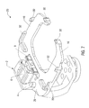
- FIG. 1 illustrates one embodiment of a shuttle apparatus.
- FIG. 2 illustrates an embodiment of the invention showing both a shuttle apparatus and a mating support structure.
- FIG. 3 illustrates an embodiment with the shuttle apparatus connected to a motorized ball screw and rotary device.
- FIG. 4 illustrates an embodiment of a pneumatically-actuated arm.
- FIG. 5 is a schematic of a shuttle apparatus positioned between two stackers.
- FIG. 6 illustrates an embodiment of an improved shuttle apparatus conveyor system.
- FIG. 7 illustrates an embodiment of the invention showing a gripper apparatus.
- FIG. 1 shows one embodiment of the shuttle apparatus 20 comprising a shuttle arm 24 and a shuttle table 28 .
- the shuttle arm 24 lies in a vertical plane
- the shuttle table 28 lies in a horizontal plane, with the shuttle arm 24 giving support to the shuttle table 28 .
- the shuttle table 28 has a top surface 16 and a bottom surface 18 .
- the top surface 16 of the shuttle table 28 having a mating section 10 .
- the top surface 16 of the shuttle table 28 has a series of boss structures 32 .
- the boss structures 32 are protuberances that rise from the top surface 16 of the shuttle table 28 .
- the boss structures 32 are incrementally placed along the edges of the shuttle table 28 .
- the boss structures 32 are chamfered.
- the chamfers 36 located on the surface of the boss structures 32 .
- the mating section 10 of the shuttle table 28 contains a void.
- This void section 40 is a C-shaped cutout of the shuttle table 28 .
- the open end 44 of the C-shaped cutout is located at the front end of the shuttle table 28 , which allows entrance into the void section 40 .
- FIG. 1 shows the shuttle apparatus 20 with a vacuum apparatus 48 on each side of the void section 40 .
- Each vacuum apparatus 48 is shown having two vacuum chucks 52 .
- Each vacuum chuck 52 is enclosed within a vacuum boss structure 56 .
- the vacuum boss structure 56 protects the vacuum chucks 52 .
- the vacuum boss structure 56 provides a flat surface to engage the underside of a sample carrier, thereby allowing the vacuum chucks 52 to pull a proper vacuum.
- the vacuum is pulled through a channel in the shuttle table 28 .
- the channel runs longitudinally from the vacuum apparatus 48 to an opening at the back of the shuttle table 28 .
- an individual channel services each vacuum apparatus 48 .
- FIG. 2 shows a shuttle apparatus 20 and a mating support structure 60 .
- the mating support structure 60 passes within the void section 40 of the mating section 10 .
- the shuttle apparatus 20 receives a sample carrier from the mating support structure 60 .
- the sample carrier contains the experimental samples that are to be processed or transferred between storage areas.
- a variety of carriers well known to one skilled in the art may be used for the sample carrier of the present invention. Suitable examples of carriers include but are not limited to microwell plates and pipette tip boxes.
- the mating support structure 60 operates in a vertical plane. When it is desired for the mating support structure 60 to retrieve a sample carrier, a raising means will raise the mating support structure 60 until the top surface of the mating support structure meets the bottom surface of the sample carrier. The mating support structure 60 will then lower itself and the sample carrier. As shown in FIG. 2, the mating support structure 60 will be aligned vertically with the void section 40 of the shuttle table 28 . The mating support structure will continue downward passing from the top side 16 of the shuttle table 28 , through the void section 40 , and exiting the bottom side 18 of the shuttle table 28 , thereby presenting the sample carrier to the shuttle apparatus 20 . The top surface 16 of the shuttle table 28 meeting the bottom surface of the sample carrier.
- the mating section 10 does not have a void section 40 .
- the mating support structure 60 has a void section, thereby allowing the shuttle table 28 to pass through the void section of the mating support structure 60 during presentation of the sample carrier.
- the boss structures 32 register the sample carrier. By engaging tightly with the sides of the sample carrier, the boss structures 32 secure the sample carrier to the shuttle apparatus 20 .
- chamfers 36 are manufactured onto the boss structures 32 , thereby beveling the surface of the boss structures 32 .
- the sloped surface of the chamfers 36 allow a misaligned sample carrier to slide along the surface of the chamfers 36 and engage with the boss structures 32 , thereby accounting for the misalignment.
- the vacuum chucks 64 of the mating support structure 60 are turned off.
- the sample carrier disengages from the mating support structure 60 as it passes through the void section 40 .
- the vacuum apparatus 48 of the shuttle apparatus 20 is engaged, thereby firmly securing the sample carrier.
- a vacuum valve controls the vacuum pulled through the vacuum apparatus 48 .
- a vacuum sensor can be located with the vacuum valve. The vacuum sensor senses whether a vacuum is actually being pulled through the vacuum apparatus 48 , thereby determining if a sample carrier is present on the shuttle table 28 .
- a vacuum sensor can also be located on the mating support structure 60 .
- FIG. 3 shows the shuttle apparatus 20 attached to a rotary device 72 and a motorized ball screw 70 .
- the ball screw 70 is attached to a motor 68 , which is the motive force for the shuttle apparatus 20 .
- the ball screw 70 is threaded through a ball screw nut 76 , which is attached to a linear bearing block 78 .
- a linear bearing 74 is attached to the linear bearing block 78 .
- Also illustrated in FIG. 3 is a rotary device 72 . As shown, the rotary device 72 is attached to the shuttle arm 24 and a rotary table bridge 96 , which is fastened to the ball screw nut 76 .
- the rotary device 72 horizontally rotates the shuttle apparatus 20 , allowing access to the sample carrier from both sides.
- a variety of rotary devices well known to one skilled in the art can be used to rotate the shuttle apparatus 20 .
- Suitable examples of rotary devices useful for rotation include but are not limited to a pneumatic rotary actuator, an encoder/motor assembly, hydraulic rotac, and linear actuation of a linear-to-rotary linkage.
- the rotary device 72 will rotate the shuttle apparatus 20 one hundred and eighty degrees.
- the shuttle apparatus 20 is movable in a horizontal plane or a vertical plane. In the horizontal plane, the shuttle apparatus 20 is movable in either a linear direction or an angular direction. The shuttle apparatus 20 is further movable in both a vertical and a horizontal plane.
- a motive force will transfer the shuttle apparatus 20 between processing stations or storage areas. Many modes of transfer are well known to one skilled in the art. Appropriate modes of motive force for transferring the shuttle apparatus 20 include but are not limited to a motorized ball screw, rack and pinion, belt drive, chain drive, linear motor, pneumatic, and hydraulic.
- FIG. 3 illustrates one embodiment of the invention in which the rotary device 72 and shuttle apparatus 20 are shuttled by a motorized ball screw 70 .
- the motor 68 rotates the ball screw 70 , which twists within the threads of the ball screw nut 76 .
- the ball screw 70 twisting within the ball screw nut 76 causes the ball screw nut 76 to move, which in turn causes the attached linear bearing block 78 and rotary table bridge 96 to move. Movement of the rotary table bridge 96 in turn causes movement of the rotary device 72 and attached shuttle apparatus 20 .
- the linear bearing block 78 moves along the linear bearing 74 , thereby causing the shuttle apparatus 20 to move in a linearly horizontal direction.
- FIG. 4 depicts a pneumatically-actuated arm 80 .
- the pneumatically-actuated arm 80 comprises a pneumatic actuator 82 , an arm 84 , a base 86 , and multiple vacuum cups 88 .
- the base 86 provides support for the arm 84 and pneumatic actuator 82 .
- the arm 84 is connected to the pneumatic actuator 82 at one end, with the other end hanging free. Vacuum cups 88 are located on the end of the arm 84 that is hanging free.
- the pneumatic actuator 82 provides the raising means for moving the arm 84 up and down.
- the sample carrier When the sample carrier is transferred by the shuttle apparatus 20 , only the bottom side of the sample carrier is engaged by the shuttle apparatus 20 , thereby allowing the sample carrier to be transferred with or without a lid.
- the lid can be removed by a variety of means. For example, a lid can be removed by grippers grasping the sides or corners of the lid.
- An embodiment of the present invention implements the pneumatically-actuated arm 80 to remove the lid by engaging only the top of the lid.
- the pneumatically-actuated arm 80 is a separate structure from the shuttle apparatus 20 .
- the shuttle apparatus 20 transfers the sample carrier, the shuttle apparatus 20 passes underneath the cantilevered arm 84 of the pneumatically-actuated arm 80 .
- the arm 84 is horizontally stationary but moves in the vertical plane.
- the arm 84 will lower until the vacuum cups 88 engage the top of the sample carrier lid.
- a vacuum is pulled, thereby securing the lid to the vacuum cups 88 .
- the pneumatic actuator 82 will then lift the arm 84 with the lid, allowing the shuttle apparatus 20 to transfer the sample carrier without the lid.
- FIG. 5 illustrates a method of transferring a sample carrier between two stackers. As shown, a first stacker 90 and a second stacker 92 face each other. A process area 94 lies between the first stacker 90 and the second stacker 92 . The shuttle apparatus 20 transfers a sample carrier along a linear bearing 74 , which runs between the first stacker 90 and the second stacker 92 .
- the shuttle apparatus 20 will retrieve a sample carrier from the first stacker 90 .
- a motorized ball screw 70 will then move the shuttle apparatus 20 along a linear bearing 74 .
- a rotary device 72 will rotate the shuttle apparatus 20 one hundred eighty degrees, with the shuttle apparatus 20 still remaining in motion along the linear bearing 74 .
- the shuttle apparatus 20 will then be guided by the linear bearing 74 through a process area 94 .
- the shuttle apparatus 20 will continue moving along the linear bearing 74 until reaching the second stacker 92 .
- the shuttle apparatus 20 Upon reaching the second stacker 92 , the shuttle apparatus 20 will present the sample carrier to a mating support structure 60 of the second stacker 92 .
- the shuttle apparatus 20 can return the sample carrier to the first stacker 90 .
- FIG. 6 illustrates a method for an improved conveyor system.
- the method involves a series of shuttle apparatuses 20 .
- the series of shuttle apparatuses 20 are integrated with a series of mating support structures 60 .
- the mating support structures 60 are horizontally stationary but can move up or down.
- the shuttle apparatuses 20 are linearly or angularly movable in the horizontal direction.
- the shuttle apparatuses 20 transfer sample carriers between processing stations, incrementing each sample carrier from one processing station to the next processing station. Presentation of the sample carriers at each processing station is synchronized between the shuttle apparatuses 20 .
- the mating support structures 60 are horizontally stationary in a circular orientation.
- the shuttle apparatuses 20 incrementally transfer the sample carriers between the mating support structures 60 in a circular path, with the circular path of the shuttle apparatuses 20 concentric with the circular orientation of the mating support structures 60 .
- FIG. 7 illustrates another embodiment of the shuttle apparatus 20 , whereby the sample carrier is secured by a gripper apparatus 2 .
- the top surface 16 of the shuttle table 28 has a series of boss structures 32 and a gripper apparatus 2 .
- the gripper apparatus 2 comprises a gripper base 4 , which is attached to the shuttle table 28 .
- a pneumatic actuator 6 is attached to the gripper base 4 and a gripper arm 8 .
- the boss structures 32 When a sample carrier is presented to the mating section 10 of the shuttle table 28 , the boss structures 32 will engage the sample carrier. After the boss structures 32 engage the sample carrier, the pneumatic actuator 6 moves the gripper arm 8 horizontally across the top surface 16 of the shuttle table 28 . The gripper base 4 provides horizontal support to the pneumatic actuator 6 as it moves the gripper arm 8 . The gripper arm 8 will engage a side of the sample carrier, thereby firmly securing the sample carrier between the gripper arm 8 and the boss structures 32 .
Abstract
Description
Claims (14)
Priority Applications (3)
| Application Number | Priority Date | Filing Date | Title |
|---|---|---|---|
| US09/496,220 US6739448B1 (en) | 2000-02-01 | 2000-02-01 | Method and apparatus for shuttling microtitre plates |
| AU2001231273A AU2001231273A1 (en) | 2000-02-01 | 2001-02-01 | Method and apparatus for shuttling microtitre plates |
| PCT/US2001/003298 WO2001057538A1 (en) | 2000-02-01 | 2001-02-01 | Method and apparatus for shuttling microtitre plates |
Applications Claiming Priority (1)
| Application Number | Priority Date | Filing Date | Title |
|---|---|---|---|
| US09/496,220 US6739448B1 (en) | 2000-02-01 | 2000-02-01 | Method and apparatus for shuttling microtitre plates |
Publications (1)
| Publication Number | Publication Date |
|---|---|
| US6739448B1 true US6739448B1 (en) | 2004-05-25 |
Family
ID=23971722
Family Applications (1)
| Application Number | Title | Priority Date | Filing Date |
|---|---|---|---|
| US09/496,220 Expired - Fee Related US6739448B1 (en) | 2000-02-01 | 2000-02-01 | Method and apparatus for shuttling microtitre plates |
Country Status (3)
| Country | Link |
|---|---|
| US (1) | US6739448B1 (en) |
| AU (1) | AU2001231273A1 (en) |
| WO (1) | WO2001057538A1 (en) |
Cited By (5)
| Publication number | Priority date | Publication date | Assignee | Title |
|---|---|---|---|---|
| US20050115421A1 (en) * | 2003-12-01 | 2005-06-02 | Lyons Richard G. | Miniature fluid dispensing end-effector for geometrically constrained areas |
| US20080003084A1 (en) * | 2006-06-30 | 2008-01-03 | Behnke Merlin E | High speed tray transfer system |
| WO2013016035A1 (en) * | 2011-07-22 | 2013-01-31 | Constitution Medical, Inc. | Sample transport systems and methods |
| US20150300931A1 (en) * | 2012-11-01 | 2015-10-22 | Leica Biosystems Melbourne Pty Ltd | Slide transport system |
| EP3499241A1 (en) * | 2017-12-18 | 2019-06-19 | Tecan Trading Ag | Gripper with at least one vacuum cup |
Families Citing this family (5)
| Publication number | Priority date | Publication date | Assignee | Title |
|---|---|---|---|---|
| US6843962B2 (en) | 2001-09-06 | 2005-01-18 | Genetix Limited | Apparatus for and methods of handling biological sample containers |
| US6998094B2 (en) | 2001-09-06 | 2006-02-14 | Genetix Limited | Apparatus for and methods of handling biological sample containers |
| EP1496365B1 (en) | 2003-07-11 | 2014-06-04 | Tecan Trading AG | Device and method for transporting objects |
| DE102004021664A1 (en) * | 2004-05-03 | 2005-12-08 | H+P Labortechnik Ag | Microtitration plate shaker for e.g. pharmaceutical, chemical or biological research, has locators driven between working- and release positions |
| DE102006030068A1 (en) * | 2006-06-28 | 2008-01-03 | M2P-Labs Gmbh | Apparatus and method for the supply and removal of fluids in shaken microreactors arrays |
Citations (24)
| Publication number | Priority date | Publication date | Assignee | Title |
|---|---|---|---|---|
| US3934702A (en) | 1973-09-13 | 1976-01-27 | Chicago Display Company | Article transfer apparatus |
| US4077444A (en) | 1975-02-12 | 1978-03-07 | Gilson Warren E | Fraction collector |
| US4478094A (en) | 1983-01-21 | 1984-10-23 | Cetus Corporation | Liquid sample handling system |
| US4483927A (en) | 1980-04-18 | 1984-11-20 | Olympus Optical Co., Ltd. | Method of automatically analyzing chemical substances and an automatic chemical analyzer |
| US4558984A (en) * | 1984-05-18 | 1985-12-17 | Varian Associates, Inc. | Wafer lifting and holding apparatus |
| US4582990A (en) | 1980-10-27 | 1986-04-15 | Randam Electronics, Inc. | Analytical instrument with two moving trains of sample holder-carrying trays under microprocessor control |
| US4681742A (en) | 1984-10-01 | 1987-07-21 | Cetus Corporation | Assay tray |
| EP0292995A2 (en) | 1987-05-29 | 1988-11-30 | Sumitomo Electric Industries Limited | Cell passage device |
| EP0301583A2 (en) | 1987-07-31 | 1989-02-01 | Fujirebio Kabushiki Kaisha | Automatic immunological analysing apparatus |
| US5004399A (en) * | 1987-09-04 | 1991-04-02 | Texas Instruments Incorporated | Robot slice aligning end effector |
| US5102623A (en) | 1987-10-09 | 1992-04-07 | Seiko Instruments, Inc. | Infinitesimal liquid reactor |
| US5122342A (en) | 1988-07-16 | 1992-06-16 | Quatro Biosystems Limited | Bio-fluid assay apparatus |
| WO1992012233A1 (en) | 1991-01-11 | 1992-07-23 | Medical Research Council | Transfer of biological samples |
| US5203445A (en) * | 1990-03-17 | 1993-04-20 | Tokyo Electron Sagami Limited | Carrier conveying apparatus |
| US5226462A (en) | 1991-07-26 | 1993-07-13 | Carl Richard A | Introducing measured amounts of liquid into receptacles |
| US5245530A (en) | 1990-04-26 | 1993-09-14 | Hitachi, Ltd. | Method for forwarding automatically liquid samples, etc., and device for realizing same |
| US5309959A (en) | 1992-08-19 | 1994-05-10 | British Nuclear Fuels Plc | Dispensing apparatus |
| US5356525A (en) | 1993-04-16 | 1994-10-18 | Beckman Instruments, Inc. | Sample handling system |
| US5811306A (en) | 1995-09-04 | 1998-09-22 | Fuji Photo Film Co., Ltd. | Liquid spotting method |
| US5865224A (en) | 1996-12-20 | 1999-02-02 | Life Technologies, Inc. | Method and apparatus for automated dispensing |
| WO1999015905A1 (en) | 1997-09-24 | 1999-04-01 | Glaxo Group Limited | Systems and methods for handling and manipulating multi-well plates |
| US5988236A (en) | 1998-07-31 | 1999-11-23 | Gilson, Inc. | Multiple syringe pump assembly for liquid handler |
| US6063579A (en) | 1998-10-30 | 2000-05-16 | Incyte Pharmaceuticals, Inc. | Alignment mechanism |
| US6148878A (en) | 1999-10-04 | 2000-11-21 | Robodesign International, Inc. | Automated microplate filling device and method |
-
2000
- 2000-02-01 US US09/496,220 patent/US6739448B1/en not_active Expired - Fee Related
-
2001
- 2001-02-01 AU AU2001231273A patent/AU2001231273A1/en not_active Abandoned
- 2001-02-01 WO PCT/US2001/003298 patent/WO2001057538A1/en active Application Filing
Patent Citations (26)
| Publication number | Priority date | Publication date | Assignee | Title |
|---|---|---|---|---|
| US3934702A (en) | 1973-09-13 | 1976-01-27 | Chicago Display Company | Article transfer apparatus |
| US4077444A (en) | 1975-02-12 | 1978-03-07 | Gilson Warren E | Fraction collector |
| US4483927A (en) | 1980-04-18 | 1984-11-20 | Olympus Optical Co., Ltd. | Method of automatically analyzing chemical substances and an automatic chemical analyzer |
| US4582990A (en) | 1980-10-27 | 1986-04-15 | Randam Electronics, Inc. | Analytical instrument with two moving trains of sample holder-carrying trays under microprocessor control |
| US4478094A (en) | 1983-01-21 | 1984-10-23 | Cetus Corporation | Liquid sample handling system |
| US4478094B1 (en) | 1983-01-21 | 1988-04-19 | ||
| US4558984A (en) * | 1984-05-18 | 1985-12-17 | Varian Associates, Inc. | Wafer lifting and holding apparatus |
| US4681742A (en) | 1984-10-01 | 1987-07-21 | Cetus Corporation | Assay tray |
| EP0292995A2 (en) | 1987-05-29 | 1988-11-30 | Sumitomo Electric Industries Limited | Cell passage device |
| EP0301583A2 (en) | 1987-07-31 | 1989-02-01 | Fujirebio Kabushiki Kaisha | Automatic immunological analysing apparatus |
| US5004399A (en) * | 1987-09-04 | 1991-04-02 | Texas Instruments Incorporated | Robot slice aligning end effector |
| US5102623A (en) | 1987-10-09 | 1992-04-07 | Seiko Instruments, Inc. | Infinitesimal liquid reactor |
| US5122342A (en) | 1988-07-16 | 1992-06-16 | Quatro Biosystems Limited | Bio-fluid assay apparatus |
| EP0351988B1 (en) | 1988-07-16 | 1993-09-01 | Quatro Biosystems Limited | Bio-fluid assay apparatus |
| US5203445A (en) * | 1990-03-17 | 1993-04-20 | Tokyo Electron Sagami Limited | Carrier conveying apparatus |
| US5245530A (en) | 1990-04-26 | 1993-09-14 | Hitachi, Ltd. | Method for forwarding automatically liquid samples, etc., and device for realizing same |
| WO1992012233A1 (en) | 1991-01-11 | 1992-07-23 | Medical Research Council | Transfer of biological samples |
| US5226462A (en) | 1991-07-26 | 1993-07-13 | Carl Richard A | Introducing measured amounts of liquid into receptacles |
| US5309959A (en) | 1992-08-19 | 1994-05-10 | British Nuclear Fuels Plc | Dispensing apparatus |
| US5356525A (en) | 1993-04-16 | 1994-10-18 | Beckman Instruments, Inc. | Sample handling system |
| US5811306A (en) | 1995-09-04 | 1998-09-22 | Fuji Photo Film Co., Ltd. | Liquid spotting method |
| US5865224A (en) | 1996-12-20 | 1999-02-02 | Life Technologies, Inc. | Method and apparatus for automated dispensing |
| WO1999015905A1 (en) | 1997-09-24 | 1999-04-01 | Glaxo Group Limited | Systems and methods for handling and manipulating multi-well plates |
| US5988236A (en) | 1998-07-31 | 1999-11-23 | Gilson, Inc. | Multiple syringe pump assembly for liquid handler |
| US6063579A (en) | 1998-10-30 | 2000-05-16 | Incyte Pharmaceuticals, Inc. | Alignment mechanism |
| US6148878A (en) | 1999-10-04 | 2000-11-21 | Robodesign International, Inc. | Automated microplate filling device and method |
Non-Patent Citations (1)
| Title |
|---|
| CCS Packard, "Robotic Systems for Laboratory Automation", dated May 2, 2000. |
Cited By (14)
| Publication number | Priority date | Publication date | Assignee | Title |
|---|---|---|---|---|
| US20050115421A1 (en) * | 2003-12-01 | 2005-06-02 | Lyons Richard G. | Miniature fluid dispensing end-effector for geometrically constrained areas |
| US7131372B2 (en) * | 2003-12-01 | 2006-11-07 | Lockheed Martin Corporation | Miniature fluid dispensing end-effector for geometrically constrained areas |
| US20080003084A1 (en) * | 2006-06-30 | 2008-01-03 | Behnke Merlin E | High speed tray transfer system |
| WO2013016035A1 (en) * | 2011-07-22 | 2013-01-31 | Constitution Medical, Inc. | Sample transport systems and methods |
| AU2012287300B2 (en) * | 2011-07-22 | 2015-10-01 | Roche Diagnostics Hematology, Inc. | Sample transport systems and methods |
| US9435818B2 (en) | 2011-07-22 | 2016-09-06 | Roche Diagnostics Hematology, Inc. | Sample transport systems and methods |
| JP2015533417A (en) * | 2012-11-01 | 2015-11-24 | ライカ・バイオシステムズ・メルボルン・プロプライエタリー・リミテッドLeica Biosystems Melbourne Pty Ltd | Slide transport system |
| US20150300931A1 (en) * | 2012-11-01 | 2015-10-22 | Leica Biosystems Melbourne Pty Ltd | Slide transport system |
| US9927332B2 (en) * | 2012-11-01 | 2018-03-27 | Leica Biosystems Melbourne Pty Ltd | Slide transport system |
| EP3499241A1 (en) * | 2017-12-18 | 2019-06-19 | Tecan Trading Ag | Gripper with at least one vacuum cup |
| WO2019120700A1 (en) * | 2017-12-18 | 2019-06-27 | Tecan Trading Ag | Gripper |
| CN111448459A (en) * | 2017-12-18 | 2020-07-24 | 泰肯贸易股份公司 | Gripper |
| CN111448459B (en) * | 2017-12-18 | 2021-12-03 | 帝肯贸易股份公司 | Gripper |
| US11207693B2 (en) | 2017-12-18 | 2021-12-28 | Tecan Trading Ag | Gripper |
Also Published As
| Publication number | Publication date |
|---|---|
| WO2001057538A1 (en) | 2001-08-09 |
| AU2001231273A1 (en) | 2001-08-14 |
Similar Documents
| Publication | Publication Date | Title |
|---|---|---|
| US4892455A (en) | Wafer alignment and transport mechanism | |
| JP5226508B2 (en) | Shuttle type transfer device | |
| EP3196648B1 (en) | Device for lifting a sample tube | |
| US6739448B1 (en) | Method and apparatus for shuttling microtitre plates | |
| US4412771A (en) | Sample transport system | |
| JPS6329410B2 (en) | ||
| US6554561B2 (en) | Automated cell for handling parts received in parts carriers | |
| CN112171265B (en) | Sliding switch sliding cover assembly equipment and sliding switch assembly system | |
| US20060013730A1 (en) | Method and apparatus for handling labware within a storage device | |
| CN110606455A (en) | Automatic uncovering device for sample container | |
| US11860178B2 (en) | System and method for automatic closure of sample vessels | |
| CN207547056U (en) | A kind of heparin tube automatic sweep apparatus, test tube flat | |
| CN114334761B (en) | Automatic wafer transporter | |
| US20230176084A1 (en) | Gripper apparatus with reduced contamination risk | |
| GB2390158A (en) | Collecting imprinted cassettes or specimen slides | |
| KR102143715B1 (en) | Taping system and taping method | |
| JP2753200B2 (en) | Automatic opening device | |
| JP5276189B2 (en) | Microplate pickup device and microplate supply / recovery device | |
| JP3873983B2 (en) | Microplate feeder | |
| US20240125811A1 (en) | System and method for automatic closure of sample vessels | |
| CN112419597B (en) | Buckle closure mechanism and full-automatic beverage vending machine | |
| CN113325167B (en) | Automatic detection equipment | |
| JP2005249648A (en) | Feeder of microplate with lid | |
| US11846643B2 (en) | Test sample handling system with rotary carousel | |
| CN217060252U (en) | Sample sorting, transferring and storing device and sample assembly line analysis system |
Legal Events
| Date | Code | Title | Description |
|---|---|---|---|
| AS | Assignment |
Owner name: INCYTE PHARMACEUTICALS, INC., CALIFORNIA Free format text: ASSIGNMENT OF ASSIGNORS INTEREST;ASSIGNORS:BEVIRT, JOEBEN;BRINTON, GABRIEL NOAH;REEL/FRAME:010791/0951 Effective date: 20000411 |
|
| AS | Assignment |
Owner name: VELOCITY11, CALIFORNIA Free format text: ASSIGNMENT OF ASSIGNORS INTEREST;ASSIGNOR:INCYTE CORPORATION;REEL/FRAME:014506/0856 Effective date: 20040412 |
|
| REMI | Maintenance fee reminder mailed | ||
| FPAY | Fee payment |
Year of fee payment: 4 |
|
| SULP | Surcharge for late payment | ||
| AS | Assignment |
Owner name: AGILENT TECHNOLOGIES, INC.,COLORADO Free format text: MERGER;ASSIGNOR:VELOCITY11;REEL/FRAME:023646/0845 Effective date: 20091031 Owner name: AGILENT TECHNOLOGIES, INC., COLORADO Free format text: MERGER;ASSIGNOR:VELOCITY11;REEL/FRAME:023646/0845 Effective date: 20091031 |
|
| FPAY | Fee payment |
Year of fee payment: 8 |
|
| REMI | Maintenance fee reminder mailed | ||
| LAPS | Lapse for failure to pay maintenance fees | ||
| STCH | Information on status: patent discontinuation |
Free format text: PATENT EXPIRED DUE TO NONPAYMENT OF MAINTENANCE FEES UNDER 37 CFR 1.362 |
|
| FP | Expired due to failure to pay maintenance fee |
Effective date: 20160525 |