US6745449B2 - Method and apparatus for making a lid with an optically transmissive window - Google Patents
Method and apparatus for making a lid with an optically transmissive window Download PDFInfo
- Publication number
- US6745449B2 US6745449B2 US10/045,639 US4563901A US6745449B2 US 6745449 B2 US6745449 B2 US 6745449B2 US 4563901 A US4563901 A US 4563901A US 6745449 B2 US6745449 B2 US 6745449B2
- Authority
- US
- United States
- Prior art keywords
- windows
- plate
- window
- glass
- openings
- Prior art date
- Legal status (The legal status is an assumption and is not a legal conclusion. Google has not performed a legal analysis and makes no representation as to the accuracy of the status listed.)
- Expired - Fee Related, expires
Links
Images


Classifications
-
- G—PHYSICS
- G02—OPTICS
- G02B—OPTICAL ELEMENTS, SYSTEMS OR APPARATUS
- G02B26/00—Optical devices or arrangements for the control of light using movable or deformable optical elements
- G02B26/08—Optical devices or arrangements for the control of light using movable or deformable optical elements for controlling the direction of light
- G02B26/0816—Optical devices or arrangements for the control of light using movable or deformable optical elements for controlling the direction of light by means of one or more reflecting elements
- G02B26/0833—Optical devices or arrangements for the control of light using movable or deformable optical elements for controlling the direction of light by means of one or more reflecting elements the reflecting element being a micromechanical device, e.g. a MEMS mirror, DMD
- G02B26/0841—Optical devices or arrangements for the control of light using movable or deformable optical elements for controlling the direction of light by means of one or more reflecting elements the reflecting element being a micromechanical device, e.g. a MEMS mirror, DMD the reflecting element being moved or deformed by electrostatic means
-
- B—PERFORMING OPERATIONS; TRANSPORTING
- B24—GRINDING; POLISHING
- B24B—MACHINES, DEVICES, OR PROCESSES FOR GRINDING OR POLISHING; DRESSING OR CONDITIONING OF ABRADING SURFACES; FEEDING OF GRINDING, POLISHING, OR LAPPING AGENTS
- B24B7/00—Machines or devices designed for grinding plane surfaces on work, including polishing plane glass surfaces; Accessories therefor
- B24B7/10—Single-purpose machines or devices
- B24B7/16—Single-purpose machines or devices for grinding end-faces, e.g. of gauges, rollers, nuts, piston rings
- B24B7/17—Single-purpose machines or devices for grinding end-faces, e.g. of gauges, rollers, nuts, piston rings for simultaneously grinding opposite and parallel end faces, e.g. double disc grinders
-
- C—CHEMISTRY; METALLURGY
- C03—GLASS; MINERAL OR SLAG WOOL
- C03B—MANUFACTURE, SHAPING, OR SUPPLEMENTARY PROCESSES
- C03B33/00—Severing cooled glass
- C03B33/02—Cutting or splitting sheet glass or ribbons; Apparatus or machines therefor
- C03B33/04—Cutting or splitting in curves, especially for making spectacle lenses
-
- C—CHEMISTRY; METALLURGY
- C03—GLASS; MINERAL OR SLAG WOOL
- C03C—CHEMICAL COMPOSITION OF GLASSES, GLAZES OR VITREOUS ENAMELS; SURFACE TREATMENT OF GLASS; SURFACE TREATMENT OF FIBRES OR FILAMENTS MADE FROM GLASS, MINERALS OR SLAGS; JOINING GLASS TO GLASS OR OTHER MATERIALS
- C03C17/00—Surface treatment of glass, not in the form of fibres or filaments, by coating
- C03C17/06—Surface treatment of glass, not in the form of fibres or filaments, by coating with metals
- C03C17/09—Surface treatment of glass, not in the form of fibres or filaments, by coating with metals by deposition from the vapour phase
-
- C—CHEMISTRY; METALLURGY
- C03—GLASS; MINERAL OR SLAG WOOL
- C03C—CHEMICAL COMPOSITION OF GLASSES, GLAZES OR VITREOUS ENAMELS; SURFACE TREATMENT OF GLASS; SURFACE TREATMENT OF FIBRES OR FILAMENTS MADE FROM GLASS, MINERALS OR SLAGS; JOINING GLASS TO GLASS OR OTHER MATERIALS
- C03C27/00—Joining pieces of glass to pieces of other inorganic material; Joining glass to glass other than by fusing
- C03C27/02—Joining pieces of glass to pieces of other inorganic material; Joining glass to glass other than by fusing by fusing glass directly to metal
-
- G—PHYSICS
- G02—OPTICS
- G02B—OPTICAL ELEMENTS, SYSTEMS OR APPARATUS
- G02B6/00—Light guides; Structural details of arrangements comprising light guides and other optical elements, e.g. couplings
- G02B6/24—Coupling light guides
- G02B6/26—Optical coupling means
- G02B6/35—Optical coupling means having switching means
-
- C—CHEMISTRY; METALLURGY
- C03—GLASS; MINERAL OR SLAG WOOL
- C03C—CHEMICAL COMPOSITION OF GLASSES, GLAZES OR VITREOUS ENAMELS; SURFACE TREATMENT OF GLASS; SURFACE TREATMENT OF FIBRES OR FILAMENTS MADE FROM GLASS, MINERALS OR SLAGS; JOINING GLASS TO GLASS OR OTHER MATERIALS
- C03C2217/00—Coatings on glass
- C03C2217/20—Materials for coating a single layer on glass
- C03C2217/25—Metals
- C03C2217/257—Refractory metals
- C03C2217/26—Cr, Mo, W
-
- C—CHEMISTRY; METALLURGY
- C03—GLASS; MINERAL OR SLAG WOOL
- C03C—CHEMICAL COMPOSITION OF GLASSES, GLAZES OR VITREOUS ENAMELS; SURFACE TREATMENT OF GLASS; SURFACE TREATMENT OF FIBRES OR FILAMENTS MADE FROM GLASS, MINERALS OR SLAGS; JOINING GLASS TO GLASS OR OTHER MATERIALS
- C03C2218/00—Methods for coating glass
- C03C2218/10—Deposition methods
- C03C2218/15—Deposition methods from the vapour phase
- C03C2218/154—Deposition methods from the vapour phase by sputtering
-
- C—CHEMISTRY; METALLURGY
- C03—GLASS; MINERAL OR SLAG WOOL
- C03C—CHEMICAL COMPOSITION OF GLASSES, GLAZES OR VITREOUS ENAMELS; SURFACE TREATMENT OF GLASS; SURFACE TREATMENT OF FIBRES OR FILAMENTS MADE FROM GLASS, MINERALS OR SLAGS; JOINING GLASS TO GLASS OR OTHER MATERIALS
- C03C2218/00—Methods for coating glass
- C03C2218/30—Aspects of methods for coating glass not covered above
- C03C2218/32—After-treatment
- C03C2218/328—Partly or completely removing a coating
- C03C2218/33—Partly or completely removing a coating by etching
-
- Y—GENERAL TAGGING OF NEW TECHNOLOGICAL DEVELOPMENTS; GENERAL TAGGING OF CROSS-SECTIONAL TECHNOLOGIES SPANNING OVER SEVERAL SECTIONS OF THE IPC; TECHNICAL SUBJECTS COVERED BY FORMER USPC CROSS-REFERENCE ART COLLECTIONS [XRACs] AND DIGESTS
- Y02—TECHNOLOGIES OR APPLICATIONS FOR MITIGATION OR ADAPTATION AGAINST CLIMATE CHANGE
- Y02P—CLIMATE CHANGE MITIGATION TECHNOLOGIES IN THE PRODUCTION OR PROCESSING OF GOODS
- Y02P40/00—Technologies relating to the processing of minerals
- Y02P40/50—Glass production, e.g. reusing waste heat during processing or shaping
- Y02P40/57—Improving the yield, e-g- reduction of reject rates
-
- Y—GENERAL TAGGING OF NEW TECHNOLOGICAL DEVELOPMENTS; GENERAL TAGGING OF CROSS-SECTIONAL TECHNOLOGIES SPANNING OVER SEVERAL SECTIONS OF THE IPC; TECHNICAL SUBJECTS COVERED BY FORMER USPC CROSS-REFERENCE ART COLLECTIONS [XRACs] AND DIGESTS
- Y10—TECHNICAL SUBJECTS COVERED BY FORMER USPC
- Y10T—TECHNICAL SUBJECTS COVERED BY FORMER US CLASSIFICATION
- Y10T29/00—Metal working
- Y10T29/49—Method of mechanical manufacture
- Y10T29/49789—Obtaining plural product pieces from unitary workpiece
-
- Y—GENERAL TAGGING OF NEW TECHNOLOGICAL DEVELOPMENTS; GENERAL TAGGING OF CROSS-SECTIONAL TECHNOLOGIES SPANNING OVER SEVERAL SECTIONS OF THE IPC; TECHNICAL SUBJECTS COVERED BY FORMER USPC CROSS-REFERENCE ART COLLECTIONS [XRACs] AND DIGESTS
- Y10—TECHNICAL SUBJECTS COVERED BY FORMER USPC
- Y10T—TECHNICAL SUBJECTS COVERED BY FORMER US CLASSIFICATION
- Y10T29/00—Metal working
- Y10T29/49—Method of mechanical manufacture
- Y10T29/49826—Assembling or joining
- Y10T29/49885—Assembling or joining with coating before or during assembling
-
- Y—GENERAL TAGGING OF NEW TECHNOLOGICAL DEVELOPMENTS; GENERAL TAGGING OF CROSS-SECTIONAL TECHNOLOGIES SPANNING OVER SEVERAL SECTIONS OF THE IPC; TECHNICAL SUBJECTS COVERED BY FORMER USPC CROSS-REFERENCE ART COLLECTIONS [XRACs] AND DIGESTS
- Y10—TECHNICAL SUBJECTS COVERED BY FORMER USPC
- Y10T—TECHNICAL SUBJECTS COVERED BY FORMER US CLASSIFICATION
- Y10T29/00—Metal working
- Y10T29/49—Method of mechanical manufacture
- Y10T29/49995—Shaping one-piece blank by removing material
Definitions
- This invention relates in general to a lid having a frame which supports a window transmissive to radiation and, more particularly, to a method and apparatus for fabricating such a lid.
- An existing device includes a housing with an opening therein which is closed by a lid.
- the lid includes a frame, and a window which is disposed within and hermetically sealed to the frame, the window being transmissive to radiation in a waveband of interest.
- the device can be used in a television or a projector to form images, which are typically projected onto some type of screen so that they can be viewed by a person.
- the device includes within the housing a digital micromirror device (DMD) of a known type.
- DMD digital micromirror device
- This existing lid is made by forming a metal frame which has an opening through it, placing a piece of glass in the opening through the frame, and then heating the frame and glass until the peripheral edges of the glass become fused to the edges of the opening in the frame. The side surfaces of the glass are then ground and polished, and one or more coatings are applied to both sides of the glass. While this existing lid and the process of making it have been generally adequate for their intended purposes, they have not been satisfactory in all respects.
- each lid is of various different sizes, and/or glass windows of various different sizes. Fabricating each lid as a separate part is time-consuming and expensive, due in part to the separate handling and processing needed for each lid, and also due in part to the fact that separate tooling is needed for each different frame size, and the separate tooling is relatively expensive.
- grinding and polishing of the opposite side surfaces of the glass window in each separate frame requires a special support part capable of properly supporting a frame of that size within a double-disk grinding apparatus, and each such support part must be configured to conform to the particular size of the lid.
- a method is provided and involves: forming a plurality of windows which are each transmissive to radiation having a predetermined wavelength; fabricating a plate with a plurality of openings therethrough; fixedly securing each window to the plate in a manner so that an annular seal is provided between an annular portion of the window extending along a periphery thereof and an annular portion of the plate extending around the opening; simultaneously processing a respective surface on each of the windows secured to the plate; and thereafter cutting from the plate a plurality of sections which each include a respective one of the windows and a respective one of the annular portions of the plate.
- an apparatus includes: a plate having a plurality of openings therethrough; and a plurality of windows which are each transmissive to radiation having a predetermined wavelength, each window being secured to the plate in a manner providing an annular seal between an annular portion of the window extending along a periphery thereof and an annular portion of the plate extending around the opening, and each window having thereon a surface which needs to be processed.
- a method involves: heating a metal part in a wet hydrogen atmosphere; thereafter oxidizing a surface of the metal part; thereafter placing a glass part in contact with the surface of the metal part; and thereafter heating the metal part and the glass part to cause the glass part to become fused directly to the metal part.
- FIG. 1 is a diagrammatic sectional side view of an apparatus which includes a housing with an opening closed by a lid embodying the aspects of the present invention
- FIG. 2 is a diagrammatic exploded perspective view of the lid of FIG. 1;
- FIG. 3 is a diagrammatic sectional side view of a portion of the lid of FIG. 1;
- FIG. 4 is a flowchart showing a sequence of steps that are carried out to make glass windows in a method which embodies aspects of the present invention
- FIG. 5 is a diagrammatic perspective view of a glass window produced by the method of FIG. 4;
- FIG. 6 is a flowchart showing a sequence of steps that are carried out to make a metal plate in a method which embodies aspects of the present invention
- FIG. 7 is a diagrammatic bottom view of a metal plate produced by the method of FIG. 6;
- FIG. 8 is a diagrammatic top view of the metal plate of FIG. 7;
- FIG. 9 is a diagrammatic fragmentary sectional side view taken along the line 9 — 9 in FIG. 8;
- FIG. 10 is a flowchart showing a sequence of steps that are carried out to assemble various parts in a method which embodies aspects of the present invention.
- FIG. 11 is a diagrammatic top view of a lower fuse plate which is part of some tooling used during the method of FIG. 10;
- FIG. 12 is a diagrammatic sectional side view taken along the line 12 — 12 in FIG. 11;
- FIG. 13 is a diagrammatic top view of an upper fuse plate which is part of the tooling used during the method of FIG. 10;
- FIG. 14 is a diagrammatic sectional side view taken along the line 14 — 14 in FIG. 13;
- FIG. 15 is a diagrammatic perspective view of a counterweight which is part of the tooling used in the method of FIG. 10;
- FIG. 16 is a diagrammatic sectional side view of an assembly which exists at an interim stage of the method of FIG. 10;
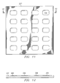
- FIG. 17 is a diagrammatic top view of a further assembly which exists at an interim stage of the method of FIG. 10 .
- FIG. 1 is a diagrammatic sectional side view of an apparatus 10 which embodies aspects of the present invention.
- the apparatus 10 includes a housing 11 which has a chamber 12 therein, and which has a top wall with a vertical opening 13 through it.
- a digital micromirror device (DMD) 16 of a known type is supported within the chamber 12 , in the center of the top surface of the bottom wall of the housing 11 .
- the DMD 16 has on an upper side thereof a two-dimensional array of tiny reflective mirrors. These mirrors each correspond to a respective pixel of an image, and can each be independently physically moved by the DMD 16 in response to electrical control signals.
- a lid 17 is provided on top of the housing 12 , so as to close the opening 13 in a manner effecting a hermetic seal between the interior and exterior of the housing 11 .
- the peripheral edges of the lid 17 are seam welded in a known manner to the top surface of the housing 11 .
- a gas is provided in the region 18 within the chamber 12 , and the lid 17 ensures that this gas does not escape from the region 18 in the chamber 12 .
- the gas serves to lubricate the mirrors of the two-dimensional array on the DMD 16 , in order to facilitate their movement, and to ensure that they have a relatively long operational lifetime.
- this gas is also somewhat corrosive, and the housing 11 and lid 17 are thus resistant to corrosive damage from the gas.
- FIG. 2 is a diagrammatic perspective exploded view of the lid 17 .
- the lid 17 includes an annular metal frame 23 , and a window 24 which is fixedly mounted within the frame.
- the frame 23 is made from a steel material, for example the type of material which is readily commercially available from a number of different vendors as ASTM-F15.
- the frame 23 is a plate-like element with parallel top and bottom surfaces, the outer edge of the frame 23 having an approximately rectangular shape.
- An opening 27 extends vertically through the center of the frame 23 .
- the opening 27 has a shape which is approximately rectangular, except that it has rounded corners.
- the frame 23 has in its upper side an annular groove or recess 29 of approximately rectangular cross section. This recess 29 extends along the entire peripheral edge of the frame, so as to define along the entire periphery of the frame an outwardly projecting annular flange 32 which has a generally uniform width and thickness.
- the window 24 is a plate-like element having parallel top and bottom surfaces, and has approximately the same thickness as the frame 23 .
- the outer edge of the window has the shape of a rectangle with rounded corners, and in fact the window 24 has approximately the same size and shape as the opening 27 through the frame 23 .
- the peripheral edge of the window 24 is fused directly to the material of the frame 23 along the entire length thereof, thereby defining an annular seal between the window 24 and frame 23 which extends completely around the window 24 . This is a hermetic seal, which helps to keep the corrosive gas within the region 18 in the chamber 12 of the housing 11 .
- the technique used to fuse the edges of the window 24 to the frame 23 is discussed in more detail later.
- the window 24 includes a layer 38 of a borosilicon glass material, which in the disclosed embodiment is commercially available as catalog number 7056 from Corning Incorporated of Danville, Va.
- This particular glass material is transmissive to radiation in a range which is centered at a wavelength at about 545 nm, and which extends from approximately 420 nm to about 700 nm. Further, this particular glass material has an index of refraction which is approximately 1.47 to 1.50 for radiation at the center wavelength of 545 nm.
- the window 24 has, on the underside of the glass layer 38 , a very thin layer 41 of an opaque material, which in the disclosed embodiment is chrome.
- a very thin layer 41 of an opaque material which in the disclosed embodiment is chrome.
- chrome for clarity the thickness of the chrome layer 41 is exaggerated in the drawings in relation to the sizes of other parts.
- a rectangular aperture 42 is provided through the center of the chrome layer 41 .
- the chrome layer 41 may optionally be omitted from the window 24 .
- the window 24 further includes, on both the top and bottom sides thereof, a very thin coating of an antireflective (AR) material.
- AR antireflective
- FIG. 3 is a diagrammatic fragmentary sectional side view of a small portion of the window 24 , and shows the glass layer 38 , the chrome layer 41 with the aperture 42 , and also the AR coatings at 46 and 47 .
- the thicknesses of the chrome layer 41 and the AR coatings 46 - 47 are all exaggerated in FIG. 3 .
- the AR coatings 46 and 47 are each transmissive to radiation within the above-mentioned range of approximately 420 nm to about 700 nm.
- the AR coatings 46 - 47 are both made from silicon dioxide. However, they could alternatively be made from some other suitable anti-reflective material, such as magnesium fluoride.
- the apparatus 10 operates as follows.
- a beam of inbound radiation which is represented diagrammatically by two arrows 56 in FIG. 1, passes through the window 24 and travels to the DMD 16 .
- Each of the mirrors of the DMD 16 reflects a respective portion of the beam in a respective direction determined by the current physical location of that mirror.
- the various independently reflected portions of the original beam are each referred to here as a sub-beam.
- the different sub-beams then travel away from the DMD 16 in various different directions, and at least some of them will travel back out through the window 24 , as indicated diagrammatically in FIG. 1 by two arrows 57 .
- the arrows representing the inbound radiation 56 and the outbound radiation 57 are shown as vertical lines in FIG. 1, but it will be recognized that various different beams and sub-beams would typically be traveling in various different directions. All of the radiation 56 - 57 passing in either direction through the window 24 must, of course, pass through the aperture 42 in the chrome layer 41 .
- FIG. 4 is a flowchart showing a portion of this method.
- FIG. 4 shows a sequence of steps which are carried out to make a plurality of glass elements that will each become a glass layer 38 within the window 24 of a respective lid 17 .
- block 101 in FIG. 4 indicates that raw glass material is shaped into a plate.
- the raw glass material used in the disclosed embodiment is a borosilicate glass material which is commercially available as catalog number 7056 from Corning Incorporated.
- a quantity of this raw glass material is heated for approximately 16 hours at a temperature which is increased progressively from an ambient room temperature of about 25° C. to a temperature of 1050° C.
- This heated glass material is then pressed and/or formed into a sheet having a uniform thickness of about 0.155 inches. This glass sheet is then gradually cooled back to 25° C.
- FIG. 5 is a diagrammatic perspective view showing one of these glass window elements at 106 .
- the glass window elements 106 are each cut from the glass sheet by machining or milling, or by using a laser.
- the peripheral edge of the glass window 106 has an approximately rectangular shape, with rounded corners, so that the element 106 has effectively the same size and shape as the opening 27 (FIG. 2) in one of the frames 23 .
- the glass window 106 is at this point somewhat thicker than the glass layer shown at 38 in FIGS. 2 and 3, because a portion of the glass window 106 will be subsequently removed by grinding and polishing, as discussed later.
- FIG. 6 is a flowchart showing a sequence of steps which are carried out to make a metal plate having several sections that each correspond to the frame 23 of FIG. 2 .
- the sequence shown in FIG. 6 begins with a sheet of raw metal which, in the disclosed embodiment, is a steel material commercially available as ASTM-F15.
- this sheet of metal is subjected to fine-blanking, in order to create from it one or more square metal plates which, in the disclosed embodiment, each have a size of 7 inches by 7 inches.
- the fine-blanking process simultaneously creates a two-dimensional array of openings through each plate, where each opening is approximately rectangular but has rounded corners.
- FIG. 7 is a diagrammatic bottom view of a square metal plate 126 which is one of the 7 inch by 7 inch plates separated from the metal sheet by fine-blanking.
- the plate 126 has twenty of the approximately rectangular openings 127 extending through it. These openings 127 are arranged in an array having five rows and four columns.
- FIG. 8 is a diagrammatic top view of the plate 126 , showing the annular grooves 136 .
- FIG. 9 is a diagrammatic fragmentary sectional side view of a portion of the plate 126 , taken along the section line 9 — 9 in FIG. 8 .
- each of the annular grooves 136 extends around one of the respective openings 127 , in a manner so that the groove 136 is spaced outwardly a small distance from the opening 127 along the entire periphery of the opening 127 .
- Adjacent grooves 136 are spaced a small distance from each other, thereby defining a grid of perpendicular ribs 142 and 143 which each have the same vertical thickness as the plate 126 , and which serve to rigidify the central region of the plate 126 during subsequent processing.
- the plate 126 will eventually be cut up to form 20 frames which are each equivalent to the frame 23 (FIGS. 1 - 2 ), in a manner discussed in more detail later.
- the support rack with the plates thereon is immersed into a surfactant solution (soap solution) having a temperature of approximately 50° C. to 75° C., for a time interval in the range of approximately 5 minutes to 15 minutes.
- a surfactant solution having a temperature of approximately 50° C. to 75° C., for a time interval in the range of approximately 5 minutes to 15 minutes.
- the rack and plates are then removed from this solution.
- the rack and the plates are rinsed with de-ionized water at room temperature.
- the plates are etched by immersing the rack and plates into a room temperature ferric chloride solution for a time interval in the range of approximately 1 minute to 4 minutes. The rack and plates are then removed from this solution, and are allowed to drain. Then, at block 153 , the rack and plates are rinsed for 15 minutes with room temperature de-ionized water. Then, at block 156 , the rack and plates are dried at 150° C. for 20 minutes.
- the plates 126 are transferred from the rack to a ceramic support member, and are processed in a wet hydrogen furnace with a dew point setting of 15 to 30 PPM/° C. for a time interval in the range of approximately 11 to 15 minutes, while maintaining a peak temperature of approximately 950° C. to 1100° C.
- This serves to clean the metal plates by removing carbon, oxygen and sulfur impurities from the plates, along with other trapped contaminates, through the formation of products such as CH 4 , CO 2 and CO+H 2 .
- the plates and the ceramic support member could be subjected to a 3:1 disassociated ammonia atmosphere with a dew point setting of 20 to 40 PPM/° C. for a dwell time of 10 to 30 minutes, while maintaining a temperature of approximately 1000° C. to 1250° C.
- the method proceeds to block 158 , where the plates are transferred to a different ceramic support member.
- the plates are then oxidized by placing the plates and the ceramic support member in a wet nitrogen furnace for a time interval of approximately 9 to 13 minutes, while maintaining a peak temperature of approximately 600° C. to 1000° C.
- the layer of oxidation formed on the frames by this wet nitrogen process will have a thickness in the range of approximately 3 ⁇ to 10 ⁇ , and helps to increase the strength of the bond which will be formed between the glass and the metal. Too little oxidation or too much oxidation can serve to weaken the bond.
- FIG. 10 is a flowchart which shows a sequence of steps that are carried out in the disclosed embodiment in order to assemble the plate 126 (FIGS. 7-9) with 20 glass windows of the type shown at 106 (FIG. 5 ).
- a sample subset of the metal plates 126 is selected for inspection, and a sample subset of the glass windows 106 is selected for inspection.
- the inspection of frames and windows is carried out so as to obtain a 1% acceptable quality level (AQL), which is an industry standard technique where a table is used to determine the number of parts that need to be inspected in order to assure a specified quality level.
- AQL 1% acceptable quality level
- the following explanation of the assembly procedure deals with plates and windows which have passed the inspection procedure.
- each of the glass windows 106 is cleaned by etching it in a 49% hydrofluoric acid solution for 30 seconds to 2 minutes at 20° C. to 40° C. Then, each glass window 106 is rinsed in de-ionized water. Thereafter, each glass window 106 is baked until it is thoroughly dry, for example at a temperature of 150° C. for 20 minutes.
- FIG. 11 is a diagrammatic top view of a lower fuse plate 207 , which is part of the reusable fuse tooling provided for assembly.
- FIG. 12 is a diagrammatic sectional view of the lower fuse plate 207 , taken along the section line 12 — 12 in FIG. 11 .
- the plate 207 is made of a graphite material, has a size of 7 inches by 7 inches, and has in an upper side thereof a plurality of shallow recesses 208 .
- the recesses 208 are each approximately rectangular with rounded corners, so as to have approximately the same size and shape as the window elements 106 .
- FIG. 13 is a diagrammatic top view of an upper fuse plate 211 , which is a further part of the reusable fuse tooling.
- FIG. 14 is a diagrammatic sectional side view of the fuse plate 211 , taken along the line 14 — 14 in FIG. 13 .
- the fuse plate 211 is made of a graphite material, has a size of 7 inches by 7 inches, and has a plurality of openings 212 extending through it.
- Each of the openings 212 has an approximately rectangular shape with rounded corners, and the size and shape of the openings 212 correspond to the size and shape of the window elements 106 .
- FIG. 15 is a diagrammatic perspective view of a counterweight 216 , which is a further component of the reusable fuse tooling.
- the counterweight 216 is a plate-like element having parallel top and bottom surfaces, and having a peripheral edge which is shaped to be approximately rectangular with rounded corners.
- the counterweight is made of a graphite material, and the length and width of the counterweight 216 are slightly less than the length and width of each of the glass windows 106 .
- FIG. 16 is a diagrammatic sectional side view of an assembly 221 which includes the lower fuse plate 207 , the upper fuse plate 211 , the metal plate 126 , twenty of the glass windows 106 , and twenty of the counterweights 216 .
- twenty of the glass windows 106 are each placed on the lower fuse plate 207 so that a lower portion thereof is disposed in a respective one of the shallow recesses 208 .
- the metal plate 126 is then added, by moving it in a downward direction until it is rests on top of the lower fuse plate 207 .
- the twenty glass windows 106 will each be received within a respective opening 127 in the metal plate 126 .
- the glass windows 106 each have an initial thickness which is somewhat larger than the thickness of the metal plate 126 .
- the shallow recesses 208 each have a depth which is approximately half of the difference between the thickness of the glass windows 106 and the thickness of the metal plate 126 . Consequently, as evident from FIG. 16, the recesses 208 position the window elements 106 so that each window element 106 projects outwardly by approximately the same amount on each side of the plate 126 .
- the upper fuse plate 211 is added to the assembly, by moving it downwardly until it is resting on top of the metal plate 126 .
- the upper portion of each of the glass windows 106 is received within the lower portion of a respective opening 212 through the upper fuse plate 211 .
- a respective one of the counterweights 216 is placed on top of each of the glass windows 106 .
- the counterweights 216 serve to hold the glass windows 106 in place while the glass is being fused to the metal plate 126 , which occurs in a manner discussed below.
- the counterweights 216 are sized so that they have sufficient weight to hold the glass windows 106 in place, but without exerting so much force that the material of the glass windows 106 will tend to flow and deform when heated during the fusing process.
- the assembly 221 is placed in a furnace and fired in an inert atmosphere at a temperature of 900° C. to 1050° C.
- the assembly 221 is in the furnace for a time period from 1 hour and 45 minutes to 2 hours and 15 minutes, and is at the peak temperature for approximately 20 minutes.
- the material of the glass windows 106 softens, and the peripheral edge of each glass window 106 becomes directly fused to the edge of the associated opening 127 through the metal plate 126 , all along the circumference thereof.
- the assembly 221 is allowed to cool back to room temperature, so that the glass windows 106 harden again and become fixedly bonded to the metal plate 126 . This creates a hermetic seal between the glass windows 106 and the metal plate 126 along the entire peripheral edge of each of the glass windows 106 .
- the metal plate 126 and the glass windows 106 secured thereto are separated from the fusing tooling, including the counterweights 216 and the upper and lower fuse plates 207 and 211 . Due to the fact that the fuse plates 207 and 211 , and the counterweight 216 , are made from a graphite material, the glass material 106 does not tend to fuse to them during the fusing process, and it is thus not difficult to separate the metal plate 126 and glass windows 106 from the fuse tooling.
- each glass window 106 Due to the fact that the glass material of the windows 106 reaches a melting temperature and softens during the fusing process, the surfaces on opposite of each glass window 106 typically have their optical properties affected by the fusing process. Therefore, with reference to block 232 in FIG. 10, the opposite side surfaces of each glass window 106 are subjected to grinding and polishing.
- grinding and polishing are both used herein, because it is customary in the industry to use both terms. But it will be recognized that grinding and polishing both involve abrasive refinement of the surfaces of the windows 106 , and basically differ only in regard to the coarseness of the abrasive media which is utilized.
- both sides of all 20 glass windows 106 are ground and polished simultaneously.
- This is carried out through use of a not-illustrated double-disk grinding arrangement of a known type.
- double-disk grinding arrangement two abrasive and coaxial disks with diameters of about 24 inches are rotated relative to each other, and the metal plate 126 with the glass windows 106 secured therein is placed between two facing surfaces on the disks, so that the opposite sides of each glass window 106 each engage a respective surface on a respective disk.
- Both side surfaces of each of the glass windows 106 are then ground and polished simultaneously, until each side surface is approximately flush with either the top surface or the bottom surface of the metal plate 126 .
- the optical criteria are that both the top and bottom surfaces of each glass window 106 are polished to a flatness of four fringes spherical power and two fringes irregularity. Simultaneous grinding and polishing of both sides of all of the glass windows 106 provides a significant cost reduction over pre-existing techniques, where grinding and polishing are carried out on a single glass window mounted in a single metal frame.
- the assembly which includes the metal plate 126 with the windows 106 is subjected to processing which cleans the exposed surfaces of the metal plate 126 .
- the assembly which includes the metal plate 126 and the glass windows 106 is successively immersed in an acid descale bath, an alkaline clean bath, and a hydrochloric acid bath. These baths serve to clean the exposed surfaces of the metal plate 126 in preparation for plating, including removal of the oxidation which was formed on the metal in block 158 of FIG. 6 .
- the purpose of the oxidation was to provide a surface on the metal plate 126 which would ensure a secure bond between the metal plate 126 and the glass windows 106 .
- the exposed surfaces of the metal plate 126 are electroplated with a layer of nickel having a thickness of at least 200 microinches. Then, a layer of gold is electroplated onto the layer of nickel, the gold layer having a thickness of at least 50 microinches.
- the gold and nickel layers help to protect the ASTM-F15 steel material of the metal plate 126 from damage due to environmental factors, such as the corrosive characteristics of the lubricant gas which is disposed within the chamber 12 (FIG. 1) in the housing 11 .
- the thickness of the nickel and gold layers is verified by an x-ray fluorescence (XRF) measurement, using techniques which are known in the art.
- XRF x-ray fluorescence
- this XRF measurement is carried out on a subset of the assemblies that each include a metal plate 126 with windows 106 secured thereto.
- each of the glass windows 106 is cleaned on both sides. In the disclosed embodiment, this is carried out manually, using a lint-free cloth and isopropyl alcohol.
- the chrome layer 41 with the aperture 42 is optional. Consequently, at block 241 , a decision is made as to whether the chrome layer 41 is to be provided in the assembly which is currently being fabricated. If not, then the two subsequent blocks at 242 and 243 are skipped. Otherwise, the process proceeds to block 242 .
- a mask is used to apply a chrome layer to the lower side of each of the glass windows 106 .
- the mask is similar to the plate shown at 211 in FIGS. 13-14, except that the mask is made of metal and is significantly thinner than the plate 211 .
- the mask is placed over the bottom side of the metal plate 126 , so that the metal plate 126 is covered and only the bottom surfaces of the glass windows 106 are exposed.
- a layer of chrome is then sputtered onto the bottom surface of each of the glass windows 106 , with a thickness in the range of 700 ⁇ to 4,000 ⁇ .
- the mask is then removed.
- a layer of photoresist is applied over the bottom surfaces of the metal plate 126 and the glass windows 106 .
- This photoresist is patterned using known techniques, and then the chrome layer is etched so as to create in the chrome layer on each of the glass windows 106 a rectangular aperture, which corresponds to the aperture shown at 42 in the chrome layer 41 of FIGS. 1-2. The photoresist is then removed.
- a mask is used to apply an anti-reflective coating to both sides of each of the glass windows 106 .
- the mask used in block 146 is a thin metal mask which is physically equivalent to the metal mask discussed above in association with block 242 .
- the anti-reflective coating is applied to each side surface of each window 106 , but not to the gold-plated surfaces of the metal plate 126 .
- FIG. 17 is a diagrammatic top view of the assembly as it appears at this point in the fabrication process.
- the assembly of FIG. 17 includes the metal plate 126 , and the windows 106 secured in the openings 127 of the plate 126 .
- Reference numeral 251 denotes the chrome layer which is provided on and visible through one of the transparent windows 106
- reference numeral 252 designates the rectangular aperture through the chrome layer 251 .
- the anti-reflective coatings are present, but are not separately depicted in FIG. 17 .
- a not-illustrated sheet of plastic material is temporarily applied to each side of the assembly shown in FIG. 17, for example in the form of a sheet of static cling plastic material.
- the purpose of this plastic material is to protect the glass windows 106 while pieces are cut from the plate 126 .
- reference numeral 258 designates one of twenty rectangular broken lines, each of which represents a path along which a cut will be made through bottom wall of a respective groove 136 in the metal plate 126 .
- the rectangular broken lines 258 in FIG. 17 each extend around a respective one of the glass windows and around an associated portion of the metal plate 126 .
- a precision cut is made along each of the broken lines 258 , using a fine-blanking procedure of a known type.
- the cuts along the broken lines 258 could be made using a not-illustrated diamond wheel saw of a known type.
- the sheets of static cling plastic are removed from both sides of each of the twenty lids cut from the metal plate 126 . Then, both sides of each window in each of these lids is cleaned with a lint-free cloth and isopropyl alcohol. In the rare event there is any residue which resists removal by the isopropyl alcohol, acetone may optionally be used with a lint-free cloth to remove the residue. After cleaning, each lid is ready to be installed in an apparatus of the type shown at 10 in FIG. 1 .
- the present invention provides a number of technical advantages.
- One such technical advantage is that, because a number of steps during the fabrication process are each carried out so that a plurality of optical windows in a single assembly are processed simultaneously, the overall cost of the resulting lids can be significantly reduced, by 25% or more.
- the assembly can have a standard size such as 7 inches by 7 inches, regardless of the precise number of windows being processed.
- the 7 inch ⁇ 7 inch assembly can include a large number of windows when the windows are relatively small, or a smaller number of windows when the windows are relatively large.
- some specialized tooling may be needed for each configuration of the assembly, but certain other tooling can be standardized and used for all such assemblies having the standard size, regardless of the number of windows in any particular assembly.
- a single set of standardized tooling compatible with the 7 inch ⁇ 7 inch assembly size can be developed, and then used for all such assemblies, regardless of the specific number of windows in each assembly. Due to factors such as the significant cost of specialized tooling, standardization of the tooling can help to significantly reduce the overall costs of the resulting lids.
- a further advantage is that separate lids are not cut from each assembly until after almost all process steps have been completed, which also helps to effect a significant cost reduction. This is particularly true as to the steps of grinding and polishing the glass windows, applying and etching the optional chrome layers, and then applying anti-reflective coatings.
- Still another advantage is realized where a metal frame is subjected to a wet hydrogen process in order to remove impurities from the surface of the frame before it is oxidized and then fused to a glass window.
- the wet hydrogen process is significantly more effective at removing impurities than pre-existing techniques. Due to the fact that the wet hydrogen process is particularly effective in removing impurities, it results in a significant reduction in the formation of gases and thus the formation of bubbles within the glass windows. This in turn effects a significant reduction in the number of parts that must be discarded as defective, which represents a significant increase in the effective yield of the fabrication process, and thus a reduction in the cost of each part.
Abstract
Description
Claims (8)
Priority Applications (11)
| Application Number | Priority Date | Filing Date | Title |
|---|---|---|---|
| US10/045,639 US6745449B2 (en) | 2001-11-06 | 2001-11-06 | Method and apparatus for making a lid with an optically transmissive window |
| AU2002360352A AU2002360352A1 (en) | 2001-11-06 | 2002-11-06 | Method and apparatus for making a lid with an optically transmissive window |
| KR10-2004-7006846A KR20040071133A (en) | 2001-11-06 | 2002-11-06 | Method and apparatus for making a lid with an optically transmissive window |
| EP02795601A EP1446941B1 (en) | 2001-11-06 | 2002-11-06 | Method and apparatus for making a lid with an optically transmissive window |
| PCT/US2002/035754 WO2003041391A2 (en) | 2001-11-06 | 2002-11-06 | Method and apparatus for making a lid with an optically transmissive window |
| JP2003543302A JP2005512114A (en) | 2001-11-06 | 2002-11-06 | Method and apparatus for producing a lid with an optical transmission window |
| AT02795601T ATE381205T1 (en) | 2001-11-06 | 2002-11-06 | METHOD AND APPARATUS FOR PRODUCING A COVER CONTAINING AN OPTICALLY TRANSPARENT WINDOW |
| ES02795601T ES2300503T3 (en) | 2001-11-06 | 2002-11-06 | METHOD AND APPARATUS FOR MAKING A COVER WITH AN OPTICALLY TRANSMISSIVE WINDOW. |
| DE60224082T DE60224082T2 (en) | 2001-11-06 | 2002-11-06 | METHOD AND APPARATUS FOR PRODUCING A LID CONTAINING AN OPTICALLY TRANSLUCENT WINDOW |
| US10/862,275 US6908026B2 (en) | 2001-11-06 | 2004-06-07 | Method and apparatus for making a lid with an optically transmissive window |
| US10/862,263 US7098396B2 (en) | 2001-11-06 | 2004-06-07 | Method and apparatus for making a lid with an optically transmissive window |
Applications Claiming Priority (1)
| Application Number | Priority Date | Filing Date | Title |
|---|---|---|---|
| US10/045,639 US6745449B2 (en) | 2001-11-06 | 2001-11-06 | Method and apparatus for making a lid with an optically transmissive window |
Related Child Applications (2)
| Application Number | Title | Priority Date | Filing Date |
|---|---|---|---|
| US10/862,275 Division US6908026B2 (en) | 2001-11-06 | 2004-06-07 | Method and apparatus for making a lid with an optically transmissive window |
| US10/862,263 Division US7098396B2 (en) | 2001-11-06 | 2004-06-07 | Method and apparatus for making a lid with an optically transmissive window |
Publications (2)
| Publication Number | Publication Date |
|---|---|
| US20030101562A1 US20030101562A1 (en) | 2003-06-05 |
| US6745449B2 true US6745449B2 (en) | 2004-06-08 |
Family
ID=21939073
Family Applications (3)
| Application Number | Title | Priority Date | Filing Date |
|---|---|---|---|
| US10/045,639 Expired - Fee Related US6745449B2 (en) | 2001-11-06 | 2001-11-06 | Method and apparatus for making a lid with an optically transmissive window |
| US10/862,263 Expired - Lifetime US7098396B2 (en) | 2001-11-06 | 2004-06-07 | Method and apparatus for making a lid with an optically transmissive window |
| US10/862,275 Expired - Fee Related US6908026B2 (en) | 2001-11-06 | 2004-06-07 | Method and apparatus for making a lid with an optically transmissive window |
Family Applications After (2)
| Application Number | Title | Priority Date | Filing Date |
|---|---|---|---|
| US10/862,263 Expired - Lifetime US7098396B2 (en) | 2001-11-06 | 2004-06-07 | Method and apparatus for making a lid with an optically transmissive window |
| US10/862,275 Expired - Fee Related US6908026B2 (en) | 2001-11-06 | 2004-06-07 | Method and apparatus for making a lid with an optically transmissive window |
Country Status (9)
| Country | Link |
|---|---|
| US (3) | US6745449B2 (en) |
| EP (1) | EP1446941B1 (en) |
| JP (1) | JP2005512114A (en) |
| KR (1) | KR20040071133A (en) |
| AT (1) | ATE381205T1 (en) |
| AU (1) | AU2002360352A1 (en) |
| DE (1) | DE60224082T2 (en) |
| ES (1) | ES2300503T3 (en) |
| WO (1) | WO2003041391A2 (en) |
Cited By (10)
| Publication number | Priority date | Publication date | Assignee | Title |
|---|---|---|---|---|
| US20020192403A1 (en) * | 2001-06-13 | 2002-12-19 | Hanna Mark B. | Lid with window hermetically sealed to frame, and a method of making it |
| US20040217151A1 (en) * | 2001-11-06 | 2004-11-04 | Raytheon Company, A Delaware Corporation | Method and apparatus for making a lid with an optically transmissive window |
| US20050098472A1 (en) * | 2003-11-08 | 2005-05-12 | Lutz Rissing | Optoelectronic component assembly |
| US20050275930A1 (en) * | 2004-06-15 | 2005-12-15 | Satyadev Patel | Micromirror array assembly with in-array pillars |
| US6988338B1 (en) | 2002-10-10 | 2006-01-24 | Raytheon Company | Lid with a thermally protected window |
| US20060082858A1 (en) * | 2004-10-19 | 2006-04-20 | Peter Heureux | Micromirror array device and a method for making the same |
| US20060220199A1 (en) * | 2005-04-05 | 2006-10-05 | Duboc Robert M | Low cost hermetically sealed package |
| US20070004080A1 (en) * | 2005-06-30 | 2007-01-04 | Ouyang Mike X | Hermetic seals for micro-electromechanical system devices |
| US20070069356A1 (en) * | 2005-09-29 | 2007-03-29 | Shinko Electric Industries, Co., Ltd | Optical parts cap and method of manufacturing the same |
| US20080080077A1 (en) * | 2006-09-29 | 2008-04-03 | Texas Instruments Incorporated | Low cost window production for hermetically sealed optical packages |
Families Citing this family (12)
| Publication number | Priority date | Publication date | Assignee | Title |
|---|---|---|---|---|
| US7163838B2 (en) * | 2002-07-22 | 2007-01-16 | Texas Instruments Incorporated | Method and apparatus for forming a DMD window frame with molded glass |
| CA2520104A1 (en) * | 2003-03-24 | 2004-10-07 | Memphis Eye & Cataract Associates Ambulatory Surgery Center (D/B/A/ Meca Laser And Surgery Center) | Digital micromirror device having a window transparent to ultraviolet (uv) light |
| US7023605B2 (en) * | 2003-03-24 | 2006-04-04 | Memphis Eye & Cataract Associates Ambulatory Surgery Center | Digital micromirror device having a window transparent to ultraviolet (UV) light |
| US7161727B2 (en) * | 2003-03-24 | 2007-01-09 | Memphis Eye & Cataract Associates Ambulatory Surgery Center | Digital micromirror device having a window transparent to ultraviolet (UV) light |
| US7192197B2 (en) * | 2004-09-27 | 2007-03-20 | Neptec Optical Solutions, Inc. | Planetary cleaning motion optical connector cleaner |
| NL1030004C2 (en) * | 2005-09-21 | 2007-03-22 | Fico Singulation B V | Device and method for separating electronic components. |
| US7934435B2 (en) * | 2006-12-06 | 2011-05-03 | Corning Incorporated | Modular glass reference plate assembly |
| US8064122B2 (en) * | 2007-03-15 | 2011-11-22 | Asml Holding N.V. | Apertured window for enabling flexible illumination overfill of patterning devices |
| KR100866532B1 (en) | 2007-10-26 | 2008-11-03 | 주식회사 심텍 | Method of manufacturing board on chip semiconductor package substrate having ring-shaped plating line |
| US8031319B1 (en) | 2008-05-30 | 2011-10-04 | Raytheon Company | Hermetic liquid crystal cell and sealing technique |
| US9632345B2 (en) | 2012-05-24 | 2017-04-25 | Raytheon Company | Liquid crystal control structure, tip-tilt-focus optical phased array and high power adaptive optic |
| EP3004979B1 (en) | 2013-05-24 | 2019-01-16 | Raytheon Company | Adaptive-optics liquid-crystal array device having meander resistors |
Citations (13)
| Publication number | Priority date | Publication date | Assignee | Title |
|---|---|---|---|---|
| US4789228A (en) | 1983-10-21 | 1988-12-06 | Thomson-Csf | Electrically controlled optical switching device |
| US4988157A (en) | 1990-03-08 | 1991-01-29 | Bell Communications Research, Inc. | Optical switch using bubbles |
| US5061049A (en) * | 1984-08-31 | 1991-10-29 | Texas Instruments Incorporated | Spatial light modulator and method |
| US5095664A (en) * | 1990-01-30 | 1992-03-17 | Massachusetts Institute Of Technology | Optical surface polishing method |
| EP0542519A1 (en) | 1991-11-14 | 1993-05-19 | International Business Machines Corporation | Undercut membrane mask for high energy photon patterning |
| US5264393A (en) * | 1988-11-25 | 1993-11-23 | Fuji Photo Film Co., Ltd. | Solid state image pickup device and method of manufacturing the same |
| US5392155A (en) | 1988-06-17 | 1995-02-21 | Tamari; Vladimir F. | De-diffraction methods |
| US5650915A (en) * | 1994-05-25 | 1997-07-22 | Texas Instruments Incorporated | Thermally enhanced molded cavity package having a parallel lid |
| US5939785A (en) | 1996-04-12 | 1999-08-17 | Texas Instruments Incorporated | Micromechanical device including time-release passivant |
| US6072924A (en) | 1996-09-02 | 2000-06-06 | Nippon Telegraph And Telephone Corporation | Optical switch and method for assembling the same |
| US6154305A (en) | 1995-12-19 | 2000-11-28 | The Board Of Trustees Of The Leland Stanford Junior University | Miniature scanning confocal microscope |
| US20010053016A1 (en) * | 1999-12-28 | 2001-12-20 | Nelson William E. | Digital micromirror device and method for non-contacting, edge-coupled hidden hinge geometry |
| US6513214B2 (en) * | 1999-12-22 | 2003-02-04 | Matsushita Electric Works, Ltd. | Method of producing plural device chips from a thin plate of a pyroelectric material |
Family Cites Families (40)
| Publication number | Priority date | Publication date | Assignee | Title |
|---|---|---|---|---|
| US2065404A (en) * | 1934-07-19 | 1936-12-22 | Westinghouse Electric & Mfg Co | Glass-to-metal seal |
| US2708774A (en) | 1949-11-29 | 1955-05-24 | Rca Corp | Multiple glazed unit |
| US2768475A (en) | 1952-11-28 | 1956-10-30 | Rca Corp | Method of making glass-to-metal seal |
| US3632325A (en) * | 1969-06-11 | 1972-01-04 | Richland Glass Co Inc | Method of sealing glass to metal |
| US3670916A (en) | 1970-02-19 | 1972-06-20 | Arnold L Alpert | Food containerization |
| CA997419A (en) * | 1974-02-22 | 1976-09-21 | Her Majesty The Queen In Right Of Canada, As Represented By The Minister Of National Defence | Alkaline battery seal |
| JPS50116998A (en) * | 1974-02-28 | 1975-09-12 | ||
| US4135789A (en) | 1977-07-01 | 1979-01-23 | Beckman Instruments, Inc. | Seal for liquid crystal display |
| JPS58161950A (en) | 1982-03-17 | 1983-09-26 | Hitachi Ltd | Airtightly welded body and welding method thereof |
| JPS60192901A (en) * | 1984-03-14 | 1985-10-01 | Canon Inc | Array lens |
| JPS6136969A (en) | 1984-07-30 | 1986-02-21 | Nec Corp | Semiconductor solid-state image pickup device |
| GB2184475A (en) | 1985-12-16 | 1987-06-24 | Robert Mcdonald Richie | Glazing window frames |
| US4828905A (en) * | 1986-06-12 | 1989-05-09 | Sumitomo Special Metals Co., Ltd. | Magnetic recording medium |
| US4812420A (en) | 1986-09-30 | 1989-03-14 | Mitsubishi Denki Kabushiki Kaisha | Method of producing a semiconductor device having a light transparent window |
| JPH01164073A (en) | 1987-09-11 | 1989-06-28 | Canon Inc | Optoelectric conversion device |
| DE69006609T2 (en) | 1989-03-15 | 1994-06-30 | Ngk Insulators Ltd | Ceramic lid for closing a semiconductor element and method for closing a semiconductor element in a ceramic package. |
| DE9003394U1 (en) | 1990-03-23 | 1990-06-28 | Herberts Industrieglas Gmbh & Co. Kg, 5600 Wuppertal, De | |
| US5175611A (en) * | 1990-06-22 | 1992-12-29 | Watkins-Johnson Company | Microwave integrated circuit package to eliminate alumina substrate cracking |
| US5352892A (en) | 1992-05-29 | 1994-10-04 | Cornell Research Foundation, Inc. | Atmospheric pressure ion interface for a mass analyzer |
| US5293511A (en) | 1993-03-16 | 1994-03-08 | Texas Instruments Incorporated | Package for a semiconductor device |
| US5353852A (en) | 1993-09-16 | 1994-10-11 | Ryobi Motor Products Corporation | Depth of cut locking mechanism for a plunge-type router |
| JP3212199B2 (en) * | 1993-10-04 | 2001-09-25 | 旭硝子株式会社 | Flat cathode ray tube |
| US5408748A (en) * | 1994-09-19 | 1995-04-25 | Valley Engravers, Inc. | Method of making door frames |
| DE19502006A1 (en) | 1995-01-24 | 1996-08-01 | Heraeus Noblelight Gmbh | Optical component with vacuum-tight housing |
| US5510215A (en) | 1995-01-25 | 1996-04-23 | Eastman Kodak Company | Method for patterning multilayer dielectric color filter |
| US5832585A (en) * | 1996-08-13 | 1998-11-10 | National Semiconductor Corporation | Method of separating micro-devices formed on a substrate |
| US6195881B1 (en) * | 1997-10-08 | 2001-03-06 | The Erie Ceramic Arts Company | Multiple coated substrates |
| US6827449B1 (en) * | 1997-12-31 | 2004-12-07 | Texas Instruments Incorporated | Adhesive-sealed window lid for micromechanical devices |
| AU2024099A (en) | 1998-01-02 | 1999-07-26 | Ashland Inc. | Water repellent glass treatment for automotive applications |
| US6265076B1 (en) | 1998-02-06 | 2001-07-24 | Libbey-Owens-Ford Co. | Anti-reflective films |
| US6261867B1 (en) | 1998-03-13 | 2001-07-17 | Stratedge Corporation | Method of making a package for microelectronic devices using iron oxide as a bonding agent |
| KR100382065B1 (en) * | 1998-07-29 | 2003-07-18 | 삼성에스디아이 주식회사 | Lithium secondary battery |
| US6282262B1 (en) * | 1999-11-10 | 2001-08-28 | Varian Medical Systems, Inc. | X-ray tube and method of manufacture |
| JP4193322B2 (en) | 2000-03-31 | 2008-12-10 | 住友電気工業株式会社 | Lens and infrared sensor using the same |
| US6453556B1 (en) * | 2000-10-11 | 2002-09-24 | Hmy Ltd. | Method of producing exhaust gas vane blade for superchargers of motor vehicles and vane blade |
| US6393681B1 (en) * | 2001-01-19 | 2002-05-28 | Magnecomp Corp. | PZT microactuator processing |
| US6559539B2 (en) | 2001-01-24 | 2003-05-06 | Hsiu Wen Tu | Stacked package structure of image sensor |
| US6974517B2 (en) * | 2001-06-13 | 2005-12-13 | Raytheon Company | Lid with window hermetically sealed to frame, and a method of making it |
| US6745449B2 (en) | 2001-11-06 | 2004-06-08 | Raytheon Company | Method and apparatus for making a lid with an optically transmissive window |
| US6667837B1 (en) * | 2002-01-30 | 2003-12-23 | Raytheon Company | Method and apparatus for configuring an aperture edge |
-
2001
- 2001-11-06 US US10/045,639 patent/US6745449B2/en not_active Expired - Fee Related
-
2002
- 2002-11-06 KR KR10-2004-7006846A patent/KR20040071133A/en not_active Application Discontinuation
- 2002-11-06 AU AU2002360352A patent/AU2002360352A1/en not_active Abandoned
- 2002-11-06 ES ES02795601T patent/ES2300503T3/en not_active Expired - Lifetime
- 2002-11-06 AT AT02795601T patent/ATE381205T1/en not_active IP Right Cessation
- 2002-11-06 EP EP02795601A patent/EP1446941B1/en not_active Expired - Lifetime
- 2002-11-06 WO PCT/US2002/035754 patent/WO2003041391A2/en active IP Right Grant
- 2002-11-06 JP JP2003543302A patent/JP2005512114A/en active Pending
- 2002-11-06 DE DE60224082T patent/DE60224082T2/en not_active Expired - Lifetime
-
2004
- 2004-06-07 US US10/862,263 patent/US7098396B2/en not_active Expired - Lifetime
- 2004-06-07 US US10/862,275 patent/US6908026B2/en not_active Expired - Fee Related
Patent Citations (13)
| Publication number | Priority date | Publication date | Assignee | Title |
|---|---|---|---|---|
| US4789228A (en) | 1983-10-21 | 1988-12-06 | Thomson-Csf | Electrically controlled optical switching device |
| US5061049A (en) * | 1984-08-31 | 1991-10-29 | Texas Instruments Incorporated | Spatial light modulator and method |
| US5392155A (en) | 1988-06-17 | 1995-02-21 | Tamari; Vladimir F. | De-diffraction methods |
| US5264393A (en) * | 1988-11-25 | 1993-11-23 | Fuji Photo Film Co., Ltd. | Solid state image pickup device and method of manufacturing the same |
| US5095664A (en) * | 1990-01-30 | 1992-03-17 | Massachusetts Institute Of Technology | Optical surface polishing method |
| US4988157A (en) | 1990-03-08 | 1991-01-29 | Bell Communications Research, Inc. | Optical switch using bubbles |
| EP0542519A1 (en) | 1991-11-14 | 1993-05-19 | International Business Machines Corporation | Undercut membrane mask for high energy photon patterning |
| US5650915A (en) * | 1994-05-25 | 1997-07-22 | Texas Instruments Incorporated | Thermally enhanced molded cavity package having a parallel lid |
| US6154305A (en) | 1995-12-19 | 2000-11-28 | The Board Of Trustees Of The Leland Stanford Junior University | Miniature scanning confocal microscope |
| US5939785A (en) | 1996-04-12 | 1999-08-17 | Texas Instruments Incorporated | Micromechanical device including time-release passivant |
| US6072924A (en) | 1996-09-02 | 2000-06-06 | Nippon Telegraph And Telephone Corporation | Optical switch and method for assembling the same |
| US6513214B2 (en) * | 1999-12-22 | 2003-02-04 | Matsushita Electric Works, Ltd. | Method of producing plural device chips from a thin plate of a pyroelectric material |
| US20010053016A1 (en) * | 1999-12-28 | 2001-12-20 | Nelson William E. | Digital micromirror device and method for non-contacting, edge-coupled hidden hinge geometry |
Non-Patent Citations (2)
| Title |
|---|
| U.S. Ser. No. 09/938,692, filed Aug. 23, 2001, entitled "Method and Apparatus for Controlling Emission of Radiation from a Housing", by inventor Stephen Michael Shockey, 22 pages of text and 2 drawing sheets. |
| U.S. Ser. No. 10/066,139, filed Jan. 30, 2002, entitled "Method and Apparatus for Configuring an Aperture Edge", by inventor Stephen Michael Shockey, 24 pages of text and 2 drawing sheets. |
Cited By (27)
| Publication number | Priority date | Publication date | Assignee | Title |
|---|---|---|---|---|
| US6974517B2 (en) | 2001-06-13 | 2005-12-13 | Raytheon Company | Lid with window hermetically sealed to frame, and a method of making it |
| US20020192403A1 (en) * | 2001-06-13 | 2002-12-19 | Hanna Mark B. | Lid with window hermetically sealed to frame, and a method of making it |
| US7098396B2 (en) * | 2001-11-06 | 2006-08-29 | Raytheon Company | Method and apparatus for making a lid with an optically transmissive window |
| US20040217151A1 (en) * | 2001-11-06 | 2004-11-04 | Raytheon Company, A Delaware Corporation | Method and apparatus for making a lid with an optically transmissive window |
| US20040221525A1 (en) * | 2001-11-06 | 2004-11-11 | Raytheon Company | Method and apparatus for making a lid with an optically transmissive window |
| US6908026B2 (en) * | 2001-11-06 | 2005-06-21 | Raytheon Company | Method and apparatus for making a lid with an optically transmissive window |
| US6988338B1 (en) | 2002-10-10 | 2006-01-24 | Raytheon Company | Lid with a thermally protected window |
| US20050098472A1 (en) * | 2003-11-08 | 2005-05-12 | Lutz Rissing | Optoelectronic component assembly |
| US7518157B2 (en) * | 2003-11-08 | 2009-04-14 | Dr. Johannes Heidenhain Gmbh | Optoelectronic component assembly |
| US7787170B2 (en) | 2004-06-15 | 2010-08-31 | Texas Instruments Incorporated | Micromirror array assembly with in-array pillars |
| US8693082B2 (en) | 2004-06-15 | 2014-04-08 | Texas Instruments Incorporated | Micromirror array assembly with in-array pillars |
| US9261696B2 (en) | 2004-06-15 | 2016-02-16 | Texas Insturments Incorporated | Micromirror array assembly |
| US20100302618A1 (en) * | 2004-06-15 | 2010-12-02 | Texas Instruments Incorporated | Micromirror Array Assembly with In-Array Pillars |
| US20050275930A1 (en) * | 2004-06-15 | 2005-12-15 | Satyadev Patel | Micromirror array assembly with in-array pillars |
| US7092143B2 (en) | 2004-10-19 | 2006-08-15 | Reflectivity, Inc | Micromirror array device and a method for making the same |
| US20060082858A1 (en) * | 2004-10-19 | 2006-04-20 | Peter Heureux | Micromirror array device and a method for making the same |
| US20060220199A1 (en) * | 2005-04-05 | 2006-10-05 | Duboc Robert M | Low cost hermetically sealed package |
| US7508063B2 (en) | 2005-04-05 | 2009-03-24 | Texas Instruments Incorporated | Low cost hermetically sealed package |
| US20070004080A1 (en) * | 2005-06-30 | 2007-01-04 | Ouyang Mike X | Hermetic seals for micro-electromechanical system devices |
| US7348193B2 (en) | 2005-06-30 | 2008-03-25 | Corning Incorporated | Hermetic seals for micro-electromechanical system devices |
| US20070069356A1 (en) * | 2005-09-29 | 2007-03-29 | Shinko Electric Industries, Co., Ltd | Optical parts cap and method of manufacturing the same |
| US8042248B2 (en) * | 2006-09-29 | 2011-10-25 | Texas Instruments Incorporated | Low cost window production for hermetically sealed optical packages |
| US20120036695A1 (en) * | 2006-09-29 | 2012-02-16 | Texas Instruments Incorporated | Low cost window production for hermetically sealed optical packages |
| US9050764B2 (en) * | 2006-09-29 | 2015-06-09 | Texas Instruments Incorporated | Low cost window production for hermetically sealed optical packages |
| US20150205098A1 (en) * | 2006-09-29 | 2015-07-23 | Texas Instruments Incorporated | Low cost window production for hermetically sealed optical packages |
| US20080080077A1 (en) * | 2006-09-29 | 2008-04-03 | Texas Instruments Incorporated | Low cost window production for hermetically sealed optical packages |
| US9411159B2 (en) * | 2006-09-29 | 2016-08-09 | Texas Instruments Incorporated | Low cost window production for hermetically sealed optical packages |
Also Published As
| Publication number | Publication date |
|---|---|
| JP2005512114A (en) | 2005-04-28 |
| US6908026B2 (en) | 2005-06-21 |
| WO2003041391A3 (en) | 2003-10-30 |
| EP1446941B1 (en) | 2007-12-12 |
| DE60224082D1 (en) | 2008-01-24 |
| WO2003041391A2 (en) | 2003-05-15 |
| US7098396B2 (en) | 2006-08-29 |
| DE60224082T2 (en) | 2008-12-04 |
| EP1446941A2 (en) | 2004-08-18 |
| US20040221525A1 (en) | 2004-11-11 |
| AU2002360352A1 (en) | 2003-05-19 |
| ES2300503T3 (en) | 2008-06-16 |
| ATE381205T1 (en) | 2007-12-15 |
| US20040217151A1 (en) | 2004-11-04 |
| US20030101562A1 (en) | 2003-06-05 |
| KR20040071133A (en) | 2004-08-11 |
Similar Documents
| Publication | Publication Date | Title |
|---|---|---|
| US6745449B2 (en) | Method and apparatus for making a lid with an optically transmissive window | |
| US6795170B2 (en) | Structure for attaching a pellicle to a photo-mask | |
| US6974517B2 (en) | Lid with window hermetically sealed to frame, and a method of making it | |
| US5981392A (en) | Method of manufacturing semiconductor monocrystalline mirror-surface wafers which includes a gas phase etching process, and semiconductor monocrystalline mirror-surface wafers manufactured by the method | |
| US4405701A (en) | Methods of fabricating a photomask | |
| US8042248B2 (en) | Low cost window production for hermetically sealed optical packages | |
| KR20060106745A (en) | Mask blank glass substrate manufacturing method, mask blank manufacturing method, mask manufacturing method, mask blank glass substrate, mask blank, and mask | |
| US6988338B1 (en) | Lid with a thermally protected window | |
| JPH06269968A (en) | Method and device for cutting glass | |
| JP4650886B2 (en) | Manufacturing method of glass substrate for mask blanks and manufacturing method of mask blanks | |
| JP2007033857A (en) | Method for manufacturing glass substrate for mask blanks, glass substrate for mask blanks, method for manufacturing mask blanks, and mask blanks | |
| JP4803576B2 (en) | Mask blank substrate, mask blank, exposure mask, semiconductor device manufacturing method, and mask blank substrate manufacturing method | |
| JP3529062B2 (en) | Pellicle and reticle | |
| EP0068012B1 (en) | A photomask and method of fabricating same | |
| JP2005039155A (en) | Method of manufacturing semiconductor device and method of manufacturing semiconductor substrate used for the device | |
| JP3775745B2 (en) | Reticle | |
| CN110342830B (en) | Near infrared filter and method for manufacturing the same | |
| JP2002323751A (en) | Pellicle | |
| JPH02204345A (en) | Glass substrate | |
| US6357098B1 (en) | Methods and devices for positioning and bonding elements to substrates | |
| JP7067131B2 (en) | Imprint mold manufacturing substrate and imprint mold and imprint mold manufacturing substrate manufacturing method and imprint mold manufacturing method | |
| JP2010066619A (en) | Pellicle and method for manufacturing the same | |
| JP2007147672A (en) | Glass lens and its manufacturing method | |
| JP2000169158A (en) | Die for forming optical glass element | |
| JPH0976087A (en) | Laser beam machining method |
Legal Events
| Date | Code | Title | Description |
|---|---|---|---|
| AS | Assignment |
Owner name: RAYTHEON COMPANY, MASSACHUSETTS Free format text: ASSIGNMENT OF ASSIGNORS INTEREST;ASSIGNORS:HANNA, MARK B.;NIX, KYLE W.;REEL/FRAME:012690/0264 Effective date: 20011114 |
|
| CC | Certificate of correction | ||
| FPAY | Fee payment |
Year of fee payment: 4 |
|
| FPAY | Fee payment |
Year of fee payment: 8 |
|
| AS | Assignment |
Owner name: OL SECURITY LIMITED LIABILITY COMPANY, DELAWARE Free format text: ASSIGNMENT OF ASSIGNORS INTEREST;ASSIGNOR:RAYTHEON COMPANY;REEL/FRAME:029117/0335 Effective date: 20120730 |
|
| FEPP | Fee payment procedure |
Free format text: PAYOR NUMBER ASSIGNED (ORIGINAL EVENT CODE: ASPN); ENTITY STATUS OF PATENT OWNER: LARGE ENTITY |
|
| REMI | Maintenance fee reminder mailed | ||
| LAPS | Lapse for failure to pay maintenance fees | ||
| STCH | Information on status: patent discontinuation |
Free format text: PATENT EXPIRED DUE TO NONPAYMENT OF MAINTENANCE FEES UNDER 37 CFR 1.362 |
|
| FP | Lapsed due to failure to pay maintenance fee |
Effective date: 20160608 |
|
| AS | Assignment |
Owner name: INTELLECTUAL VENTURES ASSETS 186 LLC, DELAWARE Free format text: ASSIGNMENT OF ASSIGNORS INTEREST;ASSIGNOR:OL SECURITY LIMITED LIABILITY COMPANY;REEL/FRAME:062756/0114 Effective date: 20221222 |
|
| AS | Assignment |
Owner name: INTELLECTUAL VENTURES ASSETS 186 LLC, DELAWARE Free format text: SECURITY INTEREST;ASSIGNOR:MIND FUSION, LLC;REEL/FRAME:063295/0001 Effective date: 20230214 Owner name: INTELLECTUAL VENTURES ASSETS 191 LLC, DELAWARE Free format text: SECURITY INTEREST;ASSIGNOR:MIND FUSION, LLC;REEL/FRAME:063295/0001 Effective date: 20230214 |
|
| AS | Assignment |
Owner name: MIND FUSION, LLC, WASHINGTON Free format text: ASSIGNMENT OF ASSIGNORS INTEREST;ASSIGNOR:INTELLECTUAL VENTURES ASSETS 186 LLC;REEL/FRAME:064271/0001 Effective date: 20230214 |