US6784017B2 - Method of creating a high performance organic semiconductor device - Google Patents
Method of creating a high performance organic semiconductor device Download PDFInfo
- Publication number
- US6784017B2 US6784017B2 US10/218,141 US21814102A US6784017B2 US 6784017 B2 US6784017 B2 US 6784017B2 US 21814102 A US21814102 A US 21814102A US 6784017 B2 US6784017 B2 US 6784017B2
- Authority
- US
- United States
- Prior art keywords
- organic
- semiconductor device
- organic semiconductor
- substrate
- metal
- Prior art date
- Legal status (The legal status is an assumption and is not a legal conclusion. Google has not performed a legal analysis and makes no representation as to the accuracy of the status listed.)
- Expired - Fee Related
Links
- 238000000034 method Methods 0.000 title claims abstract description 125
- 239000004065 semiconductor Substances 0.000 title claims abstract description 89
- 239000011368 organic material Substances 0.000 claims abstract description 64
- 239000010949 copper Substances 0.000 claims abstract description 42
- RYGMFSIKBFXOCR-UHFFFAOYSA-N Copper Chemical compound [Cu] RYGMFSIKBFXOCR-UHFFFAOYSA-N 0.000 claims abstract description 27
- 229910052802 copper Inorganic materials 0.000 claims abstract description 26
- 239000007769 metal material Substances 0.000 claims abstract description 24
- 229910052782 aluminium Inorganic materials 0.000 claims abstract description 19
- XAGFODPZIPBFFR-UHFFFAOYSA-N aluminium Chemical compound [Al] XAGFODPZIPBFFR-UHFFFAOYSA-N 0.000 claims abstract description 19
- 238000010438 heat treatment Methods 0.000 claims abstract description 4
- 239000012044 organic layer Substances 0.000 claims description 59
- 239000000758 substrate Substances 0.000 claims description 59
- 229910052751 metal Inorganic materials 0.000 claims description 41
- 239000002184 metal Substances 0.000 claims description 40
- 239000000463 material Substances 0.000 claims description 33
- 230000006870 function Effects 0.000 claims description 19
- 239000010703 silicon Substances 0.000 claims description 17
- 229910052710 silicon Inorganic materials 0.000 claims description 17
- -1 polyethylene terephthalate Polymers 0.000 claims description 12
- XMWRBQBLMFGWIX-UHFFFAOYSA-N C60 fullerene Chemical compound C12=C3C(C4=C56)=C7C8=C5C5=C9C%10=C6C6=C4C1=C1C4=C6C6=C%10C%10=C9C9=C%11C5=C8C5=C8C7=C3C3=C7C2=C1C1=C2C4=C6C4=C%10C6=C9C9=C%11C5=C5C8=C3C3=C7C1=C1C2=C4C6=C2C9=C5C3=C12 XMWRBQBLMFGWIX-UHFFFAOYSA-N 0.000 claims description 11
- 239000010931 gold Substances 0.000 claims description 9
- PCHJSUWPFVWCPO-UHFFFAOYSA-N gold Chemical compound [Au] PCHJSUWPFVWCPO-UHFFFAOYSA-N 0.000 claims description 8
- 229910052737 gold Inorganic materials 0.000 claims description 8
- PXHVJJICTQNCMI-UHFFFAOYSA-N Nickel Chemical compound [Ni] PXHVJJICTQNCMI-UHFFFAOYSA-N 0.000 claims description 7
- 239000011575 calcium Substances 0.000 claims description 7
- 150000001875 compounds Chemical class 0.000 claims description 7
- 229910003472 fullerene Inorganic materials 0.000 claims description 7
- 239000007789 gas Substances 0.000 claims description 7
- BASFCYQUMIYNBI-UHFFFAOYSA-N platinum Chemical compound [Pt] BASFCYQUMIYNBI-UHFFFAOYSA-N 0.000 claims description 7
- OYPRJOBELJOOCE-UHFFFAOYSA-N Calcium Chemical compound [Ca] OYPRJOBELJOOCE-UHFFFAOYSA-N 0.000 claims description 6
- 229910052791 calcium Inorganic materials 0.000 claims description 6
- 239000011777 magnesium Substances 0.000 claims description 6
- 229920000139 polyethylene terephthalate Polymers 0.000 claims description 6
- 239000005020 polyethylene terephthalate Substances 0.000 claims description 6
- XEEYBQQBJWHFJM-UHFFFAOYSA-N Iron Chemical compound [Fe] XEEYBQQBJWHFJM-UHFFFAOYSA-N 0.000 claims description 5
- FYYHWMGAXLPEAU-UHFFFAOYSA-N Magnesium Chemical compound [Mg] FYYHWMGAXLPEAU-UHFFFAOYSA-N 0.000 claims description 5
- 238000001816 cooling Methods 0.000 claims description 5
- 239000011521 glass Substances 0.000 claims description 5
- 229910052749 magnesium Inorganic materials 0.000 claims description 5
- WHXSMMKQMYFTQS-UHFFFAOYSA-N Lithium Chemical compound [Li] WHXSMMKQMYFTQS-UHFFFAOYSA-N 0.000 claims description 4
- 239000004793 Polystyrene Substances 0.000 claims description 4
- ZLMJMSJWJFRBEC-UHFFFAOYSA-N Potassium Chemical compound [K] ZLMJMSJWJFRBEC-UHFFFAOYSA-N 0.000 claims description 4
- VYPSYNLAJGMNEJ-UHFFFAOYSA-N Silicium dioxide Chemical compound O=[Si]=O VYPSYNLAJGMNEJ-UHFFFAOYSA-N 0.000 claims description 4
- 239000011651 chromium Substances 0.000 claims description 4
- 229910052744 lithium Inorganic materials 0.000 claims description 4
- 239000000203 mixture Substances 0.000 claims description 4
- 229910052700 potassium Inorganic materials 0.000 claims description 4
- 239000011591 potassium Substances 0.000 claims description 4
- 239000011135 tin Substances 0.000 claims description 4
- 239000010936 titanium Substances 0.000 claims description 4
- VYZAMTAEIAYCRO-UHFFFAOYSA-N Chromium Chemical compound [Cr] VYZAMTAEIAYCRO-UHFFFAOYSA-N 0.000 claims description 3
- 239000004698 Polyethylene Substances 0.000 claims description 3
- BQCADISMDOOEFD-UHFFFAOYSA-N Silver Chemical compound [Ag] BQCADISMDOOEFD-UHFFFAOYSA-N 0.000 claims description 3
- ATJFFYVFTNAWJD-UHFFFAOYSA-N Tin Chemical compound [Sn] ATJFFYVFTNAWJD-UHFFFAOYSA-N 0.000 claims description 3
- RTAQQCXQSZGOHL-UHFFFAOYSA-N Titanium Chemical compound [Ti] RTAQQCXQSZGOHL-UHFFFAOYSA-N 0.000 claims description 3
- 229910052785 arsenic Inorganic materials 0.000 claims description 3
- RQNWIZPPADIBDY-UHFFFAOYSA-N arsenic atom Chemical compound [As] RQNWIZPPADIBDY-UHFFFAOYSA-N 0.000 claims description 3
- 229910052804 chromium Inorganic materials 0.000 claims description 3
- 229910017052 cobalt Inorganic materials 0.000 claims description 3
- 239000010941 cobalt Substances 0.000 claims description 3
- GUTLYIVDDKVIGB-UHFFFAOYSA-N cobalt atom Chemical compound [Co] GUTLYIVDDKVIGB-UHFFFAOYSA-N 0.000 claims description 3
- 238000000151 deposition Methods 0.000 claims description 3
- 229910052738 indium Inorganic materials 0.000 claims description 3
- APFVFJFRJDLVQX-UHFFFAOYSA-N indium atom Chemical compound [In] APFVFJFRJDLVQX-UHFFFAOYSA-N 0.000 claims description 3
- 230000008018 melting Effects 0.000 claims description 3
- 238000002844 melting Methods 0.000 claims description 3
- 229910052759 nickel Inorganic materials 0.000 claims description 3
- 229910052697 platinum Inorganic materials 0.000 claims description 3
- 229920000573 polyethylene Polymers 0.000 claims description 3
- 229920002223 polystyrene Polymers 0.000 claims description 3
- 229910052814 silicon oxide Inorganic materials 0.000 claims description 3
- 229910052709 silver Inorganic materials 0.000 claims description 3
- 239000004332 silver Substances 0.000 claims description 3
- 239000010935 stainless steel Substances 0.000 claims description 3
- 229910001220 stainless steel Inorganic materials 0.000 claims description 3
- 229910052718 tin Inorganic materials 0.000 claims description 3
- 229910052719 titanium Inorganic materials 0.000 claims description 3
- WFKWXMTUELFFGS-UHFFFAOYSA-N tungsten Chemical compound [W] WFKWXMTUELFFGS-UHFFFAOYSA-N 0.000 claims description 3
- 229910052721 tungsten Inorganic materials 0.000 claims description 3
- 239000010937 tungsten Substances 0.000 claims description 3
- 229920006362 Teflon® Polymers 0.000 claims description 2
- 229910045601 alloy Inorganic materials 0.000 claims description 2
- 239000000956 alloy Substances 0.000 claims description 2
- 239000011248 coating agent Substances 0.000 claims description 2
- 238000000576 coating method Methods 0.000 claims description 2
- 238000002425 crystallisation Methods 0.000 claims description 2
- 230000008025 crystallization Effects 0.000 claims description 2
- 229920003223 poly(pyromellitimide-1,4-diphenyl ether) Polymers 0.000 claims description 2
- 229920006254 polymer film Polymers 0.000 claims description 2
- 229920001343 polytetrafluoroethylene Polymers 0.000 claims description 2
- 239000004810 polytetrafluoroethylene Substances 0.000 claims description 2
- IJGRMHOSHXDMSA-UHFFFAOYSA-N Atomic nitrogen Chemical compound N#N IJGRMHOSHXDMSA-UHFFFAOYSA-N 0.000 claims 2
- HCHKCACWOHOZIP-UHFFFAOYSA-N Zinc Chemical compound [Zn] HCHKCACWOHOZIP-UHFFFAOYSA-N 0.000 claims 2
- 229910052742 iron Inorganic materials 0.000 claims 2
- 229910052725 zinc Inorganic materials 0.000 claims 2
- 239000011701 zinc Substances 0.000 claims 2
- 239000004809 Teflon Substances 0.000 claims 1
- QVGXLLKOCUKJST-UHFFFAOYSA-N atomic oxygen Chemical compound [O] QVGXLLKOCUKJST-UHFFFAOYSA-N 0.000 claims 1
- 239000003302 ferromagnetic material Substances 0.000 claims 1
- 229910052757 nitrogen Inorganic materials 0.000 claims 1
- 239000001301 oxygen Substances 0.000 claims 1
- 229910052760 oxygen Inorganic materials 0.000 claims 1
- 230000008569 process Effects 0.000 abstract description 57
- 238000000137 annealing Methods 0.000 abstract description 17
- 238000002347 injection Methods 0.000 abstract description 11
- 239000007924 injection Substances 0.000 abstract description 11
- 229910052799 carbon Inorganic materials 0.000 abstract description 6
- 230000005669 field effect Effects 0.000 abstract description 4
- 230000005670 electromagnetic radiation Effects 0.000 abstract description 3
- 229910021645 metal ion Inorganic materials 0.000 abstract description 2
- 229920000642 polymer Polymers 0.000 description 22
- XUIMIQQOPSSXEZ-UHFFFAOYSA-N Silicon Chemical compound [Si] XUIMIQQOPSSXEZ-UHFFFAOYSA-N 0.000 description 15
- 239000010410 layer Substances 0.000 description 14
- 239000004020 conductor Substances 0.000 description 12
- 239000012212 insulator Substances 0.000 description 11
- 230000037230 mobility Effects 0.000 description 9
- 230000004888 barrier function Effects 0.000 description 8
- 230000008901 benefit Effects 0.000 description 7
- 238000010586 diagram Methods 0.000 description 7
- 150000002739 metals Chemical class 0.000 description 7
- 239000007772 electrode material Substances 0.000 description 5
- 239000002071 nanotube Substances 0.000 description 5
- 230000004044 response Effects 0.000 description 5
- 239000000126 substance Substances 0.000 description 5
- OKTJSMMVPCPJKN-UHFFFAOYSA-N Carbon Chemical compound [C] OKTJSMMVPCPJKN-UHFFFAOYSA-N 0.000 description 4
- 238000009792 diffusion process Methods 0.000 description 4
- 239000010408 film Substances 0.000 description 4
- 238000007641 inkjet printing Methods 0.000 description 4
- 150000002500 ions Chemical class 0.000 description 4
- 229920000265 Polyparaphenylene Polymers 0.000 description 3
- 230000009471 action Effects 0.000 description 3
- 230000006399 behavior Effects 0.000 description 3
- 230000015572 biosynthetic process Effects 0.000 description 3
- 238000005137 deposition process Methods 0.000 description 3
- 238000001704 evaporation Methods 0.000 description 3
- 238000004519 manufacturing process Methods 0.000 description 3
- 230000005012 migration Effects 0.000 description 3
- 238000013508 migration Methods 0.000 description 3
- 230000003287 optical effect Effects 0.000 description 3
- 239000010409 thin film Substances 0.000 description 3
- YMWLPMGFZYFLRP-UHFFFAOYSA-N 2-(4,5-dimethyl-1,3-diselenol-2-ylidene)-4,5-dimethyl-1,3-diselenole Chemical compound [Se]1C(C)=C(C)[Se]C1=C1[Se]C(C)=C(C)[Se]1 YMWLPMGFZYFLRP-UHFFFAOYSA-N 0.000 description 2
- YAHVGMRXXZDSOK-UHFFFAOYSA-N 5-([1,3]dithiolo[4,5-d][1,3]dithiol-5-ylidene)-[1,3]dithiolo[4,5-d][1,3]dithiole Chemical compound S1CSC(S2)=C1SC2=C(S1)SC2=C1SCS2 YAHVGMRXXZDSOK-UHFFFAOYSA-N 0.000 description 2
- 229920001609 Poly(3,4-ethylenedioxythiophene) Polymers 0.000 description 2
- 239000004642 Polyimide Substances 0.000 description 2
- 238000004833 X-ray photoelectron spectroscopy Methods 0.000 description 2
- JFBZPFYRPYOZCQ-UHFFFAOYSA-N [Li].[Al] Chemical compound [Li].[Al] JFBZPFYRPYOZCQ-UHFFFAOYSA-N 0.000 description 2
- 239000002800 charge carrier Substances 0.000 description 2
- XCJYREBRNVKWGJ-UHFFFAOYSA-N copper(II) phthalocyanine Chemical compound [Cu+2].C12=CC=CC=C2C(N=C2[N-]C(C3=CC=CC=C32)=N2)=NC1=NC([C]1C=CC=CC1=1)=NC=1N=C1[C]3C=CC=CC3=C2[N-]1 XCJYREBRNVKWGJ-UHFFFAOYSA-N 0.000 description 2
- 230000000694 effects Effects 0.000 description 2
- 238000005401 electroluminescence Methods 0.000 description 2
- 238000005516 engineering process Methods 0.000 description 2
- 230000008020 evaporation Effects 0.000 description 2
- 238000002474 experimental method Methods 0.000 description 2
- 230000005294 ferromagnetic effect Effects 0.000 description 2
- 239000012530 fluid Substances 0.000 description 2
- 230000006872 improvement Effects 0.000 description 2
- AMGQUBHHOARCQH-UHFFFAOYSA-N indium;oxotin Chemical compound [In].[Sn]=O AMGQUBHHOARCQH-UHFFFAOYSA-N 0.000 description 2
- 229910001092 metal group alloy Inorganic materials 0.000 description 2
- 229910052755 nonmetal Inorganic materials 0.000 description 2
- 150000002843 nonmetals Chemical class 0.000 description 2
- 150000002894 organic compounds Chemical class 0.000 description 2
- 229920001721 polyimide Polymers 0.000 description 2
- 229920000128 polypyrrole Polymers 0.000 description 2
- 230000005855 radiation Effects 0.000 description 2
- 238000007614 solvation Methods 0.000 description 2
- 238000003860 storage Methods 0.000 description 2
- NLDYACGHTUPAQU-UHFFFAOYSA-N tetracyanoethylene Chemical compound N#CC(C#N)=C(C#N)C#N NLDYACGHTUPAQU-UHFFFAOYSA-N 0.000 description 2
- FHCPAXDKURNIOZ-UHFFFAOYSA-N tetrathiafulvalene Chemical compound S1C=CSC1=C1SC=CS1 FHCPAXDKURNIOZ-UHFFFAOYSA-N 0.000 description 2
- 238000012546 transfer Methods 0.000 description 2
- TVIVIEFSHFOWTE-UHFFFAOYSA-K tri(quinolin-8-yloxy)alumane Chemical compound [Al+3].C1=CN=C2C([O-])=CC=CC2=C1.C1=CN=C2C([O-])=CC=CC2=C1.C1=CN=C2C([O-])=CC=CC2=C1 TVIVIEFSHFOWTE-UHFFFAOYSA-K 0.000 description 2
- 238000004402 ultra-violet photoelectron spectroscopy Methods 0.000 description 2
- UHXOHPVVEHBKKT-UHFFFAOYSA-N 1-(2,2-diphenylethenyl)-4-[4-(2,2-diphenylethenyl)phenyl]benzene Chemical compound C=1C=C(C=2C=CC(C=C(C=3C=CC=CC=3)C=3C=CC=CC=3)=CC=2)C=CC=1C=C(C=1C=CC=CC=1)C1=CC=CC=C1 UHXOHPVVEHBKKT-UHFFFAOYSA-N 0.000 description 1
- FQJQNLKWTRGIEB-UHFFFAOYSA-N 2-(4-tert-butylphenyl)-5-[3-[5-(4-tert-butylphenyl)-1,3,4-oxadiazol-2-yl]phenyl]-1,3,4-oxadiazole Chemical compound C1=CC(C(C)(C)C)=CC=C1C1=NN=C(C=2C=C(C=CC=2)C=2OC(=NN=2)C=2C=CC(=CC=2)C(C)(C)C)O1 FQJQNLKWTRGIEB-UHFFFAOYSA-N 0.000 description 1
- LZJCVNLYDXCIBG-UHFFFAOYSA-N 2-(5,6-dihydro-[1,3]dithiolo[4,5-b][1,4]dithiin-2-ylidene)-5,6-dihydro-[1,3]dithiolo[4,5-b][1,4]dithiine Chemical compound S1C(SCCS2)=C2SC1=C(S1)SC2=C1SCCS2 LZJCVNLYDXCIBG-UHFFFAOYSA-N 0.000 description 1
- JLTPSDHKZGWXTD-UHFFFAOYSA-N 2-[6-(dicyanomethylidene)naphthalen-2-ylidene]propanedinitrile Chemical compound N#CC(C#N)=C1C=CC2=CC(=C(C#N)C#N)C=CC2=C1 JLTPSDHKZGWXTD-UHFFFAOYSA-N 0.000 description 1
- 102100025683 Alkaline phosphatase, tissue-nonspecific isozyme Human genes 0.000 description 1
- 101710161969 Alkaline phosphatase, tissue-nonspecific isozyme Proteins 0.000 description 1
- NLZUEZXRPGMBCV-UHFFFAOYSA-N Butylhydroxytoluene Chemical compound CC1=CC(C(C)(C)C)=C(O)C(C(C)(C)C)=C1 NLZUEZXRPGMBCV-UHFFFAOYSA-N 0.000 description 1
- YTPLMLYBLZKORZ-UHFFFAOYSA-N Divinylene sulfide Natural products C=1C=CSC=1 YTPLMLYBLZKORZ-UHFFFAOYSA-N 0.000 description 1
- 101000679365 Homo sapiens Putative tyrosine-protein phosphatase TPTE Proteins 0.000 description 1
- 102100022578 Putative tyrosine-protein phosphatase TPTE Human genes 0.000 description 1
- 238000002441 X-ray diffraction Methods 0.000 description 1
- 229920000109 alkoxy-substituted poly(p-phenylene vinylene) Polymers 0.000 description 1
- HSFWRNGVRCDJHI-UHFFFAOYSA-N alpha-acetylene Natural products C#C HSFWRNGVRCDJHI-UHFFFAOYSA-N 0.000 description 1
- 239000010405 anode material Substances 0.000 description 1
- XKRFYHLGVUSROY-UHFFFAOYSA-N argon Substances [Ar] XKRFYHLGVUSROY-UHFFFAOYSA-N 0.000 description 1
- 229910052786 argon Inorganic materials 0.000 description 1
- 239000003990 capacitor Substances 0.000 description 1
- 239000002041 carbon nanotube Substances 0.000 description 1
- 229910021393 carbon nanotube Inorganic materials 0.000 description 1
- 230000015556 catabolic process Effects 0.000 description 1
- 239000010406 cathode material Substances 0.000 description 1
- 229910010293 ceramic material Inorganic materials 0.000 description 1
- 230000008859 change Effects 0.000 description 1
- 238000010351 charge transfer process Methods 0.000 description 1
- 238000006243 chemical reaction Methods 0.000 description 1
- MPMSMUBQXQALQI-UHFFFAOYSA-N cobalt phthalocyanine Chemical compound [Co+2].C12=CC=CC=C2C(N=C2[N-]C(C3=CC=CC=C32)=N2)=NC1=NC([C]1C=CC=CC1=1)=NC=1N=C1[C]3C=CC=CC3=C2[N-]1 MPMSMUBQXQALQI-UHFFFAOYSA-N 0.000 description 1
- 230000000295 complement effect Effects 0.000 description 1
- 230000007812 deficiency Effects 0.000 description 1
- 238000006731 degradation reaction Methods 0.000 description 1
- 230000008021 deposition Effects 0.000 description 1
- 229910003460 diamond Inorganic materials 0.000 description 1
- 239000010432 diamond Substances 0.000 description 1
- 239000002019 doping agent Substances 0.000 description 1
- 238000004870 electrical engineering Methods 0.000 description 1
- 230000007613 environmental effect Effects 0.000 description 1
- 239000011888 foil Substances 0.000 description 1
- 230000005525 hole transport Effects 0.000 description 1
- 238000011065 in-situ storage Methods 0.000 description 1
- 238000005304 joining Methods 0.000 description 1
- 239000008204 material by function Substances 0.000 description 1
- 238000005259 measurement Methods 0.000 description 1
- 230000007246 mechanism Effects 0.000 description 1
- 230000015654 memory Effects 0.000 description 1
- 150000002736 metal compounds Chemical class 0.000 description 1
- 239000013212 metal-organic material Substances 0.000 description 1
- 238000012986 modification Methods 0.000 description 1
- 230000004048 modification Effects 0.000 description 1
- 230000000877 morphologic effect Effects 0.000 description 1
- 230000004660 morphological change Effects 0.000 description 1
- LVIYYTJTOKJJOC-UHFFFAOYSA-N nickel phthalocyanine Chemical compound [Ni+2].C12=CC=CC=C2C(N=C2[N-]C(C3=CC=CC=C32)=N2)=NC1=NC([C]1C=CC=CC1=1)=NC=1N=C1[C]3C=CC=CC3=C2[N-]1 LVIYYTJTOKJJOC-UHFFFAOYSA-N 0.000 description 1
- 230000003071 parasitic effect Effects 0.000 description 1
- 239000002245 particle Substances 0.000 description 1
- 125000002080 perylenyl group Chemical group C1(=CC=C2C=CC=C3C4=CC=CC5=CC=CC(C1=C23)=C45)* 0.000 description 1
- CSHWQDPOILHKBI-UHFFFAOYSA-N peryrene Natural products C1=CC(C2=CC=CC=3C2=C2C=CC=3)=C3C2=CC=CC3=C1 CSHWQDPOILHKBI-UHFFFAOYSA-N 0.000 description 1
- IEQIEDJGQAUEQZ-UHFFFAOYSA-N phthalocyanine Chemical compound N1C(N=C2C3=CC=CC=C3C(N=C3C4=CC=CC=C4C(=N4)N3)=N2)=C(C=CC=C2)C2=C1N=C1C2=CC=CC=C2C4=N1 IEQIEDJGQAUEQZ-UHFFFAOYSA-N 0.000 description 1
- 239000004033 plastic Substances 0.000 description 1
- 229920003023 plastic Polymers 0.000 description 1
- 229920002848 poly(3-alkoxythiophenes) Polymers 0.000 description 1
- 229920000553 poly(phenylenevinylene) Polymers 0.000 description 1
- 229920001197 polyacetylene Polymers 0.000 description 1
- 229920000767 polyaniline Polymers 0.000 description 1
- 229920000015 polydiacetylene Polymers 0.000 description 1
- 239000002861 polymer material Substances 0.000 description 1
- 229920000307 polymer substrate Polymers 0.000 description 1
- 229920000123 polythiophene Polymers 0.000 description 1
- 238000012545 processing Methods 0.000 description 1
- 239000010453 quartz Substances 0.000 description 1
- 238000012827 research and development Methods 0.000 description 1
- YYMBJDOZVAITBP-UHFFFAOYSA-N rubrene Chemical compound C1=CC=CC=C1C(C1=C(C=2C=CC=CC=2)C2=CC=CC=C2C(C=2C=CC=CC=2)=C11)=C(C=CC=C2)C2=C1C1=CC=CC=C1 YYMBJDOZVAITBP-UHFFFAOYSA-N 0.000 description 1
- 230000035945 sensitivity Effects 0.000 description 1
- LIVNPJMFVYWSIS-UHFFFAOYSA-N silicon monoxide Chemical compound [Si-]#[O+] LIVNPJMFVYWSIS-UHFFFAOYSA-N 0.000 description 1
- 239000002210 silicon-based material Substances 0.000 description 1
- 239000002356 single layer Substances 0.000 description 1
- 239000006104 solid solution Substances 0.000 description 1
- 238000004544 sputter deposition Methods 0.000 description 1
- JBQYATWDVHIOAR-UHFFFAOYSA-N tellanylidenegermanium Chemical compound [Te]=[Ge] JBQYATWDVHIOAR-UHFFFAOYSA-N 0.000 description 1
- UGNWTBMOAKPKBL-UHFFFAOYSA-N tetrachloro-1,4-benzoquinone Chemical compound ClC1=C(Cl)C(=O)C(Cl)=C(Cl)C1=O UGNWTBMOAKPKBL-UHFFFAOYSA-N 0.000 description 1
- PCCVSPMFGIFTHU-UHFFFAOYSA-N tetracyanoquinodimethane Chemical compound N#CC(C#N)=C1C=CC(=C(C#N)C#N)C=C1 PCCVSPMFGIFTHU-UHFFFAOYSA-N 0.000 description 1
- 238000002207 thermal evaporation Methods 0.000 description 1
- 229930192474 thiophene Natural products 0.000 description 1
Images


Classifications
-
- H—ELECTRICITY
- H01—ELECTRIC ELEMENTS
- H01L—SEMICONDUCTOR DEVICES NOT COVERED BY CLASS H10
- H01L29/00—Semiconductor devices adapted for rectifying, amplifying, oscillating or switching, or capacitors or resistors with at least one potential-jump barrier or surface barrier, e.g. PN junction depletion layer or carrier concentration layer; Details of semiconductor bodies or of electrodes thereof ; Multistep manufacturing processes therefor
- H01L29/40—Electrodes ; Multistep manufacturing processes therefor
- H01L29/43—Electrodes ; Multistep manufacturing processes therefor characterised by the materials of which they are formed
- H01L29/45—Ohmic electrodes
-
- B—PERFORMING OPERATIONS; TRANSPORTING
- B82—NANOTECHNOLOGY
- B82Y—SPECIFIC USES OR APPLICATIONS OF NANOSTRUCTURES; MEASUREMENT OR ANALYSIS OF NANOSTRUCTURES; MANUFACTURE OR TREATMENT OF NANOSTRUCTURES
- B82Y10/00—Nanotechnology for information processing, storage or transmission, e.g. quantum computing or single electron logic
-
- H—ELECTRICITY
- H01—ELECTRIC ELEMENTS
- H01L—SEMICONDUCTOR DEVICES NOT COVERED BY CLASS H10
- H01L29/00—Semiconductor devices adapted for rectifying, amplifying, oscillating or switching, or capacitors or resistors with at least one potential-jump barrier or surface barrier, e.g. PN junction depletion layer or carrier concentration layer; Details of semiconductor bodies or of electrodes thereof ; Multistep manufacturing processes therefor
- H01L29/02—Semiconductor bodies ; Multistep manufacturing processes therefor
- H01L29/12—Semiconductor bodies ; Multistep manufacturing processes therefor characterised by the materials of which they are formed
- H01L29/26—Semiconductor bodies ; Multistep manufacturing processes therefor characterised by the materials of which they are formed including, apart from doping materials or other impurities, elements provided for in two or more of the groups H01L29/16, H01L29/18, H01L29/20, H01L29/22, H01L29/24, e.g. alloys
-
- H—ELECTRICITY
- H01—ELECTRIC ELEMENTS
- H01L—SEMICONDUCTOR DEVICES NOT COVERED BY CLASS H10
- H01L29/00—Semiconductor devices adapted for rectifying, amplifying, oscillating or switching, or capacitors or resistors with at least one potential-jump barrier or surface barrier, e.g. PN junction depletion layer or carrier concentration layer; Details of semiconductor bodies or of electrodes thereof ; Multistep manufacturing processes therefor
- H01L29/66—Types of semiconductor device ; Multistep manufacturing processes therefor
- H01L29/68—Types of semiconductor device ; Multistep manufacturing processes therefor controllable by only the electric current supplied, or only the electric potential applied, to an electrode which does not carry the current to be rectified, amplified or switched
- H01L29/76—Unipolar devices, e.g. field effect transistors
- H01L29/772—Field effect transistors
- H01L29/78—Field effect transistors with field effect produced by an insulated gate
- H01L29/786—Thin film transistors, i.e. transistors with a channel being at least partly a thin film
-
- H—ELECTRICITY
- H10—SEMICONDUCTOR DEVICES; ELECTRIC SOLID-STATE DEVICES NOT OTHERWISE PROVIDED FOR
- H10K—ORGANIC ELECTRIC SOLID-STATE DEVICES
- H10K10/00—Organic devices specially adapted for rectifying, amplifying, oscillating or switching; Organic capacitors or resistors having a potential-jump barrier or a surface barrier
- H10K10/20—Organic diodes
- H10K10/23—Schottky diodes
-
- H—ELECTRICITY
- H10—SEMICONDUCTOR DEVICES; ELECTRIC SOLID-STATE DEVICES NOT OTHERWISE PROVIDED FOR
- H10K—ORGANIC ELECTRIC SOLID-STATE DEVICES
- H10K71/00—Manufacture or treatment specially adapted for the organic devices covered by this subclass
- H10K71/40—Thermal treatment, e.g. annealing in the presence of a solvent vapour
-
- H—ELECTRICITY
- H10—SEMICONDUCTOR DEVICES; ELECTRIC SOLID-STATE DEVICES NOT OTHERWISE PROVIDED FOR
- H10K—ORGANIC ELECTRIC SOLID-STATE DEVICES
- H10K71/00—Manufacture or treatment specially adapted for the organic devices covered by this subclass
- H10K71/60—Forming conductive regions or layers, e.g. electrodes
-
- H—ELECTRICITY
- H10—SEMICONDUCTOR DEVICES; ELECTRIC SOLID-STATE DEVICES NOT OTHERWISE PROVIDED FOR
- H10K—ORGANIC ELECTRIC SOLID-STATE DEVICES
- H10K10/00—Organic devices specially adapted for rectifying, amplifying, oscillating or switching; Organic capacitors or resistors having a potential-jump barrier or a surface barrier
- H10K10/40—Organic transistors
- H10K10/46—Field-effect transistors, e.g. organic thin-film transistors [OTFT]
- H10K10/462—Insulated gate field-effect transistors [IGFETs]
- H10K10/464—Lateral top-gate IGFETs comprising only a single gate
-
- H—ELECTRICITY
- H10—SEMICONDUCTOR DEVICES; ELECTRIC SOLID-STATE DEVICES NOT OTHERWISE PROVIDED FOR
- H10K—ORGANIC ELECTRIC SOLID-STATE DEVICES
- H10K50/00—Organic light-emitting devices
- H10K50/80—Constructional details
- H10K50/805—Electrodes
- H10K50/81—Anodes
-
- H—ELECTRICITY
- H10—SEMICONDUCTOR DEVICES; ELECTRIC SOLID-STATE DEVICES NOT OTHERWISE PROVIDED FOR
- H10K—ORGANIC ELECTRIC SOLID-STATE DEVICES
- H10K50/00—Organic light-emitting devices
- H10K50/80—Constructional details
- H10K50/805—Electrodes
- H10K50/81—Anodes
- H10K50/813—Anodes characterised by their shape
-
- H—ELECTRICITY
- H10—SEMICONDUCTOR DEVICES; ELECTRIC SOLID-STATE DEVICES NOT OTHERWISE PROVIDED FOR
- H10K—ORGANIC ELECTRIC SOLID-STATE DEVICES
- H10K50/00—Organic light-emitting devices
- H10K50/80—Constructional details
- H10K50/805—Electrodes
- H10K50/82—Cathodes
-
- H—ELECTRICITY
- H10—SEMICONDUCTOR DEVICES; ELECTRIC SOLID-STATE DEVICES NOT OTHERWISE PROVIDED FOR
- H10K—ORGANIC ELECTRIC SOLID-STATE DEVICES
- H10K85/00—Organic materials used in the body or electrodes of devices covered by this subclass
- H10K85/10—Organic polymers or oligomers
- H10K85/111—Organic polymers or oligomers comprising aromatic, heteroaromatic, or aryl chains, e.g. polyaniline, polyphenylene or polyphenylene vinylene
- H10K85/113—Heteroaromatic compounds comprising sulfur or selene, e.g. polythiophene
- H10K85/1135—Polyethylene dioxythiophene [PEDOT]; Derivatives thereof
-
- H—ELECTRICITY
- H10—SEMICONDUCTOR DEVICES; ELECTRIC SOLID-STATE DEVICES NOT OTHERWISE PROVIDED FOR
- H10K—ORGANIC ELECTRIC SOLID-STATE DEVICES
- H10K85/00—Organic materials used in the body or electrodes of devices covered by this subclass
- H10K85/10—Organic polymers or oligomers
- H10K85/111—Organic polymers or oligomers comprising aromatic, heteroaromatic, or aryl chains, e.g. polyaniline, polyphenylene or polyphenylene vinylene
- H10K85/114—Poly-phenylenevinylene; Derivatives thereof
-
- H—ELECTRICITY
- H10—SEMICONDUCTOR DEVICES; ELECTRIC SOLID-STATE DEVICES NOT OTHERWISE PROVIDED FOR
- H10K—ORGANIC ELECTRIC SOLID-STATE DEVICES
- H10K85/00—Organic materials used in the body or electrodes of devices covered by this subclass
- H10K85/10—Organic polymers or oligomers
- H10K85/141—Organic polymers or oligomers comprising aliphatic or olefinic chains, e.g. poly N-vinylcarbazol, PVC or PTFE
- H10K85/143—Polyacetylene; Derivatives thereof
-
- H—ELECTRICITY
- H10—SEMICONDUCTOR DEVICES; ELECTRIC SOLID-STATE DEVICES NOT OTHERWISE PROVIDED FOR
- H10K—ORGANIC ELECTRIC SOLID-STATE DEVICES
- H10K85/00—Organic materials used in the body or electrodes of devices covered by this subclass
- H10K85/10—Organic polymers or oligomers
- H10K85/154—Ladder-type polymers
-
- H—ELECTRICITY
- H10—SEMICONDUCTOR DEVICES; ELECTRIC SOLID-STATE DEVICES NOT OTHERWISE PROVIDED FOR
- H10K—ORGANIC ELECTRIC SOLID-STATE DEVICES
- H10K85/00—Organic materials used in the body or electrodes of devices covered by this subclass
- H10K85/20—Carbon compounds, e.g. carbon nanotubes or fullerenes
- H10K85/211—Fullerenes, e.g. C60
-
- H—ELECTRICITY
- H10—SEMICONDUCTOR DEVICES; ELECTRIC SOLID-STATE DEVICES NOT OTHERWISE PROVIDED FOR
- H10K—ORGANIC ELECTRIC SOLID-STATE DEVICES
- H10K85/00—Organic materials used in the body or electrodes of devices covered by this subclass
- H10K85/30—Coordination compounds
-
- H—ELECTRICITY
- H10—SEMICONDUCTOR DEVICES; ELECTRIC SOLID-STATE DEVICES NOT OTHERWISE PROVIDED FOR
- H10K—ORGANIC ELECTRIC SOLID-STATE DEVICES
- H10K85/00—Organic materials used in the body or electrodes of devices covered by this subclass
- H10K85/30—Coordination compounds
- H10K85/311—Phthalocyanine
-
- H—ELECTRICITY
- H10—SEMICONDUCTOR DEVICES; ELECTRIC SOLID-STATE DEVICES NOT OTHERWISE PROVIDED FOR
- H10K—ORGANIC ELECTRIC SOLID-STATE DEVICES
- H10K85/00—Organic materials used in the body or electrodes of devices covered by this subclass
- H10K85/30—Coordination compounds
- H10K85/321—Metal complexes comprising a group IIIA element, e.g. Tris (8-hydroxyquinoline) gallium [Gaq3]
- H10K85/324—Metal complexes comprising a group IIIA element, e.g. Tris (8-hydroxyquinoline) gallium [Gaq3] comprising aluminium, e.g. Alq3
-
- H—ELECTRICITY
- H10—SEMICONDUCTOR DEVICES; ELECTRIC SOLID-STATE DEVICES NOT OTHERWISE PROVIDED FOR
- H10K—ORGANIC ELECTRIC SOLID-STATE DEVICES
- H10K85/00—Organic materials used in the body or electrodes of devices covered by this subclass
- H10K85/60—Organic compounds having low molecular weight
- H10K85/611—Charge transfer complexes
-
- H—ELECTRICITY
- H10—SEMICONDUCTOR DEVICES; ELECTRIC SOLID-STATE DEVICES NOT OTHERWISE PROVIDED FOR
- H10K—ORGANIC ELECTRIC SOLID-STATE DEVICES
- H10K85/00—Organic materials used in the body or electrodes of devices covered by this subclass
- H10K85/60—Organic compounds having low molecular weight
- H10K85/615—Polycyclic condensed aromatic hydrocarbons, e.g. anthracene
-
- H—ELECTRICITY
- H10—SEMICONDUCTOR DEVICES; ELECTRIC SOLID-STATE DEVICES NOT OTHERWISE PROVIDED FOR
- H10K—ORGANIC ELECTRIC SOLID-STATE DEVICES
- H10K85/00—Organic materials used in the body or electrodes of devices covered by this subclass
- H10K85/60—Organic compounds having low molecular weight
- H10K85/631—Amine compounds having at least two aryl rest on at least one amine-nitrogen atom, e.g. triphenylamine
Definitions
- the field of the invention relates generally to organic semiconductors and more particularly, to high performance organic semiconductor devices and a method for creating high performance organic semiconductor devices.
- Organic and polymer materials are currently being investigated for use as the active layer in various electronic devices.
- Organic materials provide advantages over silicon materials, including lower costs, compatibility with flexible substrates, and possibility of being printed or spin-coated to form electronic devices.
- Certain organic electronic devices have been already conceived and fabricated.
- organic diodes, organic light-emitting diodes (OLEDs) and thin film transistors with an organic active layer are known. See, e.g., the devices described in: (1) Jie Liu, Tzung-Fang Guo and Yang Yang, “Effects of thermal annealing on the performance of polymer light emitting diodes”, J. Appl.
- organic semiconductor refers to a material that contains a substantial amount of carbon in combination with other elements, or that comprises an allotrope of elemental carbon, excluding diamond, and exhibits a charge carrier mobility of at least 10 ⁇ 3 cm 2 /V-s at room temperature (20° C.).
- organic semiconductor devices have not been widely commercialized yet, due in large part to their poor device characteristics relative to their silicon counterparts. While some organic light-emitting devices seem to perform similarly to inorganic light-emitting devices, the performance of other organic electronic devices, such as diodes, is poor as compared to their silicon counterparts.
- organic diodes have a much lower frequency response and can handle a smaller current density than diodes made of silicon.
- These performance deficiencies are mainly due to the low carrier mobility and other characteristics of organic materials.
- Organic transistors due to their low carrier mobility, can only handle low current densities and are not suitable for use as switches in high current density applications such as organic light-emitting diodes for displays.
- MHz 13 megahertz
- GHz gigahertz
- patch antennas may be used at about 900 MHz; at about 13 MHz, coil antennas may be used.
- the problem of poor performance of organic semiconductor devices must be overcome.
- Conjugated organic materials are organic materials where the electrons are crowded together near double or triple bonds. Conjugated organic materials are often treated as semiconductors with very low doping concentrations. Therefore, a rigid energy band structure at the interface between the metal and organic layers is often adopted. Due to the lack of surface states, the nature of the metal-organic interface, including barrier height and charge injection efficiency, is quite sensitive to the work function of the contact metal. These phenomena differ significantly from those of inorganic semiconductor where the mid-gap surface energy states, caused by the dangling bonds, pin the surface Fermi level. Hence, the silicon-metal interface weakly reflects the difference of the metal work functions.
- organic diodes For organic diodes, the current rectification typically arises out of the difference in the work functions of the anode and cathode.
- organic diodes require the use of high work function metals, such as gold or indium-tin oxide, as the anode, and low work function metals, such as calcium, as the cathode.
- high work function metals such as gold or indium-tin oxide
- low work function metals such as calcium
- Such high performance devices should have improved operating characteristics including, for example, better contacts and junctions between the metal and organic materials, the ability to operate at higher frequencies than presently possible, and/or higher current capacities.
- One embodiment of the novel process creates a low resistance contact between a metal material and an organic material of an organic semiconductor device, which improves the efficiency of carrier injection, enhances operating characteristics of the organic semiconductor device such as operating speeds and current carrying capacity, and/or may create an ohmic contact and/or a Schottky barrier junction. Additionally, the process may cause metal ions or atoms to migrate or diffuse into the organic material, cause the organic material to crystallize, or both.
- the novel process may subject the organic semiconductor device to thermal or other forms of energy, such as voltage, current, electromagnetic radiation energy (e.g., laser energy) for localized heating, infrared energy and/or ultraviolet energy.
- An example result of the novel process is an enhanced organic diode comprising aluminum, carbon C 60 , and copper that can operate at high frequencies.
- FIG. 1 is a high level representation of a side view of an example embodiment of a high performance organic diode.
- FIG. 2 is a representation of the electronic symbol and current flow for the high performance organic diode of FIG. 1 .
- FIG. 3 is a high level representation of carbon C 60 .
- FIG. 4 is a highly schematic representation of the junction between an aluminum electrode and C 60 organic layer when an example of the novel process is applied to the junction.
- FIG. 5 is a highly schematic representation of the junction between a copper electrode and C 60 organic layer when an example of the novel process is applied to the junction.
- FIG. 6 is a block diagram of a laser adapted to heat a localized area of an organic semiconductor device.
- FIG. 7 is a graph illustrating the current-voltage characteristics of an untreated experimental organic diode and an annealed experimental organic diode.
- FIG. 8 is a graph illustrating the current-voltage characteristics of five annealed experimental organic diodes, each of which annealed at a different temperature.
- FIG. 9 is a graph illustrating the input voltage vs. output current characteristics of an annealed experimental organic diode with a 1 megahertz AC voltage signal.
- FIG. 10 is a graph illustrating the current-voltage characteristics of an annealed experimental organic diode operated at different temperatures.
- FIG. 11 is a graph illustrating the current-voltage characteristics of an annealed experimental organic diode that has been treated by 8 AC volts.
- FIG. 12 is a graph illustrating the high-frequency performance response characteristics of an annealed experimental organic diode to a 1 megahertz AC voltage signal.
- FIG. 13 is an exploded piece-part view of an organic semiconductor device on a substrate in a surface cell configuration.
- FIG. 14 is an exploded piece-part view of an organic semiconductor device on a substrate in a crossbar configuration.
- FIG. 15 illustrates a first example embodiment of an organic semiconductor insulated gate field effect transistor.
- FIG. 16 illustrates a second example embodiment of an organic semiconductor insulated gate field effect transistor.
- FIG. 17 is a representation of the contacts and junctions formed by the novel process on an organic Cu/C 60 /Al diode device.
- Organic materials are those materials that are, contain, comprise, or relate to carbon.
- polymer refers to a subset of organic materials, such as natural or synthetic compounds having a repeated structural units. For the sake of convenience and simplicity, this disclosure uses the term “organic” to include polymers.
- FIG. 1 illustrates an example embodiment of the device structure of a high performance organic semiconductor device 10 .
- the organic semiconductor device 10 comprises an organic layer or organic multi-layers 20 , a first electrode 22 and a second electrode 24 .
- reference 20 refers to either an organic layer or organic multi-layers, and the term “organic layer” shall include both an organic layer and organic multi-layers.
- the organic semiconductor device 10 may be supported on a substrate, if desired.
- the first electrode 22 may be an anode and the second electrode 24 may be a cathode, for example.
- the first electrode 22 may be a cathode and the second electrode 24 may be an anode.
- the electrodes 22 and 24 can be a pure metal, metal alloy, multi-layer metal, metal compounds, or some other conductive material including conductive non-metals. While FIG. 1 depicts the first and second electrodes 22 , 24 as having the same dimensions as each other and as the organic layer 20 , this Figure is merely schematic in nature. Certainly, the dimensions of the organic layer 20 , first electrode 22 and second electrode 24 can be changed relative to one another. For example, the first and second electrodes 22 , 24 can be thinner and smaller than the organic layer 20 , depending on the device characteristics that are desired.
- FIG. 2 illustrates the electronics symbol for the diode, as drawn, together with the electronic symbol with positive and negative ends and current flow I.
- the preferred embodiment of the novel organic semiconductor device 10 is based on a structure known colloquially as a “buckyball” structure, a “Buckminsterfullerene”, or “fullerene”, which structures were named after R. Buckminster Fuller, who designed geodesic domes. Fullerenes include C 60 molecules (also known as carbon-60), C 60 compounds and other organic molecules. A C 60 compound is a blend of C 60 molecules and another material, which can be created, for example, by evaporating them together. C 60 has several advantages because it is a stable material with high carrier mobility ( ⁇ 2 cm 2 /vs) and is capable of forming high quality films.
- C 60 offers the additional advantage of being capable of being thermally annealed in air.
- FIG. 3 illustrates the molecular structure 25 of C 60 .
- C 60 with a purity of 98% may be purchased from Aldrich Chemical.
- the preferred embodiment uses C 60 as the organic layer, although other embodiments may use other organic materials instead.
- the organic layer may comprise any of the C 60 , C 70 and C 80 family of materials, other fullerenes and any derivatives and variants of the above.
- the organic layer may comprise a polymer version of a fullerene.
- a polymer version may be created by attaching C 60 to various sites on a polymer backbone. Polymers offer the advantage of being more easily processable and printable.
- the organic layer may comprise a nanotube such as a carbon nanotube.
- the nanotube of course, vary in terms of their lengths, diameters, electronic properties and materials.
- nanotubes can be as small as 100 atoms in diameter and may self-assemble into angstrom-sized circuit elements. See, e.g., “Nanotubes Self-assemble into Circuit Elements,” EE Times , Mar. 28, 2002; “IBM says nanotube transistor beats silicon,” EE Times , May 20, 2002.
- organic holes and electron transporting materials are organic holes and electron transporting materials, as shown in the following Table 1:
- organic compounds as shown in the following Table 2.
- organic material More alternatives to the organic material are compounds for organic light emitting diodes (OLEDs), which typically include small molecular materials such as those in Table 3.
- OLEDs organic light emitting diodes
- organic materials are compounds for polymer light emitting diodes (PLEDs), such as those listed in Table 4.
- the organic layer 20 may comprise various kinds of organic materials.
- the organic materials may be selected based on, for example, their melting points, how well they form films, their electro-negativity and their charge mobilities. Differential scanning colarimetery (DSC) can be used to measure the melting point of organic materials.
- DSC Differential scanning colarimetery
- the first electrode material 22 is preferably deposited by thermal evaporation on the substrate.
- the substrate may be rigid, flexible, or semi-rigid, as well as transparent, semi-transparent, or opaque.
- the substrate may be precleaned glass, silicon (Si) layer, silicon oxide (SiO) layer, quartz, or some other substrate.
- the first electrode material may be deposited, grown, printed, stamped, or otherwise formed on the glass, silicon, or silicon oxide layer.
- the first electrode material may be deposited, grown, printed, stampable, or otherwise formed on a flexible substrate, such as polyethylene terephthalate (PET), so that the resulting structure may be flexible.
- PET polyethylene terephthalate
- Conductor, semiconductor and insulator materials can be printed onto the substrate, including by ink jet printing processes. See, e.g., the references incorporated by reference and listed in the Background of the Invention section. Of course, the materials may be deposited, grown, printed, stamped, or otherwise formed in a variety of patterns. For instance, materials may be formed in an inter-digitated pattern, which has potential applications for biosensors and other uses. Then after depositing or otherwise forming the first electrode 22 onto a substrate, the organic layer(s) 20 can be deposited or formed on the first electrode 22 . The second electrode 24 is then deposited or otherwise formed on the organic layer 20 .
- the substrate is preferably transparent or at least translucent so that the light can be transmitted outside the device.
- transparent-like substrates include PET and polyimide (PI).
- the substrate may be any polymer or metal that is functional.
- the substrate may be, for example, a polymer film, polymer substrate, metal foil, or metal layer.
- the substrate may have a variety of desired properties.
- the substrate may be conductive, nonconductive, electromagnetic, ferromagnetic, or ferroelectric.
- Conductive substrate materials include aluminum (Al), copper (Cu), gold (Au), silver (Ag), iron (Fe), tin (Sn), zinc (Zn), nickel (Ni), cobalt (Co), chromium (Cr), magnesium (Mg), titanium (Ti), indium (In), tungsten (W), platinum (Pt), potassium (K), arsenic (As), calcium (Ca), lithium (Li), properly doped silicon (Si), stainless steel, other conductive materials, and metal alloys including, for example, alloys of the above elements.
- the substrate material must be selected based on its properties.
- Nonconductive substrate materials include polymers, organic materials, Solgels, polyethylene (PE), polystyrene (PS), PTFE (teflon®), PET, Kapton®, glass, silicon, and silicon with a PS coating.
- Solgels are a known class of materials, which may be doped with air bubbles, ceramic materials, and other particles. Polymers may be preferred as the substrate because they are available as thin films.
- Electromagnetic, ferromagnetic and ferroelectric substrate materials are subsets of conductive materials. Depending on the property of the selected substrate, the substrate may be used to form a ground plane, antenna and other functional structures.
- the copper layer which has been deposited or otherwise formed on the substrate, forms a first electrode 22 .
- the organic material such as C 60
- the second electrode material such as aluminum (Al)
- Al aluminum
- any method known to those of skill in the art may be used to form the components of the organic semiconductor device 10 .
- the electrodes 22 , 24 may be used to form the first and second electrodes 22 , 24 .
- any one or combination of the conductive materials listed for conductive substrates above may be used as any of the electrodes.
- Various combinations of these and other conductive materials may be used to form the electrodes.
- the material to form the electrodes may be selected based on, for example, the material's metal work function, diffusion coefficient and charge transfer capability with organic compounds.
- An organic diode was created with C 60 as an organic layer sandwiched between an aluminum electrode and a copper electrode (hereinafter, referred to as “Cu/C 60 /Al”).
- Cu/C 60 /Al a copper electrode
- the as-deposited Cu/C 60 /Al diode exhibited poor performance with low injection current and low rectification ratio.
- the organic semiconductor device e.g., a Cu/C 60 /Al diode
- a thermal annealing process is applied to the fabricated device, and the heated device may be cooled if desired.
- the cooling step may be to actively cool the heated device down by subjecting the heated device to, for example, cold air.
- the cooling step may be passive by simply letting the heated device cool down on its own.
- the application of heat, or thermal annealing, to the organic semiconductor device 10 is believed to create a low resistance contact between the organic material and the metal material of the organic semiconductor device 10 for more efficient charge injection.
- the creation of this metal-organic material contact may include an ohmic contact and/or a Schottky barrier junction in the forward direction.
- thermal annealing may cause the ions or atoms from the first and second electrodes 22 , 24 (here, metal atoms) to migrate or diffuse into the organic, layer 20 , cause the organic layer 20 to crystallize, or both.
- the migration or diffusion of the electrode ions/atoms from the first and second electrodes 22 , 24 into the organic layer 20 during annealing may dope the organic layer 20 at the interface between the organic layer 20 and the electrode 22 or 24 . Some charge-transfer likely occurs at the metal electrode-to-organic layer interface.
- the thermal annealing process may cause a morphological change in the organic layer 20 .
- the organic material may crystallize in the presence of thermal annealing, which enhances the carrier mobility significantly.
- the properties of the organic material such as film formability and morphology can be evaluated with an optical microscope, scanning electron microscope (SEM), atomic force microscope (AFM), and/or X-ray diffraction, which would reveal the surface morphology and crystallization of the organic material.
- FIG. 4 illustrates a highly schematic diagram of the aluminum-to-C 60 contact of a Cu/C 60 /Al organic semiconductor that has been thermal annealed.
- the diagram includes a conduction band 30 and a valence band 31 .
- Charge 32 should not flow easily from the metal (e.g., aluminum) to the organic layer (e.g., C 60 ), while charge 33 should flow easily from the organic layer (e.g., C 60 ) to the metal material (e.g., aluminum).
- FIG. 5 illustrates a highly schematic diagram of the copper-to-C 60 contact of the Cu/C 60 /Al organic semiconductor that has been thermally annealed.
- the diagram includes a conduction band 35 and a valence band 36 .
- copper atoms diffuse from the metal (e.g., copper) to the organic layer 20 (e.g., C 60 ), which dopes the organic layer interface and forms an ohmic contact between the copper metal and the organic layer.
- charge 37 flows easily in either direction, that is, from the metal (e.g., copper) to the organic layer (e.g., C 60 ) and from the organic layer (e.g., C 60 ) to the metal (e.g., copper).
- the dip in the bands indicates that the organic layer 20 is doped.
- the organic semiconductor device 10 may be subjected to any process that creates or establishes a low resistance contact between the organic material and the metal material of the organic semiconductor device 10 for more efficient charge injection.
- the alternative process may also create an ohmic contact and/or a Schottky junction in the forward direction. Additionally, the alternative process may cause migration of the electrode ions/atoms from the first and second electrodes 22 , 24 into the organic layer 20 , that causes the organic layer 20 to crystallize, or both.
- the alternative processes may include any one of, or combination of, an electrical current passing from one electrode to the other electrode, a voltage bias between the first and second electrodes 22 , 24 , a voltage bias between one of the electrodes and the organic layer 20 , laser energy that provides localized heating, infrared energy and ultraviolet energy.
- the current and/or voltage bias can be of any desired polarity or direction.
- the current may be alternating current (ac), direct current (dc), or some combination. For example, as discussed below with respect to FIGS. 11 and 12, eight AC volts has been applied to an experimental organic diode, which resulted in enhanced operating characteristics.
- Still other possibilities include directing any other form of energy, such as radiation energy and acoustic energy, to the organic semiconductor or portion of the organic semiconductor.
- energy such as radiation energy and acoustic energy
- the migration or diffusion of the electrode ions/atoms from the first and second electrodes 22 , 24 into the organic layer 20 during annealing (or the application of other forms of energy) is believed to dope the organic layer 20 at the interface between the organic layer 20 and the electrode 22 or 24 .
- FIG. 6 is a block diagram of a laser adapted to heat a localized area 164 of an organic semiconductor device.
- a laser 160 emits an electromagnetic radiation beam 162 at the localized portion of an organic semiconductor device 10 .
- the beam 162 may be aimed, focused, or otherwise adjusted by a variety of known elements, such as mirrors, lenses, gratings, and beamsplitters.
- any of the energies described herein may be applied in-situ during the fabrication or deposition process.
- the deposition process or processes may be performed while the organic layer 20 is subject to heat.
- the diffusion depth profile may be ascertainable by using the Auger spectroscope with an Argon ion sputtering system.
- Ultraviolet Photoelectron Spectroscopy (UPS) and X-ray Photoelectron Spectroscopy (XPS) can be used to characterize the properties of the interface between the organic layer 20 and the electrodes 22 , 24 .
- Experimental organic diodes were fabricated out of an organic layer of C 60 film with a thickness less than 100 nm, a first electrode 22 formed out of copper and a second electrode 24 formed out of aluminum.
- the device area of this sandwich-type diode as defined by the overlap of the two electrodes 22 , 24 was 0.25 mm 2 . All the depositions were carried out in a vacuum of about 1 ⁇ 10 ⁇ 6 torr.
- the device area, thickness of layers, orientation of layers, and device geometries may be varied as desired.
- the thickness of the devices may range from 10 to 1000 nanometers (nm), the device area can be as small as 50 ⁇ 50 nm 2 and as large as in the cm 2 range or even larger.
- the inclusion of these ranges into this disclosure is not intended to limit the novel processes to the ranges, as other ranges may also work under similar principles taught by the novel processes.
- devices with smaller areas operate at higher frequencies because they have smaller intrinsic parasitic capacitance across the diode for a given dielectric thickness, but can carry less current.
- the thickness of the materials may be 5 micron or even sub-micron (e.g., less than 1 micron).
- the thickness of C 60 as the organic layer 20 in a diode can range from several hundred to several thousand angstroms; the same is true for the anode and cathode materials.
- the wires or conductive areas for connection to the organic semiconductor device can be of any size, including a crosspoint size of less than 1 micron.
- the wires or conductive areas can be larger, such as in the millimeter range, if they must carry more current.
- FIG. 7 illustrates the current-to-voltage (I-V) curves for the annealed organic diode as compared to the non-annealed organic diode. As shown in FIG.
- I-V curve 46 is based on laboratory data for the as-deposited (e.g., non-annealed) organic diode
- IV curve 48 is based on laboratory data for the annealed organic diode.
- the applied voltage is higher than zero (e.g., a positive voltage)
- the current is as high as possible; likewise, when the applied voltage is less than zero (e.g., a negative voltage), the current is as small as possible.
- the I-V curves 46 , 48 demonstrate that the annealed organic diode outperforms the non-annealed organic diode in terms of the amount of current density that can be handled by the diode.
- the thermal annealing process and I-V measurements were all done in air, which indicate that the annealed organic diode is stable in air.
- the organic semiconductor may be annealed in a vacuum, a gas, a gas mixture, a fluid, a fluid mixture, or other environment to obtain performance characteristics as desired.
- FIG. 8 shows the I-V curves for five Cu/C 60 /Al diodes on a silicon oxide substrate, which were subject to 120° C., 140° C., 160° C., 180° C. and 200° C. in air for ten minutes respectively.
- FIG. 8 plainly shows, the performance characteristics of the organic diode improved as the annealing temperature increased. This suggests the gradual formation of a rectified junction at one of the two interfaces during thermal annealing, as well as an ohmic contact at the other interface.
- junction is a joining of two different semiconductors or of a semiconductor and a metal at an interface.
- junctions include, but are not limited to, heterojunctions, Schottky barrier junctions and p-n junctions.
- the resulting organic device is very stable in air and can be operated in air for at least two weeks without any degradation in performance.
- the organic device can operate at current densities of 400 A/cm 2 at six volts, which exceeds the performance of any other reported organic device.
- the purity of the organic material in the organic layer 20 may be increased.
- the leakage or dark current when the applied voltage is less than zero can be reduced if the organic material in the organic layer 20 is purer.
- the purified organic material can be thermally coated onto substrates at different evaporation rates and then thermally annealed at elevated temperatures.
- the substrate temperature may be controlled or adjusted during evaporation in order to further change device performance.
- FIG. 9 illustrates the high-frequency performance response of an experimental annealed organic diode, Cu/C 60 /Al, which was treated at 120° C. for 5 minutes in air.
- an AC voltage signal 56 of 1 MHz frequency was applied to the annealed organic diode
- the signal 58 is the frequency response of the annealed organic diode.
- the annealed organic diode operated at a frequency of 1 MHz in this example, the diode should be readily capable of operation at much, much greater frequencies.
- the annealed organic diode can easily reach current densities of 100A/cm 2 with a switching speed exceeding 1 MHz, which is about 100 times faster than traditional Alq 3 type organic LEDs with a similar device area.
- current densities as high as 400A/cm 2 have been reached for annealed organic diodes. With sufficiently high current densities, the diodes can drive various electronic components such as OLED displays.
- the range of temperatures applied to the organic semiconductor devices may be from about 60° C. to about 300° C.
- the duration of time that the heat is applied to the organic device may range from about several seconds to several hours.
- the duration of exposure can be significantly reduced.
- similar results were found when experimental organic diodes, Al/C 60 /Cu, were subject to AC voltage instead of an annealing process.
- the amplitude of the AC voltage applied to the organic device depends on the device's thickness and may range, for example, from about several volts to several tens of volts.
- the frequency of the AC voltage may also range, for instance, from hertz to megahertz, or higher. Experiments indicate that several seconds to several minutes of applying the AC voltage to the organic device are enough to create a high performance organic diode.
- FIG 10 is a graph of the I-V curves that demonstrate how an example annealed Al/C 60 /Cu diode operates at different temperatures from 93 to 340° K.
- the I-V curves suggest that the current flows from the ohmic contact toward the rectified junction.
- a rectified junction may be, for example, a Schottky barrier junction or a narrow p-n junction.
- a Schottky junction may form at the C 60 /Al interface and an ohmic contact may form at the copper/C 60 interface due to a charge transfer process.
- FIG. 10 the behavior at low temperature supports the existence of both mechanisms of a Schottky junction and an ohmic contact.
- the novel processes described herein form an ohmic contact in a controllable fashion, the process may be used to improve the performance of other organic devices, such as organic transistors and other organic semiconductor devices.
- the novel process may be used to create better source and drain ohmic contacts to the organic layer of an organic transistor.
- the improvement in carrier mobility caused by the novel process may be applied to other organic semiconductor devices, such as organic transistors.
- the mobility of crystalline C 60 for instance, can be at least as high as 2 cm 2 /vs, making it suitable for use in organic transistors.
- FIG. 11 is a graph illustrating the results of applying an alternating current (AC) voltage to an experimental organic semiconductor.
- the vertical axis illustrates the current in amps, while the horizontal axis illustrates the applied DC voltage in volts, for the sandwiched organic diode of Al electrode (100 nm)—C 60 (115 nm)—Cu electrode (82 nm).
- Curve 70 depicts the current-voltage characteristics for the organic diode before it has been subjected to an electrical voltage treatment process.
- Curve 72 depicts the current-voltage characteristics for the organic diode after 8 volts of AC voltage was passed through the diode. As is apparent, the electrical voltage treatment improves the operating characteristics of the organic diode.
- FIG. 12 depicts a graph of the response 80 to an input voltage source signal of the organic diode of FIG. 11 that has been treated with AC voltage.
- the improved organic diode is able to operate at 1 MHz frequency, which is a significant improvement over the speeds of prior art organic diodes.
- prior art diodes are created by using electrodes formed of metals having dissimilar work functions, especially when the diode has two Schottky junctions, back to back.
- the rectifying behavior results from the difference in work functions of the two metal electrodes.
- Metal electrodes with different work functions create barrier heights favoring efficient charge carrier injection in one bias direction, but not the other.
- OLEDs organic light-emitting diodes
- metals of low work function such as calcium or magnesium or lithium
- metals of high work function such as gold or indium tin oxide (ITO)
- the organic semiconductors described in this disclosure can be formed into diodes using metal electrodes having similar work functions.
- the organic diode may be formed of copper/C 60 /aluminum (Cu/C 60 /Al), where the cathode electrode 24 is fabricated of copper and the anode electrode 22 is fabricated of aluminum.
- the work functions of aluminum and copper are about 4.2 and 4.7 eV, respectively.
- materials of similar work functions may be used, it is preferable to use different materials for the first and second electrodes 22 , 24 in order to create different junctions on the opposite sides of the organic layer 20 , if one wants to create a diode.
- organic diodes subject to the novel method may use metal electrodes 22 , 24 having dissimilar work functions, if desired.
- the electrodes 22 , 24 may be formed out of gold (5.2 eV) and calcium (2.9 eV).
- novel processes described in this disclosure are not limited to creating diodes. Instead, the novel processes may be used to create other organic devices, such as organic transistors and even other more complex electronic components such as integrated circuits and complete products.
- Electronic components that can be created include any component that implements a semiconductor p-n, n-p, Schottky junction, any combination of these, or any combination of these with an insulator, dielectric and/or conductor.
- the geometric structures of the components may be vertical structures, horizontal structures, layered vertical structures, layered horizontal structures, any combination of vertical and horizontal structures, or any other three-dimensional structure. For example, FIG.
- FIG. 13 is an exploded piece-part view of an organic semiconductor device 10 on a substrate 12 , where the electrodes 22 , 24 are oriented perpendicular to the organic layer 20 in a surface cell or horizontal pattern.
- FIG. 14 is an exploded piece-part view of an organic semiconductor device 10 on a substrate 12 , where the row and column electrodes 22 , 24 are in a crossbar or vertical configuration.
- novel processes possibly may be applied to organic based semiconductor devices including, but not limited to, diodes, tunnel diodes, Schottky diodes, varicap diodes, varacters, junction transistors (p-n-p and/or n-p-n), insulated gate FET's, uni-junction transistors, programmable uni-junction transistors, thyristors, rectifying charge storage elements as described in U.S. patent application Ser. No. 09/723,897, titled “Rectifying Charge Storage Element,” filed on Nov. 28, 2000, now U.S. Pat. No.
- FIG. 15 illustrates an example embodiment of a top contact insulated gate field effect transistor (IGFET) that can be made using the novel methods described here.
- a substrate 100 formed of silicon, glass, plastic, or other material has an organic or polymeric semiconductor 102 formed on the substrate 100 .
- the organic semiconductor 102 is preferably C 60 .
- An insulator 104 is formed on the organic semiconductor 102 .
- the source and drain contacts 106 and 110 are made of the same material, preferably copper, but may be another conductive material.
- the gate contact 108 may be made of any conductive material, preferably gold. After applying the novel process to the IGFET, good ohmic contacts 115 are formed.
- One example method of fabricating the IGFET of FIG. 15 is as follows.
- An organic semiconductor 102 is deposited or otherwise formed on a substrate 100 .
- An insulator 104 is deposited or otherwise formed on the organic semiconductor 102 . Portions of the insulator 104 is etched away.
- Metal is preferably deposited or otherwise formed on the organic semiconductor 102 to create the source 106 and drain 110 , while metal is preferably deposited or otherwise formed on the insulator 104 to create the gate 108 .
- the device is annealed at a high temperature greater than 60° C. and lower than 300° C. to create the ohmic contacts 115 .
- FIG. 16 illustrates an example embodiment of a “bottom contact” IGFET that can be made using the novel methods described here.
- On a silicon wafer 122 is an organic or polymeric semiconductor 120 .
- the organic semiconductor 120 is preferably C 60 .
- An insulator 124 is formed between the organic semiconductor 120 and the silicon wafer 122 , as shown in FIG. 16 .
- the source and drain contacts 126 and 130 are made of the same material, preferably copper, but may be another conductive material.
- the gate contact 128 may be made of any conductive material, preferably gold.
- One example method of fabricating the IGFET of FIG. 16 is as follows. Metal is preferably deposited or otherwise formed on the substrate 122 to create the source 126 , gate 128 and drain 130 .
- An insulator 124 is deposited or otherwise formed on the substrate 122 , source 126 , gate 128 and drain 130 . Portions of the insulator 124 may be etched away to reveal the source 126 , gate 128 and drain 130 .
- An organic semiconductor 120 is deposited or otherwise formed on the insulator 124 and substrate 122 .
- the device is annealed at a high temperature greater than 60° C. and lower than 300° C. to create the ohmic contacts 115 .
- FIG. 17 is a highly schematic representation of the contacts and junctions formed by the novel process on an organic Cu/C 60 /Al diode device.
- the organic diode of FIG. 17 has an organic layer 20 comprising C 60 , a first electrode 22 comprising copper, and a second electrode 24 comprising aluminum.
- Application of the novel process is believed to create an ohmic contact 150 between the copper electrode 22 and the organic layer 20 , a Schottky barrier junction 152 between the aluminum electrode 24 and the organic layer 20 .
- Examples of elementary circuits and devices that may possibly use the improved organic devices include rectifiers, logic gates, power supplies, clock circuits, counters, memories, tuned antenna coils, modulators, radio frequency identification (RFID) tags, optical ID tags, displays, flexible displays, smart flexible displays, photovoltaic cells, audio transducers, radio frequency (RF) transponders, smartcards, computers, televisions, data recorders, and other circuits and devices.
- RFID radio frequency identification
Abstract
Description
| TABLE 1 | ||
| Abbreviated | ||
| name | Chemical | formula |
| TCNQ | ||
| 7,7,8,8- tetracyanoquinodimethane |
 |
|
| TCNE | tetracyanoethylene |
 |
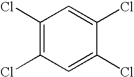
| chloranil |
 |
|
| |
11,11,12,12-tetracyano- 2,6- naphthquinodimethane |
 |
| C60 | fullerene | |
| Hole | ||
| Transport | ||
| molecules | ||
| TPD |
 |
|
| mTADATA |
 |
|
| - NPD |
 |
|
| HTM-1 |
 |
|
| TPTE |
 |
|
| Electron | ||
| transport | ||
| molecules | ||
| t-Bu-PBD |
 |
|
| BND |
 |
|
| OXD-7 |
 |
|
| OXD-Star |
 |
|
| TAZ |
 |
|
| TABLE 2 | ||
| Abbreviated | ||
| name | Chemical name | formula |
| TTF | tetrathiafulvalene |
 |
| Pc | Phthalocyanine |
 |
| CuPc | Copper(II) phthalocyanine |
 |
| NiPc | Nickel(II) phthalocyanine |
 |
| CoPc | Cobalt(II) phthalocyanine |
 |
| TMTSF | Tetramethyltetraselenafulvalene |
 |
| BEDT-TTF | Bis(ethylenedithioltetrathiafulvalene) |
 |
| BMDT-TTF | Bis(methylenedithio)tetrathiafulvalene |
 |
| TABLE 3 | ||
| Abbreviated | ||
| name | Chemical name | formula |
| Alq3 |
 |
|
| Bebq |
 |
|
| BAlq1 |
 |
|
| ZnPBO |
 |
|
| ZnPBT |
 |
|
| DTVBi |
 |
|
| DCM |
 |
|
| QA |
 |
|
| Rubrene |
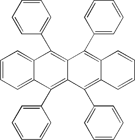 |
|
| Perylene |
 |
|
| DPVBi |
 |
|
| TABLE 4 | ||
| Abbreviated | ||
| name | Chemical name | formula |
| PA | Trans polyacetylene |
 |
| PDA | polydiacetylene |
 |
| PPP | Poly(p-phenylene) |
 |
| PPV | Poly(p phenylenevinylene) |
 |
| RO-PPV | Poly(2,5-dialkoxy- p-phenylenevinylene) |
 |
| MEH-PPV |
 |
|
| PPPv |
 |
|
| DHeO-CN-PPv |
 |
|
| MEH-CN-PPv |
 |
|
| Poly(3-alkyl- thiophene) |
 |
|
| Ladder poly(phenylene) |
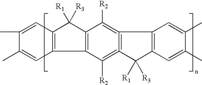 |
|
| Ladder PPP copolymer |
 |
|
| PT | Polythiophene |
 |
| P3AT | Poly(3- alkyithiophene) |
 |
| PTV | Poly(2,5- thiophenevinylene) |
 |
| PPy | Polypyrrole |
 |
| PAni | Polyaniline |
 |
| PEDOT |
 |
|
| Dopants for PEDOT |
 |
|
Claims (59)
Priority Applications (13)
| Application Number | Priority Date | Filing Date | Title |
|---|---|---|---|
| US10/218,141 US6784017B2 (en) | 2002-08-12 | 2002-08-12 | Method of creating a high performance organic semiconductor device |
| MXPA04010019A MXPA04010019A (en) | 2002-08-12 | 2003-04-10 | Method of creating a high performance organic semiconductor device. |
| JP2004527542A JP2005520356A (en) | 2002-08-12 | 2003-04-10 | Manufacturing method of high-performance organic semiconductor device |
| CA002450611A CA2450611A1 (en) | 2002-08-12 | 2003-04-10 | Method of creating a high performance organic semiconductor device |
| PCT/US2003/011125 WO2004015779A1 (en) | 2002-08-12 | 2003-04-10 | Method of creating a high performance organic semiconductor device |
| BR0303025-3A BR0303025A (en) | 2002-08-12 | 2003-04-10 | Method for forming a low resistance contact between a metallic material and an organic material from an organic semiconductor device and method for creating a high performance isolated gate field effect transistor |
| EP03784735A EP1529312A4 (en) | 2002-08-12 | 2003-04-10 | Method of creating a high performance organic semiconductor device |
| IL15832103A IL158321A0 (en) | 2002-08-12 | 2003-04-10 | A method of producing an organic semiconductor device |
| KR1020037015980A KR100729021B1 (en) | 2002-08-12 | 2003-04-10 | Method of creating a high performance organic semiconductor device |
| AU2003226074A AU2003226074A1 (en) | 2002-08-12 | 2003-04-10 | Method of creating a high performance organic semiconductor device |
| CNB038002280A CN100459147C (en) | 2002-08-12 | 2003-04-10 | Method of creating a high performance organic semiconductor device |
| TW092122137A TWI244760B (en) | 2002-08-12 | 2003-08-12 | Method of creating a high performance organic semiconductor device |
| US10/884,317 US20050003574A1 (en) | 2002-08-12 | 2004-07-01 | Method of creating a high performance organic semiconductor device |
Applications Claiming Priority (1)
| Application Number | Priority Date | Filing Date | Title |
|---|---|---|---|
| US10/218,141 US6784017B2 (en) | 2002-08-12 | 2002-08-12 | Method of creating a high performance organic semiconductor device |
Related Child Applications (1)
| Application Number | Title | Priority Date | Filing Date |
|---|---|---|---|
| US10/884,317 Division US20050003574A1 (en) | 2002-08-12 | 2004-07-01 | Method of creating a high performance organic semiconductor device |
Publications (2)
| Publication Number | Publication Date |
|---|---|
| US20040033641A1 US20040033641A1 (en) | 2004-02-19 |
| US6784017B2 true US6784017B2 (en) | 2004-08-31 |
Family
ID=31714501
Family Applications (2)
| Application Number | Title | Priority Date | Filing Date |
|---|---|---|---|
| US10/218,141 Expired - Fee Related US6784017B2 (en) | 2002-08-12 | 2002-08-12 | Method of creating a high performance organic semiconductor device |
| US10/884,317 Abandoned US20050003574A1 (en) | 2002-08-12 | 2004-07-01 | Method of creating a high performance organic semiconductor device |
Family Applications After (1)
| Application Number | Title | Priority Date | Filing Date |
|---|---|---|---|
| US10/884,317 Abandoned US20050003574A1 (en) | 2002-08-12 | 2004-07-01 | Method of creating a high performance organic semiconductor device |
Country Status (12)
| Country | Link |
|---|---|
| US (2) | US6784017B2 (en) |
| EP (1) | EP1529312A4 (en) |
| JP (1) | JP2005520356A (en) |
| KR (1) | KR100729021B1 (en) |
| CN (1) | CN100459147C (en) |
| AU (1) | AU2003226074A1 (en) |
| BR (1) | BR0303025A (en) |
| CA (1) | CA2450611A1 (en) |
| IL (1) | IL158321A0 (en) |
| MX (1) | MXPA04010019A (en) |
| TW (1) | TWI244760B (en) |
| WO (1) | WO2004015779A1 (en) |
Cited By (18)
| Publication number | Priority date | Publication date | Assignee | Title |
|---|---|---|---|---|
| US20050003574A1 (en) * | 2002-08-12 | 2005-01-06 | Yang Yang | Method of creating a high performance organic semiconductor device |
| US20050035430A1 (en) * | 2000-11-28 | 2005-02-17 | Beigel Michael L. | Rectifying charge storage element |
| US20050040757A1 (en) * | 2003-07-25 | 2005-02-24 | University Of Rochester | Light-emitting organic oligomer compositions |
| US20050281082A1 (en) * | 2004-06-17 | 2005-12-22 | Canon Kabushiki Kaisha | Non-volatile memory using organic bistable device |
| US20070018832A1 (en) * | 2005-07-19 | 2007-01-25 | Precision Dynamics Corporation | Semi-active rfid tag and related processes |
| WO2007058436A1 (en) * | 2005-11-15 | 2007-05-24 | Iferro Co., Ltd. | Memory device |
| US20070241325A1 (en) * | 2004-06-10 | 2007-10-18 | Yamanashi University | Schottky Gate Organic Field Effect Transistor and Fabrication Method of the Same |
| US20080254568A1 (en) * | 2004-04-27 | 2008-10-16 | Koninklijke Philips Electronics, N.V. | Composition and Method of Forming a Device |
| US20090032806A1 (en) * | 2006-10-18 | 2009-02-05 | Tsinghua University | Polymer composite p-n junction and method for manufacturing same and polymer composite diode incorporating same |
| US20090121874A1 (en) * | 2004-10-18 | 2009-05-14 | Semiconductor Energy Laboratory Co., Ltd. | Semiconductor device and driving method of the same |
| KR100966302B1 (en) * | 2005-11-15 | 2010-06-28 | 서울시립대학교 산학협력단 | Memory Device |
| US20110028644A1 (en) * | 2009-06-30 | 2011-02-03 | Plextronics, Inc. | Novel compositions, methods and polymers |
| US20130213461A1 (en) * | 2010-02-22 | 2013-08-22 | Mitsunaga Saito | Photovoltaic cell and method for manufacturing the same |
| US8585852B2 (en) | 1999-06-16 | 2013-11-19 | Vanguard Identification Systems, Inc. | Methods of making printed planar radio frequency identification elements |
| US8636220B2 (en) | 2006-12-29 | 2014-01-28 | Vanguard Identification Systems, Inc. | Printed planar RFID element wristbands and like personal identification devices |
| US8654018B2 (en) | 2005-04-06 | 2014-02-18 | Vanguard Identificaiton Systems, Inc. | Printed planar RFID element wristbands and like personal identification devices |
| US10367049B2 (en) | 2005-11-04 | 2019-07-30 | Interdigital Ce Patent Holdings | Electro-optical element integrating an organic electroluminescent diode and an organic transistor for modulating said diode |
| US10999919B2 (en) | 2019-07-11 | 2021-05-04 | Toyota Motor Engineering & Manufacturing North America, Inc. | Flexible electronic assembly for placement on a vehicle motor assembly |
Families Citing this family (46)
| Publication number | Priority date | Publication date | Assignee | Title |
|---|---|---|---|---|
| EP1192676A1 (en) | 1999-06-21 | 2002-04-03 | Cambridge University Technical Services Limited | Aligned polymers for an organic tft |
| WO2001047043A1 (en) * | 1999-12-21 | 2001-06-28 | Plastic Logic Limited | Solution processed devices |
| US6946332B2 (en) * | 2002-03-15 | 2005-09-20 | Lucent Technologies Inc. | Forming nanoscale patterned thin film metal layers |
| US7229847B2 (en) * | 2002-03-15 | 2007-06-12 | Lucent Technologies Inc. | Forming electrical contacts to a molecular layer |
| US7135728B2 (en) * | 2002-09-30 | 2006-11-14 | Nanosys, Inc. | Large-area nanoenabled macroelectronic substrates and uses therefor |
| CA2499965C (en) * | 2002-09-30 | 2013-03-19 | Nanosys, Inc. | Large-area nanoenabled macroelectronic substrates and uses therefor |
| US7030666B2 (en) * | 2004-02-27 | 2006-04-18 | Motorola, Inc. | Organic semiconductor inverting circuit |
| JP2005268550A (en) * | 2004-03-18 | 2005-09-29 | Japan Science & Technology Agency | Organic semiconductor, semiconductor device using the same, and method of manufacturing the same |
| JP2005332991A (en) * | 2004-05-20 | 2005-12-02 | Univ Nagoya | Carbon nanotube light emitting element |
| US20060014044A1 (en) * | 2004-07-14 | 2006-01-19 | Au Optronics Corporation | Organic light-emitting display with multiple light-emitting modules |
| US20060060839A1 (en) * | 2004-09-22 | 2006-03-23 | Chandross Edwin A | Organic semiconductor composition |
| EP1851811B1 (en) * | 2005-02-22 | 2019-05-08 | Commissariat à l'Energie Atomique et aux Energies Alternatives | Organic light-emitting diode with doped layers |
| US20060261433A1 (en) * | 2005-05-23 | 2006-11-23 | Harish Manohara | Nanotube Schottky diodes for high-frequency applications |
| KR100691276B1 (en) * | 2005-08-25 | 2007-03-12 | 삼성전기주식회사 | Nanowire light emitting device and method of fabricating the same |
| KR100730179B1 (en) * | 2005-12-09 | 2007-06-19 | 삼성에스디아이 주식회사 | Method of manufacturing organic thin film transistor |
| KR100695166B1 (en) * | 2006-01-03 | 2007-03-14 | 삼성전자주식회사 | Manufacturing method phase-change ram comprising fullerene layer |
| KR100897881B1 (en) * | 2006-06-02 | 2009-05-18 | 삼성전자주식회사 | Memory of fabricating organic memory device employing stack of organic material layer and buckminster fullerene layer as a data storage element |
| KR20080026957A (en) * | 2006-09-22 | 2008-03-26 | 삼성전자주식회사 | Method for manufacturing thin film transistor array panel |
| EP1912268B1 (en) * | 2006-10-09 | 2020-01-01 | Novaled GmbH | Method for spatial structuring the emission density of an OLED, semiconductor device obtained by the method and its use |
| JP5183913B2 (en) * | 2006-11-24 | 2013-04-17 | 住友電工デバイス・イノベーション株式会社 | Manufacturing method of semiconductor device |
| KR100785037B1 (en) * | 2006-12-13 | 2007-12-12 | 삼성전자주식회사 | Gainzno diode |
| TW200845220A (en) * | 2007-05-04 | 2008-11-16 | Univ Nat Chiao Tung | Microwave annealing for enhancing the efficiency of polymer photovoltaic device |
| WO2009049744A1 (en) * | 2007-10-18 | 2009-04-23 | Merck Patent Gmbh | Conducting formulation |
| FR2925728B1 (en) * | 2007-12-20 | 2010-01-01 | Commissariat Energie Atomique | METHOD FOR MANUFACTURING ORGANIC DIODE IDENTIFICATION AND AUTHENTICATION DEVICE, DEVICE AND METHOD OF USE |
| US7888169B2 (en) | 2007-12-26 | 2011-02-15 | Organicid, Inc. | Organic semiconductor device and method of manufacturing the same |
| EP2300225A1 (en) * | 2008-07-08 | 2011-03-30 | DSM IP Assets B.V. | A laminate and composite layer comprising a substrate and a coating, and a process and apparatus for preparation thereof |
| US8614423B2 (en) * | 2009-02-02 | 2013-12-24 | Redlen Technologies, Inc. | Solid-state radiation detector with improved sensitivity |
| US9202961B2 (en) | 2009-02-02 | 2015-12-01 | Redlen Technologies | Imaging devices with solid-state radiation detector with improved sensitivity |
| EP2251920A1 (en) | 2009-05-12 | 2010-11-17 | Università Degli Studi Di Milano - Bicocca | Method of manufacturing electrical contacts on organic semiconductors |
| JP2011035037A (en) * | 2009-07-30 | 2011-02-17 | Sony Corp | Method for producing circuit board and circuit board |
| KR101052145B1 (en) * | 2009-08-20 | 2011-07-26 | 성균관대학교산학협력단 | Target manufacturing method for iron-arsenic based superconducting thin film |
| TWI408840B (en) * | 2009-09-16 | 2013-09-11 | Nat Univ Tsing Hua | Method for fabricating and repairing organic thin film transistor |
| US8497499B2 (en) * | 2009-10-12 | 2013-07-30 | Georgia Tech Research Corporation | Method to modify the conductivity of graphene |
| TWI484626B (en) * | 2012-02-21 | 2015-05-11 | Formosa Epitaxy Inc | Semiconductor light-emitting component and light-emitting device having same |
| EP2917382A4 (en) | 2012-11-06 | 2016-07-06 | Oti Lumionics Inc | Method for depositing a conductive coating on a surface |
| US9629020B2 (en) * | 2013-05-28 | 2017-04-18 | Rivada Networks, Llc | Methods and systems for data context and management via dynamic spectrum controller and dynamic spectrum policy controller |
| DE102014211602B4 (en) * | 2014-06-17 | 2018-10-25 | Siemens Healthcare Gmbh | Detector module for an X-ray detector |
| GB2527754A (en) * | 2014-06-27 | 2016-01-06 | Cambridge Display Tech Ltd | Display systems |
| KR101653091B1 (en) * | 2015-01-30 | 2016-09-01 | 인천대학교 산학협력단 | Method for improving contact properties between polythiophene film and metal electrode using thermal treatment |
| US9947895B2 (en) | 2015-06-17 | 2018-04-17 | Universal Display Corporation | Flexible AMOLED display |
| CN114975823A (en) | 2015-12-16 | 2022-08-30 | Oti领英有限公司 | Optoelectronic device comprising a barrier coating |
| WO2018033860A1 (en) | 2016-08-15 | 2018-02-22 | Oti Lumionics Inc. | Light transmissive electrode for light emitting devices |
| KR102106774B1 (en) * | 2017-12-11 | 2020-05-28 | 한국생산기술연구원 | Organic memory being changed current density using laser beam |
| CN110148581B (en) * | 2018-02-10 | 2022-05-17 | 姜富帅 | Metallization process and method of metal-semiconductor |
| CN110676232B (en) * | 2019-08-30 | 2022-05-24 | 华为技术有限公司 | Semiconductor device packaging structure, manufacturing method thereof and electronic equipment |
| KR102306947B1 (en) * | 2020-05-21 | 2021-09-30 | 한국과학기술원 | Photodetectors based on Schottky junction and detecting photolight using the same |
Citations (37)
| Publication number | Priority date | Publication date | Assignee | Title |
|---|---|---|---|---|
| US4557978A (en) * | 1983-12-12 | 1985-12-10 | Primary Energy Research Corporation | Electroactive polymeric thin films |
| US4962088A (en) | 1987-12-22 | 1990-10-09 | General Motors Corporation | Formation of film superconductors by metallo-organic deposition |
| US5213983A (en) | 1990-01-04 | 1993-05-25 | Neste Oy | Method for the preparation of electronic and electro-optical components and circuits using conductive polymers |
| US5250388A (en) | 1988-05-31 | 1993-10-05 | Westinghouse Electric Corp. | Production of highly conductive polymers for electronic circuits |
| US5399502A (en) * | 1989-04-20 | 1995-03-21 | Cambridge Display Technology Limited | Method of manufacturing of electrolumineschent devices |
| US5574291A (en) | 1994-12-09 | 1996-11-12 | Lucent Technologies Inc. | Article comprising a thin film transistor with low conductivity organic layer |
| US5861219A (en) * | 1997-04-15 | 1999-01-19 | The Trustees Of Princeton University | Organic light emitting devices containing a metal complex of 5-hydroxy-quinoxaline as a host material |
| US5969376A (en) | 1996-08-23 | 1999-10-19 | Lucent Technologies Inc. | Organic thin film transistor having a phthalocyanine semiconductor layer |
| US5986206A (en) * | 1997-12-10 | 1999-11-16 | Nanogram Corporation | Solar cell |
| US6177859B1 (en) | 1997-10-21 | 2001-01-23 | Micron Technology, Inc. | Radio frequency communication apparatus and methods of forming a radio frequency communication apparatus |
| US6204515B1 (en) | 1999-01-15 | 2001-03-20 | The Dow Chemical Company | Semiconducting polymer field effect transistor |
| US6207034B1 (en) | 1997-12-05 | 2001-03-27 | Massachusetts Institute Of Technology | Method of manufacture of polymer transistors with controllable gap |
| US6207472B1 (en) | 1999-03-09 | 2001-03-27 | International Business Machines Corporation | Low temperature thin film transistor fabrication |
| US6241921B1 (en) | 1998-05-15 | 2001-06-05 | Massachusetts Institute Of Technology | Heterogeneous display elements and methods for their fabrication |
| US6246102B1 (en) | 1990-09-28 | 2001-06-12 | Texas Instruments Incorporated | Integrated circuits, transistors, data processing systems, printed wiring boards, digital computers, smart power devices, and processes of manufacture |
| US6249076B1 (en) | 1998-04-14 | 2001-06-19 | Massachusetts Institute Of Technology | Conducting polymer actuator |
| US6265243B1 (en) | 1999-03-29 | 2001-07-24 | Lucent Technologies Inc. | Process for fabricating organic circuits |
| US6278127B1 (en) | 1994-12-09 | 2001-08-21 | Agere Systems Guardian Corp. | Article comprising an organic thin film transistor adapted for biasing to form a N-type or a P-type transistor |
| US6291126B2 (en) | 1999-01-15 | 2001-09-18 | 3M Innovative Properties Company | Thermal transfer element and process for forming organic electroluminescent devices |
| US6307605B1 (en) | 1997-07-25 | 2001-10-23 | Eveready Battery Company, Inc. | Liquid crystal display and battery label including a liquid crystal display |
| US20010036561A1 (en) | 1999-01-15 | 2001-11-01 | 3M Innovative Properties Company | Multilayer devices formed by multilayer thermal transfer |
| US6320200B1 (en) | 1992-06-01 | 2001-11-20 | Yale University | Sub-nanoscale electronic devices and processes |
| US6329226B1 (en) | 2000-06-01 | 2001-12-11 | Agere Systems Guardian Corp. | Method for fabricating a thin-film transistor |
| US6335539B1 (en) | 1999-11-05 | 2002-01-01 | International Business Machines Corporation | Method for improving performance of organic semiconductors in bottom electrode structure |
| US6340789B1 (en) * | 1998-03-20 | 2002-01-22 | Cambridge Display Technology Limited | Multilayer photovoltaic or photoconductive devices |
| US20020012445A1 (en) | 2000-07-25 | 2002-01-31 | Perry Burt W. | Authentication watermarks for printed objects and related applications |
| US20020015024A1 (en) | 1998-01-26 | 2002-02-07 | University Of Delaware | Method and apparatus for integrating manual input |
| US20020019296A1 (en) | 1998-06-24 | 2002-02-14 | Viztec, Inc., A Delaware Corporation | Wearable device |
| US20020086554A1 (en) * | 2000-12-29 | 2002-07-04 | O'donnell Robert J. | Boron nitride/yttria composite components of semiconductor processing equipment and method of manufacturing thereof |
| US6433359B1 (en) * | 2001-09-06 | 2002-08-13 | 3M Innovative Properties Company | Surface modifying layers for organic thin film transistors |
| US6445006B1 (en) * | 1995-12-20 | 2002-09-03 | Advanced Technology Materials, Inc. | Microelectronic and microelectromechanical devices comprising carbon nanotube components, and methods of making same |
| US6472705B1 (en) * | 1998-11-18 | 2002-10-29 | International Business Machines Corporation | Molecular memory & logic |
| US6515298B2 (en) * | 1999-07-21 | 2003-02-04 | The Trustees Of Princeton University | Intersystem crossing agents for efficient utilization of excitons in organic light emitting devices |
| US6534329B2 (en) * | 1991-02-27 | 2003-03-18 | The Regents Of The University Of California | Visible light emitting diodes fabricated from soluble semiconducting polymers |
| US6555411B1 (en) | 2001-12-18 | 2003-04-29 | Lucent Technologies Inc. | Thin film transistors |
| US6580027B2 (en) * | 2001-06-11 | 2003-06-17 | Trustees Of Princeton University | Solar cells using fullerenes |
| US6617609B2 (en) * | 2001-11-05 | 2003-09-09 | 3M Innovative Properties Company | Organic thin film transistor with siloxane polymer interface |
Family Cites Families (62)
| Publication number | Priority date | Publication date | Assignee | Title |
|---|---|---|---|---|
| US6492966B1 (en) * | 1982-09-17 | 2002-12-10 | Alton O. Christensen | Integrally fabricated gated pixel elements and control circuitry for flat-panel displays |
| US5107308A (en) * | 1986-07-04 | 1992-04-21 | Mitsubishi Denki Kabushiki Kaisha | Field-effect transistor |
| DE69110922T2 (en) * | 1990-02-23 | 1995-12-07 | Sumitomo Chemical Co | Organic electroluminescent device. |
| US5429884A (en) * | 1992-01-17 | 1995-07-04 | Pioneer Electronic Corporation | Organic electroluminescent element |
| US5917980A (en) * | 1992-03-06 | 1999-06-29 | Fujitsu Limited | Optical circuit device, its manufacturing process and a multilayer optical circuit using said optical circuit device |
| KR940009496B1 (en) * | 1992-06-09 | 1994-10-14 | 주식회사금성사 | El color display device and manufacturing method thereof |
| US5334539A (en) * | 1993-01-29 | 1994-08-02 | Iowa State University Research Foundation, Inc. | Fabrication of poly(p-phenyleneacetylene) light-emitting diodes |
| US5352906A (en) * | 1993-01-29 | 1994-10-04 | Iowa State University Research Foundation, Inc. | Poly (p-phenyleneneacetylene) light-emitting diodes |
| JP3246189B2 (en) * | 1994-06-28 | 2002-01-15 | 株式会社日立製作所 | Semiconductor display device |
| US5747928A (en) * | 1994-10-07 | 1998-05-05 | Iowa State University Research Foundation, Inc. | Flexible panel display having thin film transistors driving polymer light-emitting diodes |
| GB2296815B (en) * | 1994-12-09 | 1999-03-17 | Cambridge Display Tech Ltd | Photoresponsive materials |
| TW293172B (en) * | 1994-12-09 | 1996-12-11 | At & T Corp | |
| US5703436A (en) * | 1994-12-13 | 1997-12-30 | The Trustees Of Princeton University | Transparent contacts for organic devices |
| US6225218B1 (en) * | 1995-12-20 | 2001-05-01 | Semiconductor Energy Laboratory Co., Ltd. | Semiconductor device and its manufacturing method |
| US6326640B1 (en) * | 1996-01-29 | 2001-12-04 | Motorola, Inc. | Organic thin film transistor with enhanced carrier mobility |
| US5656883A (en) * | 1996-08-06 | 1997-08-12 | Christensen; Alton O. | Field emission devices with improved field emission surfaces |
| US5946551A (en) * | 1997-03-25 | 1999-08-31 | Dimitrakopoulos; Christos Dimitrios | Fabrication of thin film effect transistor comprising an organic semiconductor and chemical solution deposited metal oxide gate dielectric |
| JPH113868A (en) * | 1997-06-12 | 1999-01-06 | Nec Yamagata Ltd | Device and method for lamp annealing |
| US5977718A (en) * | 1997-08-08 | 1999-11-02 | Christensen; Alton O. | Gated pixel elements using polymer electroluminescent materials for panel displays |
| EP0968537B1 (en) * | 1997-08-22 | 2012-05-02 | Creator Technology B.V. | A method of manufacturing a field-effect transistor substantially consisting of organic materials |
| JPH11274468A (en) * | 1998-03-25 | 1999-10-08 | Sony Corp | Ohmic electrode and its forming method, and laminate for forming ohmic electrode |
| US6873098B2 (en) * | 1998-12-22 | 2005-03-29 | Alton O. Christensen, Sr. | Electroluminescent devices and displays with integrally fabricated address and logic devices fabricated by printing or weaving |
| US6229259B1 (en) * | 1998-12-22 | 2001-05-08 | Alton O. Christensen, Sr. | Woven polymer fiber video displays with improved efficiency and economy of manufacture |
| US20020008464A1 (en) * | 1998-12-22 | 2002-01-24 | Christensen Alton O. | Woven or ink jet printed arrays for extreme UV and X-ray source and detector |
| NO314525B1 (en) * | 1999-04-22 | 2003-03-31 | Thin Film Electronics Asa | Process for the preparation of organic semiconductor devices in thin film |
| GB9910964D0 (en) * | 1999-05-12 | 1999-07-14 | Secr Defence | Conducting polymers |
| EP1192676A1 (en) * | 1999-06-21 | 2002-04-03 | Cambridge University Technical Services Limited | Aligned polymers for an organic tft |
| US6414104B1 (en) * | 1999-07-20 | 2002-07-02 | Sri International | Arylamine-substituted poly (arylene vinylenes) and associated methods of preparation and use |
| US6312971B1 (en) * | 1999-08-31 | 2001-11-06 | E Ink Corporation | Solvent annealing process for forming a thin semiconductor film with advantageous properties |
| US6136702A (en) * | 1999-11-29 | 2000-10-24 | Lucent Technologies Inc. | Thin film transistors |
| US6265127B1 (en) * | 1999-12-15 | 2001-07-24 | Eastman Kodak Company | 1, 4-dihydrophyridine charge control agents for electrostatographic toners and developers |
| WO2001047043A1 (en) * | 1999-12-21 | 2001-06-28 | Plastic Logic Limited | Solution processed devices |
| EP1243035B1 (en) * | 1999-12-21 | 2016-03-02 | Flexenable Limited | Forming interconnects |
| AU781789B2 (en) * | 1999-12-21 | 2005-06-16 | Flexenable Limited | Solution processing |
| KR100940110B1 (en) * | 1999-12-21 | 2010-02-02 | 플라스틱 로직 리미티드 | Inkjet-fabricated intergrated circuits amd method for forming electronic device |
| US20010046113A1 (en) * | 2000-02-09 | 2001-11-29 | Schmidt David G. | Alloy Compositions for use as electrode materials and for hydrogen production |
| US20020068373A1 (en) * | 2000-02-16 | 2002-06-06 | Nova Crystals, Inc. | Method for fabricating light emitting diodes |
| AT411305B (en) * | 2002-05-22 | 2003-11-25 | Qsel Quantum Solar Energy Linz | Post-treatment method for photovoltaic cell using thermal treatment at temperature above glass transition temperature of electron donor |
| US20020121669A1 (en) * | 2000-04-28 | 2002-09-05 | Batlogg Bertham Josef | Organic superconductive field-effect switching device |
| US6734623B1 (en) * | 2000-07-31 | 2004-05-11 | Xerox Corporation | Annealed organic light emitting devices and method of annealing organic light emitting devices |
| JP4094804B2 (en) * | 2000-10-17 | 2008-06-04 | 三星エスディアイ株式会社 | Manufacturing method of organic EL device |
| US6765348B2 (en) * | 2001-01-26 | 2004-07-20 | Xerox Corporation | Electroluminescent devices containing thermal protective layers |
| US7439096B2 (en) * | 2001-02-21 | 2008-10-21 | Lucent Technologies Inc. | Semiconductor device encapsulation |
| EP1393389B1 (en) * | 2001-05-23 | 2018-12-05 | Flexenable Limited | Laser patterning of devices |
| US7002223B2 (en) * | 2001-07-27 | 2006-02-21 | Samsung Electronics Co., Ltd. | Semiconductor device having elevated source/drain |
| DE60238123D1 (en) * | 2001-08-09 | 2010-12-09 | Asahi Chemical Ind | ORGANIC SEMICONDUCTOR LAYER AND METHOD FOR THE PRODUCTION THEREOF |
| US7071123B2 (en) * | 2001-08-24 | 2006-07-04 | Gracel Display Inc. | Fabrication method for organic semiconductor transistor having organic polymeric gate insulating layer |
| US6946676B2 (en) * | 2001-11-05 | 2005-09-20 | 3M Innovative Properties Company | Organic thin film transistor with polymeric interface |
| CN1157807C (en) * | 2001-11-09 | 2004-07-14 | 清华大学 | Organic film FET and its manufacture |
| US7026178B2 (en) * | 2001-11-13 | 2006-04-11 | Applied Optoelectronics, Inc. | Method for fabricating a VCSEL with ion-implanted current-confinement structure |
| US6603141B2 (en) * | 2001-12-28 | 2003-08-05 | Motorola, Inc. | Organic semiconductor and method |
| US6620657B2 (en) * | 2002-01-15 | 2003-09-16 | International Business Machines Corporation | Method of forming a planar polymer transistor using substrate bonding techniques |
| US6795478B2 (en) * | 2002-03-28 | 2004-09-21 | Applied Optoelectronics, Inc. | VCSEL with antiguide current confinement layer |
| US20030183915A1 (en) * | 2002-04-02 | 2003-10-02 | Motorola, Inc. | Encapsulated organic semiconductor device and method |
| KR100456470B1 (en) * | 2002-04-19 | 2004-11-10 | 주식회사 비아트론 | Apparatuses for heat treatment of semiconductor films under low temperature |
| US6667215B2 (en) * | 2002-05-02 | 2003-12-23 | 3M Innovative Properties | Method of making transistors |
| US20030227014A1 (en) * | 2002-06-11 | 2003-12-11 | Xerox Corporation. | Process for forming semiconductor layer of micro-and nano-electronic devices |
| US6661024B1 (en) * | 2002-07-02 | 2003-12-09 | Motorola, Inc. | Integrated circuit including field effect transistor and method of manufacture |
| US6784017B2 (en) * | 2002-08-12 | 2004-08-31 | Precision Dynamics Corporation | Method of creating a high performance organic semiconductor device |
| US7923782B2 (en) * | 2004-02-27 | 2011-04-12 | International Business Machines Corporation | Hybrid SOI/bulk semiconductor transistors |
| JP4528062B2 (en) * | 2004-08-25 | 2010-08-18 | 富士通株式会社 | Semiconductor device and manufacturing method thereof |
| TW200826290A (en) * | 2006-12-01 | 2008-06-16 | Univ Nat Chiao Tung | Vertical organic transistor and manufacturing method thereof |
-
2002
- 2002-08-12 US US10/218,141 patent/US6784017B2/en not_active Expired - Fee Related
-
2003
- 2003-04-10 BR BR0303025-3A patent/BR0303025A/en not_active IP Right Cessation
- 2003-04-10 WO PCT/US2003/011125 patent/WO2004015779A1/en not_active Application Discontinuation
- 2003-04-10 CN CNB038002280A patent/CN100459147C/en not_active Expired - Fee Related
- 2003-04-10 KR KR1020037015980A patent/KR100729021B1/en not_active IP Right Cessation
- 2003-04-10 EP EP03784735A patent/EP1529312A4/en not_active Withdrawn
- 2003-04-10 IL IL15832103A patent/IL158321A0/en unknown
- 2003-04-10 JP JP2004527542A patent/JP2005520356A/en active Pending
- 2003-04-10 MX MXPA04010019A patent/MXPA04010019A/en unknown
- 2003-04-10 AU AU2003226074A patent/AU2003226074A1/en not_active Abandoned
- 2003-04-10 CA CA002450611A patent/CA2450611A1/en not_active Abandoned
- 2003-08-12 TW TW092122137A patent/TWI244760B/en not_active IP Right Cessation
-
2004
- 2004-07-01 US US10/884,317 patent/US20050003574A1/en not_active Abandoned
Patent Citations (39)
| Publication number | Priority date | Publication date | Assignee | Title |
|---|---|---|---|---|
| US4557978A (en) * | 1983-12-12 | 1985-12-10 | Primary Energy Research Corporation | Electroactive polymeric thin films |
| US4962088A (en) | 1987-12-22 | 1990-10-09 | General Motors Corporation | Formation of film superconductors by metallo-organic deposition |
| US5250388A (en) | 1988-05-31 | 1993-10-05 | Westinghouse Electric Corp. | Production of highly conductive polymers for electronic circuits |
| US5399502A (en) * | 1989-04-20 | 1995-03-21 | Cambridge Display Technology Limited | Method of manufacturing of electrolumineschent devices |
| US5213983A (en) | 1990-01-04 | 1993-05-25 | Neste Oy | Method for the preparation of electronic and electro-optical components and circuits using conductive polymers |
| US6246102B1 (en) | 1990-09-28 | 2001-06-12 | Texas Instruments Incorporated | Integrated circuits, transistors, data processing systems, printed wiring boards, digital computers, smart power devices, and processes of manufacture |
| US6534329B2 (en) * | 1991-02-27 | 2003-03-18 | The Regents Of The University Of California | Visible light emitting diodes fabricated from soluble semiconducting polymers |
| US6320200B1 (en) | 1992-06-01 | 2001-11-20 | Yale University | Sub-nanoscale electronic devices and processes |
| US5574291A (en) | 1994-12-09 | 1996-11-12 | Lucent Technologies Inc. | Article comprising a thin film transistor with low conductivity organic layer |
| US6278127B1 (en) | 1994-12-09 | 2001-08-21 | Agere Systems Guardian Corp. | Article comprising an organic thin film transistor adapted for biasing to form a N-type or a P-type transistor |
| US6445006B1 (en) * | 1995-12-20 | 2002-09-03 | Advanced Technology Materials, Inc. | Microelectronic and microelectromechanical devices comprising carbon nanotube components, and methods of making same |
| US5969376A (en) | 1996-08-23 | 1999-10-19 | Lucent Technologies Inc. | Organic thin film transistor having a phthalocyanine semiconductor layer |
| US5861219A (en) * | 1997-04-15 | 1999-01-19 | The Trustees Of Princeton University | Organic light emitting devices containing a metal complex of 5-hydroxy-quinoxaline as a host material |
| US6307605B1 (en) | 1997-07-25 | 2001-10-23 | Eveready Battery Company, Inc. | Liquid crystal display and battery label including a liquid crystal display |
| US6177859B1 (en) | 1997-10-21 | 2001-01-23 | Micron Technology, Inc. | Radio frequency communication apparatus and methods of forming a radio frequency communication apparatus |
| US6207034B1 (en) | 1997-12-05 | 2001-03-27 | Massachusetts Institute Of Technology | Method of manufacture of polymer transistors with controllable gap |
| US5986206A (en) * | 1997-12-10 | 1999-11-16 | Nanogram Corporation | Solar cell |
| US20020015024A1 (en) | 1998-01-26 | 2002-02-07 | University Of Delaware | Method and apparatus for integrating manual input |
| US6340789B1 (en) * | 1998-03-20 | 2002-01-22 | Cambridge Display Technology Limited | Multilayer photovoltaic or photoconductive devices |
| US6249076B1 (en) | 1998-04-14 | 2001-06-19 | Massachusetts Institute Of Technology | Conducting polymer actuator |
| US6241921B1 (en) | 1998-05-15 | 2001-06-05 | Massachusetts Institute Of Technology | Heterogeneous display elements and methods for their fabrication |
| US20020019296A1 (en) | 1998-06-24 | 2002-02-14 | Viztec, Inc., A Delaware Corporation | Wearable device |
| US6472705B1 (en) * | 1998-11-18 | 2002-10-29 | International Business Machines Corporation | Molecular memory & logic |
| US20020015907A1 (en) | 1999-01-15 | 2002-02-07 | 3M Innovative Properties Company | Thermal transfer element and process for forming organic electroluminescent devices |
| US6291126B2 (en) | 1999-01-15 | 2001-09-18 | 3M Innovative Properties Company | Thermal transfer element and process for forming organic electroluminescent devices |
| US6204515B1 (en) | 1999-01-15 | 2001-03-20 | The Dow Chemical Company | Semiconducting polymer field effect transistor |
| US20010036561A1 (en) | 1999-01-15 | 2001-11-01 | 3M Innovative Properties Company | Multilayer devices formed by multilayer thermal transfer |
| US6207472B1 (en) | 1999-03-09 | 2001-03-27 | International Business Machines Corporation | Low temperature thin film transistor fabrication |
| US20010029103A1 (en) | 1999-03-29 | 2001-10-11 | Katz Howard Edan | Process for fabricating organic circuits |
| US6265243B1 (en) | 1999-03-29 | 2001-07-24 | Lucent Technologies Inc. | Process for fabricating organic circuits |
| US6515298B2 (en) * | 1999-07-21 | 2003-02-04 | The Trustees Of Princeton University | Intersystem crossing agents for efficient utilization of excitons in organic light emitting devices |
| US6335539B1 (en) | 1999-11-05 | 2002-01-01 | International Business Machines Corporation | Method for improving performance of organic semiconductors in bottom electrode structure |
| US6329226B1 (en) | 2000-06-01 | 2001-12-11 | Agere Systems Guardian Corp. | Method for fabricating a thin-film transistor |
| US20020012445A1 (en) | 2000-07-25 | 2002-01-31 | Perry Burt W. | Authentication watermarks for printed objects and related applications |
| US20020086554A1 (en) * | 2000-12-29 | 2002-07-04 | O'donnell Robert J. | Boron nitride/yttria composite components of semiconductor processing equipment and method of manufacturing thereof |
| US6580027B2 (en) * | 2001-06-11 | 2003-06-17 | Trustees Of Princeton University | Solar cells using fullerenes |
| US6433359B1 (en) * | 2001-09-06 | 2002-08-13 | 3M Innovative Properties Company | Surface modifying layers for organic thin film transistors |
| US6617609B2 (en) * | 2001-11-05 | 2003-09-09 | 3M Innovative Properties Company | Organic thin film transistor with siloxane polymer interface |
| US6555411B1 (en) | 2001-12-18 | 2003-04-29 | Lucent Technologies Inc. | Thin film transistors |
Non-Patent Citations (10)
| Title |
|---|
| EE Times article by R. Colin Johnson entitled "Nanotubes Self-Assemble into Circuit Elements", Mar. 26, 2002, http://www.eet.com.story/OEG20020326S0038, 7 pgs. |
| EPO Publication No. EP 1 005 013 B1 entitled "Display Comprising Organic Smart Pixels", Jul. 25, 2001. |
| PCT Publication No. WO 01/07993 A1 entitled, "Wearable Device", Feb. 1, 2001. |
| PCT Publication No. WO 01/17029 A1 entitled, "Transistor for an Electronically Driven Display", Mar. 8, 2001. |
| PCT Publication No. WO 01/20402 A1 entitled, "Fabrication of Finely Featured Devices by Liquid Embossing", Mar. 22, 2001. |
| PCT Publication No. WO 01/39111 A1 entitled, "Chip Card", May 31, 2001. |
| PCT Publication No. WO 01/46987 A2 entitled, "Inkjet-Fabricated Integrated Circuits", Jun. 28, 2001. |
| PCT Publication No. WO 01/95384 A1 entitled, "A Method of Electronic Component Fabrication and an Electronic Component", Dec. 13, 2001. |
| PCT Publication No. WO 02/09190 A1 entitled, "Transistor Gate Insulator Layer Incorporating Superfine Ceramic Particles", Jan. 31, 2002. |
| The Clock Magazine Mar./Apr. 2002 article entitled "The OLED Bazaar", Apr. 16, 2002, http://www/theclockmag.com.april/oledadobeedit.htm020326S0038, 21 pgs. |
Cited By (30)
| Publication number | Priority date | Publication date | Assignee | Title |
|---|---|---|---|---|
| US8585852B2 (en) | 1999-06-16 | 2013-11-19 | Vanguard Identification Systems, Inc. | Methods of making printed planar radio frequency identification elements |
| US20050035430A1 (en) * | 2000-11-28 | 2005-02-17 | Beigel Michael L. | Rectifying charge storage element |
| US6982452B2 (en) * | 2000-11-28 | 2006-01-03 | Precision Dynamics Corporation | Rectifying charge storage element |
| US20050003574A1 (en) * | 2002-08-12 | 2005-01-06 | Yang Yang | Method of creating a high performance organic semiconductor device |
| US20050040757A1 (en) * | 2003-07-25 | 2005-02-24 | University Of Rochester | Light-emitting organic oligomer compositions |
| US8241946B2 (en) * | 2004-04-27 | 2012-08-14 | Creator Technology B.V. | Method of forming an organic semiconducting device by a melt technique |
| US20080254568A1 (en) * | 2004-04-27 | 2008-10-16 | Koninklijke Philips Electronics, N.V. | Composition and Method of Forming a Device |
| US20070241325A1 (en) * | 2004-06-10 | 2007-10-18 | Yamanashi University | Schottky Gate Organic Field Effect Transistor and Fabrication Method of the Same |
| US20050281082A1 (en) * | 2004-06-17 | 2005-12-22 | Canon Kabushiki Kaisha | Non-volatile memory using organic bistable device |
| US7170779B2 (en) * | 2004-06-17 | 2007-01-30 | Canon Kabushiki Kaisha | Non-volatile memory using organic bistable device |
| US20090121874A1 (en) * | 2004-10-18 | 2009-05-14 | Semiconductor Energy Laboratory Co., Ltd. | Semiconductor device and driving method of the same |
| US8223531B2 (en) | 2004-10-18 | 2012-07-17 | Semiconductor Energy Laboratory Co., Ltd. | Semiconductor device and driving method of the same |
| US8089799B2 (en) * | 2004-10-18 | 2012-01-03 | Semiconductor Energy Laboratory Co., Ltd. | Semiconductor device and driving method of the same |
| US20110227137A1 (en) * | 2004-10-18 | 2011-09-22 | Semiconductor Energy Laboratory Co., Ltd. | Semiconductor device and driving method of the same |
| US8654018B2 (en) | 2005-04-06 | 2014-02-18 | Vanguard Identificaiton Systems, Inc. | Printed planar RFID element wristbands and like personal identification devices |
| US20070018832A1 (en) * | 2005-07-19 | 2007-01-25 | Precision Dynamics Corporation | Semi-active rfid tag and related processes |
| US8237561B2 (en) | 2005-07-19 | 2012-08-07 | Precision Dynamics Corporation | Semi-active RFID tag and related processes |
| US10367049B2 (en) | 2005-11-04 | 2019-07-30 | Interdigital Ce Patent Holdings | Electro-optical element integrating an organic electroluminescent diode and an organic transistor for modulating said diode |
| KR100966302B1 (en) * | 2005-11-15 | 2010-06-28 | 서울시립대학교 산학협력단 | Memory Device |
| WO2007058436A1 (en) * | 2005-11-15 | 2007-05-24 | Iferro Co., Ltd. | Memory device |
| US7858973B2 (en) | 2006-10-18 | 2010-12-28 | Tsinghua University | Polymer composite p-n junction and method for manufacturing same and polymer composite diode incorporating same |
| US20090032806A1 (en) * | 2006-10-18 | 2009-02-05 | Tsinghua University | Polymer composite p-n junction and method for manufacturing same and polymer composite diode incorporating same |
| US8636220B2 (en) | 2006-12-29 | 2014-01-28 | Vanguard Identification Systems, Inc. | Printed planar RFID element wristbands and like personal identification devices |
| US20110028644A1 (en) * | 2009-06-30 | 2011-02-03 | Plextronics, Inc. | Novel compositions, methods and polymers |
| US8440785B2 (en) | 2009-06-30 | 2013-05-14 | Plextronics, Inc. | Compositions, methods and polymers |
| US20130213461A1 (en) * | 2010-02-22 | 2013-08-22 | Mitsunaga Saito | Photovoltaic cell and method for manufacturing the same |
| US8980672B2 (en) * | 2010-02-22 | 2015-03-17 | Kabushiki Kaisha Toshiba | Photovoltaic cell and method for manufacturing the same |
| US20150155507A1 (en) * | 2010-02-22 | 2015-06-04 | Kabushiki Kaisha Toshiba | Photovoltaic cell and method for manufacturing the same |
| US9178171B2 (en) * | 2010-02-22 | 2015-11-03 | Kabushiki Kaisha Toshiba | Photovoltaic cell and method for manufacturing the same |
| US10999919B2 (en) | 2019-07-11 | 2021-05-04 | Toyota Motor Engineering & Manufacturing North America, Inc. | Flexible electronic assembly for placement on a vehicle motor assembly |
Also Published As
| Publication number | Publication date |
|---|---|
| CA2450611A1 (en) | 2004-02-12 |
| MXPA04010019A (en) | 2004-12-13 |
| KR100729021B1 (en) | 2007-06-14 |
| IL158321A0 (en) | 2004-06-01 |
| TWI244760B (en) | 2005-12-01 |
| WO2004015779A1 (en) | 2004-02-19 |
| US20040033641A1 (en) | 2004-02-19 |
| CN100459147C (en) | 2009-02-04 |
| AU2003226074A1 (en) | 2004-02-25 |
| TW200415787A (en) | 2004-08-16 |
| US20050003574A1 (en) | 2005-01-06 |
| KR20050026844A (en) | 2005-03-16 |
| JP2005520356A (en) | 2005-07-07 |
| BR0303025A (en) | 2004-08-10 |
| EP1529312A1 (en) | 2005-05-11 |
| CN1524295A (en) | 2004-08-25 |
| EP1529312A4 (en) | 2005-11-23 |
Similar Documents
| Publication | Publication Date | Title |
|---|---|---|
| US6784017B2 (en) | Method of creating a high performance organic semiconductor device | |
| Shaw et al. | Organic electronics: introduction | |
| TWI300273B (en) | ||
| JP4498961B2 (en) | Organic field effect transistor and flat panel display device having the same | |
| US7476893B2 (en) | Vertical organic field effect transistor | |
| US20080197343A1 (en) | Organic Field Effect Transistor Gate | |
| US20080237580A1 (en) | Organic Semiconductor Element and Organic El Display Device Using the Same | |
| KR20060080446A (en) | Vertical organic thin film transistor and organic light emitting transistor | |
| JP2012508964A (en) | Method for manufacturing organic thin film transistors using a laser thermal transfer process | |
| Semple et al. | Large-area plastic nanogap electronics enabled by adhesion lithography | |
| US8269211B2 (en) | Organic electronic device with an organic semiconductor layer | |
| US20060255336A1 (en) | Thin film transistor and method of manufacturing the same | |
| US7868322B2 (en) | Method for fabricating an organic thin film transistor by oxidation and selective reduction of organic semiconductor material | |
| KR101101479B1 (en) | Improvement of charge injection in organic thin film transistor by local doping | |
| Subramanian | Printed electronics | |
| Yadav | An Extensive Study of Various Performance Parameters of OTFTs using Trilayer Source Drain Electrodes | |
| Li et al. | Flexible Polymer Rectifying Diode on Plastic Foils with MoO 3 Hole Injection | |
| KR20070019634A (en) | Vertical organic field effect transistor | |
| Kim et al. | Device fabrications of organic thin-film transistors | |
| Garnier | Organic-based thin-film transistors | |
| KR20180039588A (en) | Organic field effect transistor and method for fabricating thereof | |
| Li | Organic Thin Film Transistor Integration | |
| Watanabe | Vertical-type organic transistor advances flexible sheet displays |
Legal Events
| Date | Code | Title | Description |
|---|---|---|---|
| AS | Assignment |
Owner name: PRECISION DYNAMICS CORPORATION, CALIFORNIA Free format text: ASSIGNMENT OF ASSIGNORS INTEREST;ASSIGNORS:YANG, YANG;MA, LIPING;BEIGEL, MICHAEL L.;REEL/FRAME:013205/0050 Effective date: 20020805 |
|
| FPAY | Fee payment |
Year of fee payment: 4 |
|
| AS | Assignment |
Owner name: WELLS FARGO BANK, NATIONAL ASSOCIATION, CALIFORNIA Free format text: SECURITY AGREEMENT;ASSIGNOR:PRECISION DYNAMICS CORPORATION;REEL/FRAME:021794/0545 Effective date: 20081103 |
|
| AS | Assignment |
Owner name: WELLS FARGO BANK, NATIONAL ASSOCIATION, AS ADMINIS Free format text: SECURITY AGREEMENT;ASSIGNORS:PRECISION DYNAMICS CORPORATION;THE ST. JOHN COMPANIES, INC.;REEL/FRAME:025539/0736 Effective date: 20101223 |
|
| REMI | Maintenance fee reminder mailed | ||
| LAPS | Lapse for failure to pay maintenance fees | ||
| STCH | Information on status: patent discontinuation |
Free format text: PATENT EXPIRED DUE TO NONPAYMENT OF MAINTENANCE FEES UNDER 37 CFR 1.362 |
|
| FP | Lapsed due to failure to pay maintenance fee |
Effective date: 20120831 |