US6796946B2 - Arteriostenosis inspecting apparatus and ankle-blood-pressure measuring apparatus - Google Patents
Arteriostenosis inspecting apparatus and ankle-blood-pressure measuring apparatus Download PDFInfo
- Publication number
- US6796946B2 US6796946B2 US10/370,503 US37050303A US6796946B2 US 6796946 B2 US6796946 B2 US 6796946B2 US 37050303 A US37050303 A US 37050303A US 6796946 B2 US6796946 B2 US 6796946B2
- Authority
- US
- United States
- Prior art keywords
- pressure
- ankle
- blood
- cuff
- pulse
- Prior art date
- Legal status (The legal status is an assumption and is not a legal conclusion. Google has not performed a legal analysis and makes no representation as to the accuracy of the status listed.)
- Expired - Fee Related
Links
Images


Classifications
-
- A—HUMAN NECESSITIES
- A61—MEDICAL OR VETERINARY SCIENCE; HYGIENE
- A61B—DIAGNOSIS; SURGERY; IDENTIFICATION
- A61B5/00—Measuring for diagnostic purposes; Identification of persons
- A61B5/02—Detecting, measuring or recording pulse, heart rate, blood pressure or blood flow; Combined pulse/heart-rate/blood pressure determination; Evaluating a cardiovascular condition not otherwise provided for, e.g. using combinations of techniques provided for in this group with electrocardiography or electroauscultation; Heart catheters for measuring blood pressure
- A61B5/021—Measuring pressure in heart or blood vessels
- A61B5/022—Measuring pressure in heart or blood vessels by applying pressure to close blood vessels, e.g. against the skin; Ophthalmodynamometers
- A61B5/02233—Occluders specially adapted therefor
-
- A—HUMAN NECESSITIES
- A61—MEDICAL OR VETERINARY SCIENCE; HYGIENE
- A61B—DIAGNOSIS; SURGERY; IDENTIFICATION
- A61B5/00—Measuring for diagnostic purposes; Identification of persons
- A61B5/02—Detecting, measuring or recording pulse, heart rate, blood pressure or blood flow; Combined pulse/heart-rate/blood pressure determination; Evaluating a cardiovascular condition not otherwise provided for, e.g. using combinations of techniques provided for in this group with electrocardiography or electroauscultation; Heart catheters for measuring blood pressure
- A61B5/021—Measuring pressure in heart or blood vessels
- A61B5/022—Measuring pressure in heart or blood vessels by applying pressure to close blood vessels, e.g. against the skin; Ophthalmodynamometers
- A61B5/0225—Measuring pressure in heart or blood vessels by applying pressure to close blood vessels, e.g. against the skin; Ophthalmodynamometers the pressure being controlled by electric signals, e.g. derived from Korotkoff sounds
- A61B5/02255—Measuring pressure in heart or blood vessels by applying pressure to close blood vessels, e.g. against the skin; Ophthalmodynamometers the pressure being controlled by electric signals, e.g. derived from Korotkoff sounds the pressure being controlled by plethysmographic signals, e.g. derived from optical sensors
-
- A—HUMAN NECESSITIES
- A61—MEDICAL OR VETERINARY SCIENCE; HYGIENE
- A61B—DIAGNOSIS; SURGERY; IDENTIFICATION
- A61B5/00—Measuring for diagnostic purposes; Identification of persons
- A61B5/68—Arrangements of detecting, measuring or recording means, e.g. sensors, in relation to patient
- A61B5/6801—Arrangements of detecting, measuring or recording means, e.g. sensors, in relation to patient specially adapted to be attached to or worn on the body surface
- A61B5/6813—Specially adapted to be attached to a specific body part
- A61B5/6828—Leg
-
- A—HUMAN NECESSITIES
- A61—MEDICAL OR VETERINARY SCIENCE; HYGIENE
- A61B—DIAGNOSIS; SURGERY; IDENTIFICATION
- A61B5/00—Measuring for diagnostic purposes; Identification of persons
- A61B5/68—Arrangements of detecting, measuring or recording means, e.g. sensors, in relation to patient
- A61B5/6801—Arrangements of detecting, measuring or recording means, e.g. sensors, in relation to patient specially adapted to be attached to or worn on the body surface
- A61B5/6813—Specially adapted to be attached to a specific body part
- A61B5/6824—Arm or wrist
Definitions
- the present invention relates to an arteriostenosis inspecting apparatus which inspects presence or absence of arteriostenosis of a living person, and an ankle-blood-pressure measuring apparatus which measures a blood-pressure of an ankle of a living subject.
- Atherosclerosis as a sort of arteriosclerosis is a disease that lipid, in particular, cholesterol deposits on walls of arteries and thereby thickens the arterial walls. Since atherosclerosis generates stenosis of an artery and thereby decreases its diameter, it is also called arteriostenosis or arteriosclerosis obliterans.
- arteriostenosis or arteriosclerosis obliterans.
- an inferior-and-superior-limb-blood-pressure-index measuring apparatus which can be used for inspecting arteriostenosis, by utilizing a fact that blood pressure lowers on a distal side of a body portion having arteriostenosis. The measuring apparatus is disclosed in, e.g., Japanese Patent No. 3,140,007 or its corresponding U.S. Pat. No. 6,355,000.
- the disclosed measuring apparatus includes a cuff worn on an inferior limb to measure a blood pressure of the inferior limb, and a cuff worn on a superior limb to measure a blood pressure of the superior limb, calculates an inferior-and-superior-limb blood-pressure index as a ratio of one of the inferior-limb blood pressure and the superior-limb blood pressure to the other, and inspects presence or absence of arteriosclerosis based on the thus calculated index.
- the index is calculated by dividing an inferior-limb systolic blood pressure by a superior-limb systolic blood pressure and, if the thus calculated index is greater than 0.9, it is judged that arteriostenosis is absent and, if the index is not greater than 0.9, it is judged that arteriostenosis is suspected.
- an ankle is selected as the inferior limb and a cuff is worn on the ankle.
- an ankle has two thick arteries, i.e., an anterior tibial artery and a posterior tibial artery.
- an anterior tibial artery i.e., an anterior tibial artery and a posterior tibial artery.
- blood pressure lowers on a distal side of a stenotic portion.
- an ankle has two thick arteries
- a blood pressure of the other artery free of stenosis does not lower
- the blood pressure of the other artery is measured as a blood pressure of the ankle.
- a measured blood pressure of the ankle may be normal
- an inferior-and-superior-limb blood-pressure index calculated based on the measured ankle blood pressure may be normal.
- the inferior-and-superior-limb blood-pressure index cannot be used for finding arteriostenosis.
- an ankle-blood-pressure measuring apparatus for measuring a blood pressure of an ankle of a living subject, comprising an inflatable cuff which is adapted to be worn on the ankle of the subject; a cuff-pressure changing device which decreases a pressure in the cuff from a pressure higher than a systolic blood pressure of the ankle; a distal-pulse-wave detecting device which is adapted to be worn on a distal portion of the subject that is located on a distal side of the ankle and detects a distal pulse wave produced from the distal portion; an increasing-point detecting means for detecting at least one increasing point where a magnitude of the distal pulse wave continuously detected by the distal-pulse-wave detecting device when the pressure of the cuff is decreased by the cuff-pressure changing device, significantly increases; and an ankle-blood-pressure determining device which determines a pressure of the cuff when the increasing-
- the distal-pulse-wave detecting device worn on the distal portion located on the distal side of the ankle continuously detects the distal pulse wave produced from the distal portion, and the increasing-point detecting means detects the increasing point where the magnitude of the distal pulse wave significantly increases.
- a pressure of the cuff when flow of blood resumes in the stenotic tibial artery is lower than a pressure of the cuff when flow of blood resumes in the non-stenotic tibial artery.
- the increasing-point detecting means detects two increasing points and accordingly the ankle-blood-pressure determining device determines the pressure of the cuff when the increasing-point detecting means detects the second increasing point, as the systolic blood pressure of the stenotic tibial artery.
- an arteriostenosis inspecting apparatus comprising an ankle-blood-pressure measuring apparatus according to the first aspect; a superior-limb-blood-pressure measuring device which measures a systolic blood pressure of a superior limb of the subject; and an inferior-and-superior-limb-blood-pressure-index determining means for determining an inferior-and-superior-limb blood-pressure index of the subject, based on the systolic blood pressure of the ankle measured by the ankle-blood-pressure measuring apparatus and the systolic blood pressure of the superior limb measured by the superior-limb-blood-pressure measuring device.
- an inferior-and-superior-limb blood-pressure index is determined based on the systolic blood pressure of the stenotic tibial artery, measured by the ankle-blood-pressure measuring apparatus, and presence or absence of arteriostenosis is judged based on the thus determined index, the presence or absence of arteriostenosis can be accurately judged by a living person such as a medical person or the subject.
- the inferior-and-superior-limb-blood-pressure-index determining means determines the inferior-and-superior-limb blood-pressure index based on the systolic blood pressure of the stenotic tibial artery, measured by the ankle-blood-pressure measuring apparatus. Therefore, if presence or absence of arteriostenosis is judged based on the thus determined index, it is possible to accurately judge the presence or absence of arteriostenosis.
- an arteriostenosis inspecting apparatus comprising an inflatable cuff which is adapted to be worn on an ankle of a living subject; a cuff-pressure changing device which decreases a pressure in the cuff from a pressure higher than a systolic blood pressure of the ankle; a distal-pulse-wave detecting device which is adapted to be worn on a distal portion of the subject that is located on a distal side of the ankle and detects a distal pulse wave produced from the distal portion; an increasing-point detecting means for detecting at least one increasing point where a magnitude of the distal pulse wave continuously detected by the distal-pulse-wave detecting device when the pressure of the cuff is decreased by the cuff-pressure changing device, significantly increases; and an arteriostenosis judging means for judging that the subject has arteriostenosis, based on a fact that the increasing-
- the increasing-point detecting means detects two increasing points.
- the distal-pulse-wave detecting device worn on the distal portion located on the distal side of the ankle continuously detects the distal pulse wave produced from the distal portion, and the increasing-point detecting means detects the increasing point where the magnitude of the distal pulse wave significantly increases.
- the arteriostenosis judging means judges that the subject has arteriostenosis, based on the fact that the increasing-point detecting means detects the second increasing point.
- the present apparatus can judge that the subject has arteriostenosis. This improves the accuracy of judgment of presence or absence of arteriostenosis.
- an arteriostenosis inspecting apparatus comprising an inflatable cuff which is adapted to be worn on an ankle of a living subject; a cuff-pressure changing device which decreases a pressure in the cuff from a pressure higher than a systolic blood pressure of the ankle; a distal-pulse-wave detecting device which is adapted to be worn on a distal portion of the subject that is located on a distal side of the ankle and detects a distal pulse wave produced from the distal portion; and a display device which displays the distal pulse wave continuously detected by the distal-pulse-wave detecting device when the pressure of the cuff is decreased by the cuff-pressure changing device.
- the arteriostenosis judging means automatically judges whether the subject has arteriostenosis. Meanwhile, if the distal pulse wave is displayed, a living person such as a doctor can judge, based on the thus displayed distal pulse wave, whether the subject has arteriostenosis.
- the distal-pulse-wave detecting device worn on the distal portion located on the distal side of the ankle continuously detects the distal pulse wave produced from the distal portion, and the display device displays the thus detected distal pulse wave.
- the distal pulse wave displayed by the display device has two increasing points at each of which the magnitude of the distal pulse wave significantly increases, it is possible to judge that one of the two tibial arteries does not have stenosis but the other tibial artery has stenosis.
- an arteriostenosis inspecting apparatus comprising an inflatable cuff which is adapted to be worn on an ankle of a living subject; a cuff-pressure changing device which changes a pressure in the cuff; an ankle-pulse-wave detecting device which detects an ankle pulse wave produced from the ankle and transmitted to the cuff; a distal-pulse-wave detecting device which is adapted to be worn on a distal portion of the subject that is located on a distal side of the ankle and detects a distal pulse wave produced from the distal portion; an amplitude-difference-value determining means for determining an amplitude difference value indicating a degree of difference between respective amplitudes of respective heartbeat-synchronous pulses of the ankle pulse wave and the distal pulse wave that are detected by the ankle-pulse-wave detecting device and the distal-pulse-wave detecting device, respectively, in a
- a cuff is worn on an ankle and a distal-pulse-wave detecting device is worn on a distal body portion located on a distal side of the ankle, like each of the above-described aspects, it is possible to judge presence or absence of arteriostenosis of an inferior limb, in particular, arteriostenosis of a distal body portion located on a distal side of an ankle which arteriostenosis cannot be inspected by the above-described inferior-and-superior-limb-blood-pressure-index measuring apparatus.
- the ankle pulse wave and the distal pulse wave are detected in the state in which the pressure of the cuff is made lower than the systolic blood pressure of the ankle by the cuff-pressure changing device, and the amplitude-difference-value determining means determines the amplitude difference value indicating the degree of difference between the respective amplitudes of the ankle pulse wave and the distal pulse wave.
- the amplitude of the distal pulse wave is attenuated by the stenosis and accordingly is detected as being smaller than the amplitude of the ankle pulse wave that is not influenced by the stenosis, so that the amplitude-difference-value determining means determines a large amplitude difference value.
- the arteriostenosis judging means can judge that the subject has arteriostenosis between the ankle where the cuff is worn and the distal portion where the distal-pulse-wave detecting device is worn, based on the fact that the amplitude difference value determined by the amplitude-difference-value determining means is greater than the reference value.
- an arteriostenosis inspecting apparatus comprising an inflatable cuff which is adapted to be worn on an ankle of a living subject; a cuff-pressure changing device which changes a pressure in the cuff; an ankle-pulse-wave detecting device which detects an ankle pulse wave produced from the ankle and transmitted to the cuff a distal-pulse-wave detecting device which is adapted to be worn on a distal portion of the subject that is located on a distal side of the ankle and detects a distal pulse wave produced from the distal portion; a phase-difference determining means for determining a difference of respective phases of respective heartbeat-synchronous pulses of the ankle pulse wave and the distal pulse wave that are detected by the ankle-pulse-wave detecting device and the distal-pulse-wave detecting device, respectively, in a state in which the pressure of the cuff is made lower than a
- the ankle pulse wave and the distal pulse wave are detected in the state in which the pressure of the cuff is made lower than the systolic blood pressure of the ankle by the cuff-pressure changing device, and the phase-difference determining means determines the difference of respective phases of the ankle pulse wave and the distal pulse wave.
- the arteriostenosis judging means can judge that the subject has arteriostenosis between the ankle where the cuff is worn and the distal portion where the distal-pulse-wave detecting device is worn, based on the fact that the phase difference determined by the phase-difference determining means is greater than the reference value.
- FIG. 1 is a view for explaining a construction of an arteriostenosis inspecting apparatus to which the present invention is applied;
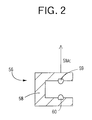
- FIG. 2 is a view for explaining a construction of a photoelectric-pulse-wave sensor shown in FIG. 1;
- FIG. 3 is a diagrammatic view for explaining essential control functions of an electronic control device of the inspecting apparatus of FIG. 1;
- FIG. 4 is a graph showing respective changes of an ankle pulse wave and a toe pulse wave that are detected when an ankle cuff pressure PC A is decreased by an ankle-cuff-pressure changing means shown in FIG. 3;
- FIG. 5 is a flow chart representing an ankle-blood-pressure determining routine as a portion of the essential control functions of the electronic control device, shown in FIG. 3;
- FIG. 6 is a flow chart representing an upper-arm-blood-pressure determining routine as another portion of the essential control functions of the electronic control device, shown in FIG. 3;
- FIG. 7 is a flow chart representing an ankle-upper-arm-blood-pressure-index (ABI) calculating routine as another portion of the essential control functions of the electronic control device, shown in FIG. 3;
- ABSI ankle-upper-arm-blood-pressure-index
- FIG. 8 is a view for explaining a construction of another arteriostenosis inspecting apparatus as a second embodiment of the present invention.
- FIG. 9 is a diagrammatic view for explaining essential control functions of an electronic control device of the inspecting apparatus of FIG. 8;
- FIG. 10 is a flow chart representing the essential control functions of the electronic control device, shown in FIG. 9;
- FIG. 11 is a diagrammatic view for explaining essential control functions of an electronic control device of another arteriostenosis inspecting apparatus as a third embodiment of the present invention.
- FIG. 12 is a flow chart representing the essential control functions of the electronic control device, shown in FIG. 11;
- FIG. 13 is a diagrammatic view for explaining essential control functions of an electronic control device of another arteriostenosis inspecting apparatus as a fourth embodiment of the present invention.
- FIG. 14 is a flow chart representing the essential control functions of the electronic control device, shown in FIG. 13 ;
- FIG. 1 is a view for explaining a construction of an arteriostenosis inspecting apparatus 10 to which the present invention is applied.
- the arteriostenosis inspecting apparatus 10 measures an ankle blood pressure BP(A) as a blood pressure BP of an ankle 12 of a patient as a living subject; measures an upper-arm blood pressure BP(B) as a blood pressure BP of an upper arm 14 of the patient; calculates, based on the thus measured ankle blood pressure BP(A) and upper-arm blood pressure BP(B), an ankle-upper-arm blood-pressure index ABI of the patient as an inferior-and-superior-limb blood-pressure index; and inspects, based on the thus calculated ankle-upper-arm blood-pressure index ABI, presence or absence of arteriostenosis of the subject.
- the arteriostenosis inspecting apparatus 10 includes an ankle-blood-pressure measuring device 16 which measures a blood pressure of the ankle 12 , and an upper-arm-blood-pressure measuring device 18 which measures a blood pressure of the upper arm 14 and functions as a superior-limb-blood-pressure measuring device.
- the ankle-blood-pressure measuring device 16 includes an ankle cuff 20 which includes a belt-like cloth bag and a rubber bag accommodated in the cloth bag and which is adapted to be wound around the ankle 12 of the patient; a pressure sensor 24 and a pressure control valve 26 which are connected to the ankle cuff 20 via a piping 22 ; and an air pump 28 which is connected to the pressure control valve 26 via a piping 27 .
- the pressure control valve 26 adjusts a pressure of a pressurized air supplied from the air pump 28 , and supplies the pressure-adjusted air to the ankle cuff 20 , or discharges the pressurized air from the ankle cuff 22 , so as to control an air pressure in the ankle cuff 20 .
- the pressure sensor 24 detects the air pressure in the ankle cuff 20 , and supplies a pressure signal, SP 1 , representing the detected air pressure, to a static-pressure filter circuit 30 and a pulse-wave filter circuit 32 .
- the static-pressure filter circuit 30 includes a low-pass filter which extracts, from the pressure signal SP 1 , an ankle-cuff-pressure signal, SC A , representing a static component of the detected air pressure, i.e., a pressing pressure of the ankle cuff 20 (hereinafter, referred to as the ankle cuff pressure, PC A ).
- the filter circuit 30 supplies the ankle-cuff-pressure signal SC A to an electronic control device 36 via an A/D (analog-to-digital) converter 34 .
- the pulse-wave filter circuit 32 includes a band-pass filter which extracts, from the pressure signal SP 1 , an ankle-pulse-wave signal, SM A , representing an ankle pulse wave as an oscillatory component of the detected air pressure that has prescribed frequencies.
- the filter circuit 32 supplies the ankle-pulse-wave signal SM A to the control device 36 via an A/D converter 38 . Since the ankle pulse wave indicates the oscillation of pressure of the ankle cuff 20 , the filter circuit 32 functions as an ankle-pulse-wave detecting device.
- the upper-arm-blood-pressure measuring device 18 includes an upper-arm cuff 40 , a pressure sensor 42 , a pressure control valve 46 , and an air pump 45 which have respective constructions identical with those of the counterparts of the ankle-blood-pressure measuring device 16 .
- the upper-arm cuff 40 is wound around the upper arm 14 .
- the pressure control valve 46 is connected to the air pump 45 via a piping 46 ; and the upper-arm cuff 40 is connected to the pressure sensor 42 and the pressure control valve 44 via a piping 47 .
- the pressure sensor 42 detects an air pressure in the upper-arm cuff 40 , and supplies a pressure signal, SP 2 , representing the detected air pressure, to a static-pressure filter circuit 48 and a pulse-wave filter circuit 50 which have respective constructions identical with those of the counterparts of the ankle-blood-pressure measuring device 16 .
- the static-pressure filter circuit 48 extracts, from the pressure signal SP 2 , an upper-arm-cuff-pressure signal, SC B , representing a static component of the detected air pressure, i.e., a pressing pressure of the upper-arm cuff 40 (hereinafter, referred to as the upper-arm-cuff pressure, PC B ).
- the filter circuit 48 supplies the upper-arm-cuff-pressure signal SC B to the control device 36 via an A/D converter 52 .
- the pulse-wave filter circuit 50 extracts, from the pressure signal SP 2 , an upper-arm-pulse-wave signal, SM B , representing an upper-arm pulse wave as an oscillatory component of the detected air pressure that has prescribed frequencies.
- the filter circuit 50 supplies the upper-arm-pulse-wave signal SM B to the control device 36 via an A/D converter 54 .
- a photoelectric-pulse-wave sensor 56 functioning as a distal-pulse-wave detecting device is worn on a toe of a foot of the patient, detects a volumetric pulse wave as change of volume of blood in capillaries of the toe, and outputs a volumetric-pulse-wave signal SM C representing the detected volumetric pulse wave, to the electronic control device 36 via an A/D converter 57 . Since the volumetric pulse wave represented by the volumetric-pulse-wave signal SM C is a pulse wave produced from the toe, it will be referred to as a toe pulse wave.
- the photoelectric-pulse-wave sensor 56 is worn on a distal portion of the patient that is located on a distal side of the ankle where the ankle cuff 20 is worn, the toe pulse wave detected by the sensor 56 is a distal pulse wave.
- FIG. 2 shows a construction of the photoelectric-pulse-wave sensor 56 .
- the sensor. 56 includes a housing 58 which can accommodate a body portion of the patient such as a toe; a light emitting element 59 which emits, toward the skin of the subject, a red or infrared light having a wavelength that can be reflected by hemoglobin, preferably, a light having a wavelength of about 800 nm that is not influenced by blood oxygen saturation; and a light detecting element 60 which is opposite to the light emitting element 59 and detects the light transmitted through the body portion of the subject.
- a housing 58 which can accommodate a body portion of the patient such as a toe
- a light emitting element 59 which emits, toward the skin of the subject, a red or infrared light having a wavelength that can be reflected by hemoglobin, preferably, a light having a wavelength of about 800 nm that is not influenced by blood oxygen saturation
- a light detecting element 60 which is
- the control device 36 is essentially provided by a microcomputer including a CPU (central processing unit) 62 , a ROM (read only memory) 64 , a RAM (random access memory) 66 , and an I/O (input-and-output) port, not shown, and the CPU 62 processes signals according to the programs pre-stored in the ROM 64 , while utilizing the data-storing function of the RAM 66 .
- the CPU 62 outputs, from the I/O port, drive signals to the air pumps 28 , 45 and the pressure control valves 26 , 44 so as to control the respective operations thereof and thereby control the respective air pressures of the ankle cuff 20 and the upper-arm cuff 40 .
- the CPU 62 processes signals supplied to the control device 36 , so as to determine an ankle blood pressure BP(A), an upper-arm blood pressure BP(B), and an ankle-and-upper-arm blood-pressure index ABI, and control a display device 68 to display the thus determined pressure and index values.
- FIG. 3 is a diagrammatic view for explaining essential control functions of the electronic control device 36 .
- An ankle-cuff-pressure changing device or means 70 controls, according to a command signal supplied from an ankle-blood-pressure determining means 78 , described later, and based on the ankle-cuff-pressure signal SC A supplied from the static-pressure filter circuit 30 , the air pump 28 and the pressure control valve 26 connected thereto, so as to change the ankle cuff pressure PC A , as follows: First, the changing means 70 quickly increases the ankle cuff pressure PC A UP to a prescribed first target pressure PC M1 (e.g., 240 mmHg) which would be higher than a systolic blood pressure BP(A) SYS of the ankle 12 , and subsequently slowly decreases the ankle cuff pressure PC A at a rate of about 3 mmHg/sec.
- a prescribed first target pressure PC M1 e.g., 240 mmHg
- the changing means 70 releases the ankle cuff pressure PC A to an atmospheric pressure.
- an ankle-cuff-pressure changing device is provided by the ankle-cuff-pressure changing means 70 ; the air pump 28 and the pressure control valve 26 that are controlled by the changing means 70 ; and the pressure sensor 24 and the static-pressure filter circuit 30 that cooperate with each other to supply the ankle cuff pressure PC A to the changing means 70 .
- a reference-pulse-wave-magnitude determining device or means 72 iteratively determines a reference pulse-wave magnitude with respect to a length of the toe pulse wave continuously detected by the photoelectric-pulse-wave sensor 56 while the ankle cuff pressure PC A is slowly decreased by the ankle-cuff-pressure changing means 70 , said length being detected in each time period that is so prescribed as to be equal to from one heartbeat of the subject to several heartbeats of the subject.
- the reference pulse-wave magnitude may be the average magnitude, the greatest magnitude, or the smallest magnitude of the length of the toe pulse wave detected in each prescribed time period.
- a change-value calculating device or means 74 calculates a change value (e.g., a rate of change or an amount of change) of each reference pulse-wave magnitude determined by the determining means 72 , from its preceding reference pulse-wave magnitude determined by the same 72 . Since the thus calculated change value is free from influences caused by the change of magnitude of toe pulse wave corresponding to each heartbeat of the subject, it accurately represents a change of flow amount of blood caused by the decreasing of pressure of the ankle cuff 20 .
- a change value e.g., a rate of change or an amount of change
- An increasing-point detecting device or means 76 calculates a rate of change of each change value determined by the change-value calculating means 74 from its preceding change value determined by the same 74 and detects a point where the thus calculated rate of change is greater than a prescribed reference value TH, as an increasing point, G, where the magnitude of toe pulse wave significantly increases.
- FIG. 4 illustratively shows respective changes of the ankle pulse wave and the toe pulse wave that are detected when the ankle cuff pressure PC A is decreased by the ankle-cuff-pressure changing means 70 .
- the second increasing point, G 2 is detected at a time, t2, shown in FIG. 4 .
- An ankle-blood-pressure determining device or means 78 determines change of the ankle cuff pressure PC A and change of respective amplitudes of successive heartbeat-synchronous pulses of the ankle pulse wave, based on the ankle-cuff-pressure signal SC A and the ankle-pulse-wave signal SM A that are continuously supplied from the static-pressure filter circuit 30 and the pulse-wave filter circuit 32 , respectively, when the ankle cuff pressure PC A is slowly decreased by the ankle-cuff-pressure changing means 70 , and additionally determines, according to a well-known oscillometric algorithm, blood-pressure values of the ankle 12 , i.e., an ankle systolic blood pressure BP(A) SYS , an ankle mean blood pressure BP(A) MEAN , and an ankle diastolic blood pressure BP(A) DIA .
- an ankle systolic blood pressure BP(A) SYS is determined as a value of the ankle cuff pressure PC A when the amplitude of the ankle pulse wave significantly increases, because the flow of blood in the ankle 12 resumes at that pressure value during the decreasing of the ankle cuff pressure PC A .
- the ankle-blood-pressure determining means 78 determines a value of the ankle cuff pressure PC A at the time of detection of the second increasing point G 2 , as a second ankle systolic blood pressure BP(A) SYS2 .
- An upper-arm-cuff-pressure changing device or means 80 controls, according to a command signal supplied from an upper-arm-blood-pressure determining means 82 , described later, and based on the upper-arm-cuff-pressure signal SC B supplied from the static-pressure filter circuit 50 , the air pump 45 and the pressure control valve 44 connected thereto, so as to change the upper-arm cuff pressure PCB, as follows: First, the changing means 80 quickly increases the upper-arm cuff pressure PC B UP to a prescribed second target pressure PC M2 (e.g., 180 mmHg) which would be higher than a systolic blood pressure BP(A) SYS of the upper arm 14 , and subsequently slowly decreases the upper-arm cuff pressure PC B at a rate of about 3 mmHg/sec. Finally, after determination of a diastolic blood pressure BP(B) DIA of the upper arm, the changing means 80 releases the upper-arm cuff pressure PC B to an atmospheric pressure.
- An upper-arm-blood-pressure determining device or means 82 determines change of the upper-arm cuff pressure PCB and change of respective amplitudes of successive heartbeat-synchronous pulses of the upper-arm pulse wave, based on the upper-arm-cuff-pressure signal SC B and the upper-arm-pulse-wave signal SM B that are continuously supplied from the static-pressure filter circuit 48 and the pulse-wave filter circuit 50 , respectively, when the upper-arm cuff pressure PC B is slowly decreased by the upper-arm-cuff-pressure changing means 80 , and additionally determines, according to the well-known oscillometric algorithm, blood-pressure values of the upper arm 14 , i.e., an upper-arm systolic blood pressure BP(B) SYS , an upper-arm mean blood pressure BP(B) MEAN , and an upper-arm diastolic blood pressure BP(B) DIA .
- An inferior-and-superior-limb-blood-pressure-index determining device or means 84 determines, if the ankle-blood-pressure determining means 78 has determined the second ankle systolic blood pressure BP(A) SYS2 , an ankle-and-upper-arm blood-pressure index ABI of the subject, based on the second ankle systolic blood pressure BP(A) SYS2 and the upper-arm systolic blood pressure BP(B) SYS determined by the upper-arm-blood-pressure determining means 82 and, if not, determines an ankle-and-upper-arm blood-pressure index ABI of the subject, based on the ankle systolic blood pressure BP(A) SYS determined by the ankle-blood-pressure determining means 78 and the upper-arm systolic blood pressure BP(B) SYS determined by the upper-arm-blood-pressure determining means 82 .
- an ankle-and-upper-arm blood-pressure index ABI is obtained by dividing the second ankle systolic blood pressure BP(A) SYS2 or the ankle systolic blood pressure BP(A) SYS by the upper-arm systolic blood pressure BP(B) SYS , or dividing the upper-arm systolic blood pressure BP(B) SYS by the second ankle systolic blood pressure BP(A) SYS2 or the ankle systolic blood pressure BP(A) SYS .
- FIGS. 5 through 7 show respective charts representing the essential control functions of the electronic control device 36 , shown in FIG. 3 .
- FIG. 5 shows an ankle-blood-pressure determining routine
- FIG. 6 shows an upper-arm-blood-pressure determining routine
- FIG. 7 shows an ankle-and-upper-arm-blood-pressure-index (ABI) determining routine.
- ABSI ankle-and-upper-arm-blood-pressure-index
- Step SA 1 (hereinafter, “Step” is omitted) to control the air pump 28 and the pressure control valve 26 so as to start quick increasing of the ankle cuff pressure PC A .
- Step 2 the control device judges whether the ankle cuff pressure PC A has been increased up to the first target pressure PC M1 , e.g., 240 mmHg. Step SA 2 is repeated till a positive judgment is made.
- the control goes to SA 3 to stop the air pump 28 and controls the pressure control valve 26 so as to start slow decreasing of the ankle cuff pressure PC A , e.g., at a prescribed rate of 3 mmHg/sec.
- the control device carries out a blood-pressure determining routine. More specifically described, the control device determines, based on the ankle-cuff-pressure signal SC A and the ankle-pulse-wave signal SM A read in at SA 5 , respective values of the ankle cuff pressure PC A and respective amplitudes of successive heartbeat-synchronous pulses of the ankle pulse wave, and determines, based on the thus determined respective values of the ankle cuff pressure PC A and the thus determined respective amplitudes of successive heartbeat-synchronous pulses of the ankle pulse wave, an ankle systolic blood pressure BP(A) SYS , an ankle mean blood pressure BP(A) MEAN , and an ankle diastolic blood pressure BP(A) DIA of the subject, according to a well-known oscillometric blood-pressure-determination algorithm.
- the control device judges whether the time measured by the timer t has exceeded a time period, T1, that is pre-set at a time duration corresponding to one heartbeat of the subject. If a negative judgment is made at SA 7 , the control goes back to SA 5 and the following steps, so as to continue reading in the ankle-cuff-pressure signal SC A , the ankle-pulse-wave signal SM A , and the volumetric-pulse-wave signal SM C , and continue carrying out the blood-pressure determining routine based on the thus read-in signals.
- the control goes to SA 8 corresponding to the reference-pulse-wave-magnitude determining means 72 .
- the control device calculates an average magnitude of the length of the toe pulse wave which length has been read in during the time period T1 while SA 5 through SA 7 are repeated.
- the control device divides the current average magnitude calculated at SA 8 in the current control cycle according to the ankle-blood-pressure determining routine, by the preceding average magnitude calculated at SA 8 in the preceding control cycle according to the same routine, and thereby obtains a rate of change of the current average magnitude.
- SA 9 corresponds to the change-value determining means 74 .
- the control device judges whether the rate of change determined at SA 9 is greater than a reference value TH that is experimentally determined in advance.
- a positive judgment made at SA 10 means that the average magnitude of each length of the toe pulse wave, detected during the time period T1, has significantly increased, i.e., that an increasing point G has occurred. Thus, a positive judgment made at SA 10 means that an increasing point G has been detected.
- a positive judgment is made at SA 10 , at the time t1 or at the time t2.
- SA 10 If a negative judgment is made at SA 10 , the control jumps to SA 13 . On the other hand, if a positive judgment is made at SA 10 , the control goes to SA 11 to judge whether the increasing point G detected at SA 10 is the second increasing point G 2 . A positive judgment made at SA 11 means that the flow of blood resumes in one of the anterior and posterior tibial arteries that has the lower systolic blood pressure.
- the control goes to SA 12 to determine the current value of the ankle cuff pressure PC A , i.e., the value of the ankle cuff pressure PC A represented by the ankle-cuff-pressure signal SC A read in at SA 5 in the current control cycle, as a second ankle systolic blood pressure BP(A) SYS2 .
- the first increasing point G 1 is detected at SA 10 , at the time t1 shown in FIG. 4, and, based on the first increasing point, the ankle systolic blood pressure BP(A) SYS is determined at SA 6 . Therefore, the second ankle systolic blood pressure BP(A) SYS2 is the lower one of the respective systolic blood pressure of the anterior and posterior tibial arteries that is caused by stenosis.
- the control goes to SA 14 so as to operate the display device 68 to display the ankle systolic blood pressure BP(A) SYS , the ankle mean blood pressure BP(A) MEAN , and the ankle diastolic blood pressure BP(A) DIA .
- the control device controls the pressure control valve 26 to release the ankle cuff pressure PC A to an atmospheric pressure, thereby finishing the pressing of the ankle 12 with the ankle cuff 20 .
- SA 1 through SA 3 and SA 15 correspond to the ankle-cuff-pressure changing means 70 .
- the upper-arm-blood-pressure determining routine may be carried out concurrently with the ankle-blood-pressure determining routine of FIG. 5, on an interruption or time-sharing basis, or may be carried out immediately before or after the routine of FIG. 5 is carried out.
- the control device controls the air pump 45 and the pressure control valve 44 so as to start quick increasing of the upper-arm cuff pressure PCB.
- the control device judges whether the upper-arm cuff pressure PC B has been increased up to the second target pressure PC M2 , e.g., 180 mmHg. Step SB 2 is repeated till a positive judgment is made. Meanwhile, if a positive judgment is made at SB 2 , the control goes to SB 3 to stop the air pump 45 and control the pressure control valve 44 so as to start slow decreasing of the upper-arm cuff pressure PCB, e.g., at a prescribed rate of about 3 mmHg/sec.
- the control device reads in the upper-arm-cuff-pressure signal SC B supplied from the static-pressure filter circuit 48 , and the upper-arm-pulse-wave signal SM B supplied from the pulse-wave filter circuit 50 .
- the control device carries out the same blood-pressure determining routine as that employed at SA 6 of FIG. 5, so as to determine an upper-arm systolic blood pressure BP(B) SYS , an upper-arm mean blood pressure BP(B) MEAN , and an upper-arm diastolic blood pressure BP(B) DIA of the subject.
- the control device judges whether the determination of upper-arm blood-pressure values at SB 5 has been completed, i.e., whether all the upper-arm systolic blood pressure BP(B) SYS , upper-arm mean blood pressure BP(B) MEAN , and upper-arm diastolic blood pressure BP(B) DIA have been determined. If a negative judgment is made at SB 6 , the control goes back to SB 4 and the following steps so as to further read in the upper-arm cuff-pressure signal SC B and the upper-arm-pulse-wave signal SM B , and continue carrying out the blood-pressure determining routine.
- SB 5 and SB 6 correspond to the upper-arm-blood-pressure determining means 82 .
- SB 6 if a positive judgment is made at SB 6 , the control goes to SB 7 so as to operate the display device 68 to display the upper-arm systolic blood pressure BP(B) SYS , the upper-arm mean blood pressure BP(B) MEAN , and the upper-arm diastolic blood pressure BP(B) DIA .
- the control device controls the pressure control valve 44 to release the upper-arm cuff pressure PC B to an atmospheric pressure, thereby finishing the pressing of the upper arm 14 with the upper-arm cuff 40 .
- SB 1 through SB 3 and SB 8 correspond to the upper-arm-cuff-pressure changing means 80 .
- the ankle-and-upper-arm-blood-pressure-index (ABI) determining routine of FIG. 7 corresponds to the inferior-and-superior-limb-blood-pressure-index determining means 84 .
- the control device judges whether, in the ankle-blood-pressure determining routine of FIG. 5, the second ankle systolic blood pressure BP(A) SYS2 has been determined. If a positive judgment is made at SC 1 , the control goes to SC 2 to calculate an ankle-upper-arm blood-pressure index ABI by dividing the second ankle systolic blood pressure BP(A) SYS2 by the upper-arm systolic blood pressure BP(B) SYS .
- the control goes to SC 3 to calculate an ankle-upper-arm blood-pressure index ABI by dividing the ankle systolic blood pressure BP(A) SYS by the upper-arm systolic blood pressure BP(B) SYS . Then, at SC 4 , the control device operates the display device 68 to display the ankle-upper-arm blood-pressure index ABI calculated at SC 2 or SC 3 .
- the photoelectric-pulse-wave sensor 56 worn on the toe corresponding to the ankle 12 on which the ankle cuff 20 is worn continuously detects the toe pulse wave.
- the control device determines an average magnitude of the toe pulse wave detected during each time period T1; at SA 9 (the change-value calculating means 74 ), the control device calculates a rate of change of each average magnitude; and at SA 10 (the increasing-point detecting means 76 ), the control device detects, based on the thus calculated rate-of-change values, an increasing point G where the magnitude of the toe pulse wave significantly increases.
- the control device detects, at SA 10 (the increasing-point detecting means 76 ), detects two increasing points G and accordingly the control device determines, at SA 12 (the ankle-blood-pressure determining means 78 ), an ankle cuff pressure PC A when the control device detects, at SA 10 (the increasing-point detecting means 76 ), detects the second increasing point G 2 , as a systolic blood pressure of the stenotic tibial artery, i.e., a second systolic blood pressure BP(A) SYS2 .
- the control device calculates, at SC 1 through SC 4 (the inferior-and-superior-limb blood-pressure index determining means 84 ), an inferior-and-superior-limb blood-pressure index ABI of the subject based on the systolic blood pressure of the stenotic tibial artery, i.e., the second systolic blood pressure BP(A) SYS2 , measured by the ankle-blood-pressure measuring device 16 . Based on the thus determined index ABI, a medical person can accurately judge whether the subject has arteriostenosis.
- FIG. 8 is a view for explaining a construction of another arteriostenosis inspecting apparatus 90 as the second embodiment.
- the arteriostenosis inspecting apparatus 90 shown in FIG. 8 differs from the apparatus 10 shown in FIG. 1, in that the apparatus 90 does not employ the upper-arm-blood-pressure measuring device 18 .
- FIG. 9 is a diagrammatic view for explaining essential control functions of an electronic control device 36 of the arteriostenosis inspecting apparatus 90 .
- An ankle-cuff-pressure changing device or means 92 controls, based on the ankle-cuff pressure signal SC A supplied from the static-pressure filter circuit 30 , the air pump 28 and the pressure control valve 26 connected thereto, so as to quickly increase the ankle cuff pressure PC A UP to the prescribed first target pressure PC M1 (e.g., 240 mmHg) which would be higher than the systolic blood pressure BP(A) SYS of the ankle 12 , and subsequently slowly decrease the ankle cuff pressure PC A at the rate of about 3 mmHg/sec.
- the prescribed first target pressure PC M1 e.g., 240 mmHg
- the third target pressure PC M3 is so prescribed as to be lower than the ankle systolic blood pressure BP(A) SYS even if the systolic blood pressure BP(A) SYS may be lowered by the presence of arteriostenosis.
- a reference-pulse-wave-magnitude determining device or means 72 , a change-value calculating device or means 74 , and an increasing-point detecting device or means 76 of the arteriostenosis inspecting apparatus 90 are identical with the counterparts 72 , 74 , 76 of the apparatus 10 . Therefore, the increasing-point detecting means 76 detects an increasing point G where the magnitude of the toe pulse wave continuously detected by the photoelectric-pulse-wave sensor 56 significantly increases.
- An arteriostenosis judging device or means 94 judges that the subject has arteriostenosis based on a fact that the increasing-point detecting means 76 has detected the second increasing point G 2 , and operates the display device 68 to display characters or symbols indicating that the subject has arteriostenosis.
- a waveform displaying device or means 96 operates the display device 68 to display, with a time-wise change of the ankle cuff pressure PC A , respective waveforms of the ankle pulse wave and the toe pulse wave that are continuously detected by the pulse-wave filter circuit 32 and the photoelectric-pulse-wave sensor 56 , respectively, when the ankle cuff pressure PC A is slowly decreased by the ankle-cuff-pressure changing means 92 .
- FIG. 4 shows the ankle cuff pressure PC A , the ankle pulse wave, and the toe pulse wave that are displayed by the waveform displaying means 96 .
- FIG. 10 shows a flow chart representing the essential control functions of the electronic control device 36 , shown in FIG. 9 .
- SD 1 through SD 5 shown in FIG. 10 are identical with SA 1 through SA 5 shown in FIG. 5 .
- the control device operates the display device 68 to display the ankle cuff pressure PC A , the ankle pulse wave, and the toe pulse wave, based on the ankle-cuff-pressure signal SC A , the ankle-pulse-wave signal SM A , and the volumetric-pulse-wave signal SM C , each read in at SD 5 , respectively.
- SD 7 through SD 11 are identical with SA 7 through SA 11 shown in FIG. 5 .
- the control device judges whether the rate-of-change values iteratively calculated at SD 9 have exceeded the reference value TH for the second time.
- a positive judgment made at SD 11 means that the anterior tibial artery or the posterior tibial artery has stenosis. Therefore, the control goes to SD 12 to operate the display device 68 to display an indication, “SUBJECT HAS ARTERIOSTENOSIS”.
- SD 11 and SD 12 correspond to the arteriostenosis judging means 94 .
- SD 10 or SD 11 If a negative judgment is made at SD 10 or SD 11 , or after SD 12 is carried out, then the control goes to SD 13 to judge whether the ankle cuff pressure PC A has been decreased down to a third target pressure PC M3 , e.g., 90 mmHg. If a negative judgment is made at SD 13 , the control goes back to SD 4 and the following steps, so that while the ankle cuff pressure PC A is slowly decreased, the control device continues displaying the pulse waves and detecting the increasing points G. On the other hand, if a positive judgment is made at SD 13 , the control goes to SD 14 to operate the pressure control valve 26 to release the ankle cuff pressure PC A down to an atmospheric pressure, thereby ending the pressing of the ankle 12 with the ankle cuff 20 . In the embodiment shown in FIG. 10, SD 1 through SD 3 , SD 13 and SD 14 correspond to the ankle-cuff-pressure changing means 92 .
- the control device determines an average magnitude of the toe pulse wave detected during each time period T1; at SD 9 (the change-value calculating means 74 ), the control device calculates a rate of change of each average magnitude; and at SD 10 (the increasing-point detecting means 76 ), the control device detects, based on the thus calculated rate-of-change values, an increasing point G where the magnitude of the toe pulse wave significantly increases.
- the control device detects, at SD 10 (the increasing-point detecting means 76 ), detects two increasing points G. Therefore, at SD 11 (the arteriostenosis judging means 94 ), the control device judges that the subject has arteriostenosis, based on a fact that the control device has detected, at SD 10 (the increasing-point detecting means 76 ), detects the second increasing point G 2 .
- the photoelectric-pulse-wave sensor 56 worn on the toe corresponding to the ankle 12 on which the ankle cuff 20 is worn continuously detects the toe pulse wave.
- the thus detected toe pulse wave is displayed by the display device 68 . If the toe pulse wave displayed by the display device 68 has two increasing points G at each of which the magnitude of the pulse wave significantly increases, a medical person can judge that even if one of the two tibial arteries may not have stenosis, the other tibial artery has stenosis.
- FIG. 11 is a diagrammatic view for explaining essential control functions of the electronic control device 36 of the arteriostenosis inspecting apparatus as the third embodiment.
- An ankle-cuff-pressure changing device or means 100 changes and keeps the ankle cuff pressure PC A to and at a pulse-wave detection pressure.
- the pulse-wave detection pressure is so prescribed as to be lower than a diastolic blood pressure of the ankle where the ankle cuff 20 is worn, and assure that an ankle-pulse-wave signal SM A extracted by the pulse-wave filter circuit 32 has a sufficiently great magnitude.
- the pulse-wave detection pressure is prescribed at 50 mmHg.
- an ankle-cuff-pressure changing device is provided by the ankle-cuff-pressure changing means 100 ; the air pump 28 and the pressure control valve 26 that are controlled by the changing means 100 ; and the pressure sensor 24 and the static-pressure filter circuit 30 that cooperate with each other to supply the ankle-cuff-pressure signal SC A to the changing means 100 .
- An amplitude-difference-value determining device or means 102 first determines respective amplitudes of respective heartbeat-synchronous pulses of the ankle pulse wave and the toe pulse wave respectively represented by the ankle-pulse-wave signal SM A and the volumetric-pulse-wave signal SM C that are supplied from the pulse-wave filter circuit 32 and the photoelectric-pulse-wave sensor 56 , respectively, in the state in which the ankle cuff pressure PC A is kept at the pulse-wave detection pressure by the ankle-cuff-pressure changing means 100 . Then, the amplitude-difference determining means 102 determines an amplitude difference value indicating a degree of difference between the thus determined two amplitudes.
- the amplitude difference value may be a value obtained by subtracting one of the two amplitudes from the other amplitude, or a value obtained by dividing one of the two amplitudes by the other amplitude.
- the amplitude of the toe pulse wave detected from the toe is smaller than that of the ankle pulse wave detected from the ankle. If there is arteriostenosis between the ankle 12 and the toe, the amplitude of the toe pulse wave is much smaller than that of the ankle pulse wave. Therefore, the amplitude difference value is increased by the presence of arteriostenosis.
- an arteriostenosis judging device or means 104 judges that the subject has arteriostenosis between the ankle where the cuff is worn and the toe where the photoelectric-pulse-wave sensor 56 is worn, and operates the display device 68 to display this judgment.
- FIG. 12 shows a flow chart representing the essential control functions of the electronic control device 36 , shown in FIG. 11 .
- the control device operates the air pump 28 and the pressure control valve 26 so as to change the ankle cuff pressure PC A to a pulse-wave detection pressure, e.g., 50 mmHg, and then stops the air pump 28 and closes the pressure control valve 26 so as to keep the ankle cuff pressure PC A at the pulse-wave detection pressure.
- a pulse-wave detection pressure e.g., 50 mmHg
- the control device reads in respective one-heartbeat lengths of the ankle-pulse-wave signal SM A and the volumetric-pulse-wave signal SM C in the state in which the ankle cuff pressure PC A is kept at the pulse-wave detection pressure. Subsequently, at SE 3 , the control device operates the pressure control valve 26 to release the ankle cuff pressure PC A to an atmospheric pressure.
- the control goes to SE 4 corresponding to the amplitude-difference-value determining means 102 .
- the control device determines, based on the respective one-heartbeat lengths of the ankle-pulse-wave signal SM A and the volumetric-pulse-wave signal SM C read in at SE 2 , respective amplitudes of respective heartbeat-synchronous pulses of the ankle pulse wave and the toe pulse wave, and additionally determines an amplitude difference by subtracting the amplitude of the toe pulse wave from that of the ankle pulse wave.
- the control goes to SE 5 and SE 6 corresponding to the arteriostenosis judging means 104 .
- SE 5 the control device judges whether the amplitude difference determined at SE 4 is greater than a prescribed reference value. If yes, the control device judges that the subject has arteriostenosis; and if no, the control device judges that the subject does not have arteriostenosis. Then, at SE 6 , the control device operates the display device 68 to display the judgment made at SE 5 .
- the ankle cuff pressure PC A in the state in which the ankle cuff pressure PC A is kept at the pulse-wave detection pressure at SE 1 (the cuff-pressure changing means 100 ), the ankle pulse wave and the distal pulse wave are detected at SE 2 , and the amplitude difference between the respective amplitudes of the ankle pulse wave and the distal pulse wave is determined at SE 4 (the amplitude-difference-value determining means 102 ).
- the control device judges, at SE 5 (the arteriostenosis judging means 104 ), whether the subject has arteriostenosis between the ankle where the ankle cuff 20 is worn and the toe where the photoelectric-pulse-wave sensor 56 is worn.
- FIG. 13 is a diagrammatic view for explaining essential control functions of the electronic control device 36 of the arteriostenosis inspecting apparatus as the fourth embodiment.
- FIG. 13 differs from that shown in FIG. 11 only in that in FIG. 13 a phase-difference determining device or means 106 is provided in place of the amplitude-difference-value determining means 102 provided in FIG. 11 and in that an arteriostenosis judging device or means 108 provided in FIG. 13 makes a judgment based on a phase difference determined by the phase-difference determining means 106 .
- a phase-difference determining device or means 106 is provided in place of the amplitude-difference-value determining means 102 provided in FIG. 11 and in that an arteriostenosis judging device or means 108 provided in FIG. 13 makes a judgment based on a phase difference determined by the phase-difference determining means 106 .
- the phase-difference determining means 106 determines a difference between respective phases of respective heartbeat-synchronous pulses of the ankle pulse wave and the toe pulse wave respectively represented by the ankle-pulse-wave signal SM A and the volumetric-pulse-wave signal SM C that are supplied from the pulse-wave filter circuit 32 and the photoelectric-pulse-wave sensor 56 , respectively, in the state in which the ankle cuff pressure PC A is kept at the pulse-wave detection pressure by the ankle-cuff-pressure changing means 100 . If there is arteriostenosis between the ankle 12 and the toe, the phase of the toe pulse wave detected from the toe is delayed from that of the ankle pulse wave detected from the ankle. Therefore, the phase difference is increased by the presence of arteriostenosis.
- an arteriostenosis judging device or means 108 judges that the subject has arteriostenosis between the ankle where the cuff is worn and the toe where the photoelectric-pulse-wave sensor 56 ; is worn, and operates the display device 68 to display this judgment.
- FIG. 14 shows a flow chart representing the essential control functions of the electronic control device 36 , shown in FIG. 13 .
- SF 1 through SF 3 shown in FIG. 14 are identical with SE 1 through SE 3 shown in FIG. 12 .
- the control device reads in respective one-heartbeat lengths of the ankle-pulse-wave signal SM A and the volumetric-pulse-wave signal SM C and, subsequently at SE 3 , the control device operates the pressure control valve 26 to release the ankle cuff pressure PC A to an atmospheric pressure.
- the control goes to SF 4 corresponding to the phase-difference determining means 106 .
- the control device determines, based on the respective one-heartbeat lengths of the ankle-pulse-wave signal SM A and the volumetric-pulse-wave signal SM C read in at SE 2 , respective phases of respective heartbeat-synchronous pulses of the ankle pulse wave and the toe pulse wave, and additionally determines a phase difference by subtracting the phase of the toe pulse wave from that of the ankle pulse wave.
- the control goes to SF 5 and SF 6 corresponding to the arteriostenosis judging means 108 .
- the control device judges whether the phase difference determined at SF 4 is greater than a prescribed reference value. If yes, the control device judges that the subject has arteriostenosis; and if no, the control device judges that the subject does not have arteriostenosis. Then, at SF 6 , the control device operates the display device 68 to display the judgment made at SF 5 .
- the ankle cuff pressure PC A in the state in which the ankle cuff pressure PC A is kept at the pulse-wave detection pressure at SF 1 (the cuff-pressure changing means 100 ), the ankle pulse wave and the distal pulse wave are detected at SF 2 , and the phase difference between the respective phases of the ankle pulse wave and the distal pulse wave is determined at SF 4 (the phase-difference determining means 106 ).
- the control device judges, at SF 5 (the arteriostenosis judging means 108 ), whether the subject has arteriostenosis between the ankle where the ankle cuff 20 is worn and the toe where the photoelectric-pulse-wave sensor 56 is worn.
- the photoelectric-pulse-wave sensor 56 is worn on a toe of foot.
- the sensor 56 may be worn on any distal portion located on a distal side of the ankle cuff 20 , for example, a proximal portion located on a proximal side of a toe, such as an instep (i.e., a portion above a dorsal pedal artery).
- the ankle pulse wave and the toe pulse wave are detected in the state in which the ankle cuff pressure PC A is kept at the pulse-wave detection pressure.
- the ankle pulse wave and the toe pulse wave may be detected in a state in which the ankle cuff pressure PC A is slowly decreased.
Abstract
Description
Claims (4)
Priority Applications (1)
| Application Number | Priority Date | Filing Date | Title |
|---|---|---|---|
| US10/781,732 US6923771B2 (en) | 2002-05-07 | 2004-02-20 | Arteriostenosis inspecting apparatus and ankle-blood-pressure measuring apparatus |
Applications Claiming Priority (2)
| Application Number | Priority Date | Filing Date | Title |
|---|---|---|---|
| JP2002-131848 | 2002-05-07 | ||
| JP2002131848A JP3623488B2 (en) | 2002-05-07 | 2002-05-07 | Arterial stenosis inspection device and ankle blood pressure measurement device |
Related Child Applications (1)
| Application Number | Title | Priority Date | Filing Date |
|---|---|---|---|
| US10/781,732 Division US6923771B2 (en) | 2002-05-07 | 2004-02-20 | Arteriostenosis inspecting apparatus and ankle-blood-pressure measuring apparatus |
Publications (2)
| Publication Number | Publication Date |
|---|---|
| US20030212334A1 US20030212334A1 (en) | 2003-11-13 |
| US6796946B2 true US6796946B2 (en) | 2004-09-28 |
Family
ID=29397361
Family Applications (2)
| Application Number | Title | Priority Date | Filing Date |
|---|---|---|---|
| US10/370,503 Expired - Fee Related US6796946B2 (en) | 2002-05-07 | 2003-02-24 | Arteriostenosis inspecting apparatus and ankle-blood-pressure measuring apparatus |
| US10/781,732 Expired - Fee Related US6923771B2 (en) | 2002-05-07 | 2004-02-20 | Arteriostenosis inspecting apparatus and ankle-blood-pressure measuring apparatus |
Family Applications After (1)
| Application Number | Title | Priority Date | Filing Date |
|---|---|---|---|
| US10/781,732 Expired - Fee Related US6923771B2 (en) | 2002-05-07 | 2004-02-20 | Arteriostenosis inspecting apparatus and ankle-blood-pressure measuring apparatus |
Country Status (6)
| Country | Link |
|---|---|
| US (2) | US6796946B2 (en) |
| EP (1) | EP1366708A3 (en) |
| JP (1) | JP3623488B2 (en) |
| KR (1) | KR100865647B1 (en) |
| CN (1) | CN100453034C (en) |
| TW (1) | TWI289440B (en) |
Cited By (14)
| Publication number | Priority date | Publication date | Assignee | Title |
|---|---|---|---|---|
| US20060195034A1 (en) * | 2003-04-01 | 2006-08-31 | Falko Skrabal | Device and method for the continuous non-invasive measurement of blood pressure |
| US20090099465A1 (en) * | 2007-10-15 | 2009-04-16 | Summit Doppler Systems, Inc. | System and method for a non-supine extremity blood pressure ratio examination |
| US7809420B2 (en) | 2003-06-25 | 2010-10-05 | Nellcor Puritan Bennett Llc | Hat-based oximeter sensor |
| US7822453B2 (en) | 2002-10-01 | 2010-10-26 | Nellcor Puritan Bennett Llc | Forehead sensor placement |
| US8257274B2 (en) | 2008-09-25 | 2012-09-04 | Nellcor Puritan Bennett Llc | Medical sensor and technique for using the same |
| US8364220B2 (en) | 2008-09-25 | 2013-01-29 | Covidien Lp | Medical sensor and technique for using the same |
| US8412297B2 (en) | 2003-10-01 | 2013-04-02 | Covidien Lp | Forehead sensor placement |
| US8515515B2 (en) | 2009-03-25 | 2013-08-20 | Covidien Lp | Medical sensor with compressible light barrier and technique for using the same |
| US8781548B2 (en) | 2009-03-31 | 2014-07-15 | Covidien Lp | Medical sensor with flexible components and technique for using the same |
| US9101274B2 (en) | 2010-06-24 | 2015-08-11 | Cvr Global, Inc. | Sensor, sensor pad and sensor array for detecting infrasonic acoustic signals |
| US9211070B2 (en) | 2010-09-23 | 2015-12-15 | Cleveland Clinic Foundation | Evaluation of peripheral arterial disease in a patient using an oscillometric pressure signal obtained at a lower extremity of the patient |
| US9324035B2 (en) | 2012-03-15 | 2016-04-26 | Samsung Electronics Co., Ltd. | Apparatus and method for predicting potential change of coronary artery calcification (CAC) level |
| US9375150B2 (en) | 2012-04-25 | 2016-06-28 | Summit Doppler Systems, Inc. | Identification of pressure cuff conditions using frequency content of an oscillometric pressure signal |
| US11413653B2 (en) | 2010-06-24 | 2022-08-16 | Cvr Global, Inc. | Sensor, sensor pad and sensor array for detecting infrasonic acoustic signals |
Families Citing this family (14)
| Publication number | Priority date | Publication date | Assignee | Title |
|---|---|---|---|---|
| US7214192B2 (en) * | 2004-09-07 | 2007-05-08 | Biomedix, Inc. | Vascular testing system |
| US7172555B2 (en) * | 2004-09-07 | 2007-02-06 | Biomedix, Inc. | Vascular testing system |
| US7166076B2 (en) * | 2004-09-07 | 2007-01-23 | Biomedix, Inc. | Vascular testing system |
| JP5147700B2 (en) * | 2005-09-06 | 2013-02-20 | ヴァサメッド インコーポレイテッド | System for automatic measurement of skin perfusion pressure |
| JP4879038B2 (en) * | 2007-02-05 | 2012-02-15 | 株式会社エー・アンド・デイ | Blood pressure measurement device capable of pulse wave detection |
| US8636670B2 (en) | 2008-05-13 | 2014-01-28 | The Invention Science Fund I, Llc | Circulatory monitoring systems and methods |
| US9717896B2 (en) | 2007-12-18 | 2017-08-01 | Gearbox, Llc | Treatment indications informed by a priori implant information |
| US20090287120A1 (en) | 2007-12-18 | 2009-11-19 | Searete Llc, A Limited Liability Corporation Of The State Of Delaware | Circulatory monitoring systems and methods |
| KR101010576B1 (en) * | 2008-03-27 | 2011-01-24 | 한경희 | Mounting structure of duct for garbage dryer |
| KR101069489B1 (en) | 2009-04-30 | 2011-09-30 | 연세대학교 산학협력단 | Evaluation apparatus of peripheral blood vessel and blood flow state and method thereof |
| CN102078226B (en) * | 2011-03-11 | 2011-12-14 | 冯振花 | Decompression assist device for cardiac aortic stenosis or incompetence |
| CN104783771B (en) * | 2015-05-08 | 2017-10-27 | 青岛大学附属医院 | The postoperative strong and weak monitoring device of artery of lower extremity beating of femoral artery puncture |
| CN107174197B (en) * | 2016-03-10 | 2020-11-24 | 深圳市理邦精密仪器股份有限公司 | Monitoring equipment and waveform display method and device thereof |
| CN110613438A (en) * | 2018-06-19 | 2019-12-27 | 信锦企业股份有限公司 | Control method of sphygmomanometer group |
Citations (8)
| Publication number | Priority date | Publication date | Assignee | Title |
|---|---|---|---|---|
| US4437470A (en) | 1979-08-28 | 1984-03-20 | Battelle Memorial Institute | Process and apparatus for measuring blood pressure |
| US5791348A (en) * | 1991-03-01 | 1998-08-11 | Colin Electronics Co., Ltd. | Automatic blood pressure measuring system |
| EP0891740A1 (en) | 1997-07-18 | 1999-01-20 | Citizen Watch Co., Ltd. | Oscillometric type electronic sphygmomanometer |
| EP1080685A1 (en) | 1999-09-06 | 2001-03-07 | Colin Corporation | Blood-pressure measuring apparatus |
| US6283922B1 (en) * | 1996-10-24 | 2001-09-04 | Colin Corporation | Blood pressure monitor |
| US20020026120A1 (en) | 1999-05-17 | 2002-02-28 | Colin Corporation | Superior-and-inferior-limb blood-pressure index measuring apparatus and inferior-limb blood-pressure measuring apparatus |
| US6355000B1 (en) | 1999-05-06 | 2002-03-12 | Colin Corporation | Superior-and-inferior-limb blood-pressure index measuring apparatus |
| WO2002024053A2 (en) | 2000-09-21 | 2002-03-28 | Virginia Commonwealth University | Monitoring central venous pressures and intravascular volume |
Family Cites Families (9)
| Publication number | Priority date | Publication date | Assignee | Title |
|---|---|---|---|---|
| GB8401500D0 (en) * | 1984-01-20 | 1984-02-22 | Johnson Matthey Plc | Measurement of physiological parameter |
| ATE134852T1 (en) * | 1991-01-31 | 1996-03-15 | Sankyo Co | MEASURING THE TRANSMISSION SPEED OF THE PULSE WAVE |
| CN1063404A (en) * | 1991-06-27 | 1992-08-12 | 张建忠 | Nonintrusive testing method for conpensation of coronary artery |
| JP3184349B2 (en) * | 1992-12-25 | 2001-07-09 | フクダ電子株式会社 | Peripheral arteriosclerosis index measuring device |
| JP3147584B2 (en) * | 1993-05-13 | 2001-03-19 | オムロン株式会社 | Electronic sphygmomanometer |
| US5368039A (en) * | 1993-07-26 | 1994-11-29 | Moses; John A. | Method and apparatus for determining blood pressure |
| JP2001286521A (en) * | 2000-04-10 | 2001-10-16 | Nippon Colin Co Ltd | Vein thrombus embolism preventing device |
| JP4395993B2 (en) * | 2000-05-30 | 2010-01-13 | オムロンヘルスケア株式会社 | Lower limb upper limb blood pressure index measuring device |
| DE10043015C2 (en) * | 2000-09-01 | 2002-09-19 | Walter Ag | Cutting tool with direct insert system |
-
2002
- 2002-05-07 JP JP2002131848A patent/JP3623488B2/en not_active Expired - Fee Related
-
2003
- 2003-02-24 TW TW092103795A patent/TWI289440B/en not_active IP Right Cessation
- 2003-02-24 US US10/370,503 patent/US6796946B2/en not_active Expired - Fee Related
- 2003-03-28 EP EP03007156A patent/EP1366708A3/en not_active Withdrawn
- 2003-04-18 KR KR1020030024604A patent/KR100865647B1/en not_active IP Right Cessation
- 2003-05-07 CN CNB031307205A patent/CN100453034C/en not_active Expired - Fee Related
-
2004
- 2004-02-20 US US10/781,732 patent/US6923771B2/en not_active Expired - Fee Related
Patent Citations (8)
| Publication number | Priority date | Publication date | Assignee | Title |
|---|---|---|---|---|
| US4437470A (en) | 1979-08-28 | 1984-03-20 | Battelle Memorial Institute | Process and apparatus for measuring blood pressure |
| US5791348A (en) * | 1991-03-01 | 1998-08-11 | Colin Electronics Co., Ltd. | Automatic blood pressure measuring system |
| US6283922B1 (en) * | 1996-10-24 | 2001-09-04 | Colin Corporation | Blood pressure monitor |
| EP0891740A1 (en) | 1997-07-18 | 1999-01-20 | Citizen Watch Co., Ltd. | Oscillometric type electronic sphygmomanometer |
| US6355000B1 (en) | 1999-05-06 | 2002-03-12 | Colin Corporation | Superior-and-inferior-limb blood-pressure index measuring apparatus |
| US20020026120A1 (en) | 1999-05-17 | 2002-02-28 | Colin Corporation | Superior-and-inferior-limb blood-pressure index measuring apparatus and inferior-limb blood-pressure measuring apparatus |
| EP1080685A1 (en) | 1999-09-06 | 2001-03-07 | Colin Corporation | Blood-pressure measuring apparatus |
| WO2002024053A2 (en) | 2000-09-21 | 2002-03-28 | Virginia Commonwealth University | Monitoring central venous pressures and intravascular volume |
Cited By (23)
| Publication number | Priority date | Publication date | Assignee | Title |
|---|---|---|---|---|
| US8452367B2 (en) | 2002-10-01 | 2013-05-28 | Covidien Lp | Forehead sensor placement |
| US7899509B2 (en) | 2002-10-01 | 2011-03-01 | Nellcor Puritan Bennett Llc | Forehead sensor placement |
| US7822453B2 (en) | 2002-10-01 | 2010-10-26 | Nellcor Puritan Bennett Llc | Forehead sensor placement |
| US20060195034A1 (en) * | 2003-04-01 | 2006-08-31 | Falko Skrabal | Device and method for the continuous non-invasive measurement of blood pressure |
| US7390301B2 (en) * | 2003-04-01 | 2008-06-24 | Cnsystems Medizintechnik Gmbh | Device and method for the continuous non-invasive measurement of blood pressure |
| US7979102B2 (en) | 2003-06-25 | 2011-07-12 | Nellcor Puritan Bennett Llc | Hat-based oximeter sensor |
| US7809420B2 (en) | 2003-06-25 | 2010-10-05 | Nellcor Puritan Bennett Llc | Hat-based oximeter sensor |
| US7813779B2 (en) | 2003-06-25 | 2010-10-12 | Nellcor Puritan Bennett Llc | Hat-based oximeter sensor |
| US7877126B2 (en) | 2003-06-25 | 2011-01-25 | Nellcor Puritan Bennett Llc | Hat-based oximeter sensor |
| US7877127B2 (en) | 2003-06-25 | 2011-01-25 | Nellcor Puritan Bennett Llc | Hat-based oximeter sensor |
| US8412297B2 (en) | 2003-10-01 | 2013-04-02 | Covidien Lp | Forehead sensor placement |
| US20090099461A1 (en) * | 2007-10-15 | 2009-04-16 | Summit Doppler Systems, Inc. | System and method for a non-supine extremity blood pressure ratio examination |
| US20090099465A1 (en) * | 2007-10-15 | 2009-04-16 | Summit Doppler Systems, Inc. | System and method for a non-supine extremity blood pressure ratio examination |
| US20090099463A1 (en) * | 2007-10-15 | 2009-04-16 | Summit Doppler Systems, Inc. | System and method for a non-supine extremity blood pressure ratio examination |
| US8364220B2 (en) | 2008-09-25 | 2013-01-29 | Covidien Lp | Medical sensor and technique for using the same |
| US8257274B2 (en) | 2008-09-25 | 2012-09-04 | Nellcor Puritan Bennett Llc | Medical sensor and technique for using the same |
| US8515515B2 (en) | 2009-03-25 | 2013-08-20 | Covidien Lp | Medical sensor with compressible light barrier and technique for using the same |
| US8781548B2 (en) | 2009-03-31 | 2014-07-15 | Covidien Lp | Medical sensor with flexible components and technique for using the same |
| US9101274B2 (en) | 2010-06-24 | 2015-08-11 | Cvr Global, Inc. | Sensor, sensor pad and sensor array for detecting infrasonic acoustic signals |
| US11413653B2 (en) | 2010-06-24 | 2022-08-16 | Cvr Global, Inc. | Sensor, sensor pad and sensor array for detecting infrasonic acoustic signals |
| US9211070B2 (en) | 2010-09-23 | 2015-12-15 | Cleveland Clinic Foundation | Evaluation of peripheral arterial disease in a patient using an oscillometric pressure signal obtained at a lower extremity of the patient |
| US9324035B2 (en) | 2012-03-15 | 2016-04-26 | Samsung Electronics Co., Ltd. | Apparatus and method for predicting potential change of coronary artery calcification (CAC) level |
| US9375150B2 (en) | 2012-04-25 | 2016-06-28 | Summit Doppler Systems, Inc. | Identification of pressure cuff conditions using frequency content of an oscillometric pressure signal |
Also Published As
| Publication number | Publication date |
|---|---|
| TWI289440B (en) | 2007-11-11 |
| KR20030087530A (en) | 2003-11-14 |
| CN100453034C (en) | 2009-01-21 |
| EP1366708A3 (en) | 2004-03-03 |
| KR100865647B1 (en) | 2008-10-29 |
| TW200306169A (en) | 2003-11-16 |
| CN1456126A (en) | 2003-11-19 |
| US20030212334A1 (en) | 2003-11-13 |
| US20040162494A1 (en) | 2004-08-19 |
| JP2003319914A (en) | 2003-11-11 |
| JP3623488B2 (en) | 2005-02-23 |
| EP1366708A2 (en) | 2003-12-03 |
| US6923771B2 (en) | 2005-08-02 |
Similar Documents
| Publication | Publication Date | Title |
|---|---|---|
| US6796946B2 (en) | Arteriostenosis inspecting apparatus and ankle-blood-pressure measuring apparatus | |
| US6186954B1 (en) | Blood-pressure monitoring apparatus | |
| US6524257B2 (en) | Superior-and-inferior-limb blood-pressure index measuring apparatus | |
| US6843772B2 (en) | Inferior-and-superior-limb blood-pressure-index measuring apparatus | |
| JP3208066B2 (en) | Blood pressure monitoring device | |
| US6196974B1 (en) | Blood-pressure monitoring apparatus | |
| US6190325B1 (en) | Blood-pressure monitoring apparatus | |
| US6808496B2 (en) | Oscillometric automatic blood-pressure measuring apparatus | |
| US6659958B2 (en) | Augmentation-index measuring apparatus | |
| US6241680B1 (en) | Blood-pressure monitoring apparatus | |
| US6712768B2 (en) | Augmentation-index determining apparatus and arteriosclerosis inspecting apparatus | |
| US20020026120A1 (en) | Superior-and-inferior-limb blood-pressure index measuring apparatus and inferior-limb blood-pressure measuring apparatus | |
| US6582374B2 (en) | Automatic blood-pressure measuring apparatus | |
| US6652465B2 (en) | Blood-pressure measurement apparatus capable of heart function assessment | |
| KR20030069780A (en) | Arterial-pulse-wave detecting apparatus | |
| US6743179B2 (en) | Arteriostenosis inspecting apparatus | |
| US6520919B1 (en) | Inferior-and-superior-limb blood-pressure-index measuring apparatus | |
| US6589186B2 (en) | Blood-pressure measuring apparatus | |
| US6808497B2 (en) | Blood-pressure measuring apparatus and inferior-and-superior-limb blood-pressure-index measuring apparatus | |
| US6500127B1 (en) | Blood pressure monitor apparatus | |
| US6730039B2 (en) | Arteriosclerosis-degree evaluating apparatus | |
| US6881190B2 (en) | Standard pulse-wave-propagation-velocity-related-value determining apparatus and pulse-wave-propagation-velocity-related-value obtaining apparatus | |
| US20040097817A1 (en) | Superior-limb arteriostenosis evaluating apparatus | |
| JP3738296B2 (en) | Automatic blood pressure measuring device with provisional blood pressure value display function |
Legal Events
| Date | Code | Title | Description |
|---|---|---|---|
| AS | Assignment |
Owner name: COLIN CORPORATION, JAPAN Free format text: ASSIGNMENT OF ASSIGNORS INTEREST;ASSIGNORS:OGURA, TOSHIKIKO;NARIMATSU, KIYOYUKI;REEL/FRAME:013808/0515 Effective date: 20021202 |
|
| AS | Assignment |
Owner name: COLIN CORPORATION, JAPAN Free format text: RECORD TO CORRECT ASSIGNOR NAME ON AN ASSIGNMENT DOCUMENT PREVIOUSLY RECORDED ON 02/24/03 REEL 013808 FRAME 0515;ASSIGNORS:OGURA, TOSHIHIKO;NARIMATSU, KIYOYUKI;REEL/FRAME:014111/0123 Effective date: 20021202 |
|
| AS | Assignment |
Owner name: COLIN MEDICAL TECHNOLOGY CORPORATION, JAPAN Free format text: ASSIGNMENT OF ASSIGNORS INTEREST;ASSIGNOR:COLIN CORPORATION;REEL/FRAME:014420/0448 Effective date: 20040205 |
|
| AS | Assignment |
Owner name: OMRON HEALTHCARE CO., LTD., JAPAN Free format text: ASSIGNMENT OF ASSIGNORS INTEREST;ASSIGNOR:COLIN MEDICAL TECHNOLOGY CORPORATION;REEL/FRAME:017846/0738 Effective date: 20060626 |
|
| FEPP | Fee payment procedure |
Free format text: PAT HOLDER NO LONGER CLAIMS SMALL ENTITY STATUS, ENTITY STATUS SET TO UNDISCOUNTED (ORIGINAL EVENT CODE: STOL); ENTITY STATUS OF PATENT OWNER: LARGE ENTITY |
|
| FPAY | Fee payment |
Year of fee payment: 4 |
|
| FPAY | Fee payment |
Year of fee payment: 8 |
|
| REMI | Maintenance fee reminder mailed | ||
| LAPS | Lapse for failure to pay maintenance fees | ||
| STCH | Information on status: patent discontinuation |
Free format text: PATENT EXPIRED DUE TO NONPAYMENT OF MAINTENANCE FEES UNDER 37 CFR 1.362 |
|
| FP | Lapsed due to failure to pay maintenance fee |
Effective date: 20160928 |