US6804635B1 - Generating a three-dimensional mesh for finite element analysis - Google Patents

Generating a three-dimensional mesh for finite element analysis Download PDF

Info

Publication number
US6804635B1
US6804635B1 US09/640,365 US64036500A US6804635B1 US 6804635 B1 US6804635 B1 US 6804635B1 US 64036500 A US64036500 A US 64036500A US 6804635 B1 US6804635 B1 US 6804635B1
Authority
US
United States
Prior art keywords
mesh
elements
triangulation
dimensional
master
Prior art date
Legal status (The legal status is an assumption and is not a legal conclusion. Google has not performed a legal analysis and makes no representation as to the accuracy of the status listed.)
Expired - Fee Related, expires
Application number
US09/640,365
Inventor
Guido Dhondt
Current Assignee (The listed assignees may be inaccurate. Google has not performed a legal analysis and makes no representation or warranty as to the accuracy of the list.)
MTU Aero Engines AG
Original Assignee
MTU Aero Engines GmbH
Priority date (The priority date is an assumption and is not a legal conclusion. Google has not performed a legal analysis and makes no representation as to the accuracy of the date listed.)
Filing date
Publication date
Application filed by MTU Aero Engines GmbH filed Critical MTU Aero Engines GmbH
Assigned to MTU MOTOREN-UND TURBINEN-UNION MUNCHEN GMBH reassignment MTU MOTOREN-UND TURBINEN-UNION MUNCHEN GMBH ASSIGNMENT OF ASSIGNORS INTEREST (SEE DOCUMENT FOR DETAILS). Assignors: DHONDT, GUIDO
Assigned to MTU AERO ENGINES GMBH reassignment MTU AERO ENGINES GMBH CHANGE OF NAME (SEE DOCUMENT FOR DETAILS). Assignors: MTU MOTOREN-UND TURBINEN-UNION MUNCHEN GMBH
Application granted granted Critical
Publication of US6804635B1 publication Critical patent/US6804635B1/en
Adjusted expiration legal-status Critical
Expired - Fee Related legal-status Critical Current

Links

Images

Classifications

    • GPHYSICS
    • G06COMPUTING; CALCULATING OR COUNTING
    • G06TIMAGE DATA PROCESSING OR GENERATION, IN GENERAL
    • G06T17/00Three dimensional [3D] modelling, e.g. data description of 3D objects
    • G06T17/20Finite element generation, e.g. wire-frame surface description, tesselation

Definitions

  • the present invention concerns the field of computer aided design and simulation.
  • three-dimensional (3-D) structural finite element analysis is often used to calculate or simulate various mechanical properties of components during all phases of the design process.
  • the present invention is concerned with an early step of finite element analysis, namely the generation of three-dimensional meshes for a given structure to be analyzed.
  • the object of the present invention is to provide a method for generating a three-dimensional, preferably hexahedral, mesh for a structure to be subjected to three-dimensional structural finite element analysis, wherein said method is automated fully or at least to a substantial extent, and wherein the generated three-dimensional mesh has good properties for the subsequent finite element calculations.
  • the generated mesh should on the one hand be fine enough to allow accurate finite element calculations and on the other hand have as few elements as possible to reduce the required amount of computation. This balance is normally hard to achieve and often requires some manual interaction.
  • the invention can be practised performing the described processes in different order or in an interleaved or semi-parallel or parallel fashion.
  • the present invention is based on the fundamental idea to use a cutting procedure that has originally been developed for automatic crack propagation calculations for the generation of a three-dimensional mesh.
  • a description of this cutting procedure in the context of crack propagation calculations can be found in two articles by the present inventor titled “Automatic 3-D mode I crack propagation calculations with finite elements” (published in Int. J. Numer. Meth. Engng., 41, 739-757, 1998) and “Cutting of a 3-D finite element mesh for automatic mode I crack propagation calculations” (published in Int. J. Numer. Meth. Engng., 42, 749-772, 1998). The disclosure of these two articles is expressly incorporated by reference into the present specification.
  • the process in accordance with the present invention is to encompass the structure by a master mesh and to cut this master mesh along the external boundaries of the structure.
  • the master mesh preferably is a regular 20-node brick mesh, and the surface of the structure, which does not have to be connected, preferably is described by a triangular mesh.
  • the three-dimensional mesh is a hexahedral mesh, in particular a mesh having 20-node elements.
  • the basic idea of the invention as outlined above is applicable to other mesh topologies as well.
  • the remeshing sub-step may also ensure further desirable properties of the mesh elements generated by the method. In some embodiments the elements resulting from the remeshing sub-step are further optimized, for example by a smoothing operation.
  • An exemplary embodiment of the invention starts with the step of generating a suitable master mesh, based on the triangulation of the structure's surface. Then, the master mesh elements which are intersected by the triangulation are determined.
  • a 20-node brick element can be intersected in different ways leading to several cutting topologies of which seven are called simple. All other topologies are reduced to these simple ones by appropriate cutting techniques. For each of the simple topologies a remeshing scheme is applied, yielding new 20-node brick elements only. Application of these schemes to the cut elements leads to a fine 20-node element mesh on both sides of the triangulation. Finally, the elements external to the body are discarded.
  • the newly generated elements are connected to the underlying elements by multiple point constraints (MPCs), or the fine structure is continued into the deeper element layers. Pursuing the latter approach till exhaustion, a pure 20-node brick element mesh may also be obtained.
  • MPCs point constraints
  • FIG. 1 shows a triangulated structure and an automatically generated master mesh.
  • FIG. 2 a and FIG. 2 b illustrate a master mesh modification procedure.
  • FIG. 3 shows the triangulated structure of FIG. 1 and a modified master mesh.
  • FIG. 4 depicts a numbering scheme for the 20-node brick element.
  • FIG. 5 gives an overview of the topologies with single cut edges.
  • FIG. 6 gives an example of an element having double cut edges.
  • FIG. 7 a -FIG. 7 h show examples of complex topologies as well as the cutting thereof to obtain simple topologies.
  • FIG. 8 a -FIG. 8 k show examples of the remeshing of simple topologies.
  • FIG. 9 shows an example of shaping a vertex on the basis of the topology shown in FIG. 8 b.
  • FIG. 10 a and FIG. 10 b illustrate examples of shaping two edges for the two parts shown in FIG. 8 c and FIG. 8 d.
  • FIG. 11 a shows a turbine disk structure meshed by the method according to an embodiment of the present invention.
  • FIG. 11 b shows an enlarged representation of the drive arm of FIG. 11 a.
  • FIG. 12 shows a structure with holes meshed by the method according to an embodiment of the present invention.
  • FIG. 13 a shows the cutting of a master mesh to obtain single cut edges only.
  • FIG. 13 b shows the curved plate structure of FIG. 1 and FIG. 3 meshed by the method according to an embodiment of the present invention.
  • FIG. 14 shows a flow diagram of an embodiment of the present invention.
  • FIG. 14 In order to mesh an arbitrary structure, this structure is initially described.
  • the technique chosen in the present invention consists of a triangulation of the structure's surface.
  • the method of the sample embodiment, as shown in FIG. 14, therefore starts with the step of providing a triangulation of the surface of the structure for which the three-dimensional mesh is to be generated (step 50 ).
  • FIG. 1 and FIG. 3 each depict an example of such a triangulated structure 10 (only the front part of it is shown for the sake of clarity).
  • the triangulated structure 10 to be meshed is a curved plate with constant thickness.
  • the triangulation technique is known per se. It is readily available and moreover very robust. Since the triangulation is the basis for the further meshing, the quality of the hexahedral mesh is very much determined by the accuracy of the triangulation. Details of the structure which are not triangulated with appropriately small triangles will be missed by the hexahedral mesh.
  • step 52 in FIG. 14 is the step of providing a master mesh that will be cut by the triangulated structure 10 .
  • An example of the master mesh is shown in FIG. 1 with reference numeral 12 and in FIG. 3 with reference numeral 14 (only the back parts of the master meshes 12 , 14 are depicted for the sake of clarity).
  • step 52 in FIG. 14 comprises a first sub-step 54 of generating a basic, non-optimized master mesh 12 .
  • This basic master mesh 12 is a pure 20-node brick element mesh encompassing the structure.
  • the basic master mesh 12 is generated in an automatic way as a regular rectangular grid along the cartesian coordinate axes and it contains the complete triangulation.
  • the basic master mesh 12 shown in FIG. 1 was generated along the coordinate axes.
  • the size of the elements is based on the mean value of the triangle side length in the triangulation.
  • More sophisticated schemes are used in alternative embodiments, such as the determination of preferred orientations of the geometric edges of the triangulation and the subsequent orientation of the rectangular grid.
  • the user may also provide the master mesh explicitly, or he/she may modify some of the automatically selected parameters. For example, the user may chose an appropriate orientation of the structure before triangulating, such that a suitable geometric orientation of the geometric edges of the triangulation and the subsequent orientation of the rectangular grid is obtained.
  • the properties of the master mesh have an immediate effect on the quality of the final mesh. For instance, an appropriate orientation can avoid more complex cutting procedures leading to a smoother mesh. On the other hand, a master mesh which is too coarse can jeopardize the accurate modeling of small details.
  • the second sub-step 56 of step 52 in FIG. 14 is the sub-step of modifying the basic master mesh 12 (FIG. 1 ).
  • all the edges of the basic master mesh 12 are catalogued and a check is performed which edges are intersected by the triangulation.
  • An edge of a 20-node element is characterized by two end nodes and one middle node. If such an edge is intersected very close to its end nodes, it generally leads to a bad cutting geometry for all elements belonging to this edge because after cutting of the element very long and narrow or very small elements remain. To avoid such bad cutting geometries, the nodes belonging to the intersected edges are moved in such a way that the intersection point lies closer to the middle node of the edge. This is called the master mesh modification. It applies to element sides cut once only.
  • FIG. 2 a shows how this mesh modification procedure works.
  • Element edge p 3 -p 4 -p 5 is cut by the triangulation in a point close to p 3 .
  • the distances from the intersection point I to p 3 and p 5 are d 1 and d 2 , respectively.
  • the nodes are labeled such that d 1 ⁇ d 2 .
  • node p 3 is not moved. If more than one suitable side is found, the one with the smallest ⁇ is taken. If the search for p 1 and p 2 was successful, the distance d 3 from p 1 to the intersection point I is determined. If R 1 >0.75 d 3 , which can occur if element side p 1 -p 2 -p 3 is much smaller than p 3 -p 4 -p 5 , node p 3 is not moved.
  • R 3 (d 3 +R 1 )/2 and node p 3 is moved to a position on p 1 -p 2 -p 3 on a distance R 1 from I, node p 2 is moved on a distance R 3 from I.
  • R 1 min(R 1 ,0.50 d 5 ). If R 1 ⁇ 5 d 1 , node p 3 is not moved.
  • R 3 is determined and nodes p 2 and p 3 are moved in the same way as for the uncut side. Mutatis mutandis, the same procedure applies to element side p 5 -p 6 -p 7 . Finally, all midside nodes not already moved belonging to any sides of which one of the end nodes was moved, are moved into the middle of their end nodes.
  • FIG. 3 illustrates this procedure for the curved plate.
  • the modified master mesh 14 has been obtained from the basic master mesh 12 shown in FIG. 1 by moving the nodes belonging to sides intersected by the plate surfaces.
  • the cutting geometry is improved. This generally leads to significantly better cutting geometries.
  • step 58 After the final (modified) master mesh has been provided in step 52 (FIG. 14 ), all elements of the master mesh intersected by the triangulation are determined and further processed to obtain proper elements of the three-dimensional mesh (step 58 ).
  • This step 58 is performed in two sub-steps 60 , 62 .
  • intersected elements are cut in order to obtain elements having predetermined topological properties. Such elements will be defined as “simple elements” in the following.
  • sub-step 62 the simple elements are remeshed to form proper elements of the three-dimensional mesh, i.e. elements that have a topology acceptable for the three-dimensional mesh and the further finite element processing.
  • this topology is that of hexahedral elements, in particular 20-node brick elements.
  • a topology can be simple or complex.
  • a topology is simple if the following two conditions are satisfied:
  • each edge of the element is cut at most once by the triangulation
  • the topology leads to at most two parts after cutting by the triangulation.
  • the first condition is easy to check.
  • the second, however, is more intricate.
  • a unique mathematical description of the topology is needed.
  • the eight vertex nodes of the 20-node element are catalogued according to whether they lie inside (1) or outside (0) the structure. Ordering these bits according to the position of the nodes in the topology description of the element leads to a unique eight bit code.
  • the code for topology 1 - 7 ( a ) in FIG. 5 is 00000100, assuming that the node numbering corresponds to FIG. 4 . Whether nodes inside the structure are assigned 1 or 0 is actually immaterial.
  • FIG. 5 the black circles represent the 1-bits. This classification assumes that the edges are cut at most once.
  • topology 1 - 7 ( a ) has 8 variations corresponding to the possible ways in which the topology can occur: there are 8 ways to choose one node out of 8 nodes.
  • Cases 2 - 6 and 3 - 5 can be subdivided into one simple topology and two complex topologies each. For instance, knowing that each edge is cut at most once, topology 2 - 6 ( a ) can lead to at most two parts after cutting. On the other hand, topology 2 - 6 ( b ) can lead to three parts, by cutting each corner separately. However, it does not have to: a cutting leading to two parts is also possible. This, however, is immaterial to the definition of a simple topology. The fact that the topology can lead (but does not always have to) to more than two parts is sufficient to classify it as a complex topology. The dashed lines in FIG. 5 indicate how the complex topology can be reduced to simple ones by cutting.
  • Topology 4 - 4 there are four simple topologies and three complex topologies.
  • Topology 4 - 4 ( d ) is actually the mirror topology of 4 - 4 ( c ).
  • topology 4 - 4 ( g ) can also be reduced to simple topologies by cutting the element in four elements only, a cutting in eight elements is preferred out of symmetry reasons.
  • the complex ones are reduced to simple ones in sub-step 60 (FIG. 14) by cutting in between two opposite element faces. This cutting is performed in two stages: first all elements having edges which are intersected more than once are cut until the number of intersection points is everywhere less than two. Then, the newly generated elements are reclassified and the remaining complex topologies are cut according to the scheme visualized by the dashed lines in FIG. 5 .
  • edges cut no more than two times are covered.
  • an extension to higher order cuttings is contemplated for alternative embodiments, although an overall finer master mesh might be a better solution in that case.
  • a cutting plane is introduced in between the intersection points. This is illustrated in FIG. 6 showing an element in which two of the upper edges are cut twice. A vertical cutting plane separating the intersection points was introduced leading to two new elements belonging to the simple topology 2 - 6 ( a ). Subsequently, the two new elements were remeshed. The remeshing schemes for the simple topologies are treated below.
  • the cutting cannot generally stop at the boundaries of the element. Indeed, an incompatibility with the neighboring elements arises, which can be removed by the introduction of multiple point constraints (MPCs) or continued cutting into the adjacent elements. If the user is willing to allow for multiple point constraints in the final mesh, the cutting plane does not have to be extended to elements satisfying the following two conditions:
  • the cutting plane can be extended throughout the whole master mesh.
  • FIG. 5 The cutting planes are introduced in the way pictured by the dashed lines in FIG. 5 .
  • FIG. 7 a -FIG. 7 h give examples of each of the complex topologies, and show how the cutting is performed, followed by a remeshing of the resulting elements. The way any of these complex topologies arises is by no means unique. This is illustrated by FIG. 7 a and FIG. 7 b which both correspond to topology 2 - 6 ( b ). In FIG. 7 a it leads to three parts, whereas in FIG. 7 b two parts are generated.
  • FIG. 7 c depicts complex topology 2 - 6 ( c )
  • FIG. 7 d shows complex topology 3 - 5 ( b )
  • FIG. 7 e shows complex topology 3 - 5 ( c )
  • FIG. 7 f shows complex topology 4 - 4 ( e )
  • FIG. 7 g shows complex topology 4 - 4 ( f )
  • FIG. 7 h shows complex topology 4 - 4 ( g ).
  • FIG. 7 a -FIG. 7 h shows complex topology 4 - 4 ( g ).
  • sub-step 60 After sub-step 60 (FIG. 14 ), all elements belong to simple topologies. A remeshing of these simple topology elements is performed in sub-step 62 .
  • the objective of sub-step 62 is to generate proper elements of the three-dimensional mesh.
  • substep 62 consists in the application of remeshing schemes that have been developed for each of the simple topologies.
  • the remeshing schemes satisfy following requirements:
  • edges and vertices can be accurately modeled.
  • FIG. 8 a shows the remeshing of the first part resulting from simple topology 1 - 7 ( a ), and FIG. 8 b shows the remeshing of the second part for this topology.
  • FIG. 8 c shows the remeshing of the first part resulting from simple topology 2 - 6 ( a ), and FIG. 8 d shows the remeshing of the second part for this topology.
  • FIG. 8 e shows the remeshing of the first part resulting from simple topology 3 - 5 ( a ), and FIG. 8 f shows the remeshing of the second part for this topology.
  • FIG. 8 a shows the remeshing of the first part resulting from simple topology 1 - 7 ( a )
  • FIG. 8 b shows the remeshing of the second part for this topology.
  • FIG. 8 c shows the remeshing of the first part resulting from simple topology 2 - 6 ( a )
  • FIG. 8 d shows the re
  • FIG. 8 g shows the remeshing for simple topology 4 - 4 ( a )
  • FIG. 8 h shows the remeshing for simple topology 4 - 4 ( b )
  • FIG. 8 i shows the remeshing of the first part resulting from simple topology 4 - 4 ( c )
  • FIG. 8 j shows the remeshing of the second part for this topology.
  • FIG. 8 k shows the remeshing for one part of simple topology 4 - 4 ( d ).
  • FIG. 8 a -FIG. 8 k All newly generated elements in FIG. 8 a -FIG. 8 k are genuine 20-node brick elements. Furthermore, care is taken that the new meshes in adjacent elements with different topologies are compatible. For instance, there is a smooth transition between the new elements in FIG. 8 b (topology 1 - 7 ( a )) and the new elements in FIG. 8 c (topology 2 - 6 ( a )), and thus two adjacent elements with these topologies are consistently connected.
  • each remeshing scheme has a node within the cutting shape, which is able to accurately model a vertex of the triangulation.
  • topology ( 1 - 7 ) a this is the node common to all three elements bordering the cutting shape in FIG. 8 b .
  • This node can be freely used to model a vertex of the structure by positioning it on the vertex location. This is illustrated in FIG. 9 .
  • the other nodes in the cutting shape can be used to model edges of the triangulation. This can also be seen in FIG. 9 .
  • each simple topology can model only a limited number of vertices and edges. If very closely located vertices or edges occur, the master mesh has to be refined. Alternatively, an additional cutting can be performed after the reduction to simple topologies and before remeshing. This is shown in FIG. 10 a and FIG. 10 b where the triangulation has led to a 2 - 6 ( b ) topology with two edges close together. A cutting plane was positioned in between these edges, leading to two simple topologies containing one edge each. Thereafter, remeshing was performed. This situation frequently occurs when modeling thin shell or plate structures.
  • step 58 (FIG. 14) has been completed and all intersected elements have been processed (i.e., cut and remeshed), the elements not belonging to the structure are discarded. This is done in step 64 . What remains is a mesh consisting of a thin layer of small elements at the surface of the structure, connected through multiple point constraints to the underlying coarser master elements.
  • the mesh resulting from step 64 can already be satisfactory to the user since most stresses of interest occur at the free surface.
  • the multiple point constraints are be pushed to deeper layers by remeshing additional inner layers of elements, if the user wishes to do so. This is possible since all uncut element faces of the simple topologies are remeshed in the same way, leading to four new faces as illustrated by the upper surface of FIG. 10 b . Meshing additional adjacent element layers is achieved by subdividing these adjacent elements in eight new elements. By doing so, the MPCs are moved one layer deeper into the structure. This is paid for by additional elements leading to increased computational times. Ultimately, all MPCs can be removed by pursuing the technique until exhaustion leaving a MPC-less pure 20-node brick element mesh.
  • step 66 can be omitted or other or additional smoothing and/or modification steps can be performed.
  • the first smoothing procedure performed in step 66 consists of a robust optimization routine based on the Nelder-Mead method (see G. E. Gill, W. Murray and M. H. Wright, Practical optimization, Academic Press, London, 1981). Purpose of the optimization is to ensure that the Jacobian determinant is positive in all integration points of the newly created elements.
  • a negative Jacobian determinant corresponds to a negative volume and surely leads to a crash of every finite element code.
  • all elements in which a negative Jacobian occurs, if any, are determined.
  • the end nodes belonging to each of these elements are subsequently allowed to move and the smallest Jacobian determinant in the integration points of the element and its neighbors is maximized.
  • the middle nodes are kept within a reasonable distance from the geometric middle point of their adjacent end nodes. Experience has shown that this method is very effective, but it does not necessarily result in visually pleasing meshes.
  • the second smoothing procedure performed in step 66 consists of a weighted Laplace smoothing as described in the article by T. D. Blacker and M. B. Stephenson, “Paving: a new approach to automated quadrilateral mesh generation”, Int. J. Numer. Meth. Engng., 32, 811-847, 1991.
  • each node is moved depending on the position of its neighbors. It usually results in a visually improved mesh.
  • the Jacobian determinant in some elements might not deteriorate. Examples of this procedure can be found in a recent article on crack propagation calculations by the present inventor having the title “Cutting of a 3-D finite element mesh for automatic mode I crack propagation calculations”, Int. J. Numer. Meth. Engng., 42, 749-772, 1998.
  • the method of the present invention is completed with the a posteriori modifications.
  • the generated three-dimensional mesh can now be used for subsequent three-dimensional structural finite element calculations.
  • the techniques used for this calculations are well known per se and are not the subject of the present invention.
  • the first example is an aircraft engine disk segment (FIG. 11 a ) with U-notch and drive arm (FIG. 11 b ).
  • the master mesh consisted of a regular rectangular grid. If the segment had included a larger angle, one could also consider to take an axisymmetric master mesh.
  • the drive arm is very thin leading to doubly cut edges. Thus, additional cutting was performed before remeshing. This is shown in FIG. 11 b : on the level of the drive arm there is an increase in mesh density. After remeshing a regular and smooth mesh results. No additional layer remeshing or smoothing was performed. Linear elastic stress calculations yielded values comparable to those obtained with a standard mesh generator.
  • the second example is a machine part with different levels of detail (FIG. 12 ): the external shape of the part and the big hole in the middle constitute a rather coarse level, whereas the several small holes represent a much finer level of detail. Meshing this part in one step would require a very fine master mesh to catch the small holes. Therefore, a two-step procedure is taken. First, the external geometry and the big hole are inserted, and a MPC-less mesh is generated. Due to the cutting procedure used this mesh has about eight times more elements than the original master mesh. Thus, by using this mesh as master mesh for the insertion of the small holes, a higher level of accuracy can be achieved. To limit the amount of elements, the remeshing in the second step was limited to the intersected elements, and appropriate MPCs were automatically generated.
  • FIG. 12 Especially to be noticed in FIG. 12 are the accurate modeling of the intersection of one of the small holes with the large hole and the transition of the fine mesh to the coarse mesh around the sides of the small holes.
  • the MPCs are applied. Again, the stress field is smooth (also across the MPCs) and corresponds to what is expected.
  • the third example is the curved plate already shown in FIG. 1 and FIG. 3 : its thickness to length ratio is 1:10.
  • the present method is not ideal for such slender structures. Indeed, meshing the midsurface with shell elements and expanding them in the thickness direction leads to a much smoother mesh. However, also bulky structures can exhibit locally slender details and a general meshing program must be able to tackle such situations.
  • the master mesh was generated in an automatic way and quite a few complex topologies were detected, all of them covered by FIG. 5, i.e. no edges were cut more than once.
  • the reduction of the complex geometries to simple ones was performed through cutting leading to a new master mesh shown in FIG. 13 a .
  • Several element layers were cut in different directions, leading to a local refinement of the master mesh.
  • the simple topologies were remeshed leading to the mesh in FIG. 13 b . All MPCs were removed through continued remeshing.
  • the final mesh consisted of 5,136 elements and 24,117 nodes.
  • the run time of the meshing procedure was about 45 seconds on an average workstation. No additional smoothing was performed, and all Jacobian determinants were positive.
  • the mesh clearly shows the nature of the master mesh. Keeping the left face in FIG. 13 b fixed in all directions, and pulling on the other end in the negative z-direction led to normal stresses exhibiting the expected bending distribution. This example shows that even without additional smoothing good results can be obtained for structures which do not have an ideal geometry for the automatic meshing procedure of the present invention.

Abstract

A method for generating a three-dimensional mesh for a structure to be subjected to three-dimensional structural finite element analysis entails the steps of providing a triangulation of the surface of said structure, providing a master mesh encompassing said structure, processing, by performing at least one of the steps of cutting and remeshing, at least those elements of the master mesh that are intersected by said triangulation such that the elements internal to said structure correspond to elements of said three-dimensional mesh each having a first predetermined topological property, and discarding elements of the master mesh external to said structure. The three-dimensional meshes are generated in a fully or at least partially automated fashion. The generated three-dimensional meshes have good properties for the subsequent finite element calculations.

Description

FIELD OF THE INVENTION
The present invention concerns the field of computer aided design and simulation. In this field three-dimensional (3-D) structural finite element analysis is often used to calculate or simulate various mechanical properties of components during all phases of the design process. In particular, the present invention is concerned with an early step of finite element analysis, namely the generation of three-dimensional meshes for a given structure to be analyzed.
BACKGROUND INFORMATION
In spite of increasing computing power, the generation of three-dimensional meshes for three-dimensional structural finite element calculations can be a very time-consuming task. This is especially true if hexahedral elements are to be used in the mesh. In the past, several proposals have been made ranging from modular building blocks (see S. Pissanetzky, “KUBIK: an automatic three-dimensional finite element mesh generator”, Int. J. Numer. Meth. Engng., 17, 255-269, 1981) to finite octree techniques (see M. S. Shephard and M. K. Georges, “Automatic three-dimensional mesh generation by the finite octree technique”, Int. J. Numer. Meth. Engng., 32, 709-749, 1991), midpoint division (see T. S. Li, R. M. McKeag and C. G. Armstrong, “Hexahedral meshing using midpoint subdivision and integer programming”, Comput. Methods Appl. Mech. Engng., 124, 171-193, 1995) and mesh projection near the free boundary (see R. Schneiders, “A grid-based algorithm for the generation of hexahedral element meshes”, Engineering with Computers, 12, 168-177, 1996). An overview of these and other known techniques is given in the “Handbook of Grid Generation”, edited by J. F. Thompson, B. K. Soni and N. P. Weatherill, CRC Press London, 1998. However, in spite of all these attempts, the ultimate goal of a fully automatic tool to create a purely hexahedral mesh containing a reasonable number of elements for an arbitrary structure still has not been reached.
SUMMARY OF THE INVENTION
The present invention has the objective of fully or at least partially achieving this goal. In other words, the object of the present invention is to provide a method for generating a three-dimensional, preferably hexahedral, mesh for a structure to be subjected to three-dimensional structural finite element analysis, wherein said method is automated fully or at least to a substantial extent, and wherein the generated three-dimensional mesh has good properties for the subsequent finite element calculations. Preferably, the generated mesh should on the one hand be fine enough to allow accurate finite element calculations and on the other hand have as few elements as possible to reduce the required amount of computation. This balance is normally hard to achieve and often requires some manual interaction.
The invention can be practised performing the described processes in different order or in an interleaved or semi-parallel or parallel fashion.
The present invention is based on the fundamental idea to use a cutting procedure that has originally been developed for automatic crack propagation calculations for the generation of a three-dimensional mesh. A description of this cutting procedure in the context of crack propagation calculations can be found in two articles by the present inventor titled “Automatic 3-D mode I crack propagation calculations with finite elements” (published in Int. J. Numer. Meth. Engng., 41, 739-757, 1998) and “Cutting of a 3-D finite element mesh for automatic mode I crack propagation calculations” (published in Int. J. Numer. Meth. Engng., 42, 749-772, 1998). The disclosure of these two articles is expressly incorporated by reference into the present specification.
The process in accordance with the present invention is to encompass the structure by a master mesh and to cut this master mesh along the external boundaries of the structure. The master mesh preferably is a regular 20-node brick mesh, and the surface of the structure, which does not have to be connected, preferably is described by a triangular mesh.
Using this basic scheme, a three-dimensional mesh suitable for three-dimensional finite element analysis can be generated in a fully or partially automatic fashion. Experiments have shown that finite element calculations using meshes generated by the present invention yield a level of accuracy that is similar to that obtained using a prior art mesh generator requiring a large amount of human interaction and human effort.
In exemplary embodiments of the invention, the three-dimensional mesh is a hexahedral mesh, in particular a mesh having 20-node elements. However, the basic idea of the invention as outlined above is applicable to other mesh topologies as well.
In accordance with the invention, one may use cutting and/or remeshing steps for processing the elements of the master mesh that are intersected by the triangulation. For example, it is possible to cut the elements in order to obtain cut elements having a so-called ‘simple topology’. These cut elements may then be subjected to remeshing to generate 20-node brick elements. The remeshing sub-step may also ensure further desirable properties of the mesh elements generated by the method. In some embodiments the elements resulting from the remeshing sub-step are further optimized, for example by a smoothing operation.
An exemplary embodiment of the invention starts with the step of generating a suitable master mesh, based on the triangulation of the structure's surface. Then, the master mesh elements which are intersected by the triangulation are determined. A 20-node brick element can be intersected in different ways leading to several cutting topologies of which seven are called simple. All other topologies are reduced to these simple ones by appropriate cutting techniques. For each of the simple topologies a remeshing scheme is applied, yielding new 20-node brick elements only. Application of these schemes to the cut elements leads to a fine 20-node element mesh on both sides of the triangulation. Finally, the elements external to the body are discarded.
In some embodiments the newly generated elements are connected to the underlying elements by multiple point constraints (MPCs), or the fine structure is continued into the deeper element layers. Pursuing the latter approach till exhaustion, a pure 20-node brick element mesh may also be obtained.
BRIEF DESCRIPTION OF THE DRAWINGS
FIG. 1 shows a triangulated structure and an automatically generated master mesh.
FIG. 2a and FIG. 2b illustrate a master mesh modification procedure.
FIG. 3 shows the triangulated structure of FIG. 1 and a modified master mesh.
FIG. 4 depicts a numbering scheme for the 20-node brick element.
FIG. 5 gives an overview of the topologies with single cut edges.
FIG. 6 gives an example of an element having double cut edges.
FIG. 7a-FIG. 7h show examples of complex topologies as well as the cutting thereof to obtain simple topologies.
FIG. 8a-FIG. 8k show examples of the remeshing of simple topologies.
FIG. 9 shows an example of shaping a vertex on the basis of the topology shown in FIG. 8b.
FIG. 10a and FIG. 10b illustrate examples of shaping two edges for the two parts shown in FIG. 8c and FIG. 8d.
FIG. 11a shows a turbine disk structure meshed by the method according to an embodiment of the present invention.
FIG. 11b shows an enlarged representation of the drive arm of FIG. 11a.
FIG. 12 shows a structure with holes meshed by the method according to an embodiment of the present invention.
FIG. 13a shows the cutting of a master mesh to obtain single cut edges only.
FIG. 13b shows the curved plate structure of FIG. 1 and FIG. 3 meshed by the method according to an embodiment of the present invention.
FIG. 14 shows a flow diagram of an embodiment of the present invention.
DETAILED DESCRIPTION
In order to mesh an arbitrary structure, this structure is initially described. The technique chosen in the present invention consists of a triangulation of the structure's surface. The method of the sample embodiment, as shown in FIG. 14, therefore starts with the step of providing a triangulation of the surface of the structure for which the three-dimensional mesh is to be generated (step 50). FIG. 1 and FIG. 3 each depict an example of such a triangulated structure 10 (only the front part of it is shown for the sake of clarity). The triangulated structure 10 to be meshed is a curved plate with constant thickness.
Nearly every finite element preprocessor is able to triangulate surfaces. Thus, the triangulation technique is known per se. It is readily available and moreover very robust. Since the triangulation is the basis for the further meshing, the quality of the hexahedral mesh is very much determined by the accuracy of the triangulation. Details of the structure which are not triangulated with appropriately small triangles will be missed by the hexahedral mesh.
For each meshing technique it is extremely important to catch the crucial characteristics of the structure, e.g. its edges and vertices. Assuming that the triangulation provided by the user contains all these details, a first analysis focuses on an inventorying of these topological characteristics based on the angle two adjacent triangles make. They are stored in linked lists for later usage during the cutting procedure. The technique of linked lists is chosen to guarantee short execution times. Indeed, good memory storage management is often crucial to the success of an automatic meshing procedure.
The next step in the method (step 52 in FIG. 14) is the step of providing a master mesh that will be cut by the triangulated structure 10. An example of the master mesh is shown in FIG. 1 with reference numeral 12 and in FIG. 3 with reference numeral 14 (only the back parts of the master meshes 12, 14 are depicted for the sake of clarity).
In the present sample embodiment, step 52 in FIG. 14 comprises a first sub-step 54 of generating a basic, non-optimized master mesh 12. This basic master mesh 12 is a pure 20-node brick element mesh encompassing the structure. In the present embodiment, the basic master mesh 12 is generated in an automatic way as a regular rectangular grid along the cartesian coordinate axes and it contains the complete triangulation. For example, the basic master mesh 12 shown in FIG. 1 was generated along the coordinate axes. The size of the elements is based on the mean value of the triangle side length in the triangulation.
More sophisticated schemes are used in alternative embodiments, such as the determination of preferred orientations of the geometric edges of the triangulation and the subsequent orientation of the rectangular grid. The user may also provide the master mesh explicitly, or he/she may modify some of the automatically selected parameters. For example, the user may chose an appropriate orientation of the structure before triangulating, such that a suitable geometric orientation of the geometric edges of the triangulation and the subsequent orientation of the rectangular grid is obtained.
The properties of the master mesh have an immediate effect on the quality of the final mesh. For instance, an appropriate orientation can avoid more complex cutting procedures leading to a smoother mesh. On the other hand, a master mesh which is too coarse can jeopardize the accurate modeling of small details. A typical situation in which the user might provide a master mesh explicitly arises if he/she wants to introduce additional details such as holes or scallops in an existing 20-node brick element mesh. In that case one can start from the existing mesh as master mesh and triangulate the additional details.
The second sub-step 56 of step 52 in FIG. 14 is the sub-step of modifying the basic master mesh 12 (FIG. 1). For this sub-step, all the edges of the basic master mesh 12 are catalogued and a check is performed which edges are intersected by the triangulation. An edge of a 20-node element is characterized by two end nodes and one middle node. If such an edge is intersected very close to its end nodes, it generally leads to a bad cutting geometry for all elements belonging to this edge because after cutting of the element very long and narrow or very small elements remain. To avoid such bad cutting geometries, the nodes belonging to the intersected edges are moved in such a way that the intersection point lies closer to the middle node of the edge. This is called the master mesh modification. It applies to element sides cut once only.
FIG. 2a shows how this mesh modification procedure works. Element edge p3-p4-p5 is cut by the triangulation in a point close to p3. The distances from the intersection point I to p3 and p5 are d1 and d2, respectively. The nodes are labeled such that d1<d2. The quantity d=(d1+d2)/2 is the mean of d1 and d2. If 1d−d1|/d<0.2, the intersection point is deemed close enough to the middle node and no modification is made. Else, the radii R1=(d1+d)/2 and R2=(d2+d)/2 are calculated for future use.
Whether p3 and p5 are really moved depends on the existence of suitable element sides p1-p2-p3 and p5-p6-p7. Focusing on p1-p2-p3, an element side is looked for which:
does not belong to the elements containing side p3-p4-p5,
makes an angle α≦60° with the extension of p3-p4-p5 (FIG. 2a), and
is not cut twice or more by the triangulation.
If no suitable side p1-p2-p3 is found, node p3 is not moved. If more than one suitable side is found, the one with the smallest α is taken. If the search for p1 and p2 was successful, the distance d3 from p1 to the intersection point I is determined. If R1>0.75 d3, which can occur if element side p1-p2-p3 is much smaller than p3-p4-p5, node p3 is not moved. Finally, if p1-p2-p3 is not cut, R3 is determined by R3=(d3+R1)/2 and node p3 is moved to a position on p1-p2-p3 on a distance R1 from I, node p2 is moved on a distance R3 from I. On the other hand, if p1-p2-p3 is cut in the intersection point J (FIG. 2b), the distance d5 between the intersection points is calculated and R1 is replaced by R1=min(R1,0.50 d5). If R15 d1, node p3 is not moved. Else, R3 is determined and nodes p2 and p3 are moved in the same way as for the uncut side. Mutatis mutandis, the same procedure applies to element side p5-p6-p7. Finally, all midside nodes not already moved belonging to any sides of which one of the end nodes was moved, are moved into the middle of their end nodes.
FIG. 3 illustrates this procedure for the curved plate. The modified master mesh 14 has been obtained from the basic master mesh 12 shown in FIG. 1 by moving the nodes belonging to sides intersected by the plate surfaces. Thus the cutting geometry is improved. This generally leads to significantly better cutting geometries.
After the final (modified) master mesh has been provided in step 52 (FIG. 14), all elements of the master mesh intersected by the triangulation are determined and further processed to obtain proper elements of the three-dimensional mesh (step 58). This step 58 is performed in two sub-steps 60, 62. In sub-step 60, intersected elements are cut in order to obtain elements having predetermined topological properties. Such elements will be defined as “simple elements” in the following. In sub-step 62, the simple elements are remeshed to form proper elements of the three-dimensional mesh, i.e. elements that have a topology acceptable for the three-dimensional mesh and the further finite element processing. According to one embodiment, this topology is that of hexahedral elements, in particular 20-node brick elements.
In preparation of sub-step 60, all elements intersected by the triangulation are determined and catalogued according to their cutting topology. A topology can be simple or complex. A topology is simple if the following two conditions are satisfied:
each edge of the element is cut at most once by the triangulation, and
the topology leads to at most two parts after cutting by the triangulation.
All other topologies are called complex. They can be reduced to simple topologies through cutting in between two opposite faces of the element.
The first condition is easy to check. The second, however, is more intricate. To proceed, a unique mathematical description of the topology is needed. To this end, the eight vertex nodes of the 20-node element are catalogued according to whether they lie inside (1) or outside (0) the structure. Ordering these bits according to the position of the nodes in the topology description of the element leads to a unique eight bit code. For instance, the code for topology 1-7(a) in FIG. 5 is 00000100, assuming that the node numbering corresponds to FIG. 4. Whether nodes inside the structure are assigned 1 or 0 is actually immaterial. Thus, for the sake of simplicity, only bit codes with a number of 0-bits greater than or equal to the number of 1-bits are considered. In FIG. 5 the black circles represent the 1-bits. This classification assumes that the edges are cut at most once.
Based on the number of 1-bits only, four different cases can be distinguished: 1-7, 2-6, 3-5 and 4-4 indicating the number of vertex nodes on each side of the triangulation. In case 1-7 only one topology arises. It is a simple one since it leads to maximum two element parts after cutting, no matter what the triangulation looks like. The numbers in brackets are the total number of variations corresponding to the particular case or topology. For instance, topology 1-7(a) has 8 variations corresponding to the possible ways in which the topology can occur: there are 8 ways to choose one node out of 8 nodes.
Cases 2-6 and 3-5 can be subdivided into one simple topology and two complex topologies each. For instance, knowing that each edge is cut at most once, topology 2-6(a) can lead to at most two parts after cutting. On the other hand, topology 2-6(b) can lead to three parts, by cutting each corner separately. However, it does not have to: a cutting leading to two parts is also possible. This, however, is immaterial to the definition of a simple topology. The fact that the topology can lead (but does not always have to) to more than two parts is sufficient to classify it as a complex topology. The dashed lines in FIG. 5 indicate how the complex topology can be reduced to simple ones by cutting.
In case 4-4 there are four simple topologies and three complex topologies. Topology 4-4(d) is actually the mirror topology of 4-4(c). Although topology 4-4(g) can also be reduced to simple topologies by cutting the element in four elements only, a cutting in eight elements is preferred out of symmetry reasons.
After classifying the topologies into simple and complex topologies, the complex ones are reduced to simple ones in sub-step 60 (FIG. 14) by cutting in between two opposite element faces. This cutting is performed in two stages: first all elements having edges which are intersected more than once are cut until the number of intersection points is everywhere less than two. Then, the newly generated elements are reclassified and the remaining complex topologies are cut according to the scheme visualized by the dashed lines in FIG. 5.
In an embodiment of the present invention, when the elements having edges intersected more than once are cut (reducing them to simple or complex topologies covered by FIG. 5), only edges cut no more than two times are covered. However, an extension to higher order cuttings is contemplated for alternative embodiments, although an overall finer master mesh might be a better solution in that case. If an edge is intersected twice, a cutting plane is introduced in between the intersection points. This is illustrated in FIG. 6 showing an element in which two of the upper edges are cut twice. A vertical cutting plane separating the intersection points was introduced leading to two new elements belonging to the simple topology 2-6(a). Subsequently, the two new elements were remeshed. The remeshing schemes for the simple topologies are treated below.
If an element is cut, the cutting cannot generally stop at the boundaries of the element. Indeed, an incompatibility with the neighboring elements arises, which can be removed by the introduction of multiple point constraints (MPCs) or continued cutting into the adjacent elements. If the user is willing to allow for multiple point constraints in the final mesh, the cutting plane does not have to be extended to elements satisfying the following two conditions:
they contain no double cut edges, and
their edges which would be intersected by an extension of the cutting plane are not intersected by the triangulation.
However, if the user prefers to avoid any multiple point constraint, the cutting plane can be extended throughout the whole master mesh.
Once all double intersected edges are cut in half, the newly generated elements are reclassified according to their topology. At this stage, all complex topologies are covered by FIG. 5. The cutting planes are introduced in the way pictured by the dashed lines in FIG. 5.
FIG. 7a-FIG. 7h give examples of each of the complex topologies, and show how the cutting is performed, followed by a remeshing of the resulting elements. The way any of these complex topologies arises is by no means unique. This is illustrated by FIG. 7a and FIG. 7b which both correspond to topology 2-6(b). In FIG. 7a it leads to three parts, whereas in FIG. 7b two parts are generated. FIG. 7c depicts complex topology 2-6(c), FIG. 7d shows complex topology 3-5(b), FIG. 7e shows complex topology 3-5(c), FIG. 7f shows complex topology 4-4(e), FIG. 7g shows complex topology 4-4(f), and FIG. 7h shows complex topology 4-4(g). In each of FIG. 7a-FIG. 7h, only one of the parts is shown. The orientation of the elements was chosen such that a direct comparison with FIG. 5 is possible.
After sub-step 60 (FIG. 14), all elements belong to simple topologies. A remeshing of these simple topology elements is performed in sub-step 62. The objective of sub-step 62 is to generate proper elements of the three-dimensional mesh. In other words, substep 62 consists in the application of remeshing schemes that have been developed for each of the simple topologies. In the present sample embodiment, the remeshing schemes satisfy following requirements:
only genuine 20-node brick elements are generated,
compatibility between different topologies is ensured,
the curvature of the structure's surface, expressed by differently oriented triangles in the triangulation, can be adequately modeled, and
edges and vertices can be accurately modeled.
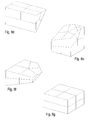
The remeshing schemes are illustrated in FIG. 8a-FIG. 8k. FIG. 8a shows the remeshing of the first part resulting from simple topology 1-7(a), and FIG. 8b shows the remeshing of the second part for this topology. FIG. 8c shows the remeshing of the first part resulting from simple topology 2-6(a), and FIG. 8d shows the remeshing of the second part for this topology. FIG. 8e shows the remeshing of the first part resulting from simple topology 3-5(a), and FIG. 8f shows the remeshing of the second part for this topology. FIG. 8g shows the remeshing for simple topology 4-4(a), and FIG. 8h shows the remeshing for simple topology 4-4(b). FIG. 8i shows the remeshing of the first part resulting from simple topology 4-4(c), and FIG. 8j shows the remeshing of the second part for this topology. FIG. 8k shows the remeshing for one part of simple topology 4-4(d).
The generation of the elements obeys to some extent the midpoint subdivision rules derived in the article by T. S. Li, R. M. McKeag and C. G. Armstrong, “Hexahedral meshing using midpoint subdivision and integer programming”, Comput. Methods Appl. Mech. Engng., 124, 171-193, 1995, although the position of the new nodes on the element faces and inside the element has been modified to get more stable elements within moderately deformed and twisted elements.
All newly generated elements in FIG. 8a-FIG. 8k are genuine 20-node brick elements. Furthermore, care is taken that the new meshes in adjacent elements with different topologies are compatible. For instance, there is a smooth transition between the new elements in FIG. 8b (topology 1-7(a)) and the new elements in FIG. 8c (topology 2-6(a)), and thus two adjacent elements with these topologies are consistently connected.
Most element faces bordering the triangulation in FIG. 8a-FIG. 8k are plane. The accommodation of curved surfaces (non-plane triangulations) is achieved through projection of the newly generated nodes onto the triangulation. However, before doing this, care is taken that edges and vertices in the triangulation are accurately modeled. To this end, each remeshing scheme has a node within the cutting shape, which is able to accurately model a vertex of the triangulation. For topology (1-7)a this is the node common to all three elements bordering the cutting shape in FIG. 8b. This node can be freely used to model a vertex of the structure by positioning it on the vertex location. This is illustrated in FIG. 9. Similarly, the other nodes in the cutting shape can be used to model edges of the triangulation. This can also be seen in FIG. 9.
It is clear that each simple topology can model only a limited number of vertices and edges. If very closely located vertices or edges occur, the master mesh has to be refined. Alternatively, an additional cutting can be performed after the reduction to simple topologies and before remeshing. This is shown in FIG. 10a and FIG. 10b where the triangulation has led to a 2-6(b) topology with two edges close together. A cutting plane was positioned in between these edges, leading to two simple topologies containing one edge each. Thereafter, remeshing was performed. This situation frequently occurs when modeling thin shell or plate structures.
When step 58 (FIG. 14) has been completed and all intersected elements have been processed (i.e., cut and remeshed), the elements not belonging to the structure are discarded. This is done in step 64. What remains is a mesh consisting of a thin layer of small elements at the surface of the structure, connected through multiple point constraints to the underlying coarser master elements.
The mesh resulting from step 64 can already be satisfactory to the user since most stresses of interest occur at the free surface. However, in some embodiments of the invention, the multiple point constraints are be pushed to deeper layers by remeshing additional inner layers of elements, if the user wishes to do so. This is possible since all uncut element faces of the simple topologies are remeshed in the same way, leading to four new faces as illustrated by the upper surface of FIG. 10b. Meshing additional adjacent element layers is achieved by subdividing these adjacent elements in eight new elements. By doing so, the MPCs are moved one layer deeper into the structure. This is paid for by additional elements leading to increased computational times. Ultimately, all MPCs can be removed by pursuing the technique until exhaustion leaving a MPC-less pure 20-node brick element mesh.
Smoothing procedures can further improve the mesh quality and are therefore performed in some embodiments of the invention. In the present exemplary embodiment, two different techniques are applied in step 66 (FIG. 14). In alternative embodiments, step 66 can be omitted or other or additional smoothing and/or modification steps can be performed.
The first smoothing procedure performed in step 66 consists of a robust optimization routine based on the Nelder-Mead method (see G. E. Gill, W. Murray and M. H. Wright, Practical optimization, Academic Press, London, 1981). Purpose of the optimization is to ensure that the Jacobian determinant is positive in all integration points of the newly created elements. A negative Jacobian determinant corresponds to a negative volume and surely leads to a crash of every finite element code. First, all elements in which a negative Jacobian occurs, if any, are determined. The end nodes belonging to each of these elements are subsequently allowed to move and the smallest Jacobian determinant in the integration points of the element and its neighbors is maximized. Furthermore, the middle nodes are kept within a reasonable distance from the geometric middle point of their adjacent end nodes. Experience has shown that this method is very effective, but it does not necessarily result in visually pleasing meshes.
The second smoothing procedure performed in step 66 consists of a weighted Laplace smoothing as described in the article by T. D. Blacker and M. B. Stephenson, “Paving: a new approach to automated quadrilateral mesh generation”, Int. J. Numer. Meth. Engng., 32, 811-847, 1991. In this procedure, each node is moved depending on the position of its neighbors. It usually results in a visually improved mesh. However, there is no guarantee that the Jacobian determinant in some elements might not deteriorate. Examples of this procedure can be found in a recent article on crack propagation calculations by the present inventor having the title “Cutting of a 3-D finite element mesh for automatic mode I crack propagation calculations”, Int. J. Numer. Meth. Engng., 42, 749-772, 1998.
The method of the present invention is completed with the a posteriori modifications. The generated three-dimensional mesh can now be used for subsequent three-dimensional structural finite element calculations. The techniques used for this calculations are well known per se and are not the subject of the present invention.
In the following, three examples are presented to illustrate the effectiveness of the method.
The first example is an aircraft engine disk segment (FIG. 11a) with U-notch and drive arm (FIG. 11b). The master mesh consisted of a regular rectangular grid. If the segment had included a larger angle, one could also consider to take an axisymmetric master mesh. The drive arm is very thin leading to doubly cut edges. Thus, additional cutting was performed before remeshing. This is shown in FIG. 11b: on the level of the drive arm there is an increase in mesh density. After remeshing a regular and smooth mesh results. No additional layer remeshing or smoothing was performed. Linear elastic stress calculations yielded values comparable to those obtained with a standard mesh generator.
The second example is a machine part with different levels of detail (FIG. 12): the external shape of the part and the big hole in the middle constitute a rather coarse level, whereas the several small holes represent a much finer level of detail. Meshing this part in one step would require a very fine master mesh to catch the small holes. Therefore, a two-step procedure is taken. First, the external geometry and the big hole are inserted, and a MPC-less mesh is generated. Due to the cutting procedure used this mesh has about eight times more elements than the original master mesh. Thus, by using this mesh as master mesh for the insertion of the small holes, a higher level of accuracy can be achieved. To limit the amount of elements, the remeshing in the second step was limited to the intersected elements, and appropriate MPCs were automatically generated.
Especially to be noticed in FIG. 12 are the accurate modeling of the intersection of one of the small holes with the large hole and the transition of the fine mesh to the coarse mesh around the sides of the small holes. At the boundary between both meshes the MPCs are applied. Again, the stress field is smooth (also across the MPCs) and corresponds to what is expected.
The third example (FIG. 13b) is the curved plate already shown in FIG. 1 and FIG. 3: its thickness to length ratio is 1:10. Principally, the present method is not ideal for such slender structures. Indeed, meshing the midsurface with shell elements and expanding them in the thickness direction leads to a much smoother mesh. However, also bulky structures can exhibit locally slender details and a general meshing program must be able to tackle such situations.
The master mesh was generated in an automatic way and quite a few complex topologies were detected, all of them covered by FIG. 5, i.e. no edges were cut more than once. The reduction of the complex geometries to simple ones was performed through cutting leading to a new master mesh shown in FIG. 13a. Several element layers were cut in different directions, leading to a local refinement of the master mesh. Then, the simple topologies were remeshed leading to the mesh in FIG. 13b. All MPCs were removed through continued remeshing.
The final mesh consisted of 5,136 elements and 24,117 nodes. The run time of the meshing procedure was about 45 seconds on an average workstation. No additional smoothing was performed, and all Jacobian determinants were positive. The mesh clearly shows the nature of the master mesh. Keeping the left face in FIG. 13b fixed in all directions, and pulling on the other end in the negative z-direction led to normal stresses exhibiting the expected bending distribution. This example shows that even without additional smoothing good results can be obtained for structures which do not have an ideal geometry for the automatic meshing procedure of the present invention.

Claims (11)

What is claimed is:
1. A method for generating a three-dimensional mesh for a structure, said method comprising the steps of:
providing a triangulation of the surface of said structure;
providing a three-dimensional master mesh which encompasses said structure, said master mesh having one or more component elements;
processing at least those component elements of the three-dimensional master mesh that are intersected by said triangulation such that component elements internal to said structure correspond to elements of said three-dimensional mesh each having a first predetermined topological property; and
discarding component elements of the master mesh external to said structure;
wherein the processing step includes performing at least one of the steps of cutting and remeshing at least those component elements of the master mesh that are intersected by said triangulation.
2. The method of claim 1, wherein said three-dimensional mesh is a hexahedral mesh.
3. The method of claim 2, wherein the hexahedral mesh includes 20-node elements.
4. The method of claim 2, wherein said first predetermined topological property is that each of said elements of said three-dimensional mesh is a hexahedral element.
5. The method of claim 4 wherein said hexahedral element is a 20-node brick element.
6. The method of claim 1, wherein the step of cutting comprises cutting component elements intersected by said triangulation according to a first set of predetermined rules in order to generate cut elements each having a second predetermined topological property,
and wherein the step of remeshing comprises remeshing said cut elements having said second predetermined topological property according to a second set of predetermined rules in order to generate elements of said three-dimensional mesh each having said first predetermined topological property.
7. The method of claim 6, wherein said second predetermined topological property comprises a first condition that each edge of each cut element is intersected only once by said triangulation, and a second condition that each cut element is divided into at most two parts by said intersection with said triangulation.
8. The method of claim 1, wherein the step of providing a three-dimensional master mesh which encompasses said structure comprises the sub-steps of:
generating a non-optimized master mesh, and
modifying said non-optimized master mesh such that each edge that are intersected by said triangulation close to its end nodes is moved.
9. The method of claim 8, wherein said non-optimized master mesh is a regular rectangular grid.
10. The method of claim 1, further comprising the step of performing at least one a posteriori modification to said elements of said three-dimensional mesh.
11. The method of claim 10, wherein said at least one a posteriori modification is a smoothing operation.
US09/640,365 1999-08-16 2000-08-16 Generating a three-dimensional mesh for finite element analysis Expired - Fee Related US6804635B1 (en)

Applications Claiming Priority (2)

Application Number Priority Date Filing Date Title
EP99115188A EP1077431A1 (en) 1999-08-16 1999-08-16 Generating a three-dimensional mesh for finite element analysis
EP99115188 1999-08-16

Publications (1)

Publication Number Publication Date
US6804635B1 true US6804635B1 (en) 2004-10-12

Family

ID=8238704

Family Applications (1)

Application Number Title Priority Date Filing Date
US09/640,365 Expired - Fee Related US6804635B1 (en) 1999-08-16 2000-08-16 Generating a three-dimensional mesh for finite element analysis

Country Status (3)

Country Link
US (1) US6804635B1 (en)
EP (1) EP1077431A1 (en)
JP (1) JP2001076029A (en)

Cited By (28)

* Cited by examiner, † Cited by third party
Publication number Priority date Publication date Assignee Title
US20020120430A1 (en) * 2001-02-23 2002-08-29 Korea Advanced Institute Of Science And Technology Hexahedral finite element modeling method for controlling element size and storage medium therefor
US20020183993A1 (en) * 2001-05-31 2002-12-05 Nec Corporation Analysis method using finite element method, program causing computer to execute same, and system for same
US20030088389A1 (en) * 2001-10-29 2003-05-08 Remis Balaniuk Long elements method for simulation of deformable objects
US20040039465A1 (en) * 2002-08-23 2004-02-26 Boyer Larry Paul Modular tooling approach to major structural repair
US20040148143A1 (en) * 2003-01-24 2004-07-29 The Boeing Company Method and interface elements for finite-element fracture analysis
US20070007382A1 (en) * 2005-04-08 2007-01-11 Charles-Andre De Hillerin Solver for a restrained deformable system with released degrees of freedom
US20070292016A1 (en) * 2006-06-14 2007-12-20 Tomonaga Okabe Element splitting method, element splitting arithmetic device and damage extension analysis device
US20080083213A1 (en) * 2006-09-22 2008-04-10 Mitsubishi Jidosha Kogyo Kabushiki Kaisha HC trap catalyst and preparation method for HC trap catalyst
US20080093163A1 (en) * 2004-10-26 2008-04-24 Silentor Holding A/S Silencer and Open-Structured Catalyser
US20080100619A1 (en) * 2006-10-25 2008-05-01 Coretech System Co., Ltd. Mesh generation method and computer-readable article for executing the method
US20080143717A1 (en) * 2006-12-15 2008-06-19 Concepts Eti, Inc. First-Point Distance Parameter System and Method for Automatic Grid Generation
US20080147758A1 (en) * 2006-12-15 2008-06-19 Concepts Eti, Inc. Variational Error Correction System and Method of Grid Generation
US20080147351A1 (en) * 2006-12-15 2008-06-19 Concepts Eti, Inc. Source Decay Parameter System and Method for Automatic Grid Generation
US20080147352A1 (en) * 2006-12-15 2008-06-19 Concepts Eti, Inc. Jacobian Scaling Parameter System and Method for Automatic Grid Generation
US20080183436A1 (en) * 2007-01-30 2008-07-31 Industrial Technology Research Institute Method of evolutionary optimization algorithm for structure design
US20090244061A1 (en) * 2004-12-17 2009-10-01 Koninklijke Philips Electronics, N.V. High quality accurate surface triangulation from a simplex mesh
US7671858B1 (en) * 2005-09-06 2010-03-02 Sandia Corporation Unconstrained paving and plastering method for generating finite element meshes
US20100086208A1 (en) * 2008-10-08 2010-04-08 Microsoft Corporation Almost rectangular triangulations
WO2012057735A1 (en) * 2010-10-25 2012-05-03 Nasser Saebi Method of performing a finite element analysis of a composite structure
WO2013106465A1 (en) * 2012-01-09 2013-07-18 Kla-Tencor Corporation Method and system for determining one or more optical characteristics of structure of a semiconductor wafer
US20150339409A1 (en) * 2014-05-20 2015-11-26 The Boeing Company Mid-surface extraction for finite element analysis
US9892219B2 (en) 2014-01-28 2018-02-13 Rolls-Royce Corporation Using fracture mechanism maps to predict time-dependent crack growth behavior under dwell conditions
US9922458B2 (en) 2013-11-04 2018-03-20 The University Of British Columbia Methods and systems for generating polycube segmentations from input meshes of objects
US9972128B2 (en) 2012-07-20 2018-05-15 The University Of British Columbia Methods and systems for generating polycubes and all-hexahedral meshes of an object
US10210657B2 (en) 2015-07-24 2019-02-19 The University Of British Columbia Methods and systems for hex-mesh optimization via edge-cone rectification
US10282495B2 (en) 2015-07-27 2019-05-07 Baker Hughes Incorporated Methods of evaluating performance of cutting elements for earth-boring tools
CN111222242A (en) * 2020-01-06 2020-06-02 广州中国科学院工业技术研究院 Method for geometric cutting and grid optimization based on grid and electronic equipment
US11090562B2 (en) * 2017-12-29 2021-08-17 Netease (Hangzhou) Network Co., Ltd. Method and apparatus for generating virtual resources in three-dimensional game scene

Families Citing this family (11)

* Cited by examiner, † Cited by third party
Publication number Priority date Publication date Assignee Title
KR100374797B1 (en) * 2000-03-14 2003-03-03 삼성전자주식회사 Method for processing nodes in 3D scene and the apparatus thereof
JP4679757B2 (en) * 2001-06-01 2011-04-27 パナソニック株式会社 3D graphic generation apparatus and 3D graphic generation method
KR100718119B1 (en) * 2001-07-09 2007-05-14 삼성전자주식회사 Method and apparatus for coding and decoding three dimension mesh information
KR100487753B1 (en) * 2002-10-29 2005-05-06 (주)사나이시스템 Method and system of mesh generation for numerical analysis of liquid crystal display by computer simulation
WO2004084100A1 (en) * 2003-03-17 2004-09-30 Caedom Inc. Element division apparatus, method thereof, program thereof, and recording medium containing the program
KR100512760B1 (en) * 2003-12-23 2005-09-07 한국전자통신연구원 Method for generating 3d mesh from 3d points by using shrink-wrapping scheme of boundary cells
KR101334173B1 (en) 2006-01-11 2013-11-28 삼성전자주식회사 Method and apparatus for encoding/decoding graphic data
GB2476417B (en) * 2006-01-11 2011-07-27 Samsung Electronics Co Ltd Method and apparatus for encoding/decoding graphic data
KR100863075B1 (en) 2007-03-30 2008-10-10 쎄딕(주) System and Method for automatic CAE analysis based on the web
CN101383047B (en) * 2007-09-03 2011-05-04 鸿富锦精密工业(深圳)有限公司 Curved surface meshing method
GB2515266B (en) * 2013-05-09 2018-02-28 Disney Entpr Inc Manufacturing Process for 3D Printed Objects

Citations (6)

* Cited by examiner, † Cited by third party
Publication number Priority date Publication date Assignee Title
US5113490A (en) 1989-06-19 1992-05-12 Silicon Graphics, Inc. Method for forming a computer model from an intersection of a cutting surface with a bounded volume
US5731817A (en) 1995-10-11 1998-03-24 Motorola, Inc. Method and apparatus for generating a hexahedron mesh of a modeled structure
US5774696A (en) * 1995-05-29 1998-06-30 Nec Corporation Triangle and tetrahedron mesh generation method
US5936869A (en) 1995-05-25 1999-08-10 Matsushita Electric Industrial Co., Ltd. Method and device for generating mesh for use in numerical analysis
US6392647B1 (en) * 1996-10-16 2002-05-21 Viewpoint Corporation System and method for computer modeling of 3D objects or surfaces by mesh constructions having optimal quality characteristics and dynamic resolution capabilities
US6445390B1 (en) * 1997-12-29 2002-09-03 The United States Of America As Represented By The Adminstrator Of The National Aeronautics And Space Administration Triangle geometry processing for surface modeling and cartesian grid generation

Patent Citations (6)

* Cited by examiner, † Cited by third party
Publication number Priority date Publication date Assignee Title
US5113490A (en) 1989-06-19 1992-05-12 Silicon Graphics, Inc. Method for forming a computer model from an intersection of a cutting surface with a bounded volume
US5936869A (en) 1995-05-25 1999-08-10 Matsushita Electric Industrial Co., Ltd. Method and device for generating mesh for use in numerical analysis
US5774696A (en) * 1995-05-29 1998-06-30 Nec Corporation Triangle and tetrahedron mesh generation method
US5731817A (en) 1995-10-11 1998-03-24 Motorola, Inc. Method and apparatus for generating a hexahedron mesh of a modeled structure
US6392647B1 (en) * 1996-10-16 2002-05-21 Viewpoint Corporation System and method for computer modeling of 3D objects or surfaces by mesh constructions having optimal quality characteristics and dynamic resolution capabilities
US6445390B1 (en) * 1997-12-29 2002-09-03 The United States Of America As Represented By The Adminstrator Of The National Aeronautics And Space Administration Triangle geometry processing for surface modeling and cartesian grid generation

Non-Patent Citations (6)

* Cited by examiner, † Cited by third party
Title
Blacker et al., Paving: a New Approach to Automated Quadrilateral Mesh Generation, Int. J. Numer. Meth. Engng., 32, 811-847, 1991.
G. Dhondt, Cutting of a 3-D Finite Element Mesh for Automatic Mode I Crack Propagation Calculations, Int. J. Numer Meth. Engng. 42, 749-772 (1998).
Li et al., Hexahedral Meshing Using Midpoint Subdivision and Integer Programming, Comput. Methods Appl. Mech. Engng., 124, 171-193, 1995).
R. Schneiders, A Grid-based Algorithm for the Generation of Hexahedral Element Meshes, Engineering with Computers, 12, 168-177, 1996).
S. Pissanetzky, Kubik: An Automatic Three-dimensional Finite Element Mesh Generator, Int. J. Numer. Meth. Engng., 17, 225-269, 1981).
Shephard, et al., Automatic Three-dimensional Mesh Generation by the Finite Octree Technique, Int. J. Numer. Meth. Engng., 32, 709-749, 1991).

Cited By (45)

* Cited by examiner, † Cited by third party
Publication number Priority date Publication date Assignee Title
US20020120430A1 (en) * 2001-02-23 2002-08-29 Korea Advanced Institute Of Science And Technology Hexahedral finite element modeling method for controlling element size and storage medium therefor
US6999908B2 (en) * 2001-02-23 2006-02-14 Korea Advanced Institute Of Science And Technology Hexahedral finite element modeling method for controlling element size and storage medium therefor
US20020183993A1 (en) * 2001-05-31 2002-12-05 Nec Corporation Analysis method using finite element method, program causing computer to execute same, and system for same
US20090312991A1 (en) * 2001-05-31 2009-12-17 Nec Corporation Analysis method using finite element method, program causing computer to execute same, and system for same
US8229712B2 (en) 2001-05-31 2012-07-24 Nec Corporation Analysis method using finite element method, program causing computer to execute same, and system for same
US7363198B2 (en) * 2001-10-29 2008-04-22 The Board Of Trustees Of The Leland Stanford Junior University Long elements method for simulation of deformable objects
US20030088389A1 (en) * 2001-10-29 2003-05-08 Remis Balaniuk Long elements method for simulation of deformable objects
US20040039465A1 (en) * 2002-08-23 2004-02-26 Boyer Larry Paul Modular tooling approach to major structural repair
US20040148143A1 (en) * 2003-01-24 2004-07-29 The Boeing Company Method and interface elements for finite-element fracture analysis
US7505885B2 (en) * 2003-01-24 2009-03-17 The Boeing Company Method and interface elements for finite-element fracture analysis
US20080093163A1 (en) * 2004-10-26 2008-04-24 Silentor Holding A/S Silencer and Open-Structured Catalyser
US20090244061A1 (en) * 2004-12-17 2009-10-01 Koninklijke Philips Electronics, N.V. High quality accurate surface triangulation from a simplex mesh
US8222581B2 (en) * 2005-04-08 2012-07-17 Dassault Systemes Solver for a restrained deformable system with released degrees of freedom
US20070007382A1 (en) * 2005-04-08 2007-01-11 Charles-Andre De Hillerin Solver for a restrained deformable system with released degrees of freedom
US7671858B1 (en) * 2005-09-06 2010-03-02 Sandia Corporation Unconstrained paving and plastering method for generating finite element meshes
US20070292016A1 (en) * 2006-06-14 2007-12-20 Tomonaga Okabe Element splitting method, element splitting arithmetic device and damage extension analysis device
US7991215B2 (en) * 2006-06-14 2011-08-02 Fuji Jukogyo Kabushiki Kaisha Element splitting method, element splitting arithmetic device and damage extension analysis device
US20080083213A1 (en) * 2006-09-22 2008-04-10 Mitsubishi Jidosha Kogyo Kabushiki Kaisha HC trap catalyst and preparation method for HC trap catalyst
US20080100619A1 (en) * 2006-10-25 2008-05-01 Coretech System Co., Ltd. Mesh generation method and computer-readable article for executing the method
US7577547B2 (en) 2006-12-15 2009-08-18 Concepts Eti, Inc. Jacobian scaling parameter system and method for automatic grid generation
US20080147758A1 (en) * 2006-12-15 2008-06-19 Concepts Eti, Inc. Variational Error Correction System and Method of Grid Generation
US7577546B2 (en) 2006-12-15 2009-08-18 Concepts Eti, Inc. Source decay parameter system and method for automatic grid generation
WO2008076990A1 (en) * 2006-12-15 2008-06-26 Concepts Eti, Inc. First-point distance parameter system and method for automatic grid generation
WO2008076993A2 (en) * 2006-12-15 2008-06-26 Concepts Eti, Inc. Variational error correction system and method of grid generation
US20080147352A1 (en) * 2006-12-15 2008-06-19 Concepts Eti, Inc. Jacobian Scaling Parameter System and Method for Automatic Grid Generation
WO2008076993A3 (en) * 2006-12-15 2008-08-14 Concepts Eti Inc Variational error correction system and method of grid generation
US20080147351A1 (en) * 2006-12-15 2008-06-19 Concepts Eti, Inc. Source Decay Parameter System and Method for Automatic Grid Generation
US8112245B2 (en) 2006-12-15 2012-02-07 Concepts Eti, Inc. First-point distance parameter system and method for automatic grid generation
US20080143717A1 (en) * 2006-12-15 2008-06-19 Concepts Eti, Inc. First-Point Distance Parameter System and Method for Automatic Grid Generation
US20080183436A1 (en) * 2007-01-30 2008-07-31 Industrial Technology Research Institute Method of evolutionary optimization algorithm for structure design
US8269762B2 (en) 2008-10-08 2012-09-18 Microsoft Corporation Almost rectangular triangulations
US20100086208A1 (en) * 2008-10-08 2010-04-08 Microsoft Corporation Almost rectangular triangulations
WO2012057735A1 (en) * 2010-10-25 2012-05-03 Nasser Saebi Method of performing a finite element analysis of a composite structure
WO2013106465A1 (en) * 2012-01-09 2013-07-18 Kla-Tencor Corporation Method and system for determining one or more optical characteristics of structure of a semiconductor wafer
US8675188B2 (en) 2012-01-09 2014-03-18 Kla-Tencor Corporation Method and system for determining one or more optical characteristics of structure of a semiconductor wafer
US9448184B1 (en) 2012-01-09 2016-09-20 Kla-Tencor Corporation Method and system for determining one or more optical characteristics of structure of a semiconductor wafer
US9972128B2 (en) 2012-07-20 2018-05-15 The University Of British Columbia Methods and systems for generating polycubes and all-hexahedral meshes of an object
US9922458B2 (en) 2013-11-04 2018-03-20 The University Of British Columbia Methods and systems for generating polycube segmentations from input meshes of objects
US9892219B2 (en) 2014-01-28 2018-02-13 Rolls-Royce Corporation Using fracture mechanism maps to predict time-dependent crack growth behavior under dwell conditions
US20150339409A1 (en) * 2014-05-20 2015-11-26 The Boeing Company Mid-surface extraction for finite element analysis
US10042962B2 (en) * 2014-05-20 2018-08-07 The Boeing Company Mid-surface extraction for finite element analysis
US10210657B2 (en) 2015-07-24 2019-02-19 The University Of British Columbia Methods and systems for hex-mesh optimization via edge-cone rectification
US10282495B2 (en) 2015-07-27 2019-05-07 Baker Hughes Incorporated Methods of evaluating performance of cutting elements for earth-boring tools
US11090562B2 (en) * 2017-12-29 2021-08-17 Netease (Hangzhou) Network Co., Ltd. Method and apparatus for generating virtual resources in three-dimensional game scene
CN111222242A (en) * 2020-01-06 2020-06-02 广州中国科学院工业技术研究院 Method for geometric cutting and grid optimization based on grid and electronic equipment

Also Published As

Publication number Publication date
JP2001076029A (en) 2001-03-23
EP1077431A1 (en) 2001-02-21

Similar Documents

Publication Publication Date Title
US6804635B1 (en) Generating a three-dimensional mesh for finite element analysis
EP1710720B1 (en) Method of computer-aided design of a modeled object having several faces
CN106133628B (en) The method and system in the path of the cutter for determining processing groove shapes
CN113366481A (en) Boundary-based generative design under 2.5-axis subtractive manufacturing constraints for computer-aided design and manufacturing
US7477262B2 (en) Automatic calculation of minimum and maximum tolerance stack
US11243510B2 (en) Computer aided generative design with tool size control to facilitate 2.5-axis subtractive manufacturing processes
Mobley et al. An Object Oriented Approach to Geometry Defeaturing for Finite Element Meshing.
EP1645979A1 (en) Method and program for generating volume data from boundary representation data
CN106504331A (en) Tooth modeling method based on three-dimensional model search
US20220373996A1 (en) Computer aided generative design with filtering to facilitate 2.5-axis subtractive manufacturing processes
US11762368B2 (en) Computer aided generative design with layer boundary determination to facilitate 2.5-axis subtractive manufacturing processes
Mahdavi-Amiri et al. VDAC: volume decompose-and-carve for subtractive manufacturing
Dhondt A new automatic hexahedral mesher based on cutting
Fu et al. A graph grammar based approach to automated manufacturing planning
Xiaodong et al. Mesh simplification based on super-face and genetic algorithm in reverse engineering
JP2023528760A (en) 2. Computer Aided Generative Design with Filtering to Facilitate the 5-Axis Subtractive Manufacturing Process
Dhondt Unstructured 20-node brick element meshing
Xú et al. Feature recognition for virtual machining
Karamete et al. Recovery of an arbitrary edge on an existing surface mesh using local mesh modifications
JP2023084699A (en) Computer aided generative design with feature thickness control to facilitate manufacturing and structural performance
Borodin et al. Out-of-Core Simplification with Guaranteed Error Tolerance.
Pan et al. A validity-and kinematics-aware approach for optimizing fabrication orientation
JP4675042B2 (en) Method for generating a three-dimensional object
Han et al. Space cutter radius compensation based on shape reconstruction for multi-axis milling
CN103207929A (en) Three-dimensional shape generation method, program and recording medium

Legal Events

Date Code Title Description
AS Assignment

Owner name: MTU MOTOREN-UND TURBINEN-UNION MUNCHEN GMBH, GERMA

Free format text: ASSIGNMENT OF ASSIGNORS INTEREST;ASSIGNOR:DHONDT, GUIDO;REEL/FRAME:011252/0429

Effective date: 20000915

FEPP Fee payment procedure

Free format text: PAYOR NUMBER ASSIGNED (ORIGINAL EVENT CODE: ASPN); ENTITY STATUS OF PATENT OWNER: LARGE ENTITY

AS Assignment

Owner name: MTU AERO ENGINES GMBH, GERMANY

Free format text: CHANGE OF NAME;ASSIGNOR:MTU MOTOREN-UND TURBINEN-UNION MUNCHEN GMBH;REEL/FRAME:015597/0032

Effective date: 20000918

CC Certificate of correction
FPAY Fee payment

Year of fee payment: 4

FPAY Fee payment

Year of fee payment: 8

REMI Maintenance fee reminder mailed
LAPS Lapse for failure to pay maintenance fees
STCH Information on status: patent discontinuation

Free format text: PATENT EXPIRED DUE TO NONPAYMENT OF MAINTENANCE FEES UNDER 37 CFR 1.362

FP Lapsed due to failure to pay maintenance fee

Effective date: 20161012