US6813411B2 - Optical switch - Google Patents
Optical switch Download PDFInfo
- Publication number
- US6813411B2 US6813411B2 US10/086,617 US8661702A US6813411B2 US 6813411 B2 US6813411 B2 US 6813411B2 US 8661702 A US8661702 A US 8661702A US 6813411 B2 US6813411 B2 US 6813411B2
- Authority
- US
- United States
- Prior art keywords
- output
- input
- fibers
- fiber
- optical
- Prior art date
- Legal status (The legal status is an assumption and is not a legal conclusion. Google has not performed a legal analysis and makes no representation as to the accuracy of the status listed.)
- Expired - Fee Related, expires
Links
Images


Classifications
-
- G—PHYSICS
- G02—OPTICS
- G02B—OPTICAL ELEMENTS, SYSTEMS OR APPARATUS
- G02B6/00—Light guides; Structural details of arrangements comprising light guides and other optical elements, e.g. couplings
- G02B6/24—Coupling light guides
- G02B6/26—Optical coupling means
- G02B6/35—Optical coupling means having switching means
- G02B6/351—Optical coupling means having switching means involving stationary waveguides with moving interposed optical elements
- G02B6/3512—Optical coupling means having switching means involving stationary waveguides with moving interposed optical elements the optical element being reflective, e.g. mirror
- G02B6/352—Optical coupling means having switching means involving stationary waveguides with moving interposed optical elements the optical element being reflective, e.g. mirror the reflective optical element having a shaped reflective surface, e.g. a reflective element comprising several reflective surfaces or facets that function together
-
- G—PHYSICS
- G02—OPTICS
- G02B—OPTICAL ELEMENTS, SYSTEMS OR APPARATUS
- G02B6/00—Light guides; Structural details of arrangements comprising light guides and other optical elements, e.g. couplings
- G02B6/24—Coupling light guides
- G02B6/26—Optical coupling means
- G02B6/35—Optical coupling means having switching means
- G02B6/351—Optical coupling means having switching means involving stationary waveguides with moving interposed optical elements
- G02B6/3512—Optical coupling means having switching means involving stationary waveguides with moving interposed optical elements the optical element being reflective, e.g. mirror
- G02B6/3514—Optical coupling means having switching means involving stationary waveguides with moving interposed optical elements the optical element being reflective, e.g. mirror the reflective optical element moving along a line so as to translate into and out of the beam path, i.e. across the beam path
-
- G—PHYSICS
- G02—OPTICS
- G02B—OPTICAL ELEMENTS, SYSTEMS OR APPARATUS
- G02B6/00—Light guides; Structural details of arrangements comprising light guides and other optical elements, e.g. couplings
- G02B6/24—Coupling light guides
- G02B6/26—Optical coupling means
- G02B6/35—Optical coupling means having switching means
- G02B6/354—Switching arrangements, i.e. number of input/output ports and interconnection types
- G02B6/3544—2D constellations, i.e. with switching elements and switched beams located in a plane
- G02B6/3546—NxM switch, i.e. a regular array of switches elements of matrix type constellation
Definitions
- the present invention relates to an optical switch for use in fiber communication and optical network technology, and particularly to a mechanically operated optical switch with a plurality of reflectors as a switching element.
- Optical signals are commonly transmitted in optical fibers, which provide efficient light channels through which optical signals can pass.
- optical fibers have been used in various fields, including telecommunications, where light passing through an optical fiber is used to convey either digital or analog information. Efficient switching of optical signals between individual fibers is necessary in most optical processing systems or networks to achieve the desired routing of the signals.
- optical switches come in two different designs: in one design, the optical components move, and in the other design, the fibers move. Factors for assessing the capability of an optical switch include low insertion loss ( ⁇ 1 dB), good isolation performance (>50 dB) and bandwidth capacity compatible with the fiber network the switch is supporting.
- Moving fiber switches involves the actual physical movement of one or more of the fibers to specific positions to accomplish the transmission of a light beam from one fiber end to another under selected switching conditions.
- Moving optical component switches includes optical collimating lenses which expand the light beam coming from the fibers, and then, by using moving prisms or mirrors, redirecting the expanded light beam to other fibers as required by the switching process.
- Moving fiber switches involve the actual physical movement of one or more of the fibers to specific positions to accomplish the transmission of a light beam from one fiber end to another under selected switching conditions.
- Moving optical component switches include optical collimating lenses which expand the light beam coming from the fibers, and then by using moving prisms or mirrors, redirect the expanded light beam to other fibers as required by the switching process.
- the moving fiber switches have a stringent tolerance requirement for the amount and direction of fiber movement.
- the tolerance is typically a small fraction of the fiber core diameter for two fibers to precisely collimate to reduce loss.
- the fibers themselves are quite thin and may be subject to breakage if not properly protected.
- reinforcing the fibers with stiff protective sheaths makes the fibers less flexible, increasing the force required to manipulate each fiber into alignment.
- these moving fiber switches share a common problem of requiring high precision parts to obtain precise position control and low insertion loss. This results in high cost and complicated manufacture of the switches.
- frequently moving fibers to and fro is apt to damage or even break the fibers.
- the moving optical component switches in contrast, have less stringent movement control tolerance requirements.
- the presence of the collimating lenses allows relaxation of the tolerance requirements.
- U.S. Pat. No. 5,742,712 describes a mechanical optical switch, which relies on a mirror 420 being moveable into an optical path between a first and second fixed collimating lenses ( 428 , 436 ).
- the moveable mirror 420 is displaced out of the optical path (FIG. 9 )
- the light signals from a first input fiber 422 are transmitted to a second output fiber 432 and the light signals from a second input fiber 430 are transmitted to a first output fiber 424 through the first and second collimating lenses ( 428 , 436 ).
- the moveable mirror 420 is moved into the optical path (FIG.
- the light signals from the first input fiber 422 are reflected back through the first collimating lens 428 into the first output fiber 424 , which is parallel to and in close proximity with the first input fiber 422 .
- the light signals from the second input fiber 430 are likewise reflected back through the second collimating lens 436 into the second output fiber 432 , which is parallel to and in close proximity with the second input fiber 430 .
- the gap between the two collimating lenses ( 428 , 436 ), must be sufficiently large to allow movement of the movable mirror 420 between the two collimating lenses.
- this gap has a significant effect on insertion losses across the switch. For this reason, the gap is preferably less than about 2.0 mm.
- the insertion of a two-surface mirror will introduce an insertion loss in an input/output port proportional to a thickness of the two-surface mirror.
- an improved optical switch is desired.
- an optical switch is desired which has high optical efficiency and which does not require precise alignment or movement of the optical fibers themselves.
- An object of the present invention is to provide an optical switch in which optical fibers don't move.
- Another object of the present invention is to provide an optical switch which allows easy alignment of associated fibers and which has a low insertion loss.
- Yet another object of the present invention is to provide an optical switch which uses a plurality of reflectors as a switching element.
- An optical switch comprises a base, a switching element, a first input port, a first output port, a second input port, a second output port, a third input port, a third output port.
- Six symmetrical holders on the base hold the first input port, the second input port and the third input port in alignment with the first output port, the second output port and the third output port, respectively, allowing the light beams from one input port to be output by one of three different output ports.
- the switching element is accommodated in a space surrounded by the input and output ports.
- a driver connects to the switching element and drives the switching element to move in and out of the space and to rotate in the space to redirect the light beams transmitting from the input fibers to different the output fibers.
- FIG. 1 is a perspective view of an optical switch according to the present invention
- FIG. 2 is an optical elements cross-sectional view of the optical switch of FIG. 1 in a first position
- FIG. 3 is an optical elements cross-sectional view of the optical switch of FIG. 1 in a second position
- FIG. 4 is an optical elements cross-sectional view of the optical switch of FIG. 1 in a third position
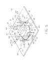
- FIG. 5 is a perspective view of a second embodiment of an optical switch according to the present invention.
- FIG. 6 is an optical elements cross-sectional view of the second embodiment optical switch of FIG. 5 in a first position
- FIG. 7 is an optical elements cross-sectional view of the second embodiment optical switch of FIG. 5 in a second position
- FIG. 8 is an optical elements cross-sectional view of the second embodiment optical switch of FIG. 5 in a third position
- FIG. 9 is an optical elements cross-sectional view of a prior art mechanical optical switch in a first position
- FIG. 10 is an optical elements cross-sectional view of the prior art switch of FIG. 9 in a second position.
- an optical switch 99 comprises a base 60 , a switching element 40 , a first input port 10 , a first output port 15 , a second input port 20 , a second output port 25 , a third input port 30 , and a third output port 35 .
- the base 60 has a space 67 in a center (not labeled) thereof, and six symmetrical holders 61 , 62 , 63 , 64 , 65 , 66 surrounding a circumference of the space 67 and extending upwardly from the base 60 .
- the holders 61 , 62 , 63 , 64 , 65 , 66 are angularly equally spaced, and each holds an input port or an output port. Specifically, they are spaced 60 degrees apart.
- the space 67 accommodates the switching element 40 .
- the switching element 40 comprises a supporter 45 , a three-surface mirror 41 mounted on a center of the supporter 45 , and a first reflector 42 , a second reflector 43 and a third reflector 44 mounted on a circumference of the supporter 45 .
- the three-surface mirror 41 is an equilateral triangle column, which defines a first reflecting surface 412 , a second reflecting surface 413 and a third reflecting surface 414 .
- the three reflecting surfaces 412 , 413 , 414 are positioned opposite to three reflecting surfaces of the three reflectors 42 , 43 , 44 , respectively, to cause light beam to reflect between the two opposing reflecting surfaces of the three-surface mirror 41 and the three reflectors 42 , 43 , 44 .
- the first input port 10 comprises a first input collimator 12 .
- a first input fiber 11 is inserted into the first input collimator 12 .
- the first output port 15 comprises a first output collimator 14 .
- a first output fiber 13 is inserted into the first output collimator 14 .
- the first input collimator 12 is opposite to and aligned with the first output collimator 14 to direct light beams from the first input fiber 11 to the first output fiber 13 .
- Each of the second input and output ports 20 , 25 and the third input and output ports 30 , 35 has a collimator 22 , 24 , 32 , 34 which accepts insertion of a fiber 21 , 23 , 31 , 33 in the exact same way as the first input and output ports 10 , 15 .
- the second input collimator 22 is opposite to and aligned with the second output collimator 24 to direct light beams from the second input fiber 22 to the second output fiber 23 .
- the third input collimator 32 is opposite to and aligned with third output collimator 34 to direct light beams from a third input fiber 31 to a third output fiber 33 .
- the sin collimators 12 , 14 , 22 , 24 , 32 , 34 are assembled in respective holders 63 , 66 , 61 , 64 , 65 , 62 and accept insertion of respective fibers 11 , 13 , 21 , 23 , 31 , 33 .
- the six symmetrical holders 61 , 62 , 63 , 64 , 65 , 66 of the base 60 hold the first input collimator 12 , the first output collimator 14 , the second input collimator 22 , the second output collimator 24 , the third input collimator 32 and the third output collimator 34 in alignment to allow light beams from each input fiber 11 , 21 , 31 to be output by the corresponding output fiber 13 , 23 , 33 when no element blocks the space 67 .
- the switching element 40 can be accommodated in the apace 67 surrounded by the input and output ports 10 , 15 , 20 , 25 , 30 , 35 .
- a driver (not shown) connects with the switching element 40 and drives the switching element to move in or out of the space 67 , or to rotate in the space 67 .
- the driver drives the switching element 40 to move between a first position, where the switching element 40 is positioned out of the space 67 , a second position, where the switching element 40 is positioned in the space 67 , and a third position, where the switching element 40 is positioned in the space 67 but is rotated anticlockwise 60 degrees relative to the second position.
- FIGS. 2-4 illustrate the operation of the optical switch 99 .
- the switching element 40 In the first position (FIG. 2 ), the switching element 40 is out of the space 67 .
- Light beams from the first, second and third input fibers 11 , 21 , 31 are directed to the first, second and third output fibers 13 , 23 , 33 through the first input and output collimators 12 , 14 , the second input and output collimators 22 , 24 and the third input and output collimators 32 , 34 , respectively.
- the switching element 40 is in the space 67 , and the first reflecting surface 412 is in the optical path of the first input collimator 12 and the third output collimator 34 , the second reflecting surface 413 is in the optical path of the second input collimator 22 and the first output collimator 14 , and the third reflecting surface 414 is in the optical path of the third input collimator 32 and the second output collimator 24 .
- Light beams from the first input fiber 11 transmit to the first reflecting surface 412 of the three-surface mirror 41 through the first input collimator 12 , and then reflect between the first reflecting surface 412 and the first reflector 42 to the third output collimator 34 and are output by the third output fiber 33 .
- light beams from the second input fiber 21 are reflected by the second reflecting surface 413 and the second reflector 43 and are output by the first output fiber 13
- light beams from the third input fiber 31 are reflected by the third reflecting surface 414 and the third reflector 44 and are output by the second output fiber 23 .
- the switching element 40 is rotated anticlockwise 60 degrees relative to the second position, so that the first reflecting surface 412 of the three-surface mirror 41 is in the optical path of the first input collimator 12 and the second output collimator 24 , the second reflecting surface 413 is in the optical path of the second input collimator 22 and the third output collimator 34 , and the third reflecting surface 414 is in the optical path of the third input collimator 32 and the first output collimator 14 .
- Light beams from the first input fiber 11 are directed to the first reflecting surface 412 by the first input collimator 12 , and then reflect between the first reflecting surface 412 and the first reflector 42 to the second output fiber 23 through the second output collimator 24 .
- light beams from the second input fiber 21 reflect between the second reflecting surface 413 and the second reflector 43 to the third output fiber 33 through the second input collimator 22 and the third output collimator 34
- light beams from the third input fiber 31 are reflected between the third reflecting surface 414 and the third reflector 44 to the first output fiber 13 through the third input collimator 32 and the first output collimator 14 .
- FIGS. 5-8 show drawings describing operation of a second embodiment of an optical switch in accordance with the present inventions, which is designed by the reference 99 ′ for distinction.
- the optical switch 99 ′ makes use of four reflectors to switch three input light beams among alternate optical paths.
- the four reflectors are a first reflector 42 ′, a second reflector 43 ′, a fourth reflector 47 and a fifth reflector 48 .
- the four reflectors 42 ′, 43 ′, 47 , 48 are mounted parallel to one another on the supporter 45 ′.
- the switching element 40 ′ connects with a driver (not shown), which drives the switching clement 40 ′ to rotate among three positions.
- the switching element 40 ′ is in a first position.
- the fourth reflector 47 is in the optical path of the second input collimator 22 ′ and the third output collimator 34 ′, and the fifth reflector 48 in the optical path of the third input collimator 32 ′ and the second output collimator 24 ′.
- Light beams from the first input fiber 11 ′ are directed to the first output fiber 13 ′ sequentially through the first input collimator 12 ′ and the first output collimator 14 ′.
- Light beams from the second input fiber 21 ′ are directed to the fourth reflector 47 through the second input collimator 22 ′, and are then reflected between the fourth reflector 47 and the second reflector 43 ′ to the third output fiber 33 ′ through the third output collimator 34 ′.
- light beams from the third input fiber 31 ′ pass through the third input collimator 32 ′, are reflected between the fifth reflector 48 and the first reflector 42 ′, and pass through the second output collimator 24 ′ to be output by the second output fiber 23 ′.
- the switching element 40 ′ is in a first position.
- the fourth reflector 47 is in the optical path of the second input collimator 22 ′ and the third output collimator 34 ′
- the fifth reflector 48 is in the optical path of the third input collimator 32 ′ and the second output collimator 24 ′.
- Light beams from the first input fiber 11 ′ are directed to the first output fiber 13 ′ sequentially through the first input collimator 12 ′ and the first output collimator 14 ′.
- Light beams from the second input fiber 21 ′ are directed to the fourth reflector 47 through the second input collimator 22 ′, and are then reflected between the fourth reflector 47 and the second reflector 43 ′ to the third output fiber 33 ′ through the third output collimator 34 ′.
- light beams from the third input fiber 31 ′ pass through the third input collimator 32 ′ are reflected between the fifth reflector 48 and the first reflector 42 ′, and pass through the second output collimator 24 ′ to be output by the second output fiber 23 ′.
- a second position of the switching element 40 ′ is rotated anticlockwise 60 degrees from the first position.
- the fourth reflector 47 is in the optical path of the first input collimator 12 ′ and the third output collimator 34 ′
- the fifth reflector is in the optical path of the third input collimator 32 ′ and the first output collimator 14 ′.
- Light beams from the second input fiber 21 ′ are directed to the second output fiber 23 ′ through the second input and output collimators 22 ′, 24 ′.
- Light beams from the first input fiber 11 ′ are directed to the fourth reflector 47 through the first collimator 12 ′, and then reflected between the fourth reflector 47 and the second reflector 43 ′ to the third output fiber 33 ′ through the third output collimator 34 ′.
- light beams from the third input fiber 31 ′ pass through the third input collimator 32 ′ and are reflected between the fifth reflector 48 and the first reflector 42 ′ to the first output fiber 13 ′.
- a third position of the switching element 40 ′ is rotated anticlockwise 120 degrees from the first position.
- the fourth reflector 47 is in the optical path of the first input collimator 12 ′ and the second output collimator 24 ′
- the fifth reflector 48 is in the optical path of the second input collimator 22 ′ and the first output collimator 14 ′.
- Light beams from the third input fiber 31 ′ are directed to the third output fiber 33 ′ through the third input and third output collimators 32 ′, 34 ′.
- Light beams from the first input fiber 11 ′ are directed to the fourth reflector 47 through the first collimator 12 ′, and are reflected between the fourth reflector 47 and the second reflector 43 ′ to the second output fiber 23 ′ through the second output collimator 24 ′.
- light beams from the second input fiber 21 ′ pass through the second input collimator 22 ′ are reflected between the fifth reflector 48 and the first reflector 42 ′ to the first output fiber 13 ′ via the first output collimator 14 ′.
- optical switch 99 of the present invention over those of the prior art include the following. First, only optical components of the optical switch move; no fibers move. Second, the input and output ports are easily aligned with one another. Third, the optical switch is of a relatively simple design and can be cheaply constructed.
- the optical switch may use the switching element 40 and the switching element 40 ′ in the same switch to realize different optical path switching possibilities.
Landscapes
- Physics & Mathematics (AREA)
- General Physics & Mathematics (AREA)
- Optics & Photonics (AREA)
- Mechanical Light Control Or Optical Switches (AREA)
Abstract
Description
Claims (13)
Applications Claiming Priority (3)
| Application Number | Priority Date | Filing Date | Title |
|---|---|---|---|
| TW90218619U | 2001-10-31 | ||
| TW90218619 | 2001-10-31 | ||
| TW090218619U TW505245U (en) | 2001-10-31 | 2001-10-31 | Optical switch having multiple optical paths |
Publications (2)
| Publication Number | Publication Date |
|---|---|
| US20030081886A1 US20030081886A1 (en) | 2003-05-01 |
| US6813411B2 true US6813411B2 (en) | 2004-11-02 |
Family
ID=21687140
Family Applications (1)
| Application Number | Title | Priority Date | Filing Date |
|---|---|---|---|
| US10/086,617 Expired - Fee Related US6813411B2 (en) | 2001-10-31 | 2002-02-28 | Optical switch |
Country Status (2)
| Country | Link |
|---|---|
| US (1) | US6813411B2 (en) |
| TW (1) | TW505245U (en) |
Families Citing this family (4)
| Publication number | Priority date | Publication date | Assignee | Title |
|---|---|---|---|---|
| US7940673B2 (en) | 2007-06-06 | 2011-05-10 | Veedims, Llc | System for integrating a plurality of modules using a power/data backbone network |
| US7856158B2 (en) * | 2008-03-07 | 2010-12-21 | Ballard Claudio R | Virtual electronic switch system |
| JP6306659B1 (en) * | 2016-10-19 | 2018-04-04 | ファナック株式会社 | Beam distributor |
| JP6339644B2 (en) * | 2016-10-19 | 2018-06-06 | ファナック株式会社 | Beam distributor |
Citations (7)
| Publication number | Priority date | Publication date | Assignee | Title |
|---|---|---|---|---|
| US5436986A (en) * | 1993-03-09 | 1995-07-25 | Tsai; Jian-Hung | Apparatus for switching optical signals among optical fibers and method |
| US5642446A (en) * | 1993-03-09 | 1997-06-24 | Tsai; Jian-Hung | Apparatus for switching optical signals among optical fibers |
| US6404943B1 (en) * | 1999-10-08 | 2002-06-11 | Agilent Technologies, Inc. | Apparatus and method for directing optical signals using a movable optical switching element |
| US20020146199A1 (en) * | 2001-04-09 | 2002-10-10 | Adc Telecommunications, Inc. | Mems optical balanced path switch |
| US20030081884A1 (en) * | 2001-10-31 | 2003-05-01 | Chih-Yuan Liao | Optic switch |
| US20030113057A1 (en) * | 2001-12-14 | 2003-06-19 | Chien-Cheng Chen | Optical switch |
| US6587614B2 (en) * | 2001-11-02 | 2003-07-01 | Hon Hai Precision Ind. Co., Ltd. | Optical switch |
-
2001
- 2001-10-31 TW TW090218619U patent/TW505245U/en not_active IP Right Cessation
-
2002
- 2002-02-28 US US10/086,617 patent/US6813411B2/en not_active Expired - Fee Related
Patent Citations (7)
| Publication number | Priority date | Publication date | Assignee | Title |
|---|---|---|---|---|
| US5436986A (en) * | 1993-03-09 | 1995-07-25 | Tsai; Jian-Hung | Apparatus for switching optical signals among optical fibers and method |
| US5642446A (en) * | 1993-03-09 | 1997-06-24 | Tsai; Jian-Hung | Apparatus for switching optical signals among optical fibers |
| US6404943B1 (en) * | 1999-10-08 | 2002-06-11 | Agilent Technologies, Inc. | Apparatus and method for directing optical signals using a movable optical switching element |
| US20020146199A1 (en) * | 2001-04-09 | 2002-10-10 | Adc Telecommunications, Inc. | Mems optical balanced path switch |
| US20030081884A1 (en) * | 2001-10-31 | 2003-05-01 | Chih-Yuan Liao | Optic switch |
| US6587614B2 (en) * | 2001-11-02 | 2003-07-01 | Hon Hai Precision Ind. Co., Ltd. | Optical switch |
| US20030113057A1 (en) * | 2001-12-14 | 2003-06-19 | Chien-Cheng Chen | Optical switch |
Also Published As
| Publication number | Publication date |
|---|---|
| TW505245U (en) | 2002-10-01 |
| US20030081886A1 (en) | 2003-05-01 |
Similar Documents
| Publication | Publication Date | Title |
|---|---|---|
| US5742712A (en) | Efficient electromechanical optical switches | |
| US5444801A (en) | Apparatus for switching optical signals and method of operation | |
| US5999669A (en) | High-reliability MXN fiber optic switches | |
| US5875271A (en) | Apparatus for switching optical signals and method of operation | |
| US6415067B1 (en) | N x M optical switch | |
| US4329017A (en) | Fiber optics communications modules | |
| US4626066A (en) | Optical coupling device utilizing a mirror and cantilevered arm | |
| US5757994A (en) | Three-part optical coupler | |
| US6259835B1 (en) | Mechanically actuated optical switch | |
| US6477289B1 (en) | Optical wedge switch | |
| US6647173B2 (en) | Optical switch with a moveable optical component | |
| CA2326362A1 (en) | Optical switch | |
| US20030012509A1 (en) | Switch and variable optical attenuator for single or arrayed optical channels | |
| US6813411B2 (en) | Optical switch | |
| EP1126304A2 (en) | Optical switch | |
| US6665462B2 (en) | Optical switch | |
| US6587614B2 (en) | Optical switch | |
| US20030202737A1 (en) | Optical switch | |
| US6704477B2 (en) | Optical switch | |
| US20030185497A1 (en) | Optical switch | |
| US7162118B1 (en) | Dual optical switch | |
| US6591031B2 (en) | Optical switch with movable mirror | |
| US6625344B2 (en) | Optical switch | |
| US6697549B2 (en) | Optical switch | |
| US6678438B2 (en) | Apparatus and method for switching an optical path |
Legal Events
| Date | Code | Title | Description |
|---|---|---|---|
| AS | Assignment |
Owner name: HON HAI PRECISION IND. CO., LTD., TAIWAN Free format text: ASSIGNMENT OF ASSIGNORS INTEREST;ASSIGNORS:WU, KUN-TSAN;LIAO, CHIH-YUAN;REEL/FRAME:012657/0285 Effective date: 20011221 |
|
| FPAY | Fee payment |
Year of fee payment: 4 |
|
| REMI | Maintenance fee reminder mailed | ||
| FPAY | Fee payment |
Year of fee payment: 8 |
|
| AS | Assignment |
Owner name: GOLD CHARM LIMITED, SAMOA Free format text: ASSIGNMENT OF ASSIGNORS INTEREST;ASSIGNOR:HON HAI PRECISION INDUSTRY CO., LTD.;REEL/FRAME:029580/0051 Effective date: 20121227 |
|
| AS | Assignment |
Owner name: GOOGLE INC., CALIFORNIA Free format text: ASSIGNMENT OF ASSIGNORS INTEREST;ASSIGNORS:HON HAI PRECISION INDUSTRY CO., LTD;GOLD CHARM LIMITED;HONG FUJIN PRECISION INDUSTRIAL (SHENZHEN) CO.;REEL/FRAME:032743/0832 Effective date: 20140228 |
|
| REMI | Maintenance fee reminder mailed | ||
| LAPS | Lapse for failure to pay maintenance fees | ||
| STCH | Information on status: patent discontinuation |
Free format text: PATENT EXPIRED DUE TO NONPAYMENT OF MAINTENANCE FEES UNDER 37 CFR 1.362 |
|
| FP | Lapsed due to failure to pay maintenance fee |
Effective date: 20161102 |
|
| AS | Assignment |
Owner name: GOOGLE LLC, CALIFORNIA Free format text: CHANGE OF NAME;ASSIGNOR:GOOGLE INC.;REEL/FRAME:044142/0357 Effective date: 20170929 |