US6830669B2 - Biosensor - Google Patents
Biosensor Download PDFInfo
- Publication number
- US6830669B2 US6830669B2 US09/890,761 US89076101A US6830669B2 US 6830669 B2 US6830669 B2 US 6830669B2 US 89076101 A US89076101 A US 89076101A US 6830669 B2 US6830669 B2 US 6830669B2
- Authority
- US
- United States
- Prior art keywords
- cavity
- side walls
- biosensor
- liquid sample
- electrodes
- Prior art date
- Legal status (The legal status is an assumption and is not a legal conclusion. Google has not performed a legal analysis and makes no representation as to the accuracy of the status listed.)
- Expired - Lifetime, expires
Links
Images


Classifications
-
- C—CHEMISTRY; METALLURGY
- C12—BIOCHEMISTRY; BEER; SPIRITS; WINE; VINEGAR; MICROBIOLOGY; ENZYMOLOGY; MUTATION OR GENETIC ENGINEERING
- C12Q—MEASURING OR TESTING PROCESSES INVOLVING ENZYMES, NUCLEIC ACIDS OR MICROORGANISMS; COMPOSITIONS OR TEST PAPERS THEREFOR; PROCESSES OF PREPARING SUCH COMPOSITIONS; CONDITION-RESPONSIVE CONTROL IN MICROBIOLOGICAL OR ENZYMOLOGICAL PROCESSES
- C12Q1/00—Measuring or testing processes involving enzymes, nucleic acids or microorganisms; Compositions therefor; Processes of preparing such compositions
- C12Q1/001—Enzyme electrodes
-
- G—PHYSICS
- G01—MEASURING; TESTING
- G01N—INVESTIGATING OR ANALYSING MATERIALS BY DETERMINING THEIR CHEMICAL OR PHYSICAL PROPERTIES
- G01N27/00—Investigating or analysing materials by the use of electric, electrochemical, or magnetic means
- G01N27/26—Investigating or analysing materials by the use of electric, electrochemical, or magnetic means by investigating electrochemical variables; by using electrolysis or electrophoresis
- G01N27/28—Electrolytic cell components
- G01N27/30—Electrodes, e.g. test electrodes; Half-cells
- G01N27/327—Biochemical electrodes, e.g. electrical or mechanical details for in vitro measurements
- G01N27/3271—Amperometric enzyme electrodes for analytes in body fluids, e.g. glucose in blood
- G01N27/3272—Test elements therefor, i.e. disposable laminated substrates with electrodes, reagent and channels
Definitions
- the present invention relates to a biosensor for analyzing a specific component in a liquid sample and, more particularly, to a biosensor having a cavity into which a liquid sample is drawn by capillary phenomenon.
- biosensor for analyzing a specific component in a liquid sample there is, for example, a biosensor for detecting a blood sugar level or the like by measuring a current value that is obtained by a reaction between glucose in blood and a reagent such as glucose oxidase or the like which is held in the sensor.
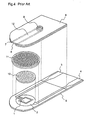
- FIG. 4 is an exploded perspective view illustrating a conventional biosensor for measuring a blood sugar level as described above.
- a working electrode 1 and a counter electrode 2 are formed by printing on an insulating support 5 comprising polyethylene terephthalate or the like, a reagent layer 10 including glucose oxidase and an electron acceptor is formed on the working and counter electrodes 1 and 2 and, further, a surfactant layer 11 comprising yolk lecithin or the like is formed on the reagent layer 10 .
- a spacer 7 having a long and narrow cut-out portion on the electrodes and the reagent layer 10 , and a cover 6 having an air hole are bonded together onto the insulating support 5 so as to form a cavity 12 in which a specific amount of sampled blood is made to react with the reagent layer 10 , and a current value that is generated by such a reaction is detected with the working and counter electrodes 1 and 2 .
- blood is drawn from a suction inlet 8 into the cavity 12 by capillary phenomenon, and is guided to the position where the electrodes and the reagent layer 10 are presently located. Then, a current value that is generated by a reaction between the blood and the reagent on the electrodes is read by an external measuring apparatus (not shown) that is connected to the biosensor through leads 3 and 4 , and a blood sugar level in the blood is obtained according to the current value.
- the surfactant layer 11 prevents the reagent layer 10 from dissolving into the blood, and this causes variations in the sensitivity of the sensor or in the measured value, thereby resulting in a detrimental effect on the performance of the sensor.
- the formation of the surfactant layer 11 on the reagent layer 10 requires a step of applying and spreading a solution including a surfactant so as to cover the reagent layer 10 , and a step of drying the surfactant layer. Therefore, the process of manufacturing the biosensor takes a much greater time, which results in poor productivity.
- An object of the present invention is to provide a biosensor which can promote the flow of blood into the cavity so as to quickly and sufficiently draw the blood into the cavity without forming a surfactant layer on the reagent layer.
- the surface itself of at least a portion of side walls of the sensor facing the cavity has hydrophilicity.
- the biosensor constructed as described above since at least a portion of the side walls of the sensor, which side walls face the cavity into which the liquid sample is drawn by capillary phenomenon, has hydrophilicity at its surface, suction of the liquid sample can be promoted without providing a surfactant layer on the reagent that reacts with the liquid sample. Accordingly, the process of manufacturing the sensor can be simplified.
- the side walls of the sensor facing the cavity are made of a resin material in which a surfactant is mixed.
- the side walls having hydrophilicity are made of a resin material in which a surfactant is mixed, suction of the liquid sample can be promoted without providing a surfactant layer on the reagent that reacts with the liquid sample, and the process of manufacturing the sensor can be simplified.
- the amount of the surfactant to be mixed is 0.01 weight % or more of the resin material.
- the side walls of the sensor facing the cavity are made of a resin material into which a surfactant of 0.01 weight % or more of the resin material is mixed, a sufficient blood suction promoting effect can be achieved.
- the side walls of the sensor facing the cavity are made of a film whose surface is covered with a surfactant.
- the side walls of the sensor having hydrophilicity are made of a film whose surface is covered with a surfactant, suction of the liquid sample can be promoted without providing a surfactant layer on the reagent that reacts with the liquid sample and, accordingly, the process of manufacturing the sensor can be simplified.
- the side walls of the sensor facing the cavity are made of a film whose surface is covered with a resin having a hydrophilic polar group.
- the side walls of the sensor having hydrophilicity are made of a film whose surface is covered with a resin having a hydrophilic polar group, suction of the liquid sample can be promoted without providing a surfactant layer on the reagent that reacts with the liquid sample and, accordingly, the process of manufacturing the sensor can be simplified.
- the thickness of the surfactant or the resin having a hydrophilic polar group, which covers the film is several tens of angstroms or more.
- the side walls of the sensor facing the cavity are made of a film that is covered with the surfactant or the resin having a hydrophilic polar group, a sufficient blood suction promoting effect can be achieved.
- the surface of at least a portion of the side walls forming the cavity is chemically reformed.
- the surface of at least a portion of the side walls forming the cavity is chemically reformed so as to form the side walls of the sensor having hydrophilicity, suction of the liquid sample can be promoted without providing a surfactant layer on the reagent that reacts with the liquid sample, and accordingly, the process of manufacturing the sensor can be simplified.
- a hydrophilic functional group is formed on the surface of at least a portion of the side walls facing the cavity by subjecting the surface to any of the following treatments: plasma discharge, coupling reaction, ozone treatment, and UV treatment.
- the surface of at least a portion of the side walls forming the cavity is subjected to any of the following chemical surface treatments: plasma discharge, coupling reaction, ozone treatment, and UV treatment, thereby forming a hydrophilic functional group on the surface. Therefore, the surface of at least a portion of the side walls facing the cavity can have hydrophilicity.
- the surface of at least a portion of the side walls facing the cavity is made of a rough surface.
- the surface of at least a portion of the side walls forming the cavity is roughened so as to form the side walls of the sensor having hydrophilicity, suction of the liquid sample can be promoted without providing a surfactant layer on the reagent that reacts with the liquid sample, and, accordingly, the process of manufacturing the sensor can be simplified.
- a rough surface is formed at the surface of at least a portion of the side walls facing the cavity by subjecting the surface to any of the following treatments: sand blasting, electric discharge, non-glare treatment, mat treatment, and chemical plating.
- the surface of at least a portion of the side walls forming the cavity is subjected to any of the following treatments: sand blasting, electric discharge, non-glare treatment, mat treatment, and chemical plating, thereby forming a rough surface. Therefore, the surface of at least a portion of the side walls facing the cavity can have hydrophilicity.
- the surface of the support, on which the reagent that reacts with the liquid sample is formed also has hydrophilicity.
- the biosensor constructed as described above not only the surface of at least a portion of the side walls forming the cavity but also the surface of the support on which the reagent that reacts with the liquid sample is formed, have hydrophilicity. Therefore, the area of the portion having hydrophilicity in the side walls facing the cavity is increased, whereby the liquid sample can be drawn with higher efficiency.
- the surface of the support on which electrodes that detect the reaction between the liquid sample and the reagent are formed also has hydrophilicity.
- the biosensor constructed as described above not only the surface of at least a portion of the side walls forming the cavity but also the surface of the support on which the electrodes for detecting the reaction between the liquid sample and the reagent are formed have hydrophilicity. Therefore, the adhesion of the electrodes to the support on which the electrodes are formed is improved, and the problem of electrode peeling is solved, whereby the reliability of the sensor is improved.
- the surface of the support is made of a rough surface, and the level of the rough surface to be formed is 0.001 ⁇ m to 1 ⁇ m.
- the adhesion is improved.
- FIG. 1 is an exploded perspective view illustrating a biosensor for measuring a blood sugar level according to embodiments of the present invention.
- FIG. 2 is a graph showing the result of a comparison of the sensitivities to blood between a sensor according to Example 1 of the present invention and a conventional sensor.
- FIG. 3 is a graph showing the result of a comparison of the sensitivities to blood between a sensor according to Example 2 of the present invention and a conventional sensor.
- FIG. 4 is an exploded perspective view illustrating a conventional biosensor for measuring a blood sugar level.
- FIG. 1 a first embodiment of the present invention will be described with reference to FIG. 1 .
- FIG. 1 is an exploded perspective view of a biosensor according to the first embodiment of the present invention, and this biosensor is different from the conventional biosensor in that the surfactant layer 11 that is formed on the reaction reagent layer 10 of the conventional biosensor is dispensed with.
- the surfactant layer 11 As a substitute for the surfactant layer 11 , at least a portion of the side walls facing the cavity 12 into which blood is drawn, i.e., at least a portion of parts of the spacer 7 and the cover 6 , which parts face the cavity 12 , is made to itself have hydrophilicity so as to promote the drawing of the blood.
- An insulating film is formed by mixing a chemical having surface activity such as a surfactant or the like into a material such as polyethylene terephthalate, polycarbonate or the like, and the cover 6 and the spacer 7 are constituted by the insulating film. Thereby, the wettability of the side walls of the cavity 12 is increased, and the blood that is sampled from the suction inlet 8 can be quickly and reliably drawn into the cavity 12 .
- the kinds of surfactants which can be expected to have the above-mentioned effects when being mixed into the insulating film are as follows: anionic surfactants such as carboxylate, sulfonate, ester phosphate, and the like; cationic surfactants such as primary amine salt, secondary amine salt, tertiary amine salt, quaternary ammonium salt, and the like; ampholytic surfactants such as amino-acid base surfactants, betaine base surfactants, and the like; and non-ionic surfactants such as polyethylene glycol base surfactants, polyalcohol base surfactants, and the like.
- anionic surfactants such as carboxylate, sulfonate, ester phosphate, and the like
- cationic surfactants such as primary amine salt, secondary amine salt, tertiary amine salt, quaternary ammonium salt, and the like
- ampholytic surfactants such as amino-acid base surfactants, betaine base sur
- the materials of the cover 6 and the spacer 7 into which the above-mentioned surfactants can be mixed there are, besides those already mentioned above, polybutylene terephthalate, polyamide, polyvinyl chloride, polyvinylidene chloride, polyimide, nylon, and the like.
- the side walls facing the cavity 12 into which blood is drawn i.e., the portions of the cover 6 and the spacer 7 facing the cavity 12
- the side walls facing the cavity 12 into which blood is drawn are made to have hydrophilicity by mixing a chemical having surface activity such as a surfactant or the like into the material itself of the cover 6 and the spacer 7 . Therefore, the wettability of the side walls of the cavity 12 is increased, whereby the blood that is sampled from the suction inlet B can be quickly and reliably drawn into the cavity 12 . Accordingly, the surfactant layer 11 of the conventional biosensor on the reagent layer 10 can be dispensed with, and the process of manufacturing the biosensor can be simplified.
- the blood suction promoting effect obtained by mixing the surfactant into the insulating base material to be the cover 6 and the spacer 7 is sufficiently recognized when the surfactant of 0.01 weight % or more of the insulating base material is added.
- FIG. 1 a second embodiment of the present invention will be described with reference to FIG. 1 .
- a surfactant is mixed into the material itself of the cover 6 and the spacer 7 so as to make the portions of the cover 6 and the spacer 7 facing the cavity 12 have hydrophilicity.
- any one or more of the surfactants described above for the first embodiment is applied onto an insulating film comprising polyethylene terephthalate, polycarbonate, or the like and made to be a base material of the cover 6 and the spacer 7 , or a resin having a hydrophilic polar group at its surface is laminated on the insulating film, so as to coat the insulating film with the surfactant or the resin, thereby making the portions of the cover 6 and the spacer 7 facing the cavity 12 have hydrophilicity.
- the resin having a hydrophilic polar group there are acrylic resin, polyester resin, urethan resin, and the like.
- the base material is not restricted to the above-mentioned insulating film comprising polyethylene terephthalate or polycarbonate, but other materials such as polybutylene terephthalate, polyamide, polyvinyl chloride, polyvinylidene chloride, polyimide, and nylon may be employed.
- the hydrophilicity of the side walls of the cavity 12 can be increased so as to enhance the wettability of the side walls by subjecting the surface of the insulating film comprising polyethylene terephthalate, polycarbonate, or the like and to be the base material of the cover 6 and the spacer 7 , to primer treatment by using an organotitanium compound, polyethylene imine compound, isocyanate compound, or the like.
- a surfactant is applied onto the insulating film to be the base material of the cover 6 and the spacer 7 , or a resin having a hydrophilic polar group at its surface is laminated on the insulating film so as to coat the surfaces of the cover 6 and the spacer 7 with the surfactant or the resin, whereby the side walls facing the cavity 12 into which blood is drawn, i.e., the portions of the cover 6 and the spacer 7 facing the cavity 12 , have hydrophilicity. Therefore, the wettability of the side walls of the cavity 12 is increased, whereby the blood that is sampled from the suction inlet 6 can be quickly and reliably drawn into the cavity 12 . Accordingly, the surfactant layer 11 of the conventional biosensor on the reagent layer 10 is dispensed with, whereby the process of manufacturing the biosensor can be simplified.
- the blood suction promoting effect is recognized when the thickness of the surfactant layer that is applied onto the insulating film as the base material of the cover 6 and the spacer 7 or the thickness of the resin layer having a hydrophilic polar radial to be laminated is several tens of angstroms or more. However, in order to sustain the above-mentioned effect for long hours, the thickness is desired to be several hundreds of angstroms or more.
- FIG. 1 a third embodiment of the present invention will be described with reference to FIG. 1 .
- a surfactant is mixed into the material itself of the cover 6 and the spacer 7 so as to make the portions of the cover 6 and the spacer 7 facing the cavity 12 have hydrophilicity.
- the surfaces of the cover 6 and the spacer 7 facing the cavity 12 are chemically treated or processed so as to make the portions of the cover 6 and the spacer 7 facing the cavity 12 have hydrophilicity.
- a hydrophilic functional group such as carboxyl group, hydroxyl group, carbonyl group or the like is formed on the surfaces of the cover 6 and the spacer 7 facing the cavity 12 , whereby the surface of the material of the cover 6 and the spacer 7 is chemically reformed so as to increase the surface wettability.
- the materials of the cover 6 and the spacer 7 which can be subjected to the above-mentioned chemical treatment, there are polybutylene terephthalate, polyamide, polyvinyl chloride, polyvinylidene chloride, polyimide, nylon, and the like in addition to the above-mentioned polyethylene terephthalate and polycarbonate.
- the surfaces of the cover 6 and the spacer 7 facing the cavity 12 into which the blood is drawn are subjected to the chemical treatment or the processing for chemically reforming the surfaces, whereby the portions of the cover 6 and the spacer 7 facing the cavity 12 have hydrophilicity. Therefore, the wettability of the side walls of the cavity 12 is increased, whereby the blood that is sampled from the suction inlet 8 can be quickly and reliably drawn into the cavity 12 . Accordingly, the surfactant layer 11 of the conventional biosensor on the reagent layer 10 is dispensed with, whereby the process of manufacturing the biosensor can be simplified.
- FIG. 1 a fourth embodiment of the present invention will be described with reference to FIG. 1 .
- a surfactant is mixed into the material itself of the cover 6 and the spacer 7 so as to make the portions of the cover 6 and the spacer 7 facing the cavity 12 have hydrophilicity.
- the surfaces of the cover 6 and the spacer 7 facing the cavity 12 are roughened so as to form a fine and continuous rough-texture (asperities) on the material surface, thereby making the portions of the cover 6 and the spacer 7 facing the cavity 12 have hydrophilicity.
- the materials of the cover 6 and the spacer 7 on which such treatment can be performed there are polybutylene terephthalate, polyamide, polyvinyl chloride, polyvinylidene chloride, polyimide, nylon, and the like in addition to the above-mentioned polyethylene terephthalate and polycarbonate.
- a fine and continuous rough-texture is formed on the surfaces of the cover 6 and the spacer 7 facing the cavity 12 so as to make the portions of the cover 6 and the spacer 7 facing the cavity 12 have hydrophilicity. Therefore, the wettability of the side walls of the cavity 12 is increased, whereby the blood that is sampled from the suction inlet 8 can be quickly and reliably drawn into the cavity 12 . Accordingly, the surfactant layer 11 of the conventional biosensor on the reagent layer 10 is dispensed with, whereby the process of manufacturing the biosensor is simplified.
- FIG. 1 a fifth embodiment of the present invention will be described with reference to FIG. 1 .
- the construction of a biosensor according to the fifth embodiment will be described with reference to FIG. 1 .
- the side walls of the cavity 12 i.e., the portions of the cover 6 and the spacer 7 facing the cavity 12 , are processed so as to have hydrophilicity.
- the cover 6 and spacer 7 not only the cover 6 and spacer 7 but also the surface of the insulating support 5 on which the working electrode 1 , the counter electrode 2 , and the reagent layer 10 are formed, are subjected to any of the hydrophilic processes described above.
- the insulating support 5 is subjected the hydrophilic process as described for any of the first to fourth embodiments, whereby suction of the liquid sample can be further promoted.
- a biosensor as shown in FIG. 1 when a biosensor as shown in FIG. 1 is obtained by die-cutting an insulating support 5 with a press or the like according to the outline of the sensor after bonding onto the insulating support 5 on which plural electrodes and reagent layers 10 are formed, a spacer 7 having cut-out grooves for forming cavities 12 in positions corresponding to the respective electrodes and reagent layers, and a cover 6 having air holes 9 in the corresponding positions, the electrodes peel off from the insulating support 5 or the electrodes are cracked due to a shock that occurs when the insulating support 5 is die-cut.
- the electrodes are formed by printing a paste comprising a conductive material on the insulating support 5 , where the polarity of insulating support 5 is inherently very small. Therefore, the insulating support 5 is also subjected to the hydrophilic process as described for any of the first to fourth embodiments to make the material surface of the insulating support 5 , the surface of which inherently has a very small polarity, have a polarity, whereby spread and adhesion of the paste which comprises a conductive material and which is used as a material of the electrodes are improved. Therefore, the electrodes are prevented from peeling off from the insulating support 5 , or from being cracked.
- suction of the blood that is sampled from the suction inlet 8 is further promoted as compared with the case where only the cover 6 and the spacer 7 are subjected to the hydrophilic process.
- the insulating support 5 is subjected to the hydrophilic process before the formation of the electrodes so as to make the insulating support 5 have a polarity, adhesion of the electrodes to the insulating support 5 is increased, whereby peeling-off of the electrodes from the insulating support 5 and cracking of the electrodes, which have occurred during manufacturing of the biosensor (a blood sugar measuring sensor), are avoided.
- the level of the rough surface (asperities) at which the effect of adhesion can be expected is within a range of 0.001 ⁇ m-1 ⁇ m, where 0.01 ⁇ m-0.1 ⁇ m are especially desirable.
- an electrode layer comprising a working electrode 1 and a counter electrode 2 is formed by screen printing, and a reagent layer 10 including an enzyme (glucose oxidase) and an electron acceptor (potassium ferricyanide) is formed on the electrode layer.
- a reagent layer 10 including an enzyme (glucose oxidase) and an electron acceptor (potassium ferricyanide) is formed on the electrode layer.
- a spacer 7 comprising polyethylene terephthalate is bonded to a cover 6 comprising polyethylene terephthalate in which about 1% of alkylbenzene sulfonate, as an anionic surfactant, is blended, thereby fabricating a blood sugar measuring sensor having a groove as a capillary tube into which blood is drawn.
- Table 1 shows the blood suction ability of the sensor fabricated in this manner.
- a suction inlet 8 having a height of 0.17 mm and a width of 2.0 mm is used.
- Each numeric value in Table 1 indicates a time that is required until the groove, as a capillary tube into which blood is drawn, is completely filled with the blood, under hostile environments (environmental temperature: 5° C. hematocrit: 65%), and the result proves that the same blood suction promoting effect as the blood suction promoting effect that is obtained by the conventional sensor is achieved.
- the indices of wettability (surface tension) of the insulating support 5 and the cover 6 which comprise polyethylene terephthalate used in Example 1 are 48 dyn/cm when they are not processed
- the index of the wettability at the surface of the insulating support 5 after being subjected to corona discharge and the index of the wettability at the surface of the cover 6 into which alkylbenzene sulfonate is blended are 54 dyn/cm or more, whereby this result indicates that sufficient wettability for promoting blood suction is secured.
- FIG. 2 shows the result of a comparison of the sensor sensitivities at the blood glucose concentrations of 53-992 mg/dl.
- the sensitivity of the sensor of Example 1 is about 5% higher than the sensitivity of the conventional sensor. This attests to the result where the non-use of the surfactant layer 11 increases the solubility of the reagent layer 10 that reacts with the blood.
- a checker pattern having 100 squares at 1 mm intervals is formed according to JISK5400 (general test method for coating; adhesion; checker-pattern taping method), and the degree of electrode peeling-off is checked with an adhesive cellophane tape.
- JISK5400 general test method for coating; adhesion; checker-pattern taping method
- the result is as follows. While peeling-off of electrodes occurs at frequency of 5/100 squares in the conventional sensor performing no corona discharge, it occurs at frequency of 0/100 squares in the sensor of Example 1; that is, a clearly significant difference is confirmed.
- an electrode layer comprising a working electrode 1 and a counter electrode 2 is formed by screen printing, and a reagent layer 10 including an enzyme (glucose oxidase) and an electron acceptor (potassium ferricyanide) is formed on the electrode layer.
- a reagent layer 10 including an enzyme (glucose oxidase) and an electron acceptor (potassium ferricyanide) is formed on the electrode layer.
- a spacer 7 comprising polyethylene terephthalate is bonded to a cover 6 comprising a compound film (the index of surface wettability: 54 dyn/cm or more) which is obtained by laminating a polyester base resin having a hydrophilic polar group on polyethylene terephthalate, thereby fabricating a blood sugar measuring sensor having a groove as a capillary tube into which blood is drawn, and evaluations similar to those of Example 1 are executed.
- Table 3 shows the result of a comparison of the blood suction rates between the sensor fabricated as described above according the Example 2 and the conventional sensor
- FIG. 3 shows the result of a comparison of the sensor sensitivities at the blood glucose concentrations of 53-992 mg/dl
- a biosensor according to the present invention is available as a biosensor which improves sensitivity and which reduces variations when analyzing a specific component in a liquid sample that is drawn into a cavity of the sensor by capillary phenomenon.
Abstract
Description
| TABLE 1 | |||
| conventional sensor | sensor of Example 1 | ||
| 1 | 0.54 | 0.68 |
| 2 | 0.69 | 0.58 |
| 3 | 0.69 | 0.72 |
| 4 | 0.63 | 0.65 |
| 5 | 0.72 | 0.64 |
| average (sec) | 0.65 | 0.65 |
| comparison of blood suction rates (n = 5) | ||
| TABLE 2 | ||
| glucose | ||
| concentration | conventional sensor | sensor of Example 1 |
| 53 mg/dl | 6.25% | 3.79% |
| 83 mg/dl | 3.15% | 1.67% |
| 253 mg/dl | 3.49% | 1.53% |
| 488 mg/dl | 2.24% | 0.60% |
| 596 mg/dl | 2.49% | 1.86% |
| 992 mg/dl | 2.23% | 2.11% |
| comparison of sensor accuracy (CV values) | ||
| TABLE 3 | |||
| conventional sensor | sensor of Example 2 | ||
| 1 | 0.54 | 0.62 |
| 2 | 0.69 | 0.55 |
| 3 | 0.69 | 0.68 |
| 4 | 0.63 | 0.60 |
| 5 | 0.72 | 0.69 |
| average (sec) | 0.65 | 0.63 |
| comparison of blood suction rates (n = 5) | ||
| TABLE 4 | ||
| glucose | ||
| concentration | conventional sensor | sensor of Example 2 |
| 53 mg/dl | 6.25% | 3.88% |
| 83 mg/dl | 3.15% | 2.17% |
| 253 mg/dl | 3.49% | 1.22% |
| 488 mg/dl | 2.24% | 1.60% |
| 596 mg/dl | 2.49% | 1.56% |
| 992 mg/dl | 2.23% | 2.05% |
| comparison of sensor accuracy (CV values) | ||
Claims (13)
Applications Claiming Priority (4)
| Application Number | Priority Date | Filing Date | Title |
|---|---|---|---|
| JP34449599A JP2001159618A (en) | 1999-12-03 | 1999-12-03 | Biosensor |
| JP11-344495 | 1999-12-03 | ||
| JP11344495 | 1999-12-03 | ||
| PCT/JP2000/008508 WO2001040788A1 (en) | 1999-12-03 | 2000-12-01 | Biosensor |
Publications (2)
| Publication Number | Publication Date |
|---|---|
| US20040016642A1 US20040016642A1 (en) | 2004-01-29 |
| US6830669B2 true US6830669B2 (en) | 2004-12-14 |
Family
ID=18369721
Family Applications (1)
| Application Number | Title | Priority Date | Filing Date |
|---|---|---|---|
| US09/890,761 Expired - Lifetime US6830669B2 (en) | 1999-12-03 | 2000-12-01 | Biosensor |
Country Status (6)
| Country | Link |
|---|---|
| US (1) | US6830669B2 (en) |
| EP (1) | EP1156325B1 (en) |
| JP (1) | JP2001159618A (en) |
| CN (1) | CN1243976C (en) |
| DE (1) | DE60026352T2 (en) |
| WO (1) | WO2001040788A1 (en) |
Cited By (85)
| Publication number | Priority date | Publication date | Assignee | Title |
|---|---|---|---|---|
| US20040029177A1 (en) * | 2001-08-09 | 2004-02-12 | Masataka Nadaoka | Biosensor and measurement method |
| US20040171968A1 (en) * | 2001-07-13 | 2004-09-02 | Koji Katsuki | Analyzing apparatus, piercing element integrally installed body for temperature measuring device with analyzing apparatus, and body fluid sampling apparatus |
| US20040213986A1 (en) * | 2003-04-22 | 2004-10-28 | Kim Ho-Cheol | Patterned, high surface area substrate with hydrophilic/hydrophobic contrast, and method of use |
| US20040214110A1 (en) * | 2003-04-22 | 2004-10-28 | Kim Ho-Cheol | Patterned substrate with hydrophilic/hydrophobic contrast, and method of use |
| US20060147343A1 (en) * | 2003-06-19 | 2006-07-06 | Arkray, Inc. | Analyzer instrument whith liquid storage portion |
| US20060175199A1 (en) * | 2005-02-10 | 2006-08-10 | Bionime Corporation | Electrochemical sensor strip and manufacturing method thereof |
| US20060243589A1 (en) * | 2003-02-14 | 2006-11-02 | Shigeru Doi | Analyzing tool with knob part |
| US7648468B2 (en) | 2002-04-19 | 2010-01-19 | Pelikon Technologies, Inc. | Method and apparatus for penetrating tissue |
| US7666149B2 (en) | 1997-12-04 | 2010-02-23 | Peliken Technologies, Inc. | Cassette of lancet cartridges for sampling blood |
| US7674232B2 (en) | 2002-04-19 | 2010-03-09 | Pelikan Technologies, Inc. | Method and apparatus for penetrating tissue |
| US7682318B2 (en) | 2001-06-12 | 2010-03-23 | Pelikan Technologies, Inc. | Blood sampling apparatus and method |
| US7699791B2 (en) | 2001-06-12 | 2010-04-20 | Pelikan Technologies, Inc. | Method and apparatus for improving success rate of blood yield from a fingerstick |
| US7708701B2 (en) | 2002-04-19 | 2010-05-04 | Pelikan Technologies, Inc. | Method and apparatus for a multi-use body fluid sampling device |
| US7717863B2 (en) | 2002-04-19 | 2010-05-18 | Pelikan Technologies, Inc. | Method and apparatus for penetrating tissue |
| US7727467B2 (en) | 2003-06-20 | 2010-06-01 | Roche Diagnostics Operations, Inc. | Reagent stripe for test strip |
| US7731729B2 (en) | 2002-04-19 | 2010-06-08 | Pelikan Technologies, Inc. | Method and apparatus for penetrating tissue |
| US7749174B2 (en) | 2001-06-12 | 2010-07-06 | Pelikan Technologies, Inc. | Method and apparatus for lancet launching device intergrated onto a blood-sampling cartridge |
| US7780631B2 (en) | 1998-03-30 | 2010-08-24 | Pelikan Technologies, Inc. | Apparatus and method for penetration with shaft having a sensor for sensing penetration depth |
| US20100255589A1 (en) * | 2007-10-30 | 2010-10-07 | Panasonic Corporation | Analyzing device, analyzing apparatus using the device, and analyzing method |
| US7822454B1 (en) | 2005-01-03 | 2010-10-26 | Pelikan Technologies, Inc. | Fluid sampling device with improved analyte detecting member configuration |
| US7833171B2 (en) | 2002-04-19 | 2010-11-16 | Pelikan Technologies, Inc. | Method and apparatus for penetrating tissue |
| US7850622B2 (en) | 2001-06-12 | 2010-12-14 | Pelikan Technologies, Inc. | Tissue penetration device |
| US7850621B2 (en) | 2003-06-06 | 2010-12-14 | Pelikan Technologies, Inc. | Method and apparatus for body fluid sampling and analyte sensing |
| US7862520B2 (en) | 2002-04-19 | 2011-01-04 | Pelikan Technologies, Inc. | Body fluid sampling module with a continuous compression tissue interface surface |
| US7874994B2 (en) | 2002-04-19 | 2011-01-25 | Pelikan Technologies, Inc. | Method and apparatus for penetrating tissue |
| US7892185B2 (en) | 2002-04-19 | 2011-02-22 | Pelikan Technologies, Inc. | Method and apparatus for body fluid sampling and analyte sensing |
| US7892183B2 (en) | 2002-04-19 | 2011-02-22 | Pelikan Technologies, Inc. | Method and apparatus for body fluid sampling and analyte sensing |
| US7901365B2 (en) | 2002-04-19 | 2011-03-08 | Pelikan Technologies, Inc. | Method and apparatus for penetrating tissue |
| US7901362B2 (en) | 2002-04-19 | 2011-03-08 | Pelikan Technologies, Inc. | Method and apparatus for penetrating tissue |
| US7909777B2 (en) | 2002-04-19 | 2011-03-22 | Pelikan Technologies, Inc | Method and apparatus for penetrating tissue |
| US7909778B2 (en) | 2002-04-19 | 2011-03-22 | Pelikan Technologies, Inc. | Method and apparatus for penetrating tissue |
| US7914465B2 (en) | 2002-04-19 | 2011-03-29 | Pelikan Technologies, Inc. | Method and apparatus for penetrating tissue |
| US7976476B2 (en) | 2002-04-19 | 2011-07-12 | Pelikan Technologies, Inc. | Device and method for variable speed lancet |
| US7988645B2 (en) | 2001-06-12 | 2011-08-02 | Pelikan Technologies, Inc. | Self optimizing lancing device with adaptation means to temporal variations in cutaneous properties |
| US8007446B2 (en) | 2002-04-19 | 2011-08-30 | Pelikan Technologies, Inc. | Method and apparatus for penetrating tissue |
| US8071030B2 (en) | 2003-06-20 | 2011-12-06 | Roche Diagnostics Operations, Inc. | Test strip with flared sample receiving chamber |
| US8079960B2 (en) | 2002-04-19 | 2011-12-20 | Pelikan Technologies, Inc. | Methods and apparatus for lancet actuation |
| US8148164B2 (en) | 2003-06-20 | 2012-04-03 | Roche Diagnostics Operations, Inc. | System and method for determining the concentration of an analyte in a sample fluid |
| US8197421B2 (en) | 2002-04-19 | 2012-06-12 | Pelikan Technologies, Inc. | Method and apparatus for penetrating tissue |
| US8221334B2 (en) | 2002-04-19 | 2012-07-17 | Sanofi-Aventis Deutschland Gmbh | Method and apparatus for penetrating tissue |
| US8262614B2 (en) | 2003-05-30 | 2012-09-11 | Pelikan Technologies, Inc. | Method and apparatus for fluid injection |
| US8267870B2 (en) | 2002-04-19 | 2012-09-18 | Sanofi-Aventis Deutschland Gmbh | Method and apparatus for body fluid sampling with hybrid actuation |
| US8282576B2 (en) | 2003-09-29 | 2012-10-09 | Sanofi-Aventis Deutschland Gmbh | Method and apparatus for an improved sample capture device |
| US8287703B2 (en) | 1999-10-04 | 2012-10-16 | Roche Diagnostics Operations, Inc. | Biosensor and method of making |
| US8337421B2 (en) | 2001-06-12 | 2012-12-25 | Sanofi-Aventis Deutschland Gmbh | Tissue penetration device |
| US8360993B2 (en) | 2005-09-30 | 2013-01-29 | Intuity Medical, Inc. | Method for body fluid sample extraction |
| US8360992B2 (en) | 2002-04-19 | 2013-01-29 | Sanofi-Aventis Deutschland Gmbh | Method and apparatus for penetrating tissue |
| US8435190B2 (en) | 2002-04-19 | 2013-05-07 | Sanofi-Aventis Deutschland Gmbh | Method and apparatus for penetrating tissue |
| US20130112573A1 (en) * | 2010-05-07 | 2013-05-09 | Exacsys Limited | Devices and methods for testing analytes |
| US8556829B2 (en) | 2002-04-19 | 2013-10-15 | Sanofi-Aventis Deutschland Gmbh | Method and apparatus for penetrating tissue |
| US8574895B2 (en) | 2002-12-30 | 2013-11-05 | Sanofi-Aventis Deutschland Gmbh | Method and apparatus using optical techniques to measure analyte levels |
| US8641644B2 (en) | 2000-11-21 | 2014-02-04 | Sanofi-Aventis Deutschland Gmbh | Blood testing apparatus having a rotatable cartridge with multiple lancing elements and testing means |
| US8652831B2 (en) | 2004-12-30 | 2014-02-18 | Sanofi-Aventis Deutschland Gmbh | Method and apparatus for analyte measurement test time |
| US8668656B2 (en) | 2003-12-31 | 2014-03-11 | Sanofi-Aventis Deutschland Gmbh | Method and apparatus for improving fluidic flow and sample capture |
| US8679853B2 (en) | 2003-06-20 | 2014-03-25 | Roche Diagnostics Operations, Inc. | Biosensor with laser-sealed capillary space and method of making |
| US8702624B2 (en) | 2006-09-29 | 2014-04-22 | Sanofi-Aventis Deutschland Gmbh | Analyte measurement device with a single shot actuator |
| US8721671B2 (en) | 2001-06-12 | 2014-05-13 | Sanofi-Aventis Deutschland Gmbh | Electric lancet actuator |
| US8784335B2 (en) | 2002-04-19 | 2014-07-22 | Sanofi-Aventis Deutschland Gmbh | Body fluid sampling device with a capacitive sensor |
| US8801631B2 (en) | 2005-09-30 | 2014-08-12 | Intuity Medical, Inc. | Devices and methods for facilitating fluid transport |
| US8828203B2 (en) | 2004-05-20 | 2014-09-09 | Sanofi-Aventis Deutschland Gmbh | Printable hydrogels for biosensors |
| US8919605B2 (en) | 2009-11-30 | 2014-12-30 | Intuity Medical, Inc. | Calibration material delivery devices and methods |
| US8965476B2 (en) | 2010-04-16 | 2015-02-24 | Sanofi-Aventis Deutschland Gmbh | Tissue penetration device |
| US8969097B2 (en) | 2005-06-13 | 2015-03-03 | Intuity Medical, Inc. | Analyte detection devices and methods with hematocrit-volume correction and feedback control |
| US9046479B2 (en) * | 2008-06-24 | 2015-06-02 | Panasonic Healthcare Holdings Co., Ltd. | Biosensor, method of producing the same and detection system comprising the same |
| US9095292B2 (en) | 2003-03-24 | 2015-08-04 | Intuity Medical, Inc. | Analyte concentration detection devices and methods |
| US9144401B2 (en) | 2003-06-11 | 2015-09-29 | Sanofi-Aventis Deutschland Gmbh | Low pain penetrating member |
| US20150276671A1 (en) * | 2012-07-20 | 2015-10-01 | Apex Biotechnology Corp. | Electrode strip and sensor strip and manufacture method thereof and system thereof |
| US9226699B2 (en) | 2002-04-19 | 2016-01-05 | Sanofi-Aventis Deutschland Gmbh | Body fluid sampling module with a continuous compression tissue interface surface |
| US9248267B2 (en) | 2002-04-19 | 2016-02-02 | Sanofi-Aventis Deustchland Gmbh | Tissue penetration device |
| US9314194B2 (en) | 2002-04-19 | 2016-04-19 | Sanofi-Aventis Deutschland Gmbh | Tissue penetration device |
| US9351680B2 (en) | 2003-10-14 | 2016-05-31 | Sanofi-Aventis Deutschland Gmbh | Method and apparatus for a variable user interface |
| US9375169B2 (en) | 2009-01-30 | 2016-06-28 | Sanofi-Aventis Deutschland Gmbh | Cam drive for managing disposable penetrating member actions with a single motor and motor and control system |
| US9386944B2 (en) | 2008-04-11 | 2016-07-12 | Sanofi-Aventis Deutschland Gmbh | Method and apparatus for analyte detecting device |
| US9427532B2 (en) | 2001-06-12 | 2016-08-30 | Sanofi-Aventis Deutschland Gmbh | Tissue penetration device |
| US9636051B2 (en) | 2008-06-06 | 2017-05-02 | Intuity Medical, Inc. | Detection meter and mode of operation |
| US9775553B2 (en) | 2004-06-03 | 2017-10-03 | Sanofi-Aventis Deutschland Gmbh | Method and apparatus for a fluid sampling device |
| US9782114B2 (en) | 2011-08-03 | 2017-10-10 | Intuity Medical, Inc. | Devices and methods for body fluid sampling and analysis |
| US9795747B2 (en) | 2010-06-02 | 2017-10-24 | Sanofi-Aventis Deutschland Gmbh | Methods and apparatus for lancet actuation |
| US9820684B2 (en) | 2004-06-03 | 2017-11-21 | Sanofi-Aventis Deutschland Gmbh | Method and apparatus for a fluid sampling device |
| US9833183B2 (en) | 2008-05-30 | 2017-12-05 | Intuity Medical, Inc. | Body fluid sampling device—sampling site interface |
| US20170347935A1 (en) * | 2013-03-15 | 2017-12-07 | Ortho-Clinical Diagnostics, Inc. | Rotatable disk-shaped fluid sample collection device |
| US10330667B2 (en) | 2010-06-25 | 2019-06-25 | Intuity Medical, Inc. | Analyte monitoring methods and systems |
| US10383556B2 (en) | 2008-06-06 | 2019-08-20 | Intuity Medical, Inc. | Medical diagnostic devices and methods |
| US10729386B2 (en) | 2013-06-21 | 2020-08-04 | Intuity Medical, Inc. | Analyte monitoring system with audible feedback |
| US10772550B2 (en) | 2002-02-08 | 2020-09-15 | Intuity Medical, Inc. | Autonomous, ambulatory analyte monitor or drug delivery device |
Families Citing this family (43)
| Publication number | Priority date | Publication date | Assignee | Title |
|---|---|---|---|---|
| US8071384B2 (en) | 1997-12-22 | 2011-12-06 | Roche Diagnostics Operations, Inc. | Control and calibration solutions and methods for their use |
| US7407811B2 (en) * | 1997-12-22 | 2008-08-05 | Roche Diagnostics Operations, Inc. | System and method for analyte measurement using AC excitation |
| US7390667B2 (en) * | 1997-12-22 | 2008-06-24 | Roche Diagnostics Operations, Inc. | System and method for analyte measurement using AC phase angle measurements |
| DE10193213T8 (en) * | 2001-07-27 | 2013-04-25 | Arkray, Inc. | analytical tool |
| EP1448489B1 (en) * | 2001-11-16 | 2010-08-25 | Stefan Ufer | Flexible sensor and method of fabrication |
| AU2003245808A1 (en) * | 2002-04-22 | 2003-11-03 | Bcs Bio- Und Chemosensoren Gmbh | Device for retaining samples for biodetectors |
| DE10234114A1 (en) * | 2002-07-26 | 2004-02-05 | Roche Diagnostics Gmbh | Process for producing a hydrophilic substrate provided with a layer electrode |
| JP4009683B2 (en) * | 2002-09-26 | 2007-11-21 | アークレイ株式会社 | Method for manufacturing analytical tool |
| US6939450B2 (en) * | 2002-10-08 | 2005-09-06 | Abbott Laboratories | Device having a flow channel |
| US7501053B2 (en) * | 2002-10-23 | 2009-03-10 | Abbott Laboratories | Biosensor having improved hematocrit and oxygen biases |
| JP3878993B2 (en) * | 2002-10-31 | 2007-02-07 | アークレイ株式会社 | Analysis tool |
| JP4368804B2 (en) * | 2002-12-02 | 2009-11-18 | ユィロス・パテント・アクチボラグ | Parallel processing of microfluidic devices |
| US7645373B2 (en) * | 2003-06-20 | 2010-01-12 | Roche Diagnostic Operations, Inc. | System and method for coding information on a biosensor test strip |
| US7645421B2 (en) | 2003-06-20 | 2010-01-12 | Roche Diagnostics Operations, Inc. | System and method for coding information on a biosensor test strip |
| US7452457B2 (en) * | 2003-06-20 | 2008-11-18 | Roche Diagnostics Operations, Inc. | System and method for analyte measurement using dose sufficiency electrodes |
| US7597793B2 (en) * | 2003-06-20 | 2009-10-06 | Roche Operations Ltd. | System and method for analyte measurement employing maximum dosing time delay |
| US7718439B2 (en) | 2003-06-20 | 2010-05-18 | Roche Diagnostics Operations, Inc. | System and method for coding information on a biosensor test strip |
| US8206565B2 (en) | 2003-06-20 | 2012-06-26 | Roche Diagnostics Operation, Inc. | System and method for coding information on a biosensor test strip |
| US8058077B2 (en) | 2003-06-20 | 2011-11-15 | Roche Diagnostics Operations, Inc. | Method for coding information on a biosensor test strip |
| AU2003261594A1 (en) * | 2003-09-03 | 2005-03-16 | Jianyuan Chen | An novel test strip, the method for its manufacture and the use thereof |
| US7569126B2 (en) | 2004-06-18 | 2009-08-04 | Roche Diagnostics Operations, Inc. | System and method for quality assurance of a biosensor test strip |
| US7556723B2 (en) * | 2004-06-18 | 2009-07-07 | Roche Diagnostics Operations, Inc. | Electrode design for biosensor |
| US7361958B2 (en) * | 2004-09-30 | 2008-04-22 | Intel Corporation | Nonplanar transistors with metal gate electrodes |
| DE102004049609A1 (en) * | 2004-10-12 | 2006-04-13 | Mitsubishi Polyester Film Gmbh | Polyester film with hydrophilic coating, process for its preparation and its use |
| JP5289666B2 (en) * | 2005-01-24 | 2013-09-11 | 住友電気工業株式会社 | Sensor chip assembly and manufacturing method thereof |
| JP4967389B2 (en) * | 2005-03-29 | 2012-07-04 | 東レ株式会社 | Liquid spreading sheet |
| JP2009014472A (en) * | 2007-07-04 | 2009-01-22 | Toray Ind Inc | Liquid developing sheet and biofluid developing sheet using it |
| EP2017618A1 (en) * | 2007-07-20 | 2009-01-21 | Koninklijke Philips Electronics N.V. | Methods and systems for detecting |
| DE102008006225A1 (en) | 2008-01-25 | 2009-07-30 | Tesa Ag | Biosensor and its production |
| JP5119031B2 (en) * | 2008-04-15 | 2013-01-16 | 株式会社日立ハイテクノロジーズ | Reaction cell manufacturing method and automatic analyzer equipped with reaction cell |
| EP2166352A1 (en) * | 2008-09-17 | 2010-03-24 | F.Hoffmann-La Roche Ag | Device and method for determining an analyte in a fluid sample |
| GB2469071A (en) * | 2009-03-31 | 2010-10-06 | Diamatrix Ltd | Electrochemical test device |
| JP5432575B2 (en) * | 2009-04-21 | 2014-03-05 | グンゼ株式会社 | Biosensor and manufacturing method thereof |
| WO2012046412A1 (en) * | 2010-10-07 | 2012-04-12 | パナソニック株式会社 | Plasmon sensor |
| WO2012075644A1 (en) * | 2010-12-10 | 2012-06-14 | 红电医学科技股份有限公司 | Method for manufacturing fluid-detecting test piece |
| JP6186808B2 (en) * | 2013-03-29 | 2017-08-30 | 大日本印刷株式会社 | Biosensor cover and biosensor |
| JP6149470B2 (en) * | 2013-04-04 | 2017-06-21 | 大日本印刷株式会社 | Biosensor |
| JP6191203B2 (en) * | 2013-04-04 | 2017-09-06 | 大日本印刷株式会社 | Biosensor electrode and biosensor |
| CN104034432B (en) * | 2014-06-18 | 2017-02-15 | 中国人民大学 | Near-infrared sensing chip, preparation method and application thereof |
| MA45299A (en) * | 2015-12-22 | 2018-10-31 | Univ Catalunya Politecnica | ELECTROCHEMICAL SENSOR AND COATING PROCESS, MANUFACTURING PROCESS AND ASSOCIATED USES |
| CN105842309A (en) * | 2016-05-05 | 2016-08-10 | 上海由威通信科技有限公司 | Intelligent blood analyzer |
| KR102169586B1 (en) * | 2018-12-17 | 2020-10-23 | 서울대학교산학협력단 | Strip structure for measuring potassium ions |
| CN115058690A (en) * | 2022-05-23 | 2022-09-16 | 小护士(天津)科技股份有限公司 | Manufacturing method of glucose sensor |
Citations (17)
| Publication number | Priority date | Publication date | Assignee | Title |
|---|---|---|---|---|
| JPS52139778A (en) * | 1976-05-14 | 1977-11-21 | Omron Tateisi Electronics Co | Fixed enzyme membrane |
| JPS5957156A (en) * | 1982-09-28 | 1984-04-02 | Toshiba Corp | Ion selective electrode |
| EP0321736A2 (en) * | 1987-12-23 | 1989-06-28 | Abbott Laboratories | Agglutination reaction device |
| US4849340A (en) * | 1987-04-03 | 1989-07-18 | Cardiovascular Diagnostics, Inc. | Reaction system element and method for performing prothrombin time assay |
| US4929330A (en) * | 1987-03-31 | 1990-05-29 | Daikin Industries, Ltd. | Diffusion-limiting membrane holding means for sensor |
| US4929426A (en) | 1987-11-02 | 1990-05-29 | Biologix, Inc. | Portable blood chemistry measuring apparatus |
| US5120420A (en) | 1988-03-31 | 1992-06-09 | Matsushita Electric Industrial Co., Ltd. | Biosensor and a process for preparation thereof |
| US5437999A (en) | 1994-02-22 | 1995-08-01 | Boehringer Mannheim Corporation | Electrochemical sensor |
| JPH08131791A (en) | 1994-11-15 | 1996-05-28 | Ube Ind Ltd | Film for donating hydrophic effects and manufacture thereof |
| JPH08185999A (en) | 1994-12-28 | 1996-07-16 | Shinko Pantec Co Ltd | Discharge chemical reactor |
| US5759364A (en) * | 1997-05-02 | 1998-06-02 | Bayer Corporation | Electrochemical biosensor |
| US5798031A (en) * | 1997-05-12 | 1998-08-25 | Bayer Corporation | Electrochemical biosensor |
| WO1999030152A1 (en) | 1997-12-05 | 1999-06-17 | Roche Diagnostics Corporation | Improved electrochemical biosensor test strip |
| US6261519B1 (en) * | 1998-07-20 | 2001-07-17 | Lifescan, Inc. | Medical diagnostic device with enough-sample indicator |
| US6287451B1 (en) * | 1999-06-02 | 2001-09-11 | Handani Winarta | Disposable sensor and method of making |
| US6303081B1 (en) * | 1998-03-30 | 2001-10-16 | Orasure Technologies, Inc. | Device for collection and assay of oral fluids |
| EP1152239A1 (en) | 1999-11-15 | 2001-11-07 | Matsushita Electric Industrial Co., Ltd. | Biosensor, method of forming thin-film electrode, and method and apparatus for quantitative determination |
-
1999
- 1999-12-03 JP JP34449599A patent/JP2001159618A/en active Pending
-
2000
- 2000-12-01 CN CN00803403.6A patent/CN1243976C/en not_active Expired - Lifetime
- 2000-12-01 DE DE60026352T patent/DE60026352T2/en not_active Expired - Lifetime
- 2000-12-01 US US09/890,761 patent/US6830669B2/en not_active Expired - Lifetime
- 2000-12-01 EP EP00979044A patent/EP1156325B1/en not_active Expired - Lifetime
- 2000-12-01 WO PCT/JP2000/008508 patent/WO2001040788A1/en active IP Right Grant
Patent Citations (24)
| Publication number | Priority date | Publication date | Assignee | Title |
|---|---|---|---|---|
| JPS52139778A (en) * | 1976-05-14 | 1977-11-21 | Omron Tateisi Electronics Co | Fixed enzyme membrane |
| JPS5957156A (en) * | 1982-09-28 | 1984-04-02 | Toshiba Corp | Ion selective electrode |
| US4929330A (en) * | 1987-03-31 | 1990-05-29 | Daikin Industries, Ltd. | Diffusion-limiting membrane holding means for sensor |
| US4849340A (en) * | 1987-04-03 | 1989-07-18 | Cardiovascular Diagnostics, Inc. | Reaction system element and method for performing prothrombin time assay |
| US4929426A (en) | 1987-11-02 | 1990-05-29 | Biologix, Inc. | Portable blood chemistry measuring apparatus |
| EP0321736A2 (en) * | 1987-12-23 | 1989-06-28 | Abbott Laboratories | Agglutination reaction device |
| US5120420B1 (en) | 1988-03-31 | 1999-11-09 | Matsushita Electric Ind Co Ltd | Biosensor and a process for preparation thereof |
| US5120420A (en) | 1988-03-31 | 1992-06-09 | Matsushita Electric Industrial Co., Ltd. | Biosensor and a process for preparation thereof |
| US5437999A (en) | 1994-02-22 | 1995-08-01 | Boehringer Mannheim Corporation | Electrochemical sensor |
| JPH08131791A (en) | 1994-11-15 | 1996-05-28 | Ube Ind Ltd | Film for donating hydrophic effects and manufacture thereof |
| JPH08185999A (en) | 1994-12-28 | 1996-07-16 | Shinko Pantec Co Ltd | Discharge chemical reactor |
| US5759364A (en) * | 1997-05-02 | 1998-06-02 | Bayer Corporation | Electrochemical biosensor |
| NO981684L (en) | 1997-05-02 | 1998-11-03 | Bayer Ag | Electrochemical biosensor |
| AU6378398A (en) | 1997-05-02 | 1998-11-05 | Bayer Corporation | Electrochemical biosensor |
| EP0877244A1 (en) | 1997-05-02 | 1998-11-11 | Bayer Corporation | Electrochemical biosensor |
| ZA983200B (en) | 1997-05-02 | 1998-11-22 | Bayer Ag | Electrochemical biosensor |
| JPH10318970A (en) | 1997-05-02 | 1998-12-04 | Bayer Corp | Electrochemical biosensor |
| US5798031A (en) * | 1997-05-12 | 1998-08-25 | Bayer Corporation | Electrochemical biosensor |
| WO1999030152A1 (en) | 1997-12-05 | 1999-06-17 | Roche Diagnostics Corporation | Improved electrochemical biosensor test strip |
| US6270637B1 (en) * | 1997-12-05 | 2001-08-07 | Roche Diagnostics Corporation | Electrochemical biosensor test strip |
| US6303081B1 (en) * | 1998-03-30 | 2001-10-16 | Orasure Technologies, Inc. | Device for collection and assay of oral fluids |
| US6261519B1 (en) * | 1998-07-20 | 2001-07-17 | Lifescan, Inc. | Medical diagnostic device with enough-sample indicator |
| US6287451B1 (en) * | 1999-06-02 | 2001-09-11 | Handani Winarta | Disposable sensor and method of making |
| EP1152239A1 (en) | 1999-11-15 | 2001-11-07 | Matsushita Electric Industrial Co., Ltd. | Biosensor, method of forming thin-film electrode, and method and apparatus for quantitative determination |
Non-Patent Citations (3)
| Title |
|---|
| Derwent abstract of Tateishi Electronics (JP 52-139778).* * |
| JPO abstract of Katayama et al. (JP 59-57156).* * |
| Patent Abstracts of Japan, vol. 1996, No. 09, Sep. 30, 1996 & JP 08 131791 A (UBE Ind Ltd), May 28, 1996. |
Cited By (193)
| Publication number | Priority date | Publication date | Assignee | Title |
|---|---|---|---|---|
| US7666149B2 (en) | 1997-12-04 | 2010-02-23 | Peliken Technologies, Inc. | Cassette of lancet cartridges for sampling blood |
| US7780631B2 (en) | 1998-03-30 | 2010-08-24 | Pelikan Technologies, Inc. | Apparatus and method for penetration with shaft having a sensor for sensing penetration depth |
| US8439872B2 (en) | 1998-03-30 | 2013-05-14 | Sanofi-Aventis Deutschland Gmbh | Apparatus and method for penetration with shaft having a sensor for sensing penetration depth |
| US8287703B2 (en) | 1999-10-04 | 2012-10-16 | Roche Diagnostics Operations, Inc. | Biosensor and method of making |
| US8551308B2 (en) | 1999-10-04 | 2013-10-08 | Roche Diagnostics Operations, Inc. | Biosensor and method of making |
| US8641644B2 (en) | 2000-11-21 | 2014-02-04 | Sanofi-Aventis Deutschland Gmbh | Blood testing apparatus having a rotatable cartridge with multiple lancing elements and testing means |
| US8282577B2 (en) | 2001-06-12 | 2012-10-09 | Sanofi-Aventis Deutschland Gmbh | Method and apparatus for lancet launching device integrated onto a blood-sampling cartridge |
| US7749174B2 (en) | 2001-06-12 | 2010-07-06 | Pelikan Technologies, Inc. | Method and apparatus for lancet launching device intergrated onto a blood-sampling cartridge |
| US8845550B2 (en) | 2001-06-12 | 2014-09-30 | Sanofi-Aventis Deutschland Gmbh | Tissue penetration device |
| US8721671B2 (en) | 2001-06-12 | 2014-05-13 | Sanofi-Aventis Deutschland Gmbh | Electric lancet actuator |
| US8679033B2 (en) | 2001-06-12 | 2014-03-25 | Sanofi-Aventis Deutschland Gmbh | Tissue penetration device |
| US7981055B2 (en) | 2001-06-12 | 2011-07-19 | Pelikan Technologies, Inc. | Tissue penetration device |
| US9694144B2 (en) | 2001-06-12 | 2017-07-04 | Sanofi-Aventis Deutschland Gmbh | Sampling module device and method |
| US8641643B2 (en) | 2001-06-12 | 2014-02-04 | Sanofi-Aventis Deutschland Gmbh | Sampling module device and method |
| US7682318B2 (en) | 2001-06-12 | 2010-03-23 | Pelikan Technologies, Inc. | Blood sampling apparatus and method |
| US7699791B2 (en) | 2001-06-12 | 2010-04-20 | Pelikan Technologies, Inc. | Method and apparatus for improving success rate of blood yield from a fingerstick |
| US8622930B2 (en) | 2001-06-12 | 2014-01-07 | Sanofi-Aventis Deutschland Gmbh | Tissue penetration device |
| US9802007B2 (en) | 2001-06-12 | 2017-10-31 | Sanofi-Aventis Deutschland Gmbh | Methods and apparatus for lancet actuation |
| US7988645B2 (en) | 2001-06-12 | 2011-08-02 | Pelikan Technologies, Inc. | Self optimizing lancing device with adaptation means to temporal variations in cutaneous properties |
| US9937298B2 (en) | 2001-06-12 | 2018-04-10 | Sanofi-Aventis Deutschland Gmbh | Tissue penetration device |
| US8382683B2 (en) | 2001-06-12 | 2013-02-26 | Sanofi-Aventis Deutschland Gmbh | Tissue penetration device |
| US9427532B2 (en) | 2001-06-12 | 2016-08-30 | Sanofi-Aventis Deutschland Gmbh | Tissue penetration device |
| US8360991B2 (en) | 2001-06-12 | 2013-01-29 | Sanofi-Aventis Deutschland Gmbh | Tissue penetration device |
| US8016774B2 (en) | 2001-06-12 | 2011-09-13 | Pelikan Technologies, Inc. | Tissue penetration device |
| US8123700B2 (en) | 2001-06-12 | 2012-02-28 | Pelikan Technologies, Inc. | Method and apparatus for lancet launching device integrated onto a blood-sampling cartridge |
| US8337421B2 (en) | 2001-06-12 | 2012-12-25 | Sanofi-Aventis Deutschland Gmbh | Tissue penetration device |
| US8206317B2 (en) | 2001-06-12 | 2012-06-26 | Sanofi-Aventis Deutschland Gmbh | Tissue penetration device |
| US7909775B2 (en) | 2001-06-12 | 2011-03-22 | Pelikan Technologies, Inc. | Method and apparatus for lancet launching device integrated onto a blood-sampling cartridge |
| US8216154B2 (en) | 2001-06-12 | 2012-07-10 | Sanofi-Aventis Deutschland Gmbh | Tissue penetration device |
| US7850622B2 (en) | 2001-06-12 | 2010-12-14 | Pelikan Technologies, Inc. | Tissue penetration device |
| US8211037B2 (en) | 2001-06-12 | 2012-07-03 | Pelikan Technologies, Inc. | Tissue penetration device |
| US8206319B2 (en) | 2001-06-12 | 2012-06-26 | Sanofi-Aventis Deutschland Gmbh | Tissue penetration device |
| US20040171968A1 (en) * | 2001-07-13 | 2004-09-02 | Koji Katsuki | Analyzing apparatus, piercing element integrally installed body for temperature measuring device with analyzing apparatus, and body fluid sampling apparatus |
| US7879211B2 (en) * | 2001-07-13 | 2011-02-01 | Arkray, Inc. | Analyzing instrument, lancet-integrated attachment for concentration measuring device provided with analyzing instrument, and body fluid sampling tool |
| US7790439B2 (en) * | 2001-08-09 | 2010-09-07 | Panasonic Corporation | Biosensor and measurement method |
| US20040029177A1 (en) * | 2001-08-09 | 2004-02-12 | Masataka Nadaoka | Biosensor and measurement method |
| US9560993B2 (en) | 2001-11-21 | 2017-02-07 | Sanofi-Aventis Deutschland Gmbh | Blood testing apparatus having a rotatable cartridge with multiple lancing elements and testing means |
| US10772550B2 (en) | 2002-02-08 | 2020-09-15 | Intuity Medical, Inc. | Autonomous, ambulatory analyte monitor or drug delivery device |
| US8491500B2 (en) | 2002-04-19 | 2013-07-23 | Sanofi-Aventis Deutschland Gmbh | Methods and apparatus for lancet actuation |
| US8403864B2 (en) | 2002-04-19 | 2013-03-26 | Sanofi-Aventis Deutschland Gmbh | Method and apparatus for penetrating tissue |
| US7901362B2 (en) | 2002-04-19 | 2011-03-08 | Pelikan Technologies, Inc. | Method and apparatus for penetrating tissue |
| US7892183B2 (en) | 2002-04-19 | 2011-02-22 | Pelikan Technologies, Inc. | Method and apparatus for body fluid sampling and analyte sensing |
| US7909777B2 (en) | 2002-04-19 | 2011-03-22 | Pelikan Technologies, Inc | Method and apparatus for penetrating tissue |
| US7909778B2 (en) | 2002-04-19 | 2011-03-22 | Pelikan Technologies, Inc. | Method and apparatus for penetrating tissue |
| US7914465B2 (en) | 2002-04-19 | 2011-03-29 | Pelikan Technologies, Inc. | Method and apparatus for penetrating tissue |
| US7938787B2 (en) | 2002-04-19 | 2011-05-10 | Pelikan Technologies, Inc. | Method and apparatus for penetrating tissue |
| US7976476B2 (en) | 2002-04-19 | 2011-07-12 | Pelikan Technologies, Inc. | Device and method for variable speed lancet |
| US7981056B2 (en) | 2002-04-19 | 2011-07-19 | Pelikan Technologies, Inc. | Methods and apparatus for lancet actuation |
| US7892185B2 (en) | 2002-04-19 | 2011-02-22 | Pelikan Technologies, Inc. | Method and apparatus for body fluid sampling and analyte sensing |
| US9314194B2 (en) | 2002-04-19 | 2016-04-19 | Sanofi-Aventis Deutschland Gmbh | Tissue penetration device |
| US7988644B2 (en) | 2002-04-19 | 2011-08-02 | Pelikan Technologies, Inc. | Method and apparatus for a multi-use body fluid sampling device with sterility barrier release |
| US8007446B2 (en) | 2002-04-19 | 2011-08-30 | Pelikan Technologies, Inc. | Method and apparatus for penetrating tissue |
| US9248267B2 (en) | 2002-04-19 | 2016-02-02 | Sanofi-Aventis Deustchland Gmbh | Tissue penetration device |
| US8062231B2 (en) | 2002-04-19 | 2011-11-22 | Pelikan Technologies, Inc. | Method and apparatus for penetrating tissue |
| US9226699B2 (en) | 2002-04-19 | 2016-01-05 | Sanofi-Aventis Deutschland Gmbh | Body fluid sampling module with a continuous compression tissue interface surface |
| US8079960B2 (en) | 2002-04-19 | 2011-12-20 | Pelikan Technologies, Inc. | Methods and apparatus for lancet actuation |
| US9186468B2 (en) | 2002-04-19 | 2015-11-17 | Sanofi-Aventis Deutschland Gmbh | Method and apparatus for penetrating tissue |
| US7874994B2 (en) | 2002-04-19 | 2011-01-25 | Pelikan Technologies, Inc. | Method and apparatus for penetrating tissue |
| US9089678B2 (en) | 2002-04-19 | 2015-07-28 | Sanofi-Aventis Deutschland Gmbh | Method and apparatus for penetrating tissue |
| US9089294B2 (en) | 2002-04-19 | 2015-07-28 | Sanofi-Aventis Deutschland Gmbh | Analyte measurement device with a single shot actuator |
| US8157748B2 (en) | 2002-04-19 | 2012-04-17 | Pelikan Technologies, Inc. | Methods and apparatus for lancet actuation |
| US8197423B2 (en) | 2002-04-19 | 2012-06-12 | Pelikan Technologies, Inc. | Method and apparatus for penetrating tissue |
| US8197421B2 (en) | 2002-04-19 | 2012-06-12 | Pelikan Technologies, Inc. | Method and apparatus for penetrating tissue |
| US8202231B2 (en) | 2002-04-19 | 2012-06-19 | Sanofi-Aventis Deutschland Gmbh | Method and apparatus for penetrating tissue |
| US7875047B2 (en) | 2002-04-19 | 2011-01-25 | Pelikan Technologies, Inc. | Method and apparatus for a multi-use body fluid sampling device with sterility barrier release |
| US7862520B2 (en) | 2002-04-19 | 2011-01-04 | Pelikan Technologies, Inc. | Body fluid sampling module with a continuous compression tissue interface surface |
| US9072842B2 (en) | 2002-04-19 | 2015-07-07 | Sanofi-Aventis Deutschland Gmbh | Method and apparatus for penetrating tissue |
| US9498160B2 (en) | 2002-04-19 | 2016-11-22 | Sanofi-Aventis Deutschland Gmbh | Method for penetrating tissue |
| US7833171B2 (en) | 2002-04-19 | 2010-11-16 | Pelikan Technologies, Inc. | Method and apparatus for penetrating tissue |
| US8221334B2 (en) | 2002-04-19 | 2012-07-17 | Sanofi-Aventis Deutschland Gmbh | Method and apparatus for penetrating tissue |
| US9724021B2 (en) | 2002-04-19 | 2017-08-08 | Sanofi-Aventis Deutschland Gmbh | Method and apparatus for penetrating tissue |
| US8235915B2 (en) | 2002-04-19 | 2012-08-07 | Sanofi-Aventis Deutschland Gmbh | Method and apparatus for penetrating tissue |
| US8905945B2 (en) | 2002-04-19 | 2014-12-09 | Dominique M. Freeman | Method and apparatus for penetrating tissue |
| US8845549B2 (en) | 2002-04-19 | 2014-09-30 | Sanofi-Aventis Deutschland Gmbh | Method for penetrating tissue |
| US8267870B2 (en) | 2002-04-19 | 2012-09-18 | Sanofi-Aventis Deutschland Gmbh | Method and apparatus for body fluid sampling with hybrid actuation |
| US8808201B2 (en) | 2002-04-19 | 2014-08-19 | Sanofi-Aventis Deutschland Gmbh | Methods and apparatus for penetrating tissue |
| US9795334B2 (en) | 2002-04-19 | 2017-10-24 | Sanofi-Aventis Deutschland Gmbh | Method and apparatus for penetrating tissue |
| US8784335B2 (en) | 2002-04-19 | 2014-07-22 | Sanofi-Aventis Deutschland Gmbh | Body fluid sampling device with a capacitive sensor |
| US7901365B2 (en) | 2002-04-19 | 2011-03-08 | Pelikan Technologies, Inc. | Method and apparatus for penetrating tissue |
| US8690796B2 (en) | 2002-04-19 | 2014-04-08 | Sanofi-Aventis Deutschland Gmbh | Method and apparatus for penetrating tissue |
| US7648468B2 (en) | 2002-04-19 | 2010-01-19 | Pelikon Technologies, Inc. | Method and apparatus for penetrating tissue |
| US7674232B2 (en) | 2002-04-19 | 2010-03-09 | Pelikan Technologies, Inc. | Method and apparatus for penetrating tissue |
| US8360992B2 (en) | 2002-04-19 | 2013-01-29 | Sanofi-Aventis Deutschland Gmbh | Method and apparatus for penetrating tissue |
| US8636673B2 (en) | 2002-04-19 | 2014-01-28 | Sanofi-Aventis Deutschland Gmbh | Tissue penetration device |
| US7708701B2 (en) | 2002-04-19 | 2010-05-04 | Pelikan Technologies, Inc. | Method and apparatus for a multi-use body fluid sampling device |
| US8366637B2 (en) | 2002-04-19 | 2013-02-05 | Sanofi-Aventis Deutschland Gmbh | Method and apparatus for penetrating tissue |
| US8372016B2 (en) | 2002-04-19 | 2013-02-12 | Sanofi-Aventis Deutschland Gmbh | Method and apparatus for body fluid sampling and analyte sensing |
| US9907502B2 (en) | 2002-04-19 | 2018-03-06 | Sanofi-Aventis Deutschland Gmbh | Method and apparatus for penetrating tissue |
| US7731729B2 (en) | 2002-04-19 | 2010-06-08 | Pelikan Technologies, Inc. | Method and apparatus for penetrating tissue |
| US8382682B2 (en) | 2002-04-19 | 2013-02-26 | Sanofi-Aventis Deutschland Gmbh | Method and apparatus for penetrating tissue |
| US8388551B2 (en) | 2002-04-19 | 2013-03-05 | Sanofi-Aventis Deutschland Gmbh | Method and apparatus for multi-use body fluid sampling device with sterility barrier release |
| US9339612B2 (en) | 2002-04-19 | 2016-05-17 | Sanofi-Aventis Deutschland Gmbh | Tissue penetration device |
| US8414503B2 (en) | 2002-04-19 | 2013-04-09 | Sanofi-Aventis Deutschland Gmbh | Methods and apparatus for lancet actuation |
| US8430828B2 (en) | 2002-04-19 | 2013-04-30 | Sanofi-Aventis Deutschland Gmbh | Method and apparatus for a multi-use body fluid sampling device with sterility barrier release |
| US8435190B2 (en) | 2002-04-19 | 2013-05-07 | Sanofi-Aventis Deutschland Gmbh | Method and apparatus for penetrating tissue |
| US9839386B2 (en) | 2002-04-19 | 2017-12-12 | Sanofi-Aventis Deustschland Gmbh | Body fluid sampling device with capacitive sensor |
| US8579831B2 (en) | 2002-04-19 | 2013-11-12 | Sanofi-Aventis Deutschland Gmbh | Method and apparatus for penetrating tissue |
| US7717863B2 (en) | 2002-04-19 | 2010-05-18 | Pelikan Technologies, Inc. | Method and apparatus for penetrating tissue |
| US8496601B2 (en) | 2002-04-19 | 2013-07-30 | Sanofi-Aventis Deutschland Gmbh | Methods and apparatus for lancet actuation |
| US7713214B2 (en) | 2002-04-19 | 2010-05-11 | Pelikan Technologies, Inc. | Method and apparatus for a multi-use body fluid sampling device with optical analyte sensing |
| US8556829B2 (en) | 2002-04-19 | 2013-10-15 | Sanofi-Aventis Deutschland Gmbh | Method and apparatus for penetrating tissue |
| US8562545B2 (en) | 2002-04-19 | 2013-10-22 | Sanofi-Aventis Deutschland Gmbh | Tissue penetration device |
| US9034639B2 (en) | 2002-12-30 | 2015-05-19 | Sanofi-Aventis Deutschland Gmbh | Method and apparatus using optical techniques to measure analyte levels |
| US8574895B2 (en) | 2002-12-30 | 2013-11-05 | Sanofi-Aventis Deutschland Gmbh | Method and apparatus using optical techniques to measure analyte levels |
| US7651595B2 (en) | 2003-02-14 | 2010-01-26 | Arkray, Inc. | Analyzing tool with knob part |
| US20060243589A1 (en) * | 2003-02-14 | 2006-11-02 | Shigeru Doi | Analyzing tool with knob part |
| US9095292B2 (en) | 2003-03-24 | 2015-08-04 | Intuity Medical, Inc. | Analyte concentration detection devices and methods |
| US20040214110A1 (en) * | 2003-04-22 | 2004-10-28 | Kim Ho-Cheol | Patterned substrate with hydrophilic/hydrophobic contrast, and method of use |
| US7112617B2 (en) | 2003-04-22 | 2006-09-26 | International Business Machines Corporation | Patterned substrate with hydrophilic/hydrophobic contrast, and method of use |
| US20040213986A1 (en) * | 2003-04-22 | 2004-10-28 | Kim Ho-Cheol | Patterned, high surface area substrate with hydrophilic/hydrophobic contrast, and method of use |
| US7282241B2 (en) * | 2003-04-22 | 2007-10-16 | International Business Machines Corporation | Patterned, high surface area substrate with hydrophilic/hydrophobic contrast, and method of use |
| US8262614B2 (en) | 2003-05-30 | 2012-09-11 | Pelikan Technologies, Inc. | Method and apparatus for fluid injection |
| US7850621B2 (en) | 2003-06-06 | 2010-12-14 | Pelikan Technologies, Inc. | Method and apparatus for body fluid sampling and analyte sensing |
| US8251921B2 (en) | 2003-06-06 | 2012-08-28 | Sanofi-Aventis Deutschland Gmbh | Method and apparatus for body fluid sampling and analyte sensing |
| US10034628B2 (en) | 2003-06-11 | 2018-07-31 | Sanofi-Aventis Deutschland Gmbh | Low pain penetrating member |
| US9144401B2 (en) | 2003-06-11 | 2015-09-29 | Sanofi-Aventis Deutschland Gmbh | Low pain penetrating member |
| US20060147343A1 (en) * | 2003-06-19 | 2006-07-06 | Arkray, Inc. | Analyzer instrument whith liquid storage portion |
| US8679853B2 (en) | 2003-06-20 | 2014-03-25 | Roche Diagnostics Operations, Inc. | Biosensor with laser-sealed capillary space and method of making |
| US8222044B2 (en) | 2003-06-20 | 2012-07-17 | Roche Diagnostics Operations, Inc. | Test strip with flared sample receiving chamber |
| US7829023B2 (en) | 2003-06-20 | 2010-11-09 | Roche Diagnostics Operations, Inc. | Test strip with vent opening |
| US8119414B2 (en) | 2003-06-20 | 2012-02-21 | Roche Diagnostics Operations, Inc. | Test strip with slot vent opening |
| US7892849B2 (en) | 2003-06-20 | 2011-02-22 | Roche Diagnostics Operations, Inc. | Reagent stripe for test strip |
| US8298828B2 (en) | 2003-06-20 | 2012-10-30 | Roche Diagnostics Operations, Inc. | System and method for determining the concentration of an analyte in a sample fluid |
| US8142721B2 (en) | 2003-06-20 | 2012-03-27 | Roche Diagnostics Operations, Inc. | Test strip with slot vent opening |
| US8148164B2 (en) | 2003-06-20 | 2012-04-03 | Roche Diagnostics Operations, Inc. | System and method for determining the concentration of an analyte in a sample fluid |
| US8211379B2 (en) | 2003-06-20 | 2012-07-03 | Roche Diagnostics Operations, Inc. | Test strip with slot vent opening |
| US7749437B2 (en) | 2003-06-20 | 2010-07-06 | Roche Diagnostics Operations, Inc. | Method and reagent for producing narrow, homogenous reagent stripes |
| US7727467B2 (en) | 2003-06-20 | 2010-06-01 | Roche Diagnostics Operations, Inc. | Reagent stripe for test strip |
| US8071030B2 (en) | 2003-06-20 | 2011-12-06 | Roche Diagnostics Operations, Inc. | Test strip with flared sample receiving chamber |
| US8586373B2 (en) | 2003-06-20 | 2013-11-19 | Roche Diagnostics Operations, Inc. | System and method for determining the concentration of an analyte in a sample fluid |
| US7879618B2 (en) | 2003-06-20 | 2011-02-01 | Roche Diagnostics Operations, Inc. | Method and reagent for producing narrow, homogenous reagent strips |
| US8945910B2 (en) | 2003-09-29 | 2015-02-03 | Sanofi-Aventis Deutschland Gmbh | Method and apparatus for an improved sample capture device |
| US8282576B2 (en) | 2003-09-29 | 2012-10-09 | Sanofi-Aventis Deutschland Gmbh | Method and apparatus for an improved sample capture device |
| US9351680B2 (en) | 2003-10-14 | 2016-05-31 | Sanofi-Aventis Deutschland Gmbh | Method and apparatus for a variable user interface |
| US8296918B2 (en) | 2003-12-31 | 2012-10-30 | Sanofi-Aventis Deutschland Gmbh | Method of manufacturing a fluid sampling device with improved analyte detecting member configuration |
| US8668656B2 (en) | 2003-12-31 | 2014-03-11 | Sanofi-Aventis Deutschland Gmbh | Method and apparatus for improving fluidic flow and sample capture |
| US9561000B2 (en) | 2003-12-31 | 2017-02-07 | Sanofi-Aventis Deutschland Gmbh | Method and apparatus for improving fluidic flow and sample capture |
| US9261476B2 (en) | 2004-05-20 | 2016-02-16 | Sanofi Sa | Printable hydrogel for biosensors |
| US8828203B2 (en) | 2004-05-20 | 2014-09-09 | Sanofi-Aventis Deutschland Gmbh | Printable hydrogels for biosensors |
| US9775553B2 (en) | 2004-06-03 | 2017-10-03 | Sanofi-Aventis Deutschland Gmbh | Method and apparatus for a fluid sampling device |
| US9820684B2 (en) | 2004-06-03 | 2017-11-21 | Sanofi-Aventis Deutschland Gmbh | Method and apparatus for a fluid sampling device |
| US8652831B2 (en) | 2004-12-30 | 2014-02-18 | Sanofi-Aventis Deutschland Gmbh | Method and apparatus for analyte measurement test time |
| US7822454B1 (en) | 2005-01-03 | 2010-10-26 | Pelikan Technologies, Inc. | Fluid sampling device with improved analyte detecting member configuration |
| US7556724B2 (en) * | 2005-02-10 | 2009-07-07 | Bionime Corporation | Electrochemical sensor strip and manufacturing method thereof |
| US20060175199A1 (en) * | 2005-02-10 | 2006-08-10 | Bionime Corporation | Electrochemical sensor strip and manufacturing method thereof |
| US8969097B2 (en) | 2005-06-13 | 2015-03-03 | Intuity Medical, Inc. | Analyte detection devices and methods with hematocrit-volume correction and feedback control |
| US9366636B2 (en) | 2005-06-13 | 2016-06-14 | Intuity Medical, Inc. | Analyte detection devices and methods with hematocrit/volume correction and feedback control |
| US11419532B2 (en) | 2005-06-13 | 2022-08-23 | Intuity Medical, Inc. | Analyte detection devices and methods with hematocrit/volume correction and feedback control |
| US10226208B2 (en) | 2005-06-13 | 2019-03-12 | Intuity Medical, Inc. | Analyte detection devices and methods with hematocrit/volume correction and feedback control |
| US10842427B2 (en) | 2005-09-30 | 2020-11-24 | Intuity Medical, Inc. | Body fluid sampling arrangements |
| US9060723B2 (en) | 2005-09-30 | 2015-06-23 | Intuity Medical, Inc. | Body fluid sampling arrangements |
| US10433780B2 (en) | 2005-09-30 | 2019-10-08 | Intuity Medical, Inc. | Devices and methods for facilitating fluid transport |
| US10441205B2 (en) | 2005-09-30 | 2019-10-15 | Intuity Medical, Inc. | Multi-site body fluid sampling and analysis cartridge |
| US8795201B2 (en) | 2005-09-30 | 2014-08-05 | Intuity Medical, Inc. | Catalysts for body fluid sample extraction |
| US9380974B2 (en) | 2005-09-30 | 2016-07-05 | Intuity Medical, Inc. | Multi-site body fluid sampling and analysis cartridge |
| US8360993B2 (en) | 2005-09-30 | 2013-01-29 | Intuity Medical, Inc. | Method for body fluid sample extraction |
| US8360994B2 (en) | 2005-09-30 | 2013-01-29 | Intuity Medical, Inc. | Arrangement for body fluid sample extraction |
| US8382681B2 (en) | 2005-09-30 | 2013-02-26 | Intuity Medical, Inc. | Fully integrated wearable or handheld monitor |
| US9839384B2 (en) | 2005-09-30 | 2017-12-12 | Intuity Medical, Inc. | Body fluid sampling arrangements |
| US8801631B2 (en) | 2005-09-30 | 2014-08-12 | Intuity Medical, Inc. | Devices and methods for facilitating fluid transport |
| US8702624B2 (en) | 2006-09-29 | 2014-04-22 | Sanofi-Aventis Deutschland Gmbh | Analyte measurement device with a single shot actuator |
| US20100255589A1 (en) * | 2007-10-30 | 2010-10-07 | Panasonic Corporation | Analyzing device, analyzing apparatus using the device, and analyzing method |
| US10543484B2 (en) | 2007-10-30 | 2020-01-28 | Phc Holdings Corporation | Analyzing device having an inlet with a liquid reservoir |
| US9134286B2 (en) | 2007-10-30 | 2015-09-15 | Panasonic Healthcare Co., Ltd. | Analyzing device, analyzing apparatus using the device, and analyzing method |
| US9757722B2 (en) | 2007-10-30 | 2017-09-12 | Panasonic Healthcare Holdings Co., Ltd. | Microchannel analyzing device having a filling confirmation region |
| US10933413B2 (en) | 2007-10-30 | 2021-03-02 | Phc Holdings Corporation | Analyzing device having spot application section with inclined face |
| US9386944B2 (en) | 2008-04-11 | 2016-07-12 | Sanofi-Aventis Deutschland Gmbh | Method and apparatus for analyte detecting device |
| US11045125B2 (en) | 2008-05-30 | 2021-06-29 | Intuity Medical, Inc. | Body fluid sampling device-sampling site interface |
| US9833183B2 (en) | 2008-05-30 | 2017-12-05 | Intuity Medical, Inc. | Body fluid sampling device—sampling site interface |
| US11399744B2 (en) | 2008-06-06 | 2022-08-02 | Intuity Medical, Inc. | Detection meter and mode of operation |
| US11553860B2 (en) | 2008-06-06 | 2023-01-17 | Intuity Medical, Inc. | Medical diagnostic devices and methods |
| US9636051B2 (en) | 2008-06-06 | 2017-05-02 | Intuity Medical, Inc. | Detection meter and mode of operation |
| US10383556B2 (en) | 2008-06-06 | 2019-08-20 | Intuity Medical, Inc. | Medical diagnostic devices and methods |
| US9046479B2 (en) * | 2008-06-24 | 2015-06-02 | Panasonic Healthcare Holdings Co., Ltd. | Biosensor, method of producing the same and detection system comprising the same |
| US9375169B2 (en) | 2009-01-30 | 2016-06-28 | Sanofi-Aventis Deutschland Gmbh | Cam drive for managing disposable penetrating member actions with a single motor and motor and control system |
| US8919605B2 (en) | 2009-11-30 | 2014-12-30 | Intuity Medical, Inc. | Calibration material delivery devices and methods |
| US11933789B2 (en) | 2009-11-30 | 2024-03-19 | Intuity Medical, Inc. | Calibration material delivery devices and methods |
| US9897610B2 (en) | 2009-11-30 | 2018-02-20 | Intuity Medical, Inc. | Calibration material delivery devices and methods |
| US11002743B2 (en) | 2009-11-30 | 2021-05-11 | Intuity Medical, Inc. | Calibration material delivery devices and methods |
| US8965476B2 (en) | 2010-04-16 | 2015-02-24 | Sanofi-Aventis Deutschland Gmbh | Tissue penetration device |
| US10605758B2 (en) | 2010-05-07 | 2020-03-31 | Pa Knowledge Limited | Devices and methods for testing analytes |
| US20130112573A1 (en) * | 2010-05-07 | 2013-05-09 | Exacsys Limited | Devices and methods for testing analytes |
| US9795747B2 (en) | 2010-06-02 | 2017-10-24 | Sanofi-Aventis Deutschland Gmbh | Methods and apparatus for lancet actuation |
| US10330667B2 (en) | 2010-06-25 | 2019-06-25 | Intuity Medical, Inc. | Analyte monitoring methods and systems |
| US9782114B2 (en) | 2011-08-03 | 2017-10-10 | Intuity Medical, Inc. | Devices and methods for body fluid sampling and analysis |
| US11672452B2 (en) | 2011-08-03 | 2023-06-13 | Intuity Medical, Inc. | Devices and methods for body fluid sampling and analysis |
| US11051734B2 (en) | 2011-08-03 | 2021-07-06 | Intuity Medical, Inc. | Devices and methods for body fluid sampling and analysis |
| US11382544B2 (en) | 2011-08-03 | 2022-07-12 | Intuity Medical, Inc. | Devices and methods for body fluid sampling and analysis |
| US20150276671A1 (en) * | 2012-07-20 | 2015-10-01 | Apex Biotechnology Corp. | Electrode strip and sensor strip and manufacture method thereof and system thereof |
| US9880128B2 (en) * | 2012-07-20 | 2018-01-30 | Apex Biotechnology Corp. | Electrode strip and sensor strip and manufacture method thereof and system thereof |
| US20170347935A1 (en) * | 2013-03-15 | 2017-12-07 | Ortho-Clinical Diagnostics, Inc. | Rotatable disk-shaped fluid sample collection device |
| US11026611B2 (en) * | 2013-03-15 | 2021-06-08 | Ortho-Clinical Diagnostics, Inc. | Rotatable disk-shaped fluid sample collection device |
| US10729386B2 (en) | 2013-06-21 | 2020-08-04 | Intuity Medical, Inc. | Analyte monitoring system with audible feedback |
Also Published As
| Publication number | Publication date |
|---|---|
| US20040016642A1 (en) | 2004-01-29 |
| DE60026352D1 (en) | 2006-04-27 |
| EP1156325A4 (en) | 2002-07-17 |
| EP1156325A1 (en) | 2001-11-21 |
| DE60026352T2 (en) | 2006-10-19 |
| CN1339105A (en) | 2002-03-06 |
| WO2001040788A1 (en) | 2001-06-07 |
| JP2001159618A (en) | 2001-06-12 |
| EP1156325B1 (en) | 2006-03-01 |
| CN1243976C (en) | 2006-03-01 |
Similar Documents
| Publication | Publication Date | Title |
|---|---|---|
| US6830669B2 (en) | Biosensor | |
| US11175256B2 (en) | Electrochemical assay device and related methods | |
| KR100482285B1 (en) | Fluid-type multiple electrochemical system and the preparation thereof | |
| US7267750B2 (en) | Biosensor | |
| JP4449431B2 (en) | Substrate concentration measurement method | |
| US7022218B2 (en) | Biosensor with interdigitated electrodes | |
| RU2262890C2 (en) | Electrochemical method and devices usable for determining concentration of substances under study with correction on hematocrit number | |
| KR20160042162A (en) | Apparatus and method for electrochemical detection | |
| US9459228B2 (en) | Electrochemical sensor and method for manufacturing | |
| KR20010101855A (en) | Biosensor, method of forming thin-film electrode, and method and apparatus for quantitative determination | |
| DE10296998T5 (en) | Enzyme electrode and method of making the same | |
| EP1182451B1 (en) | Biosensor and method of producing the same | |
| US20140373347A1 (en) | Method for manufacturing biosensor | |
| JP2008502897A (en) | Manufacturing method of microband electrode | |
| EP1557664B1 (en) | Electrochemical biosensor test-strip | |
| CN1367382A (en) | Non-enzymic disposable detection electrode bar, its production method and its application | |
| KR102255442B1 (en) | Bio sensor | |
| DE19929264A1 (en) | Universal transducer | |
| US20180231490A1 (en) | Method for calculating hematocrit in blood, method for calibrating biochemical index value in blood, and system thereof | |
| JPH1194791A (en) | Biosensor | |
| AU671253B2 (en) | Solid state ion sensor with polyurethane membrane | |
| JPH0980010A (en) | Disposable enzyme electrode and its manufacture | |
| EP4116705A1 (en) | Biosensor | |
| JP4839451B2 (en) | Biosensor and manufacturing method thereof | |
| Takagi et al. | BIOSENSOR |
Legal Events
| Date | Code | Title | Description |
|---|---|---|---|
| AS | Assignment |
Owner name: MATSUSHITA ELECTRIC INDUSTRIAL CO., LTD., JAPAN Free format text: ASSIGNMENT OF ASSIGNORS INTEREST;ASSIGNORS:MIYAZAKI, SHOJI;TSUTSUMI, HARUHIRO;YAMANISHI, ERIKO;REEL/FRAME:012379/0176;SIGNING DATES FROM 20010903 TO 20010904 |
|
| FEPP | Fee payment procedure |
Free format text: PAYOR NUMBER ASSIGNED (ORIGINAL EVENT CODE: ASPN); ENTITY STATUS OF PATENT OWNER: LARGE ENTITY |
|
| STCF | Information on status: patent grant |
Free format text: PATENTED CASE |
|
| FPAY | Fee payment |
Year of fee payment: 4 |
|
| FEPP | Fee payment procedure |
Free format text: PAYER NUMBER DE-ASSIGNED (ORIGINAL EVENT CODE: RMPN); ENTITY STATUS OF PATENT OWNER: LARGE ENTITY Free format text: PAYOR NUMBER ASSIGNED (ORIGINAL EVENT CODE: ASPN); ENTITY STATUS OF PATENT OWNER: LARGE ENTITY |
|
| FPAY | Fee payment |
Year of fee payment: 8 |
|
| AS | Assignment |
Owner name: PANASONIC CORPORATION, JAPAN Free format text: CHANGE OF NAME;ASSIGNOR:MATSUSHITA ELECTRIC INDUSTRIAL CO., LTD.;REEL/FRAME:032332/0082 Effective date: 20081001 |
|
| AS | Assignment |
Owner name: PANASONIC HEALTHCARE CO., LTD., JAPAN Free format text: ASSIGNMENT OF ASSIGNORS INTEREST;ASSIGNOR:PANASONIC CORPORATION;REEL/FRAME:032360/0795 Effective date: 20131127 |
|
| AS | Assignment |
Owner name: PANASONIC CORPORATION, JAPAN Free format text: ASSIGNMENT OF ASSIGNORS INTEREST;ASSIGNOR:PANASONIC HEALTHCARE CO., LTD.;REEL/FRAME:032480/0433 Effective date: 20140301 |
|
| AS | Assignment |
Owner name: PANASONIC HEALTHCARE HOLDINGS CO., LTD., JAPAN Free format text: CHANGE OF NAME;ASSIGNOR:PHC HOLDINGS CO., LTD.;REEL/FRAME:032785/0563 Effective date: 20140331 Owner name: PHC HOLDINGS CO., LTD., JAPAN Free format text: ASSIGNMENT OF ASSIGNORS INTEREST;ASSIGNOR:PANASONIC CORPORATION;REEL/FRAME:032785/0498 Effective date: 20140331 |
|
| FPAY | Fee payment |
Year of fee payment: 12 |
|
| AS | Assignment |
Owner name: PHC HOLDINGS CORPORATION, JAPAN Free format text: CHANGE OF NAME;ASSIGNOR:PANASONIC HEALTHCARE HOLDINGS CO., LTD.;REEL/FRAME:046459/0861 Effective date: 20180401 |