US6874591B2 - Speed limiting for a balancing transporter - Google Patents
Speed limiting for a balancing transporter Download PDFInfo
- Publication number
- US6874591B2 US6874591B2 US10/460,970 US46097003A US6874591B2 US 6874591 B2 US6874591 B2 US 6874591B2 US 46097003 A US46097003 A US 46097003A US 6874591 B2 US6874591 B2 US 6874591B2
- Authority
- US
- United States
- Prior art keywords
- transporter
- battery
- speed
- drive arrangement
- ground
- Prior art date
- Legal status (The legal status is an assumption and is not a legal conclusion. Google has not performed a legal analysis and makes no representation as to the accuracy of the status listed.)
- Expired - Lifetime, expires
Links
Images


Classifications
-
- B—PERFORMING OPERATIONS; TRANSPORTING
- B62—LAND VEHICLES FOR TRAVELLING OTHERWISE THAN ON RAILS
- B62K—CYCLES; CYCLE FRAMES; CYCLE STEERING DEVICES; RIDER-OPERATED TERMINAL CONTROLS SPECIALLY ADAPTED FOR CYCLES; CYCLE AXLE SUSPENSIONS; CYCLE SIDE-CARS, FORECARS, OR THE LIKE
- B62K17/00—Cycles not otherwise provided for
-
- A—HUMAN NECESSITIES
- A63—SPORTS; GAMES; AMUSEMENTS
- A63C—SKATES; SKIS; ROLLER SKATES; DESIGN OR LAYOUT OF COURTS, RINKS OR THE LIKE
- A63C17/00—Roller skates; Skate-boards
- A63C17/12—Roller skates; Skate-boards with driving mechanisms
-
- B—PERFORMING OPERATIONS; TRANSPORTING
- B60—VEHICLES IN GENERAL
- B60L—PROPULSION OF ELECTRICALLY-PROPELLED VEHICLES; SUPPLYING ELECTRIC POWER FOR AUXILIARY EQUIPMENT OF ELECTRICALLY-PROPELLED VEHICLES; ELECTRODYNAMIC BRAKE SYSTEMS FOR VEHICLES IN GENERAL; MAGNETIC SUSPENSION OR LEVITATION FOR VEHICLES; MONITORING OPERATING VARIABLES OF ELECTRICALLY-PROPELLED VEHICLES; ELECTRIC SAFETY DEVICES FOR ELECTRICALLY-PROPELLED VEHICLES
- B60L15/00—Methods, circuits, or devices for controlling the traction-motor speed of electrically-propelled vehicles
- B60L15/20—Methods, circuits, or devices for controlling the traction-motor speed of electrically-propelled vehicles for control of the vehicle or its driving motor to achieve a desired performance, e.g. speed, torque, programmed variation of speed
- B60L15/2045—Methods, circuits, or devices for controlling the traction-motor speed of electrically-propelled vehicles for control of the vehicle or its driving motor to achieve a desired performance, e.g. speed, torque, programmed variation of speed for optimising the use of energy
-
- B—PERFORMING OPERATIONS; TRANSPORTING
- B60—VEHICLES IN GENERAL
- B60L—PROPULSION OF ELECTRICALLY-PROPELLED VEHICLES; SUPPLYING ELECTRIC POWER FOR AUXILIARY EQUIPMENT OF ELECTRICALLY-PROPELLED VEHICLES; ELECTRODYNAMIC BRAKE SYSTEMS FOR VEHICLES IN GENERAL; MAGNETIC SUSPENSION OR LEVITATION FOR VEHICLES; MONITORING OPERATING VARIABLES OF ELECTRICALLY-PROPELLED VEHICLES; ELECTRIC SAFETY DEVICES FOR ELECTRICALLY-PROPELLED VEHICLES
- B60L58/00—Methods or circuit arrangements for monitoring or controlling batteries or fuel cells, specially adapted for electric vehicles
- B60L58/10—Methods or circuit arrangements for monitoring or controlling batteries or fuel cells, specially adapted for electric vehicles for monitoring or controlling batteries
-
- B—PERFORMING OPERATIONS; TRANSPORTING
- B62—LAND VEHICLES FOR TRAVELLING OTHERWISE THAN ON RAILS
- B62D—MOTOR VEHICLES; TRAILERS
- B62D57/00—Vehicles characterised by having other propulsion or other ground- engaging means than wheels or endless track, alone or in addition to wheels or endless track
-
- B—PERFORMING OPERATIONS; TRANSPORTING
- B62—LAND VEHICLES FOR TRAVELLING OTHERWISE THAN ON RAILS
- B62K—CYCLES; CYCLE FRAMES; CYCLE STEERING DEVICES; RIDER-OPERATED TERMINAL CONTROLS SPECIALLY ADAPTED FOR CYCLES; CYCLE AXLE SUSPENSIONS; CYCLE SIDE-CARS, FORECARS, OR THE LIKE
- B62K1/00—Unicycles
-
- B—PERFORMING OPERATIONS; TRANSPORTING
- B62—LAND VEHICLES FOR TRAVELLING OTHERWISE THAN ON RAILS
- B62K—CYCLES; CYCLE FRAMES; CYCLE STEERING DEVICES; RIDER-OPERATED TERMINAL CONTROLS SPECIALLY ADAPTED FOR CYCLES; CYCLE AXLE SUSPENSIONS; CYCLE SIDE-CARS, FORECARS, OR THE LIKE
- B62K11/00—Motorcycles, engine-assisted cycles or motor scooters with one or two wheels
- B62K11/007—Automatic balancing machines with single main ground engaging wheel or coaxial wheels supporting a rider
-
- A—HUMAN NECESSITIES
- A61—MEDICAL OR VETERINARY SCIENCE; HYGIENE
- A61G—TRANSPORT, PERSONAL CONVEYANCES, OR ACCOMMODATION SPECIALLY ADAPTED FOR PATIENTS OR DISABLED PERSONS; OPERATING TABLES OR CHAIRS; CHAIRS FOR DENTISTRY; FUNERAL DEVICES
- A61G5/00—Chairs or personal conveyances specially adapted for patients or disabled persons, e.g. wheelchairs
- A61G5/06—Chairs or personal conveyances specially adapted for patients or disabled persons, e.g. wheelchairs with obstacle mounting facilities, e.g. for climbing stairs, kerbs or steps
- A61G5/063—Chairs or personal conveyances specially adapted for patients or disabled persons, e.g. wheelchairs with obstacle mounting facilities, e.g. for climbing stairs, kerbs or steps with eccentrically mounted wheels
- A61G5/065—Chairs or personal conveyances specially adapted for patients or disabled persons, e.g. wheelchairs with obstacle mounting facilities, e.g. for climbing stairs, kerbs or steps with eccentrically mounted wheels with three or more wheels mounted on a rotary cross member, e.g. spiders or spoked wheels with small wheels at the end of the spokes
-
- B—PERFORMING OPERATIONS; TRANSPORTING
- B60—VEHICLES IN GENERAL
- B60K—ARRANGEMENT OR MOUNTING OF PROPULSION UNITS OR OF TRANSMISSIONS IN VEHICLES; ARRANGEMENT OR MOUNTING OF PLURAL DIVERSE PRIME-MOVERS IN VEHICLES; AUXILIARY DRIVES FOR VEHICLES; INSTRUMENTATION OR DASHBOARDS FOR VEHICLES; ARRANGEMENTS IN CONNECTION WITH COOLING, AIR INTAKE, GAS EXHAUST OR FUEL SUPPLY OF PROPULSION UNITS IN VEHICLES
- B60K7/00—Disposition of motor in, or adjacent to, traction wheel
-
- B—PERFORMING OPERATIONS; TRANSPORTING
- B60—VEHICLES IN GENERAL
- B60L—PROPULSION OF ELECTRICALLY-PROPELLED VEHICLES; SUPPLYING ELECTRIC POWER FOR AUXILIARY EQUIPMENT OF ELECTRICALLY-PROPELLED VEHICLES; ELECTRODYNAMIC BRAKE SYSTEMS FOR VEHICLES IN GENERAL; MAGNETIC SUSPENSION OR LEVITATION FOR VEHICLES; MONITORING OPERATING VARIABLES OF ELECTRICALLY-PROPELLED VEHICLES; ELECTRIC SAFETY DEVICES FOR ELECTRICALLY-PROPELLED VEHICLES
- B60L2200/00—Type of vehicles
- B60L2200/16—Single-axle vehicles
-
- B—PERFORMING OPERATIONS; TRANSPORTING
- B60—VEHICLES IN GENERAL
- B60L—PROPULSION OF ELECTRICALLY-PROPELLED VEHICLES; SUPPLYING ELECTRIC POWER FOR AUXILIARY EQUIPMENT OF ELECTRICALLY-PROPELLED VEHICLES; ELECTRODYNAMIC BRAKE SYSTEMS FOR VEHICLES IN GENERAL; MAGNETIC SUSPENSION OR LEVITATION FOR VEHICLES; MONITORING OPERATING VARIABLES OF ELECTRICALLY-PROPELLED VEHICLES; ELECTRIC SAFETY DEVICES FOR ELECTRICALLY-PROPELLED VEHICLES
- B60L2200/00—Type of vehicles
- B60L2200/24—Personal mobility vehicles
-
- B—PERFORMING OPERATIONS; TRANSPORTING
- B60—VEHICLES IN GENERAL
- B60L—PROPULSION OF ELECTRICALLY-PROPELLED VEHICLES; SUPPLYING ELECTRIC POWER FOR AUXILIARY EQUIPMENT OF ELECTRICALLY-PROPELLED VEHICLES; ELECTRODYNAMIC BRAKE SYSTEMS FOR VEHICLES IN GENERAL; MAGNETIC SUSPENSION OR LEVITATION FOR VEHICLES; MONITORING OPERATING VARIABLES OF ELECTRICALLY-PROPELLED VEHICLES; ELECTRIC SAFETY DEVICES FOR ELECTRICALLY-PROPELLED VEHICLES
- B60L2240/00—Control parameters of input or output; Target parameters
- B60L2240/10—Vehicle control parameters
- B60L2240/12—Speed
-
- B—PERFORMING OPERATIONS; TRANSPORTING
- B60—VEHICLES IN GENERAL
- B60L—PROPULSION OF ELECTRICALLY-PROPELLED VEHICLES; SUPPLYING ELECTRIC POWER FOR AUXILIARY EQUIPMENT OF ELECTRICALLY-PROPELLED VEHICLES; ELECTRODYNAMIC BRAKE SYSTEMS FOR VEHICLES IN GENERAL; MAGNETIC SUSPENSION OR LEVITATION FOR VEHICLES; MONITORING OPERATING VARIABLES OF ELECTRICALLY-PROPELLED VEHICLES; ELECTRIC SAFETY DEVICES FOR ELECTRICALLY-PROPELLED VEHICLES
- B60L2240/00—Control parameters of input or output; Target parameters
- B60L2240/10—Vehicle control parameters
- B60L2240/14—Acceleration
- B60L2240/18—Acceleration lateral
-
- B—PERFORMING OPERATIONS; TRANSPORTING
- B60—VEHICLES IN GENERAL
- B60L—PROPULSION OF ELECTRICALLY-PROPELLED VEHICLES; SUPPLYING ELECTRIC POWER FOR AUXILIARY EQUIPMENT OF ELECTRICALLY-PROPELLED VEHICLES; ELECTRODYNAMIC BRAKE SYSTEMS FOR VEHICLES IN GENERAL; MAGNETIC SUSPENSION OR LEVITATION FOR VEHICLES; MONITORING OPERATING VARIABLES OF ELECTRICALLY-PROPELLED VEHICLES; ELECTRIC SAFETY DEVICES FOR ELECTRICALLY-PROPELLED VEHICLES
- B60L2240/00—Control parameters of input or output; Target parameters
- B60L2240/10—Vehicle control parameters
- B60L2240/14—Acceleration
- B60L2240/20—Acceleration angular
-
- B—PERFORMING OPERATIONS; TRANSPORTING
- B60—VEHICLES IN GENERAL
- B60L—PROPULSION OF ELECTRICALLY-PROPELLED VEHICLES; SUPPLYING ELECTRIC POWER FOR AUXILIARY EQUIPMENT OF ELECTRICALLY-PROPELLED VEHICLES; ELECTRODYNAMIC BRAKE SYSTEMS FOR VEHICLES IN GENERAL; MAGNETIC SUSPENSION OR LEVITATION FOR VEHICLES; MONITORING OPERATING VARIABLES OF ELECTRICALLY-PROPELLED VEHICLES; ELECTRIC SAFETY DEVICES FOR ELECTRICALLY-PROPELLED VEHICLES
- B60L2240/00—Control parameters of input or output; Target parameters
- B60L2240/10—Vehicle control parameters
- B60L2240/22—Yaw angle
-
- B—PERFORMING OPERATIONS; TRANSPORTING
- B60—VEHICLES IN GENERAL
- B60L—PROPULSION OF ELECTRICALLY-PROPELLED VEHICLES; SUPPLYING ELECTRIC POWER FOR AUXILIARY EQUIPMENT OF ELECTRICALLY-PROPELLED VEHICLES; ELECTRODYNAMIC BRAKE SYSTEMS FOR VEHICLES IN GENERAL; MAGNETIC SUSPENSION OR LEVITATION FOR VEHICLES; MONITORING OPERATING VARIABLES OF ELECTRICALLY-PROPELLED VEHICLES; ELECTRIC SAFETY DEVICES FOR ELECTRICALLY-PROPELLED VEHICLES
- B60L2240/00—Control parameters of input or output; Target parameters
- B60L2240/40—Drive Train control parameters
- B60L2240/42—Drive Train control parameters related to electric machines
- B60L2240/423—Torque
-
- B—PERFORMING OPERATIONS; TRANSPORTING
- B60—VEHICLES IN GENERAL
- B60L—PROPULSION OF ELECTRICALLY-PROPELLED VEHICLES; SUPPLYING ELECTRIC POWER FOR AUXILIARY EQUIPMENT OF ELECTRICALLY-PROPELLED VEHICLES; ELECTRODYNAMIC BRAKE SYSTEMS FOR VEHICLES IN GENERAL; MAGNETIC SUSPENSION OR LEVITATION FOR VEHICLES; MONITORING OPERATING VARIABLES OF ELECTRICALLY-PROPELLED VEHICLES; ELECTRIC SAFETY DEVICES FOR ELECTRICALLY-PROPELLED VEHICLES
- B60L2240/00—Control parameters of input or output; Target parameters
- B60L2240/40—Drive Train control parameters
- B60L2240/46—Drive Train control parameters related to wheels
- B60L2240/461—Speed
-
- B—PERFORMING OPERATIONS; TRANSPORTING
- B60—VEHICLES IN GENERAL
- B60L—PROPULSION OF ELECTRICALLY-PROPELLED VEHICLES; SUPPLYING ELECTRIC POWER FOR AUXILIARY EQUIPMENT OF ELECTRICALLY-PROPELLED VEHICLES; ELECTRODYNAMIC BRAKE SYSTEMS FOR VEHICLES IN GENERAL; MAGNETIC SUSPENSION OR LEVITATION FOR VEHICLES; MONITORING OPERATING VARIABLES OF ELECTRICALLY-PROPELLED VEHICLES; ELECTRIC SAFETY DEVICES FOR ELECTRICALLY-PROPELLED VEHICLES
- B60L2240/00—Control parameters of input or output; Target parameters
- B60L2240/40—Drive Train control parameters
- B60L2240/46—Drive Train control parameters related to wheels
- B60L2240/463—Torque
-
- B—PERFORMING OPERATIONS; TRANSPORTING
- B60—VEHICLES IN GENERAL
- B60L—PROPULSION OF ELECTRICALLY-PROPELLED VEHICLES; SUPPLYING ELECTRIC POWER FOR AUXILIARY EQUIPMENT OF ELECTRICALLY-PROPELLED VEHICLES; ELECTRODYNAMIC BRAKE SYSTEMS FOR VEHICLES IN GENERAL; MAGNETIC SUSPENSION OR LEVITATION FOR VEHICLES; MONITORING OPERATING VARIABLES OF ELECTRICALLY-PROPELLED VEHICLES; ELECTRIC SAFETY DEVICES FOR ELECTRICALLY-PROPELLED VEHICLES
- B60L2240/00—Control parameters of input or output; Target parameters
- B60L2240/40—Drive Train control parameters
- B60L2240/54—Drive Train control parameters related to batteries
- B60L2240/547—Voltage
-
- B—PERFORMING OPERATIONS; TRANSPORTING
- B60—VEHICLES IN GENERAL
- B60L—PROPULSION OF ELECTRICALLY-PROPELLED VEHICLES; SUPPLYING ELECTRIC POWER FOR AUXILIARY EQUIPMENT OF ELECTRICALLY-PROPELLED VEHICLES; ELECTRODYNAMIC BRAKE SYSTEMS FOR VEHICLES IN GENERAL; MAGNETIC SUSPENSION OR LEVITATION FOR VEHICLES; MONITORING OPERATING VARIABLES OF ELECTRICALLY-PROPELLED VEHICLES; ELECTRIC SAFETY DEVICES FOR ELECTRICALLY-PROPELLED VEHICLES
- B60L2240/00—Control parameters of input or output; Target parameters
- B60L2240/40—Drive Train control parameters
- B60L2240/54—Drive Train control parameters related to batteries
- B60L2240/549—Current
-
- Y—GENERAL TAGGING OF NEW TECHNOLOGICAL DEVELOPMENTS; GENERAL TAGGING OF CROSS-SECTIONAL TECHNOLOGIES SPANNING OVER SEVERAL SECTIONS OF THE IPC; TECHNICAL SUBJECTS COVERED BY FORMER USPC CROSS-REFERENCE ART COLLECTIONS [XRACs] AND DIGESTS
- Y02—TECHNOLOGIES OR APPLICATIONS FOR MITIGATION OR ADAPTATION AGAINST CLIMATE CHANGE
- Y02T—CLIMATE CHANGE MITIGATION TECHNOLOGIES RELATED TO TRANSPORTATION
- Y02T10/00—Road transport of goods or passengers
- Y02T10/60—Other road transportation technologies with climate change mitigation effect
- Y02T10/64—Electric machine technologies in electromobility
-
- Y—GENERAL TAGGING OF NEW TECHNOLOGICAL DEVELOPMENTS; GENERAL TAGGING OF CROSS-SECTIONAL TECHNOLOGIES SPANNING OVER SEVERAL SECTIONS OF THE IPC; TECHNICAL SUBJECTS COVERED BY FORMER USPC CROSS-REFERENCE ART COLLECTIONS [XRACs] AND DIGESTS
- Y02—TECHNOLOGIES OR APPLICATIONS FOR MITIGATION OR ADAPTATION AGAINST CLIMATE CHANGE
- Y02T—CLIMATE CHANGE MITIGATION TECHNOLOGIES RELATED TO TRANSPORTATION
- Y02T10/00—Road transport of goods or passengers
- Y02T10/60—Other road transportation technologies with climate change mitigation effect
- Y02T10/70—Energy storage systems for electromobility, e.g. batteries
-
- Y—GENERAL TAGGING OF NEW TECHNOLOGICAL DEVELOPMENTS; GENERAL TAGGING OF CROSS-SECTIONAL TECHNOLOGIES SPANNING OVER SEVERAL SECTIONS OF THE IPC; TECHNICAL SUBJECTS COVERED BY FORMER USPC CROSS-REFERENCE ART COLLECTIONS [XRACs] AND DIGESTS
- Y02—TECHNOLOGIES OR APPLICATIONS FOR MITIGATION OR ADAPTATION AGAINST CLIMATE CHANGE
- Y02T—CLIMATE CHANGE MITIGATION TECHNOLOGIES RELATED TO TRANSPORTATION
- Y02T10/00—Road transport of goods or passengers
- Y02T10/60—Other road transportation technologies with climate change mitigation effect
- Y02T10/72—Electric energy management in electromobility
Definitions
- the present invention pertains to transporters and methods for transporting individuals, and more particularly to balancing transporters and methods for transporting individuals over ground having a surface that may be irregular.
- a wide range of transporters and methods are known for transporting human subjects.
- transporters rely upon static stability, being designed so as to be stable under all foreseen conditions of placement of their ground-contacting members.
- the gravity vector acting on the center of gravity of an automobile passes between the points of ground contact of the automobile's wheels, the suspension keeping all wheels on the ground at all times, and the automobile is thus stable.
- Stable vehicles need not be precluded for reasons of stability from attaining their maximum operating speed.
- transporter is a dynamically stabilized transporter, also known as a balancing transporter.
- a dynamically stabilized transporter also known as a balancing transporter.
- Such transporters have a control system that actively maintains the stability of the transporter while the transporter is operating.
- the control system maintains the stability of the transporter by continuously sensing the orientation of the transporter, determining the corrective action to maintain stability, and commanding the wheel motors to make the corrective action. If the transporter loses the ability to maintain stability, such as through the failure of a component or a lack of sufficient power, the rider may experience a sudden loss of balance.
- a method for limiting the speed of a transporter.
- the method includes determining the instantaneous capability of the transporter, including the capability of the drive system and the energy storage device that powers the drive system.
- the speed of the transporter is then limited based at least in part on the instantaneous capability of the transporter as a whole, the drive system, and/or the storage device and the potential demands on the transporter based on its present operating condition.
- a method for estimating an instantaneous capability of one or more batteries.
- Each battery is characterized by an open circuit voltage and an internal resistance.
- the method includes measuring battery parameters including a voltage value and a current value; repeating measurements to obtain successive values of the battery parameters; and filtering the successive values of the battery parameters to estimate the instantaneous capability of the battery.
- the estimate of instantaneous capability for the battery may be used advantageously for limiting the speed of a transporter to maintain balance.
- filtering the successive values of the battery parameters includes performing a statistical analysis of the successive values. In a further specific embodiment, filtering the successive values of the battery parameters includes performing recursive least squares regression. In yet another specific embodiment, filtering the measured battery parameters includes performing a recursive least squares regression with exponential forgetting.
- a method for determining a maximum operating speed for a transporter.
- the transporter includes a battery supplying power to a motor, which propels the transporter.
- the method includes calculating an open circuit voltage estimate and an internal resistance estimate for the battery; and calculating the maximum operating speed as a function of the open circuit voltage estimate and the internal resistance estimate for the battery and the average motor current.
- the transporter is a balancing transporter.
- the stability of the transporter in a fore-aft plane is maintained by applying a net torque about a ground contact region equal to a desired acceleration.
- a contribution to the net torque is provided that is a function of a system pitch value multiplied by a gain.
- the speed of the transporter may be limited by adding a pitch modification to the desired system pitch value.
- the pitch modification may be calculated based at least in part on the instantaneous capability of the drive system and the energy storage device that powers the drive system.
- calculating a pitch modification may include: adding a proportional term contribution, where the proportional term contribution is a function of the difference between the system speed and an intervention speed; adding a derivative term contribution to the pitch modification, where the derivative term contribution is a function of a system acceleration; and adding an integral term contribution to the pitch modification, the integral term contribution formed by multiplying a gain by the difference between the system speed and a speed limit, and adding a previous integral term contribution.
- FIG. 1 is a side view of a personal transporter lacking a stable static position, in accordance with a preferred embodiment of the present invention, for supporting or conveying a subject who remains in a standing position thereon;
- FIG. 2 is a perspective view of a further personal transporter lacking a stable static position, in accordance with an alternate embodiment of the present invention
- FIG. 3 illustrates the control strategy for a simplified version of FIG. 1 to achieve balance using wheel torque
- FIG. 4 illustrates diagrammatically the operation of joystick control of the wheels of the embodiment of FIG. 1 ;
- FIG. 5 is a block diagram showing generally the nature of sensors, power and control with the embodiment of FIG. 1 ;
- FIG. 6 is a block diagram providing detail of a driver interface assembly
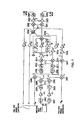
- FIG. 7 is a schematic of the wheel motor control during balancing and normal locomotion, in accordance with an embodiment of the present invention.
- FIG. 8 shows an illustrative diagram of an idealized balancing transporter with a rigid wheel in motion at a constant velocity across a flat surface
- FIG. 9 illustrates the relationship among various speed limiting parameters for a typical balancing transporter
- FIG. 10 is a circuit diagram of a battery in series with a load in accordance with an embodiment of the present invention.
- FIG. 11 is a flow diagram illustrating a method for estimating battery parameters
- FIG. 12 is a flow diagram illustrating a method for limiting the speed of a balancing transporter.
- FIGS. 13A-B illustrate setting a speed limit for a transporter.
- An alternative to operation of a statically stable transporter is that dynamic stability may be maintained by action of the user, as in the case of a bicycle or motorcycle or scooter, or, in accordance with embodiments of the present invention, by a control loop, as in the case of the human transporter described in U.S. Pat. No. 5,701,965.
- the invention may be implemented in a wide range of embodiments. A characteristic of many of these embodiments is the use of a pair of laterally disposed ground-contacting members to suspend the subject over the surface with respect to which the subject is being transported.
- the ground or other surface, such as a floor, over which a transporter in accordance with the invention is employed may be referred to generally herein as the “ground.”
- the ground-contacting members are typically motor-driven.
- the configuration in which the subject is suspended during locomotion lacks inherent stability at least a portion of the time with respect to a vertical in the fore-aft plane but is relatively stable with respect to a vertical in the lateral plane.
- Stability means that in response to a perturbation a stable device will tend towards its unperturbed state.
- primary wheels refers to a minimum set of a transporter's wheels on which the transporter is capable of operating stably. More generally, the term “primary ground-contacting members” allows for a more general class of members that includes but is not limited to wheels. Hence, as used in this description and in any appended claims, “primary ground-contacting members” refers to a minimum set of a transporter's ground-contacting members on which the transporter is capable of operating stably. Other ground-contacting members may include, without limitation: arcuate sections of a wheel, clusters of wheels, treads, etc.
- fore-aft stability may be achieved by providing a control loop, in which one or more motors are included, for operation of a motorized drive in connection with the ground-contacting members.
- a pair of ground-contacting members may, for example, be a pair of wheels or a pair of wheel clusters.
- each cluster may include a plurality of wheels.
- Each ground-contacting member may instead be a plurality (typically a pair) of axially-adjacent, radially supported and rotatably mounted arcuate elements.
- the ground-contacting members are driven by the motorized drive in the control loop in such a way as to maintain, when the transporter is not in locomotion, the center of mass of the transporter above the region of contact of the ground-contacting members with the ground, regardless of disturbances and forces operative on the transporter.
- a ground-contacting member typically has a “point” (actually, a region) of contact or tangency with the surface over which the transporter is traveling or standing. Due to the compliance of the ground-contacting member, the “point” of contact is actually an area, where the region of contact may also be referred to as a contact patch.
- the weight of the transporter is distributed over the contact region, giving rise to a distribution of pressures over the region, with the center of pressure displaced forward during forward motion.
- the distribution of pressures is a function both of the composition and structure of the wheel, the rotational velocity of the wheel, the torque applied to the wheel, and thus of the frictional forces acting on the wheel.
- a force in the direction of motion is required to overcome rolling friction (and other frictional forces, including air resistance).
- Gravity may be used, in accordance with preferred embodiments of the invention, to provide a torque about the point of contact with the surface in a direction having a component in the sense of desired motion.
- FIG. 8 to illustrate these principles, a diagram is shown of the forces acting on a transporter that locomotes with constant velocity v on a single wheel over a flat surface.
- the principles now discussed may readily be generalized to operation on a sloped surface and to accommodate any other external forces that might be present.
- Wheel 160 of radius R w rotates with respect to chassis 162 about axle 164 and contacts the underlying surface at point P. For purposes of illustration only, it is assumed that wheel 160 contacts the surface at a point.
- the line 170 from the CG to point P is at an angle ⁇ s relative to the vertical 172 .
- FIG. 1 shows a simplified embodiment of the invention.
- a personal transporter is shown and designated generally by numeral 18 .
- a subject 10 stands on a support platform 12 and holds a grip 14 on a handle 16 attached to the platform 12 , so that the transporter 18 of this embodiment may be operated in a manner analogous to a scooter.
- a control loop may be provided so that leaning of the subject results in the application of torque to wheel 20 about axle 22 thereby causing an acceleration of the transporter.
- Transporter 18 is statically unstable, and, absent operation of the control loop to maintain dynamic stability, subject 10 will no longer be supported in a standing position and will fall from platform 12 .
- Different numbers of wheels or other ground-contacting members may advantageously be used in various embodiments of the invention as particularly suited to varying applications.
- the number of ground-contacting members may be any number equal to, or greater than, one.
- the dimensions of platform 12 and indeed of the entire ground-contacting module, designated generally by numeral 6 , are advantageously comparable to the dimensions of the footprint or shoulder width of user 10 .
- transporter 18 may advantageously be used as a mobile work platform or a recreational transporter such as a golf cart, or as a delivery transporter.
- Transporter 18 may be operated in a station-keeping mode, wherein balance is maintained substantially at a specified position. Additionally, transporter 18 , which may be referred to herein, without limitation, as a “transporter,” may also maintain a fixed position and orientation when the user 10 is not on platform 12 . This mode of operation, referred to as a “kickstand” mode, prevents runaway of the transporter and provides for the safety of the user and other persons. A force plate 8 or other sensor, disposed on platform 12 , detects the presence of a user on the transporter.
- FIG. 2 Another embodiment of a balancing transporter in accordance with the present invention is shown in FIG. 2 and designated generally by numeral 24 .
- Personal transporter 24 shares the characteristics of transporter 18 of FIG. 1 , namely a support platform 12 for supporting subject 10 and grip 14 on handle 16 attached to platform 12 , so that the transporter 18 of this embodiment may also be operated in a manner analogous to a scooter.
- FIG. 2 shows that while transporter 24 may have clusters 26 each cluster having a plurality of wheels 28 , transporter 24 remains statically unstable and, absent operation of a control loop to maintain dynamic stability, subject 10 will no longer be supported in a standing position and will fall from platform 12 .
- FIG. 2 as in the embodiment of FIG.
- the primary ground-contacting members are a pair of wheels.
- Supplemental ground-contacting members may be used in stair climbing and descending or in traversing other obstacles. In one mode of operation, for example, it is possible to rotate clusters 26 so that two wheels on each of the clusters are simultaneously in contact with the ground. Stair climbing and flat-terrain locomotion may both be achieved, however, with the transporter supported on only a single set of primary ground-contacting members.
- Gravity defines the vertical axis z, while the axis coincident with the wheel axis 22 may be used to define a lateral axis y, and a fore-aft axis x is defined by the forward direction of motion of the transporter.
- the plane defined by the vertical axis z and the lateral axis y will sometimes be referred to as the “lateral plane”, and the plane defined by the fore-aft axis x and the vertical axis z will sometimes be referred to as the “fore-aft plane”.
- Directions parallel to the axes x and y are called the fore-aft and lateral directions respectively. It can be seen that the transporter, when relying on the pair of wheels 20 for contacting the ground, is inherently unstable with respect to a vertical in the fore-aft direction, but is relatively stable with respect to a vertical in the lateral direction. In other embodiments of the invention described below, the transporter may also be unstable with respect to yaw about the z axis.
- the axes may also be defined with respect to platform 12 in cases such as where the ground-contacting member is a uniball.
- FIG. 3 A simplified control algorithm for achieving balance in the embodiment of the invention according to FIG. 1 when the wheels are active for locomotion is shown in the block diagram of FIG. 3 .
- the plant 61 is equivalent to the equations of motion of a system with a ground contacting module driven by a single motor, before the control loop is applied. T identifies the wheel torque. The remaining portion of the figure is the control used to achieve balance.
- the boxes 62 and 63 indicate differentiation.
- pitch offset may be adjusted by the user, for example, by means of a thumb wheel 32 , shown in FIG. 1 .
- An adjustable pitch offset is useful under a variety of circumstances. For example, when operating the transporter on an incline, it may be desirable for the operator to stand erect with respect to gravity when the transporter is stationary or moving at a uniform rate. On an upward incline, a forward torque on the wheels is required in order to keep the wheels in place.
- ⁇ 0 may advantageously be manually offset to allow control with respect to a stationary pitch comfortable to the user.
- K 3 The size of K 3 will determine the extent to which the transporter will seek to return to a given location. With a non-zero K 3 , the effect of x 0 is to produce a specified offset ⁇ x 0 from the fiducial reference by which x is measured. When K 3 is zero, the transporter has no bias to return to a given location. The consequence of this is that if the transporter is caused to lean in a forward direction, the transporter will move in a forward direction, thereby maintaining balance. Such a configuration is discussed further below.
- lean is often used with respect to a system balanced on a single point of a perfectly rigid member.
- the point (or line) of contact between the member and the underlying surface has zero theoretical width.
- lean may refer to a quantity that expresses the orientation with respect to the vertical (i.e., an imaginary line passing through the center of the earth) of a line from the center of gravity (CG) of the system through the theoretical line of ground contact of the wheel.
- CG center of gravity
- system refers to all mass caused to move due to motion of the ground-contacting elements with respect to the surface over which the transporter is moving.
- both the left wheel motion and the right wheel motion permits adjustments to be made to prevent unwanted turning of the transporter and to account for performance variations between the two drive motors.
- a user control input such as a joystick may be used to adjust the torques of each motor.
- the joystick has axes indicated in FIG. 4 .
- forward motion of the joystick is used to cause forward motion of the transporter, and reverse motion of the joystick causes backward motion of the transporter.
- a left turn similarly is accomplished by leftward motion of the joystick.
- the joystick is moved to the right.
- the configuration used here permits the transporter to turn in place when the joystick is moved to the left or to the right, by causing rotation of left and right motors, and hence left and right wheels, at equal rates in opposite senses of rotation.
- a control system 51 is used to control the motor drives and actuators of the embodiment of FIGS. 1-3 to achieve locomotion and balance. These include motor drives 531 and 532 for left and right wheels respectively. If clusters are present as in the embodiment of FIG. 2 , actuators 541 and 542 for left and right clusters respectively.
- the control system has data inputs including user interface 561 , pitch sensor 562 for sensing fore-aft pitch, and wheel rotation sensors 563 , and pitch rate sensor 564 . Pitch rate and pitch may be derived through the use of gyroscopes or inclinometers, for example, alone or in combination.
- Control system 51 also may contain a balancing margin monitor which combines information on current battery parameters with information on motor parameters to calculate a maximum current speed of the transporter.
- the control system 51 may limit the speed of the transporter to ensure that adequate speed reserve is available to maintain balance.
- the control system 51 may further contain logic to reduce the speed of the transporter to avoid damaging the battery due to generation of over voltage. This condition can occur if the transporter is provided with capability to regenerate the battery during braking and when travelling downhill.
- a grip 14 may be conveniently provided with a thumb wheel 32 (shown in FIG. 1 ) or thumb-operated joystick for directional control, although other methods of control may also be used.
- Thumb wheel 32 may serve multiple control purposes as will now be described.
- handle 16 and grip 14 may be absent altogether, and the platform 12 may be equipped with sensors, such as force plate 8 , for example, to detect leaning of the subject.
- the pitch of the transporter is sensed and may be used to govern operation of the control loop, so that if the subject leans forward, the transporter will move forward to maintain a desired velocity or to provide desired acceleration. Accordingly, a forward lean of the subject will cause the transporter to pitch forward and produce forward movement; a backward lean will cause the transporter to pitch backward and produce backward movement.
- Appropriate force transducers may be provided to sense leftward and rightward leaning and related controls provided to cause left and right turning as a result of the sensed leaning.
- Leaning may also be detected using proximity sensors. Additionally, operation of the transporter may be governed on the basis of the orientation of the user with respect to the platform.
- the transporter may be equipped with a foot- (or force-) actuated switch sensitive to the presence of a user on the transporter.
- the transporter may be powered automatically upon ascent of a user onto the platform.
- the transporter may be programmed to enter a dynamic “kickstand” mode in which the transporter remains balanced in place when the user alights.
- the transporter is ready for the user to resume travel by reboarding the transporter.
- the transporter is thus safely parked while not actively operated by a user aboard the transporter.
- FIG. 6 is a block diagram providing detail of a driver interface assembly 273 .
- a peripheral microcomputer board 291 receives an input from joystick 292 as well as from inclinometer 293 or another tilt-determining arrangement.
- the inclinometer provides information signals as to pitch and pitch rate.
- inclinometer means any device providing an output indicative of pitch or pitch rate, regardless of the arrangement used to achieve the output; if only one of the pitch and pitch rate variables is provided as an output, the other variable can be obtained by suitable differentiation or integration with respect to time.
- a second inclinometer to provide information as to roll and roll rate or, alternatively, the resultant of system weight and centrifugal force.
- Other inputs 294 may also be desirably provided as an input to the peripheral micro controller board 291 . Such other inputs may include signals gated by switches (knobs and buttons) for platform adjustment and for determining the mode of operation.
- the peripheral micro controller board 291 also has inputs for receiving signals from the battery stack 271 as to battery voltage, battery current, and battery temperature.
- the peripheral micro controller board 291 is in communication over bus 279 with a central micro controller board that may be used to control the wheel motors as described below in connection with FIG. 7 .
- FIG. 7 is a block diagram showing control algorithms, suitable for use in conjunction with the control assemblies of FIG. 6 to provide stability for a transporter according to the embodiment of FIGS. 1-2 and other embodiments in which the transporter and payload are balanced on two ground-contacting members, both during locomotion and in a fixed position.
- the following conventions are used in connection with the description below:
- FIG. 7 shows the control arrangement for the motors of the right and left wheels.
- the arrangement has inputs of ⁇ , ⁇ dot over ( ⁇ ) ⁇ , r ⁇ dot over ( ⁇ ) ⁇ wl (linear velocity of the left wheel relative to the world coordinate system) and r ⁇ dot over ( ⁇ ) ⁇ wr (linear velocity of the right wheel), in addition to directional inputs 3300 determined by joystick position along X and Y axes of a reference coordinate system.
- Inputs ⁇ , ⁇ dot over ( ⁇ ) ⁇ , and error signals x and ⁇ dot over (x) ⁇ (described below), subject to gains K 1 , K 2 , K 3 , and K 4 respectively, become inputs to summer 3319 , which produces the basic balancing torque command for the wheels, in the general manner described above in connection with FIG. 3 above.
- the output of summer 3319 is combined with the output of yaw PID loop 3316 (described below) in summer 3320 , then divided in divider 3322 and limited in saturation limiter 3324 , to produce the left wheel torque command.
- the output of summer 3319 is combined with the output of PID loop 3316 in summer 3321 , then divided in divider 3323 and limited in saturation limiter 3325 , to produce the right wheel torque command.
- a directional input along the X axis moves the reference coordinate system along its X axis relative to the world coordinate system (which represents the traveled surface), at a velocity proportional to the displacement of the joystick.
- a directional input along the Y axis rotates the reference coordinate system about its Z axis at an angular velocity proportional to the displacement of the joystick.
- motion of the joystick in the positive X direction is here interpreted to mean forward motion; motion of the joystick in the negative X direction means reverse motion.
- motion of the joystick in the positive Y direction means leftward turning, counter-clockwise as viewed from above; motion of the joystick in the negative Y direction means rightward turning clockwise as viewed from above.
- the directional inputs Y and X are given deadband via deadband blocks 3301 and 3302 respectively, to widen the neutral position of the joystick, then subject to gains K 11 and K 10 , then rate-limited by limiters 3303 and 3304 respectively, which limit the angular and linear accelerations respectively of the reference coordinate system.
- the sum of these outputs achieved through summer 3305 becomes the reference velocity ⁇ dot over (x) ⁇ r ref whereas the difference of these outputs achieved through summer 3306 becomes the reference velocity ⁇ dot over (x) ⁇ l ref .
- Displacement error signal x is derived by integrating r ⁇ dot over ( ⁇ ) ⁇ wl and r ⁇ dot over ( ⁇ ) ⁇ wr in integrators 3310 and 3309 , limiting the results in saturation limiters 3312 and 3311 , and then averaging their outputs via summer 3313 and divider 3315 . The difference between these displacements, determined via summer 3314 , produces the yaw error signal ⁇ .
- the yaw error signal ⁇ is run through a standard proportional-plus-integral-plus-derivative (PID) control loop 3316 , the output of which is combined with the output of the basic balancing torque command of summer 3319 , to produce the individual wheel torque commands, which cause the wheels to maintain fore-aft stability and also cause the transporter to align itself with the axes of, and follow the origin of, the reference coordinate system as directed by directional input 3300 .
- PID proportional-plus-integral-plus-derivative
- the directional input 3300 (which may be a joystick) which will provide a positive x for forward motion.
- the signal is divided and summed in summers 3308 and 3307 , and subtracted from the right and left wheel velocity ⁇ dot over (x) ⁇ R and ⁇ dot over (x) ⁇ L providing a negative correction; this correction leads ultimately to a negative torque contribution at summer 3319 , causing the wheels to move backward, so as to create a torque due to gravity that causes the transporter to lean forward.
- This forward lean leads to changing ⁇ and ⁇ dot over ( ⁇ ) ⁇ , which leads to positive corrections in summer 3319 , causing the transporter to move forward.
- Acceleration of the transporter may be established by system lean.
- system lean For example, to achieve forward acceleration of the transporter by forward system lean; the center of gravity of the system (transporter and payload) would be placed forward of the center of the pressure distribution of the contact region where the wheels contact the ground—the more the lean, the more the acceleration.
- leaning in conjunction with gravity and friction, determines acceleration (positive or negative) of the system. In this manner, if the transporter is moving forward, pitching the system back will achieve braking. Because the transporter must overcome friction, there is typically some system lean when the transporter is moving at constant velocity over level ground. In other words, looking at the torque on the transporter caused by gravity and the torque caused by all other external forces, the torque applied by the motorized drive is adjusted so that the net torque from all these sources produces a desired acceleration.
- any of the foregoing embodiments of a transporter in accordance with the present invention may be provided with speed limiting to maintain balance and control, which may otherwise be lost if the wheels (arcuate elements, or other ground-contacting members) were permitted to reach a maximum operating speed for the transporter.
- maximum operating speed as used in the specification and in any appended claims, unless context requires otherwise, will mean the maximum speed at which the transporter is presently capable of being propelled. This maximum operating speed will typically be a function of an instantaneous capability of the transporter, such as the capability of the drive system and/or the capability of the energy storage device provided to power drive system.
- the energy storage device may be chemical (in which case it is referred to as a ‘battery’) or otherwise.
- the “instantaneous capability” of the energy storage device is a measure of the instantaneous power that can be delivered by the device and the “maximum capability” of the device is a measure of the greatest power that the device can supply at any time.
- the terms “speed intervention band,” “intervention speed,” and “speed limit” as used in the specification and in any appended claims, unless context requires otherwise, will mean a range or band of speeds extending from an “intervention speed” at the lower end to a “speed limit” at the upper end.
- the intervention speed is a threshold speed at which means may be employed to reduce the transporter's speed.
- a transporter will typically be operated with a margin between the maximum operating speed and the speed limit, as illustrated in FIG. 9 . This margin helps ensure that the transporter will maintain balance over a range of operating conditions.
- Speed reduction may be accomplished by pitching the transporter back in the direction opposite from the current direction of travel, which causes the transporter to slow down. (As discussed above, the extent and direction of system lean determine the transporter's acceleration.)
- the transporter is pitched back by adding a pitch modification to the inclinometer pitch value.
- Speed reduction can occur whenever the transporter velocity of the transporter exceeds the intervention speed.
- the pitch modification is determined by looking at the difference between the transporter velocity and the intervention speed, integrated over time.
- the automatic pitch modification sequence may be maintained until the transporter slows to the desired dropout speed (some speed below the intervention speed), and the pitch angle may then be smoothly returned to its original value.
- One method for determining the maximum operating speed of the transporter if the energy storage device is a battery, is to monitor the battery voltage and current produced, which are then used to estimate the maximum velocity the transporter is currently capable of maintaining. Another method is to measure the voltages of the battery and the motor and to monitor the difference between the two; the difference provides an estimate of the amount of velocity margin (or balancing margin) currently available to the transporter.
- a method for estimating the instantaneous capability of a battery is provided.
- a simplified model 5000 is used for the battery, consisting of a “perfect” DC voltage source 5010 with “open circuit” voltage, V oc , a series resistance for the battery, R bat , a current, I bat , and a battery voltage, V bat .
- V oc and R bat cannot be measured but can be estimated from measurements of V bat and I bat .
- these variables should follow a linear relationship:
- V bat V oc ⁇ ( I bat *R bat ) (Eqn. 5).
- V oc and R bat For example, a regression analysis using a least squares technique may be employed to derive estimated values of V oc and R bat from the measured values of V bat and I bat .
- V oc and R bat will change, such as, for example, due to ambient temperature, battery temperature, battery age, battery usage (both the overall amount of usage and usage pattern), and over time as the battery charge is depleted (and regenerated). Accordingly, a more accurate estimate may be obtained if the more recent measured values of V bat and I bat are used for the regression or more recent values are weighted more heavily than older values.
- a recursive least squares technique with exponential forgetting is employed to estimate V oc and R bat for the battery.
- step 5200 newly measured values of V bat and I bat are used to correct the estimated values using a low pass filtering algorithm.
- the variables are initialized (step 5210 ), with V oc and R bat set to typical values.
- V bat and I bat are measured periodically (step 5220 ).
- This calculation identifies data points that may provide additional information from which to refine the estimate of current battery parameters. For example, when the transporter is at rest, little current is drawn and a series of such measurements could skew the estimated value for the battery parameters from their true values, as filtering progresses. An appropriately set threshold for D can be used to mitigate the impact of such data points on the estimate.
- V oc is initialized to the first measured value of V bat .
- R bat is set to a value higher than expected in typical operation. This approach to initializing R bat allows the algorithm to bring the R bat estimate down during operation.
- Matrix element p b in Eqn. 7 may be set to zero, in this embodiment.
- estimated values of battery parameters are used to calculate a maximum operating speed for a transporter based on the state of the battery and other transporter parameters, such as motor current.
- the values for M and B may vary over time and either M or B may be functions of current values of transporter operating parameters such as battery open circuit voltage and internal resistance and motor parameters, such as backEMF gain and motor resistance.
- an estimated maximum operating speed for a transporter is calculated as a linear function of the battery open circuit voltage, the battery internal resistance and a filtered average motor current, where the value of the average motor current is filtered with a low pass filter.
- dual redundant brushless DC motors are provided to drive each wheel of a transporter, which has wheels disposed as in FIG. 1 .
- Dual batteries are provided with each battery powering two motors.
- the motors may be paired so that the two motors driving a wheel are powered by different batteries, providing redundancy.
- the lesser of the estimated values of V oc for the two batteries and the greater of the estimated values of at for the two batteries may be employed in Eqn. 14, and transporter speed limited accordingly. As the batteries are discharged, the maximum operating speed for the transporter will decrease.
- values for K ell , the backEMF gain of each motor, and R ll , the measured resistance between the two phases of the DC motor may be estimated by using measured values of transporter operating parameters such as motor temperature. Eqn. 14 may then be periodically modified accordingly.
- the maximum operating speed can then be used to set an intervention speed and a speed limit for the transporter, ensuring that adequate balancing margin is maintained over varying terrain and operating conditions.
- the balancing margin can be empirically determined to produce the desired performance characteristics of the transporter.
- Speed limit can then set by subtracting the balancing margin from the maximum operating speed.
- the speed limit may be set as a function of the filtered average motor current, I mot , for the transporter or as a function of maximum operating speed for a given I mot .
- the speed limit may be a fixed offset from the maximum operating speed for the full range of I mot (as depicted in FIG. 13A ) or may vary as I mot varies.
- the speed limit can be set to an arbitrary value for a specific range of I mot (as depicted in FIG. 13 B).
- ⁇ a pitch modification
- ⁇ a speed intervention band
- the upper end of the band, the speed limit may be set by subtracting a balancing margin from the maximum operating speed for the transporter.
- the intervention speed may be set by subtracting the extent of the speed intervention band from the speed limit.
- Each of the balancing margin and the extent of the speed intervention band may be constants or may be determined adaptively.
- separate speed limits and intervention bands may be defined for motion of the transporter's center of mass in the forward and in the aft directions.
- the maximum operating speed may be estimated by a variety of methods, including the method described above. Note that the maximum operating speed for the transporter may decrease as the transporter's battery or other fuel source is depleted and the intervention speed and the speed limit may be adjusted accordingly.
- the relationship among various speed limiting parameters for a typical balancing transporter is illustrated in FIG. 9 .
- the speed of the transporter is then monitored 6220 .
- the transporter may be slowed by increasing 6240 the pitch modification, ⁇ . Inspection of Eqn. 15 shows that the transporter will respond to the modification by increasing motor torque, causing the system to accelerate. If, for example, the system is moving in the forward direction, the acceleration will cause the system to pitch backwards. The system will respond to this decrease in system pitch value by then reducing motor torque, decelerating the system.
- ⁇ may be determined 6230 by looking at the difference between the transporter speed and the intervention speed, integrated over time.
- the pitch modification sequence is repeated 6250 until the transporter slows to a desired dropout speed, which may be the intervention speed, and then the pitch modification may be smoothly returned 6260 to zero.
- This embodiment may be used advantageously to maintain a speed margin for balancing the transporter in the fore-aft plane and to govern the speed of the transporter.
- the pitch modification may be calculated as follows.
- A ( S int ⁇ S act ); (proportional term) (Eqn. 16)
- ⁇ C+A*G p +B*G d , (Eqn. 19)
- this modification may be introduced to Eqn. 15 smoothly and incrementally. Note that the integral term contribution to the pitch modification is zero until the speed of the transporter exceeds the speed limit. At that point, the term can add substantially to the value of the pitch modification. Thus, the speed limiting effect on the system can become pronounced as the speed limit is exceeded.
- Calculation of the pitch modification may be repeated periodically until transporter speed decreases below a drop-out value, which may be the intervention speed.
- the pitch modification calculation and changes to the pitch modification may be repeated periodically.
- the pitch modification may be smoothly and incrementally decreased until the modification returns to zero.
- a transporter is provided with means to regenerate batteries supplying power to the drive arrangement.
- Such regeneration can occur, for example, during hard braking or when the transporter is going downhill.
- damage may occur if the battery is at full capability and the battery regeneration circuitry forces additional energy into the battery.
- Such energy is dissipated as heat and the battery voltage may surge. Both effects can cause damage to the battery and drive electronics.
- the transporter's speed limit may be modified to prevent an over voltage condition during battery regeneration.
- the battery voltage is monitored periodically and filtered with a low pass filter. If the filtered battery voltage exceeds an over voltage threshold, the speed limit for the transporter, or equivalently the intervention speed, may be reduced.
- an over voltage range is set for the transporter, beginning at the over voltage threshold.
- the speed limit for the transporter is reduced linearly over this range as a function of battery voltage to a minimum speed characteristic of the transporter.
- the minimum speed limit may be set equal to the range of the intervention band.
- logic blocks e.g., programs, modules, functions, or subroutines
- logic elements may be added, modified, omitted, performed in a different order, or implemented using different logic constructs (e.g., logic gates, looping primitives, conditional logic, and other logic constructs) without changing the overall results or otherwise departing from the true scope of the invention.
- the present invention may be embodied in many different forms, including, but in no way limited to, computer program logic for use with a processor (e.g., a microprocessor, microcontroller, digital signal processor, or general purpose computer), programmable logic for use with a programmable logic device (e.g., a Field Programmable Gate Array (FPGA) or other PLD), discrete components, integrated circuitry (e.g., an Application Specific Integrated Circuit (ASIC)), or any other means including any combination thereof.
- a processor e.g., a microprocessor, microcontroller, digital signal processor, or general purpose computer
- programmable logic for use with a programmable logic device
- FPGA Field Programmable Gate Array
- ASIC Application Specific Integrated Circuit
- Source code may include a series of computer program instructions implemented in any of various programming languages (e.g., an object code, an assembly language, or a high-level language such as Fortran, C, C++, JAVA, or HTML) for use with various operating systems or operating environments.
- the source code may define and use various data structures and communication messages.
- the source code may be in a computer executable form (e.g., via an interpreter), or the source code may be converted (e.g., via a translator, assembler, or compiler) into a computer executable form.
- the computer program may be fixed in any form (e.g., source code form, computer executable form, or an intermediate form) either permanently or transitorily in a tangible storage medium, such as a semiconductor memory device (e.g., a RAM, ROM, PROM, EEPROM, or Flash-Programmable RAM), a magnetic memory device (e.g., a diskette or fixed disk), an optical memory device (e.g., a CD-ROM), a PC card (e.g., PCMCIA card), or other memory device.
- the computer program may be fixed in any form in a signal that is transmittable to a computer using any of various communication technologies, including, but in no way limited to, analog technologies, digital technologies, optical technologies, wireless technologies, networking technologies, and internetworking technologies.
- the computer program may be distributed in any form as a removable storage medium with accompanying printed or electronic documentation (e.g., shrink wrapped software or a magnetic tape), preloaded with a computer system (e.g., on system ROM or fixed disk), or distributed from a server or electronic bulletin board over the communication system (e.g., the Internet or World Wide Web.)
- printed or electronic documentation e.g., shrink wrapped software or a magnetic tape
- a computer system e.g., on system ROM or fixed disk
- a server or electronic bulletin board over the communication system (e.g., the Internet or World Wide Web.)
- Hardware logic including programmable logic for use with a programmable logic device
- implementing all or part of the functionality previously described herein may be designed using traditional manual methods, or may be designed, captured, simulated, or documented electronically using various tools, such as Computer Aided Design (CAD), a hardware description language (e.g., VHDL or AHDL), or a PLD programming language (e.g., PALASM, ABEL, or CUPL.)
- CAD Computer Aided Design
- a hardware description language e.g., VHDL or AHDL
- PLD programming language e.g., PALASM, ABEL, or CUPL.
Abstract
Description
F b cos θs =f b, (Eqn. 1)
-
- where fb is the component of the reaction force acting transverse to
axis 174 between the CG and point P. In order to prevent the transporter from falling, a stability condition must also exist, namely that no net force acts on the CG in a direction transverse toline 170, i.e., there is no net torque about the point of contact P during motion at constant velocity (i.e., in an inertial frame of reference where the point P is fixed). This condition may be expressed as:
F g sin θs =f b, (Eqn. 2) - where Fg sin θs is the “tipping” component of gravity, and fb is the counter-tipping component of the reactive force on the transporter caused by wheel rotation (fb=Fb cos θ), and where θ is the angle shown
line 170 andline 174.
- where fb is the component of the reaction force acting transverse to
θs=(μ/F g)v, (Eqn. 3)
-
- showing that increasing velocity requires increased lean to overcome the effects of friction. Additionally, a control loop that imposes stability on the system will respond to an increased lean by increasing velocity of the system. While the preceding discussion assumed constant velocity, additional lean beyond that required to overcome the effects of friction will result in acceleration since an additional forward-directed force acts on the CG. Conversely, in order to achieve acceleration (or deceleration) of the transporter, additional leaning (forward or backward) must be provided in a manner discussed in further detail below.
T=K 1(θ−θ0)+K 2({dot over (θ)}−{dot over (θ)}0)+K 3(x−x 0)+K 4({dot over (x)}−{dot over (x)}0), (Eqn. 4)
-
- where:
- T denotes a torque applied to a ground-contacting element about its axis of rotation;
- θ is a quantity corresponding to the lean of the entire system about the ground contact, with θ0 representing the magnitude of a system pitch offset, all as discussed in detail below;
- x identifies the fore-aft displacement along the surface relative to a fiducial reference point, with x0 representing the magnitude of a specified fiducial reference offset;
- a dot over a character denotes a variable differentiated with respect to time; and
- a subscripted variable denotes a specified offset that may be input into the system as described below; and
- K1, K2, K3, and K4 are gain coefficients that may be configured, either in design of the system or in real-time, on the basis of a current operating mode and operating conditions as well as preferences of a user. The gain coefficients may be of a positive, negative, or zero magnitude, affecting thereby the mode of operation of the transporter, as discussed below. The gains K1, K2, K3, and K4 are dependent upon the physical parameters of the system and other effects such as gravity. The simplified control algorithm of
FIG. 3 maintains balance and also proximity to the reference point on the surface in the presence of disturbances such as changes to the system's center of mass with respect to the reference point on the surface due to body motion of the subject or contact with other persons or objects. It should be noted that the amplifier control may be configured to control motor current (in which case torque T is commanded, as shown inFIG. 3 ) or, alternatively, the voltage applied to the motor may be controlled, in which case the commanded parameter is velocity.
-
- 1. Variables defined in world coordinates are named using a single subscript in capital letters. World coordinates are coordinates fixed to the earth (inertial).
- 2. A non-subscripted r identifies a wheel radius.
- 3. Lower case subscripts are used to indicate other attributes, e.g., right/left, etc.: r=right; l=left; ref=reference; f=finish; s=start.
- 4. All angles are positive in the clockwise direction, where positive travel is in the positive x direction.
- 5. A dot over a variable indicates differentiation in time, e.g., {dot over (θ)}.
D=(V prev −V bat)2+(I prev −I bat)2 (Eqn. 6).
This calculation identifies data points that may provide additional information from which to refine the estimate of current battery parameters. For example, when the transporter is at rest, little current is drawn and a series of such measurements could skew the estimated value for the battery parameters from their true values, as filtering progresses. An appropriately set threshold for D can be used to mitigate the impact of such data points on the estimate.
- (1) calculate update gains Kvoc and Krbat (step 5240):
- where,pa is the direct Voc covariance matrix element,
- pb is the cross coupling covariance matrix element, and
- pc is the direct Rbat covariance matrix element,
- (Note: pa, pb, and pc represent the uncertainty in the state estimate);
- where,pa is the direct Voc covariance matrix element,
- (2) calculate error between battery state estimate and the new data point (step 5250):
Err=V bat−(V oc −I bat *R bat) (Eqn. 8); - (3) update battery state estimate (step 5270):
- (If D is less than the threshold (step 5265), Krbat may be set to zero (step 5265) so that Rbat is not updated.)
V oc =V oc +K voc *Err (Eqn. 9)
R bat =R bat +K rbat *Err (Eqn. 10); and
- (If D is less than the threshold (step 5265), Krbat may be set to zero (step 5265) so that Rbat is not updated.)
- (4) update signal content variables (step 5280), if D is greater than the threshold (step 5275):
Vprev=Vbat (Eqn. 11)
Iprev=Ibat (Eqn. 12).
The process can continue with repeated measurement of Vbat and Ibat (step 5220).
Y=M*I mot +B. (Eqn. 13)
The values for M and B may vary over time and either M or B may be functions of current values of transporter operating parameters such as battery open circuit voltage and internal resistance and motor parameters, such as backEMF gain and motor resistance.
Y=−((√{square root over (3)}÷K ell)*(R bat+(R ll÷2))*I mot)+(V oc +K ell) (Eqn. 14)
where, Kell is the line-to-line backEMF constant of each motor;
-
- Rll is the measured resistance between the two phases of the DC motor;
- Imot is an average motor current, where Imot is calculated by summing the filtered currents for the two motors for each wheel and then taking the greater of the absolute values of these sums;
- Voc is the estimated open circuit voltage of a battery; and
- Rbat is the estimated internal resistance of a battery.
T=K 1(θ−(Δ+θ0))+K 2 {dot over (θ)}+K 3(x+x 0)+K 4 {dot over (x)} (Eqn. 15)
Adding the pitch modification, Δ, allows the
A=(S int −S act); (proportional term) (Eqn. 16)
B=S′ act *A, if (S′act>0 and A<0), otherwise B=0; (derivative term) (Eqn. 17)
C=C prev+(D*(S sl −S act)) if Cprev<=0,. otherwise, C=0 (integral term) (Eqn. 18)
And set Δ=C+A*G p +B*G d, (Eqn. 19)
-
- where:
- Sact is the instantaneous velocity of the transporter's center of mass,
- Sint is the intervention speed;
- Ssl is the speed limit;
- S′act is the acceleration of the transporter;
- Cprev is the value of C from the previous calculation of the integral term (initialized to zero);
- D is a gain term;
- Gp is a gain term for the contribution to the desired pitch modification that is proportional to transporter speed.
- Gd is a gain term for the contribution to the desired pitch modification that is proportional to transporter acceleration.
Δ=C prev+(D*(S sl −S act)) if C<0 and otherwise 0; and (Eqn. 20).
C=Δ (Eqn. 21).
Claims (28)
Priority Applications (2)
| Application Number | Priority Date | Filing Date | Title |
|---|---|---|---|
| US10/460,970 US6874591B2 (en) | 1994-05-27 | 2003-06-13 | Speed limiting for a balancing transporter |
| US10/669,879 US6868931B2 (en) | 1994-05-27 | 2003-09-23 | Speed limiting for a balancing transporter accounting for variations in system capability |
Applications Claiming Priority (7)
| Application Number | Priority Date | Filing Date | Title |
|---|---|---|---|
| US08/250,693 US5701965A (en) | 1993-02-24 | 1994-05-27 | Human transporter |
| US08/384,705 US5971091A (en) | 1993-02-24 | 1995-02-03 | Transportation vehicles and methods |
| US08/479,901 US5975225A (en) | 1993-02-24 | 1995-06-07 | Transportation vehicles with stability enhancement using CG modification |
| US09/325,976 US7370713B1 (en) | 1993-02-24 | 1999-06-04 | Personal mobility vehicles and methods |
| US38884502P | 2002-06-14 | 2002-06-14 | |
| US38913402P | 2002-06-14 | 2002-06-14 | |
| US10/460,970 US6874591B2 (en) | 1994-05-27 | 2003-06-13 | Speed limiting for a balancing transporter |
Related Parent Applications (1)
| Application Number | Title | Priority Date | Filing Date |
|---|---|---|---|
| US09/325,976 Continuation-In-Part US7370713B1 (en) | 1993-02-24 | 1999-06-04 | Personal mobility vehicles and methods |
Related Child Applications (2)
| Application Number | Title | Priority Date | Filing Date |
|---|---|---|---|
| US08/384,705 Continuation-In-Part US5971091A (en) | 1993-02-24 | 1995-02-03 | Transportation vehicles and methods |
| US10/669,879 Continuation-In-Part US6868931B2 (en) | 1994-05-27 | 2003-09-23 | Speed limiting for a balancing transporter accounting for variations in system capability |
Publications (2)
| Publication Number | Publication Date |
|---|---|
| US20030231022A1 US20030231022A1 (en) | 2003-12-18 |
| US6874591B2 true US6874591B2 (en) | 2005-04-05 |
Family
ID=32601243
Family Applications (1)
| Application Number | Title | Priority Date | Filing Date |
|---|---|---|---|
| US10/460,970 Expired - Lifetime US6874591B2 (en) | 1994-05-27 | 2003-06-13 | Speed limiting for a balancing transporter |
Country Status (1)
| Country | Link |
|---|---|
| US (1) | US6874591B2 (en) |
Cited By (64)
| Publication number | Priority date | Publication date | Assignee | Title |
|---|---|---|---|---|
| US20050121238A1 (en) * | 2003-11-04 | 2005-06-09 | Shinji Ishii | Traveling apparatus and method for controlling thereof |
| US20060049783A1 (en) * | 2004-09-08 | 2006-03-09 | Daifuku Co., Ltd. | Article transport vehicle |
| US20070050111A1 (en) * | 2005-08-31 | 2007-03-01 | Invacare Corp. | Method and apparatus for automated positioning of user support surfaces in power driven wheelchair |
| US20070055424A1 (en) * | 2005-08-31 | 2007-03-08 | Darryl Peters | Method and apparatus for setting or modifying programmable parameter in power driven wheelchair |
| US20070169977A1 (en) * | 2006-01-26 | 2007-07-26 | Xerox Corporation | Transport vehicle and method |
| US20080161990A1 (en) * | 2006-08-11 | 2008-07-03 | Segway Inc. | Apparatus and Method for Pitch State Estimation for a Vehicle |
| US20080197599A1 (en) * | 2007-02-15 | 2008-08-21 | Scott Patrick Comstock | Multi-wheeled vehicle |
| US20090055033A1 (en) * | 2007-08-23 | 2009-02-26 | Segway Inc. | Apparatus and methods for fault detection at vehicle startup |
| US20090105908A1 (en) * | 2007-10-19 | 2009-04-23 | Segway Inc. | Apparatus and Method for Controlling Vehicle Motion |
| US20090240380A1 (en) * | 2008-03-20 | 2009-09-24 | Ashok Deepak Shah | Energy management system |
| US20100051371A1 (en) * | 2008-09-02 | 2010-03-04 | Segway Inc. | Methods and Apparatus for Moving a Vehicle Up or Down a Sloped Surface |
| US7740099B2 (en) | 1999-06-04 | 2010-06-22 | Segway Inc. | Enhanced control of a transporter |
| US7962256B2 (en) | 2006-08-11 | 2011-06-14 | Segway Inc. | Speed limiting in electric vehicles |
| US20120239284A1 (en) * | 2008-11-06 | 2012-09-20 | Segway Inc. | Apparatus and method for control of a vehicle |
| US20150107922A1 (en) * | 2013-10-21 | 2015-04-23 | Equalia LLC | Pitch-propelled vehicle |
| US20150183463A1 (en) * | 2012-09-18 | 2015-07-02 | Murata Manufacturing Co., Ltd. | Pushcart |
| US9101817B2 (en) | 2013-05-06 | 2015-08-11 | Future Motion, Inc. | Self-stabilizing skateboard |
| US20150259021A1 (en) * | 2012-10-16 | 2015-09-17 | Toyota Jidosha Kabushiki Kaisha | Inverted vehicle and its control method |
| US9205755B2 (en) | 2014-01-14 | 2015-12-08 | Ford Global Technologies, Llc | Receding horizon regression analysis for battery impedance parameter estimation |
| USD746928S1 (en) | 2014-10-20 | 2016-01-05 | Future Motion, Inc. | Skateboard |
| US9452345B2 (en) | 2014-11-05 | 2016-09-27 | Future Motion, Inc. | Rider detection system |
| USD768252S1 (en) | 2016-02-25 | 2016-10-04 | Equalia LLC | Pitch-propelled vehicle |
| US9598141B1 (en) | 2016-03-07 | 2017-03-21 | Future Motion, Inc. | Thermally enhanced hub motor |
| US9643077B2 (en) | 2013-10-21 | 2017-05-09 | Equalia LLC | Pitch-propelled vehicle |
| USD803963S1 (en) | 2016-07-20 | 2017-11-28 | Razor Usa Llc | Two wheeled board |
| US20170341704A1 (en) * | 2015-03-02 | 2017-11-30 | Bayerische Motoren Werke Aktiengesellschaft | Scooter, Control Device and Controlling Method |
| USD807457S1 (en) | 2016-07-20 | 2018-01-09 | Razor Usa Llc | Two wheeled board |
| US9908580B2 (en) | 2016-06-02 | 2018-03-06 | Future Motion, Inc. | Vehicle rider detection using strain gauges |
| US9962597B2 (en) | 2016-10-11 | 2018-05-08 | Future Motion, Inc. | Suspension system for one-wheeled vehicle |
| US9999827B2 (en) | 2016-10-25 | 2018-06-19 | Future Motion, Inc. | Self-balancing skateboard with strain-based controls and suspensions |
| USD821517S1 (en) | 2017-01-03 | 2018-06-26 | Future Motion, Inc. | Skateboard |
| US10010784B1 (en) | 2017-12-05 | 2018-07-03 | Future Motion, Inc. | Suspension systems for one-wheeled vehicles |
| US10112680B2 (en) | 2016-03-07 | 2018-10-30 | Future Motion, Inc. | Thermally enhanced hub motor |
| USD837323S1 (en) | 2018-01-03 | 2019-01-01 | Razor Usa Llc | Two wheeled board |
| USD840872S1 (en) | 2016-07-20 | 2019-02-19 | Razor Usa Llc | Two wheeled board |
| US10220843B2 (en) | 2016-02-23 | 2019-03-05 | Deka Products Limited Partnership | Mobility device control system |
| USD843532S1 (en) | 2018-02-23 | 2019-03-19 | Future Motion, Inc. | Skateboard |
| USD846452S1 (en) | 2017-05-20 | 2019-04-23 | Deka Products Limited Partnership | Display housing |
| USD850552S1 (en) | 2018-02-23 | 2019-06-04 | Future Motion, Inc. | Skateboard |
| US10369453B2 (en) | 2013-10-21 | 2019-08-06 | Equalia LLC | Pitch-propelled vehicle |
| US10399457B2 (en) | 2017-12-07 | 2019-09-03 | Future Motion, Inc. | Dismount controls for one-wheeled vehicle |
| US10456658B1 (en) | 2019-02-11 | 2019-10-29 | Future Motion, Inc. | Self-stabilizing skateboard |
| USD881308S1 (en) | 2019-03-11 | 2020-04-14 | Future Motion, Inc. | Fender for electric vehicle |
| USD881307S1 (en) | 2019-03-11 | 2020-04-14 | Future Motion, Inc. | Fender for electric vehicle |
| USD886929S1 (en) | 2019-03-11 | 2020-06-09 | Future Motion, Inc. | Rear bumper for electric vehicle |
| USD888175S1 (en) | 2019-03-11 | 2020-06-23 | Future Motion, Inc. | Electric vehicle front |
| US10695656B2 (en) | 2017-12-01 | 2020-06-30 | Future Motion, Inc. | Control system for electric vehicles |
| USD889577S1 (en) | 2019-03-11 | 2020-07-07 | Future Motion, Inc. | Rotatable handle for electric vehicle |
| USD890278S1 (en) | 2019-03-11 | 2020-07-14 | Future Motion, Inc. | Electric vehicle |
| USD890280S1 (en) | 2019-03-11 | 2020-07-14 | Future Motion, Inc. | Rider detection sensor for electric vehicle |
| USD890279S1 (en) | 2019-03-11 | 2020-07-14 | Future Motion, Inc. | Electric vehicle with fender |
| USD897469S1 (en) | 2019-03-11 | 2020-09-29 | Future Motion, Inc. | Foot pad for electric vehicle |
| US10802495B2 (en) | 2016-04-14 | 2020-10-13 | Deka Products Limited Partnership | User control device for a transporter |
| US10908045B2 (en) | 2016-02-23 | 2021-02-02 | Deka Products Limited Partnership | Mobility device |
| US10926756B2 (en) | 2016-02-23 | 2021-02-23 | Deka Products Limited Partnership | Mobility device |
| USD915248S1 (en) | 2017-05-20 | 2021-04-06 | Deka Products Limited Partnership | Set of toggles |
| USD941948S1 (en) | 2016-07-20 | 2022-01-25 | Razor Usa Llc | Two wheeled board |
| US11273364B1 (en) | 2021-06-30 | 2022-03-15 | Future Motion, Inc. | Self-stabilizing skateboard |
| US11299059B1 (en) | 2021-10-20 | 2022-04-12 | Future Motion, Inc. | Self-stabilizing skateboard |
| US11399995B2 (en) | 2016-02-23 | 2022-08-02 | Deka Products Limited Partnership | Mobility device |
| US11479311B2 (en) | 2019-01-07 | 2022-10-25 | Future Motion, Inc. | Self-balancing systems for electric vehicles |
| US11654995B2 (en) | 2017-12-22 | 2023-05-23 | Razor Usa Llc | Electric balance vehicles |
| US11681293B2 (en) | 2018-06-07 | 2023-06-20 | Deka Products Limited Partnership | System and method for distributed utility service execution |
| US11890528B1 (en) | 2022-11-17 | 2024-02-06 | Future Motion, Inc. | Concave side rails for one-wheeled vehicles |
Families Citing this family (1)
| Publication number | Priority date | Publication date | Assignee | Title |
|---|---|---|---|---|
| CN112078684B (en) * | 2020-08-28 | 2021-08-13 | 上海大学 | Potential energy adjusting bionic shell for autonomous recovery of side-falling posture of four-footed robot |
Citations (98)
| Publication number | Priority date | Publication date | Assignee | Title |
|---|---|---|---|---|
| US584127A (en) | 1897-06-08 | Edmond draullette and ernest catois | ||
| US849270A (en) | 1906-05-15 | 1907-04-02 | Andrew Schafer | Truck. |
| US2742973A (en) | 1952-02-01 | 1956-04-24 | Johannesen Hans Arne Ingolf | Powered invalid chair and handle control therefor |
| US3145797A (en) | 1960-09-21 | 1964-08-25 | Charles F Taylor | Vehicle |
| US3260324A (en) | 1963-11-12 | 1966-07-12 | Caesar R Suarez | Motorized unicycle |
| US3283398A (en) | 1962-04-26 | 1966-11-08 | Artos Engineering Co | Art of producing electrical conductors from cord wire |
| US3288234A (en) | 1964-08-17 | 1966-11-29 | Jack M Feliz | Stair climbing conveyance |
| US3348518A (en) | 1965-10-13 | 1967-10-24 | Lockheed Aircraft Corp | Amphibious star-wheeled vehicle |
| US3374845A (en) | 1966-05-05 | 1968-03-26 | Selwyn Donald | Command control system for vehicles |
| US3399742A (en) | 1966-06-23 | 1968-09-03 | Franklin S. Malick | Powered unicycle |
| US3446304A (en) | 1966-08-08 | 1969-05-27 | Constantin Alimanestiand | Portable conveyor |
| US3450219A (en) | 1967-03-13 | 1969-06-17 | John F Fleming | Stair-climbing vehicle |
| US3515401A (en) | 1968-11-06 | 1970-06-02 | Eshcol S Gross | Stair climbing dolly |
| US3580344A (en) | 1968-12-24 | 1971-05-25 | Johnnie E Floyd | Stair-negotiating wheel chair or an irregular-terrain-negotiating vehicle |
| US3596298A (en) | 1969-05-14 | 1971-08-03 | John A Durst Jr | Lifting device |
| US3860264A (en) | 1973-01-15 | 1975-01-14 | Mattel Inc | Lean velocipede |
| US3872945A (en) | 1974-02-11 | 1975-03-25 | Falcon Research And Dev Co | Motorized walker |
| US3952822A (en) | 1973-03-19 | 1976-04-27 | Stiftelsen Teknisk Hjalp At Handikappade Permobilstiftelsen | Electrically powered wheel-chair for indoor and outdoor use |
| US4018440A (en) | 1975-03-31 | 1977-04-19 | Deutsch Fritz A | Invalid walker with wheel control mechanism |
| US4062558A (en) | 1976-07-19 | 1977-12-13 | David Wasserman | Unicycle |
| US4076270A (en) | 1976-01-19 | 1978-02-28 | General Motors Corporation | Foldable cambering vehicle |
| US4088199A (en) | 1976-02-23 | 1978-05-09 | Wolfgang Trautwein | Stabilized three-wheeled vehicle |
| US4094372A (en) | 1977-02-28 | 1978-06-13 | Notter Michael A | Motorized skateboard with uni-directional rear mounting |
| US4109741A (en) | 1977-07-29 | 1978-08-29 | Gabriel Charles L | Motorized unicycle wheel |
| US4111445A (en) | 1977-06-09 | 1978-09-05 | Kenneth Haibeck | Device for supporting a paraplegic in an upright position |
| US4151892A (en) | 1976-04-28 | 1979-05-01 | Frank Francken | Motorized terrestrial surf-board |
| US4222449A (en) | 1978-06-08 | 1980-09-16 | Feliz Jack M | Step-climbing wheel chair |
| US4264082A (en) | 1979-03-26 | 1981-04-28 | Fouchey Jr Charles J | Stair climbing cart |
| US4266627A (en) | 1978-02-22 | 1981-05-12 | Willy Habegger | Traveling assembly and wheel suspension for a rolling and stepping vehicle |
| US4293052A (en) | 1978-07-17 | 1981-10-06 | Daswick Alexander C | Lightweight two-wheeled vehicle |
| US4325565A (en) | 1980-03-03 | 1982-04-20 | General Motors Corporation | Cambering vehicle |
| US4354569A (en) | 1979-04-14 | 1982-10-19 | Heinz Eichholz | Electric vehicle |
| US4363493A (en) | 1980-08-29 | 1982-12-14 | Veneklasen Paul S | Uni-wheel skate |
| US4373600A (en) | 1980-07-18 | 1983-02-15 | Veda, Inc. | Three wheel drive vehicle |
| US4375840A (en) | 1981-09-23 | 1983-03-08 | Campbell Jack L | Mobile support |
| US4510956A (en) | 1983-08-15 | 1985-04-16 | Lorraine King | Walking aid, particularly for handicapped persons |
| US4560022A (en) | 1983-07-22 | 1985-12-24 | Kassai Kabushikikaisha | Electrically driven children's vehicle |
| US4566707A (en) | 1981-11-05 | 1986-01-28 | Nitzberg Leonard R | Wheel chair |
| US4570078A (en) | 1982-05-27 | 1986-02-11 | Honda Giken Kogyo Kabushiki Kaisha | Switch assembly for a motor vehicle |
| US4571844A (en) | 1982-06-09 | 1986-02-25 | Jeco Co., Ltd. | Angle change detector |
| US4624469A (en) | 1985-12-19 | 1986-11-25 | Bourne Jr Maurice W | Three-wheeled vehicle with controlled wheel and body lean |
| US4657272A (en) | 1985-09-11 | 1987-04-14 | Davenport James M | Wheeled vehicle |
| US4685693A (en) | 1986-09-16 | 1987-08-11 | Vadjunec Carl F | Upright wheelchair |
| US4709772A (en) | 1985-01-31 | 1987-12-01 | Pierre Brunet | Motorized moving device |
| US4716980A (en) | 1986-02-14 | 1988-01-05 | The Prime Mover Company | Control system for rider vehicles |
| US4740001A (en) | 1981-09-14 | 1988-04-26 | Torleumke Keith R | Sprag wheel |
| US4746132A (en) | 1987-02-06 | 1988-05-24 | Eagan Robert W | Multi-wheeled cycle |
| US4770410A (en) | 1986-07-03 | 1988-09-13 | Brown Guies L | Walker |
| US4786069A (en) | 1986-06-30 | 1988-11-22 | Tang Chun Yi | Unicycle |
| US4790400A (en) | 1986-07-24 | 1988-12-13 | Eric Sheeter | Stepping vehicle |
| US4790548A (en) | 1987-05-04 | 1988-12-13 | Fabien Decelles | Climbing and descending vehicle |
| US4794999A (en) | 1985-06-25 | 1989-01-03 | Robert Hester | Wheelchair and method of operating same |
| US4798255A (en) | 1987-10-29 | 1989-01-17 | Wu Donald P H | Four-wheeled T-handlebar invalid carriage |
| US4802542A (en) | 1986-08-25 | 1989-02-07 | Falcon Rehabilitation Products, Inc. | Powered walker |
| US4809804A (en) | 1986-08-25 | 1989-03-07 | Falcon Rehabilitation Products, Inc. | Combination wheelchair and walker apparatus |
| US4834200A (en) | 1986-12-15 | 1989-05-30 | Agency Of Industrial Science & Technology | Method and apparatus for dynamic walking control of robot |
| US4863182A (en) | 1988-07-21 | 1989-09-05 | Chern Jiuun F | Skate bike |
| US4867188A (en) | 1986-01-28 | 1989-09-19 | Michael Reid | Orthopaedic trolley |
| US4869279A (en) | 1986-12-22 | 1989-09-26 | Hedges Harry S | Walker |
| US4874055A (en) | 1987-12-16 | 1989-10-17 | Beer Robin F C | Chariot type golf cart |
| US4890853A (en) | 1988-03-07 | 1990-01-02 | Luanne Olson | Wheelchair walker |
| US4919225A (en) | 1988-03-31 | 1990-04-24 | Sturges Daniel D | Platform oriented transportation vehicle |
| US4953851A (en) | 1988-11-07 | 1990-09-04 | Sherlock Lila A | Safety mobilizer walker |
| US4984754A (en) | 1986-07-28 | 1991-01-15 | Arthur Yarrington | Heli-hover amphibious surface effect vehicle |
| US4985947A (en) | 1990-05-14 | 1991-01-22 | Ethridge Kenneth L | Patient assist device |
| US4998596A (en) | 1989-05-03 | 1991-03-12 | Ufi, Inc. | Self-propelled balancing three-wheeled vehicle |
| US5002295A (en) | 1990-04-19 | 1991-03-26 | Pro-China Sporting Goods Industries Inc. | Unicycle having an eccentric wheel |
| US5011171A (en) | 1990-04-20 | 1991-04-30 | Cook Walter R | Self-propelled vehicle |
| US5052237A (en) | 1989-05-17 | 1991-10-01 | Aluweld S.A. | Transmission device |
| US5111899A (en) | 1989-05-17 | 1992-05-12 | Aluweld S.A. | Motorized rolling-chair |
| US5158493A (en) | 1991-05-30 | 1992-10-27 | Richard Morgrey | Remote controlled, multi-legged, walking robot |
| US5161820A (en) | 1990-05-23 | 1992-11-10 | Audi Ag | Inflatable air bag safety device for motor vehicles |
| US5168947A (en) | 1991-04-09 | 1992-12-08 | Rodenborn Eugene P | Motorized walker |
| US5171173A (en) | 1990-07-24 | 1992-12-15 | Zebco Corporation | Trolling motor steering and speed control |
| US5186270A (en) | 1991-10-24 | 1993-02-16 | Massachusetts Institute Of Technology | Omnidirectional vehicle |
| US5221883A (en) | 1990-11-30 | 1993-06-22 | Honda Giken Kogyo Kabushiki Kaisha | System for controlling locomotion of legged walking robot |
| US5241875A (en) | 1990-09-24 | 1993-09-07 | Uwe Kochanneck | Multiblock-robot |
| US5248007A (en) | 1989-11-21 | 1993-09-28 | Quest Technologies, Inc. | Electronic control system for stair climbing vehicle |
| US5314034A (en) | 1991-11-14 | 1994-05-24 | Chittal Nandan R | Powered monocycle |
| US5350033A (en) | 1993-04-26 | 1994-09-27 | Kraft Brett W | Robotic inspection vehicle |
| US5366036A (en) | 1993-01-21 | 1994-11-22 | Perry Dale E | Power stand-up and reclining wheelchair |
| US5376868A (en) | 1991-04-01 | 1994-12-27 | Aisin Aw Co., Ltd. | Driving force controller for electric motor vehicle |
| US5419624A (en) | 1990-11-24 | 1995-05-30 | Mannesmann Aktiengesellschaft | Arrangement for detecting a critical driving torque in a motor vehicle |
| US5701968A (en) | 1995-04-03 | 1997-12-30 | Licile Salter Packard Children's Hospital At Stanford | Transitional power mobility aid for physically challenged children |
| US5701965A (en) | 1993-02-24 | 1997-12-30 | Deka Products Limited Partnership | Human transporter |
| US5775452A (en) | 1996-01-31 | 1998-07-07 | Patmont Motor Werks | Electric scooter |
| US5971091A (en) | 1993-02-24 | 1999-10-26 | Deka Products Limited Partnership | Transportation vehicles and methods |
| US5973463A (en) | 1996-09-10 | 1999-10-26 | Toyota Jidosha Kabushiki Kaisha | Driving controller for electric vehicle |
| US5975225A (en) | 1993-02-24 | 1999-11-02 | Deka Products Limited Partnership | Transportation vehicles with stability enhancement using CG modification |
| US5986221A (en) | 1996-12-19 | 1999-11-16 | Automotive Systems Laboratory, Inc. | Membrane seat weight sensor |
| US6003624A (en) | 1995-06-06 | 1999-12-21 | University Of Washington | Stabilizing wheeled passenger carrier capable of traversing stairs |
| US6039142A (en) | 1996-06-26 | 2000-03-21 | Daimlerchrysler Ag | Operating element arrangement with articulated arcuate operating element for controlling motor vehicle longitudinal and transverse movement |
| US6050357A (en) | 1995-05-31 | 2000-04-18 | Empower Corporation | Powered skateboard |
| US6059062A (en) | 1995-05-31 | 2000-05-09 | Empower Corporation | Powered roller skates |
| US6125957A (en) | 1998-02-10 | 2000-10-03 | Kauffmann; Ricardo M. | Prosthetic apparatus for supporting a user in sitting or standing positions |
| US6131057A (en) | 1993-09-17 | 2000-10-10 | Matsushita Electric Industrial Co., Ltd. | Protecting device of electromobile |
| US6223104B1 (en) | 1998-10-21 | 2001-04-24 | Deka Products Limited Partnership | Fault tolerant architecture for a personal vehicle |
| US20040162683A1 (en) * | 2003-02-18 | 2004-08-19 | Verbrugge Mark W. | Method and apparatus for generalized recursive least-squares process for battery state of charge and state of health |
-
2003
- 2003-06-13 US US10/460,970 patent/US6874591B2/en not_active Expired - Lifetime
Patent Citations (100)
| Publication number | Priority date | Publication date | Assignee | Title |
|---|---|---|---|---|
| US584127A (en) | 1897-06-08 | Edmond draullette and ernest catois | ||
| US849270A (en) | 1906-05-15 | 1907-04-02 | Andrew Schafer | Truck. |
| US2742973A (en) | 1952-02-01 | 1956-04-24 | Johannesen Hans Arne Ingolf | Powered invalid chair and handle control therefor |
| US3145797A (en) | 1960-09-21 | 1964-08-25 | Charles F Taylor | Vehicle |
| US3283398A (en) | 1962-04-26 | 1966-11-08 | Artos Engineering Co | Art of producing electrical conductors from cord wire |
| US3260324A (en) | 1963-11-12 | 1966-07-12 | Caesar R Suarez | Motorized unicycle |
| US3288234A (en) | 1964-08-17 | 1966-11-29 | Jack M Feliz | Stair climbing conveyance |
| US3348518A (en) | 1965-10-13 | 1967-10-24 | Lockheed Aircraft Corp | Amphibious star-wheeled vehicle |
| US3374845A (en) | 1966-05-05 | 1968-03-26 | Selwyn Donald | Command control system for vehicles |
| US3399742A (en) | 1966-06-23 | 1968-09-03 | Franklin S. Malick | Powered unicycle |
| US3446304A (en) | 1966-08-08 | 1969-05-27 | Constantin Alimanestiand | Portable conveyor |
| US3450219A (en) | 1967-03-13 | 1969-06-17 | John F Fleming | Stair-climbing vehicle |
| US3515401A (en) | 1968-11-06 | 1970-06-02 | Eshcol S Gross | Stair climbing dolly |
| US3580344A (en) | 1968-12-24 | 1971-05-25 | Johnnie E Floyd | Stair-negotiating wheel chair or an irregular-terrain-negotiating vehicle |
| US3596298A (en) | 1969-05-14 | 1971-08-03 | John A Durst Jr | Lifting device |
| US3860264A (en) | 1973-01-15 | 1975-01-14 | Mattel Inc | Lean velocipede |
| US3952822A (en) | 1973-03-19 | 1976-04-27 | Stiftelsen Teknisk Hjalp At Handikappade Permobilstiftelsen | Electrically powered wheel-chair for indoor and outdoor use |
| US3872945A (en) | 1974-02-11 | 1975-03-25 | Falcon Research And Dev Co | Motorized walker |
| US4018440A (en) | 1975-03-31 | 1977-04-19 | Deutsch Fritz A | Invalid walker with wheel control mechanism |
| US4076270A (en) | 1976-01-19 | 1978-02-28 | General Motors Corporation | Foldable cambering vehicle |
| US4088199A (en) | 1976-02-23 | 1978-05-09 | Wolfgang Trautwein | Stabilized three-wheeled vehicle |
| US4151892A (en) | 1976-04-28 | 1979-05-01 | Frank Francken | Motorized terrestrial surf-board |
| US4062558A (en) | 1976-07-19 | 1977-12-13 | David Wasserman | Unicycle |
| US4094372A (en) | 1977-02-28 | 1978-06-13 | Notter Michael A | Motorized skateboard with uni-directional rear mounting |
| US4111445A (en) | 1977-06-09 | 1978-09-05 | Kenneth Haibeck | Device for supporting a paraplegic in an upright position |
| US4109741A (en) | 1977-07-29 | 1978-08-29 | Gabriel Charles L | Motorized unicycle wheel |
| US4266627A (en) | 1978-02-22 | 1981-05-12 | Willy Habegger | Traveling assembly and wheel suspension for a rolling and stepping vehicle |
| US4222449A (en) | 1978-06-08 | 1980-09-16 | Feliz Jack M | Step-climbing wheel chair |
| US4293052A (en) | 1978-07-17 | 1981-10-06 | Daswick Alexander C | Lightweight two-wheeled vehicle |
| US4264082A (en) | 1979-03-26 | 1981-04-28 | Fouchey Jr Charles J | Stair climbing cart |
| US4354569A (en) | 1979-04-14 | 1982-10-19 | Heinz Eichholz | Electric vehicle |
| US4325565A (en) | 1980-03-03 | 1982-04-20 | General Motors Corporation | Cambering vehicle |
| US4373600A (en) | 1980-07-18 | 1983-02-15 | Veda, Inc. | Three wheel drive vehicle |
| US4363493A (en) | 1980-08-29 | 1982-12-14 | Veneklasen Paul S | Uni-wheel skate |
| US4740001A (en) | 1981-09-14 | 1988-04-26 | Torleumke Keith R | Sprag wheel |
| US4375840A (en) | 1981-09-23 | 1983-03-08 | Campbell Jack L | Mobile support |
| US4566707A (en) | 1981-11-05 | 1986-01-28 | Nitzberg Leonard R | Wheel chair |
| US4570078A (en) | 1982-05-27 | 1986-02-11 | Honda Giken Kogyo Kabushiki Kaisha | Switch assembly for a motor vehicle |
| US4571844A (en) | 1982-06-09 | 1986-02-25 | Jeco Co., Ltd. | Angle change detector |
| US4560022A (en) | 1983-07-22 | 1985-12-24 | Kassai Kabushikikaisha | Electrically driven children's vehicle |
| US4510956A (en) | 1983-08-15 | 1985-04-16 | Lorraine King | Walking aid, particularly for handicapped persons |
| US4709772A (en) | 1985-01-31 | 1987-12-01 | Pierre Brunet | Motorized moving device |
| US4794999A (en) | 1985-06-25 | 1989-01-03 | Robert Hester | Wheelchair and method of operating same |
| US4657272A (en) | 1985-09-11 | 1987-04-14 | Davenport James M | Wheeled vehicle |
| US4624469A (en) | 1985-12-19 | 1986-11-25 | Bourne Jr Maurice W | Three-wheeled vehicle with controlled wheel and body lean |
| US4867188A (en) | 1986-01-28 | 1989-09-19 | Michael Reid | Orthopaedic trolley |
| US4716980A (en) | 1986-02-14 | 1988-01-05 | The Prime Mover Company | Control system for rider vehicles |
| US4786069A (en) | 1986-06-30 | 1988-11-22 | Tang Chun Yi | Unicycle |
| US4770410A (en) | 1986-07-03 | 1988-09-13 | Brown Guies L | Walker |
| US4790400A (en) | 1986-07-24 | 1988-12-13 | Eric Sheeter | Stepping vehicle |
| US4984754A (en) | 1986-07-28 | 1991-01-15 | Arthur Yarrington | Heli-hover amphibious surface effect vehicle |
| US4802542A (en) | 1986-08-25 | 1989-02-07 | Falcon Rehabilitation Products, Inc. | Powered walker |
| US4809804A (en) | 1986-08-25 | 1989-03-07 | Falcon Rehabilitation Products, Inc. | Combination wheelchair and walker apparatus |
| US4685693A (en) | 1986-09-16 | 1987-08-11 | Vadjunec Carl F | Upright wheelchair |
| US4834200A (en) | 1986-12-15 | 1989-05-30 | Agency Of Industrial Science & Technology | Method and apparatus for dynamic walking control of robot |
| US4869279A (en) | 1986-12-22 | 1989-09-26 | Hedges Harry S | Walker |
| US4746132A (en) | 1987-02-06 | 1988-05-24 | Eagan Robert W | Multi-wheeled cycle |
| US4790548A (en) | 1987-05-04 | 1988-12-13 | Fabien Decelles | Climbing and descending vehicle |
| US4798255A (en) | 1987-10-29 | 1989-01-17 | Wu Donald P H | Four-wheeled T-handlebar invalid carriage |
| US4874055A (en) | 1987-12-16 | 1989-10-17 | Beer Robin F C | Chariot type golf cart |
| US4890853A (en) | 1988-03-07 | 1990-01-02 | Luanne Olson | Wheelchair walker |
| US4919225A (en) | 1988-03-31 | 1990-04-24 | Sturges Daniel D | Platform oriented transportation vehicle |
| US4863182A (en) | 1988-07-21 | 1989-09-05 | Chern Jiuun F | Skate bike |
| US4953851A (en) | 1988-11-07 | 1990-09-04 | Sherlock Lila A | Safety mobilizer walker |
| US4998596A (en) | 1989-05-03 | 1991-03-12 | Ufi, Inc. | Self-propelled balancing three-wheeled vehicle |
| US5052237A (en) | 1989-05-17 | 1991-10-01 | Aluweld S.A. | Transmission device |
| US5111899A (en) | 1989-05-17 | 1992-05-12 | Aluweld S.A. | Motorized rolling-chair |
| US5248007A (en) | 1989-11-21 | 1993-09-28 | Quest Technologies, Inc. | Electronic control system for stair climbing vehicle |
| US5002295A (en) | 1990-04-19 | 1991-03-26 | Pro-China Sporting Goods Industries Inc. | Unicycle having an eccentric wheel |
| US5011171A (en) | 1990-04-20 | 1991-04-30 | Cook Walter R | Self-propelled vehicle |
| US4985947A (en) | 1990-05-14 | 1991-01-22 | Ethridge Kenneth L | Patient assist device |
| US5161820A (en) | 1990-05-23 | 1992-11-10 | Audi Ag | Inflatable air bag safety device for motor vehicles |
| US5171173A (en) | 1990-07-24 | 1992-12-15 | Zebco Corporation | Trolling motor steering and speed control |
| US5241875A (en) | 1990-09-24 | 1993-09-07 | Uwe Kochanneck | Multiblock-robot |
| US5419624A (en) | 1990-11-24 | 1995-05-30 | Mannesmann Aktiengesellschaft | Arrangement for detecting a critical driving torque in a motor vehicle |
| US5221883A (en) | 1990-11-30 | 1993-06-22 | Honda Giken Kogyo Kabushiki Kaisha | System for controlling locomotion of legged walking robot |
| US5376868A (en) | 1991-04-01 | 1994-12-27 | Aisin Aw Co., Ltd. | Driving force controller for electric motor vehicle |
| US5168947A (en) | 1991-04-09 | 1992-12-08 | Rodenborn Eugene P | Motorized walker |
| US5158493A (en) | 1991-05-30 | 1992-10-27 | Richard Morgrey | Remote controlled, multi-legged, walking robot |
| US5186270A (en) | 1991-10-24 | 1993-02-16 | Massachusetts Institute Of Technology | Omnidirectional vehicle |
| US5314034A (en) | 1991-11-14 | 1994-05-24 | Chittal Nandan R | Powered monocycle |
| US5366036A (en) | 1993-01-21 | 1994-11-22 | Perry Dale E | Power stand-up and reclining wheelchair |
| US5971091A (en) | 1993-02-24 | 1999-10-26 | Deka Products Limited Partnership | Transportation vehicles and methods |
| US5975225A (en) | 1993-02-24 | 1999-11-02 | Deka Products Limited Partnership | Transportation vehicles with stability enhancement using CG modification |
| US5701965A (en) | 1993-02-24 | 1997-12-30 | Deka Products Limited Partnership | Human transporter |
| US5791425A (en) | 1993-02-24 | 1998-08-11 | Deka Products Limited Partnership | Control loop for transportation vehicles |
| US5794730A (en) | 1993-02-24 | 1998-08-18 | Deka Products Limited Partnership | Indication system for vehicle |
| US5350033A (en) | 1993-04-26 | 1994-09-27 | Kraft Brett W | Robotic inspection vehicle |
| US6131057A (en) | 1993-09-17 | 2000-10-10 | Matsushita Electric Industrial Co., Ltd. | Protecting device of electromobile |
| US5701968A (en) | 1995-04-03 | 1997-12-30 | Licile Salter Packard Children's Hospital At Stanford | Transitional power mobility aid for physically challenged children |
| US6059062A (en) | 1995-05-31 | 2000-05-09 | Empower Corporation | Powered roller skates |
| US6050357A (en) | 1995-05-31 | 2000-04-18 | Empower Corporation | Powered skateboard |
| US6003624A (en) | 1995-06-06 | 1999-12-21 | University Of Washington | Stabilizing wheeled passenger carrier capable of traversing stairs |
| US5775452A (en) | 1996-01-31 | 1998-07-07 | Patmont Motor Werks | Electric scooter |
| US6039142A (en) | 1996-06-26 | 2000-03-21 | Daimlerchrysler Ag | Operating element arrangement with articulated arcuate operating element for controlling motor vehicle longitudinal and transverse movement |
| US5973463A (en) | 1996-09-10 | 1999-10-26 | Toyota Jidosha Kabushiki Kaisha | Driving controller for electric vehicle |
| US5986221A (en) | 1996-12-19 | 1999-11-16 | Automotive Systems Laboratory, Inc. | Membrane seat weight sensor |
| US6125957A (en) | 1998-02-10 | 2000-10-03 | Kauffmann; Ricardo M. | Prosthetic apparatus for supporting a user in sitting or standing positions |
| US6223104B1 (en) | 1998-10-21 | 2001-04-24 | Deka Products Limited Partnership | Fault tolerant architecture for a personal vehicle |
| US20040162683A1 (en) * | 2003-02-18 | 2004-08-19 | Verbrugge Mark W. | Method and apparatus for generalized recursive least-squares process for battery state of charge and state of health |
Non-Patent Citations (21)
| Title |
|---|
| Kanoh, Adaptive Control of Inverted Pendulum, Computrol, vol. 2, (1983), pp. 69-75. |
| Kawaji, S., Stabilization of Unicycle Using Spinning Motion, Denki Gakkai Ronbushi, D, vol. 107, Issue 1, Japan (1987), pp. 21-28. |
| Kawaji, S., Stabilization of Unicycle Using Spinning Motion,. Denki Gakkai Ronbushi, D, vol. 107, Issue 1, Japan 1987, pp. 21-28 (Abstract Only). |
| Koyanagi et al., A Wheeled Inverse Pendulum Type Self-Contained Mobile Robot and its Posture Control and Vehicle Control, The Society of Instrument and Control Engineers, Special issue of the 31<st >SICE Annual Conference, Japan 1992, pp. 13-16. |
| Koyanagi et al., A Wheeled Inverse Pendulum Type Self-Contained Mobile Robot and its Two Dimensional Trajectory Control, Proceeding of the Second International Symposium on Measurement and Control in Robotics, Japan 1992, pp. 891-898. |
| Koyanagi et al., A Wheeled Inverse Pendulum Type Self-Contained Mobile Robot, The Society of Instrument and Control and Engineers, Special issue of the 31<st >SICE Annual Conference, Japan 1992, pp. 51-56. |
| Momoi & Yamafuji, Motion Control of the Parallel Bicycle-Type Mobile Robot Composed of a Triple Inverted Pendulum, Paper Read at Meeting of Japan Society of Mechanical Engineering (Series C), vol. 57, No. 541, (Sep., 1991), pp. 154-159. |
| News article Amazing Wheelchair Goes Up and Down Stairs. |
| Osaka et al., Stabilization of unicycle, Systems and Control, vol. 25, No. 3, Japan 1981, pp. 159-166 (Abstract Only). |
| Roy et al., Five-Wheel Unicycle System, Medical & Biological Engineering & Computing, vol. 23; No. 6, United Kingdom 1985, pp. 593-596. |
| Schoonwinkel, A., Design and Test of a Computer-Stabilized Unicycle, Dissertation Abstracts International, vol. 49/03-B, Stanford University 1988, pp. 890-1294 (Abstract only). |
| Schoonwinkel, A., Design and Test of a Computer-Stabilized Unicycle, Stanford University (1988), UMI Dissertation Services. |
| Stew's Hovercraft Page, http://www.stewcam.com/hovercraft.html. |
| TECKNICO'S Home Page, Those Amazing Flying Machines, http://www.swiftsite.com/technico. |
| Vos et al., Dynamics and Nonlinear Adaptive Control of an Autonomous Unicycle-Theory and Experiment, American Institute of Aeronautics and Astronautics, A90-26772 10-39, Washington, D.C. 1990, pp. 487-494 (Abstract only). |
| Vos, D., Dynamics and Nonlinear Adaptive Control of an Autonomous Unicycle, Massachusetts Institute of Technology, 1989. |
| Vos, D., Nonlinear Control of an Autonomous Unicycle Robot: Practical Isues, Massachusetts Institute of Technology, 1992. |
| Watson Industries, Inc., Vertical Reference Manual ADS-C132-1A, 1992, pp. 3-4. |
| Yamafuji & Kawamura, Study of Postural and Driving Control of Coaxial Bicycle, Paper Read at Meeting of Japan Society of Mechanical Engineering (Series C), vol. 54, No. 501, (May, 1988), pp. 1114-1121. |
| Yamafuji et al., Synchronous Steering Control of a Parallel Bicycle, Paper Read at Meeting of Japan Society of Mechanical Engineering (Series C), vol. 55, No. 513, (May, 1989), pp. 1229-1234. |
| Yamafuji, A Proposal for Modular-Structured Mobile Robots for Works that Principally Involve a Vehicle with Two Parallel Wheels, Automation Technology, vol. 20, pp. 113-118 (1988). |
Cited By (132)
| Publication number | Priority date | Publication date | Assignee | Title |
|---|---|---|---|---|
| US7857088B2 (en) | 1999-06-04 | 2010-12-28 | Segway Inc. | Enhanced control of a transporter |
| US20100222994A1 (en) * | 1999-06-04 | 2010-09-02 | Segway Inc. | Enhanced Control of a Transporter |
| US7740099B2 (en) | 1999-06-04 | 2010-06-22 | Segway Inc. | Enhanced control of a transporter |
| US20050121238A1 (en) * | 2003-11-04 | 2005-06-09 | Shinji Ishii | Traveling apparatus and method for controlling thereof |
| US7363993B2 (en) * | 2003-11-04 | 2008-04-29 | Toyota Jidosha Kabushiki Kaisha | Traveling apparatus and method for controlling thereof |
| US7205730B2 (en) * | 2004-09-08 | 2007-04-17 | Daifuku Co., Ltd. | Article transport vehicle |
| US20060049783A1 (en) * | 2004-09-08 | 2006-03-09 | Daifuku Co., Ltd. | Article transport vehicle |
| US8065051B2 (en) | 2005-08-31 | 2011-11-22 | Invacare Corporation | Context-sensitive help for display device associated with power driven wheelchair |
| US8073588B2 (en) | 2005-08-31 | 2011-12-06 | Invacare Corporation | Method and apparatus for setting or modifying programmable parameter in power driven wheelchair |
| US8793032B2 (en) | 2005-08-31 | 2014-07-29 | Invacare Corporation | Method and apparatus for setting or modifying programmable parameter in power driven wheelchair |
| US20070056780A1 (en) * | 2005-08-31 | 2007-03-15 | Invacare Corporation | Method and apparatus for setting or modifying programmable parameters in power driven wheelchair |
| US8646551B2 (en) | 2005-08-31 | 2014-02-11 | Invacare Corporation | Power driven wheelchair |
| US7403844B2 (en) | 2005-08-31 | 2008-07-22 | Invacare Corporation | Method and apparatus for programming parameters of a power driven wheelchair for a plurality of drive settings |
| US9084705B2 (en) | 2005-08-31 | 2015-07-21 | Invacare Corporation | Method and apparatus for setting or modifying programmable parameters in power driven wheelchair |
| US20080249694A1 (en) * | 2005-08-31 | 2008-10-09 | Invacare Corporation | Method and Apparatus for Programming Parameters of a Power Driven Wheelchair for a Plurality of Drive Settings |
| US8437899B2 (en) | 2005-08-31 | 2013-05-07 | Invacare Corporation | Method and apparatus for programming parameters of a power driven wheelchair for a plurality of drive settings |
| US8285440B2 (en) | 2005-08-31 | 2012-10-09 | Invacare Corporation | Method and apparatus for setting or modifying programmable parameters in power driven wheelchair |
| US10130534B2 (en) | 2005-08-31 | 2018-11-20 | Invacare Corporation | Method and apparatus for automated positioning of user support surfaces in power driven wheelchair |
| US20070056781A1 (en) * | 2005-08-31 | 2007-03-15 | Invacare Corporation | Power driven wheelchair |
| US9522091B2 (en) | 2005-08-31 | 2016-12-20 | Invacare Corporation | Method and apparatus for automated positioning of user support surfaces in power driven wheelchair |
| US20070056782A1 (en) * | 2005-08-31 | 2007-03-15 | Invacare Corporation | Context-sensitive help for display device associated with power driven wheelchair |
| US9456942B2 (en) | 2005-08-31 | 2016-10-04 | Invacare Corporation | Method and apparatus for setting or modifying programmable parameter in power driven wheelchair |
| US20070055424A1 (en) * | 2005-08-31 | 2007-03-08 | Darryl Peters | Method and apparatus for setting or modifying programmable parameter in power driven wheelchair |
| US11071665B2 (en) | 2005-08-31 | 2021-07-27 | Invacare Corporation | Method and apparatus for setting or modifying programmable parameter in power driven wheelchair |
| US20070050111A1 (en) * | 2005-08-31 | 2007-03-01 | Invacare Corp. | Method and apparatus for automated positioning of user support surfaces in power driven wheelchair |
| US8145373B2 (en) | 2005-08-31 | 2012-03-27 | Invacare Corporation | Method and apparatus for programming parameters of a power driven wheelchair for a plurality of drive settings |
| US8127875B2 (en) | 2005-08-31 | 2012-03-06 | Invacare Corporation | Power driven wheelchair |
| US8977431B2 (en) | 2005-08-31 | 2015-03-10 | Invacare Corporation | Method and apparatus for setting or modifying programmable parameter in power driven wheelchair |
| US8073585B2 (en) | 2005-08-31 | 2011-12-06 | Invacare Corporation | Method and apparatus for setting or modifying programmable parameters in power driven wheelchair |
| US20070067072A1 (en) * | 2005-08-31 | 2007-03-22 | Invacare Corporation | Method and apparatus for programming parameters of a power driven wheelchair for a plurality of drive settings |
| US7744331B2 (en) | 2006-01-26 | 2010-06-29 | Xerox Corporation | Transport vehicle and method |
| US20070169977A1 (en) * | 2006-01-26 | 2007-07-26 | Xerox Corporation | Transport vehicle and method |
| US7979179B2 (en) | 2006-08-11 | 2011-07-12 | Segway Inc. | Apparatus and method for pitch state estimation for a vehicle |
| US7962256B2 (en) | 2006-08-11 | 2011-06-14 | Segway Inc. | Speed limiting in electric vehicles |
| US20080161990A1 (en) * | 2006-08-11 | 2008-07-03 | Segway Inc. | Apparatus and Method for Pitch State Estimation for a Vehicle |
| US7798510B2 (en) * | 2007-02-15 | 2010-09-21 | Scott Patrick Comstock | Multi-wheeled vehicle |
| US20080197599A1 (en) * | 2007-02-15 | 2008-08-21 | Scott Patrick Comstock | Multi-wheeled vehicle |
| US20090055033A1 (en) * | 2007-08-23 | 2009-02-26 | Segway Inc. | Apparatus and methods for fault detection at vehicle startup |
| US20090105908A1 (en) * | 2007-10-19 | 2009-04-23 | Segway Inc. | Apparatus and Method for Controlling Vehicle Motion |
| US20090240380A1 (en) * | 2008-03-20 | 2009-09-24 | Ashok Deepak Shah | Energy management system |
| WO2010027910A1 (en) | 2008-09-02 | 2010-03-11 | Segway Inc. | Methods and apparatus for moving a vehicle up or down a sloped surface |
| US20100051371A1 (en) * | 2008-09-02 | 2010-03-04 | Segway Inc. | Methods and Apparatus for Moving a Vehicle Up or Down a Sloped Surface |
| US8146696B2 (en) | 2008-09-02 | 2012-04-03 | Segway, Inc. | Methods and apparatus for moving a vehicle up or down a sloped surface |
| US20120239284A1 (en) * | 2008-11-06 | 2012-09-20 | Segway Inc. | Apparatus and method for control of a vehicle |
| US8467941B2 (en) * | 2008-11-06 | 2013-06-18 | Segway, Inc. | Apparatus and method for control of a vehicle |
| US9477228B2 (en) | 2008-11-06 | 2016-10-25 | Segway, Inc. | Apparatus and method for control of a vehicle |
| US9168966B2 (en) * | 2008-11-06 | 2015-10-27 | Segway, Inc. | Apparatus and method for control of a vehicle |
| US20150183463A1 (en) * | 2012-09-18 | 2015-07-02 | Murata Manufacturing Co., Ltd. | Pushcart |
| US20150259021A1 (en) * | 2012-10-16 | 2015-09-17 | Toyota Jidosha Kabushiki Kaisha | Inverted vehicle and its control method |
| US9381967B2 (en) * | 2012-10-16 | 2016-07-05 | Toyota Jidosha Kabushiki Kaisha | Inverted vehicle and its control method |
| US9101817B2 (en) | 2013-05-06 | 2015-08-11 | Future Motion, Inc. | Self-stabilizing skateboard |
| US9597580B2 (en) | 2013-05-06 | 2017-03-21 | Future Motion, Inc. | Self-stabilizing skateboard |
| US9400505B2 (en) | 2013-05-06 | 2016-07-26 | Future Motion, Inc. | Self-stabilizing skateboard |
| US9802109B2 (en) | 2013-05-06 | 2017-10-31 | Future Motion, Inc. | Self-stabilizing skateboard |
| US9968841B2 (en) | 2013-05-06 | 2018-05-15 | Future Motion, Inc. | Self-stabilizing skateboard |
| USD795374S1 (en) | 2013-10-21 | 2017-08-22 | Equalia LLC | Pitch-propelled vehicle |
| US10307659B2 (en) | 2013-10-21 | 2019-06-04 | Equalia LLC | Pitch-propelled vehicle |
| US9993718B2 (en) | 2013-10-21 | 2018-06-12 | Equalia LLC | Pitch-propelled vehicle |
| US10369453B2 (en) | 2013-10-21 | 2019-08-06 | Equalia LLC | Pitch-propelled vehicle |
| US9643077B2 (en) | 2013-10-21 | 2017-05-09 | Equalia LLC | Pitch-propelled vehicle |
| US9211470B2 (en) * | 2013-10-21 | 2015-12-15 | Equalia LLC. | Pitch-propelled vehicle |
| US20150107922A1 (en) * | 2013-10-21 | 2015-04-23 | Equalia LLC | Pitch-propelled vehicle |
| US9205755B2 (en) | 2014-01-14 | 2015-12-08 | Ford Global Technologies, Llc | Receding horizon regression analysis for battery impedance parameter estimation |
| USD769997S1 (en) | 2014-10-20 | 2016-10-25 | Future Motion, Inc. | Skateboard |
| USD746928S1 (en) | 2014-10-20 | 2016-01-05 | Future Motion, Inc. | Skateboard |
| US10307660B2 (en) | 2014-11-05 | 2019-06-04 | Future Motion, Inc. | Rider detection systems |
| US9717978B2 (en) | 2014-11-05 | 2017-08-01 | Future Motion, Inc. | Rider detection system |
| US9861877B2 (en) | 2014-11-05 | 2018-01-09 | Future Motion, Inc. | Rider detection system |
| US10143910B2 (en) | 2014-11-05 | 2018-12-04 | Future Motion, Inc. | Rider detection system |
| US9452345B2 (en) | 2014-11-05 | 2016-09-27 | Future Motion, Inc. | Rider detection system |
| US20170341704A1 (en) * | 2015-03-02 | 2017-11-30 | Bayerische Motoren Werke Aktiengesellschaft | Scooter, Control Device and Controlling Method |
| US10800484B2 (en) * | 2015-03-02 | 2020-10-13 | Bayerische Motoren Werke Aktiengesellschaft | Scooter, control device and controlling method |
| US10908045B2 (en) | 2016-02-23 | 2021-02-02 | Deka Products Limited Partnership | Mobility device |
| US11794722B2 (en) | 2016-02-23 | 2023-10-24 | Deka Products Limited Partnership | Mobility device |
| US10752243B2 (en) | 2016-02-23 | 2020-08-25 | Deka Products Limited Partnership | Mobility device control system |
| US11679044B2 (en) | 2016-02-23 | 2023-06-20 | Deka Products Limited Partnership | Mobility device |
| US10220843B2 (en) | 2016-02-23 | 2019-03-05 | Deka Products Limited Partnership | Mobility device control system |
| US11399995B2 (en) | 2016-02-23 | 2022-08-02 | Deka Products Limited Partnership | Mobility device |
| US10926756B2 (en) | 2016-02-23 | 2021-02-23 | Deka Products Limited Partnership | Mobility device |
| USD768252S1 (en) | 2016-02-25 | 2016-10-04 | Equalia LLC | Pitch-propelled vehicle |
| US10112680B2 (en) | 2016-03-07 | 2018-10-30 | Future Motion, Inc. | Thermally enhanced hub motor |
| US9755485B1 (en) | 2016-03-07 | 2017-09-05 | Future Motion, Inc. | Thermally enhanced hub motor |
| US9598141B1 (en) | 2016-03-07 | 2017-03-21 | Future Motion, Inc. | Thermally enhanced hub motor |
| US10802495B2 (en) | 2016-04-14 | 2020-10-13 | Deka Products Limited Partnership | User control device for a transporter |
| US11720115B2 (en) | 2016-04-14 | 2023-08-08 | Deka Products Limited Partnership | User control device for a transporter |
| US9908580B2 (en) | 2016-06-02 | 2018-03-06 | Future Motion, Inc. | Vehicle rider detection using strain gauges |
| US10308306B2 (en) | 2016-06-02 | 2019-06-04 | Future Motion, Inc. | Vehicle rider detection using strain gauges |
| USD941948S1 (en) | 2016-07-20 | 2022-01-25 | Razor Usa Llc | Two wheeled board |
| USD958278S1 (en) | 2016-07-20 | 2022-07-19 | Razor Usa Llc | Two wheeled board |
| USD840872S1 (en) | 2016-07-20 | 2019-02-19 | Razor Usa Llc | Two wheeled board |
| USD899541S1 (en) | 2016-07-20 | 2020-10-20 | Razor Usa Llc | Two wheeled board |
| USD803963S1 (en) | 2016-07-20 | 2017-11-28 | Razor Usa Llc | Two wheeled board |
| USD899540S1 (en) | 2016-07-20 | 2020-10-20 | Razor Usa Llc | Two wheeled board |
| USD837322S1 (en) | 2016-07-20 | 2019-01-01 | Razor Usa Llc | Two wheeled board |
| USD865095S1 (en) | 2016-07-20 | 2019-10-29 | Razor Usa Llc | Two wheeled board |
| USD1013080S1 (en) | 2016-07-20 | 2024-01-30 | Razor Usa Llc | Two wheeled board |
| USD865890S1 (en) | 2016-07-20 | 2019-11-05 | Razor Usa Llc | Two wheeled board |
| USD807457S1 (en) | 2016-07-20 | 2018-01-09 | Razor Usa Llc | Two wheeled board |
| USD960043S1 (en) | 2016-07-20 | 2022-08-09 | Razor Usa Llc | Two wheeled board |
| USD1002764S1 (en) | 2016-07-20 | 2023-10-24 | Razor Usa Llc | Two wheeled board |
| US10272319B2 (en) | 2016-10-11 | 2019-04-30 | Future Motion, Inc. | Suspension system for one-wheeled vehicle |
| US10376772B1 (en) | 2016-10-11 | 2019-08-13 | Future Motion, Inc. | Suspension system for one-wheeled vehicle |
| US9962597B2 (en) | 2016-10-11 | 2018-05-08 | Future Motion, Inc. | Suspension system for one-wheeled vehicle |
| US9999827B2 (en) | 2016-10-25 | 2018-06-19 | Future Motion, Inc. | Self-balancing skateboard with strain-based controls and suspensions |
| USD821517S1 (en) | 2017-01-03 | 2018-06-26 | Future Motion, Inc. | Skateboard |
| USD846452S1 (en) | 2017-05-20 | 2019-04-23 | Deka Products Limited Partnership | Display housing |
| USD915248S1 (en) | 2017-05-20 | 2021-04-06 | Deka Products Limited Partnership | Set of toggles |
| USD876994S1 (en) | 2017-05-20 | 2020-03-03 | Deka Products Limited Partnership | Display housing |
| US10695656B2 (en) | 2017-12-01 | 2020-06-30 | Future Motion, Inc. | Control system for electric vehicles |
| US10010784B1 (en) | 2017-12-05 | 2018-07-03 | Future Motion, Inc. | Suspension systems for one-wheeled vehicles |
| US10343050B2 (en) | 2017-12-05 | 2019-07-09 | Future Motion, Inc. | Suspension systems for one-wheeled vehicles |
| US10343051B2 (en) | 2017-12-05 | 2019-07-09 | Future Motion, Inc. | Suspension systems for one-wheeled vehicles |
| US10399457B2 (en) | 2017-12-07 | 2019-09-03 | Future Motion, Inc. | Dismount controls for one-wheeled vehicle |
| US11654995B2 (en) | 2017-12-22 | 2023-05-23 | Razor Usa Llc | Electric balance vehicles |
| USD837323S1 (en) | 2018-01-03 | 2019-01-01 | Razor Usa Llc | Two wheeled board |
| USD843532S1 (en) | 2018-02-23 | 2019-03-19 | Future Motion, Inc. | Skateboard |
| USD850552S1 (en) | 2018-02-23 | 2019-06-04 | Future Motion, Inc. | Skateboard |
| US11681293B2 (en) | 2018-06-07 | 2023-06-20 | Deka Products Limited Partnership | System and method for distributed utility service execution |
| US11479311B2 (en) | 2019-01-07 | 2022-10-25 | Future Motion, Inc. | Self-balancing systems for electric vehicles |
| US10456658B1 (en) | 2019-02-11 | 2019-10-29 | Future Motion, Inc. | Self-stabilizing skateboard |
| USD889577S1 (en) | 2019-03-11 | 2020-07-07 | Future Motion, Inc. | Rotatable handle for electric vehicle |
| USD890280S1 (en) | 2019-03-11 | 2020-07-14 | Future Motion, Inc. | Rider detection sensor for electric vehicle |
| USD890278S1 (en) | 2019-03-11 | 2020-07-14 | Future Motion, Inc. | Electric vehicle |
| USD890279S1 (en) | 2019-03-11 | 2020-07-14 | Future Motion, Inc. | Electric vehicle with fender |
| USD888175S1 (en) | 2019-03-11 | 2020-06-23 | Future Motion, Inc. | Electric vehicle front |
| USD886929S1 (en) | 2019-03-11 | 2020-06-09 | Future Motion, Inc. | Rear bumper for electric vehicle |
| USD881307S1 (en) | 2019-03-11 | 2020-04-14 | Future Motion, Inc. | Fender for electric vehicle |
| USD881308S1 (en) | 2019-03-11 | 2020-04-14 | Future Motion, Inc. | Fender for electric vehicle |
| USD897469S1 (en) | 2019-03-11 | 2020-09-29 | Future Motion, Inc. | Foot pad for electric vehicle |
| US11273364B1 (en) | 2021-06-30 | 2022-03-15 | Future Motion, Inc. | Self-stabilizing skateboard |
| US11299059B1 (en) | 2021-10-20 | 2022-04-12 | Future Motion, Inc. | Self-stabilizing skateboard |
| US11890528B1 (en) | 2022-11-17 | 2024-02-06 | Future Motion, Inc. | Concave side rails for one-wheeled vehicles |
Also Published As
| Publication number | Publication date |
|---|---|
| US20030231022A1 (en) | 2003-12-18 |
Similar Documents
| Publication | Publication Date | Title |
|---|---|---|
| US6874591B2 (en) | Speed limiting for a balancing transporter | |
| US6868931B2 (en) | Speed limiting for a balancing transporter accounting for variations in system capability | |
| US6827163B2 (en) | Non-linear control of a balancing vehicle | |
| US7370713B1 (en) | Personal mobility vehicles and methods | |
| US6367817B1 (en) | Personal mobility vehicles and methods | |
| US6779621B2 (en) | Riderless stabilization of a balancing transporter | |
| EP1161216B1 (en) | Control system and method for wheelchair | |
| US7130702B2 (en) | System and method for control scheduling | |
| US7017686B2 (en) | Hybrid human/electric powered vehicle | |
| US7962256B2 (en) | Speed limiting in electric vehicles | |
| US7779939B2 (en) | Guided control of a transporter | |
| US20050126832A1 (en) | Non-linear control of a balancing vehicle | |
| WO2003106250A2 (en) | Control features for a balancing transporter | |
| AU2004200265B2 (en) | Personal mobility vehicles and methods |
Legal Events
| Date | Code | Title | Description |
|---|---|---|---|
| AS | Assignment |
Owner name: DEKA PRODUCTS LIMITED PARTNERSHIP, NEW HAMPSHIRE Free format text: ASSIGNMENT OF ASSIGNORS INTEREST;ASSIGNORS:MORRELL, JOHN B.;ROBINSON, DAVID W.;REEL/FRAME:014183/0370 Effective date: 20030612 |
|
| STCF | Information on status: patent grant |
Free format text: PATENTED CASE |
|
| FEPP | Fee payment procedure |
Free format text: PAYER NUMBER DE-ASSIGNED (ORIGINAL EVENT CODE: RMPN); ENTITY STATUS OF PATENT OWNER: LARGE ENTITY Free format text: PAYOR NUMBER ASSIGNED (ORIGINAL EVENT CODE: ASPN); ENTITY STATUS OF PATENT OWNER: LARGE ENTITY |
|
| REMI | Maintenance fee reminder mailed | ||
| FPAY | Fee payment |
Year of fee payment: 4 |
|
| SULP | Surcharge for late payment | ||
| FPAY | Fee payment |
Year of fee payment: 8 |
|
| AS | Assignment |
Owner name: THE PRIVATEBANK AND TRUST COMPANY, AN ILLINOIS BAN Free format text: SECURITY AGREEMENT;ASSIGNOR:SEGWAY INC.;REEL/FRAME:029900/0301 Effective date: 20130228 |
|
| AS | Assignment |
Owner name: SEGWAY INC., NEW HAMPSHIRE Free format text: RELEASE BY SECURED PARTY;ASSIGNOR:THE PRIVATEBANK AND TRUST COMPANY;REEL/FRAME:034853/0931 Effective date: 20150122 |
|
| FPAY | Fee payment |
Year of fee payment: 12 |