US6889890B2 - Brazing-filler material and method for brazing diamond - Google Patents
Brazing-filler material and method for brazing diamond Download PDFInfo
- Publication number
- US6889890B2 US6889890B2 US10/262,741 US26274102A US6889890B2 US 6889890 B2 US6889890 B2 US 6889890B2 US 26274102 A US26274102 A US 26274102A US 6889890 B2 US6889890 B2 US 6889890B2
- Authority
- US
- United States
- Prior art keywords
- brazing
- diamond
- filler material
- vanadium
- silver
- Prior art date
- Legal status (The legal status is an assumption and is not a legal conclusion. Google has not performed a legal analysis and makes no representation as to the accuracy of the status listed.)
- Expired - Fee Related, expires
Links
- 239000010432 diamond Substances 0.000 title claims abstract description 125
- 239000000463 material Substances 0.000 title claims abstract description 118
- 239000000945 filler Substances 0.000 title claims abstract description 110
- 229910003460 diamond Inorganic materials 0.000 title claims abstract description 107
- 238000000034 method Methods 0.000 title claims abstract description 19
- 238000005219 brazing Methods 0.000 title claims description 36
- 229910052720 vanadium Inorganic materials 0.000 claims abstract description 66
- LEONUFNNVUYDNQ-UHFFFAOYSA-N vanadium atom Chemical compound [V] LEONUFNNVUYDNQ-UHFFFAOYSA-N 0.000 claims abstract description 66
- RYGMFSIKBFXOCR-UHFFFAOYSA-N Copper Chemical compound [Cu] RYGMFSIKBFXOCR-UHFFFAOYSA-N 0.000 claims abstract description 41
- BQCADISMDOOEFD-UHFFFAOYSA-N Silver Chemical compound [Ag] BQCADISMDOOEFD-UHFFFAOYSA-N 0.000 claims abstract description 39
- 229910052802 copper Inorganic materials 0.000 claims abstract description 37
- 239000010949 copper Substances 0.000 claims abstract description 37
- 229910052709 silver Inorganic materials 0.000 claims abstract description 37
- 239000004332 silver Substances 0.000 claims abstract description 37
- 239000000758 substrate Substances 0.000 claims abstract description 36
- 229910052751 metal Inorganic materials 0.000 claims abstract description 33
- 239000002184 metal Substances 0.000 claims abstract description 32
- PCHJSUWPFVWCPO-UHFFFAOYSA-N gold Chemical compound [Au] PCHJSUWPFVWCPO-UHFFFAOYSA-N 0.000 claims abstract description 20
- 229910052737 gold Inorganic materials 0.000 claims abstract description 20
- 239000010931 gold Substances 0.000 claims abstract description 20
- ZLANVVMKMCTKMT-UHFFFAOYSA-N methanidylidynevanadium(1+) Chemical class [V+]#[C-] ZLANVVMKMCTKMT-UHFFFAOYSA-N 0.000 claims description 20
- 230000005496 eutectics Effects 0.000 claims description 18
- -1 vanadium hydride Chemical compound 0.000 claims description 12
- 239000000203 mixture Substances 0.000 claims description 11
- 230000008018 melting Effects 0.000 claims description 9
- 238000002844 melting Methods 0.000 claims description 9
- 238000001816 cooling Methods 0.000 claims description 6
- RYZCLUQMCYZBJQ-UHFFFAOYSA-H lead(2+);dicarbonate;dihydroxide Chemical compound [OH-].[OH-].[Pb+2].[Pb+2].[Pb+2].[O-]C([O-])=O.[O-]C([O-])=O RYZCLUQMCYZBJQ-UHFFFAOYSA-H 0.000 claims description 6
- 238000010438 heat treatment Methods 0.000 claims description 4
- 239000000843 powder Substances 0.000 claims description 2
- 230000003746 surface roughness Effects 0.000 claims 2
- INZDTEICWPZYJM-UHFFFAOYSA-N 1-(chloromethyl)-4-[4-(chloromethyl)phenyl]benzene Chemical compound C1=CC(CCl)=CC=C1C1=CC=C(CCl)C=C1 INZDTEICWPZYJM-UHFFFAOYSA-N 0.000 abstract description 23
- 238000005304 joining Methods 0.000 abstract description 18
- 238000007711 solidification Methods 0.000 abstract description 13
- 230000008023 solidification Effects 0.000 abstract description 13
- NEIHULKJZQTQKJ-UHFFFAOYSA-N [Cu].[Ag] Chemical compound [Cu].[Ag] NEIHULKJZQTQKJ-UHFFFAOYSA-N 0.000 description 13
- 238000004040 coloring Methods 0.000 description 12
- 229910045601 alloy Inorganic materials 0.000 description 11
- 239000000956 alloy Substances 0.000 description 11
- 239000013078 crystal Substances 0.000 description 8
- 239000007795 chemical reaction product Substances 0.000 description 7
- 229910001374 Invar Inorganic materials 0.000 description 6
- RTAQQCXQSZGOHL-UHFFFAOYSA-N Titanium Chemical compound [Ti] RTAQQCXQSZGOHL-UHFFFAOYSA-N 0.000 description 4
- 239000000919 ceramic Substances 0.000 description 4
- 230000007547 defect Effects 0.000 description 4
- 239000006023 eutectic alloy Substances 0.000 description 4
- 239000002245 particle Substances 0.000 description 4
- MTPVUVINMAGMJL-UHFFFAOYSA-N trimethyl(1,1,2,2,2-pentafluoroethyl)silane Chemical compound C[Si](C)(C)C(F)(F)C(F)(F)F MTPVUVINMAGMJL-UHFFFAOYSA-N 0.000 description 4
- OKTJSMMVPCPJKN-UHFFFAOYSA-N Carbon Chemical compound [C] OKTJSMMVPCPJKN-UHFFFAOYSA-N 0.000 description 3
- 229910052799 carbon Inorganic materials 0.000 description 3
- 230000002950 deficient Effects 0.000 description 3
- 239000007787 solid Substances 0.000 description 3
- 239000000126 substance Substances 0.000 description 3
- 239000010936 titanium Substances 0.000 description 3
- 229910052719 titanium Inorganic materials 0.000 description 3
- 229910026551 ZrC Inorganic materials 0.000 description 2
- OTCHGXYCWNXDOA-UHFFFAOYSA-N [C].[Zr] Chemical compound [C].[Zr] OTCHGXYCWNXDOA-UHFFFAOYSA-N 0.000 description 2
- 230000015572 biosynthetic process Effects 0.000 description 2
- 238000002474 experimental method Methods 0.000 description 2
- 239000010408 film Substances 0.000 description 2
- 239000007791 liquid phase Substances 0.000 description 2
- 238000012935 Averaging Methods 0.000 description 1
- UFHFLCQGNIYNRP-UHFFFAOYSA-N Hydrogen Chemical compound [H][H] UFHFLCQGNIYNRP-UHFFFAOYSA-N 0.000 description 1
- 239000000853 adhesive Substances 0.000 description 1
- 230000001070 adhesive effect Effects 0.000 description 1
- QVGXLLKOCUKJST-UHFFFAOYSA-N atomic oxygen Chemical compound [O] QVGXLLKOCUKJST-UHFFFAOYSA-N 0.000 description 1
- 239000010953 base metal Substances 0.000 description 1
- 150000001875 compounds Chemical class 0.000 description 1
- QRJOYPHTNNOAOJ-UHFFFAOYSA-N copper gold Chemical compound [Cu].[Au] QRJOYPHTNNOAOJ-UHFFFAOYSA-N 0.000 description 1
- QOGLYAWBNATGQE-UHFFFAOYSA-N copper;gold;silver Chemical compound [Cu].[Au][Ag] QOGLYAWBNATGQE-UHFFFAOYSA-N 0.000 description 1
- 238000009792 diffusion process Methods 0.000 description 1
- 238000009826 distribution Methods 0.000 description 1
- 238000011156 evaluation Methods 0.000 description 1
- 239000012634 fragment Substances 0.000 description 1
- 229910052739 hydrogen Inorganic materials 0.000 description 1
- 239000001257 hydrogen Substances 0.000 description 1
- 239000004615 ingredient Substances 0.000 description 1
- 239000007788 liquid Substances 0.000 description 1
- 229910001338 liquidmetal Inorganic materials 0.000 description 1
- 239000002932 luster Substances 0.000 description 1
- 239000002075 main ingredient Substances 0.000 description 1
- 238000004519 manufacturing process Methods 0.000 description 1
- 238000005259 measurement Methods 0.000 description 1
- 239000007769 metal material Substances 0.000 description 1
- 230000003287 optical effect Effects 0.000 description 1
- 229910052760 oxygen Inorganic materials 0.000 description 1
- 239000001301 oxygen Substances 0.000 description 1
- 239000002244 precipitate Substances 0.000 description 1
- 239000000047 product Substances 0.000 description 1
- 238000011160 research Methods 0.000 description 1
- 238000004781 supercooling Methods 0.000 description 1
- 239000010409 thin film Substances 0.000 description 1
Images


Classifications
-
- B—PERFORMING OPERATIONS; TRANSPORTING
- B23—MACHINE TOOLS; METAL-WORKING NOT OTHERWISE PROVIDED FOR
- B23P—METAL-WORKING NOT OTHERWISE PROVIDED FOR; COMBINED OPERATIONS; UNIVERSAL MACHINE TOOLS
- B23P5/00—Setting gems or the like on metal parts, e.g. diamonds on tools
-
- B—PERFORMING OPERATIONS; TRANSPORTING
- B23—MACHINE TOOLS; METAL-WORKING NOT OTHERWISE PROVIDED FOR
- B23K—SOLDERING OR UNSOLDERING; WELDING; CLADDING OR PLATING BY SOLDERING OR WELDING; CUTTING BY APPLYING HEAT LOCALLY, e.g. FLAME CUTTING; WORKING BY LASER BEAM
- B23K35/00—Rods, electrodes, materials, or media, for use in soldering, welding, or cutting
- B23K35/22—Rods, electrodes, materials, or media, for use in soldering, welding, or cutting characterised by the composition or nature of the material
- B23K35/24—Selection of soldering or welding materials proper
- B23K35/30—Selection of soldering or welding materials proper with the principal constituent melting at less than 1550 degrees C
- B23K35/3006—Ag as the principal constituent
-
- C—CHEMISTRY; METALLURGY
- C04—CEMENTS; CONCRETE; ARTIFICIAL STONE; CERAMICS; REFRACTORIES
- C04B—LIME, MAGNESIA; SLAG; CEMENTS; COMPOSITIONS THEREOF, e.g. MORTARS, CONCRETE OR LIKE BUILDING MATERIALS; ARTIFICIAL STONE; CERAMICS; REFRACTORIES; TREATMENT OF NATURAL STONE
- C04B35/00—Shaped ceramic products characterised by their composition; Ceramics compositions; Processing powders of inorganic compounds preparatory to the manufacturing of ceramic products
- C04B35/515—Shaped ceramic products characterised by their composition; Ceramics compositions; Processing powders of inorganic compounds preparatory to the manufacturing of ceramic products based on non-oxide ceramics
- C04B35/56—Shaped ceramic products characterised by their composition; Ceramics compositions; Processing powders of inorganic compounds preparatory to the manufacturing of ceramic products based on non-oxide ceramics based on carbides or oxycarbides
- C04B35/5607—Shaped ceramic products characterised by their composition; Ceramics compositions; Processing powders of inorganic compounds preparatory to the manufacturing of ceramic products based on non-oxide ceramics based on carbides or oxycarbides based on refractory metal carbides
-
- C—CHEMISTRY; METALLURGY
- C04—CEMENTS; CONCRETE; ARTIFICIAL STONE; CERAMICS; REFRACTORIES
- C04B—LIME, MAGNESIA; SLAG; CEMENTS; COMPOSITIONS THEREOF, e.g. MORTARS, CONCRETE OR LIKE BUILDING MATERIALS; ARTIFICIAL STONE; CERAMICS; REFRACTORIES; TREATMENT OF NATURAL STONE
- C04B37/00—Joining burned ceramic articles with other burned ceramic articles or other articles by heating
- C04B37/02—Joining burned ceramic articles with other burned ceramic articles or other articles by heating with metallic articles
- C04B37/023—Joining burned ceramic articles with other burned ceramic articles or other articles by heating with metallic articles characterised by the interlayer used
- C04B37/026—Joining burned ceramic articles with other burned ceramic articles or other articles by heating with metallic articles characterised by the interlayer used consisting of metals or metal salts
-
- B—PERFORMING OPERATIONS; TRANSPORTING
- B23—MACHINE TOOLS; METAL-WORKING NOT OTHERWISE PROVIDED FOR
- B23K—SOLDERING OR UNSOLDERING; WELDING; CLADDING OR PLATING BY SOLDERING OR WELDING; CUTTING BY APPLYING HEAT LOCALLY, e.g. FLAME CUTTING; WORKING BY LASER BEAM
- B23K35/00—Rods, electrodes, materials, or media, for use in soldering, welding, or cutting
- B23K35/22—Rods, electrodes, materials, or media, for use in soldering, welding, or cutting characterised by the composition or nature of the material
- B23K35/24—Selection of soldering or welding materials proper
- B23K35/30—Selection of soldering or welding materials proper with the principal constituent melting at less than 1550 degrees C
- B23K35/3013—Au as the principal constituent
-
- B—PERFORMING OPERATIONS; TRANSPORTING
- B23—MACHINE TOOLS; METAL-WORKING NOT OTHERWISE PROVIDED FOR
- B23K—SOLDERING OR UNSOLDERING; WELDING; CLADDING OR PLATING BY SOLDERING OR WELDING; CUTTING BY APPLYING HEAT LOCALLY, e.g. FLAME CUTTING; WORKING BY LASER BEAM
- B23K35/00—Rods, electrodes, materials, or media, for use in soldering, welding, or cutting
- B23K35/22—Rods, electrodes, materials, or media, for use in soldering, welding, or cutting characterised by the composition or nature of the material
- B23K35/24—Selection of soldering or welding materials proper
- B23K35/30—Selection of soldering or welding materials proper with the principal constituent melting at less than 1550 degrees C
- B23K35/302—Cu as the principal constituent
-
- B—PERFORMING OPERATIONS; TRANSPORTING
- B32—LAYERED PRODUCTS
- B32B—LAYERED PRODUCTS, i.e. PRODUCTS BUILT-UP OF STRATA OF FLAT OR NON-FLAT, e.g. CELLULAR OR HONEYCOMB, FORM
- B32B2311/00—Metals, their alloys or their compounds
- B32B2311/30—Iron, e.g. steel
-
- C—CHEMISTRY; METALLURGY
- C04—CEMENTS; CONCRETE; ARTIFICIAL STONE; CERAMICS; REFRACTORIES
- C04B—LIME, MAGNESIA; SLAG; CEMENTS; COMPOSITIONS THEREOF, e.g. MORTARS, CONCRETE OR LIKE BUILDING MATERIALS; ARTIFICIAL STONE; CERAMICS; REFRACTORIES; TREATMENT OF NATURAL STONE
- C04B2235/00—Aspects relating to ceramic starting mixtures or sintered ceramic products
- C04B2235/02—Composition of constituents of the starting material or of secondary phases of the final product
- C04B2235/30—Constituents and secondary phases not being of a fibrous nature
- C04B2235/32—Metal oxides, mixed metal oxides, or oxide-forming salts thereof, e.g. carbonates, nitrates, (oxy)hydroxides, chlorides
- C04B2235/3231—Refractory metal oxides, their mixed metal oxides, or oxide-forming salts thereof
- C04B2235/3239—Vanadium oxides, vanadates or oxide forming salts thereof, e.g. magnesium vanadate
-
- C—CHEMISTRY; METALLURGY
- C04—CEMENTS; CONCRETE; ARTIFICIAL STONE; CERAMICS; REFRACTORIES
- C04B—LIME, MAGNESIA; SLAG; CEMENTS; COMPOSITIONS THEREOF, e.g. MORTARS, CONCRETE OR LIKE BUILDING MATERIALS; ARTIFICIAL STONE; CERAMICS; REFRACTORIES; TREATMENT OF NATURAL STONE
- C04B2235/00—Aspects relating to ceramic starting mixtures or sintered ceramic products
- C04B2235/02—Composition of constituents of the starting material or of secondary phases of the final product
- C04B2235/30—Constituents and secondary phases not being of a fibrous nature
- C04B2235/44—Metal salt constituents or additives chosen for the nature of the anions, e.g. hydrides or acetylacetonate
-
- C—CHEMISTRY; METALLURGY
- C04—CEMENTS; CONCRETE; ARTIFICIAL STONE; CERAMICS; REFRACTORIES
- C04B—LIME, MAGNESIA; SLAG; CEMENTS; COMPOSITIONS THEREOF, e.g. MORTARS, CONCRETE OR LIKE BUILDING MATERIALS; ARTIFICIAL STONE; CERAMICS; REFRACTORIES; TREATMENT OF NATURAL STONE
- C04B2237/00—Aspects relating to ceramic laminates or to joining of ceramic articles with other articles by heating
- C04B2237/02—Aspects relating to interlayers, e.g. used to join ceramic articles with other articles by heating
- C04B2237/12—Metallic interlayers
- C04B2237/122—Metallic interlayers based on refractory metals
-
- C—CHEMISTRY; METALLURGY
- C04—CEMENTS; CONCRETE; ARTIFICIAL STONE; CERAMICS; REFRACTORIES
- C04B—LIME, MAGNESIA; SLAG; CEMENTS; COMPOSITIONS THEREOF, e.g. MORTARS, CONCRETE OR LIKE BUILDING MATERIALS; ARTIFICIAL STONE; CERAMICS; REFRACTORIES; TREATMENT OF NATURAL STONE
- C04B2237/00—Aspects relating to ceramic laminates or to joining of ceramic articles with other articles by heating
- C04B2237/02—Aspects relating to interlayers, e.g. used to join ceramic articles with other articles by heating
- C04B2237/12—Metallic interlayers
- C04B2237/125—Metallic interlayers based on noble metals, e.g. silver
-
- C—CHEMISTRY; METALLURGY
- C04—CEMENTS; CONCRETE; ARTIFICIAL STONE; CERAMICS; REFRACTORIES
- C04B—LIME, MAGNESIA; SLAG; CEMENTS; COMPOSITIONS THEREOF, e.g. MORTARS, CONCRETE OR LIKE BUILDING MATERIALS; ARTIFICIAL STONE; CERAMICS; REFRACTORIES; TREATMENT OF NATURAL STONE
- C04B2237/00—Aspects relating to ceramic laminates or to joining of ceramic articles with other articles by heating
- C04B2237/30—Composition of layers of ceramic laminates or of ceramic or metallic articles to be joined by heating, e.g. Si substrates
- C04B2237/32—Ceramic
- C04B2237/36—Non-oxidic
- C04B2237/363—Carbon
-
- C—CHEMISTRY; METALLURGY
- C04—CEMENTS; CONCRETE; ARTIFICIAL STONE; CERAMICS; REFRACTORIES
- C04B—LIME, MAGNESIA; SLAG; CEMENTS; COMPOSITIONS THEREOF, e.g. MORTARS, CONCRETE OR LIKE BUILDING MATERIALS; ARTIFICIAL STONE; CERAMICS; REFRACTORIES; TREATMENT OF NATURAL STONE
- C04B2237/00—Aspects relating to ceramic laminates or to joining of ceramic articles with other articles by heating
- C04B2237/30—Composition of layers of ceramic laminates or of ceramic or metallic articles to be joined by heating, e.g. Si substrates
- C04B2237/40—Metallic
- C04B2237/405—Iron metal group, e.g. Co or Ni
- C04B2237/406—Iron, e.g. steel
Definitions
- the present invention relates to a brazing-filler material for joining a diamond and a metal and to a brazing method using the brazing-filler material.
- diamonds or ceramics are used being joined to substrates currently made of metal, such as plinth and shank.
- a silver-copper eutectic brazing-filler material containing titanium is used for the joining.
- the silver-copper eutectic brazing-filler material containing titanium is called TiCuSil, and titanium foil disperses to form fragment in a shape of flakes in an alloy having a eutectic composition of silver-copper.
- Diamonds or ceramics brazed to a substrate by the silver-copper eutectic brazing-filler material have a higher strength as compared with those joined by adhesives etc.
- brazed interfaces of the diamonds provide black coloring. Since the brazed interface showing black can be observed through upper surface of the diamond, the TiCuSil material is not preferable for accessories. However, most coloring has been ignored in the case where ceramics had been joined by TiCuSil.
- the TiCuSil brazing-filler material is widely used also in manufacturing diamond tools, and it is known that the brazing-filler material occasionally provides a low joining strength.
- the brazing-filler material occasionally provides a low joining strength.
- metal works are processed using a tool having low joining strength, diamonds are sometimes removed from the tool to give contact between metal works and a shank, and both of the product and the tool might receive damage. Even if a low joining strength happens to be formed between diamonds and shanks, the defect has been considered to be caused by unskilled brazing technique without sufficient pursuit of cause.
- a first object of the present invention is to provide a brazing-filler material that provides stable joining strength when a diamond is brazed to a metal substrate, and a method for brazing with the brazing-filler material.
- another object of the present invention is to provide a brazing-filler material that is suitable for joining of a diamond for ornament, and that does not provide black coloring in a joined interface, and a method for brazing with the brazing-filler material.
- a brazing-filler material of the present invention is a brazing-filler material containing at least one selected from a group consisting of gold and silver, and copper as principal components, and further containing 0.001 to 5 mass % of vanadium. Preferably it contains 0.001 to 2.0 mass % of vanadium. More preferably it contains 0.001 to 0.5 mass % of vanadium.
- a vanadium content is most preferably not less than 0.001 mass % and not more than 0.5 mass % in order to braze diamonds onto a metal substrate.
- vanadium content exceeds 0.5 mass %, vanadium that remains without being melted may be observed in the joined interface as small particles.
- a degree of providing black coloring is not significant.
- joining of diamond is possible when an amount of vanadium exceeds 2.0 mass %, such an amount is not required.
- a vanadium content exceeds 2.0 mass % excessive vanadium is discharged and the brazing-filler material may lose its metallic luster in the joined interface. Considering that vanadium tends to segregate in the brazing-filler material, up to 5 mass % of vanadium may be contained when beautiful view is not considered as important.
- a brazing-filler material of the present invention at least one selected from a group consisting of gold and silver, and copper are preferably contained in a eutectic composition.
- vanadium hydride may be used as vanadium, and moreover a brazing-filler material is used in which vanadium hydride containing 0.001 to 2.0 mass % of vanadium to the whole brazing-filler material is put between brazing-filler material plates that contain at least one selected from a group consisting of gold and silver, and copper as principal components or ingredients.
- the brazing-filler material preferably contains 0.001 to 0.5 mass % of vanadium.
- a brazing-filler material containing at least one selected from a group consisting of gold and silver, and copper as principal components, and containing 0.001 to 5 mass % of vanadium is placed on a metal substrate to be joined with, and the diamond is placed thereon, and subsequently, after the brazing-filler material is heated and melted, it is cooled and thus the brazing-filler material is solidified between the diamond and the metal substrate.
- brazing-filler material plates may be used in which vanadium hydride containing 0.001 to 2.0 mass % of vanadium to the whole brazing material is put between the brazing-filler material plates that contain at least one selected from a group consisting of gold and silver, and copper as principal components. And it is preferable that an amount of vanadium contained in the brazing-filler material is 0.001 to 0.5 mass %.
- a heating temperature of a brazing-filler material on brazing is preferably 10K (Kelvin) or more above a melting point of the brazing-filler material.
- a brazing-filler material is heated and melted, it is preferable that cooling is performed from a side of the diamond to solidify the brazing-filler material. That is, it is preferable that unidirectional solidification of the brazing-filler material is carried out from a side of the diamond.
- vanadium carbides are formed in a joined interface between the diamond and the brazing-filler material in a shape of minute islands.
- the island-like vanadium carbides are firmly joined with the diamond, and the diamond is joined with the brazing-filler material. Since a surface of the diamond is not eroded and large irregularity is not formed on the surface, an interface having a beautiful view may be obtained.
- FIG. 1 is a side view in which a diamond is brazed to a metal substrate using a brazing-filler material according to the present invention
- FIG. 2 is a plan view showing a model of a diamond joined interface brazed according to the present invention
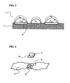
- FIG. 3 is a sectional view showing a model of diamond joined interface brazed according to the present invention.
- FIG. 4 is an exploded perspective view showing an example of a method by which diamond is brazed according to the present invention.
- FIG. 5 is a schematic front view of a brazing equipment used for the present invention.
- FIG. 1 shows a side view in which a diamond is brazed on a metal substrate using a brazing-filler material according to the present invention.
- Reference numeral 1 represents a metal substrate
- 2 represents a diamond joined
- 3 represents a brazing-filler material, in the figure.
- 0.001 to 5 mass %, preferably not more than 2.0 mass % of vanadium is contained in a silver-copper eutectic brazing-filler material.
- ⁇ ss represents an interatomic distance in a diamond as a substrate
- off represents an interatomic distance in a deposited film.
- a crystal lattice misfit ⁇ in case of vanadium carbide is shown in TABLE 1 together with those in titanium carbide and zirconium carbide.
- vanadium carbide 35 is preferably formed in a shape of islands in an interface zone between the brazing-filler material 3 and the diamond 2 as is shown in a model of FIG. 2 .
- the island 35 of vanadium carbide has a diameter of approximately 100 nm and a thickness of approximately 10 nm.
- a structure was provided in which silver in the silver-copper brazing-filler material precipitated on the islands of vanadium carbides, and copper joined onto the diamond among the islands of vanadium carbides.
- a cross section of the joined portion probably had a structure as a model shown in FIG. 3 .
- vanadium carbides are formed in a shape of islands, thereby the diamond is joined firmly to the brazing-filler material, while the diamond surface is not eroded by the vanadium carbide but an interface having a beautiful view is maintained.
- d[uvw]c represents a nearest interatomic distance in a low index plane of a heterogeneous nucleus (added metal)
- d[uvw]s represents a nearest interatomic distance in a low index plane of a solid crystal (base metal)
- ⁇ represents an angle formed between both the nearest directions of the substances.
- An amount of vanadium added is 0.001 to 5 mass %, preferably not more than 2.0 mass %, and theoretical amount of vanadium is 0.001 mass %.
- an amount of vanadium added is in a range of 0.001 to 5 mass %, a diamond can be joined onto a metallic material.
- an amount of vanadium added exceeds 0.5 mass %, unreacted vanadium may precipitate on a joined interface as small particles.
- a reaction product of vanadium carbide is formed in a joined interface between the diamond and the brazing-filler material so much that the joined interface of the diamond gradually increases its roughness.
- an amount of vanadium added to a brazing-filler material is 0.001 to 2.0 mass %, and preferably not more than 0.5 mass %. As in a case of tools etc., when esthetic viewpoint is not required, up to 5 mass % of vanadium may be contained.
- vanadium carbides formed in a joined interface of diamond have a shape of islands, and, an area of islands of vanadium carbides in a joined interface is preferably less than 23% of the joined interface area. A ratio exceeding 23% gives a rough joined interface.
- An amount of vanadium added to a brazing-filler material can be presumed from following information. First, it may be presumed from following information that supercooling may arise in a silver-copper eutectic brazing-filler material. That is, in an equilibrium system, conditions for constitutional undercooling to arise are given by following equation. G L V ⁇ m e ⁇ C o ⁇ ( 1 - k e ) k e ⁇ D L
- a radius of silver hemisphere (critical radius of nucleus: r*) formed on an island of vanadium carbides is related to an interface turbulence wavelength ⁇ of perturbation of solid-liquid interface.
- G homo represents a Gibbs free energy of homogeneous nucleus, r solidification nuclear radius, ⁇ LS surface free energy, Tm melting point, ⁇ density of a solid, ⁇ H solidification latent heat, and ⁇ T degree of undercooling.
- supposing island-like reaction products 35 which have a radius of r* Ag are formed, since one island exists in a parallelogram with one side ⁇ , a percentage of reaction product occupied in the joined interface is obtained.
- a state where less than 23% of the joined interface is covered by the reaction product may be recognized as a state where a sound joined interface is given. It is assumed that one island-like reaction product has a cylindrical form, and if 10 nm determined from actual measurement is used as thickness, an amount of vanadium added will be determined.
- FIGS. 4 and 5 A method for brazing diamonds on a metal substrate using a brazing-filler material of the present invention is shown in FIGS. 4 and 5 , as examples.
- 42 Invar alloy substrate (0.2 mm in thickness, 55 mm in length) was used as a metal substrate 1 , and an artificial diamond 2 (0.6 mm in thickness) was joined on it.
- the joined face of the artificial diamond was set as plane (111).
- two brazing-filler material plates 31 made of silver-copper eutectic alloy that had a dimension of 6 mm ⁇ 6 mm ⁇ thickness of 0.05 mm were used.
- VHx vanadium hydride powder
- a brazing equipment had a constitution in which both of ends of specimen (metal substrate 1 ) were fixed with screws in a specimen electrode holder 5 currently supported by springs 51 .
- the alloy substrate generated heat by current flowing through the 42 Invar alloy substrate.
- a load 53 was added toward a lower direction to the diamonds 3 to be joined, the load 53 acted as a copper chiller so that diamond upper surfaces may be cooled.
- thermocouples 54 and 55 were attached to the copper chiller and the brazing-filler material plate, respectively.
- the temperature was set to a temperature of 10K or more above a melting point of the brazing-filler material (melting point of an eutectic alloy having a composition of silver ⁇ 39.9 at % copper is about 1052K) so that vanadium hydride decomposed to form an alloy with the brazing-filler material, and that vanadium reacted with carbon to be joined on the surfaces of the diamonds to form reaction products (vanadium carbides).
- degree of vacuum at the time of brazing was set to 1 ⁇ 10 ⁇ 2 Pa.
- Islands 35 of vanadium carbides were formed in the joined face of the diamonds, as shown in FIGS. 2 and 3 , by cooling from a side of the diamonds to carry out unidirectional solidification using a copper chiller at the time of the brazing. Firstly silver solidified on it. On the other hand, it is thought that copper precipitated on the diamonds directly. And then the brazing-filler material alloy precipitated on them to join the diamonds. Although this unidirectional solidification is not necessarily required, unidirectional solidification made formation of the island 35 of vanadium carbide easy.
- Vanadium hydride was used here. It is because metal vanadium is active and will react with oxygen rapidly to give oxide in atmospheric condition, while vanadium hydride is stable, and it emits hydrogen easily by heating and resulting vanadium is alloyed with the brazing-filler material.
- a gold-copper brazing-filler material or a gold-silver-copper brazing-filler material may be used.
- a constitution having a clad beforehand with vanadium as a powdered vanadium hydride, and a constitution in which metallic vanadium is alloyed in a brazing-filler material may also be used.
- a brazing-filler material that contains at least one selected from a group consisting of gold and silver, and copper as main ingredients, and that further contains vanadium is used, and therefore a diamond may be firmly and stably brazed on a metal substrate.
- Amount of vanadium added may be set as 0.001 to 5 mass %, and when a brazing-filler material contains 0.001 to 2.0 mass % of vanadium, vanadium carbide is formed in a shape of islands in a joined interface of the diamond, and thus further stabilized brazing may be attained. Since the joined surface of the diamond is not eroded when vanadium is not more than 0.5 mass %, a surface with a beautiful view can be maintained.
- brazing-filler material is performed from a side of the diamond to advance solidification, islands of vanadium carbide are easily formed in the diamond joined interface, and thereby stable brazing is accomplished.
Abstract
When a diamond is brazed to a metal substrate, while obtaining a stable joining strength, a joined interface of the diamond is not eroded to provide a good joint with a beautiful view. A brazing-filler material containing at least one selected from a group consisting of gold and silver, and copper as principal components, and further containing 0.001 to 5 mass % of vanadium is used. Preferably, a vanadium content is not more than 2.0 mass %, and more preferably not more than 0.5 mass %. Using this brazing-filler material, unidirectional solidification is performed from a side of diamond to form vanadium carbide in a joined interface in a shape of islands, and thereby an interface having a beautiful view with stable joining strength can be obtained. In addition, strong joining is possible also by a usual solidification method.
Description
1. Field of the Invention
The present invention relates to a brazing-filler material for joining a diamond and a metal and to a brazing method using the brazing-filler material.
2. Description of the Related Art
In diamond accessories, diamond tools, ceramic tools, etc., in plenty of cases, diamonds or ceramics are used being joined to substrates currently made of metal, such as plinth and shank. A silver-copper eutectic brazing-filler material containing titanium is used for the joining. The silver-copper eutectic brazing-filler material containing titanium is called TiCuSil, and titanium foil disperses to form fragment in a shape of flakes in an alloy having a eutectic composition of silver-copper. Diamonds or ceramics brazed to a substrate by the silver-copper eutectic brazing-filler material have a higher strength as compared with those joined by adhesives etc.
In diamonds bonded to a metal substrate using TiCuSil brazing-filler material, it is known that brazed interfaces of the diamonds provide black coloring. Since the brazed interface showing black can be observed through upper surface of the diamond, the TiCuSil material is not preferable for accessories. However, most coloring has been ignored in the case where ceramics had been joined by TiCuSil.
When a diamond is joined by TiCuSil, titanium in the brazing-filler material reacts with carbon in the diamond to form titanium carbide, and the titanium carbide existing between the diamond and the brazing-filler material bonds the diamond with the brazing-filler material. It became clear that, when titanium carbide is formed, irregularity is caused on the diamond surface, and thereby light was scattered on it, and the joined interface of the diamond provided black coloring.
And, the TiCuSil brazing-filler material is widely used also in manufacturing diamond tools, and it is known that the brazing-filler material occasionally provides a low joining strength. When metal works are processed using a tool having low joining strength, diamonds are sometimes removed from the tool to give contact between metal works and a shank, and both of the product and the tool might receive damage. Even if a low joining strength happens to be formed between diamonds and shanks, the defect has been considered to be caused by unskilled brazing technique without sufficient pursuit of cause.
Then, a first object of the present invention is to provide a brazing-filler material that provides stable joining strength when a diamond is brazed to a metal substrate, and a method for brazing with the brazing-filler material.
And, another object of the present invention is to provide a brazing-filler material that is suitable for joining of a diamond for ornament, and that does not provide black coloring in a joined interface, and a method for brazing with the brazing-filler material.
As a result of the research performed by the present inventors for a brazing-filler material suitable for joining of a diamond and for a preferable joined interface, based on theoretical analysis of joined interface at the time of brazing, the present invention has been accomplished.
A brazing-filler material of the present invention is a brazing-filler material containing at least one selected from a group consisting of gold and silver, and copper as principal components, and further containing 0.001 to 5 mass % of vanadium. Preferably it contains 0.001 to 2.0 mass % of vanadium. More preferably it contains 0.001 to 0.5 mass % of vanadium.
In a brazing-filler material of the present invention, a vanadium content is most preferably not less than 0.001 mass % and not more than 0.5 mass % in order to braze diamonds onto a metal substrate. When vanadium content exceeds 0.5 mass %, vanadium that remains without being melted may be observed in the joined interface as small particles. However, in not more than 2.0 mass %, as long as observed macroscopically, a degree of providing black coloring is not significant. Although joining of diamond is possible when an amount of vanadium exceeds 2.0 mass %, such an amount is not required. When a vanadium content exceeds 2.0 mass %, excessive vanadium is discharged and the brazing-filler material may lose its metallic luster in the joined interface. Considering that vanadium tends to segregate in the brazing-filler material, up to 5 mass % of vanadium may be contained when beautiful view is not considered as important.
In a brazing-filler material of the present invention, at least one selected from a group consisting of gold and silver, and copper are preferably contained in a eutectic composition.
In a brazing-filler material of the present invention, vanadium hydride may be used as vanadium, and moreover a brazing-filler material is used in which vanadium hydride containing 0.001 to 2.0 mass % of vanadium to the whole brazing-filler material is put between brazing-filler material plates that contain at least one selected from a group consisting of gold and silver, and copper as principal components or ingredients. The brazing-filler material preferably contains 0.001 to 0.5 mass % of vanadium. When using vanadium hydride as vanadium, since vanadium is uniformly distributed in the brazing-filler material, an amount of vanadium is set as at most 2.0 mass %.
In a method for brazing a diamond by the present invention, a brazing-filler material containing at least one selected from a group consisting of gold and silver, and copper as principal components, and containing 0.001 to 5 mass % of vanadium is placed on a metal substrate to be joined with, and the diamond is placed thereon, and subsequently, after the brazing-filler material is heated and melted, it is cooled and thus the brazing-filler material is solidified between the diamond and the metal substrate. In the method, as the brazing-filler material, brazing-filler material plates may be used in which vanadium hydride containing 0.001 to 2.0 mass % of vanadium to the whole brazing material is put between the brazing-filler material plates that contain at least one selected from a group consisting of gold and silver, and copper as principal components. And it is preferable that an amount of vanadium contained in the brazing-filler material is 0.001 to 0.5 mass %. A heating temperature of a brazing-filler material on brazing is preferably 10K (Kelvin) or more above a melting point of the brazing-filler material. In addition, in the method for brazing a diamond according to the present invention, after a brazing-filler material is heated and melted, it is preferable that cooling is performed from a side of the diamond to solidify the brazing-filler material. That is, it is preferable that unidirectional solidification of the brazing-filler material is carried out from a side of the diamond.
When a diamond is brazed according to the present invention, vanadium carbides are formed in a joined interface between the diamond and the brazing-filler material in a shape of minute islands. The island-like vanadium carbides are firmly joined with the diamond, and the diamond is joined with the brazing-filler material. Since a surface of the diamond is not eroded and large irregularity is not formed on the surface, an interface having a beautiful view may be obtained.
A crystal lattice misfit η is used to describe a growth of a thin film, and it is represented by following equation.
Here, σss represents an interatomic distance in a diamond as a substrate, and off represents an interatomic distance in a deposited film. A crystal lattice misfit η in case of vanadium carbide is shown in TABLE 1 together with those in titanium carbide and zirconium carbide.
| TABLE 1 | |||
| Carbide | η | ||
| VC | 0.1607 | ||
| TiC | 0.2125 | ||
| ZrC | 0.3141 | ||
As is clear in TABLE 1, the crystal lattice misfit of vanadium carbide is smallest in them, and it is expected that the misfit of vanadium carbide will increase a joining strength with diamond.
Detailed observation of a structure of joined portion showed clearly that vanadium carbide 35 is preferably formed in a shape of islands in an interface zone between the brazing-filler material 3 and the diamond 2 as is shown in a model of FIG. 2. The island 35 of vanadium carbide has a diameter of approximately 100 nm and a thickness of approximately 10 nm. A structure was provided in which silver in the silver-copper brazing-filler material precipitated on the islands of vanadium carbides, and copper joined onto the diamond among the islands of vanadium carbides. A cross section of the joined portion probably had a structure as a model shown in FIG. 3.
In a diamond joined interface, vanadium carbides are formed in a shape of islands, thereby the diamond is joined firmly to the brazing-filler material, while the diamond surface is not eroded by the vanadium carbide but an interface having a beautiful view is maintained.
This model will be understood using a degree of plane mismatching introduced in order to discuss influence of added metallic elements over melting point lowering of metal/alloy. This may be obtained by averaging differences of atomic intervals in three dimensions so that a degree of plane mismatching δ may be applied also to substances that have different crystal structures, and the degree of plane mismatching is represented by following equation.
In the equation, d[uvw]c represents a nearest interatomic distance in a low index plane of a heterogeneous nucleus (added metal), d[uvw]s represents a nearest interatomic distance in a low index plane of a solid crystal (base metal), and θ represents an angle formed between both the nearest directions of the substances. When a priority solidification of a liquid metal is examined, in the above equation, an interatomic distance of stable site of a compound (vanadium carbide) in a brazing face is adopted for d[uvw]s. This is because a joined surface is set as basis. And a nearest interatomic distance in a low index plane of solidifying metal is adopted for d[uvw]c. Degrees of interface mismatching δ of a variety of substances are shown in TABLE 2. In a combination of vanadium carbide and silver, a degree of interface mismatching δ gives a value of 0.01298, a value between copper and diamond gives 0.01327, and each of these shows small value. Therefore, priority solidification of silver is expectable on vanadium carbide reaction nucleant, and copper solidification is expectable on the diamond. This fact illustrates that a joined interface like a silver mirror having good adhesiveness will be formed on vanadium carbide. On the other hand, a degree of mismatching δ between vanadium carbide and copper shows a large value of 0.13100, and copper probably does not adhere onto vanadium carbide.
| TABLE 2 | |||||
| Solid | Film | Direction | δ | ||
| Diamond | Copper | (100) || (100) | 0.01327 | ||
| Diamond | Silver | (100) || (100) | 0.1271 | ||
| TiC | Copper | (100) || (100) | 0.1952 | ||
| TiC | Silver | (100) || (100) | 0.05728 | ||
| TiC | Silver | (111) || (111) | 0.05418 | ||
| VC | Silver | (111) || (111) | 0.01298 | ||
| VC | Copper | (111) || (111) | 0.13100 | ||
An amount of vanadium added is 0.001 to 5 mass %, preferably not more than 2.0 mass %, and theoretical amount of vanadium is 0.001 mass %. When an amount of vanadium added is in a range of 0.001 to 5 mass %, a diamond can be joined onto a metallic material. However, when an amount of vanadium added exceeds 0.5 mass %, unreacted vanadium may precipitate on a joined interface as small particles. And a reaction product of vanadium carbide is formed in a joined interface between the diamond and the brazing-filler material so much that the joined interface of the diamond gradually increases its roughness. When an amount of vanadium added is in a range of up to 2.0 mass %, there is little scattering of light by the joined interface, but when addition exceeds the value, the joined interface becomes to show black. If vanadium exceeds 2.0 mass %, scattering of light by the joined interface increases and the interface looks black. Therefore, in order to prevent a diamond for ornament from showing black, an amount of vanadium added to a brazing-filler material is 0.001 to 2.0 mass %, and preferably not more than 0.5 mass %. As in a case of tools etc., when esthetic viewpoint is not required, up to 5 mass % of vanadium may be contained.
As mentioned above, vanadium carbides formed in a joined interface of diamond have a shape of islands, and, an area of islands of vanadium carbides in a joined interface is preferably less than 23% of the joined interface area. A ratio exceeding 23% gives a rough joined interface.
An amount of vanadium added to a brazing-filler material can be presumed from following information. First, it may be presumed from following information that supercooling may arise in a silver-copper eutectic brazing-filler material. That is, in an equilibrium system, conditions for constitutional undercooling to arise are given by following equation.
When me represents a gradient of liquid phase line and is 4.58K/at %, Co represents a solute concentration (copper concentration is about 39.9 at % in silver-copper eutectic system), DL represents a diffusion coefficient in liquid phase and is 5×10⁻⁹m2/s, and ke represents an equilibrium distribution coefficient and is 0.356, GL/V≦6.562×1010. In brazing conditions, GL is a temperature gradient and V is a solidifying speed. These values are those satisfied in usual brazing conditions in vacuum.
A radius of silver hemisphere (critical radius of nucleus: r*) formed on an island of vanadium carbides is related to an interface turbulence wavelength λ of perturbation of solid-liquid interface. A critical radius of nucleus r* is obtained from
In the equations, Ghomo represents a Gibbs free energy of homogeneous nucleus, r solidification nuclear radius, σLS surface free energy, Tm melting point, ρ density of a solid, ΔH solidification latent heat, and ΔT degree of undercooling. Degree of undercooling was set as 2K based on a measured value for silver in a brazing equipment. From a perturbation model in a joined interface inFIG. 3 , it is assumed that a growth of heterogeneous nucleus occurred to r*Ag by priority solidification of silver. r*Ag may be estimated as 113.4 nm from ΔH/Tm=11.3/1235 kJ/mol·K, and σLS=101×10−3 J/m2. A condition in which cell joined interface is produced is given by
λ≧4r* Ag
In the equations, Ghomo represents a Gibbs free energy of homogeneous nucleus, r solidification nuclear radius, σLS surface free energy, Tm melting point, ρ density of a solid, ΔH solidification latent heat, and ΔT degree of undercooling. Degree of undercooling was set as 2K based on a measured value for silver in a brazing equipment. From a perturbation model in a joined interface in
λ≧4r* Ag
As shown in FIGS. 2 and 3 , supposing island-like reaction products 35 which have a radius of r*Ag are formed, since one island exists in a parallelogram with one side λ, a percentage of reaction product occupied in the joined interface is obtained. A state where less than 23% of the joined interface is covered by the reaction product may be recognized as a state where a sound joined interface is given. It is assumed that one island-like reaction product has a cylindrical form, and if 10 nm determined from actual measurement is used as thickness, an amount of vanadium added will be determined. If a dimension of silver-copper eutectic brazing-filler material is assumed to be 6 mm×6 mm×thickness of 0.1 mm, a theoretical amount of vanadium added to this will be 0.4 microgram, and it means 0.001 mass %.
A method for brazing diamonds on a metal substrate using a brazing-filler material of the present invention is shown in FIGS. 4 and 5 , as examples. In the examples, 42 Invar alloy substrate (0.2 mm in thickness, 55 mm in length) was used as a metal substrate 1, and an artificial diamond 2 (0.6 mm in thickness) was joined on it. The joined face of the artificial diamond was set as plane (111). As is shown in FIG. 4 , two brazing-filler material plates 31 made of silver-copper eutectic alloy that had a dimension of 6 mm×6 mm×thickness of 0.05 mm were used. One of the plates was placed on the 42 Invar alloy substrate, and a required quantity of vanadium hydride powder (VHx) 32 (grain size that passes through 0.075 mm mesh) was further placed on it. Furthermore, the other brazing-filler material plate 31 was arranged on it, and diamonds 2 to be joined were placed thereon.
As an outline front view is shown in FIG. 5 , a brazing equipment had a constitution in which both of ends of specimen (metal substrate 1) were fixed with screws in a specimen electrode holder 5 currently supported by springs 51. When voltage was applied between terminals 52 in both ends of the specimen electrode holder 5, the alloy substrate generated heat by current flowing through the 42 Invar alloy substrate. While a load 53 was added toward a lower direction to the diamonds 3 to be joined, the load 53 acted as a copper chiller so that diamond upper surfaces may be cooled. In order to measure temperatures of the copper chiller and the brazing-filler material plate at the time of brazing, thermocouples 54 and 55 were attached to the copper chiller and the brazing-filler material plate, respectively.
Electric current was applied to the 42 Invar alloy substrate and the brazing-filler material was heated up to about 1065K to perform brazing. The temperature was set to a temperature of 10K or more above a melting point of the brazing-filler material (melting point of an eutectic alloy having a composition of silver −39.9 at % copper is about 1052K) so that vanadium hydride decomposed to form an alloy with the brazing-filler material, and that vanadium reacted with carbon to be joined on the surfaces of the diamonds to form reaction products (vanadium carbides). In addition, degree of vacuum at the time of brazing was set to 1×10⁻² Pa. Islands 35 of vanadium carbides were formed in the joined face of the diamonds, as shown in FIGS. 2 and 3 , by cooling from a side of the diamonds to carry out unidirectional solidification using a copper chiller at the time of the brazing. Firstly silver solidified on it. On the other hand, it is thought that copper precipitated on the diamonds directly. And then the brazing-filler material alloy precipitated on them to join the diamonds. Although this unidirectional solidification is not necessarily required, unidirectional solidification made formation of the island 35 of vanadium carbide easy.
Vanadium hydride was used here. It is because metal vanadium is active and will react with oxygen rapidly to give oxide in atmospheric condition, while vanadium hydride is stable, and it emits hydrogen easily by heating and resulting vanadium is alloyed with the brazing-filler material.
In a description above, although the silver-copper eutectic brazing-filler material was used, a gold-copper brazing-filler material or a gold-silver-copper brazing-filler material may be used. A constitution having a clad beforehand with vanadium as a powdered vanadium hydride, and a constitution in which metallic vanadium is alloyed in a brazing-filler material may also be used.
The same method as in the above described Example was repeated, and artificial diamonds were joined on a 42 Invar alloy substrate. A silver-copper eutectic alloy brazing-filler material of the present invention was used here, amount of added vanadium hydride was varied for the amount of vanadium to brazing-filler material to be contained by 0.01, 0.2, 0.5, 1.0, and 2.0 mass %, respectively. Evaluation for joined portions of specimens of the artificial diamonds thus joined was performed. Coloring of the joined portion was checked by macroscopic and microscopic observations, and joined interfaces were shaved off and observed using a non-contacting atomic force microscope (NC-AFM). Results are shown in TABLE 3. As is clear in Table 3, joined portions in which vanadium is contained up to 0.5 mass % showed silver white coloring. When 1.0 mass % of vanadium was contained, it showed silver coloring although small particles were observed. When 2.0 mass % of vanadium was contained, the joined portion showed black coloring. And in observation result of NC-AFM, islands were clearly observed in specimens containing vanadium of 1.0 mass % or less.
| TABLE 3 | |||
| Speci- | Amount | ||
| men | of V | Formation of VC islands | |
| num- | con- | Coloring of brazed surface | observed by OM |
| ber | tained | by macroscopic observation | (and AFM) |
| 1 | 0.01 | Silver-white | Observed |
| |
|||
| 2 | 0.2 | Silver-white | Observed |
| 3 | 0.5 | Silver-white | Observed |
| 4 | 1.0 | Silver-white (small particles | Observed |
| not completely melted were | (Islands are partially | ||
| observed) | connected) | ||
| 5 | 2.0 | Black coloring with a | Observed a little |
| diameter of about 2 mm | (Partially making a layer) | ||
| *OM: Optical Microscope AFM: Atomic Force Microscope | |||
The observation result shows that inclusion of vanadium of not more than 0.5 mass % is most preferable. Even if an amount of vanadium contained exceeds 2.0 mass %, although joining is possible, since joined face gives black coloring, it is scarcely suitable for ornamental use. Since vanadium tends to be uniformly distributed in a brazing-filler material when vanadium is added as vanadium hydride, it is desirable to set to 2.0 mass % or less.
In order to investigate occurrence of defect in joining, a conventional TiCuSil brazing-filler material was used first, and 20 diamonds were joined onto a 42 Invar alloy substrate. A rate of occurrence of defect in joining when crystal planes (100), (110) and (111) of diamond respectively were brazed is shown in TABLE 4. When the plane (110) of the diamond was joined, high percentage defective was obtained, and remarkable percentage defective was obtained also in plane (111).
When the plane (111) of the diamond was joined using a brazing-filler material (vanadium of 0.3 mass % was contained in a silver-copper eutectic alloy) of the present invention, as shown in TABLE 4, defect in joining showed 0%.
| TABLE 4 | ||
| Joined plane of | Percentage defective in | |
| Brazing-filler material | diamond | joining |
| TiCuSil | Plane (100) | 0% |
| Brazing-filler material | Plane (110) | 43% |
| Plane (111) | 29% | |
| Brazing-filler material | Plane (111) | 0% |
| of the present invention | ||
In the present invention, a brazing-filler material that contains at least one selected from a group consisting of gold and silver, and copper as main ingredients, and that further contains vanadium is used, and therefore a diamond may be firmly and stably brazed on a metal substrate. Amount of vanadium added may be set as 0.001 to 5 mass %, and when a brazing-filler material contains 0.001 to 2.0 mass % of vanadium, vanadium carbide is formed in a shape of islands in a joined interface of the diamond, and thus further stabilized brazing may be attained. Since the joined surface of the diamond is not eroded when vanadium is not more than 0.5 mass %, a surface with a beautiful view can be maintained.
And when brazing is performed by a method for brazing of the present invention, cooling of the brazing-filler material is performed from a side of the diamond to advance solidification, islands of vanadium carbide are easily formed in the diamond joined interface, and thereby stable brazing is accomplished.
Claims (25)
1. A method for brazing diamond, comprising the steps of:
placing on a metal substrate to be joined, a brazing-filler material consisting essentially of vanadium of 0.001 to 2.0 mass % and the balance being principal components consisting of copper and at least one selected from the group consisting of gold and silver,
placing diamond thereon,
heating and melting the brazing-filler material, and
subsequently cooling to solidify the brazing-filler material and to precipitate vanadium carbides in an island shape on a joined interface between the brazing-filler material and the diamond to provide the joined interface with less roughness than that showing black.
2. A method for brazing diamond according to claim 1 , wherein a vanadium content is 0.001 to 0.5 mass % in the brazing-filler material.
3. A method for brazing diamond according to claim 2 , wherein the brazing-filler material is heated at a temperature 10 K or more above a melting point of a brazing-filler material.
4. A method for brazing according to claim 3 , wherein cooling is performed from a side of the diamond to solidify the brazing-filler material after the brazing-filler material is heated and melted.
5. A brazed diamond comprising:
a metal substrate, and
a diamond brazed on the metal substrate with a brazing-filler material, between the metal substrate and the diamond, consisting essentially of vanadium of 0.001 to 2.0 mass % and the balance being principal components consisting of copper and at least one selected from the group consisting of gold and silver,
wherein the brazing-filler material has precipitated vanadium carbides in an island shape on a joined interface between the brazing-filler material and the diamond, and the joined interface has less roughness than that showing black.
6. A brazed diamond according to claim 5 , wherein a vanadium content is 0.001 to 0.5 mass % in the brazing-filler material.
7. A brazed diamond according to claim 5 , wherein the principal components are in a eutectic composition of copper and at least one of gold and/or silver.
8. A brazed diamond according to claim 5 , wherein the precipitated vanadium carbides in an island shape is less than 23% of the joined interface area.
9. A brazed diamond according to claim 6 , wherein the principal components are in a eutectic composition of copper and at least one of gold and/or silver.
10. A brazed diamond according to claim 5 , wherein the principal components consist of copper and silver.
11. A brazed diamond according to claim 10 , wherein a vanadium content is 0.001 to 0.5 mass % in the brazing-filler material.
12. A brazed diamond according to claim 10 , wherein the principal components are in a eutectic composition of copper and silver.
13. A brazed diamond according to claim 11 , wherein the principal components are in a eutectic composition of copper and silver.
14. A brazed diamond according to claim 5 , wherein the principal components consist of copper, silver and gold.
15. A brazed diamond according to claim 14 , wherein a vanadium content is 0.001 to 0.5 mass % in the brazing-filler material.
16. A brazed dd according to claim 14 , wherein the principal components are in a eutectic composition of copper, silver and gold.
17. A brazed diamond according to claim 15 , wherein the principal components are in a eutectic composition of copper, silver and gold.
18. An ornamental brazed diamond comprising:
a metal substrate, and
a diamond brazed on the metal substrate with a brazing-filler material, between the metal substrate and the diamond, consisting essentially of vanadium of 0.001 to 2.0 mass % and the balance being principal components consisting of copper and at least one selected from the group consisting of gold and silver,
wherein the brazing-filler material has precipitated vanadium carbides in an island shape on a joined interface between the brazing-filler material and the diamond, and the joined interface has less roughness than that showing black.
19. An ornamental diamond according to claim 18 , wherein a vanadium content is 0.001 to 0.5 mass % in the brazing-filler material.
20. An ornamental diamond according to claim 18 , wherein the principal components are in a eutectic composition of copper and at least one of gold and/or silver.
21. An ornamental diamond according to claim 19 , wherein the principal components are in a eutectic composition of copper and at least one of gold and/or silver suitable to the ornamental use.
22. A method for brazing diamond, comprising the steps of:
placing on a metal substrate to be joined a brazing-filler material that contains vanadium of 0.001 to 0.5 mass % and principle components consisting of copper and at least one selected from the group consisting of gold and silver,
placing diamond thereon,
heating and melting the brazing-filler material at a temperature 10 K or more above a melting point of the brazing-filler material, and
subsequently cooling from a side of the diamond to solidify the brazing-filler material.
23. A method for brazing diamond according to claim 22 , wherein the step of placing on a metal substrate to be joined a brazing-filler material comprises:
providing, on the metal substrate, plates composed of copper and at least one selected from the group consisting of gold and silver and
providing vanadium hydride powder containing vanadium of 0.001 to 0.5 mass % to the whole brazing-filter material between the plates.
24. A brazed diamond comprising:
a diamond;
brazing material including 0.001 to 2.0 mass. % vanadium, copper and one of gold and silver, said brazing material being connected to said diamond by precipitated vanadium carbides arranged in island shapes at an interface between said diamond and said brazing material, said interface having a surface roughness displaying a brightness greater than black.
25. A diamond in accordance with claim 24 , wherein:
a substrate is provided, said diamond with said brazing material is arranged on said substrate in an ornamental arrangement;
said brazing material is arranged on said diamond to have said surface roughness of said interface display a silver white color.
Applications Claiming Priority (2)
| Application Number | Priority Date | Filing Date | Title |
|---|---|---|---|
| JP2001-310937 | 2001-10-09 | ||
| JP2001310937A JP3795786B2 (en) | 2001-10-09 | 2001-10-09 | Brazed diamond and diamond brazing method |
Publications (2)
| Publication Number | Publication Date |
|---|---|
| US20030080177A1 US20030080177A1 (en) | 2003-05-01 |
| US6889890B2 true US6889890B2 (en) | 2005-05-10 |
Family
ID=19129846
Family Applications (1)
| Application Number | Title | Priority Date | Filing Date |
|---|---|---|---|
| US10/262,741 Expired - Fee Related US6889890B2 (en) | 2001-10-09 | 2002-10-02 | Brazing-filler material and method for brazing diamond |
Country Status (5)
| Country | Link |
|---|---|
| US (1) | US6889890B2 (en) |
| EP (1) | EP1302273B1 (en) |
| JP (1) | JP3795786B2 (en) |
| CN (1) | CN1254346C (en) |
| DE (1) | DE60225395T2 (en) |
Cited By (79)
| Publication number | Priority date | Publication date | Assignee | Title |
|---|---|---|---|---|
| US20070290545A1 (en) * | 2006-06-16 | 2007-12-20 | Hall David R | An Attack Tool for Degrading Materials |
| US20070290546A1 (en) * | 2006-06-16 | 2007-12-20 | Hall David R | A Wear Resistant Tool |
| US20080036280A1 (en) * | 2006-08-11 | 2008-02-14 | Hall David R | Pick Assembly |
| US20080036282A1 (en) * | 2006-08-11 | 2008-02-14 | Hall David R | Attack Tool |
| US20080036176A1 (en) * | 2006-08-09 | 2008-02-14 | Schuettenberg Donald W | Front Tow Extended Saddle |
| US20080036269A1 (en) * | 2006-08-11 | 2008-02-14 | Hall David R | Hollow Pick Shank |
| US20080036279A1 (en) * | 2006-08-11 | 2008-02-14 | Hall David R | Holder for a degradation assembly |
| US20080036276A1 (en) * | 2006-08-11 | 2008-02-14 | Hall David R | Lubricated Pick |
| US20080036274A1 (en) * | 2006-08-11 | 2008-02-14 | Hall David R | Sleeve in a Degradation Assembly |
| US20080036283A1 (en) * | 2006-08-11 | 2008-02-14 | Hall David R | Attack Tool |
| US20080036272A1 (en) * | 2006-08-11 | 2008-02-14 | Hall David R | Washer for a degradation assembly |
| US20080035381A1 (en) * | 2006-08-11 | 2008-02-14 | Hall David R | Lubricating drum |
| US20080036273A1 (en) * | 2006-08-11 | 2008-02-14 | Hall David R | Washer for a Degradation Assembly |
| US20080036275A1 (en) * | 2006-08-11 | 2008-02-14 | Hall David R | Retainer Sleeve in a Degradation Assembly |
| US20080036271A1 (en) * | 2006-08-11 | 2008-02-14 | Hall David R | Method for Providing a Degradation Drum |
| US20080035386A1 (en) * | 2006-08-11 | 2008-02-14 | Hall David R | Pick Assembly |
| US20080036278A1 (en) * | 2006-08-11 | 2008-02-14 | Hall David R | Attack tool |
| US7347292B1 (en) | 2006-10-26 | 2008-03-25 | Hall David R | Braze material for an attack tool |
| US20080088172A1 (en) * | 2006-08-11 | 2008-04-17 | Hall David R | Holder Assembly |
| US20080099250A1 (en) * | 2006-10-26 | 2008-05-01 | Hall David R | Superhard Insert with an Interface |
| US20080099251A1 (en) * | 2006-10-26 | 2008-05-01 | Hall David R | High impact resistant tool |
| US20080115977A1 (en) * | 2006-08-11 | 2008-05-22 | Hall David R | Impact Tool |
| US20080129104A1 (en) * | 2006-08-11 | 2008-06-05 | Hall David R | Impact Tool |
| US7396086B1 (en) | 2007-03-15 | 2008-07-08 | Hall David R | Press-fit pick |
| US20080185468A1 (en) * | 2006-08-11 | 2008-08-07 | Hall David R | Degradation insert with overhang |
| US20080197691A1 (en) * | 2006-08-11 | 2008-08-21 | Hall David R | Locking fixture for a degradation assembly |
| US20080211290A1 (en) * | 2006-08-11 | 2008-09-04 | Hall David R | Tapered Bore in a Pick |
| US20080250724A1 (en) * | 2007-04-12 | 2008-10-16 | Hall David R | High Impact Shearing Element |
| US20080264697A1 (en) * | 2006-08-11 | 2008-10-30 | Hall David R | Retention for an Insert |
| US20080284235A1 (en) * | 2007-05-15 | 2008-11-20 | Hall David R | Spring Loaded Pick |
| US20080284234A1 (en) * | 2007-05-14 | 2008-11-20 | Hall David R | Pick with a Reentrant |
| US20080309149A1 (en) * | 2006-08-11 | 2008-12-18 | Hall David R | Braze Thickness Control |
| US20080309146A1 (en) * | 2006-08-11 | 2008-12-18 | Hall David R | Degradation assembly shield |
| US20090066149A1 (en) * | 2007-09-07 | 2009-03-12 | Hall David R | Pick with Carbide Cap |
| US7568770B2 (en) | 2006-06-16 | 2009-08-04 | Hall David R | Superhard composite material bonded to a steel body |
| US20090200857A1 (en) * | 2006-08-11 | 2009-08-13 | Hall David R | Manually Rotatable Tool |
| US20090200855A1 (en) * | 2006-08-11 | 2009-08-13 | Hall David R | Manually Rotatable Tool |
| US20090267403A1 (en) * | 2006-08-11 | 2009-10-29 | Hall David R | Resilient Pick Shank |
| US7628233B1 (en) | 2008-07-23 | 2009-12-08 | Hall David R | Carbide bolster |
| US7648210B2 (en) | 2006-08-11 | 2010-01-19 | Hall David R | Pick with an interlocked bolster |
| US7669938B2 (en) | 2006-08-11 | 2010-03-02 | Hall David R | Carbide stem press fit into a steel body of a pick |
| US20100054875A1 (en) * | 2006-08-11 | 2010-03-04 | Hall David R | Test Fixture that Positions a Cutting Element at a Positive Rake Angle |
| US7722127B2 (en) | 2006-08-11 | 2010-05-25 | Schlumberger Technology Corporation | Pick shank in axial tension |
| US7740414B2 (en) | 2005-03-01 | 2010-06-22 | Hall David R | Milling apparatus for a paved surface |
| US20100264721A1 (en) * | 2009-04-16 | 2010-10-21 | Hall David R | Seal with Rigid Element for Degradation Assembly |
| US20100263939A1 (en) * | 2006-10-26 | 2010-10-21 | Hall David R | High Impact Resistant Tool with an Apex Width between a First and Second Transitions |
| US20100275425A1 (en) * | 2009-04-29 | 2010-11-04 | Hall David R | Drill Bit Cutter Pocket Restitution |
| US7832808B2 (en) | 2007-10-30 | 2010-11-16 | Hall David R | Tool holder sleeve |
| US20110008532A1 (en) * | 2007-12-21 | 2011-01-13 | Mold-Masters (2007) Limited | Method of manufacturing hot-runner component and hot-runner components thereof |
| US7871133B2 (en) | 2006-08-11 | 2011-01-18 | Schlumberger Technology Corporation | Locking fixture |
| US20110013984A1 (en) * | 2006-12-01 | 2011-01-20 | Hall David R | End of a Moldboard Positioned Proximate a Milling Drum |
| US20110018333A1 (en) * | 2006-12-01 | 2011-01-27 | Hall David R | Plurality of Liquid Jet Nozzles and a Blower Mechanism that are Directed into a Milling Chamber |
| US20110045124A1 (en) * | 2007-09-21 | 2011-02-24 | Mold-Masters (2007) Limited | Injection Molding Nozzle Having A Nozzle Tip With Diamond Crown |
| US20110091276A1 (en) * | 2006-12-01 | 2011-04-21 | Hall David R | Heated Liquid Nozzles Incorporated into a Moldboard |
| US8007051B2 (en) | 2006-08-11 | 2011-08-30 | Schlumberger Technology Corporation | Shank assembly |
| US8061457B2 (en) | 2009-02-17 | 2011-11-22 | Schlumberger Technology Corporation | Chamfered pointed enhanced diamond insert |
| US8136887B2 (en) | 2006-08-11 | 2012-03-20 | Schlumberger Technology Corporation | Non-rotating pick with a pressed in carbide segment |
| US8215420B2 (en) | 2006-08-11 | 2012-07-10 | Schlumberger Technology Corporation | Thermally stable pointed diamond with increased impact resistance |
| US8250786B2 (en) | 2010-06-30 | 2012-08-28 | Hall David R | Measuring mechanism in a bore hole of a pointed cutting element |
| US8262168B2 (en) | 2010-09-22 | 2012-09-11 | Hall David R | Multiple milling drums secured to the underside of a single milling machine |
| US8292372B2 (en) | 2007-12-21 | 2012-10-23 | Hall David R | Retention for holder shank |
| US8414085B2 (en) | 2006-08-11 | 2013-04-09 | Schlumberger Technology Corporation | Shank assembly with a tensioned element |
| US8449040B2 (en) | 2006-08-11 | 2013-05-28 | David R. Hall | Shank for an attack tool |
| US8449039B2 (en) | 2010-08-16 | 2013-05-28 | David R. Hall | Pick assembly with integrated piston |
| US8540037B2 (en) | 2008-04-30 | 2013-09-24 | Schlumberger Technology Corporation | Layered polycrystalline diamond |
| US8567532B2 (en) | 2006-08-11 | 2013-10-29 | Schlumberger Technology Corporation | Cutting element attached to downhole fixed bladed bit at a positive rake angle |
| US8590644B2 (en) | 2006-08-11 | 2013-11-26 | Schlumberger Technology Corporation | Downhole drill bit |
| US8622155B2 (en) | 2006-08-11 | 2014-01-07 | Schlumberger Technology Corporation | Pointed diamond working ends on a shear bit |
| US8646848B2 (en) | 2007-12-21 | 2014-02-11 | David R. Hall | Resilient connection between a pick shank and block |
| US8668275B2 (en) | 2011-07-06 | 2014-03-11 | David R. Hall | Pick assembly with a contiguous spinal region |
| US8714285B2 (en) | 2006-08-11 | 2014-05-06 | Schlumberger Technology Corporation | Method for drilling with a fixed bladed bit |
| US8728382B2 (en) | 2011-03-29 | 2014-05-20 | David R. Hall | Forming a polycrystalline ceramic in multiple sintering phases |
| US9051795B2 (en) | 2006-08-11 | 2015-06-09 | Schlumberger Technology Corporation | Downhole drill bit |
| RU2552810C1 (en) * | 2013-12-30 | 2015-06-10 | Федеральное государственное бюджетное учреждение науки Институт физико-технических проблем Севера им. В.П. Ларионова Сибирского отделения Российской академии наук | Alloy for diamond monocrystal connection with metals |
| US9068410B2 (en) | 2006-10-26 | 2015-06-30 | Schlumberger Technology Corporation | Dense diamond body |
| US9194189B2 (en) | 2011-09-19 | 2015-11-24 | Baker Hughes Incorporated | Methods of forming a cutting element for an earth-boring tool, a related cutting element, and an earth-boring tool including such a cutting element |
| US9204693B2 (en) | 2012-08-20 | 2015-12-08 | Forever Mount, LLC | Brazed joint for attachment of gemstones to each other and/or a metallic mount |
| RU2611254C1 (en) * | 2015-09-30 | 2017-02-21 | Федеральное государственное бюджетное учреждение науки Институт физико-технических проблем Севера им. В.П. Ларионова Сибирского отделения Российской академии наук | Method of combining diamond monocrystal with metals |
| US9915102B2 (en) | 2006-08-11 | 2018-03-13 | Schlumberger Technology Corporation | Pointed working ends on a bit |
Families Citing this family (9)
| Publication number | Priority date | Publication date | Assignee | Title |
|---|---|---|---|---|
| WO2005025797A1 (en) * | 2003-09-15 | 2005-03-24 | Accutech Co., Ltd. | Hydrogen gas brazing method for manufacturing a diamond tool and arch-shaped hydrogen gas brazing apparatus for performing the same |
| CN1318185C (en) * | 2005-06-16 | 2007-05-30 | 西安交通大学 | Vacuum brazing method for preparing metal based ultrathin cutting piece made from diamond |
| US20070157670A1 (en) * | 2005-12-30 | 2007-07-12 | Chien-Min Sung | Superhard mold face for forming ele |
| WO2008027714A1 (en) * | 2006-08-30 | 2008-03-06 | 3M Innovative Properties Company | Extended life abrasive article and method |
| US20100326740A1 (en) * | 2009-06-26 | 2010-12-30 | Hall David R | Bonded Assembly Having Low Residual Stress |
| CN104128783B (en) * | 2014-07-17 | 2016-08-24 | 哈尔滨工业大学 | A kind of manufacture method of the micro-milling cutter of single point diamond |
| KR101875717B1 (en) * | 2016-07-26 | 2018-07-09 | 에스티이엠 주식회사 | Diamond saw blade welding method and welding apparatus thereof |
| CN108149057B (en) * | 2017-12-26 | 2019-09-06 | 北京有色金属与稀土应用研究所 | A kind of AgCuNiV alloy material and preparation method thereof |
| CN114905422A (en) * | 2022-05-09 | 2022-08-16 | 浙江大学高端装备研究院 | Vibration material distribution device for distribution of brazing diamond tool |
Citations (18)
| Publication number | Priority date | Publication date | Assignee | Title |
|---|---|---|---|---|
| US3691607A (en) * | 1971-01-18 | 1972-09-19 | Gen Electric | High temperature brazing alloy system |
| DE2457198A1 (en) | 1974-12-04 | 1976-06-10 | Inst Materialowedenija Akademi | Brazing alloy for abrasives - is also suitable for metallizing grinding materials |
| US4009027A (en) * | 1974-11-21 | 1977-02-22 | Jury Vladimirovich Naidich | Alloy for metallization and brazing of abrasive materials |
| US4580714A (en) | 1983-05-07 | 1986-04-08 | Robert Bosch Gmbh | Hard solder alloy for bonding oxide ceramics to one another or to metals |
| US4670025A (en) * | 1984-08-13 | 1987-06-02 | Pipkin Noel J | Thermally stable diamond compacts |
| US4684579A (en) * | 1982-07-01 | 1987-08-04 | Gte Products Corporation | Ductile low temperature brazing alloy foil |
| US4729504A (en) * | 1985-06-01 | 1988-03-08 | Mizuo Edamura | Method of bonding ceramics and metal, or bonding similar ceramics among themselves; or bonding dissimilar ceramics |
| US4749594A (en) * | 1986-10-17 | 1988-06-07 | Degussa Aktiengesellschaft | Method for coating surfaces with hard substances |
| US5055361A (en) * | 1989-03-17 | 1991-10-08 | Gte Laboratories Incorporated | Bonded ceramic-metal article |
| US5239746A (en) * | 1991-06-07 | 1993-08-31 | Norton Company | Method of fabricating electronic circuits |
| WO1994003305A1 (en) | 1992-08-04 | 1994-02-17 | The Morgan Crucible Company Plc | Gold-nickel-vanadium brazing materials |
| US5523158A (en) * | 1994-07-29 | 1996-06-04 | Saint Gobain/Norton Industrial Ceramics Corp. | Brazing of diamond film to tungsten carbide |
| WO1997005757A1 (en) | 1995-07-31 | 1997-02-13 | Crystalline Materials Corporation | Diamond electronic packages featuring bonded metal |
| US5645937A (en) | 1994-12-28 | 1997-07-08 | Kabushiki Kaisha Toyota Chuo Kenkyusho | Thin film layered member |
| US5855314A (en) * | 1997-03-07 | 1999-01-05 | Norton Company | Abrasive tool containing coated superabrasive grain |
| US6054693A (en) * | 1997-01-17 | 2000-04-25 | California Institute Of Technology | Microwave technique for brazing materials |
| US6102024A (en) * | 1998-03-11 | 2000-08-15 | Norton Company | Brazed superabrasive wire saw and method therefor |
| US6575353B2 (en) * | 2001-02-20 | 2003-06-10 | 3M Innovative Properties Company | Reducing metals as a brazing flux |
Family Cites Families (1)
| Publication number | Priority date | Publication date | Assignee | Title |
|---|---|---|---|---|
| JPS61123499A (en) * | 1984-11-19 | 1986-06-11 | Toshiba Corp | Brazing material for joining ceramics and metal |
-
2001
- 2001-10-09 JP JP2001310937A patent/JP3795786B2/en not_active Expired - Fee Related
-
2002
- 2002-10-02 US US10/262,741 patent/US6889890B2/en not_active Expired - Fee Related
- 2002-10-08 EP EP02256964A patent/EP1302273B1/en not_active Expired - Fee Related
- 2002-10-08 DE DE60225395T patent/DE60225395T2/en not_active Expired - Lifetime
- 2002-10-09 CN CN02154548.0A patent/CN1254346C/en not_active Expired - Fee Related
Patent Citations (20)
| Publication number | Priority date | Publication date | Assignee | Title |
|---|---|---|---|---|
| US3691607A (en) * | 1971-01-18 | 1972-09-19 | Gen Electric | High temperature brazing alloy system |
| US4009027A (en) * | 1974-11-21 | 1977-02-22 | Jury Vladimirovich Naidich | Alloy for metallization and brazing of abrasive materials |
| DE2457198A1 (en) | 1974-12-04 | 1976-06-10 | Inst Materialowedenija Akademi | Brazing alloy for abrasives - is also suitable for metallizing grinding materials |
| US4684579A (en) * | 1982-07-01 | 1987-08-04 | Gte Products Corporation | Ductile low temperature brazing alloy foil |
| US4580714A (en) | 1983-05-07 | 1986-04-08 | Robert Bosch Gmbh | Hard solder alloy for bonding oxide ceramics to one another or to metals |
| US4670025A (en) * | 1984-08-13 | 1987-06-02 | Pipkin Noel J | Thermally stable diamond compacts |
| US4729504A (en) * | 1985-06-01 | 1988-03-08 | Mizuo Edamura | Method of bonding ceramics and metal, or bonding similar ceramics among themselves; or bonding dissimilar ceramics |
| US4749594A (en) * | 1986-10-17 | 1988-06-07 | Degussa Aktiengesellschaft | Method for coating surfaces with hard substances |
| US5055361A (en) * | 1989-03-17 | 1991-10-08 | Gte Laboratories Incorporated | Bonded ceramic-metal article |
| US5239746A (en) * | 1991-06-07 | 1993-08-31 | Norton Company | Method of fabricating electronic circuits |
| WO1994003305A1 (en) | 1992-08-04 | 1994-02-17 | The Morgan Crucible Company Plc | Gold-nickel-vanadium brazing materials |
| US5523158A (en) * | 1994-07-29 | 1996-06-04 | Saint Gobain/Norton Industrial Ceramics Corp. | Brazing of diamond film to tungsten carbide |
| US5523159A (en) * | 1994-07-29 | 1996-06-04 | St. Gobain/Norton Industrial Ceramics Corp. | Brazing of diamond film to tungsten carbide |
| US5547121A (en) * | 1994-07-29 | 1996-08-20 | Saint-Gobain/Norton Industrial Ceramics Corp. | Brazing of diamond film to tungsten carbide |
| US5645937A (en) | 1994-12-28 | 1997-07-08 | Kabushiki Kaisha Toyota Chuo Kenkyusho | Thin film layered member |
| WO1997005757A1 (en) | 1995-07-31 | 1997-02-13 | Crystalline Materials Corporation | Diamond electronic packages featuring bonded metal |
| US6054693A (en) * | 1997-01-17 | 2000-04-25 | California Institute Of Technology | Microwave technique for brazing materials |
| US5855314A (en) * | 1997-03-07 | 1999-01-05 | Norton Company | Abrasive tool containing coated superabrasive grain |
| US6102024A (en) * | 1998-03-11 | 2000-08-15 | Norton Company | Brazed superabrasive wire saw and method therefor |
| US6575353B2 (en) * | 2001-02-20 | 2003-06-10 | 3M Innovative Properties Company | Reducing metals as a brazing flux |
Non-Patent Citations (2)
| Title |
|---|
| Hosking F M et al., Aug. 8, 2000, Microstructural and Mechanical Characterization of Actively Brazed Aluminatensile Specimens, Welding Journal, American Welding Society. |
| Patent Abstracts of Japan, vol. 0103, Jun. 11, 1986. |
Cited By (150)
| Publication number | Priority date | Publication date | Assignee | Title |
|---|---|---|---|---|
| US7740414B2 (en) | 2005-03-01 | 2010-06-22 | Hall David R | Milling apparatus for a paved surface |
| US7469972B2 (en) | 2006-06-16 | 2008-12-30 | Hall David R | Wear resistant tool |
| US20070290546A1 (en) * | 2006-06-16 | 2007-12-20 | Hall David R | A Wear Resistant Tool |
| US20070290545A1 (en) * | 2006-06-16 | 2007-12-20 | Hall David R | An Attack Tool for Degrading Materials |
| US7950746B2 (en) | 2006-06-16 | 2011-05-31 | Schlumberger Technology Corporation | Attack tool for degrading materials |
| US7568770B2 (en) | 2006-06-16 | 2009-08-04 | Hall David R | Superhard composite material bonded to a steel body |
| US20080036176A1 (en) * | 2006-08-09 | 2008-02-14 | Schuettenberg Donald W | Front Tow Extended Saddle |
| US7669938B2 (en) | 2006-08-11 | 2010-03-02 | Hall David R | Carbide stem press fit into a steel body of a pick |
| US20080036280A1 (en) * | 2006-08-11 | 2008-02-14 | Hall David R | Pick Assembly |
| US20080036283A1 (en) * | 2006-08-11 | 2008-02-14 | Hall David R | Attack Tool |
| US20080036272A1 (en) * | 2006-08-11 | 2008-02-14 | Hall David R | Washer for a degradation assembly |
| US20080036281A1 (en) * | 2006-08-11 | 2008-02-14 | Hall David R | Hollow Pick Shank |
| US20080035381A1 (en) * | 2006-08-11 | 2008-02-14 | Hall David R | Lubricating drum |
| US20080036273A1 (en) * | 2006-08-11 | 2008-02-14 | Hall David R | Washer for a Degradation Assembly |
| US20080036275A1 (en) * | 2006-08-11 | 2008-02-14 | Hall David R | Retainer Sleeve in a Degradation Assembly |
| US20080036271A1 (en) * | 2006-08-11 | 2008-02-14 | Hall David R | Method for Providing a Degradation Drum |
| US20080035386A1 (en) * | 2006-08-11 | 2008-02-14 | Hall David R | Pick Assembly |
| US20080036278A1 (en) * | 2006-08-11 | 2008-02-14 | Hall David R | Attack tool |
| US8453497B2 (en) | 2006-08-11 | 2013-06-04 | Schlumberger Technology Corporation | Test fixture that positions a cutting element at a positive rake angle |
| US8454096B2 (en) | 2006-08-11 | 2013-06-04 | Schlumberger Technology Corporation | High-impact resistant tool |
| US20080088172A1 (en) * | 2006-08-11 | 2008-04-17 | Hall David R | Holder Assembly |
| US8500209B2 (en) | 2006-08-11 | 2013-08-06 | Schlumberger Technology Corporation | Manually rotatable tool |
| US8449040B2 (en) | 2006-08-11 | 2013-05-28 | David R. Hall | Shank for an attack tool |
| US20080115977A1 (en) * | 2006-08-11 | 2008-05-22 | Hall David R | Impact Tool |
| US20080129104A1 (en) * | 2006-08-11 | 2008-06-05 | Hall David R | Impact Tool |
| US7387345B2 (en) | 2006-08-11 | 2008-06-17 | Hall David R | Lubricating drum |
| US7390066B2 (en) | 2006-08-11 | 2008-06-24 | Hall David R | Method for providing a degradation drum |
| US8434573B2 (en) | 2006-08-11 | 2013-05-07 | Schlumberger Technology Corporation | Degradation assembly |
| US8414085B2 (en) | 2006-08-11 | 2013-04-09 | Schlumberger Technology Corporation | Shank assembly with a tensioned element |
| US20080185468A1 (en) * | 2006-08-11 | 2008-08-07 | Hall David R | Degradation insert with overhang |
| US7410221B2 (en) | 2006-08-11 | 2008-08-12 | Hall David R | Retainer sleeve in a degradation assembly |
| US7413258B2 (en) | 2006-08-11 | 2008-08-19 | Hall David R | Hollow pick shank |
| US20080197691A1 (en) * | 2006-08-11 | 2008-08-21 | Hall David R | Locking fixture for a degradation assembly |
| US20080211290A1 (en) * | 2006-08-11 | 2008-09-04 | Hall David R | Tapered Bore in a Pick |
| US7712693B2 (en) | 2006-08-11 | 2010-05-11 | Hall David R | Degradation insert with overhang |
| US20080264697A1 (en) * | 2006-08-11 | 2008-10-30 | Hall David R | Retention for an Insert |
| US10378288B2 (en) | 2006-08-11 | 2019-08-13 | Schlumberger Technology Corporation | Downhole drill bit incorporating cutting elements of different geometries |
| US8500210B2 (en) | 2006-08-11 | 2013-08-06 | Schlumberger Technology Corporation | Resilient pick shank |
| US20080309149A1 (en) * | 2006-08-11 | 2008-12-18 | Hall David R | Braze Thickness Control |
| US20080309146A1 (en) * | 2006-08-11 | 2008-12-18 | Hall David R | Degradation assembly shield |
| US20080309148A1 (en) * | 2006-08-11 | 2008-12-18 | Hall David R | Degradation Assembly Shield |
| US20080309147A1 (en) * | 2006-08-11 | 2008-12-18 | Hall David R | Shield of a Degradation Assembly |
| US20080036276A1 (en) * | 2006-08-11 | 2008-02-14 | Hall David R | Lubricated Pick |
| US7469971B2 (en) | 2006-08-11 | 2008-12-30 | Hall David R | Lubricated pick |
| US7475948B2 (en) | 2006-08-11 | 2009-01-13 | Hall David R | Pick with a bearing |
| US8534767B2 (en) | 2006-08-11 | 2013-09-17 | David R. Hall | Manually rotatable tool |
| US8567532B2 (en) | 2006-08-11 | 2013-10-29 | Schlumberger Technology Corporation | Cutting element attached to downhole fixed bladed bit at a positive rake angle |
| US20090146489A1 (en) * | 2006-08-11 | 2009-06-11 | Hall David R | Retention System |
| US20080036279A1 (en) * | 2006-08-11 | 2008-02-14 | Hall David R | Holder for a degradation assembly |
| US20090200857A1 (en) * | 2006-08-11 | 2009-08-13 | Hall David R | Manually Rotatable Tool |
| US20090200855A1 (en) * | 2006-08-11 | 2009-08-13 | Hall David R | Manually Rotatable Tool |
| US8590644B2 (en) | 2006-08-11 | 2013-11-26 | Schlumberger Technology Corporation | Downhole drill bit |
| US8622155B2 (en) | 2006-08-11 | 2014-01-07 | Schlumberger Technology Corporation | Pointed diamond working ends on a shear bit |
| US7600823B2 (en) | 2006-08-11 | 2009-10-13 | Hall David R | Pick assembly |
| US20090267403A1 (en) * | 2006-08-11 | 2009-10-29 | Hall David R | Resilient Pick Shank |
| US9915102B2 (en) | 2006-08-11 | 2018-03-13 | Schlumberger Technology Corporation | Pointed working ends on a bit |
| US7635168B2 (en) | 2006-08-11 | 2009-12-22 | Hall David R | Degradation assembly shield |
| US7637574B2 (en) | 2006-08-11 | 2009-12-29 | Hall David R | Pick assembly |
| US7648210B2 (en) | 2006-08-11 | 2010-01-19 | Hall David R | Pick with an interlocked bolster |
| US7661765B2 (en) | 2006-08-11 | 2010-02-16 | Hall David R | Braze thickness control |
| US8215420B2 (en) | 2006-08-11 | 2012-07-10 | Schlumberger Technology Corporation | Thermally stable pointed diamond with increased impact resistance |
| US8485609B2 (en) | 2006-08-11 | 2013-07-16 | Schlumberger Technology Corporation | Impact tool |
| US20100054875A1 (en) * | 2006-08-11 | 2010-03-04 | Hall David R | Test Fixture that Positions a Cutting Element at a Positive Rake Angle |
| US7669674B2 (en) | 2006-08-11 | 2010-03-02 | Hall David R | Degradation assembly |
| US8201892B2 (en) | 2006-08-11 | 2012-06-19 | Hall David R | Holder assembly |
| US20080036274A1 (en) * | 2006-08-11 | 2008-02-14 | Hall David R | Sleeve in a Degradation Assembly |
| US7717365B2 (en) | 2006-08-11 | 2010-05-18 | Hall David R | Degradation insert with overhang |
| US7722127B2 (en) | 2006-08-11 | 2010-05-25 | Schlumberger Technology Corporation | Pick shank in axial tension |
| US20080036269A1 (en) * | 2006-08-11 | 2008-02-14 | Hall David R | Hollow Pick Shank |
| US7744164B2 (en) | 2006-08-11 | 2010-06-29 | Schluimberger Technology Corporation | Shield of a degradation assembly |
| US9708856B2 (en) | 2006-08-11 | 2017-07-18 | Smith International, Inc. | Downhole drill bit |
| US8136887B2 (en) | 2006-08-11 | 2012-03-20 | Schlumberger Technology Corporation | Non-rotating pick with a pressed in carbide segment |
| US8118371B2 (en) | 2006-08-11 | 2012-02-21 | Schlumberger Technology Corporation | Resilient pick shank |
| US9366089B2 (en) | 2006-08-11 | 2016-06-14 | Schlumberger Technology Corporation | Cutting element attached to downhole fixed bladed bit at a positive rake angle |
| US7832809B2 (en) | 2006-08-11 | 2010-11-16 | Schlumberger Technology Corporation | Degradation assembly shield |
| US8714285B2 (en) | 2006-08-11 | 2014-05-06 | Schlumberger Technology Corporation | Method for drilling with a fixed bladed bit |
| US7871133B2 (en) | 2006-08-11 | 2011-01-18 | Schlumberger Technology Corporation | Locking fixture |
| US8061784B2 (en) | 2006-08-11 | 2011-11-22 | Schlumberger Technology Corporation | Retention system |
| US8033616B2 (en) | 2006-08-11 | 2011-10-11 | Schlumberger Technology Corporation | Braze thickness control |
| US8033615B2 (en) | 2006-08-11 | 2011-10-11 | Schlumberger Technology Corporation | Retention system |
| US9051795B2 (en) | 2006-08-11 | 2015-06-09 | Schlumberger Technology Corporation | Downhole drill bit |
| US8029068B2 (en) | 2006-08-11 | 2011-10-04 | Schlumberger Technology Corporation | Locking fixture for a degradation assembly |
| US8007051B2 (en) | 2006-08-11 | 2011-08-30 | Schlumberger Technology Corporation | Shank assembly |
| US7946657B2 (en) | 2006-08-11 | 2011-05-24 | Schlumberger Technology Corporation | Retention for an insert |
| US7946656B2 (en) | 2006-08-11 | 2011-05-24 | Schlumberger Technology Corporation | Retention system |
| US20080036282A1 (en) * | 2006-08-11 | 2008-02-14 | Hall David R | Attack Tool |
| US7963617B2 (en) | 2006-08-11 | 2011-06-21 | Schlumberger Technology Corporation | Degradation assembly |
| US8007050B2 (en) | 2006-08-11 | 2011-08-30 | Schlumberger Technology Corporation | Degradation assembly |
| US7997661B2 (en) | 2006-08-11 | 2011-08-16 | Schlumberger Technology Corporation | Tapered bore in a pick |
| US7992944B2 (en) | 2006-08-11 | 2011-08-09 | Schlumberger Technology Corporation | Manually rotatable tool |
| US7992945B2 (en) | 2006-08-11 | 2011-08-09 | Schlumberger Technology Corporation | Hollow pick shank |
| US20080099250A1 (en) * | 2006-10-26 | 2008-05-01 | Hall David R | Superhard Insert with an Interface |
| US20080099251A1 (en) * | 2006-10-26 | 2008-05-01 | Hall David R | High impact resistant tool |
| US7665552B2 (en) | 2006-10-26 | 2010-02-23 | Hall David R | Superhard insert with an interface |
| US8028774B2 (en) | 2006-10-26 | 2011-10-04 | Schlumberger Technology Corporation | Thick pointed superhard material |
| US7347292B1 (en) | 2006-10-26 | 2008-03-25 | Hall David R | Braze material for an attack tool |
| US7353893B1 (en) | 2006-10-26 | 2008-04-08 | Hall David R | Tool with a large volume of a superhard material |
| US20100065338A1 (en) * | 2006-10-26 | 2010-03-18 | Hall David R | Thick Pointed Superhard Material |
| US8960337B2 (en) | 2006-10-26 | 2015-02-24 | Schlumberger Technology Corporation | High impact resistant tool with an apex width between a first and second transitions |
| US7588102B2 (en) | 2006-10-26 | 2009-09-15 | Hall David R | High impact resistant tool |
| US9068410B2 (en) | 2006-10-26 | 2015-06-30 | Schlumberger Technology Corporation | Dense diamond body |
| US8109349B2 (en) | 2006-10-26 | 2012-02-07 | Schlumberger Technology Corporation | Thick pointed superhard material |
| US9540886B2 (en) | 2006-10-26 | 2017-01-10 | Schlumberger Technology Corporation | Thick pointed superhard material |
| US20100263939A1 (en) * | 2006-10-26 | 2010-10-21 | Hall David R | High Impact Resistant Tool with an Apex Width between a First and Second Transitions |
| US20090051211A1 (en) * | 2006-10-26 | 2009-02-26 | Hall David R | Thick Pointed Superhard Material |
| US10029391B2 (en) | 2006-10-26 | 2018-07-24 | Schlumberger Technology Corporation | High impact resistant tool with an apex width between a first and second transitions |
| US8485756B2 (en) | 2006-12-01 | 2013-07-16 | David R. Hall | Heated liquid nozzles incorporated into a moldboard |
| US20110013984A1 (en) * | 2006-12-01 | 2011-01-20 | Hall David R | End of a Moldboard Positioned Proximate a Milling Drum |
| US20110091276A1 (en) * | 2006-12-01 | 2011-04-21 | Hall David R | Heated Liquid Nozzles Incorporated into a Moldboard |
| US7976238B2 (en) | 2006-12-01 | 2011-07-12 | Hall David R | End of a moldboard positioned proximate a milling drum |
| US20110018333A1 (en) * | 2006-12-01 | 2011-01-27 | Hall David R | Plurality of Liquid Jet Nozzles and a Blower Mechanism that are Directed into a Milling Chamber |
| US20110013983A1 (en) * | 2006-12-01 | 2011-01-20 | Hall David R | End of a Moldboard Positioned Proximate a Milling Drum |
| US7976239B2 (en) | 2006-12-01 | 2011-07-12 | Hall David R | End of a moldboard positioned proximate a milling drum |
| US8403595B2 (en) | 2006-12-01 | 2013-03-26 | David R. Hall | Plurality of liquid jet nozzles and a blower mechanism that are directed into a milling chamber |
| US8365845B2 (en) | 2007-02-12 | 2013-02-05 | Hall David R | High impact resistant tool |
| US7401863B1 (en) | 2007-03-15 | 2008-07-22 | Hall David R | Press-fit pick |
| US7396086B1 (en) | 2007-03-15 | 2008-07-08 | Hall David R | Press-fit pick |
| US20080250724A1 (en) * | 2007-04-12 | 2008-10-16 | Hall David R | High Impact Shearing Element |
| US9051794B2 (en) | 2007-04-12 | 2015-06-09 | Schlumberger Technology Corporation | High impact shearing element |
| US20080284234A1 (en) * | 2007-05-14 | 2008-11-20 | Hall David R | Pick with a Reentrant |
| US7594703B2 (en) | 2007-05-14 | 2009-09-29 | Hall David R | Pick with a reentrant |
| US8342611B2 (en) | 2007-05-15 | 2013-01-01 | Schlumberger Technology Corporation | Spring loaded pick |
| US20080284235A1 (en) * | 2007-05-15 | 2008-11-20 | Hall David R | Spring Loaded Pick |
| US7926883B2 (en) | 2007-05-15 | 2011-04-19 | Schlumberger Technology Corporation | Spring loaded pick |
| US8038223B2 (en) | 2007-09-07 | 2011-10-18 | Schlumberger Technology Corporation | Pick with carbide cap |
| US20090066149A1 (en) * | 2007-09-07 | 2009-03-12 | Hall David R | Pick with Carbide Cap |
| US20110045124A1 (en) * | 2007-09-21 | 2011-02-24 | Mold-Masters (2007) Limited | Injection Molding Nozzle Having A Nozzle Tip With Diamond Crown |
| US7832808B2 (en) | 2007-10-30 | 2010-11-16 | Hall David R | Tool holder sleeve |
| US8646848B2 (en) | 2007-12-21 | 2014-02-11 | David R. Hall | Resilient connection between a pick shank and block |
| US20110008532A1 (en) * | 2007-12-21 | 2011-01-13 | Mold-Masters (2007) Limited | Method of manufacturing hot-runner component and hot-runner components thereof |
| US8292372B2 (en) | 2007-12-21 | 2012-10-23 | Hall David R | Retention for holder shank |
| US8931854B2 (en) | 2008-04-30 | 2015-01-13 | Schlumberger Technology Corporation | Layered polycrystalline diamond |
| US8540037B2 (en) | 2008-04-30 | 2013-09-24 | Schlumberger Technology Corporation | Layered polycrystalline diamond |
| US7628233B1 (en) | 2008-07-23 | 2009-12-08 | Hall David R | Carbide bolster |
| US8061457B2 (en) | 2009-02-17 | 2011-11-22 | Schlumberger Technology Corporation | Chamfered pointed enhanced diamond insert |
| US20100264721A1 (en) * | 2009-04-16 | 2010-10-21 | Hall David R | Seal with Rigid Element for Degradation Assembly |
| US8322796B2 (en) | 2009-04-16 | 2012-12-04 | Schlumberger Technology Corporation | Seal with contact element for pick shield |
| US8701799B2 (en) | 2009-04-29 | 2014-04-22 | Schlumberger Technology Corporation | Drill bit cutter pocket restitution |
| US20100275425A1 (en) * | 2009-04-29 | 2010-11-04 | Hall David R | Drill Bit Cutter Pocket Restitution |
| US8250786B2 (en) | 2010-06-30 | 2012-08-28 | Hall David R | Measuring mechanism in a bore hole of a pointed cutting element |
| US8261471B2 (en) | 2010-06-30 | 2012-09-11 | Hall David R | Continuously adjusting resultant force in an excavating assembly |
| US8449039B2 (en) | 2010-08-16 | 2013-05-28 | David R. Hall | Pick assembly with integrated piston |
| US8262168B2 (en) | 2010-09-22 | 2012-09-11 | Hall David R | Multiple milling drums secured to the underside of a single milling machine |
| US8728382B2 (en) | 2011-03-29 | 2014-05-20 | David R. Hall | Forming a polycrystalline ceramic in multiple sintering phases |
| US8668275B2 (en) | 2011-07-06 | 2014-03-11 | David R. Hall | Pick assembly with a contiguous spinal region |
| US9194189B2 (en) | 2011-09-19 | 2015-11-24 | Baker Hughes Incorporated | Methods of forming a cutting element for an earth-boring tool, a related cutting element, and an earth-boring tool including such a cutting element |
| US9771497B2 (en) | 2011-09-19 | 2017-09-26 | Baker Hughes, A Ge Company, Llc | Methods of forming earth-boring tools |
| US9204693B2 (en) | 2012-08-20 | 2015-12-08 | Forever Mount, LLC | Brazed joint for attachment of gemstones to each other and/or a metallic mount |
| RU2552810C1 (en) * | 2013-12-30 | 2015-06-10 | Федеральное государственное бюджетное учреждение науки Институт физико-технических проблем Севера им. В.П. Ларионова Сибирского отделения Российской академии наук | Alloy for diamond monocrystal connection with metals |
| RU2611254C1 (en) * | 2015-09-30 | 2017-02-21 | Федеральное государственное бюджетное учреждение науки Институт физико-технических проблем Севера им. В.П. Ларионова Сибирского отделения Российской академии наук | Method of combining diamond monocrystal with metals |
Also Published As
| Publication number | Publication date |
|---|---|
| EP1302273A3 (en) | 2004-07-28 |
| US20030080177A1 (en) | 2003-05-01 |
| DE60225395D1 (en) | 2008-04-17 |
| DE60225395T2 (en) | 2009-03-19 |
| EP1302273A2 (en) | 2003-04-16 |
| JP3795786B2 (en) | 2006-07-12 |
| CN1413794A (en) | 2003-04-30 |
| EP1302273B1 (en) | 2008-03-05 |
| CN1254346C (en) | 2006-05-03 |
| JP2003117682A (en) | 2003-04-23 |
Similar Documents
| Publication | Publication Date | Title |
|---|---|---|
| US6889890B2 (en) | Brazing-filler material and method for brazing diamond | |
| Dai et al. | Brazing SiC ceramic using novel B4C reinforced Ag–Cu–Ti composite filler | |
| Bartels et al. | Intermetallic phase formation in thin solid-liquid diffusion couples | |
| US20190150298A1 (en) | Ceramic circuit substrate and method for producing ceramic circuit substrate | |
| EP0937536B1 (en) | Method for bonding different kinds of members | |
| EP0772518B1 (en) | Amorphous metal/reinforcement composite material | |
| Ruggiero et al. | Origin of microstructure in the 332 K eutectic of the Bi-In-Sn system | |
| Prakash et al. | Tensile fracture of tin–lead solder joints in copper | |
| Ceccone et al. | An evaluation of the partial transient liquid phase bonding of Si3N4 using Au coated Ni 22Cr foils | |
| US6319744B1 (en) | Method for manufacturing a thermoelectric semiconductor material or element and method for manufacturing a thermoelectric module | |
| Lereah et al. | Formation of dense branching morphology in the crystallization of Al-Ge amorphous thin films | |
| Zahri et al. | Brazing of porous copper foam/copper with amorphous Cu-9.7 Sn-5.7 Ni-7.0 P (wt%) filler metal: interfacial microstructure and diffusion behavior | |
| US20040050912A1 (en) | Diffusion bonding process of two-phase metal alloys | |
| Emadi et al. | Microstructural and mechanical characterization of Cu/Sn SLID bonding utilizing Co as contact metallization layer | |
| Kamal et al. | Structure, mechanical metallurgy and electrical transport properties of rapidly solidified Pb 50 Sn 50-x Bi x alloys | |
| Trenkle et al. | Fracture toughness of bulk metallic glass welds made using nanostructured reactive multilayer foils | |
| Jellison | Gold-indium intermetallic compounds: Properties and growth rates | |
| Xian | Joining of sialon ceramics by Sn-5 at% Ti based ternary active solders | |
| Ljungberg et al. | Wetting of silicon nitride with selected metals and alloys | |
| Yeh | Characterization of In-based eutectic alloys used in Josephson packaging | |
| Ferro et al. | Liquid phase bonding of siliconized silicon carbide | |
| Hosking et al. | Microstructural and Mechanical Characterization of Actively Brazed Alumina Specimens | |
| EP4134457A1 (en) | Composite material, heat sink, and semiconductor device | |
| Graebner et al. | Chemical vapor deposited diamond for thermal management | |
| Yang et al. | Metallurgy, thermal stability, and failure mode of the commercial Bi-Te-based thermoelectric modules. |
Legal Events
| Date | Code | Title | Description |
|---|---|---|---|
| AS | Assignment |
Owner name: HOHOEMI BRAINS, INC., JAPAN Free format text: ASSIGNMENT OF ASSIGNORS INTEREST;ASSIGNORS:YAMAZAKI, TAKAHISA;SUZUMURA, AKIO;REEL/FRAME:013357/0067 Effective date: 20020912 |
|
| FPAY | Fee payment |
Year of fee payment: 4 |
|
| REMI | Maintenance fee reminder mailed | ||
| LAPS | Lapse for failure to pay maintenance fees | ||
| STCH | Information on status: patent discontinuation |
Free format text: PATENT EXPIRED DUE TO NONPAYMENT OF MAINTENANCE FEES UNDER 37 CFR 1.362 |
|
| FP | Lapsed due to failure to pay maintenance fee |
Effective date: 20130510 |