US6948063B1 - Securing electronic transactions over public networks - Google Patents
Securing electronic transactions over public networks Download PDFInfo
- Publication number
- US6948063B1 US6948063B1 US09/471,490 US47149099A US6948063B1 US 6948063 B1 US6948063 B1 US 6948063B1 US 47149099 A US47149099 A US 47149099A US 6948063 B1 US6948063 B1 US 6948063B1
- Authority
- US
- United States
- Prior art keywords
- key
- crypto
- network entity
- component
- network
- Prior art date
- Legal status (The legal status is an assumption and is not a legal conclusion. Google has not performed a legal analysis and makes no representation as to the accuracy of the status listed.)
- Expired - Fee Related
Links
Images


Classifications
-
- H—ELECTRICITY
- H04—ELECTRIC COMMUNICATION TECHNIQUE
- H04L—TRANSMISSION OF DIGITAL INFORMATION, e.g. TELEGRAPHIC COMMUNICATION
- H04L63/00—Network architectures or network communication protocols for network security
- H04L63/04—Network architectures or network communication protocols for network security for providing a confidential data exchange among entities communicating through data packet networks
- H04L63/0428—Network architectures or network communication protocols for network security for providing a confidential data exchange among entities communicating through data packet networks wherein the data content is protected, e.g. by encrypting or encapsulating the payload
- H04L63/0442—Network architectures or network communication protocols for network security for providing a confidential data exchange among entities communicating through data packet networks wherein the data content is protected, e.g. by encrypting or encapsulating the payload wherein the sending and receiving network entities apply asymmetric encryption, i.e. different keys for encryption and decryption
-
- G—PHYSICS
- G06—COMPUTING; CALCULATING OR COUNTING
- G06F—ELECTRIC DIGITAL DATA PROCESSING
- G06F21/00—Security arrangements for protecting computers, components thereof, programs or data against unauthorised activity
- G06F21/30—Authentication, i.e. establishing the identity or authorisation of security principals
- G06F21/44—Program or device authentication
- G06F21/445—Program or device authentication by mutual authentication, e.g. between devices or programs
-
- G—PHYSICS
- G06—COMPUTING; CALCULATING OR COUNTING
- G06Q—INFORMATION AND COMMUNICATION TECHNOLOGY [ICT] SPECIALLY ADAPTED FOR ADMINISTRATIVE, COMMERCIAL, FINANCIAL, MANAGERIAL OR SUPERVISORY PURPOSES; SYSTEMS OR METHODS SPECIALLY ADAPTED FOR ADMINISTRATIVE, COMMERCIAL, FINANCIAL, MANAGERIAL OR SUPERVISORY PURPOSES, NOT OTHERWISE PROVIDED FOR
- G06Q20/00—Payment architectures, schemes or protocols
- G06Q20/08—Payment architectures
- G06Q20/085—Payment architectures involving remote charge determination or related payment systems
-
- G—PHYSICS
- G06—COMPUTING; CALCULATING OR COUNTING
- G06Q—INFORMATION AND COMMUNICATION TECHNOLOGY [ICT] SPECIALLY ADAPTED FOR ADMINISTRATIVE, COMMERCIAL, FINANCIAL, MANAGERIAL OR SUPERVISORY PURPOSES; SYSTEMS OR METHODS SPECIALLY ADAPTED FOR ADMINISTRATIVE, COMMERCIAL, FINANCIAL, MANAGERIAL OR SUPERVISORY PURPOSES, NOT OTHERWISE PROVIDED FOR
- G06Q20/00—Payment architectures, schemes or protocols
- G06Q20/08—Payment architectures
- G06Q20/10—Payment architectures specially adapted for electronic funds transfer [EFT] systems; specially adapted for home banking systems
- G06Q20/102—Bill distribution or payments
-
- G—PHYSICS
- G06—COMPUTING; CALCULATING OR COUNTING
- G06Q—INFORMATION AND COMMUNICATION TECHNOLOGY [ICT] SPECIALLY ADAPTED FOR ADMINISTRATIVE, COMMERCIAL, FINANCIAL, MANAGERIAL OR SUPERVISORY PURPOSES; SYSTEMS OR METHODS SPECIALLY ADAPTED FOR ADMINISTRATIVE, COMMERCIAL, FINANCIAL, MANAGERIAL OR SUPERVISORY PURPOSES, NOT OTHERWISE PROVIDED FOR
- G06Q20/00—Payment architectures, schemes or protocols
- G06Q20/08—Payment architectures
- G06Q20/14—Payment architectures specially adapted for billing systems
-
- G—PHYSICS
- G06—COMPUTING; CALCULATING OR COUNTING
- G06Q—INFORMATION AND COMMUNICATION TECHNOLOGY [ICT] SPECIALLY ADAPTED FOR ADMINISTRATIVE, COMMERCIAL, FINANCIAL, MANAGERIAL OR SUPERVISORY PURPOSES; SYSTEMS OR METHODS SPECIALLY ADAPTED FOR ADMINISTRATIVE, COMMERCIAL, FINANCIAL, MANAGERIAL OR SUPERVISORY PURPOSES, NOT OTHERWISE PROVIDED FOR
- G06Q20/00—Payment architectures, schemes or protocols
- G06Q20/38—Payment protocols; Details thereof
- G06Q20/382—Payment protocols; Details thereof insuring higher security of transaction
- G06Q20/3823—Payment protocols; Details thereof insuring higher security of transaction combining multiple encryption tools for a transaction
-
- G—PHYSICS
- G06—COMPUTING; CALCULATING OR COUNTING
- G06Q—INFORMATION AND COMMUNICATION TECHNOLOGY [ICT] SPECIALLY ADAPTED FOR ADMINISTRATIVE, COMMERCIAL, FINANCIAL, MANAGERIAL OR SUPERVISORY PURPOSES; SYSTEMS OR METHODS SPECIALLY ADAPTED FOR ADMINISTRATIVE, COMMERCIAL, FINANCIAL, MANAGERIAL OR SUPERVISORY PURPOSES, NOT OTHERWISE PROVIDED FOR
- G06Q20/00—Payment architectures, schemes or protocols
- G06Q20/38—Payment protocols; Details thereof
- G06Q20/382—Payment protocols; Details thereof insuring higher security of transaction
- G06Q20/3829—Payment protocols; Details thereof insuring higher security of transaction involving key management
-
- H—ELECTRICITY
- H04—ELECTRIC COMMUNICATION TECHNIQUE
- H04L—TRANSMISSION OF DIGITAL INFORMATION, e.g. TELEGRAPHIC COMMUNICATION
- H04L63/00—Network architectures or network communication protocols for network security
- H04L63/08—Network architectures or network communication protocols for network security for authentication of entities
- H04L63/0823—Network architectures or network communication protocols for network security for authentication of entities using certificates
-
- H—ELECTRICITY
- H04—ELECTRIC COMMUNICATION TECHNIQUE
- H04L—TRANSMISSION OF DIGITAL INFORMATION, e.g. TELEGRAPHIC COMMUNICATION
- H04L63/00—Network architectures or network communication protocols for network security
- H04L63/12—Applying verification of the received information
- H04L63/123—Applying verification of the received information received data contents, e.g. message integrity
-
- G—PHYSICS
- G06—COMPUTING; CALCULATING OR COUNTING
- G06F—ELECTRIC DIGITAL DATA PROCESSING
- G06F2221/00—Indexing scheme relating to security arrangements for protecting computers, components thereof, programs or data against unauthorised activity
- G06F2221/21—Indexing scheme relating to G06F21/00 and subgroups addressing additional information or applications relating to security arrangements for protecting computers, components thereof, programs or data against unauthorised activity
- G06F2221/2115—Third party
-
- H—ELECTRICITY
- H04—ELECTRIC COMMUNICATION TECHNIQUE
- H04L—TRANSMISSION OF DIGITAL INFORMATION, e.g. TELEGRAPHIC COMMUNICATION
- H04L2463/00—Additional details relating to network architectures or network communication protocols for network security covered by H04L63/00
- H04L2463/102—Additional details relating to network architectures or network communication protocols for network security covered by H04L63/00 applying security measure for e-commerce
Definitions
- the present invention relates generally to electronic commerce and more particularly to securing electronic transactions made over public networks such as the Internet.
- the Internet has had a profound affect on various aspects of everyday commerce. More and more individuals are utilizing the Internet to electronically perform tasks which were previously performed in other ways. For example, electronic transactions are now commonplace on the Internet. Such transactions include electronic banking, electronic bill presentment, electronic bill payment and electronic purchasing.
- the portals are often supported by a service provider.
- the service provider may process electronic user requests, which are received by the portal, for information relating to a user's deposit account at a particular bank by electronically accessing information maintained by the applicable bank and processing that information so that it can be presented to the requesting user in a user friendly form.
- the service provider may also be the entity which responds to user requests received by the portal for billing information.
- the service provider may receive summary bill information from numerous billers for numerous users and process this information such that the appropriate information can be presented in a user friendly manner in response to a request for bill information submitted by the user to the portal.
- the service provider may receive summary bill information from numerous billers for numerous users and process this information such that the appropriate information can be presented in a user friendly manner in response to a request for bill information submitted by the user to the portal.
- the service provider may also be the entity which responds to user requests received by the portal for billing information.
- the service provider may receive summary bill information from numerous billers for numerous users and process this information such that the appropriate information can be presented in a user friendly manner in response to a request for bill information submitted by the user to the portal.
- the user desires more detailed billing information, it is often preferable for the detailed bill information to be provided to the requesting user directly by the biller rather than by the service provider through the access portal.
- Security of network communications relates to various aspects of protection. These include (i) secrecy, i.e. can someone other than the intended party view the data in transit?, (ii) immutability, i.e. how can one be assured that someone has not altered the data in transit?, (iii) authentication, i.e. how can one ensure that each party in the conversation, e.g. session, is who it says it is?, (iv) authorization, i.e. is the authenticated party allowed to do what it is requesting to do?, and (v) non-repudiation, i.e. can a party repudiate its involvement, e.g. its actions?.
- Secrecy is generally provided by encrypting data.
- encrypted HTML i.e. HTML/HTTPS (SSL)
- SSL HyperText Transfer Protocol Secure
- a URL to a payor's detailed bill information could be misappropriated at a transit point or from the payor's terminal, e.g. from the payor's browser history, and could then later be used to access the payor's detailed bill information.
- immutability is also generally provided by encrypting the data.
- encryption which provides good secrecy also provides good immutability.
- HTML/HTTPS is used to insure immutability as the data bits are travelling across the network. That is, even if one were to improperly access data off a network router, or at a transit point, it would be virtually impossible to read the misappropriated data; however, the data still could be altered.
- an account number associated with the payor's detailed bill information could be misappropriated at a transit point and mangled.
- the biller would have no way of confirming that a payor account number, originally sent by the portal to the payor and then sent by the payor to the biller with the request for detailed bill information, has not been misappropriated and mangled before being received by the biller.
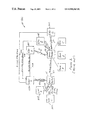
- FIG. 1 is a somewhat simplified network diagram indicating various channels which may be established between network entities to provide electronic bill presentment services.
- the network includes users A–C which are represented on a network by network devices 105 A– 105 C.
- the network devices 105 A– 105 C could, for example be any device capable of communicating over the network, such as a personal computer, palm computer, set top box etc.
- Billers A–C are also represented on the network by network devices 110 A– 110 C, typically although not necessarily high power workstations, mini-computers or mainframe computers, often referred to as servers.
- the network also includes an access portal 115 and a service provider 120 .
- Users A–C access services available on the network by establishing channels 125 A– 125 C with the access portal 115 .
- the access portal is linked to the service provider 120 by channel 130 .
- the service provider in turn is linked to the billers A–C by channels 135 A– 135 C.
- the channels 125 A– 125 C may be Internet channels which are established through an Internet access provider, such as America Online (not shown), using a browser, such as browsers currently available from Microsoft Corporation and Netscape Corporation. Accordingly, the communications between the user devices 105 A– 105 C and the access portal 115 are typically encrypted HTML communication, i.e. HTML/HTTPS.
- Communications between the access portal 115 and the service provider 120 typically will follow a protocol such as IFX, or OFX etc., which may better ensure the security of the communications whether the link is via a private network or a public network such as the Internet.
- a protocol such as IFX, or OFX etc.
- communications between the service provider 120 and the biller network devices 110 A– 110 C will also typically follow an established protocol and be transmitted via channels 135 A– 135 C which are provided on a private or public network.
- Each of the users A–C will typically be known to different network entities by different identifiers. For example, as shown in FIG. 2 , each of the users A–C are known to each of the billers A–C by the user's name, e.g. A, B or C, the applicable user's address, e.g. ZA, ZB or ZC, and a unique account number, e.g. AA–CC which each biller associates with each user.
- the user's name e.g. A, B or C
- the applicable user's address e.g. ZA, ZB or ZC
- a unique account number e.g. AA–CC which each biller associates with each user.
- the access portal 115 will typically know each of the users A–C by a unique user name, e.g. A′–C′ and a unique password, e.g. PA–PC.
- users may be known to the access portal 115 by a digital certificate, e.g. a digital signature, although this is relatively uncommon today.
- the user name and password or digital certificate are often referred to as the user's credentials and are used by the access portal 115 to authenticate the user.
- the access portal 115 then vouches for authenticated users to other network entities. Should a particular user also have a transactional relationship with the access portal, for example if the access portal is a user's financial institute or stock brokerage firm, the user will also typically be known to the access portal by additional information similar to that shown in the biller columns of FIG. 2 .
- FIG. 3A depicts typical communications between and functions of various network entities in providing bill summary information to a requesting user.
- network device 105 A representing user A, implements a browser 305 , typically stored on a local memory, to communicate its credentials via an encrypted HTML communication over the Internet channel 125 A to the access portal 115 .
- the access portal 115 processes the credentials to authenticate user A, as indicated by reference numeral 310 .
- Portal 115 then provides a response, as represented by the communicated authentication message, to network device 105 A either granting or denying access based on whether or not user A has been successfully authenticated by the processing of the credentials. If access is granted, user A, operating network device 105 A, may now request bill summary information from the access portal 115 via the channel 125 A.
- the access portal 115 transmits the request for bill summary information via a protocol over channel 130 to the service provider 120 .
- the service provider 120 retrieves the bill summary information and applicable universal resource locators (URL's) 315 from, for example, a local memory.
- the bill summary information and URL's 315 are typically provided by the billers via protocol or batch transmissions over channels 135 A– 135 C to the server 120 off-line, i.e. in non-real time, with respect to the user request for the bill summary information.
- the bill summary information and URL's are provided over channel 130 from the service provider 120 to the access portal 115 .
- the access portal 115 then directs the bill summary and associated URL's to the user Internet device 105 A via the Internet channel 125 A in an encrypted HTML message.
- bill summary information and URL's flow via a protocol from the biller to the service provider and from the service provider to the access portal.
- the bill summary information is only provided by the access portal to the user after authentication of the user.
- the bill summary information and associated URL's for a particular user are provided to the access portal for transmission to the requesting user only if the access portal can vouch for the user to the service provider based upon its authentication of the user.
- the URL's associated with the bill summary information represent the addresses to the bill detail information stored on the network 100 for the transmitted summarized bill information.
- the bill detail information of billers A–C may be respectively stored, for example, on the memories 320 A– 320 C. It should be recognized that, as described in the above-referenced related applications, the bill detail information could also or alternatively be stored at the service provider 120 or at another network site controlled, for example, by a bill aggregator.
- the URL's to the bill detail information are passed, along with the bill summary information, from the service provider 120 to the access portal 115 and from there to the user network device 105 A.
- each URL is embedded as a hyperlink in the applicable bill summary information presentation which will appear on a display included in the network device 105 A.
- FIG. 4 depicts a display 400 of network device 105 A which is used to present the requested bill summary information for user A.
- the presentation includes the names of billers A–C in display areas 405 A– 405 C, the applicable bill amounts XA–XC billed by each of the billers A–C to user A in display areas 410 A– 410 C, and a view bill request area associated with each of the billers A–C in display areas 415 A– 415 C which can be clicked on using a mouse or other input device to activate the applicable hyperlink URL HA-HC, identified with reference numerals 420 A– 420 C, to establish a link to the bill detail information underlying the bill summary information being presented.
- the applicable bill may also be paid directly from the bill summary presentation by clicking on the appropriate pay bill area 425 A– 425 C.
- the user network device 105 A is linked via an encrypted HTML Internet channel 140 A to the biller address, i.e. URL address HA, at which the detailed bill information of the biller A for user A is stored.
- the detailed bill information is then provided via the channel 140 A to the user A network device 105 A without either the request or the provided detailed bill information flowing through the service provider 120 or access portal 115 .
- the hyperlink would link directly to an address at the aggregator or service provider network site at which the requested detailed bill information is maintained.
- the access portal 115 does not vouch for user A to biller A, the aggregator, or the service provider 120 in connection with the bill detail request and the bill detail information is communicated to the user A from biller A, the aggregator or the service provider 120 without flowing through the access portal 115 .
- the somewhat extended URL 500 includes a network address 505 for the bill detail information, a bill identification (ID) 510 which identifies the particular bill being requested, and a user account number 515 which the biller associates with the applicable user.
- ID bill identification
- user account number the bill ID and user account number are typically encrypted, but may instead be hashed.
- FIG. 5B presents a more realistic depiction of the somewhat extended URL 500 of FIG. 5A for a typical Internet address prior to encrypting or hashing the bill ID 510 and user account number 515 . More particularly, FIG. 5B depicts the somewhat extended URL 500 ′ with the network address 505 ′, the bill ID 510 ′ and the account number 515 ′.
- the somewhat extended URL 500 ′ provides the recipient of the request for detailed bill information, e.g. the biller, bill aggregator or service provider, with sufficient information to identify the particular bill based on the bill ID 510 ′ and to verify the user account number based on account number 515 ′, prior to allowing access to the detailed bill information stored at address 505 ′.
- the recipient has no way of verifying that the request has actually been made by the appropriate user, for example user A as shown in FIG. 3B .
- the recipient there is no way for the recipient to know whether the somewhat extended URL originally transmitted by the access portal 115 has been tampered with and, for example, includes modified e.g. mangled, address, bill ID and/or user account number information.
- the recipient it is impossible for the recipient to know if the somewhat extended URL has been improperly copied from the user's browser either by operation of the user's network device on which the somewhat extended URL may be stored, by hacking into the information stored on the user's network device by the browser, or by installing coding, such as a JAVA applet, which automatically transmits information stored on the user's network device without user's knowledge to a network device under the control of others. It is also impossible for the recipient to know if the encrypted data has been altered. Hence, the proposed implementation of OFX 1.51 cannot ensure the integrity of the somewhat extended URL or serve as an aid in authenticating to the recipient that the requester is who he/she says he/she is.
- a networked system for accessing information includes a first network station, such as a network server or other network device, which represents a first network entity, for example a biller.
- a second network station which could be another network server or some other network device, represents a second network entity, such as an access portal, and controls access to the network by a third network entity.
- the first station controls access to information, such as detailed bill or other information, stored on a network for the third network entity, such as a customer of the biller.
- the first station encrypts a first component message, sometimes simply referred to as a first component of an aggregate message, with a first crypto-key associated with the first network entity, e.g. the biller.
- the first crypto-key could be a symmetric crypto-key which is known only to the first network entity.
- the first crypto-key could be a non-symmetric crypto-key, such as a public crypto-key of a joint private-public crypto-key pair associated with the first network entity.
- the first network station encrypts the first component message off-line, i.e. in non-real time. That is, preferable the first network station encrypts the first component message at a time other than the time of a request, such as a request for bill summary information, which will be responded to by transmitting the encrypted first component message.
- the first component message preferably includes identity information associated with the third network entity, and integrity information which corresponds to the identity information.
- the identity information advantageously includes an identification of information stored on the network, such as a bill ID and/or an account number.
- the integrity information could, for example, include a hash of the identity information.
- the first network station combines the encrypted first component message with a network address for the stored information.
- the integrity information provides enhanced immutability, by ensuring that the first network entity can verify that a returned first component message has not been mangled or otherwise altered. For example, if the first component message includes a bill ID and payor account number which is returned to the biller by the payor with the request for detailed bill information, the biller can use the integrity information to verify that the returned bill ID and account information are the same bill ID and account number included in the first component message.
- the second network station encrypts a second component message with a second crypto-key and combines the encrypted first and the encrypted second component messages.
- the combined messages are then transmitted over the network, which could for example be the Internet. It would be recognized by those skilled in the art that the second crypto-key could, if desired, also be applied to the encrypted first component message at the time of encrypting the second component message.
- the second crypto-key could be a non-symmetric crypto-key.
- the non-symmetric crypto key might, for example, be a private crypto-key of a joint private-public crypto-key pair associated with the second network entity.
- the second crypto-key could be a symmetric crypto-key known also to the first network entity.
- the second network station encrypts the second component message and combines the encrypted first and the encrypted second component messages on-line, i.e. in real time. That is, the second network station beneficially encrypts the second component message and combines it with the encrypted first component message at the time of a request, e.g. a bill summary request, which will be responded to by transmitting the combine component messages.
- the second component message preferably includes voucher information which indicates that the second network entity has authenticated the third network entity.
- the voucher information enhances authentication by allowing the second network entity to vouch for the third network entity to the first network entity.
- the voucher information can be used to authenticate who the third network entity is and, if desired, the third network entity's relationship with the second network entity. This allows, for example, a portal to confirm to a biller that the payor requesting detailed bill information is who he/she says he/she is and that the payor has a relationship with the portal.
- the second component message also includes a timestamp corresponding to a time at which the combined messages are transmitted by the second network station.
- the timestamp enhances secrecy by preventing a misappropriated combined messages from later, i.e. beyond some designated time period after the time indicated by the timestamp, being used to access the information, such as detailed bill information.
- the timestamp also enhances non-repudiation, since it can be used by the first network entity to confirm that the combined messages were recently transmitted by the second network entity to the third network entity.
- the timestamp can be used by a biller to confirm that a request for detailed bill information was received promptly after the associated bill summary information had been provided by a portal to the applicable payor.
- a third network station such as a personal computer or other network device, represents the third network entity and receives the transmitted combined messages, or what might also be referred to as an aggregate message formed of combined component messages.
- the third station further transmits the received combined messages over the network in order to obtain access to the stored information.
- the first network station receives the further transmitted combined messages, and decrypts the encrypted first and the encrypted second component messages contained therein.
- the first network station then controls access by the third network station to the stored information based on the decrypted first and second component messages. For example, if the first station is unable to successfully decrypt either of the component messages, access would typically be denied.
- the decrypted first component message is associated with an entity different than the entity being vouched for in the second component message access would also be denied. If the timestamp indicates that a threshold time period has expired since the second network station transmitted the combined message, access may be denied.
- a fourth network station such as another server or network device, represents a fourth network entity, for example a service provider.
- the fourth network device encrypts a third component message with a third crypto-key and initially combines the encrypted first and third component messages.
- the fourth network station then transmits the initially combined messages over the network.
- the third crypto-key could be a non-symmetric crypto-key, which, for example, might be a private crypto-key of a joint private-public crypto-key pair associated with the fourth network entity.
- the third crypto-key could be a symmetric crypto-key known also to the first network entity.
- the fourth network station encrypts the third component message and combines the encrypted first and the encrypted third component messages on-line, i.e. in real time. That is, the fourth network station advantageously encrypts the third component message and combines it with the first component message at the time of a request, e.g. a bill summary request, which will be responded to by transmitting the combined messages.
- the public crypto-keys associated with the second and fourth network entities could be distributed by either one of these entities, or by each of these entities, or by some other network entity.
- the third component message preferably includes relationship information which indicates that the identity and integrity information was received by the fourth network entity from the first network entity and transmitted by the fourth network entity to the second network entity.
- the second network station receives the transmitted initially combined messages, and combines the encrypted first and the encrypted third component messages contained therein with the encrypted second component message to create the above described combined messages.
- the first network station can decrypt the encrypted third component message and also use this message to control access by the third network station to the stored information. For example, if the information in the third component message is inconsistent with that in the second component message, access will be denied.
- the network could be made up of multiple sub-networks, some of which could be public while others are private.
- the first and third network stations and the second and third network stations might communicate over the Internet, while the fourth network station communicates with the first network station via the Internet or some other network, and with the second network station over the Internet or some still further network.
- an electronic message has a first component created by a first network entity and encrypted with a first crypto-key, associated with the first network entity, such that the encrypted first component can be decrypted by only the first entity.
- the message also includes a second component created by a second network entity, and encrypted with a second crypto-key, such that the encrypted second component can also be decrypted by the first network entity.
- the message may advantageously additionally include a third component created by a third network entity and encrypted with a third crypto-key, associated with the third network entity, such that the encrypted third component can be decrypted by the first network entity.
- an electronic message includes a first component encrypted with only a symmetric crypto-key and a second component, different than the first component, encrypted with only a non-symmetric crypto-key.
- the symmetric crypto-key is associated with a first entity, and may only be known to the first entity, while the non-symmetric crypto-key is associated with a second entity.
- the non-symmetric crypto-key may beneficially be a private crypto-key of a joint private-public crypto-key pair associated with the second entity.
- an extended network universal resource locator which is particularly suitable for Internet commerce includes a first component having a network address at which stored information can be accessed on a network.
- the extended URL also includes a second component having identity information associated with a first network entity and an integrity value corresponding to the identity information.
- the second component is encrypted with a first crypto-key of a second network entity.
- the extended URL additionally includes a third component having relationship information indicating that the encrypted second component was received by a third network entity from the second network entity and transmitted by the third network entity to a fourth network entity.
- the third component is encrypted with a second crypto-key of the third network entity.
- the extended URL further includes a fourth component having voucher information indicating that the fourth network entity has authenticated the first network entity and that transmission of the extended URL by the fourth network entity to the first network entity occurred at a particular time.
- the fourth component is encrypted with a third crypto-key of the fourth network entity.
- the stored information could be detailed bill information.
- the network address would be an Internet URL.
- the identity information could include an identification of the stored information, e.g. detailed bill information and an account number associated with the first network entity.
- the integrity value is a hash of the identity information and the transmission time information is a timestamp.
- the second network entity might be a biller or other entity which controls access to the stored information, such as the detailed bill information.
- the third network entity might be a service provider, such as CheckFree Corporation, which controls access to other information, such a summary bill information, which is transmitted with the extended network universal resource locator by the fourth network entity to the first network entity, which might be the customer.
- the fourth network entity might an access portal which controls access by the first network entity to other entities on the network.
- FIG. 1 depicts a conventional bill presentment network.
- FIG. 2 depicts the user identification information conventionally available to the access portal and the billers of FIG. 1 .
- FIG. 3A depicts a typical message flows between a user, the access portal, the service provider and a biller to request and present bill summary information via the FIG. 1 network.
- FIG. 3B depicts a typical message flows between and a user and a biller to request and present detailed bill information via the FIG. 1 network.
- FIG. 4 depicts a conventional presentation of bill summary information to the user shown in FIG. 3A .
- FIG. 5A depicts a conventional URL for use by the user shown in FIG. 3B in requesting detailed bill information.
- FIG. 5B is a more realistic depiction of the URL of FIG. 5A .
- FIG. 6 depicts message flows between a user, the access portal, the service provider and a biller to request and present bill summary information via the FIG. 1 network in accordance with the present invention.
- FIG. 7 depicts a portion of the collaboratively manufactured extended URL for use in requesting detailed bill information as shown in FIG. 6 , in accordance with the present invention.
- FIG. 8 depicts another portion of the collaboratively manufactured extended URL for use in requesting detailed bill information as shown in FIG. 6 , in accordance with the present invention.
- FIG. 9 depicts a combination of summary bill information and the portions of the collaboratively manufactured extended URL shown in FIGS. 7 and 8 , in accordance with the present invention.
- FIG. 10 depicts still another portion of the collaboratively manufactured extended URL for use in requesting detailed bill information as shown in FIG. 6 , in accordance with the present invention.
- FIG. 11 depicts a combination of summary bill information and the collaboratively manufactured extended URL, in accordance with the present invention.
- the present invention has wide applicability and can be easily adapted for use in obtaining virtually any type of private information by a user directly from the custodian of that information.
- the present invention may have significant application in web banking, web brokerage, web mortgaging, request for credit reports, etc. without requiring the user to sign-on with other than its access portal during the session, even though the user will access the information directly from an entity other that the access portal during the session.
- FIG. 6 depicts typical communications between and functions of various network entities in providing bill summary information to a requesting user with a collaboratively manufactured extended URL.
- network device 105 A representing user A implements a browser 305 to communicate its credentials via an encrypted HTML communication over the Internet channel 125 A to the access portal 115 .
- the access portal 115 processes the credentials to authenticate user A as indicated by reference numeral 310 , and provides a response, as represented by the communicated authentication message, to network device 105 A either granting or denying access based on whether or not User A has been successfully authenticated by the processing of the credentials. If access is granted, user A, operating network device 105 A, can now request bill summary information from the access portal 115 via the channel 125 A.
- the access portal 115 transmits the request via a protocol over channel 130 to the service provider 120 .
- the URL 500 conventionally provided to the service provider 120 from the biller includes a network address (NA) for the bill detail information 505 , a bill ID (BID) 510 which identifies a particular bill being requested and the account number (AN) 515 which the biller associates with the applicable user.
- NA network address
- BID bill ID
- AN account number
- the biller performs a hash computation, H, on the network address (NA) 505 for the bill detail information, the bill ID (BID) 510 which identifies a particular bill being requested and the account number (AN) 515 which the biller associates with the applicable user to form an integrity value (IV) 520 as follows: H[NA+BID+AN] (1)
- the bill ID 510 , user account number 515 and the integrity value 520 are then encrypted using a symmetric encryption key E to form an encrypted message as follows: NA+E [BID+AN+IV] (2)
- the encryption could be performed using the biller's non-symmetric public key of a joint private/public key pair, in lieu of the symmetric key E.
- the encryption and integrity value ensure the integrity of the base data, i.e. the bill ID 510 and the user account number 515 , and the identification of the applicable user, in this case user A.
- the encrypted integrity value provides enhanced protection against altering of the information which will be returned to the biller by the payor with the request for detailed bill information. Hence, the biller can be confident that the exact bill ID, account information and user identification sent to the user is returned with user's the request for detailed bill information.
- the encrypted bill ID 510 , user account number 515 and integrity value 520 are also signed using a digital certificate S(1), preferably supplied by the service provider 120 but which could alternatively be supplied by a separate certificate authority, to form an encrypted, signed extended URL message 700 to the detailed bill information as follows: NA+[E[BID+AN+IV]]S(1) (3)
- the bill summary information (BSI) and the encrypted, signed extended URL message 700 are provided by each biller A–C, preferably via a secure protocol or batch communication over channels 135 A– 135 C, to the service provider 120 in a message 315 ′ as the following: BSI+NA+[E[BID+AN+IV]]S(1) (4)
- the service provider 120 can retrieve, for example from a local memory, the applicable message(s) 315 ′.
- the service provider 120 creates, either prior to, i.e, off-line, or at the time of the request for the bill summary information, i.e. on-line, an encrypted, signed relationship certification (RC) 800 , as shown in FIG. 8 .
- the relationship certificate includes a certification 810 that the service provider 120 received each of the applicable encrypted, signed extended URL messages 700 from the applicable biller A–C and a certification 820 that the service provider 120 is delivering the applicable encrypted, signed extended URL messages 700 to the access portal 115 .
- the access portal 115 may, for example under the OFX protocol, be identified to the service provider 120 in the request for bill summary information received by the service provider 120 from the access portal 115 .
- the relationship certificate is encrypted, using the service provider's 120 non-symmetric private key, PKSP(2), of its joint private key PKSP (2)/public key PUBKSP(2) pair, and digitally signed using the service provider's 120 digital certificate S(2).
- PKSP(2) non-symmetric private key
- PUBKSP(2) public key
- the encrypted, signed relationship certificate will take the form of a message such as the following: [[RC]PKSP(2)]S(2) (5)
- the encrypted relationship certificate will ensure that the commercial parties, i.e. the service provider 120 and the access portal 115 , are identified in the extended URL.
- the bill summary information 910 and a further extended URL message are transmitted over channel 130 from the service provider 120 to the access portal 115 in a further extended message 900 in the following form: BSI+NA+[E[BID+AN+IV]]S(1)+[[RC]PKSP(2)]S(2) (6)
- the message 900 may be created and stored by the service provider 120 prior to receiving a request for the bill summary information or created in response to the receipt of such a request.
- the access portal 115 may, if desired verify that message 900 is from the service provider 120 and intended for the access portal 115 by applying the public key PUBKSP(2) of service provider 120 to the encrypted relationship certificate as follows: [[RC]PKSP(2)]PUBSP(2) (7)
- the access portal 115 continues the collaborative manufacture of the still further extended URL which will ultimately be returned to the user requesting the bill information.
- the access portal 115 creates a voucher (V) 1005 , depicted in FIG. 10 , which identifies the access portal 115 and indicates that the access portal 115 has authenticated the user, in this case user A.
- the access portal 115 then encrypts, using the access portal's 115 non-symmetric private key, PKAP(3), of its joint private key PKAP(3)/public key PUBKAP(3) pair, and signs, using a digital certificate, S(3), provided by the service provider 120 or some other certificate authority, the voucher (V) 1005 and a time stamp (TS) 1010 to form an encrypted, signed voucher record (VR) 1000 as follows: [[V+TS]PKAP(3)]S(3) (8)
- the encrypted, signed voucher will ensure that it can be verified that the applicable user is known to the access portal 115 , and the encrypted, signed timestamp will ensure that the bill detail request has only a limited lifetime.
- the voucher enhances authentication. That is, the voucher, which will be transmitted by the portal to the user with the bill summary information and by the user to the biller with the request for detailed bill information as will be described further below, serves as the portal's confirmation to the biller that the payor is in fact who he/she says he/she is and that the payor has a relationship with the portal.
- the timestamp enhances secrecy and non-repudiation by preventing the network address 505 in the collaboratively manufacture extended URL 1150 from being used to access the user's is detailed bill information after a short timeout, i.e. threshold, period, e.g. 30 minutes from the transmission of the extended URL 1150 by the portal.
- a short timeout i.e. threshold, period, e.g. 30 minutes from the transmission of the extended URL 1150 by the portal.
- the timestamp prevents a misappropriated network address 505 from being used to access detailed bill information after a relatively short period of time, the likelihood that a request to access detailed bill information from some misappropriating party will be granted, is significantly reduced.
- the timestamp evidences that the bill summary information associated with the now requested detailed bill information was recently, i.e. within the timeout period, transmitted to the user by the portal, it is more difficult for the user to repudiate its receipt of the bill summary information and/or of its request for access to the detailed bill information.
- the bill summary information and the still further extended URL 1150 including the encrypted, signed extended URL message 700 , the encrypted, signed relationship certification 800 , and the encrypted, signed voucher record 1000 , are transmitted as the following message, depicted as message 1100 in FIG. 11 , over encrypted html channel 130 , from the access portal 115 to the requesting user, here user A being represented by network device 105 A: BSI+NA+[E[BID+AN+IV]]S(1)+[[RC]PKSP(2)]S(2)+[[VR]PKAP(3)]S(3) (9)
- SSL secure socket layer
- the access portal 115 directs to the user network device 105 A, via the channel 125 A in an encrypted HTML message, a message 1100 having a very rich, collaboratively manufactured extended URL 1150 including:
- the display 400 of Internet device 105 A presents, as shown in FIG. 4 , the requested bill summary for user A.
- the presented bill summary includes a view bill request area associated with each of the billers A–C in display areas 415 A–C.
- the view bill request area can be clicked on using a mouse or other input device to activate the applicable collaboratively manufactured extended URL 1150 forwarded in message 1100 to hyperlink to the bill detail information underlying the applicable bill summary information being presented, as previously described with reference to FIG. 3B .
- the user network device 105 A is linked via an encrypted HTML channel 140 A to the address at which the detailed bill information of the biller A for user A is stored as described with reference to FIG. 3B .
- the biller checks the signature S(1) on the encrypted bill ID 510 , user account number 515 and integrity value 520 , and decrypts, using the corresponding symmetric decryption key D or the billers non-symmetric private key, as applicable, the bill ID 510 , user account number 515 and integrity value 520 as follows: D[BID+AN+IV] (10)
- the biller verifies the decrypted bill ID 510 and user account number 515 and, using the integrity value 520 , also verifies that this information was the same information which it originally forwarded to the service provider 120 .
- the biller checks the signature and then decrypts the encrypted relationship certificate using the public key, PUBKSP(2), of the service provider 120 as follows: [[RC]PKSP(2)]PUBKSP(2) (11)
- the biller using the relationship certificate, verifies that the service provider 120 received the bill ID 510 , user account number 515 and integrity value 520 from the applicable biller and forwarded this information to the access portal 115 .
- the biller checks the signature and then decrypts the encrypted voucher record using the public key, PUBKAP(3) of the access portal 115 as follows: [[VR]PKAP(3)]PUBKAP(3) (12)
- the biller using the voucher record, verifies that the access portal 115 identified in the relationship statement of the service provider 120 vouches for the applicable user, and that, based on the time stamp, the time period within which the request for detailed bill information has been received is within a designated threshold, preferably two to five minutes.
- the bill summary information is not transmitted until after the applicable user is authenticated by the access portal.
- the bill summary information for a particular user is provided to the access portal for transmission to the requesting user only if the access portal 115 can vouch for the user to the service provider 120 based upon its authentication of the user.
- the collaboratively manufactured extended URL 1150 provides the request recipient, e.g. the biller, bill aggregator or service provider etc., information necessary to identify the particular bill and verify the user account number prior to allowing access to the detailed bill information.
- the recipient now has a way of verifying that the request has actually been made by the appropriate user, for example user A as shown in FIG. 6 .
- the collaboratively manufactured extended URL 1150 provides the recipient with the ability to verify that the information originally transmitted by the access portal has not been tampered with and hence, reflects the correct network address, bill ID and user account number information. Further, the collaboratively manufactured extended URL 1150 makes it possible for the recipient to determine if the information has been improperly copied from user A's browser. Hence, by collaborative manufacture the integrity of the information and authenticity of the requesting party can be ensured.
- the present invention addresses the problem of transitive authentication. Further, the present invention provides a technique which protects the integrity of the URL's which are used to access private information over a network. Additionally, the present invention provides a technique which allows a URL to be utilized by a request recipient to authenticate the requesting party.
Abstract
Description
H[NA+BID+AN] (1)
NA+E [BID+AN+IV] (2)
NA+[E[BID+AN+IV]]S(1) (3)
BSI+NA+[E[BID+AN+IV]]S(1) (4)
[[RC]PKSP(2)]S(2) (5)
The encrypted relationship certificate will ensure that the commercial parties, i.e. the
BSI+NA+[E[BID+AN+IV]]S(1)+[[RC]PKSP(2)]S(2) (6)
It should be recognized that the
[[RC]PKSP(2)]PUBSP(2) (7)
[[V+TS]PKAP(3)]S(3) (8)
The encrypted, signed voucher will ensure that it can be verified that the applicable user is known to the
BSI+NA+[E[BID+AN+IV]]S(1)+[[RC]PKSP(2)]S(2)+[[VR]PKAP(3)]S(3) (9)
It will be recognized that encrypted html channels are often referred to as https or secure socket layer (SSL) channels.
-
- (i) the encrypted, signed
extended URL message 700 generated by the biller with the unencrypted network address, NA, 505 at which the bill detail information is stored and the encrypted, signed bill identification, BID, 510, user account number, AN, 515, and integrity value, IV, 520, - (ii) the encrypted, signed relationship certification, RC, 800 generated by the
service provider 120 which certifies that the encrypted signedextended URL message 700 was received from the applicable biller A–C and delivered to theapplicable access portal 115, and - (iii) the encrypted, signed voucher record, VR, 1000 generated by the access portal with the
voucher 1005 certifying that theaccess portal 115 has provided the collaboratively manufacturedextended message 1100 to the applicable user, in this case user A, and thetime stamp 1010.
- (i) the encrypted, signed
D[BID+AN+IV] (10)
[[RC]PKSP(2)]PUBKSP(2) (11)
The biller, using the relationship certificate, verifies that the
[[VR]PKAP(3)]PUBKAP(3) (12)
The biller, using the voucher record, verifies that the
Claims (38)
Priority Applications (10)
| Application Number | Priority Date | Filing Date | Title |
|---|---|---|---|
| US09/471,490 US6948063B1 (en) | 1999-12-23 | 1999-12-23 | Securing electronic transactions over public networks |
| ZA200007489A ZA200007489B (en) | 1999-12-23 | 2000-12-14 | Securing electronic transactions over public networks. |
| NZ508911A NZ508911A (en) | 1999-12-23 | 2000-12-15 | Securing electronic transactions over network stations by using encryption |
| AU72401/00A AU7240100A (en) | 1999-12-23 | 2000-12-20 | Secure electronic transactions over public networks |
| EP00127893A EP1111559A2 (en) | 1999-12-23 | 2000-12-20 | Securing electronic transactions over public networks |
| CA002329492A CA2329492A1 (en) | 1999-12-23 | 2000-12-22 | Securing electronic transactions over public networks |
| JP2000393349A JP2001257671A (en) | 1999-12-23 | 2000-12-25 | Secure electronic trade transaction on public network |
| US11/139,512 US7334128B2 (en) | 1999-12-23 | 2005-05-31 | Accessing information on a network using an extended network universal resource locator |
| US11/479,319 US7426638B2 (en) | 1999-12-23 | 2006-06-30 | Controlling access to information on a network using an extended network universal resource locator |
| US11/493,340 US7415610B2 (en) | 1999-12-23 | 2006-07-26 | Facilitating access to information stored on a network using an extended network universal resource locator |
Applications Claiming Priority (1)
| Application Number | Priority Date | Filing Date | Title |
|---|---|---|---|
| US09/471,490 US6948063B1 (en) | 1999-12-23 | 1999-12-23 | Securing electronic transactions over public networks |
Related Child Applications (1)
| Application Number | Title | Priority Date | Filing Date |
|---|---|---|---|
| US11/139,512 Continuation US7334128B2 (en) | 1999-12-23 | 2005-05-31 | Accessing information on a network using an extended network universal resource locator |
Publications (1)
| Publication Number | Publication Date |
|---|---|
| US6948063B1 true US6948063B1 (en) | 2005-09-20 |
Family
ID=23871818
Family Applications (4)
| Application Number | Title | Priority Date | Filing Date |
|---|---|---|---|
| US09/471,490 Expired - Fee Related US6948063B1 (en) | 1999-12-23 | 1999-12-23 | Securing electronic transactions over public networks |
| US11/139,512 Expired - Fee Related US7334128B2 (en) | 1999-12-23 | 2005-05-31 | Accessing information on a network using an extended network universal resource locator |
| US11/479,319 Expired - Fee Related US7426638B2 (en) | 1999-12-23 | 2006-06-30 | Controlling access to information on a network using an extended network universal resource locator |
| US11/493,340 Expired - Fee Related US7415610B2 (en) | 1999-12-23 | 2006-07-26 | Facilitating access to information stored on a network using an extended network universal resource locator |
Family Applications After (3)
| Application Number | Title | Priority Date | Filing Date |
|---|---|---|---|
| US11/139,512 Expired - Fee Related US7334128B2 (en) | 1999-12-23 | 2005-05-31 | Accessing information on a network using an extended network universal resource locator |
| US11/479,319 Expired - Fee Related US7426638B2 (en) | 1999-12-23 | 2006-06-30 | Controlling access to information on a network using an extended network universal resource locator |
| US11/493,340 Expired - Fee Related US7415610B2 (en) | 1999-12-23 | 2006-07-26 | Facilitating access to information stored on a network using an extended network universal resource locator |
Country Status (7)
| Country | Link |
|---|---|
| US (4) | US6948063B1 (en) |
| EP (1) | EP1111559A2 (en) |
| JP (1) | JP2001257671A (en) |
| AU (1) | AU7240100A (en) |
| CA (1) | CA2329492A1 (en) |
| NZ (1) | NZ508911A (en) |
| ZA (1) | ZA200007489B (en) |
Cited By (63)
| Publication number | Priority date | Publication date | Assignee | Title |
|---|---|---|---|---|
| US20020095567A1 (en) * | 2001-01-12 | 2002-07-18 | Royer Barry Lynn | System and user interface supporting URL processing and concurrent application operation |
| US20020133697A1 (en) * | 2001-01-12 | 2002-09-19 | Royer Barry Lynn | System and user interface for adaptively processing and communicating URL data between applications |
| US20020197979A1 (en) * | 2001-05-22 | 2002-12-26 | Vanderveen Michaela Catalina | Authentication system for mobile entities |
| US20030018808A1 (en) * | 2001-03-26 | 2003-01-23 | Lev Brouk | System and method for mapping of services |
| US20030041178A1 (en) * | 2001-03-26 | 2003-02-27 | Lev Brouk | System and method for routing messages between applications |
| US20030053459A1 (en) * | 2001-03-26 | 2003-03-20 | Lev Brouk | System and method for invocation of services |
| US20040066764A1 (en) * | 2002-10-02 | 2004-04-08 | Nokia Corporation | System and method for resource authorizations during handovers |
| US20050080914A1 (en) * | 2003-10-14 | 2005-04-14 | Grand Central Communications, Inc., A Delaware Corporation | Policy management in an interoperability network |
| US20050086297A1 (en) * | 2003-10-16 | 2005-04-21 | Grand Central Communications, Inc. | Managing virtual business instances within a computer network |
| US20050138210A1 (en) * | 2003-12-19 | 2005-06-23 | Grand Central Communications, Inc. | Apparatus and methods for mediating messages |
| US20050234928A1 (en) * | 2004-03-23 | 2005-10-20 | Grand Central Communications, Inc. | Synchronous interface to asynchronous processes |
| US20060074915A1 (en) * | 2004-10-01 | 2006-04-06 | Grand Central Communications, Inc. | Multiple stakeholders for a single business process |
| US20070033392A1 (en) * | 2005-05-31 | 2007-02-08 | Tricipher, Inc. | Augmented single factor split key asymmetric cryptography-key generation and distributor |
| US20070266238A1 (en) * | 2000-08-08 | 2007-11-15 | Wachovia Corporation | Internet third-party authentication using electronic tickets |
| US20080016242A1 (en) * | 2001-03-30 | 2008-01-17 | Minor Ventures, Llc | Apparatus and methods for managing messages sent between services |
| US20090154703A1 (en) * | 2007-12-18 | 2009-06-18 | Vizio | Content Protection Using Encryption Keys Where only part of the private key is associated with end user data |
| US7590685B2 (en) | 2004-04-07 | 2009-09-15 | Salesforce.Com Inc. | Techniques for providing interoperability as a service |
| US20100017332A1 (en) * | 2001-06-28 | 2010-01-21 | Checkfree Services Corporation | Inter-network financial service |
| US7721328B2 (en) | 2004-10-01 | 2010-05-18 | Salesforce.Com Inc. | Application identity design |
| US7849173B1 (en) * | 2001-12-31 | 2010-12-07 | Christopher Uhlik | System for on-demand access to local area networks |
| US7849498B2 (en) | 2001-01-12 | 2010-12-07 | Siemens Medical Solutions Usa, Inc. | System and user interface supporting context sharing between concurrently operating applications |
| US7930340B2 (en) | 1995-11-13 | 2011-04-19 | Lakshmi Arunachalam | Network transaction portal to control multi-service provider transactions |
| US7979348B2 (en) | 2002-04-23 | 2011-07-12 | Clearing House Payments Co Llc | Payment identification code and payment system using the same |
| US8037158B2 (en) | 1995-11-13 | 2011-10-11 | Lakshmi Arunachalam | Multimedia transactional services |
| US20120011058A1 (en) * | 2001-01-19 | 2012-01-12 | C-Sam, Inc. | Transactional services |
| US8121945B2 (en) | 2006-07-06 | 2012-02-21 | Firethorn Mobile, Inc. | Methods and systems for payment method selection by a payee in a mobile environment |
| US8145568B2 (en) | 2006-07-06 | 2012-03-27 | Firethorn Mobile, Inc. | Methods and systems for indicating a payment in a mobile environment |
| US8160959B2 (en) | 2006-07-06 | 2012-04-17 | Firethorn Mobile, Inc. | Methods and systems for payment transactions in a mobile environment |
| US8271339B2 (en) | 1995-11-13 | 2012-09-18 | Lakshmi Arunachalam | Method and apparatus for enabling real-time bi-directional transactions on a network |
| US8467766B2 (en) | 2006-07-06 | 2013-06-18 | Qualcomm Incorporated | Methods and systems for managing payment sources in a mobile environment |
| US8489067B2 (en) | 2006-07-06 | 2013-07-16 | Qualcomm Incorporated | Methods and systems for distribution of a mobile wallet for a mobile device |
| US8510220B2 (en) | 2006-07-06 | 2013-08-13 | Qualcomm Incorporated | Methods and systems for viewing aggregated payment obligations in a mobile environment |
| US8676672B2 (en) | 2007-08-23 | 2014-03-18 | E2Interactive, Inc. | Systems and methods for electronic delivery of stored value |
| US8725607B2 (en) | 2004-01-30 | 2014-05-13 | The Clearing House Payments Company LLC | Electronic payment clearing and check image exchange systems and methods |
| US8838833B2 (en) | 2004-08-06 | 2014-09-16 | Salesforce.Com, Inc. | Providing on-demand access to services in a wide area network |
| US8874480B2 (en) | 2007-04-27 | 2014-10-28 | Fiserv, Inc. | Centralized payment method and system for online and offline transactions |
| US9064281B2 (en) | 2002-10-31 | 2015-06-23 | Mastercard Mobile Transactions Solutions, Inc. | Multi-panel user interface |
| US20160191522A1 (en) * | 2013-08-02 | 2016-06-30 | Uc Mobile Co., Ltd. | Method and apparatus for accessing website |
| US9454758B2 (en) | 2005-10-06 | 2016-09-27 | Mastercard Mobile Transactions Solutions, Inc. | Configuring a plurality of security isolated wallet containers on a single mobile device |
| US9886691B2 (en) | 2005-10-06 | 2018-02-06 | Mastercard Mobile Transactions Solutions, Inc. | Deploying an issuer-specific widget to a secure wallet container on a client device |
| US9911114B2 (en) | 2006-07-06 | 2018-03-06 | Qualcomm Incorporated | Methods and systems for making a payment via a stored value card in a mobile environment |
| US9948644B2 (en) | 2001-03-26 | 2018-04-17 | Salesforce.Com, Inc. | Routing messages between applications |
| US10068287B2 (en) | 2010-06-11 | 2018-09-04 | David A. Nelsen | Systems and methods to manage and control use of a virtual card |
| US10110591B2 (en) * | 2011-04-01 | 2018-10-23 | Clawd Technologies Inc. | System, method, server and computer-readable medium for real-time verification of a status of a member of an organization |
| US10510055B2 (en) | 2007-10-31 | 2019-12-17 | Mastercard Mobile Transactions Solutions, Inc. | Ensuring secure access by a service provider to one of a plurality of mobile electronic wallets |
| US10937076B2 (en) | 2010-10-13 | 2021-03-02 | E2Interactive, Inc. | Online personalized gifting system |
| US10943432B2 (en) | 2012-09-04 | 2021-03-09 | E2Interactive, Inc. | Processing of a game-playing transaction based on location |
| US10943438B2 (en) | 2012-09-04 | 2021-03-09 | E2Interactive, Inc. | Processing of a game-playing transaction based on location |
| US10954049B2 (en) | 2017-12-12 | 2021-03-23 | E2Interactive, Inc. | Viscous liquid vessel for gifting |
| US11017443B2 (en) | 2014-04-30 | 2021-05-25 | E2Interactive, Inc. | System and method for a merchant onsite personalization gifting platform |
| US11037397B2 (en) | 2012-09-04 | 2021-06-15 | E2Interactive, Inc. | Processing of a user device game-playing transaction based on location |
| US11042853B2 (en) * | 2018-11-29 | 2021-06-22 | Visa International Service Association | System and method for provisioning a gift with a uniform resource locator |
| US11042882B2 (en) | 2015-07-01 | 2021-06-22 | The Clearing House Payments Company, L.L.C. | Real-time payment system, method, apparatus, and computer program |
| US11111065B2 (en) | 2013-02-15 | 2021-09-07 | E2Interactive, Inc. | Gift card presentation devices |
| US11120428B2 (en) | 2013-05-02 | 2021-09-14 | E2Interactive, Inc. | Stored value card kiosk system and method |
| US11182836B2 (en) | 2010-10-13 | 2021-11-23 | E2Interactive, Inc. | Gift card ordering system and method |
| US11219288B2 (en) | 2013-02-15 | 2022-01-11 | E2Interactive, Inc. | Gift card box with slanted tray and slit |
| US11250666B2 (en) | 2013-03-15 | 2022-02-15 | E2Interactive, Inc. | Systems and methods for location-based game play on computing devices |
| US11295308B1 (en) | 2014-10-29 | 2022-04-05 | The Clearing House Payments Company, L.L.C. | Secure payment processing |
| US11436577B2 (en) | 2018-05-03 | 2022-09-06 | The Clearing House Payments Company L.L.C. | Bill pay service with federated directory model support |
| US11436651B2 (en) | 2012-01-30 | 2022-09-06 | E2Interactive, Inc. | Group video generating system |
| US11694168B2 (en) | 2015-07-01 | 2023-07-04 | The Clearing House Payments Company L.L.C. | Real-time payment system, method, apparatus, and computer program |
| US11928696B2 (en) | 2009-12-16 | 2024-03-12 | E2Interactive, Inc. | Systems and methods for generating a virtual value item for a promotional campaign |
Families Citing this family (29)
| Publication number | Priority date | Publication date | Assignee | Title |
|---|---|---|---|---|
| EP1049056A3 (en) | 1999-04-26 | 2001-06-13 | CheckFree Corporation | Electronic bill presentment and/or payment clearinghouse |
| US7080050B1 (en) * | 1999-08-05 | 2006-07-18 | Barter Securities | Electronic bartering system |
| US7734543B2 (en) | 2000-05-09 | 2010-06-08 | Metavante Corporation | Electronic bill presentment and payment system |
| US20080215472A1 (en) * | 2000-06-27 | 2008-09-04 | Nicholas Ahthony Lindsay Brown | Variable use advanced messaging system and method |
| US7293283B2 (en) | 2001-10-16 | 2007-11-06 | Microsoft Corporation | Flexible electronic message security mechanism |
| US7958049B2 (en) | 2001-11-01 | 2011-06-07 | Metavante Corporation | System and method for obtaining customer bill information and facilitating bill payment at biller websites |
| US8799157B1 (en) | 2002-05-08 | 2014-08-05 | Metavante Corporation | Business combined bill management system and method |
| US8751384B2 (en) | 2002-05-08 | 2014-06-10 | Metavante Corporation | Integrated bill presentment and payment system and method of operating the same |
| US20040133513A1 (en) * | 2002-11-01 | 2004-07-08 | Mccoy Randal | Identity protection technique in matching consumers with electronic billers |
| US8073773B2 (en) | 2002-11-01 | 2011-12-06 | Checkfree Corporation | Technique for identifying probable billers of a consumer |
| US7729996B2 (en) * | 2002-11-01 | 2010-06-01 | Checkfree Corporation | Reuse of an EBP account through alternate authentication |
| AU2002368350A1 (en) * | 2002-11-12 | 2004-06-03 | Motorola, Inc. | Method, apparatus and computer program product for processing messages to ensure confidentiality by encrypting the private data of the message |
| US8099762B2 (en) * | 2003-12-02 | 2012-01-17 | Integic Technologies Llc | Secure digital content trading systems and methods |
| US8363835B2 (en) * | 2004-07-21 | 2013-01-29 | Sanyo Electric Co., Ltd. | Method for transmission/reception of contents usage right information in encrypted form, and device thereof |
| US7979417B1 (en) * | 2005-06-30 | 2011-07-12 | Google Inc. | Embedded communication of link information |
| EP1746535A1 (en) * | 2005-07-20 | 2007-01-24 | Lars Olof Kanngard | Secure transaction string |
| GB2449398B (en) * | 2006-09-29 | 2009-02-11 | Imagination Tech Ltd | Improvements in memory management for systems for generating 3-dimensional computer images |
| CA2693340A1 (en) * | 2007-07-31 | 2009-02-05 | Limerick Biopharma, Inc. | Pyrone analog compositions and methods |
| US20090106253A1 (en) * | 2007-10-22 | 2009-04-23 | Ilja Fischer | Portal event verification |
| US20090192911A1 (en) * | 2008-01-29 | 2009-07-30 | Revolution Money Inc. | Payment redirection for online transactions |
| US8397225B2 (en) * | 2008-04-24 | 2013-03-12 | International Business Machines Corporation | Optimizing just-in-time compiling for a java application executing on a compute node |
| US20100180121A1 (en) * | 2009-01-09 | 2010-07-15 | Alcatel-Lucent | Method and apparatus for enhancing security in network-based data communication |
| EP2299652A1 (en) * | 2009-09-21 | 2011-03-23 | Thomson Licensing | Device and method for generating confirmations of data transfers between communication equipments, by data comparison |
| EP2339483A3 (en) * | 2009-11-24 | 2011-09-07 | Sony Corporation | A method for providing/accessing data on the Internet and a respective client, server, and system |
| US20110270760A1 (en) * | 2010-04-30 | 2011-11-03 | Tobsc Inc. | Methods and apparatus for a financial document clearinghouse and secure delivery network |
| US8838982B2 (en) * | 2011-09-21 | 2014-09-16 | Visa International Service Association | Systems and methods to secure user identification |
| US20150100483A1 (en) * | 2013-07-22 | 2015-04-09 | Douglas Schoenberg | Method and system of using smartlinks for constituent/consumer data updating |
| CN106850669B (en) * | 2017-03-03 | 2020-10-23 | 重庆和航科技股份有限公司 | Message security transmission method for Internet of things monitoring system |
| WO2020257657A1 (en) | 2019-06-19 | 2020-12-24 | FinanceNinja, LLC | Systems and methods for implementing a sponsor portal for mediating services to end users |
Citations (8)
| Publication number | Priority date | Publication date | Assignee | Title |
|---|---|---|---|---|
| US5809144A (en) * | 1995-08-24 | 1998-09-15 | Carnegie Mellon University | Method and apparatus for purchasing and delivering digital goods over a network |
| US5815665A (en) * | 1996-04-03 | 1998-09-29 | Microsoft Corporation | System and method for providing trusted brokering services over a distributed network |
| US5987140A (en) * | 1996-04-26 | 1999-11-16 | Verifone, Inc. | System, method and article of manufacture for secure network electronic payment and credit collection |
| US6049786A (en) * | 1997-07-22 | 2000-04-11 | Unisys Corporation | Electronic bill presentment and payment system which deters cheating by employing hashes and digital signatures |
| US6285991B1 (en) * | 1996-12-13 | 2001-09-04 | Visa International Service Association | Secure interactive electronic account statement delivery system |
| US6292789B1 (en) | 1997-08-26 | 2001-09-18 | Citibank, N.A. | Method and system for bill presentment and payment |
| US20020016765A1 (en) | 2000-07-11 | 2002-02-07 | David Sacks | System and method for third-party payment processing |
| US6560581B1 (en) * | 1995-06-29 | 2003-05-06 | Visa International Service Association | System and method for secure electronic commerce transaction |
Family Cites Families (9)
| Publication number | Priority date | Publication date | Assignee | Title |
|---|---|---|---|---|
| JP3199882B2 (en) * | 1993-01-13 | 2001-08-20 | 株式会社東芝 | Nonvolatile semiconductor memory device |
| US5444780A (en) * | 1993-07-22 | 1995-08-22 | International Business Machines Corporation | Client/server based secure timekeeping system |
| US5727065A (en) * | 1994-11-14 | 1998-03-10 | Hughes Electronics | Deferred billing, broadcast, electronic document distribution system and method |
| CA2195968C (en) * | 1995-05-24 | 2001-11-20 | Jay S. Walker | 900 number billing and collection system and method for on-line computer services |
| US6557102B1 (en) * | 1997-09-05 | 2003-04-29 | Koninklijke Philips Electronics N.V. | Digital trust center for medical image authentication |
| US7606355B2 (en) * | 1998-04-22 | 2009-10-20 | Echarge Corporation | Method and apparatus for ordering goods, services and content over an internetwork |
| JP3995338B2 (en) * | 1998-05-27 | 2007-10-24 | 富士通株式会社 | Network connection control method and system |
| JP2000092046A (en) * | 1998-09-11 | 2000-03-31 | Mitsubishi Electric Corp | Remote authentication system |
| US6275934B1 (en) * | 1998-10-16 | 2001-08-14 | Soft Book Press, Inc. | Authentication for information exchange over a communication network |
-
1999
- 1999-12-23 US US09/471,490 patent/US6948063B1/en not_active Expired - Fee Related
-
2000
- 2000-12-14 ZA ZA200007489A patent/ZA200007489B/en unknown
- 2000-12-15 NZ NZ508911A patent/NZ508911A/en not_active IP Right Cessation
- 2000-12-20 AU AU72401/00A patent/AU7240100A/en not_active Abandoned
- 2000-12-20 EP EP00127893A patent/EP1111559A2/en not_active Withdrawn
- 2000-12-22 CA CA002329492A patent/CA2329492A1/en not_active Abandoned
- 2000-12-25 JP JP2000393349A patent/JP2001257671A/en active Pending
-
2005
- 2005-05-31 US US11/139,512 patent/US7334128B2/en not_active Expired - Fee Related
-
2006
- 2006-06-30 US US11/479,319 patent/US7426638B2/en not_active Expired - Fee Related
- 2006-07-26 US US11/493,340 patent/US7415610B2/en not_active Expired - Fee Related
Patent Citations (8)
| Publication number | Priority date | Publication date | Assignee | Title |
|---|---|---|---|---|
| US6560581B1 (en) * | 1995-06-29 | 2003-05-06 | Visa International Service Association | System and method for secure electronic commerce transaction |
| US5809144A (en) * | 1995-08-24 | 1998-09-15 | Carnegie Mellon University | Method and apparatus for purchasing and delivering digital goods over a network |
| US5815665A (en) * | 1996-04-03 | 1998-09-29 | Microsoft Corporation | System and method for providing trusted brokering services over a distributed network |
| US5987140A (en) * | 1996-04-26 | 1999-11-16 | Verifone, Inc. | System, method and article of manufacture for secure network electronic payment and credit collection |
| US6285991B1 (en) * | 1996-12-13 | 2001-09-04 | Visa International Service Association | Secure interactive electronic account statement delivery system |
| US6049786A (en) * | 1997-07-22 | 2000-04-11 | Unisys Corporation | Electronic bill presentment and payment system which deters cheating by employing hashes and digital signatures |
| US6292789B1 (en) | 1997-08-26 | 2001-09-18 | Citibank, N.A. | Method and system for bill presentment and payment |
| US20020016765A1 (en) | 2000-07-11 | 2002-02-07 | David Sacks | System and method for third-party payment processing |
Non-Patent Citations (4)
| Title |
|---|
| Cryptography and Network Security Second Edition. |
| Hush Encryption Engine White Paper Version 2.0 Jul. 2001. |
| Open Financial Exchange Bill Presentment, Jun. 12, 1997, 1997 CheckFree Corp., Intuit Inc., Microsoft Corp, pp. 312-356. |
| Open Financial Exchange Specification 1.5.1, Nov. 23, 1998, pp. 61, 452-453. * |
Cited By (140)
| Publication number | Priority date | Publication date | Assignee | Title |
|---|---|---|---|---|
| US8244833B2 (en) | 1995-11-13 | 2012-08-14 | Lakshmi Arunachalam | Real-time web transaction systems to access on-line services over the web from web applications |
| US8407318B2 (en) | 1995-11-13 | 2013-03-26 | Lakshmi Arunachalam | Managing services on a network |
| US8346894B2 (en) | 1995-11-13 | 2013-01-01 | Lakshmi Arunachalam | Real-time web transactions from web applications |
| US8271339B2 (en) | 1995-11-13 | 2012-09-18 | Lakshmi Arunachalam | Method and apparatus for enabling real-time bi-directional transactions on a network |
| US8108492B2 (en) | 1995-11-13 | 2012-01-31 | Lakshmi Arunachalam | Web application network portal |
| US8037158B2 (en) | 1995-11-13 | 2011-10-11 | Lakshmi Arunachalam | Multimedia transactional services |
| US7930340B2 (en) | 1995-11-13 | 2011-04-19 | Lakshmi Arunachalam | Network transaction portal to control multi-service provider transactions |
| US20070266238A1 (en) * | 2000-08-08 | 2007-11-15 | Wachovia Corporation | Internet third-party authentication using electronic tickets |
| US20020133697A1 (en) * | 2001-01-12 | 2002-09-19 | Royer Barry Lynn | System and user interface for adaptively processing and communicating URL data between applications |
| US20020095567A1 (en) * | 2001-01-12 | 2002-07-18 | Royer Barry Lynn | System and user interface supporting URL processing and concurrent application operation |
| US7127608B2 (en) * | 2001-01-12 | 2006-10-24 | Siemens Medical Solutions Health Services Corporation | System and user interface supporting URL processing and concurrent application operation |
| US7849498B2 (en) | 2001-01-12 | 2010-12-07 | Siemens Medical Solutions Usa, Inc. | System and user interface supporting context sharing between concurrently operating applications |
| US7127609B2 (en) * | 2001-01-12 | 2006-10-24 | Siemens Medical Solutions Health Services Corporation | System and user interface for adaptively processing and communicating URL data between applications |
| US9330389B2 (en) | 2001-01-19 | 2016-05-03 | Mastercard Mobile Transactions Solutions, Inc. | Facilitating establishing trust for conducting direct secure electronic transactions between users and service providers via a mobile wallet |
| US9471914B2 (en) | 2001-01-19 | 2016-10-18 | Mastercard Mobile Transactions Solutions, Inc. | Facilitating a secure transaction over a direct secure transaction channel |
| US8781923B2 (en) | 2001-01-19 | 2014-07-15 | C-Sam, Inc. | Aggregating a user's transactions across a plurality of service institutions |
| US10217102B2 (en) | 2001-01-19 | 2019-02-26 | Mastercard Mobile Transactions Solutions, Inc. | Issuing an account to an electronic transaction device |
| US9070127B2 (en) | 2001-01-19 | 2015-06-30 | Mastercard Mobile Transactions Solutions, Inc. | Administering a plurality of accounts for a client |
| US9177315B2 (en) | 2001-01-19 | 2015-11-03 | Mastercard Mobile Transactions Solutions, Inc. | Establishing direct, secure transaction channels between a device and a plurality of service providers |
| US9208490B2 (en) | 2001-01-19 | 2015-12-08 | Mastercard Mobile Transactions Solutions, Inc. | Facilitating establishing trust for a conducting direct secure electronic transactions between a user and a financial service providers |
| US9330388B2 (en) | 2001-01-19 | 2016-05-03 | Mastercard Mobile Transactions Solutions, Inc. | Facilitating establishing trust for conducting direct secure electronic transactions between a user and airtime service providers |
| US20120011058A1 (en) * | 2001-01-19 | 2012-01-12 | C-Sam, Inc. | Transactional services |
| US9330390B2 (en) | 2001-01-19 | 2016-05-03 | Mastercard Mobile Transactions Solutions, Inc. | Securing a driver license service electronic transaction via a three-dimensional electronic transaction authentication protocol |
| US9870559B2 (en) | 2001-01-19 | 2018-01-16 | Mastercard Mobile Transactions Solutions, Inc. | Establishing direct, secure transaction channels between a device and a plurality of service providers via personalized tokens |
| US9811820B2 (en) | 2001-01-19 | 2017-11-07 | Mastercard Mobile Transactions Solutions, Inc. | Data consolidation expert system for facilitating user control over information use |
| US9697512B2 (en) | 2001-01-19 | 2017-07-04 | Mastercard Mobile Transactions Solutions, Inc. | Facilitating a secure transaction over a direct secure transaction portal |
| US9317849B2 (en) | 2001-01-19 | 2016-04-19 | Mastercard Mobile Transactions Solutions, Inc. | Using confidential information to prepare a request and to suggest offers without revealing confidential information |
| US20030041178A1 (en) * | 2001-03-26 | 2003-02-27 | Lev Brouk | System and method for routing messages between applications |
| US8639843B2 (en) | 2001-03-26 | 2014-01-28 | Salesforce.Com, Inc. | System and method for routing messages between applications |
| US9948644B2 (en) | 2001-03-26 | 2018-04-17 | Salesforce.Com, Inc. | Routing messages between applications |
| US9491126B2 (en) | 2001-03-26 | 2016-11-08 | Salesforce.Com, Inc. | Routing messages between applications |
| US20030018808A1 (en) * | 2001-03-26 | 2003-01-23 | Lev Brouk | System and method for mapping of services |
| US20030053459A1 (en) * | 2001-03-26 | 2003-03-20 | Lev Brouk | System and method for invocation of services |
| US7788399B2 (en) | 2001-03-26 | 2010-08-31 | Salesforce.Com, Inc. | System and method for mapping of services |
| US9467405B2 (en) | 2001-03-26 | 2016-10-11 | Salesforce.Com, Inc. | Routing messages between applications |
| US7689711B2 (en) | 2001-03-26 | 2010-03-30 | Salesforce.Com, Inc. | System and method for routing messages between applications |
| US7516191B2 (en) | 2001-03-26 | 2009-04-07 | Salesforce.Com, Inc. | System and method for invocation of services |
| US9588828B2 (en) | 2001-03-26 | 2017-03-07 | Salesforce.Com, Inc. | System and method for routing messages between applications |
| US20080016242A1 (en) * | 2001-03-30 | 2008-01-17 | Minor Ventures, Llc | Apparatus and methods for managing messages sent between services |
| US9037726B2 (en) | 2001-03-30 | 2015-05-19 | Salesforce.Com, Inc. | Apparatus and methods for managing messages sent between services |
| US11070626B2 (en) | 2001-03-30 | 2021-07-20 | Salesforce.Com, Inc. | Managing messages sent between services |
| US20020197979A1 (en) * | 2001-05-22 | 2002-12-26 | Vanderveen Michaela Catalina | Authentication system for mobile entities |
| US20100017332A1 (en) * | 2001-06-28 | 2010-01-21 | Checkfree Services Corporation | Inter-network financial service |
| US10210488B2 (en) | 2001-06-28 | 2019-02-19 | Checkfree Services Corporation | Inter-network financial service |
| US8620782B2 (en) | 2001-06-28 | 2013-12-31 | Checkfree Services Corporation | Inter-network electronic billing |
| US8595100B2 (en) | 2001-06-28 | 2013-11-26 | Checkfree Services Corporation | Inter-network financial service |
| US9264977B2 (en) | 2001-12-31 | 2016-02-16 | Xylon Llc | System for on-demand access to local area networks |
| US7849173B1 (en) * | 2001-12-31 | 2010-12-07 | Christopher Uhlik | System for on-demand access to local area networks |
| US20110044310A1 (en) * | 2001-12-31 | 2011-02-24 | Durham Logistics Llc | System for on-demand access to local area networks |
| US8521859B2 (en) | 2001-12-31 | 2013-08-27 | Durham Logistics Llc | System for on-demand access to local area networks |
| US7849177B2 (en) | 2001-12-31 | 2010-12-07 | Christopher Uhlik | System for on-demand access to local area networks |
| US7979348B2 (en) | 2002-04-23 | 2011-07-12 | Clearing House Payments Co Llc | Payment identification code and payment system using the same |
| US10387879B2 (en) | 2002-04-23 | 2019-08-20 | The Clearing Housse Payments Company L.L.C. | Payment identification code and payment system using the same |
| US7130286B2 (en) * | 2002-10-02 | 2006-10-31 | Nokia Corporation | System and method for resource authorizations during handovers |
| US20040066764A1 (en) * | 2002-10-02 | 2004-04-08 | Nokia Corporation | System and method for resource authorizations during handovers |
| US9064281B2 (en) | 2002-10-31 | 2015-06-23 | Mastercard Mobile Transactions Solutions, Inc. | Multi-panel user interface |
| US20050080914A1 (en) * | 2003-10-14 | 2005-04-14 | Grand Central Communications, Inc., A Delaware Corporation | Policy management in an interoperability network |
| US9473536B2 (en) | 2003-10-14 | 2016-10-18 | Salesforce.Com, Inc. | Method, system, and computer program product for facilitating communication in an interoperability network |
| US8453196B2 (en) * | 2003-10-14 | 2013-05-28 | Salesforce.Com, Inc. | Policy management in an interoperability network |
| US9338214B2 (en) | 2003-10-16 | 2016-05-10 | Salesforce.Com, Inc. | Managing virtual business instances within a computer network |
| US7904882B2 (en) | 2003-10-16 | 2011-03-08 | Salesforce.Com, Inc. | Managing virtual business instances within a computer network |
| US20050086297A1 (en) * | 2003-10-16 | 2005-04-21 | Grand Central Communications, Inc. | Managing virtual business instances within a computer network |
| US10489730B2 (en) | 2003-10-16 | 2019-11-26 | Salesforce.Com, Inc. | Managing virtual business instances within a computer network |
| US9916549B2 (en) | 2003-10-16 | 2018-03-13 | Salesforce.Com, Inc. | Managing virtual business instances within a computer network |
| US8775654B2 (en) | 2003-12-19 | 2014-07-08 | Salesforce.Com, Inc. | Apparatus and methods for mediating messages |
| US20050138210A1 (en) * | 2003-12-19 | 2005-06-23 | Grand Central Communications, Inc. | Apparatus and methods for mediating messages |
| US8725607B2 (en) | 2004-01-30 | 2014-05-13 | The Clearing House Payments Company LLC | Electronic payment clearing and check image exchange systems and methods |
| US10643190B2 (en) | 2004-01-30 | 2020-05-05 | The Clearing House Payments Company L.L.C. | Electronic payment clearing and check image exchange systems and methods |
| US10636018B2 (en) | 2004-01-30 | 2020-04-28 | The Clearing House Payments Company L.L.C. | Electronic payment clearing and check image exchange systems and methods |
| US10685337B2 (en) | 2004-01-30 | 2020-06-16 | The Clearing House Payments Company L.L.C. | Electronic payment clearing and check image exchange systems and methods |
| US11301824B2 (en) | 2004-01-30 | 2022-04-12 | The Clearing House Payments Company LLC | Electronic payment clearing and check image exchange systems and methods |
| US9799011B2 (en) | 2004-01-30 | 2017-10-24 | The Clearing House Payments Company L.L.C. | Electronic payment clearing and check image exchange systems and methods |
| US9032023B2 (en) | 2004-03-23 | 2015-05-12 | Salesforce.Com, Inc. | Synchronous interface to asynchronous processes |
| US20050234928A1 (en) * | 2004-03-23 | 2005-10-20 | Grand Central Communications, Inc. | Synchronous interface to asynchronous processes |
| US10516700B2 (en) | 2004-03-23 | 2019-12-24 | Salesforce.Com, Inc. | Synchronous interface to asynchronous processes |
| US8260849B2 (en) | 2004-03-23 | 2012-09-04 | Salesforce.Com, Inc. | Synchronous interface to asynchronous processes |
| US7739351B2 (en) | 2004-03-23 | 2010-06-15 | Salesforce.Com, Inc. | Synchronous interface to asynchronous processes |
| US8478818B2 (en) | 2004-03-23 | 2013-07-02 | Salesforce.Com, Inc. | Synchronous interface to asynchronous processes |
| US9674226B2 (en) | 2004-03-23 | 2017-06-06 | Salesforce.Com, Inc. | Synchronous interface to asynchronous processes |
| US7590685B2 (en) | 2004-04-07 | 2009-09-15 | Salesforce.Com Inc. | Techniques for providing interoperability as a service |
| US8838833B2 (en) | 2004-08-06 | 2014-09-16 | Salesforce.Com, Inc. | Providing on-demand access to services in a wide area network |
| US9800586B2 (en) | 2004-10-01 | 2017-10-24 | Salesforce.Com, Inc. | Secure identity federation for non-federated systems |
| US10333941B2 (en) | 2004-10-01 | 2019-06-25 | Salesforce.Com, Inc. | Secure identity federation for non-federated systems |
| US20060074915A1 (en) * | 2004-10-01 | 2006-04-06 | Grand Central Communications, Inc. | Multiple stakeholders for a single business process |
| US9645712B2 (en) | 2004-10-01 | 2017-05-09 | Grand Central Communications, Inc. | Multiple stakeholders for a single business process |
| US20100192204A1 (en) * | 2004-10-01 | 2010-07-29 | Salesforce.Com, Inc. | Application Identity Design |
| US11941230B2 (en) | 2004-10-01 | 2024-03-26 | Salesforce, Inc. | Multiple stakeholders for a single business process |
| US8108919B2 (en) | 2004-10-01 | 2012-01-31 | Salesforce.Com, Inc. | Application identity design |
| US7721328B2 (en) | 2004-10-01 | 2010-05-18 | Salesforce.Com Inc. | Application identity design |
| US9450946B2 (en) | 2004-10-01 | 2016-09-20 | Salesforce.Com, Inc. | Secure identity federation for non-federated systems |
| US11042271B2 (en) | 2004-10-01 | 2021-06-22 | Salesforce.Com, Inc. | Multiple stakeholders for a single business process |
| US7895437B2 (en) * | 2005-05-31 | 2011-02-22 | Vmware, Inc. | Augmented single factor split key asymmetric cryptography-key generation and distributor |
| US20070033392A1 (en) * | 2005-05-31 | 2007-02-08 | Tricipher, Inc. | Augmented single factor split key asymmetric cryptography-key generation and distributor |
| US10026079B2 (en) | 2005-10-06 | 2018-07-17 | Mastercard Mobile Transactions Solutions, Inc. | Selecting ecosystem features for inclusion in operational tiers of a multi-domain ecosystem platform for secure personalized transactions |
| US9626675B2 (en) | 2005-10-06 | 2017-04-18 | Mastercard Mobile Transaction Solutions, Inc. | Updating a widget that was deployed to a secure wallet container on a mobile device |
| US9990625B2 (en) | 2005-10-06 | 2018-06-05 | Mastercard Mobile Transactions Solutions, Inc. | Establishing trust for conducting direct secure electronic transactions between a user and service providers |
| US9454758B2 (en) | 2005-10-06 | 2016-09-27 | Mastercard Mobile Transactions Solutions, Inc. | Configuring a plurality of security isolated wallet containers on a single mobile device |
| US10032160B2 (en) | 2005-10-06 | 2018-07-24 | Mastercard Mobile Transactions Solutions, Inc. | Isolating distinct service provider widgets within a wallet container |
| US10176476B2 (en) | 2005-10-06 | 2019-01-08 | Mastercard Mobile Transactions Solutions, Inc. | Secure ecosystem infrastructure enabling multiple types of electronic wallets in an ecosystem of issuers, service providers, and acquires of instruments |
| US10096025B2 (en) | 2005-10-06 | 2018-10-09 | Mastercard Mobile Transactions Solutions, Inc. | Expert engine tier for adapting transaction-specific user requirements and transaction record handling |
| US9508073B2 (en) | 2005-10-06 | 2016-11-29 | Mastercard Mobile Transactions Solutions, Inc. | Shareable widget interface to mobile wallet functions |
| US10121139B2 (en) | 2005-10-06 | 2018-11-06 | Mastercard Mobile Transactions Solutions, Inc. | Direct user to ticketing service provider secure transaction channel |
| US10140606B2 (en) | 2005-10-06 | 2018-11-27 | Mastercard Mobile Transactions Solutions, Inc. | Direct personal mobile device user to service provider secure transaction channel |
| US9886691B2 (en) | 2005-10-06 | 2018-02-06 | Mastercard Mobile Transactions Solutions, Inc. | Deploying an issuer-specific widget to a secure wallet container on a client device |
| US8145568B2 (en) | 2006-07-06 | 2012-03-27 | Firethorn Mobile, Inc. | Methods and systems for indicating a payment in a mobile environment |
| US8160959B2 (en) | 2006-07-06 | 2012-04-17 | Firethorn Mobile, Inc. | Methods and systems for payment transactions in a mobile environment |
| US8467766B2 (en) | 2006-07-06 | 2013-06-18 | Qualcomm Incorporated | Methods and systems for managing payment sources in a mobile environment |
| US8489067B2 (en) | 2006-07-06 | 2013-07-16 | Qualcomm Incorporated | Methods and systems for distribution of a mobile wallet for a mobile device |
| US9911114B2 (en) | 2006-07-06 | 2018-03-06 | Qualcomm Incorporated | Methods and systems for making a payment via a stored value card in a mobile environment |
| US8510220B2 (en) | 2006-07-06 | 2013-08-13 | Qualcomm Incorporated | Methods and systems for viewing aggregated payment obligations in a mobile environment |
| US8121945B2 (en) | 2006-07-06 | 2012-02-21 | Firethorn Mobile, Inc. | Methods and systems for payment method selection by a payee in a mobile environment |
| US8874480B2 (en) | 2007-04-27 | 2014-10-28 | Fiserv, Inc. | Centralized payment method and system for online and offline transactions |
| US8676672B2 (en) | 2007-08-23 | 2014-03-18 | E2Interactive, Inc. | Systems and methods for electronic delivery of stored value |
| US10510055B2 (en) | 2007-10-31 | 2019-12-17 | Mastercard Mobile Transactions Solutions, Inc. | Ensuring secure access by a service provider to one of a plurality of mobile electronic wallets |
| US20090154703A1 (en) * | 2007-12-18 | 2009-06-18 | Vizio | Content Protection Using Encryption Keys Where only part of the private key is associated with end user data |
| US11928696B2 (en) | 2009-12-16 | 2024-03-12 | E2Interactive, Inc. | Systems and methods for generating a virtual value item for a promotional campaign |
| US10068287B2 (en) | 2010-06-11 | 2018-09-04 | David A. Nelsen | Systems and methods to manage and control use of a virtual card |
| US10937076B2 (en) | 2010-10-13 | 2021-03-02 | E2Interactive, Inc. | Online personalized gifting system |
| US11182836B2 (en) | 2010-10-13 | 2021-11-23 | E2Interactive, Inc. | Gift card ordering system and method |
| US10110591B2 (en) * | 2011-04-01 | 2018-10-23 | Clawd Technologies Inc. | System, method, server and computer-readable medium for real-time verification of a status of a member of an organization |
| US11436651B2 (en) | 2012-01-30 | 2022-09-06 | E2Interactive, Inc. | Group video generating system |
| US10943432B2 (en) | 2012-09-04 | 2021-03-09 | E2Interactive, Inc. | Processing of a game-playing transaction based on location |
| US10943438B2 (en) | 2012-09-04 | 2021-03-09 | E2Interactive, Inc. | Processing of a game-playing transaction based on location |
| US11037397B2 (en) | 2012-09-04 | 2021-06-15 | E2Interactive, Inc. | Processing of a user device game-playing transaction based on location |
| US11219288B2 (en) | 2013-02-15 | 2022-01-11 | E2Interactive, Inc. | Gift card box with slanted tray and slit |
| US11111065B2 (en) | 2013-02-15 | 2021-09-07 | E2Interactive, Inc. | Gift card presentation devices |
| US11250666B2 (en) | 2013-03-15 | 2022-02-15 | E2Interactive, Inc. | Systems and methods for location-based game play on computing devices |
| US11120428B2 (en) | 2013-05-02 | 2021-09-14 | E2Interactive, Inc. | Stored value card kiosk system and method |
| US10778680B2 (en) * | 2013-08-02 | 2020-09-15 | Alibaba Group Holding Limited | Method and apparatus for accessing website |
| US20160191522A1 (en) * | 2013-08-02 | 2016-06-30 | Uc Mobile Co., Ltd. | Method and apparatus for accessing website |
| US11128621B2 (en) | 2013-08-02 | 2021-09-21 | Alibaba Group Holdings Limited | Method and apparatus for accessing website |
| US11017443B2 (en) | 2014-04-30 | 2021-05-25 | E2Interactive, Inc. | System and method for a merchant onsite personalization gifting platform |
| US11295308B1 (en) | 2014-10-29 | 2022-04-05 | The Clearing House Payments Company, L.L.C. | Secure payment processing |
| US11816666B2 (en) | 2014-10-29 | 2023-11-14 | The Clearing House Payments Company L.L.C. | Secure payment processing |
| US11042882B2 (en) | 2015-07-01 | 2021-06-22 | The Clearing House Payments Company, L.L.C. | Real-time payment system, method, apparatus, and computer program |
| US11694168B2 (en) | 2015-07-01 | 2023-07-04 | The Clearing House Payments Company L.L.C. | Real-time payment system, method, apparatus, and computer program |
| US10954049B2 (en) | 2017-12-12 | 2021-03-23 | E2Interactive, Inc. | Viscous liquid vessel for gifting |
| US11436577B2 (en) | 2018-05-03 | 2022-09-06 | The Clearing House Payments Company L.L.C. | Bill pay service with federated directory model support |
| US11829967B2 (en) | 2018-05-03 | 2023-11-28 | The Clearing House Payments Company L.L.C. | Bill pay service with federated directory model support |
| US11042853B2 (en) * | 2018-11-29 | 2021-06-22 | Visa International Service Association | System and method for provisioning a gift with a uniform resource locator |
Also Published As
| Publication number | Publication date |
|---|---|
| US7426638B2 (en) | 2008-09-16 |
| ZA200007489B (en) | 2001-05-15 |
| US20070022052A1 (en) | 2007-01-25 |
| US20050222953A1 (en) | 2005-10-06 |
| US7415610B2 (en) | 2008-08-19 |
| AU7240100A (en) | 2001-06-28 |
| EP1111559A2 (en) | 2001-06-27 |
| CA2329492A1 (en) | 2001-06-23 |
| JP2001257671A (en) | 2001-09-21 |
| US20070016525A1 (en) | 2007-01-18 |
| US7334128B2 (en) | 2008-02-19 |
| NZ508911A (en) | 2002-04-26 |
Similar Documents
| Publication | Publication Date | Title |
|---|---|---|
| US6948063B1 (en) | Securing electronic transactions over public networks | |
| US6105131A (en) | Secure server and method of operation for a distributed information system | |
| US7747856B2 (en) | Session ticket authentication scheme | |
| US6711679B1 (en) | Public key infrastructure delegation | |
| US6539093B1 (en) | Key ring organizer for an electronic business using public key infrastructure | |
| US6957334B1 (en) | Method and system for secure guaranteed transactions over a computer network | |
| US5978918A (en) | Security process for public networks | |
| US7925878B2 (en) | System and method for creating a trusted network capable of facilitating secure open network transactions using batch credentials | |
| CA2280869C (en) | System for providing secure remote command execution network | |
| US6105012A (en) | Security system and method for financial institution server and client web browser | |
| US6430688B1 (en) | Architecture for web-based on-line-off-line digital certificate authority | |
| US7853782B1 (en) | Secure intermediation system and method | |
| US7320073B2 (en) | Secure method for roaming keys and certificates | |
| US20040030887A1 (en) | System and method for providing secure communications between clients and service providers | |
| US20020002678A1 (en) | Internet authentication technology | |
| US20030105955A1 (en) | Secure communication system and method of operation for conducting electronic commerce using remote vault agents interacting with a vault controller | |
| US20010042051A1 (en) | Network transaction system for minimizing software requirements on client computers | |
| US20080022085A1 (en) | Server-client computer network system for carrying out cryptographic operations, and method of carrying out cryptographic operations in such a computer network system | |
| Neuman | Security, payment, and privacy for network commerce | |
| Bhiogade | Secure socket layer | |
| EP1452938A1 (en) | System and method employed to enable a user to securely validate that an internet retail site satisfies pre-determined conditions | |
| US8615787B2 (en) | Secure internet transaction method and apparatus | |
| KR100926153B1 (en) | System For Wireless Public Certification Service Using Electronic Signature With Mobile Terminal and Method For Providing said Service | |
| US6795920B1 (en) | Vault controller secure depositor for managing secure communication | |
| US9172679B1 (en) | Secure intermediation system and method |
Legal Events
| Date | Code | Title | Description |
|---|---|---|---|
| AS | Assignment |
Owner name: CHECKFREE CORPORATION, GEORGIA Free format text: ASSIGNMENT OF ASSIGNORS INTEREST;ASSIGNORS:GANESAN, RAVI;HOGDAY, KENNETH;LEWIS, MATT;REEL/FRAME:010671/0229;SIGNING DATES FROM 20000320 TO 20000327 |
|
| AS | Assignment |
Owner name: CHECKFREE CORPORATION, GEORGIA Free format text: ASSIGNMENT OF ASSIGNORS INTEREST;ASSIGNOR:CHRISTIANSON II, ALFRED L.;REEL/FRAME:011808/0976 Effective date: 20010303 |
|
| CC | Certificate of correction | ||
| FPAY | Fee payment |
Year of fee payment: 4 |
|
| FPAY | Fee payment |
Year of fee payment: 8 |
|
| REMI | Maintenance fee reminder mailed | ||
| LAPS | Lapse for failure to pay maintenance fees |
Free format text: PATENT EXPIRED FOR FAILURE TO PAY MAINTENANCE FEES (ORIGINAL EVENT CODE: EXP.) |
|
| STCH | Information on status: patent discontinuation |
Free format text: PATENT EXPIRED DUE TO NONPAYMENT OF MAINTENANCE FEES UNDER 37 CFR 1.362 |
|
| FP | Lapsed due to failure to pay maintenance fee |
Effective date: 20170920 |