US6950967B1 - Method and apparatus for manufacture test processing a disk drive installed in a computer system - Google Patents
Method and apparatus for manufacture test processing a disk drive installed in a computer system Download PDFInfo
- Publication number
- US6950967B1 US6950967B1 US09/965,595 US96559501A US6950967B1 US 6950967 B1 US6950967 B1 US 6950967B1 US 96559501 A US96559501 A US 96559501A US 6950967 B1 US6950967 B1 US 6950967B1
- Authority
- US
- United States
- Prior art keywords
- lbas
- disk drive
- disk
- processed
- computer system
- Prior art date
- Legal status (The legal status is an assumption and is not a legal conclusion. Google has not performed a legal analysis and makes no representation as to the accuracy of the status listed.)
- Expired - Lifetime, expires
Links
Images


Classifications
-
- G—PHYSICS
- G06—COMPUTING; CALCULATING OR COUNTING
- G06F—ELECTRIC DIGITAL DATA PROCESSING
- G06F11/00—Error detection; Error correction; Monitoring
- G06F11/22—Detection or location of defective computer hardware by testing during standby operation or during idle time, e.g. start-up testing
- G06F11/2205—Detection or location of defective computer hardware by testing during standby operation or during idle time, e.g. start-up testing using arrangements specific to the hardware being tested
- G06F11/2221—Detection or location of defective computer hardware by testing during standby operation or during idle time, e.g. start-up testing using arrangements specific to the hardware being tested to test input/output devices or peripheral units
Definitions
- the invention relates to a method and apparatus for performing manufacture test processing for a disk drive.
- Hard disk drives typically include a magnetic disk that stores a large amount of binary information. This magnetic disk is typically coupled to a hub that is rotated by an electric motor commonly referred to as a spin motor.
- a head In order to write information to and read information from the disk, a head is employed which magnetizes and senses the magnetic field of the disk.
- the head is commonly referred to as a transducer.
- the head is typically located at the end of a cantilevered actuator arm that pivots about a bearing assembly mounted on a base plate.
- the actuator arm has a coil which cooperates with a magnet mounted on the base plate. Providing current to the coil creates torque on the actuator arm and moves the head relative to the disk.
- the coil and magnet are commonly referred to as a voice coil motor.
- the disk drive contains integrated circuits that control the operation of the drive.
- the circuits typically include a read/write channel that is coupled to the head and an interface controller.
- the interface controller is coupled to the host computer and a random access memory (RAM) buffer to store data transferred between the disk and the host computer.
- RAM random access memory
- Data is recorded on the disk in the form of magnetic transitions spaced closely together.
- recording densities both in terms of tracks per inch and linear density along a track have reached a level which creates extreme sensitivity to imperfections in the disk. These imperfections are known as media defects and occur in the magnetic recording layer of the disk.
- Media defects cause portions of the magnetic recording layer to be unacceptable for recording the magnetic transitions.
- Media defects can be small, affecting only a small number of transitions on a small number of tracks, or large, affecting many transitions across multiple tracks.
- Manufacturing tests processes are performed on the disk drive at the factory prior to its installation in a computer system. These tests include flaw mapping, embedded runout compensation (ERC) and final drive verification.
- EEC embedded runout compensation
- Flaw mapping performs a write/verify process over the tracks to identify logical block addresses (LBAs) which possess defects and may not be able to receive and store information.
- LBAs logical block addresses
- the locations of LBAs with defects are stored in a flaw map.
- ERC corrects irregularities in the shape of the tracks (cylinders).
- An error value is generated which indicates the distance between the head and the center of the track at a particular location on the track. The error value provides alignment correction for the head during the read/write process for a particular track on the disk.
- Final drive verification is a follow-up to flaw mapping that confirms that the LBAs do not contain flaws.
- the present invention teaches that manufacturing test processes can be automatically performed by the disk drive once it is activated and operational in a computer system rather than in the factory prior to installation of the disk drive.
- the present invention performs automated manufacture test processes on a disk drive once the disk drive is installed and operating within a computer system.
- the invention includes a processing module located in a memory of the disk drive, and the memory can be a processed portion of the disk, a random access memory (RAM), a read only memory (ROM), as well as any combination of these devices.
- the processing module includes sequences to perform automated tests. The test procedures and other saved information are retrievable by a processor of the disk drive such that the testing is performed at predetermined times.
- the test includes at least one of flaw mapping, embedded runout compensation (ERC) and final drive verification.
- Flaw mapping includes initiating write/verify tests of LBAs on the disk either during normal write commands for the disk drive or when the computer system is idle. Flaw mapping makes an initial query as to whether any user commands are pending. If a write command is pending, an analysis determines whether the addresses to which the information is to be written are LBAs which have been previously processed. If not, during the write function to these LBAs a verify determines whether the information was stored correctly. If the information was not stored correctly, the LBA is reassigned to a processed area of the disk and a pointer provided at the original location to direct all future read and write functions to the new location.
- ERC embedded runout compensation
- the processing module also performs a write function in an area which includes both processed and unprocessed LBAs.
- the processing module performs write functions to processed areas and then perform write/verifies on the unprocessed area before the information is permanently written to a particular LBA.
- the processor When there are no user commands pending and the computer system is idle, the processor performs the write/verify tests on LBAs using test information. As an initial step, information is retrieved from memory which indicates which of the LBAs have been tested and which have not. Once the next unprocessed LBAs are identified, the write/verify functions are performed and all LBAs which have flaws are reassigned to a processed area of the disk and pointers are provided at the previous location. Once a particular increment of the LBAs is processed, a pointer is updated and a check made as to whether any user commands are pending.
- a further test is embedded runout compensation (ERC).
- ERC embedded runout compensation
- the ERC typically is not performed when a user command is being performed or pending. Instead, the ERC is performed during idle times and an error signal is generated which is stored in memory and provides a correction for the head.
- An initial query also asks whether a user command is currently pending. If a user command is pending, it is performed and the ERC test is not performed until idle time. If idle time is detected, a counter is accessed from memory to identify which of the cylinders is processed next. To track the completion of the ERC, counters indicate which cylinders have been tested and which have not. Further, various cylinders are not employed during normal operation of the disk drive until an adjacent cylinder has also been tested. Separate pointers track both of these items.
- the ERC for that cylinder is performed and an error signal is generated and stored in memory. Further, the counters that track which cylinders have been processed are updated and stored in memory. Another query then asks whether there are any user commands pending. If there are, those commands are performed, if not, another cylinder is tested until all unprocessed cylinders are processed.
- Final drive verification ensures that the LBAs which were tested are not flawed. As with the flaw mapping test described above, this test is automatically initiated either during idle time or performed with write functions as part of user commands. If the final drive verification is performed as part of a user command, previously saved counter information is accessed to determine whether the final drive verification has been performed previously on any of the LBAs to which a write is to occur. If not, the write function is performed on the LBAs and the information is verified. If any errors are detected, the LBAs are reassigned and a pointer is generated to direct all future write functions to the reassigned LBAs. Once the write function is complete, the necessary pointers are updated and a further query asks whether any user commands are pending.
- portions of the test described above are performed at the factory prior to the disk drive being installed in the computer system in order to detect any major flaws in the disk. For example, a certain percentage of the LBAs and cylinders at designated locations on the disk are tested to identify any major flaws which extend across multiple LBAs or cylinders.
- FIG. 1 is a top view of a magnetic disk and an actuator arm in a disk drive.
- FIG. 2 is an electronic system diagram of the disk drive.
- FIG. 3 is a flow chart of the steps performed for a write/verify function during flaw mapping of a disk drive.
- FIGS. 4A and 4B are a flow chart of the steps performed by the disk drive during automated flaw mapping.
- FIG. 5 is a flow chart of the steps performed by the disk drive during automated ERC testing.
- FIG. 6 is a flow chart of the steps performed by the disk drive during automated final drive verification.
- FIG. 1 shows hard disk drive 10 in accordance with the present invention.
- Disk drive 10 includes magnetic disk 12 , actuator arm 14 , read/write head 16 , voice coil motor 18 and spin motor 20 .
- Disk 12 is constructed from metal, glass, ceramic or a composite substrate that is covered with a magnetic coating as is known in the art.
- Disk 12 is rotated by spin motor 20 .
- Disk 12 rotates relative to actuator arm 14 which supports head (or heads) 16 .
- Head 16 contains a coil (not shown) which can magnetize and sense the magnetic field of the corresponding adjacent surface of disk 12 .
- voice coil motor 18 At the opposite end of actuator arm 14 from head 16 is voice coil motor 18 .
- Voice coil motor 18 rotates actuator arm 14 and head 16 such that head 16 is positioned to read or write information on disk 12 .
- Disk 12 can have various diameters such as 1.8 inch, 2.5 inch, 3.5 inch, etc.
- the system will typically store data on a 130 tracks per disk surface.
- each track contains servo sectors and each sector is capable of storing up to 768 bytes of data.
- the total assembly is capable of storing up to 130M of data.
- FIG. 2 is a schematic of the electronic system architecture of disk drive 10 .
- the system includes data manager 22 , controller 24 , servo 26 , read only memory (ROM) 28 , read/write (R/W) chip 30 and preamp 32 .
- Data manager 22 provides data exchange between disk drive 10 and host computer 34 .
- Controller 24 provides control signals for various electrical components of disk drive 10 . For instance, controller 24 is connected to servo 26 which controls the operation of voice coil motor 18 and spin motor 20 . Controller 24 is also connected to ROM 28 which stores software that runs disk drive 10 .
- R/W chip 30 controls the read/write functions for data stored on and received from the disk 12 through head 16 and preamp 32 .
- disk drive 10 is installed in host computer 34 .
- Disk drive 10 receives a request from host computer 34 for reading or writing data on disk 12 .
- Data manager 22 receives the request from host computer 34 in the form of logical block addresses (LBAs). This information is provided to controller 24 which in turn converts the logical block addresses to physical disk addresses. Controller 24 then initiates a seek routine through servo 26 , which in turn moves head 16 to the proper location on disk 12 .
- controller 24 provides a z-sector signal to data manager 22 .
- the read or write function is initiated and the necessary functions performed using head 16 , R/W chip 30 and preamp 32 .
- the data extracted by R/W chip 30 is provided through data manager 22 to host computer 34 .
- disk drive 10 operates in host computer 34 substantially as described above, a number of manufacturing tests processes are performed on disk drive 10 .
- the manufacturing test processes are performed at the factory prior to installation of disk drive 10 in host computer 34 .
- other manufacturing tests can be performed while disk drive 10 is installed and operating within host computer 34 .
- Disk drive 10 is equipped with the functionality to perform a number of automated self test procedures.
- the self test procedures include flaw mapping, embedded runout compensation (ERC) and final drive verification.
- EEC embedded runout compensation
- disk drive 10 manufacturing tests such as drive functionality and data optimization are performed at the factory. Additionally, flaw mapping, ERC and final drive verification are performed over a limited area of disk 12 to assure there are no major flaws in disk 12 . Therefore, a portion of disk 12 is processed and ready to store data once host computer 34 is operational. For example, at the factory, flaw mapping and ERC are performed for the first 10 percent of the LBAs. Disk drive 10 is then flaw mapped and ERC is performed for every N tracks of the remaining disk surface to assure there are no very large defects and predict the total number of defects. A processed pointer is then initialized and stored on disk 12 indicating the portions of disk 12 that have been already processed. Also during the factory manufacturing, an automated test program described below is written into the memory of disk drive 10 . The memory can be a processed portion of disk drive 10 , a random access memory (RAM), a read only memory (ROM), and any combination of these devices.
- RAM random access memory
- ROM read only memory
- disk drive 10 is installed in host computer 34 .
- the unprocessed portions of disk 12 are then automatically processed during normal operation of host computer 34 .
- this automated processing occurs during write functions to unprocessed areas of disk 12 and during disk drive idle time (no user commands pending).
- This testing is substantially interruptible and does not significantly reduce the performance of the disk drive 10 during user commands for read and write functions during normal operation.
- tests performed during normal operation of host computer 34 include flaw mapping, ERC and final drive verification.
- flaw mapping and final drive verification write or read/verify tests are performed which determine whether a particular LBA is able receive data when written to.
- FIG. 3 is a flow chart of steps performed during a write/verify test which is employed by the automated test procedures described below.
- a list of LBAs to be analyzed is identified.
- the first LBA in the list is identified and the test procedure begins with test information being written to the LBA.
- the LBA is then read and the information read from the LBA is compared against the test information.
- a determination is then made as to whether the read information is identical to the test information. If any differences in the information read from the LBA are detected, a determination is made that the particular LBA is flawed. If so, the LBA is reassigned to another area on disk 12 and a pointer is placed on disk 12 indicating the new location for the LBA.
- the LBA is determined to be functional and the flaw map is updated for disk 12 . At this point the next LBA in the particular increment is tested, and the flaw mapping continues until all LBAs in the particular increment are tested.
- the flaw mapping process described above is employed as part of the automated flaw mapping procedure for disk drive 10 .
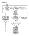
- FIGS. 4A and 4B are a flow chart of the steps performed by the automated flaw mapping process once disk drive 10 is installed in host computer 34 and host computer 34 is operational.
- the processor of disk drive 10 issues an instruction to execute a software program, which is either stored on disk 12 or in ROM, to perform the automated tests. Once this software program is loaded and running, the system is ready to initiate the automated self test.
- a query asks whether a user command is currently pending.
- User commands are instructions which direct disk drive 10 to read or write information on disk 12 . If a user command is pending, a determination is made as to whether it is a read or write command.
- disk drive 10 operations proceed normally. If a read command is detected, disk drive 10 operations proceed normally. If a write command is detected, the process determines whether the LBAs to which the information is to be written are in a processed or unprocessed area of disk 12 . When disk 12 is delivered from the factory, certain areas of disk 12 are already flaw mapped and this is recorded on a flaw map for disk drive 10 which is accessible in memory. Further, as different areas of disk 12 are processed through the flaw mapping process, this is indicated in the flaw map.
- disk drive 10 performs a write of the information and then a verify of what has been written. If the write/verify step fails, a reassignment of the LBAs which failed is performed, the information is written to a processed area of disk 12 , and a pointer is placed on disk 12 which identifies the location of the reassigned LBAs. The pointer also indicates that the flawed area of disk 12 should not be used.
- a write is initially performed to the processed area.
- the write/verify test is performed for the LBAs included therein. If the verify fails, there is a reassignment of the LBAs to new locations on disk 12 and a pointer is provided which redirects all future reads and writes to the new LBAs.
- a determination is made that the write is being performed to an area which has been processed. In this case, there is no need to perform an automated test and the write function is performed normally.
- counters are incorporated in the automated test program.
- One counter is the process LBA counter which indicates the last LBA which was processed.
- the counters are continually updated in case of interruptions due to user commands or power loss.
- the system performs the automated tests until the entire disk 12 is analyzed. As such, the automated program tests areas of disk drive 12 during detected idle times.
- the automated self test disclosed in FIG. 4B is then initiated. Initially, a counter saved in memory is accessed to determine the last increment of LBAs to be processed and identify the next increment of LBAs to be processed. The number of LBAs included in an increment is limited so as not to take enough time to unduly interfere with normal operation of host computer 34 . During the time the automated process is performed, disk drive 10 is inaccessible.
- an additional query asks whether there are enough LBAs left to be processed for a normal processing increment. If there enough LBAs for an increment, the test information is retrieved and employed in a write/verify step for each LBA. Any LBAs which fail the write/verify test are reassigned and a pointer is provided on disk 12 . Once all the LBAs in an increment are tested, the defect map stored in memory is updated, and likewise, the counter which indicates which LBAs have been processed is updated. Another increment of LBAs will be identified and tested unless a new user command is detected or there are no more unprocessed LBAs left.
- the remaining unprocessed LBAs are automatically tested and the defect map is updated and the number of good LBAs are identified.
- the LBAs tested are moved from unprocessed space to processed space.
- the testing program is then updated to indicate that the flaw mapping test is complete.
- FIG. 5 is a flow chart of the steps performed by the automated system when performing ERC.
- a first step (not shown) is the downloading and execution of a program which is either stored in ROM or on a processed area of disk 12 .
- a first query made in the automated test procedure asks whether a user command is pending for reading or writing information on disk 12 . If a user command is pending, the system will discontinue performing the automated test functions and perform the requested user commands. After the command is complete, and the system returns to idle mode the query is made again.
- a first query asks whether there are any unprocessed tracks (cylinders) left to be tested.
- the disk space is broken into three areas.
- the first (lower) is the process area which includes user LBAs.
- the second (middle) in the unprocessed area which does not contain user LBAs.
- the third (top) is the unprocessed area which also contains user LBAs.
- the ERC is executed from the lower to higher areas until all processing is complete. Since the ERC modifies (straightens) the path of the head, user data will not be moved to the process cylinder until the cylinder being tested (target) and target +1 cylinders have been processed. In order to perform the testing, counters are employed.
- the last process user's cylinder indicates the last cylinder which has been processed which is available for storing data.
- the disk drive is configured at the factory such that the last processed user cylinder equals ⁇ 1 and the last process cylinder also equals ⁇ 1.
- the last processed cylinder pointer is accessed to determine which cylinder is next to be processed. Once the next cylinder to be processed is identified, the ERC is performed and the error information for that particular cylinder is stored in memory. After this information is generated the various pointers employed are also updated. For example, the last processed cylinder is incremented up one as is the last processed user cylinder. This information is then saved in memory. The process then returns to start and if no user commands are pending the next unprocessed cylinder is processed.
- FIGS. 6A and 6B are a flowchart of the steps performed in final drive verification.
- a query asks whether a user command is pending. If there is a user command pending, the process determines whether it is a read or write command. If it is a read command, the read function is performed without interruption and the automated program returns to its initial query. If it is a write command, yet another query asks whether the write is to a processed or unprocessed area (with regards to the final drive verification test). If the write command is to an area which has been processed, the write function is performed without interruption and the program returns to its initial query.
- a query then asks whether the area to which the write command is to be carried out includes any unprocessed LBAs.
- a query asks whether all the writes are to an unprocessed area. If this is the case, each LBA to which a write is to occur has a write/verify test performed as described in FIG. 3 . All LBAs which fail the write/verify will be reassigned and a pointer provided on disk 12 . Further, the flaw map will be updated to indicate the flawed LBAs.
- the counter which tracks the LBAs which have been processed is updated by adding the processing increments. At this point, the automated program returns to the initial query.
- the area to which information is to be written contains both processed and unprocessed LBAs, all the writes are initially performed to the processed area. Once the unprocessed area is reached, the write/verify test is performed on all of the unprocessed LBAs. At this point, the LBAs which fail are reassigned and pointers are provided at the location. Further, the flaw map is updated, as are the counters which indicate where the future cycles of the test are to begin.
- the final drive verification test program retrieves the stored information and counters which indicate where the write/verify test is to continue from. Typically, a predetermined processing increment is employed to identify the number of LBAs which will be tested during a particular cycle of the test.
- a first query asks whether there are any LBAs left to process. If there are not, the process ends. If there are LBAs to be processed, a further query asks whether there are enough LBAs in a normal processing increment. If there are not, this indicates that the end of the test is about to be reached, and the remaining LBAs are tested.
- the final drive verification test program performs the read verify function on the LBAs in the increment as described above. If any of the LBAs are flawed, the LBA is reassigned and the flaw map is updated. Once the test for an increment is complete, the LBA counter which indicates which LBAs have been processed is incremented upwards. This information is then saved in memory and the test program returns to the initial query.
- Disk drive 10 installed in host computer 34 can implement other automated manufacturing test processes, such as servo optimization, data optimization, mechanical check and determination of tolerances of different components in disk drive 10 .
Abstract
Description
Claims (189)
Priority Applications (1)
| Application Number | Priority Date | Filing Date | Title |
|---|---|---|---|
| US09/965,595 US6950967B1 (en) | 2001-09-26 | 2001-09-26 | Method and apparatus for manufacture test processing a disk drive installed in a computer system |
Applications Claiming Priority (1)
| Application Number | Priority Date | Filing Date | Title |
|---|---|---|---|
| US09/965,595 US6950967B1 (en) | 2001-09-26 | 2001-09-26 | Method and apparatus for manufacture test processing a disk drive installed in a computer system |
Publications (1)
| Publication Number | Publication Date |
|---|---|
| US6950967B1 true US6950967B1 (en) | 2005-09-27 |
Family
ID=34992779
Family Applications (1)
| Application Number | Title | Priority Date | Filing Date |
|---|---|---|---|
| US09/965,595 Expired - Lifetime US6950967B1 (en) | 2001-09-26 | 2001-09-26 | Method and apparatus for manufacture test processing a disk drive installed in a computer system |
Country Status (1)
| Country | Link |
|---|---|
| US (1) | US6950967B1 (en) |
Cited By (54)
| Publication number | Priority date | Publication date | Assignee | Title |
|---|---|---|---|---|
| US7436610B1 (en) | 2005-10-20 | 2008-10-14 | Western Digital Technologies, Inc. | Disk drive employing different zone boundaries across disk surfaces |
| US20090027799A1 (en) * | 2007-07-27 | 2009-01-29 | Western Digital Technologies, Inc. | Disk drive refreshing zones in segments to sustain target throughput of host commands |
| US7518819B1 (en) | 2007-08-31 | 2009-04-14 | Western Digital Technologies, Inc. | Disk drive rewriting servo sectors by writing and servoing off of temporary servo data written in data sectors |
| US7599139B1 (en) | 2007-06-22 | 2009-10-06 | Western Digital Technologies, Inc. | Disk drive having a high performance access mode and a lower performance archive mode |
| US7603530B1 (en) | 2005-05-05 | 2009-10-13 | Seagate Technology Llc | Methods and structure for dynamic multiple indirections in a dynamically mapped mass storage device |
| US7617358B1 (en) | 2005-05-05 | 2009-11-10 | Seagate Technology, Llc | Methods and structure for writing lead-in sequences for head stability in a dynamically mapped mass storage device |
| US7620772B1 (en) | 2005-05-05 | 2009-11-17 | Seagate Technology, Llc | Methods and structure for dynamic data density in a dynamically mapped mass storage device |
| US7649704B1 (en) | 2007-06-27 | 2010-01-19 | Western Digital Technologies, Inc. | Disk drive deferring refresh based on environmental conditions |
| US7653847B1 (en) * | 2005-05-05 | 2010-01-26 | Seagate Technology Llc | Methods and structure for field flawscan in a dynamically mapped mass storage device |
| US7672072B1 (en) | 2007-06-27 | 2010-03-02 | Western Digital Technologies, Inc. | Disk drive modifying an update function for a refresh monitor in response to a measured duration |
| US7685360B1 (en) | 2005-05-05 | 2010-03-23 | Seagate Technology Llc | Methods and structure for dynamic appended metadata in a dynamically mapped mass storage device |
| US7752491B1 (en) | 2005-05-05 | 2010-07-06 | Seagate Technology Llc | Methods and structure for on-the-fly head depopulation in a dynamically mapped mass storage device |
| US7839588B1 (en) | 2008-05-18 | 2010-11-23 | Western Digital Technologies, Inc. | Method of alternating track write for defect identification |
| US7872822B1 (en) | 2007-06-26 | 2011-01-18 | Western Digital Technologies, Inc. | Disk drive refreshing zones based on serpentine access of disk surfaces |
| US20110026159A1 (en) * | 2009-07-31 | 2011-02-03 | Western Digital Technologies, Inc. | Disk drive biasing refresh zone counters based on write commands |
| US7916421B1 (en) | 2005-05-05 | 2011-03-29 | Seagate Technology Llc | Methods and structure for recovery of write fault errors in a dynamically mapped mass storage device |
| US7929234B1 (en) | 2009-03-27 | 2011-04-19 | Western Digital Technologies, Inc. | Disk drive prioritizing in-the-field defect scanning based on number of write operations in each of a plurality of defect zones |
| US20110116186A1 (en) * | 2009-11-19 | 2011-05-19 | David Jen | Adjusting Recording Density in a Circumferential Direction |
| US8004785B1 (en) * | 2008-05-09 | 2011-08-23 | Western Digital Technologies, Inc. | Disk drive write verifying unformatted data sectors |
| US8014094B1 (en) | 2009-08-31 | 2011-09-06 | Western Digital Technologies, Inc. | Disk drive expediting defect scan when quality metric exceeds a more stringent threshold |
| US8174780B1 (en) | 2007-06-27 | 2012-05-08 | Western Digital Technologies, Inc. | Disk drive biasing a refresh monitor with write parameter of a write operation |
| US8320067B1 (en) | 2010-05-18 | 2012-11-27 | Western Digital Technologies, Inc. | Refresh operations using write/read commands |
| US20130124932A1 (en) * | 2011-11-14 | 2013-05-16 | Lsi Corporation | Solid-State Disk Manufacturing Self Test |
| US8493681B1 (en) | 2010-11-23 | 2013-07-23 | Western Digital Technologies, Inc. | Disk drive generating map of margin rectangles around defects |
| US8531791B1 (en) | 2012-02-01 | 2013-09-10 | Western Digital Technologies, Inc. | Methods for adaptive throttling of data refresh operations and disk drives implementing the same |
| US20130246857A1 (en) * | 2012-03-19 | 2013-09-19 | Fujitsu Limited | Controller, storage apparatus, method of testing storage apparatus, and tangible computer-readable storage medium |
| US8565053B1 (en) | 2012-06-19 | 2013-10-22 | Western Digital Technologies, Inc. | Methods and devices for preventing media errors due to media scratches |
| US8595390B1 (en) * | 2007-05-28 | 2013-11-26 | Sandisk Il Ltd. | Multiple session accessiblity via a CD-ROM interface |
| US8619529B1 (en) | 2012-03-22 | 2013-12-31 | Western Digital Technologies, Inc. | Methods and devices for enhanced adaptive margining based on channel threshold measure |
| US8805793B2 (en) | 2012-08-08 | 2014-08-12 | Amazon Technologies, Inc. | Data storage integrity validation |
| US8959067B1 (en) | 2012-08-08 | 2015-02-17 | Amazon Technologies, Inc. | Data storage inventory indexing |
| US8964320B1 (en) | 2010-12-09 | 2015-02-24 | Western Digital Technologies, Inc. | Disk drive defect scanning by writing consecutive data tracks and skipping tracks when reading the data tracks |
| US9042045B1 (en) | 2007-11-01 | 2015-05-26 | Western Digital Technologies, Inc. | Disk drive adjusting a defect threshold when scanning for defective sectors |
| US9092441B1 (en) | 2012-08-08 | 2015-07-28 | Amazon Technologies, Inc. | Archival data organization and management |
| US9213709B2 (en) | 2012-08-08 | 2015-12-15 | Amazon Technologies, Inc. | Archival data identification |
| US9225675B2 (en) | 2012-08-08 | 2015-12-29 | Amazon Technologies, Inc. | Data storage application programming interface |
| US9250811B1 (en) * | 2012-08-08 | 2016-02-02 | Amazon Technologies, Inc. | Data write caching for sequentially written media |
| US9251097B1 (en) | 2011-03-22 | 2016-02-02 | Amazon Technologies, Inc. | Redundant key management |
| US9354683B2 (en) | 2012-08-08 | 2016-05-31 | Amazon Technologies, Inc. | Data storage power management |
| US9563681B1 (en) | 2012-08-08 | 2017-02-07 | Amazon Technologies, Inc. | Archival data flow management |
| US9652487B1 (en) | 2012-08-08 | 2017-05-16 | Amazon Technologies, Inc. | Programmable checksum calculations on data storage devices |
| US9767098B2 (en) | 2012-08-08 | 2017-09-19 | Amazon Technologies, Inc. | Archival data storage system |
| US9779035B1 (en) | 2012-08-08 | 2017-10-03 | Amazon Technologies, Inc. | Log-based data storage on sequentially written media |
| US9830111B1 (en) | 2012-08-08 | 2017-11-28 | Amazon Technologies, Inc. | Data storage space management |
| US9904788B2 (en) | 2012-08-08 | 2018-02-27 | Amazon Technologies, Inc. | Redundant key management |
| US9934871B2 (en) | 2015-04-17 | 2018-04-03 | Western Digital Technologies, Inc. | Verification of storage media upon deployment |
| US10120579B1 (en) | 2012-08-08 | 2018-11-06 | Amazon Technologies, Inc. | Data storage management for sequentially written media |
| US10319405B2 (en) * | 2017-05-18 | 2019-06-11 | Seagate Technologies Llc | Overlap detection for magnetic disks |
| US10558581B1 (en) | 2013-02-19 | 2020-02-11 | Amazon Technologies, Inc. | Systems and techniques for data recovery in a keymapless data storage system |
| US10607645B1 (en) | 2019-06-28 | 2020-03-31 | Western Digital Technologies, Inc. | Data storage device generating PES RRO and data sector squeeze RRO for a plurality of zones |
| US10699745B1 (en) | 2019-06-28 | 2020-06-30 | Western Digital Technologies, Inc. | Data storage device defining track trajectory to reduce AC track squeeze |
| US10732869B2 (en) | 2018-09-20 | 2020-08-04 | Western Digital Technologies, Inc. | Customizing configuration of storage device(s) for operational environment |
| US10748568B1 (en) | 2019-08-06 | 2020-08-18 | Western Digital Technologies, Inc. | Data storage device employing dynamic track trajectories |
| US11386060B1 (en) | 2015-09-23 | 2022-07-12 | Amazon Technologies, Inc. | Techniques for verifiably processing data in distributed computing systems |
Citations (13)
| Publication number | Priority date | Publication date | Assignee | Title |
|---|---|---|---|---|
| US4628379A (en) | 1984-09-25 | 1986-12-09 | Amcodyne Incorporated | Disk runout compensator |
| US5615335A (en) * | 1994-11-10 | 1997-03-25 | Emc Corporation | Storage system self-test apparatus and method |
| US5666237A (en) | 1995-05-19 | 1997-09-09 | Quantum Corporation | Method for mapping thermal asperities of a magnetic recording surface in data storage device |
| US5914828A (en) | 1993-07-08 | 1999-06-22 | Maxtor Corporation | System architecture for HDD |
| US5937435A (en) | 1993-12-23 | 1999-08-10 | International Business Machines Corporation | System and method for skip-sector mapping in a data recording disk drive |
| US5943640A (en) | 1995-10-25 | 1999-08-24 | Maxtor Corporation | Testing apparatus for digital storage device |
| US6289484B1 (en) * | 1999-05-19 | 2001-09-11 | Western Digital Technologies, Inc. | Disk drive employing off-line scan to collect selection-control data for subsequently deciding whether to verify after write |
| US6327106B1 (en) * | 1998-08-21 | 2001-12-04 | Western Digital Technologies, Inc | Disk drive having data-guarding firmware |
| US20020034038A1 (en) * | 1998-01-16 | 2002-03-21 | Young-Shun Ahn | Method for controlling repeatable runout compensation algorithm |
| US6467054B1 (en) * | 1995-03-13 | 2002-10-15 | Compaq Computer Corporation | Self test for storage device |
| US6636985B1 (en) * | 1999-06-11 | 2003-10-21 | International Business Machines Corporation | Disk storage device and a method for processing defective sectors in a disk storage device |
| US6691255B1 (en) * | 2000-05-31 | 2004-02-10 | Western Digital Technologies, Inc. | Accelerated media scan method for detection of disk drive handling damage |
| US6707635B1 (en) * | 2000-10-05 | 2004-03-16 | Western Digital Technologies, Inc. | Method and apparatus for RRO learning on alternate tracks before and after shipping to cancel RRO in a disk drive |
-
2001
- 2001-09-26 US US09/965,595 patent/US6950967B1/en not_active Expired - Lifetime
Patent Citations (14)
| Publication number | Priority date | Publication date | Assignee | Title |
|---|---|---|---|---|
| US4628379A (en) | 1984-09-25 | 1986-12-09 | Amcodyne Incorporated | Disk runout compensator |
| US5914828A (en) | 1993-07-08 | 1999-06-22 | Maxtor Corporation | System architecture for HDD |
| US5937435A (en) | 1993-12-23 | 1999-08-10 | International Business Machines Corporation | System and method for skip-sector mapping in a data recording disk drive |
| US5615335A (en) * | 1994-11-10 | 1997-03-25 | Emc Corporation | Storage system self-test apparatus and method |
| US6467054B1 (en) * | 1995-03-13 | 2002-10-15 | Compaq Computer Corporation | Self test for storage device |
| US5666237A (en) | 1995-05-19 | 1997-09-09 | Quantum Corporation | Method for mapping thermal asperities of a magnetic recording surface in data storage device |
| US5943640A (en) | 1995-10-25 | 1999-08-24 | Maxtor Corporation | Testing apparatus for digital storage device |
| US20020034038A1 (en) * | 1998-01-16 | 2002-03-21 | Young-Shun Ahn | Method for controlling repeatable runout compensation algorithm |
| US6587302B2 (en) * | 1998-01-16 | 2003-07-01 | Samsung Electronics Co., Ltd. | 09Method for controlling repeatable runout compensation algorithm |
| US6327106B1 (en) * | 1998-08-21 | 2001-12-04 | Western Digital Technologies, Inc | Disk drive having data-guarding firmware |
| US6289484B1 (en) * | 1999-05-19 | 2001-09-11 | Western Digital Technologies, Inc. | Disk drive employing off-line scan to collect selection-control data for subsequently deciding whether to verify after write |
| US6636985B1 (en) * | 1999-06-11 | 2003-10-21 | International Business Machines Corporation | Disk storage device and a method for processing defective sectors in a disk storage device |
| US6691255B1 (en) * | 2000-05-31 | 2004-02-10 | Western Digital Technologies, Inc. | Accelerated media scan method for detection of disk drive handling damage |
| US6707635B1 (en) * | 2000-10-05 | 2004-03-16 | Western Digital Technologies, Inc. | Method and apparatus for RRO learning on alternate tracks before and after shipping to cancel RRO in a disk drive |
Cited By (66)
| Publication number | Priority date | Publication date | Assignee | Title |
|---|---|---|---|---|
| US7653847B1 (en) * | 2005-05-05 | 2010-01-26 | Seagate Technology Llc | Methods and structure for field flawscan in a dynamically mapped mass storage device |
| US7603530B1 (en) | 2005-05-05 | 2009-10-13 | Seagate Technology Llc | Methods and structure for dynamic multiple indirections in a dynamically mapped mass storage device |
| US7916421B1 (en) | 2005-05-05 | 2011-03-29 | Seagate Technology Llc | Methods and structure for recovery of write fault errors in a dynamically mapped mass storage device |
| US7752491B1 (en) | 2005-05-05 | 2010-07-06 | Seagate Technology Llc | Methods and structure for on-the-fly head depopulation in a dynamically mapped mass storage device |
| US7685360B1 (en) | 2005-05-05 | 2010-03-23 | Seagate Technology Llc | Methods and structure for dynamic appended metadata in a dynamically mapped mass storage device |
| US7617358B1 (en) | 2005-05-05 | 2009-11-10 | Seagate Technology, Llc | Methods and structure for writing lead-in sequences for head stability in a dynamically mapped mass storage device |
| US7620772B1 (en) | 2005-05-05 | 2009-11-17 | Seagate Technology, Llc | Methods and structure for dynamic data density in a dynamically mapped mass storage device |
| US7436610B1 (en) | 2005-10-20 | 2008-10-14 | Western Digital Technologies, Inc. | Disk drive employing different zone boundaries across disk surfaces |
| US8595390B1 (en) * | 2007-05-28 | 2013-11-26 | Sandisk Il Ltd. | Multiple session accessiblity via a CD-ROM interface |
| US7599139B1 (en) | 2007-06-22 | 2009-10-06 | Western Digital Technologies, Inc. | Disk drive having a high performance access mode and a lower performance archive mode |
| US7872822B1 (en) | 2007-06-26 | 2011-01-18 | Western Digital Technologies, Inc. | Disk drive refreshing zones based on serpentine access of disk surfaces |
| US7672072B1 (en) | 2007-06-27 | 2010-03-02 | Western Digital Technologies, Inc. | Disk drive modifying an update function for a refresh monitor in response to a measured duration |
| US7649704B1 (en) | 2007-06-27 | 2010-01-19 | Western Digital Technologies, Inc. | Disk drive deferring refresh based on environmental conditions |
| US8174780B1 (en) | 2007-06-27 | 2012-05-08 | Western Digital Technologies, Inc. | Disk drive biasing a refresh monitor with write parameter of a write operation |
| US20090027799A1 (en) * | 2007-07-27 | 2009-01-29 | Western Digital Technologies, Inc. | Disk drive refreshing zones in segments to sustain target throughput of host commands |
| US7945727B2 (en) | 2007-07-27 | 2011-05-17 | Western Digital Technologies, Inc. | Disk drive refreshing zones in segments to sustain target throughput of host commands |
| US7518819B1 (en) | 2007-08-31 | 2009-04-14 | Western Digital Technologies, Inc. | Disk drive rewriting servo sectors by writing and servoing off of temporary servo data written in data sectors |
| US9042045B1 (en) | 2007-11-01 | 2015-05-26 | Western Digital Technologies, Inc. | Disk drive adjusting a defect threshold when scanning for defective sectors |
| US8004785B1 (en) * | 2008-05-09 | 2011-08-23 | Western Digital Technologies, Inc. | Disk drive write verifying unformatted data sectors |
| US7839588B1 (en) | 2008-05-18 | 2010-11-23 | Western Digital Technologies, Inc. | Method of alternating track write for defect identification |
| US7929234B1 (en) | 2009-03-27 | 2011-04-19 | Western Digital Technologies, Inc. | Disk drive prioritizing in-the-field defect scanning based on number of write operations in each of a plurality of defect zones |
| US7974029B2 (en) | 2009-07-31 | 2011-07-05 | Western Digital Technologies, Inc. | Disk drive biasing refresh zone counters based on write commands |
| US20110026159A1 (en) * | 2009-07-31 | 2011-02-03 | Western Digital Technologies, Inc. | Disk drive biasing refresh zone counters based on write commands |
| US8014094B1 (en) | 2009-08-31 | 2011-09-06 | Western Digital Technologies, Inc. | Disk drive expediting defect scan when quality metric exceeds a more stringent threshold |
| US20110116186A1 (en) * | 2009-11-19 | 2011-05-19 | David Jen | Adjusting Recording Density in a Circumferential Direction |
| US9047921B2 (en) * | 2009-11-19 | 2015-06-02 | HGST Netherlands B.V. | Adjusting recording density in a circumferential direction |
| US8320067B1 (en) | 2010-05-18 | 2012-11-27 | Western Digital Technologies, Inc. | Refresh operations using write/read commands |
| US8493681B1 (en) | 2010-11-23 | 2013-07-23 | Western Digital Technologies, Inc. | Disk drive generating map of margin rectangles around defects |
| US8964320B1 (en) | 2010-12-09 | 2015-02-24 | Western Digital Technologies, Inc. | Disk drive defect scanning by writing consecutive data tracks and skipping tracks when reading the data tracks |
| US9251097B1 (en) | 2011-03-22 | 2016-02-02 | Amazon Technologies, Inc. | Redundant key management |
| US20130124932A1 (en) * | 2011-11-14 | 2013-05-16 | Lsi Corporation | Solid-State Disk Manufacturing Self Test |
| US10803970B2 (en) * | 2011-11-14 | 2020-10-13 | Seagate Technology Llc | Solid-state disk manufacturing self test |
| US8531791B1 (en) | 2012-02-01 | 2013-09-10 | Western Digital Technologies, Inc. | Methods for adaptive throttling of data refresh operations and disk drives implementing the same |
| US20130246857A1 (en) * | 2012-03-19 | 2013-09-19 | Fujitsu Limited | Controller, storage apparatus, method of testing storage apparatus, and tangible computer-readable storage medium |
| US9286178B2 (en) * | 2012-03-19 | 2016-03-15 | Fujitsu Limited | Controller, storage apparatus, method of testing storage apparatus, and computer-readable storage medium |
| US8619529B1 (en) | 2012-03-22 | 2013-12-31 | Western Digital Technologies, Inc. | Methods and devices for enhanced adaptive margining based on channel threshold measure |
| US8565053B1 (en) | 2012-06-19 | 2013-10-22 | Western Digital Technologies, Inc. | Methods and devices for preventing media errors due to media scratches |
| US8805793B2 (en) | 2012-08-08 | 2014-08-12 | Amazon Technologies, Inc. | Data storage integrity validation |
| US10120579B1 (en) | 2012-08-08 | 2018-11-06 | Amazon Technologies, Inc. | Data storage management for sequentially written media |
| US9250811B1 (en) * | 2012-08-08 | 2016-02-02 | Amazon Technologies, Inc. | Data write caching for sequentially written media |
| US9213709B2 (en) | 2012-08-08 | 2015-12-15 | Amazon Technologies, Inc. | Archival data identification |
| US9092441B1 (en) | 2012-08-08 | 2015-07-28 | Amazon Technologies, Inc. | Archival data organization and management |
| US9354683B2 (en) | 2012-08-08 | 2016-05-31 | Amazon Technologies, Inc. | Data storage power management |
| US9465821B1 (en) | 2012-08-08 | 2016-10-11 | Amazon Technologies, Inc. | Data storage integrity validation |
| US9563681B1 (en) | 2012-08-08 | 2017-02-07 | Amazon Technologies, Inc. | Archival data flow management |
| US9652487B1 (en) | 2012-08-08 | 2017-05-16 | Amazon Technologies, Inc. | Programmable checksum calculations on data storage devices |
| US9767098B2 (en) | 2012-08-08 | 2017-09-19 | Amazon Technologies, Inc. | Archival data storage system |
| US9767129B2 (en) | 2012-08-08 | 2017-09-19 | Amazon Technologies, Inc. | Data storage inventory indexing |
| US9779035B1 (en) | 2012-08-08 | 2017-10-03 | Amazon Technologies, Inc. | Log-based data storage on sequentially written media |
| US9830111B1 (en) | 2012-08-08 | 2017-11-28 | Amazon Technologies, Inc. | Data storage space management |
| US9904788B2 (en) | 2012-08-08 | 2018-02-27 | Amazon Technologies, Inc. | Redundant key management |
| US10936729B2 (en) | 2012-08-08 | 2021-03-02 | Amazon Technologies, Inc. | Redundant key management |
| US9225675B2 (en) | 2012-08-08 | 2015-12-29 | Amazon Technologies, Inc. | Data storage application programming interface |
| US10157199B2 (en) | 2012-08-08 | 2018-12-18 | Amazon Technologies, Inc. | Data storage integrity validation |
| US8959067B1 (en) | 2012-08-08 | 2015-02-17 | Amazon Technologies, Inc. | Data storage inventory indexing |
| US10698880B2 (en) | 2012-08-08 | 2020-06-30 | Amazon Technologies, Inc. | Data storage application programming interface |
| US10558581B1 (en) | 2013-02-19 | 2020-02-11 | Amazon Technologies, Inc. | Systems and techniques for data recovery in a keymapless data storage system |
| US10607714B2 (en) | 2015-04-17 | 2020-03-31 | Western Digital Technologies, Inc. | Verification of storage media upon deployment |
| US9934871B2 (en) | 2015-04-17 | 2018-04-03 | Western Digital Technologies, Inc. | Verification of storage media upon deployment |
| US11386060B1 (en) | 2015-09-23 | 2022-07-12 | Amazon Technologies, Inc. | Techniques for verifiably processing data in distributed computing systems |
| US10319405B2 (en) * | 2017-05-18 | 2019-06-11 | Seagate Technologies Llc | Overlap detection for magnetic disks |
| US10732869B2 (en) | 2018-09-20 | 2020-08-04 | Western Digital Technologies, Inc. | Customizing configuration of storage device(s) for operational environment |
| US10607645B1 (en) | 2019-06-28 | 2020-03-31 | Western Digital Technologies, Inc. | Data storage device generating PES RRO and data sector squeeze RRO for a plurality of zones |
| US10699745B1 (en) | 2019-06-28 | 2020-06-30 | Western Digital Technologies, Inc. | Data storage device defining track trajectory to reduce AC track squeeze |
| US11049518B2 (en) | 2019-06-28 | 2021-06-29 | Western Digital Technologies, Inc. | Data storage device defining track trajectory to reduce AC track squeeze |
| US10748568B1 (en) | 2019-08-06 | 2020-08-18 | Western Digital Technologies, Inc. | Data storage device employing dynamic track trajectories |
Similar Documents
| Publication | Publication Date | Title |
|---|---|---|
| US6950967B1 (en) | Method and apparatus for manufacture test processing a disk drive installed in a computer system | |
| US7274639B1 (en) | Disk drive performing multi-level prioritization of entries in a suspect sector list to identify and relocate defective data sectors | |
| US8004785B1 (en) | Disk drive write verifying unformatted data sectors | |
| US8837069B2 (en) | Method and apparatus for managing read or write errors | |
| US5918001A (en) | Disk drive apparatus and error recovery method in the disk drive | |
| US7293226B2 (en) | Method and apparatus for adaptively performing defect scan according to channel characteristics | |
| US20060215307A1 (en) | Storage apparatus, control method and program | |
| US6069758A (en) | Technique for reducing read channel optimization time | |
| US6530034B1 (en) | Method and apparatus for error recovery in a storage device | |
| US20060075291A1 (en) | Method and apparatus for controlling recording medium, and computer product | |
| KR100464440B1 (en) | Method for managing defects of disc drive, recording media therefor and disc drive therefor | |
| KR100652399B1 (en) | Method of processing defect of harddisk drive and harddisk drive and recording medium adapting the same | |
| US7609596B2 (en) | Storage apparatus and computer-readable storage medium | |
| US8289015B2 (en) | Apparatus and test method for a head assembly in a depopulated configuration | |
| US8516341B2 (en) | Method, apparatus, and storage medium for processing write defect in data storage apparatus | |
| JP2009223996A5 (en) | ||
| JP2009223996A (en) | Recording device | |
| JPH04216369A (en) | Information recording and reproducing device | |
| US6229743B1 (en) | Method of a reassign block processing time determination test for storage device | |
| US7051154B1 (en) | Caching data from a pool reassigned disk sectors | |
| JPH1145516A (en) | Testing device and testing method | |
| US7362539B2 (en) | Disk drive and method of controlling the same | |
| US20060025965A1 (en) | Method and structure for diagnostically testing files in a computer | |
| KR100640666B1 (en) | Method for managing track defect in data storage system and disc drive using the same | |
| JP2004063013A (en) | Av performance test method, manufacturing method for magnetic disk device using the same, and magnetic disk device |
Legal Events
| Date | Code | Title | Description |
|---|---|---|---|
| AS | Assignment |
Owner name: MAXTOR CORPORATION, COLORADO Free format text: ASSIGNMENT OF ASSIGNORS INTEREST;ASSIGNOR:SEABURY, JOHN L.;REEL/FRAME:012220/0278 Effective date: 20010723 |
|
| AS | Assignment |
Owner name: MAXTOR CORPORATION, COLORADO Free format text: ASSIGNMENT OF ASSIGNORS INTEREST;ASSIGNOR:BRUNNETT, DON;REEL/FRAME:012561/0246 Effective date: 20011211 |
|
| STCF | Information on status: patent grant |
Free format text: PATENTED CASE |
|
| FPAY | Fee payment |
Year of fee payment: 4 |
|
| AS | Assignment |
Owner name: JPMORGAN CHASE BANK, N.A., AS ADMINISTRATIVE AGENT Free format text: SECURITY AGREEMENT;ASSIGNORS:MAXTOR CORPORATION;SEAGATE TECHNOLOGY LLC;SEAGATE TECHNOLOGY INTERNATIONAL;REEL/FRAME:022757/0017 Effective date: 20090507 Owner name: WELLS FARGO BANK, NATIONAL ASSOCIATION, AS COLLATE Free format text: SECURITY AGREEMENT;ASSIGNORS:MAXTOR CORPORATION;SEAGATE TECHNOLOGY LLC;SEAGATE TECHNOLOGY INTERNATIONAL;REEL/FRAME:022757/0017 Effective date: 20090507 |
|
| AS | Assignment |
Owner name: SEAGATE TECHNOLOGY HDD HOLDINGS, CALIFORNIA Free format text: RELEASE;ASSIGNOR:JPMORGAN CHASE BANK, N.A., AS ADMINISTRATIVE AGENT;REEL/FRAME:025662/0001 Effective date: 20110114 Owner name: MAXTOR CORPORATION, CALIFORNIA Free format text: RELEASE;ASSIGNOR:JPMORGAN CHASE BANK, N.A., AS ADMINISTRATIVE AGENT;REEL/FRAME:025662/0001 Effective date: 20110114 Owner name: SEAGATE TECHNOLOGY LLC, CALIFORNIA Free format text: RELEASE;ASSIGNOR:JPMORGAN CHASE BANK, N.A., AS ADMINISTRATIVE AGENT;REEL/FRAME:025662/0001 Effective date: 20110114 Owner name: SEAGATE TECHNOLOGY INTERNATIONAL, CALIFORNIA Free format text: RELEASE;ASSIGNOR:JPMORGAN CHASE BANK, N.A., AS ADMINISTRATIVE AGENT;REEL/FRAME:025662/0001 Effective date: 20110114 |
|
| AS | Assignment |
Owner name: THE BANK OF NOVA SCOTIA, AS ADMINISTRATIVE AGENT, Free format text: SECURITY AGREEMENT;ASSIGNOR:SEAGATE TECHNOLOGY LLC;REEL/FRAME:026010/0350 Effective date: 20110118 |
|
| FPAY | Fee payment |
Year of fee payment: 8 |
|
| AS | Assignment |
Owner name: EVAULT INC. (F/K/A I365 INC.), CALIFORNIA Free format text: TERMINATION AND RELEASE OF SECURITY INTEREST IN PATENT RIGHTS;ASSIGNOR:WELLS FARGO BANK, NATIONAL ASSOCIATION, AS COLLATERAL AGENT AND SECOND PRIORITY REPRESENTATIVE;REEL/FRAME:030833/0001 Effective date: 20130312 Owner name: SEAGATE TECHNOLOGY US HOLDINGS, INC., CALIFORNIA Free format text: TERMINATION AND RELEASE OF SECURITY INTEREST IN PATENT RIGHTS;ASSIGNOR:WELLS FARGO BANK, NATIONAL ASSOCIATION, AS COLLATERAL AGENT AND SECOND PRIORITY REPRESENTATIVE;REEL/FRAME:030833/0001 Effective date: 20130312 Owner name: SEAGATE TECHNOLOGY LLC, CALIFORNIA Free format text: TERMINATION AND RELEASE OF SECURITY INTEREST IN PATENT RIGHTS;ASSIGNOR:WELLS FARGO BANK, NATIONAL ASSOCIATION, AS COLLATERAL AGENT AND SECOND PRIORITY REPRESENTATIVE;REEL/FRAME:030833/0001 Effective date: 20130312 Owner name: SEAGATE TECHNOLOGY INTERNATIONAL, CAYMAN ISLANDS Free format text: TERMINATION AND RELEASE OF SECURITY INTEREST IN PATENT RIGHTS;ASSIGNOR:WELLS FARGO BANK, NATIONAL ASSOCIATION, AS COLLATERAL AGENT AND SECOND PRIORITY REPRESENTATIVE;REEL/FRAME:030833/0001 Effective date: 20130312 |
|
| FPAY | Fee payment |
Year of fee payment: 12 |