US6955280B2 - Cellular phone securing device and onboard holder for vehicle use - Google Patents
Cellular phone securing device and onboard holder for vehicle use Download PDFInfo
- Publication number
- US6955280B2 US6955280B2 US10/214,067 US21406702A US6955280B2 US 6955280 B2 US6955280 B2 US 6955280B2 US 21406702 A US21406702 A US 21406702A US 6955280 B2 US6955280 B2 US 6955280B2
- Authority
- US
- United States
- Prior art keywords
- cellular phone
- securing
- main body
- securing device
- body portion
- Prior art date
- Legal status (The legal status is an assumption and is not a legal conclusion. Google has not performed a legal analysis and makes no representation as to the accuracy of the status listed.)
- Expired - Fee Related
Links
Images


Classifications
-
- B—PERFORMING OPERATIONS; TRANSPORTING
- B60—VEHICLES IN GENERAL
- B60R—VEHICLES, VEHICLE FITTINGS, OR VEHICLE PARTS, NOT OTHERWISE PROVIDED FOR
- B60R11/00—Arrangements for holding or mounting articles, not otherwise provided for
- B60R11/02—Arrangements for holding or mounting articles, not otherwise provided for for radio sets, television sets, telephones, or the like; Arrangement of controls thereof
- B60R11/0241—Arrangements for holding or mounting articles, not otherwise provided for for radio sets, television sets, telephones, or the like; Arrangement of controls thereof for telephones
-
- A—HUMAN NECESSITIES
- A45—HAND OR TRAVELLING ARTICLES
- A45F—TRAVELLING OR CAMP EQUIPMENT: SACKS OR PACKS CARRIED ON THE BODY
- A45F2200/00—Details not otherwise provided for in A45F
- A45F2200/05—Holder or carrier for specific articles
- A45F2200/0516—Portable handheld communication devices, e.g. mobile phone, pager, beeper, PDA, smart phone
-
- A—HUMAN NECESSITIES
- A45—HAND OR TRAVELLING ARTICLES
- A45F—TRAVELLING OR CAMP EQUIPMENT: SACKS OR PACKS CARRIED ON THE BODY
- A45F5/00—Holders or carriers for hand articles; Holders or carriers for use while travelling or camping
- A45F5/02—Fastening articles to the garment
-
- B—PERFORMING OPERATIONS; TRANSPORTING
- B60—VEHICLES IN GENERAL
- B60R—VEHICLES, VEHICLE FITTINGS, OR VEHICLE PARTS, NOT OTHERWISE PROVIDED FOR
- B60R11/00—Arrangements for holding or mounting articles, not otherwise provided for
- B60R2011/0042—Arrangements for holding or mounting articles, not otherwise provided for characterised by mounting means
- B60R2011/0049—Arrangements for holding or mounting articles, not otherwise provided for characterised by mounting means for non integrated articles
- B60R2011/005—Connection with the vehicle part
- B60R2011/0052—Connection with the vehicle part using screws, bolts, rivets or the like
-
- B—PERFORMING OPERATIONS; TRANSPORTING
- B60—VEHICLES IN GENERAL
- B60R—VEHICLES, VEHICLE FITTINGS, OR VEHICLE PARTS, NOT OTHERWISE PROVIDED FOR
- B60R11/00—Arrangements for holding or mounting articles, not otherwise provided for
- B60R2011/0042—Arrangements for holding or mounting articles, not otherwise provided for characterised by mounting means
- B60R2011/0049—Arrangements for holding or mounting articles, not otherwise provided for characterised by mounting means for non integrated articles
- B60R2011/005—Connection with the vehicle part
- B60R2011/0059—Connection with the vehicle part using clips, clamps, straps or the like
-
- B—PERFORMING OPERATIONS; TRANSPORTING
- B60—VEHICLES IN GENERAL
- B60R—VEHICLES, VEHICLE FITTINGS, OR VEHICLE PARTS, NOT OTHERWISE PROVIDED FOR
- B60R11/00—Arrangements for holding or mounting articles, not otherwise provided for
- B60R2011/0042—Arrangements for holding or mounting articles, not otherwise provided for characterised by mounting means
- B60R2011/0049—Arrangements for holding or mounting articles, not otherwise provided for characterised by mounting means for non integrated articles
- B60R2011/005—Connection with the vehicle part
- B60R2011/0063—Connection with the vehicle part using adhesive means, e.g. hook and loop fasteners
-
- B—PERFORMING OPERATIONS; TRANSPORTING
- B60—VEHICLES IN GENERAL
- B60R—VEHICLES, VEHICLE FITTINGS, OR VEHICLE PARTS, NOT OTHERWISE PROVIDED FOR
- B60R11/00—Arrangements for holding or mounting articles, not otherwise provided for
- B60R2011/0042—Arrangements for holding or mounting articles, not otherwise provided for characterised by mounting means
- B60R2011/0049—Arrangements for holding or mounting articles, not otherwise provided for characterised by mounting means for non integrated articles
- B60R2011/0064—Connection with the article
- B60R2011/0071—Connection with the article using latches, clips, clamps, straps or the like
-
- B—PERFORMING OPERATIONS; TRANSPORTING
- B60—VEHICLES IN GENERAL
- B60R—VEHICLES, VEHICLE FITTINGS, OR VEHICLE PARTS, NOT OTHERWISE PROVIDED FOR
- B60R11/00—Arrangements for holding or mounting articles, not otherwise provided for
- B60R2011/0042—Arrangements for holding or mounting articles, not otherwise provided for characterised by mounting means
- B60R2011/0049—Arrangements for holding or mounting articles, not otherwise provided for characterised by mounting means for non integrated articles
- B60R2011/0078—Quick-disconnect two-parts mounting means
-
- Y—GENERAL TAGGING OF NEW TECHNOLOGICAL DEVELOPMENTS; GENERAL TAGGING OF CROSS-SECTIONAL TECHNOLOGIES SPANNING OVER SEVERAL SECTIONS OF THE IPC; TECHNICAL SUBJECTS COVERED BY FORMER USPC CROSS-REFERENCE ART COLLECTIONS [XRACs] AND DIGESTS
- Y10—TECHNICAL SUBJECTS COVERED BY FORMER USPC
- Y10S—TECHNICAL SUBJECTS COVERED BY FORMER USPC CROSS-REFERENCE ART COLLECTIONS [XRACs] AND DIGESTS
- Y10S224/00—Package and article carriers
- Y10S224/929—Article carrier for electrical device
- Y10S224/93—Attached to animate bearer
Definitions
- the present invention relates to a cellular phone securing device capable of securing a cellular phone to a belt or clothes of a user through a carrying holder and relates to an onboard holder for firmly fixing and holding a cellular phone to the interior of a vehicle using the cellular phone securing device.
- cellular phone manufacturers have come up with some contrivances to enhance the portability thereof; for example, the size of the cellular phone has been reduced. Owing to this, at the present time, the user is able to carry the cellular phone with him or her while storing it in the pocket of the clothes of the user or in a bag carried by the user.
- a strap with a clip for fastening the cellular phone to the clothes of the user with the clip, and a carrying holder for holding the cellular phone to the belt of the user using spring forces there are known a strap with a clip for fastening the cellular phone to the clothes of the user with the clip, and a carrying holder for holding the cellular phone to the belt of the user using spring forces.
- a carrying holder of this type there is known a carrying holder structured in the following manner: that is, as the mating member of the carrying holder, there is used a securing device which is fixed to the back surface portion of a casing of a cellular phone with adhesive tape or adhesives; and, a shaft portion provided on and projected from the securing device is pushed down along the U-shaped guide portion of the carrying holder into the lower portion (the deep portion) thereof to be thereby secured to a fixing projection disposed in the lower-most portion (the deepest portion) of the carrying holder.
- the securing device for a cellular phone may be freely rotated with respect to the carrying holder. This is because when the casing portion of the cellular phone is contacted with a portion of the body of a user such as the stomach of the user, the casing portion can be pushed out and rotated with respect to the carrying holder to be thereby removed from its contact state with the body of the user.
- the securing device projects from the casing portion of the cellular phone to such great degree and thus becomes bulky. This raises a possibility that the securing device can interfere with holding or using of the cellular phone. That is, the securing device can make the cellular phone difficult to use.
- onboard holders each of which is disposed in the interior of a vehicle such as a car for holding a cellular phone using the securing device secured to the cellular phone as it is.
- onboard holders are normally unable to fix the securing device firmly: in other words, most of them are structured such that as the car jolts, the cellular phone trembles greatly. Therefore, in this case, for example, while the cellular phone remains mounted on the onboard holder, a key operation is difficult to carry out.
- the cellular phone is caused to tremble, the cellular phone is difficult to take out from the onboard holder; that is, the securing device can make the cellular phone hard to use.
- the present invention aims at eliminating the drawbacks found in the above-mentioned conventional securing device and onboard holder for a cellular phone. Accordingly, it is an object of the invention to provide an easy-to-use cellular phone securing device which not only can be mounted onto the back surface of a casing of a cellular phone even in a case where a speaker is disposed on such back surface portion, but also can reduce the projecting amount thereof as much as possible without interfering with the antenna.
- a cellular phone securing device mountable onto a carrying holder to be fixed to a belt or clothes of a user or onto an onboard holder installed in the interior of a vehicle to thereby hold a cellular phone, the cellular phone securing device, including:
- a holding member disposed erect on the surface or a main body portion of the cellular phone securing device to be fixed to or held by the carrying holder or onboard holder;
- a securing portion projected from at least two positions of the main body portion and securable to at least two positions of a casing of the cellular phone to thereby be able to secure the main body portion of the cellular phone securing device while keeping it not in contact with the casing of the cellular phone.
- the cellular phone securing device can be mounted on the cellular phone in such a manner that it keeps away from the speaker.
- the holding member which is disposed erect on the surface of the main body portion, may preferably be a cylindrical-shaped projecting shaft.
- the cellular phone in a state where a cellular phone is secured, the cellular phone can be freely rotated with respect to the cellular phone securing device with the projecting shaft as a center of rotation thereof.
- the securing portion may also include a first securing member to be secured to an erect surface of the edge portion of a battery-storing recessed portion formed on the back surface side of the casing of the cellular phone, and a second securing member to be secured to a recessed portion formed in one end face of the casing.
- the cellular phone securing device can be positively fixed to the back surface side of the casing of the cellular phone simply by securing it to at least two portions of the cellular phone, that is, even with a simple structure.
- the projecting shaft disposed erect on the surface of the main body portion may preferably include a securing hole into which a fixing projection disposed on the carrying holder can be rotatably fitted, and also the securing hole may be open in the central portion of the upper surface thereof.
- the projecting shaft can be secured to the fixing projection in such a manner that it can be rotated.
- the cellular phone securing device preferably, may be inclinedly mounted so that the area of provision of the projecting shaft can be spaced by the maximum distance from the surface of the carrying holder on which the cellular phone securing device is to be mounted.
- the antenna can be prevented from touching any part of the carrying holder.
- the upper surface portion of the projecting shaft may preferably have a shape inclined such that it lowers in height toward the central portion of the main body portion with respect to the longitudinal direction of the main body portion.
- an onboard holder installable in the interior of a vehicle and capable of mounting immovably and removably thereon a cellular phone securing device fixed to and held by a cellular phone, wherein, on the front surface side of a main body portion of the onboard holder, there is disposed a holding and mounting member for sandwichingly holding and mounting the cellular phone securing device in at least two positions thereof.
- the cellular phone securing device when the cellular phone securing device is mounted on the onboard holder, the cellular phone can be firmly fixed to and held in the interior of a vehicle and, at the same time, as the need arises, the cellular phone securing device can be easily mounted onto and removed from the onboard holder.
- the holding and mounting member may also include a mounting portion for sandwiching and mounting a projecting shaft from both sides with spring forces and a holding portion capable of receiving a projection portion disposed on the cellular phone securing device to thereby sandwich and hold the projection portion.
- the holding and mounting member can be formed in a simple structure.
- a stepped portion having a height corresponding to the expansion amount of the antenna portion of a cellular phone expanded from the surface of a casing of the cellular phone.
- the cellular phone securing device can be positively mounted on the onboard holder.
- an inclining member for mounting the main body portion inclinably onto the base portion of the onboard holder to be fixed to the vehicle body side.
- the onboard holder can be disposed according to the taste of a user, which enhances the easy-to-use characteristic of the onboard holder.
- the cellular phone securing device may be a cellular phone securing device as set forth in any one of the first to sixth aspects of the invention.
- the present cellular phone securing device can be used for both of the personal carrying holder and onboard holder.
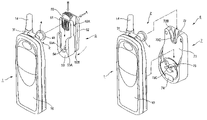
- FIG. 1 is an exploded perspective view of a cellular phone securing device according to a first embodiment of the invention and a cellular phone to which the cellular phone securing device is to be fixed;
- FIG. 2 is an explanatory view of a state in which the cellular phone securing device according to the first embodiment shown in FIG. 1 is mounted on the cellular phone;
- FIG. 3 is a perspective view of the cellular phone securing device according to the first embodiment shown in FIG. 1 , showing a state in which it is mounted on the cellular phone;
- FIG. 4 is an explanatory view of a carrying holder mounting thereon the cellular phone securing device according to the first embodiment shown in FIG. 1 ;
- FIG. 5 is an exploded perspective view of an onboard holder according to a second embodiment of the invention.
- FIG. 6 is a perspective view of the onboard holder according to the second embodiment shown in FIG. 5 and a cellular phone, showing a state in which the latter is mounted onto the former;
- FIG. 7 is an explanatory view in which the onboard holder according to the second embodiment shown in FIG. 5 with the cellular phone mounted thereon through the cellular phone securing device according to the first embodiment shown in FIG. 1 is mounted on the interior of a car body;
- FIG. 8 is a partial section view of the onboard holder according to the second embodiment shown in FIG. 5 , showing the shape of a plate spring disposed in the mounting portion thereof;
- FIG. 9 is an enlarged view of the main portions of the cellular phone securing device according to the first embodiment and the onboard holder according to the second embodiment.
- FIG. 1 shows a cellular phone securing device 2 according to a first embodiment of the invention.
- the cellular phone securing device 2 according to the present embodiment is not only to be fixed to a cellular phone 1 but also to be mounted on a carrying holder 5 (see FIG. 3 ); and, the cellular phone securing device 2 includes a main body portion 3 with securing members disposed thereon and a projecting shaft 4 serving as a holding member.
- the securing device 2 is to be mounted on the back surface portion 10 A of a casing of the cellular phone 1 . Therefore, in the central portion of one end (upper end) portion of the cellular phone 1 , there is formed a recessed portion 11 to which a securing pawl 31 (which will be discussed later) can be secured. Also, in the back surface portion 10 A of the cellular phone 1 , there is formed a recessed portion 13 in which a battery mounted on the back surface of a battery cover 12 can be stored. In the central portion of one erect surface 13 A of the recessed portion 13 , there is formed a cutaway portion 13 B into which a securing metal member 32 (which will be discussed later) can be inserted.
- an expansion portion 15 for storing therein the base portion of an antenna 14 in such a manner that the expansion portion 15 projects from the back surface 10 A by such height Hi as shown in FIG. 1 .
- the main body portion 3 is made of proper metal or synthetic resin into a substantially triangular-shaped sheet or a substantially trapezoidal-shaped sheet.
- On one end (upper end) portion and on the other end (lower end) portion of the main body portion 3 there are projectingly disposed a securing pawl (first securing member) 31 and a securing metal member (second securing member) 32 , respectively.
- a projection portion 33 to be fixed to and held by an onboard holder 6 (which will be discussed later).
- the securing pawl 31 is structured in such a manner that its section, which is obtained when it is cut in its thickness direction, has a substantially U shape (or a C shape) and it projects from one end (upper end) portion of the main body portion 3 in the back surface direction thereof.
- the securing pawl 31 is also structured such that, when it is mounted together with the securing metal member 32 on the cellular phone 1 , the main body portion 3 is raised up in a bridge manner with respect to the back surface 10 A of the casing of the cellular phone 1 (or sits astride the casing back surface 10 A in an arch manner), while the back surface of the main body portion 3 can be kept not in contact with the casing back surface 10 A (or can be kept in slight contact with the casing back surface 10 A).
- the securing metal member 32 is made of a sheet-like metal plate into a member having a substantially L-shaped section and, similarly to the securing pawl 31 , the securing metal member 32 is mounted on the main body portion 3 in such a manner that it raises the main body portion 3 in a bridge manner (or in an arch manner).
- each of the projection portions 33 is formed in a substantially L-like shape and, as shown in FIG. 1 , it includes two horizontal members 33 A projecting in the horizontal direction and a vertical member 33 B projecting in the height direction which is perpendicular to the projecting direction of the horizontal members 33 A.
- a sound hole for (not shown) for a speaker in part of the back surface 10 A of the casing of the cellular phone 1 on which the cellular phone securing device 2 can be mounted, in the area of the middle portion of the main body portion 3 that corresponds to a position just above the sound hole of the back surface 10 A, there is opened up a hole 34 which is used to facilitate the reverberation of the sound.
- the projecting shaft 4 has a hollow cylindrical shape and is fixed to the main body portion 3 in such a manner that it projects from the surface of the main body portion 3 by such height H 2 as shown in FIG. 1 .
- a flange portion 41 In the upper end portion of the projecting shaft 4 , there is formed a flange portion 41 and, in the central portion of the upper surface of the flange portion 41 , there is opened up a securing hole 41 A; and, in a case where a fixing projection formed in the carrying holder 5 (which will be discussed later) is inserted into the securing hole 41 A portion of the projecting shaft 4 , the cellular phone securing device 2 can be prevented against removal from the carrying holder 5 .
- the upper surface portion of the flange portion 41 is structured such that, as shown in FIG. 2 , an upper half section 41 B thereof extending from the central portion thereof has a plane (a horizontal surface) which is substantially parallel to the back surface portion of the cellular phone 1 , while a lower half section 41 C thereof has an inclined shape inclined downward (near to the back surface 1 A of the cellular phone 1 ) by an angle of ⁇ (similarly, see FIG. 9 ) with respect to the back surface portion of the cellular phone 1 .
- the projecting shaft 4 having the thus structured flange portion 41 even in case where it is not projected long from the main body portion 3 , as shown in FIG. 2 , when the cellular phone 1 is rotated with respect to the carrying holder 5 , an antenna 14 disposed on the casing back surface 10 A of the cellular phone 1 can be prevented against contact with the carrying holder 5 .
- the cellular phone 1 when the cellular phone 1 is rotated about the projecting shaft 4 with respect to the carrying holder 5 , the cellular phone 1 is rotated in such a manner that the upper end portion of the casing 10 with the antenna 14 mounted thereon is normally more distant from the carrying holder 5 than the lower end portion of the casing 10 , in other words, in such a manner that the upper end portion of the casing 10 is raised by an angle of ⁇ with respect to the carrying holder 5 (see FIG. 2 ).
- the carrying holder 5 as shown in FIG. 3 , generally, includes a main body portion 51 , a mounting portion 52 , a guide portion 53 , a fixing projection 54 , and a lock removing portion 55 .
- the main body portion 51 is formed in a long and narrow shape which is long in the vertical direction in FIG. 3 and, in the surface portion of the main body portion 51 , there is formed the guide portion 53 which projects therefrom in a substantially U-shaped manner.
- the guide portion 53 includes a pair of guide walls 53 A respectively formed along the two side edge portions of the main body portion 51 extending in parallel to the longitudinal direction of the main body portion 51 ; and, when mounting the cellular phone securing device 2 onto the carrying holder 5 , the projecting shaft 4 can be slid and guided downward by the guide walls 53 A.
- the fixing projection 54 (which will be discussed later): that is, in a case where the projecting shaft 4 is moved down to the lower-most portion (the deepest portion) of the guide portion 53 , the projecting shaft 4 can be fixed (locked) by the fixing projection 54 that is present on the lower-most (the deepest side) of the guide portion 53 .
- the mounting portion 52 is formed in a substantially rectangular plate having almost the same size as the main body portion 51 , the upper end portion side of the mounting portion 52 is connected to the main body portion 51 through a substantially U-shaped plate spring member 52 A, and the lower end portion side of the mounting portion 52 is open in an alligator mouth shape, That is, the mounting portion 52 is structured such that, as shown in FIG. 4 , in a case where the upper end portion thereof is pushed in the main body portion 51 direction (in FIG. 4 , in the A direction) against the spring force of the mounting portion 52 to thereby open the lower end portion side thereof, the mounting portion 52 can be inserted into and held by a belt C.
- On the lower end of the mounting portion 52 there is provided a securing projection 52 B (see FIG. 4 ) which projects toward the main body portion 51 , thereby being able to prevent the mounting portion 52 from being removed from the belt C easily.
- the fixing projection 54 is structured such that, on the lower end portion side of the main body portion 51 , it is able to project and retreat with respect to the surface of the main body portion 51 and is normally projected from the surface of the main body portion 51 by a spring (not shown). That is, in a case where the projecting shaft 4 of the cellular phone securing device 2 is inserted down to the lower end portion side of the main body portion 51 , the fixing projection 54 is fitted into and locked to the securing hole 41 A (see FIG. 1 ) opened up in the flange portion 41 which is formed in the upper end portion of the projecting shaft 4 , thereby being able to fix and hold the cellular phone securing device 2 .
- the fixing projection 54 is also structured such that, in FIG. 3 , in a case where the lock removing portion 55 thereof is depressed downwardly of the main body portion 51 , the energizing operation applied to the fixing projection 54 by the spring can be removed. In this case, the locked condition of the projecting shaft 54 is also removed and, therefore, the cellular phone securing device 2 can be removed from the carrying holder 5 .
- the cellular phone securing device 2 is secured in the two positions of the two end portions thereof to the casing 10 of the cellular phone 1 and is thereby fixed in a bridge manner (or in an arch manner): in other words, the cellular phone securing device 2 is mounted to the casing 10 so as to sit astride it between at least two positions respectively existing in the upper end portion and middle portion of the casing 10 , while the cellular phone securing device 2 is mounted in such a manner that the back surface of the main body portion 3 can be kept not in contact with it.
- the cellular phone securing device 2 is structured so as to be able to stand firm in a bridge manner, the collision impact can be absorbed and damped. This can prevent troubles that the battery can be detached from the battery cover 12 and a printed circuit board disposed in the interior portion of the casing 10 of the cellular phone 1 can be damaged.
- FIG. 5 shows an onboard holder 6 according to the second embodiment of the invention.
- the present onboard holder 6 includes a main body portion 7 and a base portion 8 and is structured such that it can fix and hold the cellular phone 1 in a rotation preventive manner through the cellular phone securing device 2 used in the first embodiment.
- the main body portion 7 includes, on the front surface 71 side thereof, a mounting portion 72 and a holding portion 73 .
- the mounting portion 72 sandwiches and mounts the cellular phone securing device 2 from both sides thereof (in FIG. 5 , in the Y direction) with spring forces, whereas the holding portion 73 sandwiches and holds, or, fixes the cellular phone securing device 2 physically from both sides thereof and from upper and lower sides thereof (in FIG. 5 , in the Y and Z directions).
- the front surface 71 is structured such that the substantially half-section area thereof, which is situated near to one end side thereof and also in which the mounting portion 72 is formed, is lower in position than the other substantially half-section area thereof situated near to the other end side thereof, while the boundary portion between these two areas is inclined.
- the height difference of the front surface 71 is set so as to be able to absorb the expansion amount of the expansion portion 15 on which the antenna base portion of the casing back surface 10 A portion of the cellular phone 1 is to be mounted.
- the mounting portion 72 is structured such that it can sandwich and mount the projecting shaft 4 of the cellular phone securing device 2 inserted into the deep portion of a slide hole 72 A from both sides thereof with spring forces.
- the slide hole 72 A as shown in FIG. 5 , is formed as a horizontal hole extending in parallel to the surface direction of the front surface 71 ; and, in order to facilitate the insertion of the projecting shaft 4 , the entrance portion of the slide hole 72 A open in one end portion of the main body portion 7 is spread out toward the outside.
- plate springs 72 B are mounted on the two side surfaces of the slide hole 72 A that are situated near to the above entrance portion. These plate springs 72 B are wholly tapered toward their respective deep portions so as to approach each other and, in the middle portions thereof, there are formed stepped portions 72 D which prevent the projecting shaft 4 of the cellular phone securing device 2 against removal to thereby lock it temporarily.
- the holding portion 73 is structured such that the projection portion 33 (see FIG. 1 ) provided on the cellular phone securing device 2 can be inserted into the holding portion 73 to thereby be able to sandwich and hold the projection portion 33 in such a manner that the movements of the main body portion 7 of the onboard holder 6 in the thickness (Z) direction as well as in the width (Y) direction thereof are physically restricted. As shown in FIG. 5 , the holding portion 73 is also structured such that the projection portion 33 can be inserted from the X direction which is the same direction as in the mounting portion 72 .
- the holding portion 73 includes a horizontal hole 73 A for restricting and holding part of the projection portion 33 (the horizontal member 33 A shown in FIG. 1 ) from the thickness (Z) direction of the main body portion 7 , and a vertical hole 73 B for restricting and holding the remaining portion of the projection portion 33 (the vertical member 33 B shown in FIG. 1 ) from the width (Y) direction; and, in order to be able to fix the projection portion 33 with no play, the horizontal and vertical holes 73 A and 73 B are formed in dimension in conformity with the horizontal and vertical members 33 A and 33 B.
- a screw hole 73 C for fixing the base portion 8 to the back surface side which is opposite to the front surface 71 side.
- a flexible pad portion 74 nearer to the end portion of the onboard holder 6 than the holding portion 73 , there is disposed a flexible pad portion 74 . That is, when the cellular phone 1 is fixed to and held by the onboard holder 6 , the pad portion 74 absorbs the vibrations of the cellular phone 1 on the car body side to thereby prevent the vibrations from being transmitted to the back surface 10 A of the casing.
- the base portion 8 is used to fix the onboard holder 6 to the interior of a vehicle such as a car. That is, when threadedly mounting the onboard holder 6 onto the interior of the car using a screw, this base portion 8 is to be used. Also, the base portion 8 is structured such that the main body portion 7 can be inclined at an inclination angle desired by a user with respect to the substantially trapezoidal-shaped upper portion of the base portion 8 and can be connected integrally to the upper portion of the base portion 8 . Between the base portion 8 and main body portion 7 , there is interposed an inclination adjust mechanism (not shown).
- this base portion 8 When fixing the onboard holder 6 directly to the interior of the vehicle using a screw, this base portion 8 is used; but, to avoid such screw fixation, for example, there may be interposed between them a stick plate 9 with both surfaces covered with adhesives. That is, the base portion 8 , which is united with the main body portion 7 screwed thereto, may be fixedly secured to the surface of the stick plate 9 and, at the same time, the back surface of the stick plate 9 may be fixedly secured to the vehicle body.
- a cellular phone securing device includes a first securing member to be secured to an erect surface in a battery mounting recessed portion formed on the back surface side of a casing of a cellular phone, and a second securing member to be secured to a recessed portion formed in the upper end face of the casing.
- the present cellular phone securing device is structured such that it can be mounted on a cellular phone so as to sit astride the cellular phone at least between the two positions of the casing through the first and second securing members.
- the back surface of the central portion of the cellular phone securing device can be prevented from touching the back surface portion of the cellular phone casing on which the cellular phone securing device is to be mounted. Owing to this, even in the portion of the casing in which a speaker, is installed, the present cellular phone securing device can be mounted in such a manner that it does not close the casing portion but sits astride it. That is, the present cellular phone securing device can be disposed even in the portion where the speaker is installed.
- the present cellular phone securing device since the present cellular phone securing device is not fixedly secured to the casing of the cellular phone with adhesives, it can be mounted onto and removed from the cellular phone according to the taste of a user; that is, the present cellular phone securing device is free to use and is thus convenient for the user to handle it.
- the present cellular phone securing device by inclining the upper surface portion of a projecting shaft provided on and projected from the present cellular phone securing device, the portion of the casing of the cellular phone with the antenna mounted thereon can be kept most distant from a carrying holder. Owing to this, even in the case of a cellular phone securing device in which the projecting amount of the projecting shaft is reduced as much as possible, the antenna can be prevented from touching the carrying holder. This makes it possible to provide a cellular phone securing device which is minimized in the bulk amount thereof and thus is easy to use.
- an onboard holder which includes a mounting portion for sandwiching and mounting a projecting shaft from both sides thereof using spring forces, and a holding portion for receiving a projection portion formed in a cellular phone securing device to sandwich and hold the projection portion.
- the cellular phone when the cellular phone is mounted on it, the cellular phone can be firmly fixed to the interior of a car, thereby being able to prevent the cellular phone from oscillating greatly according to the oscillation of a vehicle body. This can prevent the cellular phone from colliding with something existing in the interior of the vehicle, can facilitate the mounting and removal of the cellular phone with respect to the present onboard-holder, and can realize an easy key operation while mounting the cellular phone on the present onboard holder.
Abstract
Description
Claims (11)
Applications Claiming Priority (2)
| Application Number | Priority Date | Filing Date | Title |
|---|---|---|---|
| JPP.2001-240700 | 2001-08-08 | ||
| JP2001240700A JP4408595B2 (en) | 2001-08-08 | 2001-08-08 | Mobile phone device holder and in-vehicle holder device |
Publications (2)
| Publication Number | Publication Date |
|---|---|
| US20030029976A1 US20030029976A1 (en) | 2003-02-13 |
| US6955280B2 true US6955280B2 (en) | 2005-10-18 |
Family
ID=19071269
Family Applications (1)
| Application Number | Title | Priority Date | Filing Date |
|---|---|---|---|
| US10/214,067 Expired - Fee Related US6955280B2 (en) | 2001-08-08 | 2002-08-07 | Cellular phone securing device and onboard holder for vehicle use |
Country Status (2)
| Country | Link |
|---|---|
| US (1) | US6955280B2 (en) |
| JP (1) | JP4408595B2 (en) |
Cited By (39)
| Publication number | Priority date | Publication date | Assignee | Title |
|---|---|---|---|---|
| US20040232180A1 (en) * | 2003-05-19 | 2004-11-25 | Paul Badillo | Belt clip and locking fastener for selectively securing an electronic device |
| US20040251286A1 (en) * | 2002-06-26 | 2004-12-16 | Paul Badillo | Belt clip and locking fastener for selectively securing an electronic device |
| US20050035164A1 (en) * | 2002-06-26 | 2005-02-17 | Paul Badillo | Belt clip and locking fastener for selectively securing an electronic device |
| US20050072822A1 (en) * | 2003-10-01 | 2005-04-07 | Stotts Lawrence R. | All plastic clip |
| US20050092801A1 (en) * | 2003-11-03 | 2005-05-05 | Lear Corporation | Accessory strip for securing articles within a vehicle interior |
| US20050145656A1 (en) * | 2002-05-16 | 2005-07-07 | Knight Jonathan A.M. | Quick-release arrangement |
| US20060199426A1 (en) * | 2004-11-18 | 2006-09-07 | Charles Williams | Carrying assembly |
| US20070040082A1 (en) * | 2005-08-03 | 2007-02-22 | Inventec Appliances Corp. | Cable fixer for an electronic device |
| US20080112754A1 (en) * | 2006-11-09 | 2008-05-15 | Schmitz Chad D | System and method for stowage compartment pivot assembly |
| DE202008006318U1 (en) | 2008-05-08 | 2008-10-02 | E-LEAD ELECTRONIC CO., LTD., Shengang Shiang | Vehicle mount for portable electronic display device |
| US20080298026A1 (en) * | 2007-05-31 | 2008-12-04 | Micro-Star Int'l Co., Ltd. | Holder for electronic device |
| US20080305840A1 (en) * | 2007-06-11 | 2008-12-11 | Pi-Fen Lin | Clip for wireless devices |
| US20090045087A1 (en) * | 2007-08-16 | 2009-02-19 | Carnevali Jeffrey D | Portable device holder |
| US20090045234A1 (en) * | 2007-08-16 | 2009-02-19 | Carnevali Jeffrey D | Portable device holder |
| US20090242595A1 (en) * | 2007-09-27 | 2009-10-01 | Gross Travis A | Retractable carrying device for an optical device |
| US7624901B1 (en) * | 2006-12-05 | 2009-12-01 | Raymond P Mozes | Noise-free retainer for hand-held electronics |
| US7659468B1 (en) * | 2007-08-30 | 2010-02-09 | Donald Gottlieb | Guitar stand system and method of use |
| US20100206922A1 (en) * | 2007-09-27 | 2010-08-19 | Gross Travis A | Retractable carrying device for an optical device |
| US20100229284A1 (en) * | 2009-03-16 | 2010-09-16 | Jaco Clothing LLC | Lower-body garment having a secure waist assembly |
| US20100242239A1 (en) * | 2009-03-24 | 2010-09-30 | Gathering Storm Llc Dba Tmax Gear | Fastening Mechanism |
| US20110011906A1 (en) * | 2009-07-14 | 2011-01-20 | Holly Musgrave | Portable Gadget-Holding Device |
| US20110024470A1 (en) * | 2009-08-03 | 2011-02-03 | Hamid Cyrus Hajarian | Handheld device holder for vehicle's steering wheel |
| US20120305611A1 (en) * | 2011-06-06 | 2012-12-06 | Jeffrey Blood | Walking/wading staff with integral fishing net |
| US20130083507A1 (en) * | 2011-09-29 | 2013-04-04 | Edward G. Guirlinger | Display Holder Assembly |
| US8479960B2 (en) | 2011-05-03 | 2013-07-09 | Ruben Lopez-Apodaca | Portable telephone holder for sun visor |
| US8801065B1 (en) * | 2012-11-27 | 2014-08-12 | David Jones | Carrying device for an electronic device |
| US8807409B2 (en) * | 2012-12-12 | 2014-08-19 | Htc Corporation | Car holder |
| US20150001265A1 (en) * | 2013-06-27 | 2015-01-01 | John Kenison Hart | Universal mobile device holder |
| US9729186B1 (en) * | 2016-08-29 | 2017-08-08 | Allen Dill | Mobile phone holder |
| US9750333B1 (en) * | 2016-08-03 | 2017-09-05 | Humphrey Erwin Wesenhagen | Belt clip for a golf club |
| US9866677B1 (en) | 2015-10-14 | 2018-01-09 | Michael K Maguire | Mobile device monitoring system |
| US10123636B2 (en) * | 2007-02-02 | 2018-11-13 | Kratos Enterprises Holdings, Llc | Merchandise display system |
| USD874252S1 (en) * | 2018-12-04 | 2020-02-04 | Leather Pro, Inc. | Ratcheting post for an electronic accessory protective case |
| USD874253S1 (en) * | 2018-12-04 | 2020-02-04 | Leather Pro, Inc. | Racheting post for an electronic device protective case |
| USD874254S1 (en) * | 2018-12-04 | 2020-02-04 | Leather Pro, Inc. | Ratcheting post receiver for an electronic device protective case |
| US10736406B2 (en) | 2015-06-19 | 2020-08-11 | Ian Hintze | Tool retaining device |
| USD927956S1 (en) | 2019-05-03 | 2021-08-17 | We Group Europe | Hanger and support set |
| US20220045458A1 (en) * | 2020-08-10 | 2022-02-10 | Getac Technology Corporation | Connector |
| US11540649B2 (en) | 2020-04-14 | 2023-01-03 | Dorel Juvenile Group, Inc. | Carry handle anchor system |
Families Citing this family (10)
| Publication number | Priority date | Publication date | Assignee | Title |
|---|---|---|---|---|
| TW560504U (en) * | 2002-07-02 | 2003-11-01 | Qbas Co Ltd | Edge buckle structure for respiratory siphon |
| US7686196B2 (en) * | 2004-05-04 | 2010-03-30 | Michael Panosian | Retainer for detachably attaching an accessory to a utility belt |
| GB2414037B (en) * | 2004-05-14 | 2008-12-24 | Motorola Inc | Adaptor for use in carrying a mobile communications handset |
| JP4739783B2 (en) * | 2005-03-14 | 2011-08-03 | 株式会社ケイディエス | Tape measure portable holder |
| KR100819281B1 (en) * | 2006-10-30 | 2008-04-02 | 삼성전자주식회사 | Battery cover grounding device for portable terminal |
| US7818034B2 (en) * | 2007-03-30 | 2010-10-19 | Motorola, Inc. | Multi-mode pivoting carrying holder for mobile devices |
| US20120048755A1 (en) * | 2010-08-30 | 2012-03-01 | Chung Piao Tsao | Efficiently compartmentalized box for multiple functions |
| EP3188458B1 (en) * | 2015-12-29 | 2018-09-12 | Lg Electronics Inc. | Mobile terminal |
| CN108725332B (en) * | 2017-04-19 | 2023-06-02 | 福特环球技术公司 | Device holder mountable on A-pillar |
| US11228188B2 (en) * | 2018-12-20 | 2022-01-18 | David Louis Watson | Wireless charging system and method for electronic device grip holder |
Citations (13)
| Publication number | Priority date | Publication date | Assignee | Title |
|---|---|---|---|---|
| US4299344A (en) * | 1979-06-28 | 1981-11-10 | Nippon Electric Co., Ltd. | Mount for portable radio communication unit |
| US4828153A (en) * | 1983-12-07 | 1989-05-09 | Motorola, Inc. | Detachable belt clip assembly |
| US4956895A (en) * | 1986-12-25 | 1990-09-18 | Nec Corporation | Removable clip for portable equipment |
| US5054170A (en) * | 1991-03-18 | 1991-10-08 | Otrusina Edward C | Connector engageable in multiple positions and releasable in only one position |
| US5356060A (en) * | 1991-02-06 | 1994-10-18 | Nec Corporation | Structure of casing of radio pager and clip attachable thereto |
| US5730342A (en) * | 1997-04-11 | 1998-03-24 | Tien; Tse-Hsiung | Mobile telephone fastening |
| US5833100A (en) * | 1996-11-05 | 1998-11-10 | Kim; Dong-Joo | Cellular phone holder |
| US5850954A (en) * | 1997-09-20 | 1998-12-22 | Dong-Joo; Kim | Holder assembly for cellular phones |
| US5850996A (en) * | 1996-03-04 | 1998-12-22 | Two Thousand And One Technology, Inc. | Mobile telephone hanging device |
| US5906031A (en) * | 1998-04-17 | 1999-05-25 | Hughes Electronics Corporation | Rotating and locking clip for portable electronic device |
| US6006969A (en) * | 1998-06-12 | 1999-12-28 | Kim; Dong-Joo | Belt holder for portable phones |
| US6059156A (en) * | 1996-03-28 | 2000-05-09 | Lehtinen; Markku | Attachment system for a portable device |
| US20020100782A1 (en) * | 2001-01-29 | 2002-08-01 | Ernest Marvin | Cell phone holder for motor vehicles |
-
2001
- 2001-08-08 JP JP2001240700A patent/JP4408595B2/en not_active Expired - Fee Related
-
2002
- 2002-08-07 US US10/214,067 patent/US6955280B2/en not_active Expired - Fee Related
Patent Citations (13)
| Publication number | Priority date | Publication date | Assignee | Title |
|---|---|---|---|---|
| US4299344A (en) * | 1979-06-28 | 1981-11-10 | Nippon Electric Co., Ltd. | Mount for portable radio communication unit |
| US4828153A (en) * | 1983-12-07 | 1989-05-09 | Motorola, Inc. | Detachable belt clip assembly |
| US4956895A (en) * | 1986-12-25 | 1990-09-18 | Nec Corporation | Removable clip for portable equipment |
| US5356060A (en) * | 1991-02-06 | 1994-10-18 | Nec Corporation | Structure of casing of radio pager and clip attachable thereto |
| US5054170A (en) * | 1991-03-18 | 1991-10-08 | Otrusina Edward C | Connector engageable in multiple positions and releasable in only one position |
| US5850996A (en) * | 1996-03-04 | 1998-12-22 | Two Thousand And One Technology, Inc. | Mobile telephone hanging device |
| US6059156A (en) * | 1996-03-28 | 2000-05-09 | Lehtinen; Markku | Attachment system for a portable device |
| US5833100A (en) * | 1996-11-05 | 1998-11-10 | Kim; Dong-Joo | Cellular phone holder |
| US5730342A (en) * | 1997-04-11 | 1998-03-24 | Tien; Tse-Hsiung | Mobile telephone fastening |
| US5850954A (en) * | 1997-09-20 | 1998-12-22 | Dong-Joo; Kim | Holder assembly for cellular phones |
| US5906031A (en) * | 1998-04-17 | 1999-05-25 | Hughes Electronics Corporation | Rotating and locking clip for portable electronic device |
| US6006969A (en) * | 1998-06-12 | 1999-12-28 | Kim; Dong-Joo | Belt holder for portable phones |
| US20020100782A1 (en) * | 2001-01-29 | 2002-08-01 | Ernest Marvin | Cell phone holder for motor vehicles |
Cited By (51)
| Publication number | Priority date | Publication date | Assignee | Title |
|---|---|---|---|---|
| US8499986B2 (en) * | 2002-05-16 | 2013-08-06 | Hultafors Group Ab | Quick-release arrangement |
| US20050145656A1 (en) * | 2002-05-16 | 2005-07-07 | Knight Jonathan A.M. | Quick-release arrangement |
| US20040251286A1 (en) * | 2002-06-26 | 2004-12-16 | Paul Badillo | Belt clip and locking fastener for selectively securing an electronic device |
| US20050035164A1 (en) * | 2002-06-26 | 2005-02-17 | Paul Badillo | Belt clip and locking fastener for selectively securing an electronic device |
| US20060163295A1 (en) * | 2002-06-26 | 2006-07-27 | Paul Badillo | Belt clip |
| US20040232180A1 (en) * | 2003-05-19 | 2004-11-25 | Paul Badillo | Belt clip and locking fastener for selectively securing an electronic device |
| US20050072822A1 (en) * | 2003-10-01 | 2005-04-07 | Stotts Lawrence R. | All plastic clip |
| US7032791B2 (en) * | 2003-10-01 | 2006-04-25 | The Clip Company | All plastic clip |
| US20050092801A1 (en) * | 2003-11-03 | 2005-05-05 | Lear Corporation | Accessory strip for securing articles within a vehicle interior |
| US7234619B2 (en) * | 2003-11-03 | 2007-06-26 | International Automotive Components Group North America, Inc. | Accessory strip for securing articles within a vehicle interior |
| US20060199426A1 (en) * | 2004-11-18 | 2006-09-07 | Charles Williams | Carrying assembly |
| US20070040082A1 (en) * | 2005-08-03 | 2007-02-22 | Inventec Appliances Corp. | Cable fixer for an electronic device |
| US20080112754A1 (en) * | 2006-11-09 | 2008-05-15 | Schmitz Chad D | System and method for stowage compartment pivot assembly |
| US8146227B2 (en) * | 2006-11-09 | 2012-04-03 | The Boeing Company | System and method for stowage compartment pivot assembly |
| US7762737B2 (en) * | 2006-11-09 | 2010-07-27 | The Boeing Company | System and method for stowage compartment pivot assembly |
| US20100213800A1 (en) * | 2006-11-09 | 2010-08-26 | The Boeing Company | System and Method for Stowage Compartment Pivot Assembly |
| US7624901B1 (en) * | 2006-12-05 | 2009-12-01 | Raymond P Mozes | Noise-free retainer for hand-held electronics |
| US10123636B2 (en) * | 2007-02-02 | 2018-11-13 | Kratos Enterprises Holdings, Llc | Merchandise display system |
| US20080298026A1 (en) * | 2007-05-31 | 2008-12-04 | Micro-Star Int'l Co., Ltd. | Holder for electronic device |
| US20080305840A1 (en) * | 2007-06-11 | 2008-12-11 | Pi-Fen Lin | Clip for wireless devices |
| US20090045234A1 (en) * | 2007-08-16 | 2009-02-19 | Carnevali Jeffrey D | Portable device holder |
| US20090045087A1 (en) * | 2007-08-16 | 2009-02-19 | Carnevali Jeffrey D | Portable device holder |
| US8056714B2 (en) | 2007-08-16 | 2011-11-15 | Carnevali Jeffrey D | Portable device holder |
| US8061516B2 (en) | 2007-08-16 | 2011-11-22 | Carnevali Jeffrey D | Portable device holder |
| US7659468B1 (en) * | 2007-08-30 | 2010-02-09 | Donald Gottlieb | Guitar stand system and method of use |
| US20100206922A1 (en) * | 2007-09-27 | 2010-08-19 | Gross Travis A | Retractable carrying device for an optical device |
| US20090242595A1 (en) * | 2007-09-27 | 2009-10-01 | Gross Travis A | Retractable carrying device for an optical device |
| DE202008006318U1 (en) | 2008-05-08 | 2008-10-02 | E-LEAD ELECTRONIC CO., LTD., Shengang Shiang | Vehicle mount for portable electronic display device |
| US20100229284A1 (en) * | 2009-03-16 | 2010-09-16 | Jaco Clothing LLC | Lower-body garment having a secure waist assembly |
| US20100242239A1 (en) * | 2009-03-24 | 2010-09-30 | Gathering Storm Llc Dba Tmax Gear | Fastening Mechanism |
| US20110011906A1 (en) * | 2009-07-14 | 2011-01-20 | Holly Musgrave | Portable Gadget-Holding Device |
| US8356736B2 (en) * | 2009-07-14 | 2013-01-22 | Holly Musgrave | Portable gadget-holding device |
| US20110024470A1 (en) * | 2009-08-03 | 2011-02-03 | Hamid Cyrus Hajarian | Handheld device holder for vehicle's steering wheel |
| US8479960B2 (en) | 2011-05-03 | 2013-07-09 | Ruben Lopez-Apodaca | Portable telephone holder for sun visor |
| US20120305611A1 (en) * | 2011-06-06 | 2012-12-06 | Jeffrey Blood | Walking/wading staff with integral fishing net |
| US20130083507A1 (en) * | 2011-09-29 | 2013-04-04 | Edward G. Guirlinger | Display Holder Assembly |
| US8801065B1 (en) * | 2012-11-27 | 2014-08-12 | David Jones | Carrying device for an electronic device |
| US8807409B2 (en) * | 2012-12-12 | 2014-08-19 | Htc Corporation | Car holder |
| US20150001265A1 (en) * | 2013-06-27 | 2015-01-01 | John Kenison Hart | Universal mobile device holder |
| US9408456B2 (en) * | 2013-06-27 | 2016-08-09 | John Kenison Hart | Universal mobile device holder |
| US10736406B2 (en) | 2015-06-19 | 2020-08-11 | Ian Hintze | Tool retaining device |
| US9866677B1 (en) | 2015-10-14 | 2018-01-09 | Michael K Maguire | Mobile device monitoring system |
| US9750333B1 (en) * | 2016-08-03 | 2017-09-05 | Humphrey Erwin Wesenhagen | Belt clip for a golf club |
| US9729186B1 (en) * | 2016-08-29 | 2017-08-08 | Allen Dill | Mobile phone holder |
| USD874252S1 (en) * | 2018-12-04 | 2020-02-04 | Leather Pro, Inc. | Ratcheting post for an electronic accessory protective case |
| USD874253S1 (en) * | 2018-12-04 | 2020-02-04 | Leather Pro, Inc. | Racheting post for an electronic device protective case |
| USD874254S1 (en) * | 2018-12-04 | 2020-02-04 | Leather Pro, Inc. | Ratcheting post receiver for an electronic device protective case |
| USD927956S1 (en) | 2019-05-03 | 2021-08-17 | We Group Europe | Hanger and support set |
| US11540649B2 (en) | 2020-04-14 | 2023-01-03 | Dorel Juvenile Group, Inc. | Carry handle anchor system |
| US20220045458A1 (en) * | 2020-08-10 | 2022-02-10 | Getac Technology Corporation | Connector |
| US11885361B2 (en) * | 2020-08-10 | 2024-01-30 | Getac Holdings Corporation | Connector |
Also Published As
| Publication number | Publication date |
|---|---|
| US20030029976A1 (en) | 2003-02-13 |
| JP2003051873A (en) | 2003-02-21 |
| JP4408595B2 (en) | 2010-02-03 |
Similar Documents
| Publication | Publication Date | Title |
|---|---|---|
| US6955280B2 (en) | Cellular phone securing device and onboard holder for vehicle use | |
| US5060260A (en) | Mounting cradle for a portable cellular telephone | |
| US10118565B2 (en) | Apparatus for holding portable device | |
| US6739654B1 (en) | Headrest-mount display mounting structure | |
| US6585212B2 (en) | Quick release electronics platform | |
| HK1068941A1 (en) | Hinge unit and electronic apparatus using it | |
| JPS62121976A (en) | Holder for portable audio/video apparatus used in automobile | |
| US8061673B2 (en) | Portable apparatus and fastening device thereof | |
| US8631983B2 (en) | Holder | |
| EP0454297B1 (en) | Holder for a portable telephone | |
| JP2581435B2 (en) | Holding devices such as mobile phones | |
| JP2720804B2 (en) | Portable radio holding device | |
| JPH08256200A (en) | Holder for portable telephone | |
| JPH10315874A (en) | Portable telephone set holder for on-board use for car | |
| JPH0718200Y2 (en) | Phone holder | |
| JPH08214051A (en) | Holder for portable telephone set or the like | |
| JPH10173352A (en) | Electronic equipment | |
| JP2007323302A (en) | On-vehicle communication terminal device | |
| JPH06312638A (en) | Mounting device for video equipment for vehicle | |
| JP2571365Y2 (en) | Lock mechanism for detachable operation unit | |
| JP3098922B2 (en) | Storage container | |
| KR0122798Y1 (en) | Console box for a vehicle | |
| JPH09173126A (en) | Holding device for portable telephone and portable telephone case with the holding device | |
| KR20120006696U (en) | The supporter for vehicle of tablet pc fixed at protecting case | |
| JPH0619582A (en) | Information processor |
Legal Events
| Date | Code | Title | Description |
|---|---|---|---|
| AS | Assignment |
Owner name: MATSUSHITA ELECTRIC IINDUSTRIAL CO., LTD., JAPAN Free format text: ASSIGNMENT OF ASSIGNORS INTEREST;ASSIGNORS:SAITOH, EIJI;MATSUURA, KEIGO;REEL/FRAME:013314/0803 Effective date: 20020909 |
|
| FEPP | Fee payment procedure |
Free format text: PAYOR NUMBER ASSIGNED (ORIGINAL EVENT CODE: ASPN); ENTITY STATUS OF PATENT OWNER: LARGE ENTITY |
|
| FEPP | Fee payment procedure |
Free format text: PAYER NUMBER DE-ASSIGNED (ORIGINAL EVENT CODE: RMPN); ENTITY STATUS OF PATENT OWNER: LARGE ENTITY Free format text: PAYOR NUMBER ASSIGNED (ORIGINAL EVENT CODE: ASPN); ENTITY STATUS OF PATENT OWNER: LARGE ENTITY |
|
| FPAY | Fee payment |
Year of fee payment: 4 |
|
| AS | Assignment |
Owner name: EVONIK DEGUSSA GMBH,GERMANY Free format text: CHANGE OF NAME;ASSIGNOR:DEGUSSA GMBH;REEL/FRAME:024006/0127 Effective date: 20070912 Owner name: EVONIK DEGUSSA GMBH, GERMANY Free format text: CHANGE OF NAME;ASSIGNOR:DEGUSSA GMBH;REEL/FRAME:024006/0127 Effective date: 20070912 |
|
| REMI | Maintenance fee reminder mailed | ||
| LAPS | Lapse for failure to pay maintenance fees | ||
| STCH | Information on status: patent discontinuation |
Free format text: PATENT EXPIRED DUE TO NONPAYMENT OF MAINTENANCE FEES UNDER 37 CFR 1.362 |
|
| FP | Lapsed due to failure to pay maintenance fee |
Effective date: 20131018 |