US6961334B1 - Intelligence engine - Google Patents
Intelligence engine Download PDFInfo
- Publication number
- US6961334B1 US6961334B1 US09/821,507 US82150701A US6961334B1 US 6961334 B1 US6961334 B1 US 6961334B1 US 82150701 A US82150701 A US 82150701A US 6961334 B1 US6961334 B1 US 6961334B1
- Authority
- US
- United States
- Prior art keywords
- call
- information
- route
- call agent
- network
- Prior art date
- Legal status (The legal status is an assumption and is not a legal conclusion. Google has not performed a legal analysis and makes no representation as to the accuracy of the status listed.)
- Expired - Lifetime, expires
Links
Images


Classifications
-
- H—ELECTRICITY
- H04—ELECTRIC COMMUNICATION TECHNIQUE
- H04M—TELEPHONIC COMMUNICATION
- H04M7/00—Arrangements for interconnection between switching centres
- H04M7/006—Networks other than PSTN/ISDN providing telephone service, e.g. Voice over Internet Protocol (VoIP), including next generation networks with a packet-switched transport layer
-
- H—ELECTRICITY
- H04—ELECTRIC COMMUNICATION TECHNIQUE
- H04M—TELEPHONIC COMMUNICATION
- H04M3/00—Automatic or semi-automatic exchanges
- H04M3/38—Graded-service arrangements, i.e. some subscribers prevented from establishing certain connections
-
- H—ELECTRICITY
- H04—ELECTRIC COMMUNICATION TECHNIQUE
- H04M—TELEPHONIC COMMUNICATION
- H04M3/00—Automatic or semi-automatic exchanges
- H04M3/42—Systems providing special services or facilities to subscribers
- H04M3/436—Arrangements for screening incoming calls, i.e. evaluating the characteristics of a call before deciding whether to answer it
-
- H—ELECTRICITY
- H04—ELECTRIC COMMUNICATION TECHNIQUE
- H04M—TELEPHONIC COMMUNICATION
- H04M3/00—Automatic or semi-automatic exchanges
- H04M3/42—Systems providing special services or facilities to subscribers
- H04M3/42025—Calling or Called party identification service
- H04M3/42034—Calling party identification service
- H04M3/42059—Making use of the calling party identifier
-
- H—ELECTRICITY
- H04—ELECTRIC COMMUNICATION TECHNIQUE
- H04M—TELEPHONIC COMMUNICATION
- H04M3/00—Automatic or semi-automatic exchanges
- H04M3/42—Systems providing special services or facilities to subscribers
- H04M3/42025—Calling or Called party identification service
- H04M3/42085—Called party identification service
- H04M3/42102—Making use of the called party identifier
Definitions
- This invention is related in general to the field of telecommunications systems and methods. More particularly, the invention is related to an intelligence engine.
- PSTN public switched telephone network
- SS7 Signaling System 7
- the PSTN is built on a class structure of specialized devices that perform single-purpose functions. For example, Class 5 switches provide local access and call waiting; Class 4 switches provide long distance, toll calls and billing.
- Connectivity is also connection-oriented, where two devices must establish a discrete, deterministic connection or voice channel before communication can begin. The voice channel also must remain in place for the duration of the call.
- the PSTN is also a hierarchical one-to-many network that may result in traffic congestion, or blocking, thus creating the need for centralized control to proactively re-route the traffic.
- New service and feature development on this complex network is time-consuming and difficult, requiring a great deal of development time and resources.
- IP Internet Protocol
- SS7 circuit switched networks
- IP Internet Protocol
- Every packet of information carries all the necessary control information needed to connect the originating device to its destination using only the resources needed. This allows for uncomplicated (less) throttle points, geographic expansion, and transport integration.
- IP Internet Protocol
- An Internet Protocol (IP) network is typically used to handle the large amounts of time-sensitive data such as telephony data and/or video or video-on-demand data.
- TDMA time division multiplex access
- CDMA call division multiplex access
- AMPS advanced mobile phone service
- W-CDMA wideband and proposed third generation wireless systems W-CDMA, W-TDMA, and others, which provide for IP data as well as voice transfer.
- H.323 protocol environment or Session Initiation Protocol provides a way for transmitting voice communications within IP networks.
- H.323 define a set of call control, channel set-up, and code C specifications for transmitting real-time voice and video over networks that do not offer guaranteed service or quality of service—such as packet networks, and in particular, the Internet, local area networks, wide area networks, and Intranets.
- SIP is a session-layered control (signaling) protocol for creating, modifying and terminating session with one or more participants.
- a trunk (not specifically shown) is a communication line between two switching systems, such as between a central office and a private branch exchange (PBX).
- PBX private branch exchange
- ANI Automatic Number Identification
- This process is performed to insure that subscriber information such as caller ID, call blocking, and others, are correctly obtained for each of the parties to properly insure completion of the call.
- ANI Automatic Number Identification
- Such processing is inefficient because, in part, many circuits are tied up during this process.
- This “dip down” process reaches below the physical layer to perform authenticating and routing functions. For example, a single call session may require numerous (on the order of hundreds) traversals to and accesses to one or more databases. Such processing also limits the scalability of systems.
- ANI databases are typically maintained by separate management information systems (MIS). Processing wireless calls only increases the complexity of such systems. For example, routing, authentication and verification, and fraud detection require information such as, but not limited to, home location register (HLR) and/or visitor location register (VLR), in addition to ANI information to complete a call.
- HLR home location register
- VLR visitor location register
- MIN mobile identification number
- ESN electronic serial number
- IMSI international mobile subscriber identity
- IP network congestion, delay, or malfunction within an IP network is typically handled by simply re-sending data packets to a terminating party. Such retransmissions decrease network efficiency by tying up circuits that may be inoperative and provide no network self-awareness.
- an intelligence engine is provided that substantially reduces or eliminates disadvantages and problems of conventional systems.
- the intelligence engine includes a distributor layer operable to communicate with at least one call agent in a telecommunications network.
- the call agent may receive state-driven information associated with a call between an originator and a termination point.
- the intelligence engine also includes a telephony management layer.
- the telephony management layer is operable to receive a plurality of stateless requests from the distributor layer, access a database entry associated with the requests, spawn at least one request to obtain information associated with the originator and the termination point if necessary to route the call, and send the information to the call agent to route the call.
- the intelligence engine further includes a facility management command and control layer.
- the facility management command and control layer is operable to receive an indicator signal associated with the call froms the network.
- the call is controlled by the call agent.
- the facility management command and control layer is also operable to access a database entry associated with the call agent in response to the indicator signal and to reassign control of the call from the call agent to a second call agent.
- the invention provides several technical advantages. Various embodiments of the invention may have none, some, or all of these advantages.
- the invention may provide a stateless control layer that easily interfaces with state-driven call and/or IP data processing network functions. Such an advantage may reduce delays in processing that would otherwise be required with circuit or state based call processing systems.
- Yet another technical advantage of the invention is that the invention may be used with a variety of data traffic.
- the invention may be used with call processing networks such as SS7 or Session Initiation Protocol (SIP), wireless call processing networks including GSM, CDMA, TDMA, wireless 3G, and AMPS, and IP data using a variety of protocols such as H.323.
- SIP Session Initiation Protocol
- the invention may provide a centralized repository for a number of databases such as ANI databases. Such an advantage may reduce the redundancy required to maintain such information. In addition, such an advantage may also improve the ease of maintaining and/or updating the databases with new information, such as a new area code or service that may be offered.
- the invention may also provide the technical advantage of reducing the number of ports in a transit network that may be required to complete a call. For example, rather than “dipping down” through a variety of ports in a transit network to obtain information required to complete a call, the invention may intelligently spawn processes to search through a number of available databases, whether maintained in a centralized location or distributed geographically. Such an advantage may reduce the time needed to complete a call, as well as reducing the number of ports that are required to be reserved or allocated to the call. Control and intelligence layers may thus be collapsed into a single packet-based stream.
- the invention may provide the ability to perform facility management command and control. For example, should a media gateway controller for one region fail or otherwise malfunction, the invention automatically reroutes traffic to another media gateway controller without disrupting or infecting other networks.
- the invention may provide in conjunction with such malfunction automatic updating databases such as dispatch circuit, trunk, and group tables.
- embodiments of the invention enable technology vendors to interoperate with other elements in media-controlled or service layers, without having to maintain currency with other vendors' technology.
- Embodiments of the invention also allow call routing to be effected through a plurality of nested tables, which are easily modifiable to modify a customer's services. For example, allowing a particular person to place a 1-900 call is simply effected by changing an entry in a table.
- the invention allows scalability and flexibility by allowing a subscriber to add tables as needed and add to the tables as needed. Therefore, very complex sets of services and privileges may be easily provided not only for a group of subscribers but also can be easily provided for a single subscriber.
- Other technical advantages are readily apparent to one skilled in the art from the following figures, descriptions and claims.
- FIG. 1 is a block diagram of a communications network utilizing the teachings of the present invention, including a call routing and signaling system for routing a call using an IP network of the communications network;
- FIG. 2A is a block diagram of a call routing and signaling system of FIG. 1 , which includes a call control engine and an intelligence engine;
- FIG. 2B is a block diagram of a database storing a plurality of tables for use with the call control engine of FIG. 2A ;
- FIG. 3 is a flow chart illustrating steps associated with the call routing and signaling system of FIG. 1 processing a service request or call, over the communication network of FIG. 1 ;
- FIG. 4A is a flow chart showing steps associated with the call control engine of FIG. 2A processing a service request, or call from the PSTN to the IP network of the communication network of FIG. 1 ;
- FIG. 4B is a flow chart showing steps associated with the call control engine of FIG. 2A processing a service request, or call from the PSTN to the IP network of the communication network of FIG. 1 ;
- FIGS. 5A and 5B are schematic drawings showing tables and steps associated with the call control engine of FIG. 2A processing an operator services call, with no number provided.
- FIGS. 6A and 6B are schematic drawings showing tables and steps associated with the call control engine of FIG. 2A processing a carrier access code service request, dialed without digits, originating from the PSTN of FIG. 1 for termination in the IP network of FIG. 1 ;
- FIGS. 7A and 7B are schematic drawings showing tables and steps associated with the call control engine of FIG. 2A processing an international, calling party requested, service request originating from the PSTN of FIG. 1 for termination in the IP network of FIG. 1 ;
- FIGS. 8A and 8B are schematic drawings showing tables and steps associated with the call control engine of FIG. 2A processing free service access code service requests originating from the PSTN of FIG. 1 for termination in the IP network of FIG. 1 ;
- FIGS. 9A and 9B are schematic drawings showing tables and steps associated with processing a premium services access code service request originating from the PSTN of FIG. 1 for termination in the IP network of FIG. 1 ;
- FIGS. 10A and 10B are schematic drawings showing tables and steps associated with the call control engine of FIG. 2A processing an operator with digits dialed service request originating from the PSTN of FIG. 1 for termination in the IP network of FIG. 1 ;
- FIGS. 11A and 11B are schematic drawings showing tables and steps associated with the call control engine of FIG. 2A processing an international operator with digits dialed service request originating from the PSTN of FIG. 1 for termination in the IP network of FIG. 1 ;
- FIGS. 12A and 12B are schematic drawings showing tables and steps associated with the call control engine of FIG. 2A processing local call service request originating from the PSTN of FIG. 1 for termination in the IP network of FIG. 1 ;
- FIGS. 13A and 13B are schematic drawings showing tables and steps associated with the call control engine of FIG. 2A processing a local operator with digits service request originating from the PSTN of FIG. 1 for termination in the IP network of FIG. 1 ;
- FIGS. 14A and 14B are schematic drawings showing tables and steps associated with the call control engine of FIG. 2A processing an emergency service request originating from the PSTN of FIG. 1 for termination in the IP network of FIG. 1 ;
- FIG. 15 is a schematic drawing showing tables and steps associated with the call control engine of FIG. 2A processing a calling address not found error;
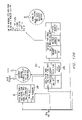
- FIG. 16 is a block diagram of one embodiment of a network topology based on the intelligence engine of the present invention.
- FIG. 17 is a graphical illustration of an embodiment of the intelligence engine constructed according to the teachings of the present invention.
- FIG. 18 is a graphical illustration of an embodiment of the operations of an information management layer for processing call events according to the teachings of the present invention.
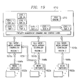
- FIG. 19 is a graphical illustration of an embodiment of the operations of a facility management command and control layer according to the teachings of the present invention.
- FIGS. 1 through 19 of the drawings like numerals being used for like and corresponding parts of the various drawings.
- FIG. 1 is a block diagram of a communications network 10 utilizing the teachings of the present invention.
- Communication network 10 includes a public switched telephone network (PSTN) 12 and an Internet Protocol network (IP) 14 .
- PSTN public switched telephone network
- IP Internet Protocol network
- a call routing and signaling system 16 and a media gateway 18 provide connectivity between PSTN 12 and IP network 14 .
- Call routing and signaling system 16 also provides connectivity to wireless systems such as base station radio systems 15 , and base station or radio gateway 17 , which is operable to connect to wireless systems 19 .
- Base station radio systems 15 may include, but are not limited to, AMPS, GSM, CDMA, and TDMA technologies
- base station or radio gateway 17 may include, but is not limited to, GSM, W-CDMA, W-TDMA, and GPRS technology, which may be then be coupled to third generation (3G)/GPRS base station radios.
- Wireless systems may include the use of wireless devices such as mobile phones, personal digital assistance (PDAs), and others.
- PSTN 12 is one example of a network that utilizes Signaling System 7 (SS7) signaling protocol to control call processing.
- public switched telephone 12 represents a worldwide voice telephone network, which in the U.S. was formerly known as the Bell System Network or the ATT Long Distance Network; however, PSTN 12 represents any network having a first type of communication protocol, for example SS7, that is different from that of another network with which it communicates, such as IP.
- Public switched telephone number 12 uses SS7 protocol to control calls within a network and outside the network, as shown by arrow 20 .
- IP network 14 is a network that utilizes IP for communications, and in particular, in this example, Session Initiation Protocol (SIP); however, IP network 14 represents any network that utilizes a second type of communication protocol, for example, IP, that is different from that of another network with which it communicates, such as SS7.
- SIP supports five facets of establishing and terminating multi communications: user location (determination of the end system to be used for communication); user capabilities (determination of the media and media parameters to be used); user availability (determination of the willingness of the calling party to engage); call setup (“ringing,” establishment of call parameters of both called and calling party); and call handling (including transfer and termination of calls).
- IP network 14 uses Session Initiation Protocol, or SIP, which is a session-layered control (signaling) protocol for creating, modifying and terminating sessions with one or more participants, both within IP network 14 and outside IP Network 14 , as illustrated by reference in row 22 .
- SIP Session Initiation Protocol
- Call routing and signaling system 16 is implemented in this example by a combination of software and hardware known as Intelligent IP (INIP) and is described in greater detail below in conjunction with FIG. 2A .
- Call routing and signaling system 16 provides SS7 protocol to IP interface and coordinates the SS7 view of IP elements and the IP view of SS7 elements.
- Call routing and signaling system 16 performs functions analogous to the service switching point, or signal switching point (SSP) traditionally used within an SS7 network.
- SSP signal switching point
- a media gateway 18 terminates switched telephone lines in public switch telephone network 12 and packetized media streams for IP transport over IP network 14 .
- Media gateway 18 terminates public switched telephone lines, which may be T1 lines, E1 lines or other suitable media, as denoted by reference numeral 24 .
- lines 26 On the IP network 14 side of media gateway 18 , are lines 26 which may also be T1, E1 or other suitable lines, but carry IP transmissions.
- Media gateway 18 and call routing and signaling system 16 utilize a Media Gateway Control Protocol (MGCP), which is a combination of the Internet Protocol Device Control (IPDC) specification and the simple Gateway Control Protocol (SGCP), which enable external control and management of media gateway devices by software programs known as call agents or media gateway controls to communicate over line 27 .
- MGCP Media Gateway Control Protocol
- IPDC Internet Protocol Device Control
- SGCP Simple Gateway Control Protocol
- Communication network 10 operates as follows: A service request, or call, originates at PSTN 12 .
- Signaling associated with the call which in this embodiment is according to the SS7 protocol, travels to signaling gateway 16 , as denoted by reference numeral 20 .
- Call routing and signaling system 16 receives the SS7 signaling, converts the signaling into an internal format, processes the calls, and generates SIP signaling, as denoted by reference numeral 22 , for transmission to IP network 14 .
- the content of the call travel over public switch telephone lines 24 through media gateway 18 and over line 26 , now according to IP for termination within Internet Protocol network 14 . Calls originating from IP network 14 are handled in a converse manner.
- Wireless calls may also be received by call routing and signaling system 16 , which may convert the signaling into an internal format, process the calls, and generate signaling for transmission to either IP network 14 or PSTN 12 .
- FIG. 2A is a block diagram of call routing and signaling system 16 comprises a plurality of hardware and software forming various functional units.
- call routing and signaling system 16 includes a resource manager 28 , a signaling agent 30 , a media gateway agent 32 , a call control engine 34 , a router/intelligence engine (“intelligence engine”) 36 , and OAM & P GUI 38 .
- Resource manager 28 determines and stores the trunks associated with both PSTN 12 and IP network 14 that are in use; therefore, resource manager 28 knows which trunks are out of service.
- Signaling agent 30 translates messages received from either public switch network 12 or IP network 14 or call control/engine 34 , and provides signaling necessary to route calls to either public switch network 12 or IP network 14 based on the route determined by call control engine 34 and intelligence engine 36 .
- Call control engine 34 performs a number of functions, which are described in detail below. For example, call control engine 34 validates that a calling party is a valid caller, determines what services are available for the caller, determines what to do with the call, and once it figures out what to do with the call, packages the call and sends it to intelligence engine 36 . Call control engine may communicate with external databases 40 over communication line 43 to process calls. Call control engine is described in greater detail below in conjunction with FIGS. 2B through 15 .
- Intelligence engine 36 performs functions related to call control. Intelligence engine 36 determines what route the call will take, and in doing so, also communicates with database 40 over line 43 . Intelligence engine 36 is described in greater detail below in conjunction with FIGS. 16–19 .
- OAM & P GUI 38 provide user interaction through a graphical user interface to allow a user 39 to configure network controller 16 and provision tables in database 40 . Additional details of database 40 are described in conjunction with FIG. 2B .
- FIG. 2B is a block diagram of database 40 shown in FIG. 2A .
- These tables include a trunk attribute table 42 , a subscriber translation table 44 , a SIP proxy routing table 46 , a calling address attribute table 48 , a dialed digits analysis table 50 , a local dial plan table 52 , a calling address privilege table 54 , an outbound privacy table 56 , a route plan table 58 , an error table 60 , and a local route table 62 . Examples of each of these tables are provided below in tables 1 through 9 and 11, and are described below in conjunction with FIGS. 5A through 15 . These tables point to additional tables that are not explicitly shown in FIG. 2B .
- route plan table 58 points to many route tables (as described in greater detail below), including, for example, TABLE 10: LD InterLATA Table.
- database 40 may also include a variety of tables used for routing, authentication and verification, and fraud detection, items especially advantageous for processing of wireless calls. These tables may include information such as, but not limited to, ANI verification 41 , home location register (HLR) and/or visitor location register (VLR) (HLR/VLR) and IMSI information 43 , billing and call detail records (CDRs) 45 , sales 47 , management information systems (MIS) 49 , and other information that may be used to provide services and/or features to customers. Integration of such billing functions may be customized according to the application, and may improve efficiency for maintaining and integrating functions such as billing, sales, and management information systems with call events that occur in call routing and signaling system 16 .
- HLR home location register
- VLR visitor location register
- IMSI information 43 IMSI information 43
- CDRs billing and call detail records
- sales 47 sales 47
- MIS management information systems
- Integration of such billing functions may be customized according to the application, and may improve efficiency for maintaining and integrating functions such as billing, sales, and
- Database 40 may also include information such as correlation tables that may be used in verification for wireless calls in conjunction with an international mobile subscriber identifier (IMSI), and additional tables which may aid in verifying subscriber information and/or services that are provided to an origination or termination party.
- Database 40 may also include information such as dispatch circuit tables, dispatch trunk tables, and dispatch group tables. These tables may facilitate rerouting of logical connections when network congestion or malfunction is suspected and/or detected.
- Database 40 may be constructed using a variety of methods, including object oriented, relational and/or hierarchical database techniques. Database 40 may also include flat files, tables or any other structure suitable for storing and/or retrieving the information desired during call processing and/or data processing events. The operation of call routing and signaling system 16 is described in conjunction with FIG. 3 with reference to FIGS. 1 and 2A .
- FIG. 3 is a flow chart illustrating steps associated with call control engine 34 processing a service request, or call, over communications network 10 .
- a service request is originated from within either public switched network system 12 or IP 14 , and signaling is sent (SS7 or SIP, especially) to signaling agent 30 .
- Signaling agent 30 translates that signaling for call control engine 34 at step 68 .
- this formatting provides a calling address format required by all call control engine 34 .
- the translated message is passed to call control engine 34 at step 70 .
- Call control engine 34 and route intelligence engine 36 process to call at step 72 , determining the route the call should take.
- resource manager 28 informs intelligence engine 36 of the available trunks over which a call may be routed in response to call processing by call control engine 34 , and intelligence engine 36 selects the route accordingly.
- Call control engine 34 processing includes determining the calling address privilege level and the call type and call attributes being requested.
- Intelligence engine 36 in conjunction with resource manager 28 verifies the destination requested is a valid telephone number and will calculate the appropriate route to use to terminate the call.
- gateway agent 32 communicates with media gateway 18 over line 27 using Media Gateway Control Protocol.
- call control engine 34 and intelligence engine 36 process a call through a series of indexed tables in database 40 that are easily modified. Because a call processing is determined by table entries, the way in which calls are processed may be changed efficiently without complex new programming typically associated with routing calls. Additional details of call processing by all call control engine 34 and intelligence engine 36 are described below in conjunction with FIGS. 4A through 15 .
- FIG. 4A is a flow chart showing additional details of steps associated with call control engine 34 processing a service request or call, from PSTN 12 to IP network 14 .
- the process begins at step 78 where a translated SIP message is received by call control engine 34 from signaling agent 30 , as denoted by reference numeral 79 .
- call control engine 34 creates an instance of a calling address profile, indicated by reference numeral 82 , for each service request received.
- a calling address profile is comprised of data defining the call type, with associated call attributes, the clients call privileges, and the final routing information to be used to determine the call.
- An example of a calling address profile 82 is calling address profile 166 in FIG. 5B .
- Call control engine 34 generates respective portions of calling address profile 82 by screening the calling address number (step 80 ), screening the called address (step 84 ), screening access privileges (step 92 ), and routed/intelligence engine 36 determining the call routing (step 94 ) and selecting an appropriate circuit (step 98 ).
- Each portion of calling address profile 82 generated by each of these steps is available for use in the subsequent step as shown generally in FIG. 4A by the reference numerals 80 , 84 , 92 , 94 , and 98 .
- Calling address profile 82 is used at the end of this process to create and send outbound messages.
- call control engine 34 screens the calling party by examining the calling address from the translated IP message.
- the calling address received by call control engine 34 may be alphanumeric, in URL or e-mail format digits in E.164 or NPA-NXX-XXX format, or other suitable format.
- call control engine 34 retrieves information from calling address attribute table 48 that define the caller's access privileges, a dialed digits analysis to use, and the client's special routing instructions.
- call control engine 34 uses the calling address to access calling address attribute table 48 , denoted by reference numeral 49 .
- Calling address attribute table 48 provides a calling privilege index, a dialed digit analysis index, a local dial plan index, a route plan index, a treatment index, a PIC code, an LPIC, a billing index, originating information, jurisdiction information, the home NPA or 911 routing table, and an outbound privacy index associated with that calling address and billing address. Each of these terms are defined below in conjunction with Table 4 (calling address attribute table 48 ).
- Error table 60 ( FIG. 7B ) is accessed through the treatment index in calling address attribute table 48 (Table 4). Error table 60 will treat the call accordingly, based on the treatment index and the error code. If a treatment index is not associated with the calling party, a default error table is used.
- call control engine 48 screens the called address number at step 84 with components of calling address attribute table passed on to the step, as denoted by reference numeral 81 .
- Call control engine 34 accesses dialed digits analysis table 50 and local dial plan table 52 to screen the called address, as denoted by reference numerals 51 and 53 .
- call control engine determines from called digits analysis table 50 the call type with associated attributes 88 (see also FIG. 5B ). Additionally, at this step, call control engine 43 analyzes the called party's local dial plan to determine if the dialed digits conform to the dialing standards required by the local calling area.
- call control engine 34 After call control engine 34 verifies that the called address has been dialed correctly, it uses the call type and call attributes to select an appropriate route list table (such as route list table 162 of FIG. 5B ) from route plan table 58 to determine the outbound route for use for call completion and to compose a PSTN message to set up the call.
- the route list table contains a route set providing possible routes for completion of the call.
- Intelligence engine 36 selects the ultimate circuit used.
- a call control engine such as call engine 34 sequentially analyzes the dialed digits as defined in the North American LSGGR standards to determine the call type and call attributes. As such, a user such as a user interacting through OAM & P GUI 38 should specify the length of acceptable digits and the range of acceptable values for each call type and each call attribute.
- call control engine 34 uses a local dial plan index (from calling address attribute table 48 ) to retrieve the local dial plan table 52 specific to the calling party.
- Data in local dial plan table 52 dictates the maximum and minimum format required to be dialed for each call case. If a local dial plan requirements have been violated, an error will be generated and error processing will be invoked.
- call control engine 34 screens access privileges at step 92 . To do so, call control engine 34 may utilize calling address privilege table 54 . At this step, call control engine 34 assesses call type and call attributes 88 to determine if the calling address has the privileges to place the call. Call control engine 34 identifies privilege levels and provide a user, such as user 39 , the ability, through OAM & P 38 and to assign, modify, or remove any combination of privileges to any calling address.
- the following privileges may be assigned: emergency services (e.g., 911) local and special codes and service, operator assisted, Intra-LATA toll calls, international calls, carrier access code (CAC) calls, and service access code (SAC)calls, (e.g., 800, 900). Additional calls that may be provided are SIP address calls and per use calls. If call control engine 34 finds the calling address does not have the privilege level to complete the call requested, an error will be generated and error processing will be invoked. If the calling address does have the privilege to complete the call, then a call type allowed flag (not explicitly shown) is set and call control engine and router/intelligence engine route the call at Step 94 .
- emergency services e.g., 911
- CAC carrier access code
- SAC service access code
- call control engine 34 retrieves outbound privacy information using an outbound privacy index (index 132 in FIG. 5A ) stored in calling address attributes Table 58 .
- This index 132 indicates which outbound privacy table 56 call control engine 34 looks to determine privileges.
- This outbound privacy table 56 dictates whether or not privacy indicators need to be set in the terminating PSTN message. Privacy may be required for the calling party address, the calling party name, or the calling party IP address. Privacy may be indicated for any of these parameters in one of three ways: the SIP message header may include a parameter indicating that privacy should be invoked, alternatively, the dialed digits may contain the *67 prefix indicating privacy; lastly, a subscriber may specify privacy across all calls. In the last case, outbound privacy table 56 states which parameters need to be suppressed. If any of these three indicators is detected by call control engine 34 , the appropriate calling party information is suppressed in the final PSTN message.
- Call control engine 43 uses a route plan index (index 116 in FIG. 5A ) together with the call type and call attributes 88 to retrieve an appropriate route list table.
- a route list table is a table specified by route plan table 58 and specifies a set of routes, or route set, that may be used to complete the call.
- Example route list tables are found in the third column of Table 9: Route Plan Table.
- Call type and call attributes 88 are keys to route plan table 58 (e.g., they determine which values from the table are used).
- call control engine 34 determines the route at step 94 , calling address profile 82 is complete, as indicated by reference numeral 82 between steps 94 and 98 .
- Call control engine 34 uses calling address profile 82 and call type and call attributes 88 to determine the route to use to complete the call request and to formulate the PSTN message to be sent, and provides the determined route, or route set, to resource manager 28 to choose the outbound circuit at step 98 .
- Call control engine 34 receives the outbound circuit and sends it and the calling address profile at step 100 to signaling agent 30 to create and send the PSTN call setup message, per, in this example, GR3 317 specifications. The process concludes at step 102 .
- FIG. 4B is a flow chart showing additional details of steps associated with call control engine 34 processing a service request, or calls from IP network 14 to PSTN 12 .
- the method begins at step 394 where signaling agent 30 provides a translated SS7 message to control engine 34 , as denoted by reference numeral 396 .
- call control engine 34 identifies the called party (rather than calling address), call type and attributes, and determining the destination at which the call should terminate. This process is described below.
- call control engine 34 performs trunk screening. Call control engine 34 creates an instance of a called party profile (not explicitly shown) for each service request received. This is in contrast to calling address profile 82 created for calls originating in PSTN 12 .
- a called party profile is comprised of data defining the call type and call attributes, such as call type and call attributes 88 , called party call privileges, and the final routing information to be used to terminate the call. Therefore, call control engine 34 accesses tables based upon the called number that define the called party's destination, privileges, and special routing instructions.
- Trunk attribute table 42 contains a subscriber translation index, an SIP proxy routing index, the call attribute/call type index, and CLLI.
- the subscriber translation index points to subscriber translation table, which provides formats for the calling party (or called address in case of on-net calls).
- the SIP proxy routing index in trunk attribute table 42 (see TABLE 1: Trunk Attributes Table) is the pointer to the SIP proxy routing table, which provides the SIP proxy to be used on the domain.
- the call type attribute index in trunk attribute table 42 defines what call types are associated with the trunk.
- the CLLI index in trunk attribute table 42 provides the common location language identifier that is associated with the trunk and will be populated in SS7 messages.
- call control engine 34 assumes there are no special privileges to find and proceeds to call type identification. If the trunk ID is found, the called party privileges are returned and used to determine whether the call should be terminated. This helps determine how the call is routed. If a processing error arises, an error is generated and error processing is invoked.
- call control engine 34 On completion of trunk screening, call control engine 34 identifies call type at step 400 of trunk screening. Trunk screening at step 398 provides an index for subscriber translation table 44 for the incoming trunk identification in trunk attribute table 42 .
- Trunk screening at step 398 provides an index for subscriber translation table 44 for the incoming trunk identification in trunk attribute table 42 .
- call control engine 34 accesses subscriber translation 44 table, if an SIP URL, IP address or e-mail address is associated with the number, this specifies that the termination is an SIP termination. However, if there is no SIP URL, IP address, or e-mail address, this specifies that the termination is a non-SIP termination.
- Step 400 of subscriber translation generates a call type 88 .
- call control engine 34 Based on call type 88 , trunk profile 399 , and the original translated SS7 message, call control engine 34 performs access privilege screening in an analogous manner as the access privilege screening of step 92 , described above in conjunction with FIG. 4A .
- call control engine 34 routes the call. To do so, remaining data necessary to create and route an SIP message are assembled at step 406 . This includes identifying the destination proxy. To accomplish this task, call control engine 34 determines the called party's domain name from the SIP address. The domain name is then used as a key in accessing SIP proxy routing table 46 . SIP proxy routing table 46 dictates which proxy is used to terminate the call. SIP proxy routing table 46 also allows user 39 to assign several NPA-NXXs to one CMS. The process concludes at step 408 .
- a caller calls from IP network 14 to a destination in PSTN 12 .
- the called number is simply “0”, indicating an operator.
- Calling address attributes table 48 (which is also shown as TABLE 4: Calling Address Attributes Table) includes a plurality of indices. Those indices are: dialed digits analysis index 110 , local dial plan index 112 , calling address privilege index 114 , route plan index 116 , treatment index 118 , “911” index 130 , and outbound privacy index 132 . Calling address attributes table 48 also includes variables that are not indices, but rather actual values. Those are: PIC 120 , LPIC 122 , JIP 124 , II 126 , HNPA 128 , billing 134 , and billing address 132 . Each of these indices or variables is described in greater detail below in conjunction with TABLE 4: Calling Address Attributes Table.
- a key for calling address attribute table 48 is the calling party number.
- a calling address attribute table exists for each calling party number.
- the calling party number, or calling address may be alphanumeric, may be in URL or e-mail format, or may be digits in e.164 or NPA-NXX-XX format.
- Dialed digits analysis index 110 is a pointer to dialed digits analysis table 50 , as indicated by reference number 138 .
- Local dial plan index 112 is a pointer to local dial plan table 52 , as indicated by reference number 140 .
- Local dial plan table 52 identifies, based on the calling party, what the user's local dial plan looks like, i.e., for each particular call type, the format of the number, including maximum and minimum number of digits.
- Calling address privilege index 114 is a pointer to calling address privilege table 54 as indicated by referenced numeral 142 .
- Calling address privilege table 54 identifies the call type restrictions for a particular calling party.
- Route plan index 116 which is based on the calling party, along with other keys, is a key to route plan table 58 , as demonstrated by reference numeral 144 .
- Route plan table 58 specifies a route list table, such as route list table 162 ( FIG. 5B ).
- Route list table 162 in turn specifies which route set to use, which is based on the calling party's profile (route plan index 116 ) and other factors as the case may be, such as call type, and LPIC index 122 and PIC index 120 .
- Treatment index 118 is a pointer to error table 60 .
- Error table 60 is used to decide what type of treatment to use based on a particular error condition and the calling address.
- PIC 120 is the calling party's long distance carrier ID code.
- LPIC 122 is the calling party's local service provider carrier ID code and is used as a key to route list table 162 , as denoted by reference numeral 148 .
- LPIC 122 is provided in this example to local route table 162 as indicated by reference numeral 148 .
- JIP 124 refers to jurisdiction information and identifies the switch from which the call originates and can be recorded to identify that switch.
- II 126 identifies the originating line. For example, if the calling party is calling from a prison phone, pay phone or regular phone.
- HNPA Numberering Plan Area index
- NPA Number of Plan Area index
- “911” index 130 is a pointer to the 911 route table to identify what 911 route set to use for the calling user.
- Outbound privacy index 132 is a pointer to outbound privacy table 56 , as indicated by reference numeral 150 .
- Billing 134 identifies the billing rate to use for the calling user.
- Billing address 136 is the address that the call is billed to, and may be alphanumeric, URL, or e-mail format, or may be digits in E164 or NPA-NXX-XXX format.
- Call control engine 34 processes this example call as described below.
- call control engine 34 screens the calling party to determine the calling party privileges. To do this, call control engine 34 examines calling address attribute table 48 . In particular, the caller in this example has a calling party privilege index 114 of “4.” This index therefore points to a particular calling address privilege table 54 that has only “976” numbers restricted.
- call control engine 34 screens the called party to determine the call type. In particular, dialed digits analysis index 110 , which for this calling party is “1”, points to a particular dialed digits analysis table 50 .
- the call type and call attributes 88 is determined to be “local operator call without digits.”
- the call type and call attributes 88 for this particular call are used as a key to select an appropriate route list table from route plan table 58 , as denoted by reference numeral 156 .
- call control engine 34 screens privileges to determine if the particular call type 88 is allowed.
- the call type 88 is a local operator call without digits.
- Calling address privilege index 114 identifies a calling address privilege table 54 , which specifies that the only restrictions on the calling party are 976 numbers; therefore, the call type is allowed.
- a route plan table 58 is indexed by route plan index 116 and call type and attributes 88 . These two indices specify the route list table listed in route plan table 58 that is be used for the call.
- the route list table selected ( 162 ) is identified as “LocalOp” Route Table.
- Selected route list table 162 is an example of a plurality of route list tables that include list of routes that can be used to terminate the call request. This list is referred to as a route set.
- the route set is LocalOp Route Set 164 .
- This route set 164 is passed, as denoted by reference numeral 166 , for use by resource manager 28 to choose the route, or outbound circuit (denoted by “Ckt a”).
- Route manager 28 chooses the outbound circuit by mapping the route set to difference CLLIs.
- the CLLIs point to a trunk group, and there are different circuits in each trunk group.
- Call control engine 34 receives the outbound circuit and provides it and calling address profile 166 to signaling agent 30 , as denoted by reference numeral 168 .
- signaling agent 30 creates and sends the outbound message based upon the selected circuit and incorporates any outbound privacy restrictions denoted by outbound privacy table 56 . In this case no outbound privacy restrictions are in place.
- signaling agent 30 formats information received from call control engine 34 into a proper signaling format message.
- FIGS. 6A and 6B are schematic diagrams showing tables and steps associated with processing a carrier access code request.
- FIGS. 6A and 6B illustrate processing of a carrier access code call that is dialed without digits “10109000.” In this example, “0900” represents the carrier. Differences between call control engine 34 processing the call of FIGS. 5A and 5B and call of FIGS. 6A and 6B are highlighted below.
- the calling address specifying table 48 is the same as in FIGS. 5A and 5B because this table is keyed off of the calling party address, which is the same (972-301-4900).
- call control engine 34 screens the calling party in calling party a similar manner to step 152 .
- call control engine 34 screens the called party.
- Call control engine 34 screens the called party using dial digits analysis table 50 , using dialed digit analysis index 110 and the called party number as keys.
- the called party number is “10109000.”
- the first three digits “101” indicate that the call is a carrier access code call, as denoted by reference numeral 174 .
- Call control engine 34 then examines the next four digits of the call, which in this case is the service number, or identifier of the actual carrier (0900). The next digit examined “0”, specifies the call is to an operator, as denoted by reference numeral 176 .
- Call control engine 34 then evaluates the next digit.
- a call attribute of operator without digits is set, as denoted by reference numeral 180 .
- the dialed digits are analyzed to determine call attributes (such as blocking calling party ID presentation—*62) and call type (such as operator, long distance, international, local, etc.). If additional digits were dialed, such as the actual phone number of a called party, they are analyzed after the appropriate route table is located.
- Route plan table 58 uses call type and attributes 88 , as denoted by reference numeral 182 as a key in selecting an appropriate route list table.
- route plan table 58 also uses as a key route plan table index 116 , as denoted by reference numeral 184 .
- call control engine 34 selects the appropriate route list table from route plan table 58 .
- the selected route list table 186 is “LDOP Route Table 186 .”
- Route list table 186 stores the list of routes that can be used to terminate the call request, or route set 188 .
- Resource Manager 28 provides route set 188 , as described above and indicated by reference numeral 190 .
- Resource Manager 28 chooses the outbound circuits as designed by reference numeral 192 .
- Call control engine 34 adds the determined circuit information to call address profile 194 and provides it to signaling agent 30 , as indicated by reference numeral 196 .
- Signaling agent creates and send the outbound message according to provided data 194 .
- FIG. 7 are schematic diagrams showing tables and steps associated with processing an international, calling party requested request.
- FIGS. 7A and 7B illustrates the call processing of an international calling party restricted phone call, which in this example is “*6701144331234567.” Only differences between call processing of FIGS. 5A and 5B and 7 A and 7 B are described.
- dialed digits analysis table 50 is accessed.
- the digits “*67” indicate to suppress the calling party number, as indicated by reference numeral 198 .
- Call control engine 34 determines the call is an international call based on the digits “011.” The remaining digits (44331234567) do not affect how the tables are assessed, but are analyzed in conjunction with an appropriate route table, as indicated by reference numeral 202 .
- call control engine 34 uses route plan table 58 to select an appropriate route list table 204 , which in this case is “LD Inter LATA” Route Table.
- Route list table 204 specifies route set 206 .
- Call control engine 34 provides route set 206 to resource manager 28 , as indicated by a reference numeral 208 .
- Resource manager 28 selects an appropriate circuit for terminating the call as indicated by reference numeral 210 .
- FIGS. 8A and 8B are schematic diagrams showing tables and steps associated with processing free service access code requests.
- FIGS. 8A and 8B show call processing for a free service access code, in this example “800-555-1212.”
- call control engine 34 determines from dialed digits analysis table 50 that the call type is a free service access code call at step 216 .
- call control engine 34 selects from call plan table 58 a route list table 218 , which in this case has a title of “Free SAC Route Table.”
- Route list table specifies route set 220 to provide to resource manager 28 as described in above, and indicated by reference numeral 222 .
- Resource manager 28 selects an appropriate circuit, as described previously.
- FIG. 9 are schematic diagrams showing tables and steps associated with processing a premium services access code request.
- FIGS. 9A and 9B illustrate an example of call process for a premium service access code call such as “900-333-1212.” Based on the called digits “900,” call control engine 34 then determines from dialed digits analysis 50 at step 226 that the call type 88 is a premium service access code call, as illustrated by reference numeral 238 .
- Call control engine 34 uses this call type 88 to identify within route plan table 58 a route list table 230 , which in this case has a title “Premium SAC Route Table.”
- Route list table 230 specifies a route set 232 having a title in this case of “premium SAC route set.”
- Route set 232 is provided to resource manager 28 as denoted by reference numeral 234 .
- Resource manager 28 determines the appropriate circuit for completing the call, as denoted by reference numeral 236 , and processing proceeds as described above.
- FIG. 10 are schematic diagrams showing tables and steps associated with processing an operator with digits dialed request.
- FIGS. 10A and 10B show call processing for an operator with digits call, for example, “08048471234.”
- the call type 88 is an operator with digits call, as denoted by reference numeral 238 .
- the call type 88 is an operator with digits call, as denoted by reference numeral 238 .
- the digits “8048471234” call type and attributes 88 is determined to additionally include the fact that the call is a long distance operator with digits. This is indicated by reference numeral 240 .
- Call control engine 34 utilizes this call type and attributes 88 in conjunction with route plan table 58 to select a suitable route list table 242 .
- route list table 242 has a title of “LD OP Route Table.”
- Route table 242 specifies a route set 244 , which is provided to resource manager 28 , as indicated by reference 246 .
- Resource manager 18 selects an appropriate circuit at step 248 in a similar manner to that described above.
- FIG. 11 are schematic diagrams showing tables and steps associated with processing an international operator with digits dialed request.
- FIGS. 11A and B show call processing for an international operator with digits call, such as for example, “0144334561234.”
- the call type 88 is an operator with digits call. This is indicated by reference numeral 250 .
- the call type 88 is additionally an international operator call with digits. This is indicated by reference numeral 252 .
- the next eleven digits “44334561234” are used when the call is routed to the operator, as designated by reference numeral 254 .
- call control engine 34 determines from route plan table 58 an appropriate list table 256 , which in turn specifies an appropriate route set 258 .
- Route set 258 is provided to resource manager 28 as indicated by reference numeral 260 , and resource manager 28 selects an appropriate circuit, as noted by reference numeral 262 . Call processing from this point continues as described above.
- FIGS. 12A and 12B are schematic diagrams showing tables and steps associated with processing a local call.
- FIGS. 12A and 12B illustrate call processing for a local call based on the dialed digits “9729312222.”
- Call control engine 34 determines from dialed digits analysis table 50 that the call type 88 is a local call as denoted by reference numeral 264 . Based on this call type 88 , call control engine 34 selects from route plan table 58 an appropriate route list table 266 , which in this case has a title of “Local Route Table.” Call control engine 34 selects from route list table 266 a route set 268 . Route set 268 is utilized by resource manager 28 to select an appropriate circuit, as described above.
- FIGS. 13A and 13B are schematic diagrams showing tables and steps associated with processing a local operator with digits request.
- FIGS. 13A and 13B illustrate call processing for a local operator with digit call, such as for example, “09725621234.”
- call control engine 34 determines from dialed digits analysis table 50 that the call type is an operator with digits call, as denoted by reference numeral 270 .
- Call control engine 34 further specifies that the call type and attributes 88 is a local operator with digits telephone call, as denoted by reference numeral 272 , so the call is routed to a local operator.
- call control engine 34 selects an appropriate route list table 274 , which in this case is “LocalOP Route Table.”
- Route list table 274 specifies a route set 276 , which in this case has a title of “LocalOP Route Set.” Call processing continues as described above.
- FIGS. 14A and 14B are schematic diagrams showing tables and steps associated with processing an emergency request.
- FIGS. 14A and B illustrate call processing for emergency calls, such as for example, “0911, “1911,” and “911.”
- the call type is determined to be an operator with digits call, as denoted by reference numeral 278 .
- call control engine 34 will identify from dialed digits analysis table 50 that the call type 88 is a long distance call as denoted by reference numeral 280 .
- call control engine 34 determines that the call is an emergency call as denoted by reference numeral 282 . Based on call type 88 of an emergency, call control engine 34 determines from route plan table 58 that the appropriate route list table 284 has a title “emergency route table.” From this route table 284 , an emergency route set 286 is selected, and call processing continues as described above.
- FIG. 15 are schematic diagrams showing tables and steps associated with processing an error calling address not found request.
- FIG. 15 illustrates call processing for an error condition in which the calling address is not found.
- the calling address that is not found is “972-931-3000.”
- call control engine 34 does not find the calling address attribute table 48 ; therefore error processing is invoked at step 288 .
- call control engine 34 generates an error “11” indicating a calling address is not found.
- treatment index “7” is specified for a default calling address.
- an error route list is selected by call control engine 34 and the treatment of the call is sent back to the original user at step 394 .
- Trunk Attributes Table Subscriber SIP Proxy Translation Routing Call Attribute/ Treatment Trunk Index Index Call Type Index CLLI 2578 1 Inter-LATA Toll 1 6544 2 1 2 Key: Trunk (1–4 digits). Subscriber Translation Table Index is 1–3 digits. Additional Call Attribute columns may be added as the need arises.
- the CLLI is based on GR317, GR444.
- Subscriber Index E.164 Name SIP URL Domain Name IP Address E-mail Address Attributes 1 1 972-301-4940 Forest Gump Forest.Gump@sgw1.tti.com Sgw1.tti.com 10.10.49.2 Forest.Gump@ttimail.com Provides ringback 2 44 10 555 4444 Sean Connery 3 Goldie Hawn Goldie.hawn@sgw2.aol.com Sgw2.aol.com 100.100.100.2 goldie@aol.com Key: Subscriber Translation index (1–3 digits).
- alphanumeric SIP URL is based on IETF URL format
- alphanumeric IP Address is standard IP address format
- digits XXX.XXX.XXX.XXX E-mail address
- alphanumeric E.164 is digits, in domestic or international format, range 0 to 32 Attributes is alphanumeric.
- SIP Proxy Routing Index SIP Domain SIP CMS Proxy 1 Tti.com sgw1.tti.com 1 Att.com sgw1.tti.com 2 mci.com sgw2.tti.com . . . . . . . . . . . . Key: SIP Proxy Routing Index (1–3 digits). This table provides what proxy to use for which domains. i.e., if a tti.com appears in the “To:” address of the SIP then the call is sent to sgw1.tti.com.
- Calling Address may be alphanumeric, may be in URL or e-mail format, or may be digits in E.164 or NPA-NXX-XXXX format.
- Dialed Digit Analysis Index 1–3 digits—Pointer to the Dialed Digit Analysis Table. I.e., Dialed Digit Analysis is based on the calling party's subscriber profile.
- Local Dial Plan Index is 1–3 digits—Pointer to the Local Dial Plan Table, which identifies that based on the calling party, what does the user's local dial plan look like, i.e., for each particular call type what is the format of the number, max and min number of digits.
- Calling Address Privilege Index 1–3 digits Pointer to the Calling Address Privilege Table, which identifies what are the call type restrictions for a particular Calling Party.
- Route Plan index is a digit 1–3 digits—The Route Plan Index, which is based on the Calling Party, along with other Keys is provided to the Route Table identified by the Route Plan Table, to specify which route set to use based on the calling party's profile (i.e., Route Plan index) and other factors as the case may be, such as Call Type, LPIC, PIC, etc.
- Treatment Index - 1–3 digits Pointer to the Error Table, used to decide on what type of treatment to use based on a particular error condition and the calling address.
- PIC is 1–5 digits—This is the Calling User's Long Distance Carrier ID code.
- LPIC 1–5 digits—This is the Calling User's Local Service Provider's Carrier ID Code.
- Jurisdiction information is 6 digits—The JIP identifies the switch from which the call originates, and can be recorded to identify that switch.
- II digits is 2 digits—The II digits get populated in the OLI parameter of the IAM.
- HNPA is 3 digits—HNPA is the Home NPA, which defines the NPA for the calling party, if there is a call dialed without an NPA it is assumed that it is in the same NPA and therefore the CC will use the HNPA to populate NPA in front of NXX-XXXX.
- 911 index is 1 digit—Pointer to the 911 route table to identify what 911 route set to use for the Calling User.
- Outbound privacy index is 1 digit—Pointer to the Outbound Privacy Table, which defines if the Calling User is pre-subscribed to Caller Name and/or number privacy.
- Billing is 3 digits—To be used at a later date identifies that billing rate to use for the Calling User.
- Billing Address may be alphanumeric, may be in URL or e-mail format, or may be digits in E.164 or NPA-NXX-XXX format. If digits, the limit is 0–32 digits. On the other hand, if the Calling Address is alphanumeric, there is not limit but must conform to the standard URL format. This is the address that the call is billed to, e.g., the PBX number.
- the PIC, LPIC, Jurisdiction Information, II Digit, HNPA, Billing, Billing Index are not indexes, they are actual values.
- Dialed Digit Analysis Table The called number may go through this table several times to: Identify Call Type Identify Call Attribute (CLIP, CLIR, etc.) Delete/Add digits Point back into the table for further analysis OR point to a different table for analysis End digit analysis This table does not provide some examples of Call Types and Call Attributes and actions.
- Dialed Digit Analysis Call Type/Call Index Digits Action Attribute 1 0+ Next digit if 0 go to 3 if 1 go to 4 OSPS if non of the above mark as operator and analyze the NPA- NXX 1 0 ⁇ Mark as operator and Go to LD Local Operator Opr Route Select W/out Digits 2 00 Mark as LD operator and Go to LD Operator LD Opr Route Select W/out Digits 2 01+ Next digit if 1 go to 5 if not mark LD Operator as LD operator and analyze the International NPA-NXX 3 011 Mark as International, analyze International the Next Digits go to LD InterLATA Route select 4 1+ Next digit if 0 go to 7 if not mark LD as LD and analyze the NPA- NXX 5 101+ Mark as CAC call and analyze CAC service number 6 *XX Analyze XX.
- NPA- Analyze digits go to route select Local, LD Intra NXX- LATA, LD XXXX Inter LATA 11 NXX- Analyze digits go to route select Local XXX 12 NP Analyze digits go to route select E.164 Inter- national Key: Dialed Digits Analysis Index and Dialed Digits.
- Star Service Table describes what each * service logic should be, please note at end of this table the logic is going to refer the number back to Digit Analysis table to analyze the digits received after *XX code.
- N11 Table describes logic for N11 calls 900 Table described logic for 900 calls SAC table described logic for toll free calls 976 Table described logic for 976 calls Digits is 0 to 32 digits. Action is what needs to happen next.
- Call Type/Call Attribute is alphanumeric and it assigns a Call Type or a Call Attribute to the call.
- Outbound Privacy Index Restrict Name
- Restrict IP Address 1 Y Y Y 2 Y 3 Y Y Key: Outbound Privacy Index (1–3 digits).
- Restrict Name is Boolean Restrict Address is Boolean Restrict IP Address is Boolean
- Route Plan Table (This table contains example options.) Route Plan Index Call Type/Call Attribute Route Table 1 International, LD InterLATA, . . . LD InterLATA Route Table 2 LD IntraLATA IntraLATA Route Table 1 International Operator International Op Route LD Operator . . . 3 FreeSAC FreeSAC Route 3 PremSAC Premium SAC Route 4 Local, . . . Local Route 4 Local Operator, . . . Local OP Route 1 Emergency Emergency Route Key: Route Plan Index, Call Type/Call Attribute (alphanumeric). Please note that not all Call Types/Call Attributes and route table options are listed. Based on the Route Plan Index, which is indexed off of the Calling Party Number, the call type, and call attribute, it is determined which Route Set Table to access.
- LD InterLATA TABLE 10 LD InterLATA TABLE: Route Plan PIC Index Route Option 1 Route Option 2 Route Option 3 0321 1 Route Set X Route Set Y Treatment Option 0321 1 . . . 0321 1 . . . 0322 2 0322 2 0322 2 Key: PIC, Route Plan Index. *For tables identifying routes for Local Calls instead of PIC use LPIC. PIC and LPIC are 4 digits Route Plan index is 1–3 digits Route Option provides the route set name. For each Route plan index and PIC/LPIC there could be many different route set options. PLEASE NOTE: There will be up to 8 trunk groups and/or treatments supported with each route set.
- Network 1600 includes a plurality of call agents 1610 that are coupled by a plurality of command and control tunnels 1612 .
- Call agents 1610 and command and control tunnels 1612 are coupled to at least one packet-enabled network that may be represented by network cloud 1604 .
- network cloud 1604 may include, but is not limited to, networks such as IP, ATM, and frame relay networks that utilize packet communications.
- Command and control tunnels 1612 each represent control by intelligence layer 1602 over dedicated IP tunnels that may be used for data transfer between media switches 1822 that are controlled by call agents 1610 .
- a plurality of command and control tunnels 1612 are provided for redundancy in case of failure or malfunction.
- Each call agent 1610 is coupled to at least one media switch 1822 , which may utilize one of a variety of protocols, including but not limited to, SS7, SIP, and H.XXX protocols such as H.323. Alternatively or in addition, each call agent 1610 may also be coupled to a variety of wireless protocols such as AMPS, TDMA, CDMA, and wireless 3G.
- Intelligence layer 1602 graphically illustrates a flattened virtual layer of intelligence and control that may be used to access database 40 to complete call events within network 1600 using a single packet stream. Intelligence cloud 1600 also provides control in case of network congestion or failure.
- FIG. 17 is a graphical illustration of an embodiment of an intelligence engine constructed according to the teachings of the present invention.
- Intelligence engine 36 includes an intelligence distributor 1702 , facility management command and control layer 1712 , telephony management layer 1722 , and customer managed layer 1732 .
- intelligence engine 36 is operable to perform functions related to call control by determining, among other things, what route the call will take, and in doing so also communicates with database 40 as discussed above.
- FIG. 17 illustrates portions of database 40 that may be accessed when intelligence engine 36 performs call control functions. By collapsing the information required to perform call control-related functions into a centrally-accessible database 40 , intelligence engine 36 is able to improve efficiency and increase scalability of a network.
- intelligence engine 36 allows equalizing or normalizing signals from current wireline and wireless networks such as GSM, TDMA, and others.
- Such an advantage may eliminate a “tiering” effect by exchanging data between one or more protocols in IP, rather than by intermachine trunking switching through a plurality of switches, or “dipping down” through a variety of circuits.
- Intelligence engine 36 may control end-to-end transport of the call through integration of the network intelligence between an origination and a termination point.
- access to a centralized database 40 may enable services such as new subscriber management, and may lessen the overhead required to maintain and update redundant databases.
- Such an advantage also may tie up fewer physical circuits in a network.
- Use of an intelligence engine 36 may also be advantageous because it may assign an origination and termination port through an IP network, thus reducing the number of ports required to verify, authenticate, and/or route information from origination to termination, and providing scalability for future expansion.
- Distributor 1702 may receive call primitives or digits (such as 9723012200) from one or more call agents 1610 , which may be, for example, a media gateway controller of a region that includes a plurality of media switches. For example, regions may be partitioned by area codes, so that a call agent for a first region may control media switches for an area code such as 212 , and a call agent for a second region may control a plurality of media switches four an area code such as 214 .
- Distributor 1702 may send one or more signals such as requests to facility command and control layer 1712 , telephony management layer 1722 , and/or customer-managed layer 1732 .
- Telephony management layer 1722 may access portions of database 40 that may store ANI verification, HLR/VLR, Billing and CDR, Sales, MIS, and other information.
- Intelligence engine 36 may access database information using a variety of methods, including object oriented, relational, and/or hierarchical database techniques, flat files, tables or any other structure suitable for storing and/or retrieving the information desired during call processing and/or data processing events.
- telephony management layer 1722 may access a plurality of tables. These tables may reside locally and/or may be accessed directly from a single or multiple databases 40 .
- FIG. 17 illustrates these tables using the terms “tiers” and “levels” for generality.
- facility management command and control layer 1712 may access a plurality of Level One tables, Tiers 1-n.
- telephony management layer 1722 may access a plurality of Level Two tables, Tiers 1-n
- customer managed layer 1732 may access a plurality of Level Three tables, Tiers 1-n, to associate billing, accounting and MIS data with a call event.
- distributor 1702 may send a business request 1735 to customer managed layer 1732 , which may then access one or more of the plurality of Level Three tables to associate billing or other data with the call event.
- Such information may be used for a variety of applications, including billing, auditing, and/or accounting related to call events to or from a subscriber.
- Each of Level One, Level Two, and Level Three tables may logically be arranged in a hierarchical form, such as illustrated in FIG. 17 .
- FIG. 17 illustrates these tables in a hierarchical form, the invention contemplates the use of a variety of logical and/or functional configurations for these tables, depending on the application.
- a variety of service environments may also be included in intelligence engine 36 by using customer managed layer 1732 . These services may also be accessed by stateless call control or logic engines that make available a variety of functions and that may reside on a variety of platforms, including those remotely located from intelligence engine 36 .
- an integrated service layer (not explicitly shown) may be used to interface to existing, or legacy systems, such as, but not limited to, billing systems such as AMA and CDR, traffic metering and management systems, and operator service and debit centers that are typically used for voice communications (e.g., credit card).
- a peripheral service layer may also be used to interface to such existing systems as prepaid processing centers, e-mail, short message service, and voicemail.
- a variety of service events may also be created using logic in intelligence engine 36 that allows an operator such as MCI Worldcom and/or a customer to access a telecommunications network and to use licensed services and/or features.
- These features and/or services that are available to customers may be set up and/or changed using, for example, an operator service creation engine.
- these customers may select and/or request services from a variety of operators using, for example, a customer feature manipulation engine.
- Such an engine may allow a customer to create its own sub-network, where a customer's platform provides a physical port appearance for a variety of devices such as DSL, DSLAM, cable modems, and a variety of IP-enabled appliances.
- Intelligence engine 36 may include logic in these layers, such as additional call control or logic engines, to access additional database entries that may be included to provide information regarding these services. As technology permits, these database entries may be integrated and/or accessible by database 40 .
- FIG. 18 is a graphical illustration of an embodiment of the operations of an intelligence engine when processing call events according to the teachings of the present invention.
- distributor 1702 is operable to statelessly “tear down” each call.
- distributor 1702 may receive primitives from call agent 1610 , and in response to receiving the primitives may send an originating ANI lookup request 1704 to Level Two, tier One, a routing request 1708 to Level Two, tier 1 b , and a terminating ANI request 1706 to Level Two, tier 2 a .
- a telephony management layer call control or logic engine 1723 performs origination and termination subscriber information lookups and allows the call to be completed.
- telephony management layer call control or logic engine 1723 may also spawn one or more additional requests (“spawned requests”) 1742 necessary to complete the call to applicable Level Two tables.
- a simple wireline residential call event may include the following events which may require subscriber information to be resolved between an originating party and a terminating party: Call primitives are received by distributor 1702 , which sends requests 1704 , 1706 , and 1708 to telephony management layer call control or logic engine 1723 .
- Telephony management layer call control or logic engine 1723 may need to spawn an additional request 1742 to query whether terminating party requests for subscriber information such as a caller number may be provided to an originating party who may request to keep such information confidential, and vice versa.
- the terminating party may receive a caller number because the originator is not blocking his caller number. If the terminating party requests the caller's name, the originating party must be queried to find out whether the caller's name may be released to the terminating party. The verified and desired information 1744 , 1746 , and 1748 is then returned to call agent 1610 to complete the call.
- Spawned requests may include, but are not limited to, verification and/or fraud detection requests, originator subscriber information requests, and terminating subscriber information requests.
- additional information may be used for verification and/or fraud detection purposes.
- each wireless device such as a cellular phone typically includes an international mobile subscriber identifier (IMSI).
- IMSI international mobile subscriber identifier
- spawned requests may also include a variety of verification and/or fraud detection methods, including correlation tables.
- common database lookups include setting timers for digit collection, digit translation, digit substitution, ANI, ANI restrictions, ANI classifications, and ANI verifications.
- Adopting a flattened logical, or virtual layer in which, for example, all ANI lookups reside, or from which they may be spawned, may be advantageous because such an implementation may reduce the number of transfers that would otherwise be required by using conventional systems.
- Each of these tiers although logically residing in a single location, may also be distributed locally, nationally, or globally. For example, a “212” ANI tier may physically reside in New York, while a “214” ANI tier may physically reside in Dallas.
- each tier may be represented with a logical identifier, such as an IP address
- a flattened layer may include a variety of additional higher ordered database lookups including information associated with, but not limited to, MIS, CDRs, sales, and billing.
- MIS logical identifier
- CDRs customer relationship record
- sales, and billing customer relationship management
- billing billing address
- conventional systems typically provide cost-sharing between MIS departments, where subscriber information must be transferred back and forth in order to initiate and/or complete a call session.
- the use of a flattened logical layer may advantageously reduce the overhead that would otherwise be associated with such transfers.
- FIG. 19 is a graphical illustration of an embodiment of the operations of a facility management command and control layer according to the teachings of the present invention.
- FIG. 19 illustrates three media gateway controller call agents 1610 a , 1610 b , and 1610 c operable to communicate with intelligence engine 36 during a plurality of call events.
- Each media gateway controller graphically represents a region, such as a 212 area code, and is operable to receive a plurality of call events from a plurality of media switches 1822 a , 1822 b , and 1822 c as represented by arrows 1648 a , 1648 b , and 1648 c .
- facility management command and control layer call control or logic engine 1713 is operable to update database entries such as dispatch circuit, trunk and group tables. Such updating allows facility management command and control layer call control or logic engine 1713 to logically change the control of a media switch 1822 that is physically controlled by a media gateway controller to another media gateway controller in the event of congestion, failure, or malfunction.
- Facility management and control layer call control or logic engine 1713 is operable to receive a signal such as a keepalive or watchdog that indicates whether a malfunction, misfire, congestion, and other network delays may prevent processing of call events through an element such as a media gateway controller. Keep-alive messages typically time out and alert systems when an element is malfunctioning or inoperable. Facility management command and control layer call control or logic engine 1713 may then reconfigure a signal path to be routed from a malfunctional or inoperable call agent 1610 a to another control engine 1610 b . Facility management command and control layer call control or logic engine 1713 may access dispatch circuit tables, dispatch trunk tables, and dispatch group tables, among others, to logically reroute a terminating switch to follow an originating switch.
- a signal such as a keepalive or watchdog that indicates whether a malfunction, misfire, congestion, and other network delays may prevent processing of call events through an element such as a media gateway controller. Keep-alive messages typically time out and alert systems when an element is malfunctioning or inopera
- media switches 1822 that are physically controlled thereby may be rerouted by facility management command and control layer call control or logic engine 1713 to be logically controlled by media gateway controller 1610 a .
- call events from media switches 1822 b are rerouted to call agent 1610 a.
- Facility management command and control layer call control or logic engine 1713 may provide network management functionality and may increase network reliability. For example, facility management command and control layer call control or logic engine 1713 may provide feedback to a control path such as the SS7 layer to detect whether a route may be busy without seizing a channel to provide this information. This advantage may free up physical switches, thereby increasing network efficiency and network reliability. Similarly, facility management command and control layer call control or logic engine 1713 may also provide catastrophic rerouting and congestion management functionality for a variety of IP time-sensitive data transfers. Such an advantage may manage the continuity of data transfers, important in time-sensitive data systems such as Digital Video Disk (DVD), telephony, or video and video-on-demand systems.
- DVD Digital Video Disk
- telephony or video and video-on-demand systems.
- the solution set also comprises network management, billing, and LDAP (lightweight directory access protocol) servers.
- the software development for the solution set (applications, servers, interfaces, translation and routing, etc.) may use object oriented programming software and techniques, such as CORBA, C++, JAVA, ObjectStore (OODBMS), and VisiBroker (CORBA), and the like.
- This invention may be used by data communication companies, voice communication companies, ISPs, CLECs, LECs, long distance providers, wireless communication companies, etc., to interface to other networks such as ATM (asynchronous transfer mode), frame relay, SIP, H.323, Internet, voice, wireless, etc.
- ATM asynchronous transfer mode
- SIP Session Initiation Protocol
- H.323 Internet Protocol
- voice, wireless etc.
- present invention is designed to interface with and handle emerging and future protocols.
- the present invention may be implemented in hardware, software or a combination of hardware and software. It should be noted that many of the block diagrams illustrate functional groupings which may be implemented in alternative embodiments.
Abstract
Description
| TABLE 1 |
| Trunk Attributes Table: |
| Subscriber | SIP Proxy | ||||
| Translation | Routing | Call Attribute/ | Treatment | ||
| Trunk | Index | Index | Call Type | Index | CLLI |
| 2578 | 1 | |
1 | ||
| 6544 | 2 | 1 | 2 | ||
| Key: Trunk (1–4 digits). | |||||
| Subscriber Translation Table Index is 1–3 digits. | |||||
| Additional Call Attribute columns may be added as the need arises. | |||||
| The CLLI is based on GR317, GR444. | |||||
| TABLE 2 |
| Subscriber Translation Table: |
| Please note that the numbers may be in domestic or international format and therefore consider both scenarios. |
| Subscriber | ||||||||
| Index | E.164 | Name | SIP URL | Domain Name | IP Address | | Attributes | |
| 1 | 1 972-301-4940 | Forest Gump | Forest.Gump@sgw1.tti.com | Sgw1.tti.com | 10.10.49.2 | Forest.Gump@ttimail.com | Provides | |
| |
||||||||
| 2 | 44 10 555 4444 | | ||||||
| Connery | ||||||||
| 3 | Goldie Hawn | Goldie.hawn@sgw2.aol.com | Sgw2.aol.com | 100.100.100.2 | goldie@aol.com | |||
| Key: | ||||||||
| Subscriber Translation index (1–3 digits). | ||||||||
| Name is alphanumeric | ||||||||
| SIP URL is based on IETF URL format, alphanumeric | ||||||||
| IP Address is standard IP address format, digits, XXX.XXX.XXX.XXX | ||||||||
| E-mail address is based on IETF URL format, alphanumeric | ||||||||
| E.164 is digits, in domestic or international format, |
||||||||
| Attributes is alphanumeric. | ||||||||
| TABLE 3 |
| SIP Proxy Routing Table: |
| SIP Proxy Routing | ||
| Index | SIP Domain | |
| 1 | Tti.com | sgw1.tti.com |
| 1 | Att.com | sgw1.tti.com |
| 2 | mci.com | sgw2.tti.com |
| . . . | . . . | . . . |
| . . . | . . . | . . . |
| Key: SIP Proxy Routing Index (1–3 digits). | ||
| This table provides what proxy to use for which domains. i.e., if a tti.com appears in the “To:” address of the SIP then the call is sent to sgw1.tti.com. | ||
| TABLE 4 |
| Calling Address Attributes: |
| Dialed | Local | Calling | Juris- | Out- | ||||||||||||
| Digits | Dial | Address | Route | Treat- | diction | bound | ||||||||||
| Analysis | Plan | Privilege | Plan | ment | Infor- | II | Privacy | Billing | ||||||||
| Calling Address | Index | Index | Index | Index | Index | PIC | LPIC | | Digit | HNPA | 911 | | Billing | Address | ||
| 1 972 301-4940 | 8 | 7 | 4 | 8 | 1 | 0321 | 0288 | 972907 | 00 | 972 | 9 | 2 | 1MR | 972-301- |
| 4900 | ||||||||||||||
| 1 972-678-8080 | 3 | 12 | 2 | 3 | 2 | 0321 | 0288 | 972301 | 63 | 910 | 9 | 1 | 1FR | |
| Bugs.Bunny@ | 3 | 1 | 4 | 3 | 3 | 0321 | 0288 | 214555 | 07 | 972 | 9 | 2 | 1DS | |
| ttimail.com | ||||||||||||||
| Key: Calling Address. | ||||||||||||||
| Calling Address may be alphanumeric, may be in URL or e-mail format, or may be digits in E.164 or NPA-NXX-XXXX format. | ||||||||||||||
| Dialed |
||||||||||||||
| Local Dial Plan Index is 1–3 digits—Pointer to the Local Dial Plan Table, which identifies that based on the calling party, what does the user's local dial plan look like, i.e., for each particular call type what is the format of the number, max and min number of digits. | ||||||||||||||
| Calling |
||||||||||||||
| Route Plan index is a |
||||||||||||||
| Treatment Index - 1–3 digits—Pointer to the Error Table, used to decide on what type of treatment to use based on a particular error condition and the calling address. | ||||||||||||||
| PIC is 1–5 digits—This is the Calling User's Long Distance Carrier ID code. | ||||||||||||||
| LPIC is 1–5 digits—This is the Calling User's Local Service Provider's Carrier ID Code. | ||||||||||||||
| Jurisdiction information is 6 digits—The JIP identifies the switch from which the call originates, and can be recorded to identify that switch. | ||||||||||||||
| II digits is 2 digits—The II digits get populated in the OLI parameter of the IAM. | ||||||||||||||
| HNPA is 3 digits—HNPA is the Home NPA, which defines the NPA for the calling party, if there is a call dialed without an NPA it is assumed that it is in the same NPA and therefore the CC will use the HNPA to populate NPA in front of NXX-XXXX. | ||||||||||||||
| 911 index is 1 digit—Pointer to the 911 route table to identify what 911 route set to use for the Calling User. | ||||||||||||||
| Outbound privacy index is 1 digit—Pointer to the Outbound Privacy Table, which defines if the Calling User is pre-subscribed to Caller Name and/or number privacy. | ||||||||||||||
| Billing is 3 digits—To be used at a later date identifies that billing rate to use for the Calling User. | ||||||||||||||
| Billing Address—may be alphanumeric, may be in URL or e-mail format, or may be digits in E.164 or NPA-NXX-XXXX format. If digits, the limit is 0–32 digits. On the other hand, if the Calling Address is alphanumeric, there is not limit but must conform to the standard URL format. This is the address that the call is billed to, e.g., the PBX number. | ||||||||||||||
| The PIC, LPIC, Jurisdiction Information, II Digit, HNPA, Billing, Billing Index are not indexes, they are actual values. | ||||||||||||||
| TABLE 5 |
| Dialed Digit Analysis Table: |
| The called number may go through this table several times to: |
| Identify Call Type |
| Identify Call Attribute (CLIP, CLIR, etc.) |
| Delete/Add digits |
| Point back into the table for further analysis OR point to a different table |
| for analysis |
| End digit analysis |
| This table does not provide some examples of Call Types and Call |
| Attributes and actions. |
| Dialed | ||||
| Digit | ||||
| Analysis | Call Type/Call | |||
| Index | | Action | Attribute | |
| 1 | 0+ | Next digit if 0 go to 3 if 1 go to 4 | OSPS | |
| if non of the above mark as | ||||
| operator and analyze the NPA- | ||||
| |
||||
| 1 | 0− | Mark as operator and Go to LD | Local Operator | |
| Opr Route Select | W/out |
|||
| 2 | 00 | Mark as LD operator and Go to | LD Operator | |
| LD Opr Route Select | W/out |
|||
| 2 | 01+ | Next digit if 1 go to 5 if not mark | LD Operator | |
| as LD operator and analyze the | International | |||
| NPA- |
||||
| 3 | 011 | Mark as International, analyze | International | |
| the Next Digits go to LD | ||||
| InterLATA Route select | ||||
| 4 | 1+ | Next digit if 0 go to 7 if not mark | LD | |
| as LD and analyze the NPA- | ||||
| |
||||
| 5 | 101+ | Mark as CAC call and analyze | | |
| service number | ||||
| 6 | *XX | Analyze XX. Go to Star Service | Star Service | |
| Table for specific processing | ||||
| instructions for that XX. | ||||
| 7 | N11 | Go to Table | Information | |
| 8 | 900 | Go to Table 900 | |
|
| 8 | 8XX | Go to Table | Toll Free | |
| 9 | 976 | Go to Table 976 | 976 |
|
| 10 | NPA- | Analyze digits go to route select | Local, LD Intra | |
| NXX- | LATA, LD | |||
| | Inter LATA | |||
| 11 | NXX- | Analyze digits go to route | Local | |
| XXX | ||||
| 12 | NP | Analyze digits go to route select | E.164 Inter- | |
| national | ||||
| Key: Dialed Digits Analysis Index and Dialed Digits. |
| Star Service Table describes what each * service logic should be, please |
| note at end of this table the logic is going to refer the number back |
| to Digit Analysis table to analyze the digits received after *XX code. |
| N11 Table describes logic for N11 calls |
| 900 Table described logic for 900 calls |
| SAC table described logic for toll |
| 976 Table described logic for 976 calls |
| Digits is 0 to 32 digits. |
| Action is what needs to happen next. |
| Call Type/Call Attribute is alphanumeric and it assigns a Call Type |
| or a Call Attribute to the call. |
| TABLE 6 |
| Local Dial Plan Table: This table provides some examples of Call Types |
| and Call Attributes. |
| Call Type/Call Attribute | | Minimum | ||
| Local |
| 11 | 1 | ||
| |
1 | 1 | |
| Key: Local Dial Plan Index (1–3 digits). | |||
| Call Type/Call Attribute is alphanumeric | |||
| Maximum is 1–2 digits | |||
| Minimum is 1–2 digits |
| TABLE 7 |
| Calling Address Privilege Table: |
| (The number of columns is dependent on the plan defined for each index) |
| Calling Address | Restricted Calling | Restricted Calling | Restricted | |
| Privilege Index | Area | | Calling Area | |
| 1 | 976 Numbers | International | ||
| 2 | |
900 | Information | |
| 3 | *XX | CAC calls | |
|
| 4 | CAC calls | |
||
| 5 | International | Operator | ||
| Key: Calling Address Privilege Index (1–3 digits). | ||||
| Restricted Calling Area is alphanumeric. It lists the call types being restricted. | ||||
| TABLE 8 |
| Outbound Privacy Table: |
| Outbound | |||
| Privacy Index | Restrict Name | Restrict Address | Restrict IP Address |
| 1 | Y | Y | Y |
| 2 | Y | ||
| 3 | Y | Y | |
| Key: Outbound Privacy Index (1–3 digits). | |||
| Restrict Name is Boolean | |||
| Restrict Address is Boolean | |||
| Restrict IP Address is Boolean | |||
| TABLE 9 |
| Route Plan Table: |
| (This table contains example options.) |
| Route | |||
| Plan | |||
| Index | Call Type/Call Attribute | Route Table | |
| 1 | International, LD InterLATA, . . . | LD InterLATA Route Table | |
| 2 | LD IntraLATA | IntraLATA Route Table | |
| 1 | International Operator | International Op Route | |
| LD Operator . . . | |||
| 3 | | FreeSAC Route | |
| 3 | PremSAC | |
|
| 4 | Local, . . . | |
|
| 4 | Local Operator, . . . | |
|
| 1 | Emergency | Emergency Route | |
| Key: Route Plan Index, Call Type/Call Attribute (alphanumeric). | |||
| Please note that not all Call Types/Call Attributes and route table options are listed. | |||
| Based on the Route Plan Index, which is indexed off of the Calling Party Number, the call type, and call attribute, it is determined which Route Set Table to access. | |||
| TABLE 10 |
| LD InterLATA TABLE: |
| Route Plan | |||||
| PIC | | Route Option | 1 | |
|
| 0321 | 1 | Route Set X | Route Set | Treatment | |
| Option | |||||
| 0321 | 1 | . | . | . | |
| 0321 | 1 | ||||
| . | |||||
| . | |||||
| . | |||||
| 0322 | 2 | ||||
| 0322 | 2 | ||||
| 0322 | 2 | ||||
| Key: PIC, Route Plan Index. | |||||
| *For tables identifying routes for Local Calls instead of PIC use LPIC. | |||||
| PIC and LPIC are 4 digits | |||||
| Route Plan index is 1–3 digits | |||||
| Route Option provides the route set name. For each Route plan index and PIC/LPIC there could be many different route set options. | |||||
| PLEASE NOTE: There will be up to 8 trunk groups and/or treatments supported with each route set. | |||||
| TABLE 11 |
| Error Table: |
| Announcement | Release | |||
| Error Code | Treatment Index | (future release) | Route Advance | with |
| 11 | 1 | None | Route xxx, | None |
| (Calling Address Not Found) | Route xxx, | |||
| etc. | ||||
| 14 | 1 | Announcement Server X, | None | |
| Announcement Code | ||||
| 1234 | ||||
| Key: Error Index (1–3 digits), and error code (1–5 digits). | ||||
| Please note that the error code may be the ISUP Release Cause Value, the SIP Error Code value or internal Error Code values. | ||||
| Announcement will at least contain the name of the announcement server to use and the announcement code to be played. | ||||
| Error Route List will contain a list of trunks from which the Resource Manager can choose to route the call. | ||||
| Error Treatment will contain the information necessary to send to Termination SA so that Termination SA can compose and send error treatment back to the caller. | ||||
Claims (31)
Priority Applications (1)
| Application Number | Priority Date | Filing Date | Title |
|---|---|---|---|
| US09/821,507 US6961334B1 (en) | 2001-03-29 | 2001-03-29 | Intelligence engine |
Applications Claiming Priority (1)
| Application Number | Priority Date | Filing Date | Title |
|---|---|---|---|
| US09/821,507 US6961334B1 (en) | 2001-03-29 | 2001-03-29 | Intelligence engine |
Publications (1)
| Publication Number | Publication Date |
|---|---|
| US6961334B1 true US6961334B1 (en) | 2005-11-01 |
Family
ID=35150825
Family Applications (1)
| Application Number | Title | Priority Date | Filing Date |
|---|---|---|---|
| US09/821,507 Expired - Lifetime US6961334B1 (en) | 2001-03-29 | 2001-03-29 | Intelligence engine |
Country Status (1)
| Country | Link |
|---|---|
| US (1) | US6961334B1 (en) |
Cited By (41)
| Publication number | Priority date | Publication date | Assignee | Title |
|---|---|---|---|---|
| US20030177215A1 (en) * | 2002-03-12 | 2003-09-18 | David Sutherland | Discovery technique for networks |
| US20030177216A1 (en) * | 2002-03-12 | 2003-09-18 | David Sutherland | Isolation technique for networks |
| US20050018662A1 (en) * | 2002-02-19 | 2005-01-27 | Carrius Technologies, Inc. | System and method for interfacing a broadband network and a circuit switched network |
| US20050074016A1 (en) * | 2002-05-10 | 2005-04-07 | Alcatel | Gateway device and method for managing connections on a gateway device |
| US20050157731A1 (en) * | 2004-01-20 | 2005-07-21 | Mike Peters | IP ACD using SIP format |
| US20050195741A1 (en) * | 2004-03-03 | 2005-09-08 | Doshi Bharat T. | Network quality of service management |
| US20050220039A1 (en) * | 2004-03-30 | 2005-10-06 | Kazuyoshi Hoshino | Information service communication network system and session management server |
| US20060039397A1 (en) * | 2004-08-18 | 2006-02-23 | Lucent Technologies Inc. | Sagacious routing engine, method of routing and a communications network employing the same |
| US20060083242A1 (en) * | 2004-10-20 | 2006-04-20 | Nokia Corporation | Address modification in application servers |
| US7254643B1 (en) * | 2002-08-08 | 2007-08-07 | At&T Corp. | System and method for providing multi-media services to communication devices over a communications network |
| WO2007112649A1 (en) * | 2006-04-05 | 2007-10-11 | Huawei Technologies Co., Ltd. | A system, device and method for accessing database based on session initiation protocol |
| US20080120688A1 (en) * | 2006-11-22 | 2008-05-22 | Chaoxin Charles Qiu | Methods and apparatus for automatic security checking in systems that monitor for improper network usage |
| US20080189227A1 (en) * | 2006-10-18 | 2008-08-07 | Kandregula Anil K | Intelligence Engine Software Architecture |
| US20090022149A1 (en) * | 2007-07-20 | 2009-01-22 | Cisco Technology, Inc. | Using PSTN Reachability to Verify VoIP Call Routing Information |
| US20090022150A1 (en) * | 2007-07-20 | 2009-01-22 | Cisco Technology, Inc. | VoIP Call Routing Information Registry including Hash Access Mechanism |
| US20090022155A1 (en) * | 2007-07-20 | 2009-01-22 | Cisco Technology, Inc. | Using PSTN Reachability to Verify Caller ID Information in Received VoIP Calls |
| US20090323677A1 (en) * | 2007-07-20 | 2009-12-31 | Cisco Technology, Inc. | Separation of validation services in voip address discovery system |
| US20100002687A1 (en) * | 2007-07-20 | 2010-01-07 | Cisco Technology, Inc. | INTEGRATION OF VOIP ADDRESS DISCOVERY WITH PBXs |
| US20100002686A1 (en) * | 2007-07-20 | 2010-01-07 | Cisco Technology, Inc. | Restriction of communication in voip address discovery system |
| US20100046507A1 (en) * | 2007-07-20 | 2010-02-25 | Cisco Technology, Inc. | Using pstn reachability in anonymous verification of voip call routing information |
| US20100082828A1 (en) * | 2007-07-20 | 2010-04-01 | Cisco Technology, Inc. | Node reputation based on knowledge of pstn calls |
| US20100135280A1 (en) * | 2008-11-28 | 2010-06-03 | Hitachi, Ltd. | Telecommunications system and telecommunications management apparatus |
| US20100202439A1 (en) * | 2009-02-12 | 2010-08-12 | Cisco Technology, Inc. | Prevention of voice over ip spam |
| US20100202438A1 (en) * | 2009-02-09 | 2010-08-12 | Cisco Technology Inc. | Auto-configured voice over internet protocol |
| US20100220852A1 (en) * | 2009-02-27 | 2010-09-02 | Verizon Patent And Licensing Inc. | Jurisdictionally optimized call routing |
| US20100235687A1 (en) * | 2007-11-12 | 2010-09-16 | Yu Xiao | Method and apparatus for handling disconnection between a media gateway and a media gateway controller |
| US20110044445A1 (en) * | 2009-08-19 | 2011-02-24 | Level 3 Communications, Llc | System and method for creating a routing matrix for routing local calls |
| US8009666B2 (en) | 2003-01-06 | 2011-08-30 | At&T Intellectual Property Ii, L.P. | System and method for providing a plurality of multi-media services using a number of media servers to form a preliminary interactive communication relationship with a calling communication device |
| US20130095764A1 (en) * | 2011-10-17 | 2013-04-18 | Christoffer Rödbro | Controlling transmission of data |
| US8484370B1 (en) * | 2002-04-16 | 2013-07-09 | Trimble Navigation Limited | Method and system for efficient extended data communications using GPRS |
| US20140153564A1 (en) * | 2006-12-31 | 2014-06-05 | At&T Intellectual Property Ii, Lp. | Method and apparatus for providing enhanced services local routing |
| US8875231B1 (en) * | 2006-12-20 | 2014-10-28 | Sprint Communications Company L.P. | Communication privacy services |
| US20150133096A1 (en) * | 2003-07-14 | 2015-05-14 | Cisco Technology, Inc. | Call notification with rich caller identification |
| CN105897929A (en) * | 2016-06-02 | 2016-08-24 | 浙江宇视科技有限公司 | Video monitoring data backup method and device |
| US9537762B2 (en) | 2006-11-02 | 2017-01-03 | Voip-Pal.Com, Inc. | Producing routing messages for voice over IP communications |
| US9549071B2 (en) | 2006-11-29 | 2017-01-17 | Voip-Pal.Com, Inc. | Intercepting voice over IP communications and other data communications |
| US9565307B2 (en) | 2007-03-26 | 2017-02-07 | Voip-Pal.Com, Inc. | Emergency assistance calling for voice over IP communications systems |
| US20170353608A1 (en) * | 2016-06-03 | 2017-12-07 | Comcast Cable Communications, Llc | Voice service routing system for accessibility |
| US10021729B2 (en) | 2009-09-17 | 2018-07-10 | Voip-Pal.Com, Inc. | Uninterrupted transmission of internet protocol transmissions during endpoint changes |
| US20180331857A1 (en) * | 2001-05-31 | 2018-11-15 | Skype | Packet-Switched Telephony |
| US10880721B2 (en) | 2008-07-28 | 2020-12-29 | Voip-Pal.Com, Inc. | Mobile gateway |
Citations (3)
| Publication number | Priority date | Publication date | Assignee | Title |
|---|---|---|---|---|
| US6385646B1 (en) * | 1996-08-23 | 2002-05-07 | At&T Corp. | Method and system for establishing voice communications in an internet environment |
| US6393481B1 (en) * | 1997-10-06 | 2002-05-21 | Worldcom, Inc. | Method and apparatus for providing real-time call processing services in an intelligent network |
| US6704303B1 (en) * | 1999-06-02 | 2004-03-09 | Accenture Llp | IP/telephony user interface for a hybrid communication system |
-
2001
- 2001-03-29 US US09/821,507 patent/US6961334B1/en not_active Expired - Lifetime
Patent Citations (3)
| Publication number | Priority date | Publication date | Assignee | Title |
|---|---|---|---|---|
| US6385646B1 (en) * | 1996-08-23 | 2002-05-07 | At&T Corp. | Method and system for establishing voice communications in an internet environment |
| US6393481B1 (en) * | 1997-10-06 | 2002-05-21 | Worldcom, Inc. | Method and apparatus for providing real-time call processing services in an intelligent network |
| US6704303B1 (en) * | 1999-06-02 | 2004-03-09 | Accenture Llp | IP/telephony user interface for a hybrid communication system |
Cited By (82)
| Publication number | Priority date | Publication date | Assignee | Title |
|---|---|---|---|---|
| US20180331857A1 (en) * | 2001-05-31 | 2018-11-15 | Skype | Packet-Switched Telephony |
| US20050018662A1 (en) * | 2002-02-19 | 2005-01-27 | Carrius Technologies, Inc. | System and method for interfacing a broadband network and a circuit switched network |
| US7881282B2 (en) * | 2002-02-19 | 2011-02-01 | Data Connection Ltd. | System and method for interfacing a broadband network and a circuit switched network |
| US7230926B2 (en) * | 2002-03-12 | 2007-06-12 | Intel Corporation | Isolation technique for networks |
| US20030177216A1 (en) * | 2002-03-12 | 2003-09-18 | David Sutherland | Isolation technique for networks |
| US20030177215A1 (en) * | 2002-03-12 | 2003-09-18 | David Sutherland | Discovery technique for networks |
| US7428586B2 (en) | 2002-03-12 | 2008-09-23 | Intel Corporation | System and method for discovering undiscovered nodes using a registry bit in a point-to-multipoint network |
| US8484370B1 (en) * | 2002-04-16 | 2013-07-09 | Trimble Navigation Limited | Method and system for efficient extended data communications using GPRS |
| US20050074016A1 (en) * | 2002-05-10 | 2005-04-07 | Alcatel | Gateway device and method for managing connections on a gateway device |
| US8732248B2 (en) | 2002-08-08 | 2014-05-20 | At&T Intellectual Property Ii, L.P. | System and method for providing multi-media services to communication devices over a communications network |
| US7254643B1 (en) * | 2002-08-08 | 2007-08-07 | At&T Corp. | System and method for providing multi-media services to communication devices over a communications network |
| US8255463B2 (en) | 2002-08-08 | 2012-08-28 | At&T Intellectual Property Ii, L.P. | System and method for providing multi-media services to communication devices over a communications network |
| US9225749B2 (en) | 2002-08-08 | 2015-12-29 | At&T Intellectual Property Ii, L.P. | System and method for providing multi-media services to communication devices over a communications network |
| US8009666B2 (en) | 2003-01-06 | 2011-08-30 | At&T Intellectual Property Ii, L.P. | System and method for providing a plurality of multi-media services using a number of media servers to form a preliminary interactive communication relationship with a calling communication device |
| US20150133096A1 (en) * | 2003-07-14 | 2015-05-14 | Cisco Technology, Inc. | Call notification with rich caller identification |
| US9319515B2 (en) * | 2003-07-14 | 2016-04-19 | Cisco Technology, Inc. | Call notification with rich caller identification |
| US7822016B2 (en) * | 2004-01-20 | 2010-10-26 | Aspect Software, Inc. | IP ACD using SIP format |
| US20050157731A1 (en) * | 2004-01-20 | 2005-07-21 | Mike Peters | IP ACD using SIP format |
| US20050195741A1 (en) * | 2004-03-03 | 2005-09-08 | Doshi Bharat T. | Network quality of service management |
| US7609637B2 (en) * | 2004-03-03 | 2009-10-27 | Alcatel-Lucent Usa Inc. | Network quality of service management |
| US20050220039A1 (en) * | 2004-03-30 | 2005-10-06 | Kazuyoshi Hoshino | Information service communication network system and session management server |
| US8271667B2 (en) * | 2004-03-30 | 2012-09-18 | Hitachi, Ltd. | Information service communication network system and session management server |
| US20060039397A1 (en) * | 2004-08-18 | 2006-02-23 | Lucent Technologies Inc. | Sagacious routing engine, method of routing and a communications network employing the same |
| US20060083242A1 (en) * | 2004-10-20 | 2006-04-20 | Nokia Corporation | Address modification in application servers |
| WO2007112649A1 (en) * | 2006-04-05 | 2007-10-11 | Huawei Technologies Co., Ltd. | A system, device and method for accessing database based on session initiation protocol |
| US20080189227A1 (en) * | 2006-10-18 | 2008-08-07 | Kandregula Anil K | Intelligence Engine Software Architecture |
| US7567942B2 (en) | 2006-10-18 | 2009-07-28 | Samsung Electronics Co., Ltd. | Intelligence engine software architecture |
| US9826002B2 (en) | 2006-11-02 | 2017-11-21 | Voip-Pal.Com, Inc. | Producing routing messages for voice over IP communications |
| US9813330B2 (en) | 2006-11-02 | 2017-11-07 | Voip-Pal.Com, Inc. | Producing routing messages for voice over IP communications |
| US9935872B2 (en) | 2006-11-02 | 2018-04-03 | Voip-Pal.Com, Inc. | Producing routing messages for voice over IP communications |
| US9948549B2 (en) | 2006-11-02 | 2018-04-17 | Voip-Pal.Com, Inc. | Producing routing messages for voice over IP communications |
| US9998363B2 (en) | 2006-11-02 | 2018-06-12 | Voip-Pal.Com, Inc. | Allocating charges for communications services |
| US9537762B2 (en) | 2006-11-02 | 2017-01-03 | Voip-Pal.Com, Inc. | Producing routing messages for voice over IP communications |
| US11171864B2 (en) | 2006-11-02 | 2021-11-09 | Voip-Pal.Com, Inc. | Determining a time to permit a communications session to be conducted |
| US10218606B2 (en) | 2006-11-02 | 2019-02-26 | Voip-Pal.Com, Inc. | Producing routing messages for voice over IP communications |
| US9047465B2 (en) | 2006-11-22 | 2015-06-02 | At&T Intellectual Property I, L.P. | Methods and apparatus for automatic security checking in systems that monitor for improper network usage |
| US20080120688A1 (en) * | 2006-11-22 | 2008-05-22 | Chaoxin Charles Qiu | Methods and apparatus for automatic security checking in systems that monitor for improper network usage |
| US9549071B2 (en) | 2006-11-29 | 2017-01-17 | Voip-Pal.Com, Inc. | Intercepting voice over IP communications and other data communications |
| US10038779B2 (en) | 2006-11-29 | 2018-07-31 | Voip-Pal.Com, Inc. | Intercepting voice over IP communications and other data communications |
| US8875231B1 (en) * | 2006-12-20 | 2014-10-28 | Sprint Communications Company L.P. | Communication privacy services |
| US9246807B2 (en) * | 2006-12-31 | 2016-01-26 | At&T Intellectual Property Ii, L.P. | Method and apparatus for providing enhanced services local routing |
| US20140153564A1 (en) * | 2006-12-31 | 2014-06-05 | At&T Intellectual Property Ii, Lp. | Method and apparatus for providing enhanced services local routing |
| US11172064B2 (en) | 2007-03-26 | 2021-11-09 | Voip-Pal.Com, Inc. | Emergency assistance calling for voice over IP communications systems |
| US9565307B2 (en) | 2007-03-26 | 2017-02-07 | Voip-Pal.Com, Inc. | Emergency assistance calling for voice over IP communications systems |
| US20090323677A1 (en) * | 2007-07-20 | 2009-12-31 | Cisco Technology, Inc. | Separation of validation services in voip address discovery system |
| US20100046507A1 (en) * | 2007-07-20 | 2010-02-25 | Cisco Technology, Inc. | Using pstn reachability in anonymous verification of voip call routing information |
| US8274968B2 (en) * | 2007-07-20 | 2012-09-25 | Cisco Technology, Inc. | Restriction of communication in VoIP address discovery system |
| US20090022149A1 (en) * | 2007-07-20 | 2009-01-22 | Cisco Technology, Inc. | Using PSTN Reachability to Verify VoIP Call Routing Information |
| US8228902B2 (en) * | 2007-07-20 | 2012-07-24 | Cisco Technology, Inc. | Separation of validation services in VoIP address discovery system |
| US8675642B2 (en) | 2007-07-20 | 2014-03-18 | Cisco Technology, Inc. | Using PSTN reachability to verify VoIP call routing information |
| US8228903B2 (en) * | 2007-07-20 | 2012-07-24 | Cisco Technology, Inc. | Integration of VoIP address discovery with PBXs |
| US20090022150A1 (en) * | 2007-07-20 | 2009-01-22 | Cisco Technology, Inc. | VoIP Call Routing Information Registry including Hash Access Mechanism |
| US20090022155A1 (en) * | 2007-07-20 | 2009-01-22 | Cisco Technology, Inc. | Using PSTN Reachability to Verify Caller ID Information in Received VoIP Calls |
| US20100002687A1 (en) * | 2007-07-20 | 2010-01-07 | Cisco Technology, Inc. | INTEGRATION OF VOIP ADDRESS DISCOVERY WITH PBXs |
| US8223755B2 (en) * | 2007-07-20 | 2012-07-17 | Cisco Technology, Inc. | Node reputation based on knowledge of PSTN calls |
| US20100002686A1 (en) * | 2007-07-20 | 2010-01-07 | Cisco Technology, Inc. | Restriction of communication in voip address discovery system |
| US8228904B2 (en) * | 2007-07-20 | 2012-07-24 | Cisco Technology, Inc. | Using PSTN reachability in anonymous verification of VoIP call routing information |
| US8204047B2 (en) * | 2007-07-20 | 2012-06-19 | Cisco Technology, Inc. | Using PSTN reachability to verify caller ID information in received VoIP calls |
| US8199746B2 (en) * | 2007-07-20 | 2012-06-12 | Cisco Technology, Inc. | Using PSTN reachability to verify VoIP call routing information |
| US20100082828A1 (en) * | 2007-07-20 | 2010-04-01 | Cisco Technology, Inc. | Node reputation based on knowledge of pstn calls |
| US8072967B2 (en) * | 2007-07-20 | 2011-12-06 | Cisco Technology, Inc. | VoIP call routing information registry including hash access mechanism |
| US20100235687A1 (en) * | 2007-11-12 | 2010-09-16 | Yu Xiao | Method and apparatus for handling disconnection between a media gateway and a media gateway controller |
| US8195988B2 (en) * | 2007-11-12 | 2012-06-05 | Alcatel Lucent | Method and apparatus for handling disconnection between a media gateway and a media gateway controller |
| US10880721B2 (en) | 2008-07-28 | 2020-12-29 | Voip-Pal.Com, Inc. | Mobile gateway |
| US20100135280A1 (en) * | 2008-11-28 | 2010-06-03 | Hitachi, Ltd. | Telecommunications system and telecommunications management apparatus |
| US8223754B2 (en) * | 2009-02-09 | 2012-07-17 | Cisco Technology, Inc. | Auto-configured voice over internet protocol |
| US20100202438A1 (en) * | 2009-02-09 | 2010-08-12 | Cisco Technology Inc. | Auto-configured voice over internet protocol |
| US8121114B2 (en) | 2009-02-12 | 2012-02-21 | Cisco Technology, Inc. | Prevention of voice over IP spam |
| US8923279B2 (en) | 2009-02-12 | 2014-12-30 | Cisco Technology, Inc. | Prevention of voice over IP spam |
| US20100202439A1 (en) * | 2009-02-12 | 2010-08-12 | Cisco Technology, Inc. | Prevention of voice over ip spam |
| US8848887B2 (en) * | 2009-02-27 | 2014-09-30 | Verizon Patent And Licensing Inc. | Jurisdictionally optimized call routing |
| US20100220852A1 (en) * | 2009-02-27 | 2010-09-02 | Verizon Patent And Licensing Inc. | Jurisdictionally optimized call routing |
| US8995633B2 (en) * | 2009-08-19 | 2015-03-31 | Level 3 Communications, Llc | System and method for creating a routing matrix for routing local calls |
| US20110044445A1 (en) * | 2009-08-19 | 2011-02-24 | Level 3 Communications, Llc | System and method for creating a routing matrix for routing local calls |
| US10021729B2 (en) | 2009-09-17 | 2018-07-10 | Voip-Pal.Com, Inc. | Uninterrupted transmission of internet protocol transmissions during endpoint changes |
| US10932317B2 (en) | 2009-09-17 | 2021-02-23 | VolP-Pal.com, Inc. | Uninterrupted transmission of internet protocol transmissions during endpoint changes |
| US9680754B2 (en) | 2011-10-17 | 2017-06-13 | Skype | Controlling transmission of data |
| US8868003B2 (en) * | 2011-10-17 | 2014-10-21 | Skype | Controlling transmission of data |
| US20130095764A1 (en) * | 2011-10-17 | 2013-04-18 | Christoffer Rödbro | Controlling transmission of data |
| CN105897929B (en) * | 2016-06-02 | 2019-06-11 | 浙江宇视科技有限公司 | A kind of method and device of video monitoring data backup |
| CN105897929A (en) * | 2016-06-02 | 2016-08-24 | 浙江宇视科技有限公司 | Video monitoring data backup method and device |
| US20170353608A1 (en) * | 2016-06-03 | 2017-12-07 | Comcast Cable Communications, Llc | Voice service routing system for accessibility |
Similar Documents
| Publication | Publication Date | Title |
|---|---|---|
| US6961334B1 (en) | Intelligence engine | |
| US6775269B1 (en) | Method and system for routing telephone calls between a public switched telephone network and an internet protocol network | |
| US7734030B2 (en) | Dial plan generator | |
| US6996076B1 (en) | System and method to internetwork wireless telecommunication networks | |
| US7380022B2 (en) | Method and apparatus for transmitting wired data voice over IP data and wireless data through a common IP core network | |
| JP3940122B2 (en) | Method for forming usable features for alternate connections of primary connections | |
| US9225749B2 (en) | System and method for providing multi-media services to communication devices over a communications network | |
| US6430276B1 (en) | Telecommunications system and method providing generic network access service | |
| US6937713B1 (en) | IP call forward profile | |
| CA2515326C (en) | Method, system and apparatus for call path reconfiguration | |
| US8879542B2 (en) | Method for providing local and toll services with LNP, and toll-free services to a calling party which originates the call from an IP location connected to a SIP-enabled IP network | |
| US7881449B2 (en) | Enhanced call notification service | |
| US20040030620A1 (en) | Method and system for charging a consumer for a packet based telecommunications transmission | |
| JP5611037B2 (en) | Setting up connections through interconnections between different networks | |
| US20020052915A1 (en) | Network service provider gateway that provides value added services | |
| EP1882325B1 (en) | System and method for proxy signaling manipulation in an ip telephony network | |
| CN1965564B (en) | Method for remote service forwarding between dissimilar systems with operator, service and location portability | |
| JPH09252347A (en) | Method for managing service to be given to subscriber and communication network | |
| US6842513B1 (en) | Method and apparatus for providing telecommunications services | |
| WO2010073058A1 (en) | Methods and communications node for routing communications using a bi-level addressing scheme | |
| US20120140774A1 (en) | Methods and Systems for Enterprise Network Access Point Determination | |
| US20050069104A1 (en) | Call management service | |
| US20040028057A1 (en) | Method and system for rating a packet based communication | |
| US8223952B2 (en) | Routing based upon origin of a call | |
| Cisco | Call Processing Provisioning |
Legal Events
| Date | Code | Title | Description |
|---|---|---|---|
| AS | Assignment |
Owner name: TELECOM TECHNOLOGIES, INC., TEXAS Free format text: ASSIGNMENT OF ASSIGNORS INTEREST;ASSIGNOR:KACZMARCZYK, CASIMER M.;REEL/FRAME:011672/0608 Effective date: 20010321 |
|
| AS | Assignment |
Owner name: SONUS NETWORKS, INC., MASSACHUSETTS Free format text: ASSIGNMENT OF ASSIGNORS INTEREST;ASSIGNOR:TELECOM TECHNOLOGIES, INC.;REEL/FRAME:016245/0172 Effective date: 20050516 |
|
| STCF | Information on status: patent grant |
Free format text: PATENTED CASE |
|
| FPAY | Fee payment |
Year of fee payment: 4 |
|
| FEPP | Fee payment procedure |
Free format text: PAYOR NUMBER ASSIGNED (ORIGINAL EVENT CODE: ASPN); ENTITY STATUS OF PATENT OWNER: LARGE ENTITY |
|
| FPAY | Fee payment |
Year of fee payment: 8 |
|
| AS | Assignment |
Owner name: BANK OF AMERICA, N.A., AS ADMINISTRATIVE AGENT, MA Free format text: SECURITY INTEREST;ASSIGNORS:SONUS NETWORKS, INC.;SONUS FEDERAL, INC.;NETWORK EQUIPMENT TECHNOLOGIES, INC.;AND OTHERS;REEL/FRAME:033728/0409 Effective date: 20140627 Owner name: BANK OF AMERICA, N.A., AS ADMINISTRATIVE AGENT, MASSACHUSETTS Free format text: SECURITY INTEREST;ASSIGNORS:SONUS NETWORKS, INC.;SONUS FEDERAL, INC.;NETWORK EQUIPMENT TECHNOLOGIES, INC.;AND OTHERS;REEL/FRAME:033728/0409 Effective date: 20140627 |
|
| REMI | Maintenance fee reminder mailed | ||
| FEPP | Fee payment procedure |
Free format text: 11.5 YR SURCHARGE- LATE PMT W/IN 6 MO, LARGE ENTITY (ORIGINAL EVENT CODE: M1556) |
|
| MAFP | Maintenance fee payment |
Free format text: PAYMENT OF MAINTENANCE FEE, 12TH YEAR, LARGE ENTITY (ORIGINAL EVENT CODE: M1553) Year of fee payment: 12 |
|
| AS | Assignment |
Owner name: TAQUA, INC., TEXAS Free format text: RELEASE BY SECURED PARTY;ASSIGNOR:BANK OF AMERICA, N.A.;REEL/FRAME:044283/0361 Effective date: 20170701 Owner name: PERFORMANCE TECHNOLOGIES, INCORPORATED, NEW YORK Free format text: RELEASE BY SECURED PARTY;ASSIGNOR:BANK OF AMERICA, N.A.;REEL/FRAME:044283/0361 Effective date: 20170701 Owner name: NETWORK EQUIPMENT TECHNOLOGIES, INC., CALIFORNIA Free format text: RELEASE BY SECURED PARTY;ASSIGNOR:BANK OF AMERICA, N.A.;REEL/FRAME:044283/0361 Effective date: 20170701 Owner name: SONUS NETWORKS, INC., MASSACHUSETTS Free format text: RELEASE BY SECURED PARTY;ASSIGNOR:BANK OF AMERICA, N.A.;REEL/FRAME:044283/0361 Effective date: 20170701 Owner name: SONUS FEDERAL, INC., VIRGINIA Free format text: RELEASE BY SECURED PARTY;ASSIGNOR:BANK OF AMERICA, N.A.;REEL/FRAME:044283/0361 Effective date: 20170701 Owner name: SONUS INTERNATIONAL, INC., MASSACHUSETTS Free format text: RELEASE BY SECURED PARTY;ASSIGNOR:BANK OF AMERICA, N.A.;REEL/FRAME:044283/0361 Effective date: 20170701 |
|
| AS | Assignment |
Owner name: SONUS NETWORKS, INC., MASSACHUSETTS Free format text: CHANGE OF NAME;ASSIGNOR:SONUS, INC.;REEL/FRAME:044957/0213 Effective date: 20171128 Owner name: SONUS, INC., MASSACHUSETTS Free format text: MERGER AND CHANGE OF NAME;ASSIGNORS:SOLSTICE SAPPHIRE, INC.;SONUS NETWORKS, INC.;SONUS NETWORKS, INC.;REEL/FRAME:044957/0243 Effective date: 20171027 |
|
| AS | Assignment |
Owner name: SILICON VALLEY BANK, AS ADMINISTRATIVE AGENT, CALIFORNIA Free format text: SECURITY INTEREST;ASSIGNORS:GENBAND US LLC;SONUS NETWORKS, INC.;REEL/FRAME:044978/0801 Effective date: 20171229 Owner name: SILICON VALLEY BANK, AS ADMINISTRATIVE AGENT, CALI Free format text: SECURITY INTEREST;ASSIGNORS:GENBAND US LLC;SONUS NETWORKS, INC.;REEL/FRAME:044978/0801 Effective date: 20171229 |
|
| AS | Assignment |
Owner name: RIBBON COMMUNICATIONS OPERATING COMPANY, INC., MASSACHUSETTS Free format text: CHANGE OF NAME;ASSIGNOR:SONUS NETWORKS, INC.;REEL/FRAME:048078/0036 Effective date: 20181220 Owner name: RIBBON COMMUNICATIONS OPERATING COMPANY, INC., MAS Free format text: CHANGE OF NAME;ASSIGNOR:SONUS NETWORKS, INC.;REEL/FRAME:048078/0036 Effective date: 20181220 |
|
| AS | Assignment |
Owner name: CITIZENS BANK, N.A., AS ADMINISTRATIVE AGENT, MASSACHUSETTS Free format text: SECURITY INTEREST;ASSIGNOR:RIBBON COMMUNICATIONS OPERATING COMPANY, INC.;REEL/FRAME:052076/0905 Effective date: 20200303 |
|
| AS | Assignment |
Owner name: RIBBON COMMUNICATIONS OPERATING COMPANY, INC. (F/K/A GENBAND US LLC AND SONUS NETWORKS, INC.), MASSACHUSETTS Free format text: TERMINATION AND RELEASE OF PATENT SECURITY AGREEMENT AT R/F 044978/0801;ASSIGNOR:SILICON VALLEY BANK, AS ADMINISTRATIVE AGENT;REEL/FRAME:058949/0497 Effective date: 20200303 |