US6963335B2 - Active matrix type display apparatus method for driving the same, and display element - Google Patents
Active matrix type display apparatus method for driving the same, and display element Download PDFInfo
- Publication number
- US6963335B2 US6963335B2 US10/049,583 US4958302A US6963335B2 US 6963335 B2 US6963335 B2 US 6963335B2 US 4958302 A US4958302 A US 4958302A US 6963335 B2 US6963335 B2 US 6963335B2
- Authority
- US
- United States
- Prior art keywords
- electrodes
- electrode
- scanning
- potential
- pixel
- Prior art date
- Legal status (The legal status is an assumption and is not a legal conclusion. Google has not performed a legal analysis and makes no representation as to the accuracy of the status listed.)
- Ceased, expires
Links
Images


Classifications
-
- G—PHYSICS
- G02—OPTICS
- G02F—OPTICAL DEVICES OR ARRANGEMENTS FOR THE CONTROL OF LIGHT BY MODIFICATION OF THE OPTICAL PROPERTIES OF THE MEDIA OF THE ELEMENTS INVOLVED THEREIN; NON-LINEAR OPTICS; FREQUENCY-CHANGING OF LIGHT; OPTICAL LOGIC ELEMENTS; OPTICAL ANALOGUE/DIGITAL CONVERTERS
- G02F1/00—Devices or arrangements for the control of the intensity, colour, phase, polarisation or direction of light arriving from an independent light source, e.g. switching, gating or modulating; Non-linear optics
- G02F1/01—Devices or arrangements for the control of the intensity, colour, phase, polarisation or direction of light arriving from an independent light source, e.g. switching, gating or modulating; Non-linear optics for the control of the intensity, phase, polarisation or colour
- G02F1/13—Devices or arrangements for the control of the intensity, colour, phase, polarisation or direction of light arriving from an independent light source, e.g. switching, gating or modulating; Non-linear optics for the control of the intensity, phase, polarisation or colour based on liquid crystals, e.g. single liquid crystal display cells
- G02F1/133—Constructional arrangements; Operation of liquid crystal cells; Circuit arrangements
- G02F1/136—Liquid crystal cells structurally associated with a semi-conducting layer or substrate, e.g. cells forming part of an integrated circuit
- G02F1/1362—Active matrix addressed cells
- G02F1/136213—Storage capacitors associated with the pixel electrode
-
- G—PHYSICS
- G02—OPTICS
- G02F—OPTICAL DEVICES OR ARRANGEMENTS FOR THE CONTROL OF LIGHT BY MODIFICATION OF THE OPTICAL PROPERTIES OF THE MEDIA OF THE ELEMENTS INVOLVED THEREIN; NON-LINEAR OPTICS; FREQUENCY-CHANGING OF LIGHT; OPTICAL LOGIC ELEMENTS; OPTICAL ANALOGUE/DIGITAL CONVERTERS
- G02F1/00—Devices or arrangements for the control of the intensity, colour, phase, polarisation or direction of light arriving from an independent light source, e.g. switching, gating or modulating; Non-linear optics
- G02F1/01—Devices or arrangements for the control of the intensity, colour, phase, polarisation or direction of light arriving from an independent light source, e.g. switching, gating or modulating; Non-linear optics for the control of the intensity, phase, polarisation or colour
- G02F1/13—Devices or arrangements for the control of the intensity, colour, phase, polarisation or direction of light arriving from an independent light source, e.g. switching, gating or modulating; Non-linear optics for the control of the intensity, phase, polarisation or colour based on liquid crystals, e.g. single liquid crystal display cells
- G02F1/133—Constructional arrangements; Operation of liquid crystal cells; Circuit arrangements
- G02F1/1333—Constructional arrangements; Manufacturing methods
- G02F1/1343—Electrodes
- G02F1/134309—Electrodes characterised by their geometrical arrangement
- G02F1/134336—Matrix
-
- G—PHYSICS
- G09—EDUCATION; CRYPTOGRAPHY; DISPLAY; ADVERTISING; SEALS
- G09G—ARRANGEMENTS OR CIRCUITS FOR CONTROL OF INDICATING DEVICES USING STATIC MEANS TO PRESENT VARIABLE INFORMATION
- G09G3/00—Control arrangements or circuits, of interest only in connection with visual indicators other than cathode-ray tubes
- G09G3/20—Control arrangements or circuits, of interest only in connection with visual indicators other than cathode-ray tubes for presentation of an assembly of a number of characters, e.g. a page, by composing the assembly by combination of individual elements arranged in a matrix no fixed position being assigned to or needed to be assigned to the individual characters or partial characters
- G09G3/34—Control arrangements or circuits, of interest only in connection with visual indicators other than cathode-ray tubes for presentation of an assembly of a number of characters, e.g. a page, by composing the assembly by combination of individual elements arranged in a matrix no fixed position being assigned to or needed to be assigned to the individual characters or partial characters by control of light from an independent source
- G09G3/36—Control arrangements or circuits, of interest only in connection with visual indicators other than cathode-ray tubes for presentation of an assembly of a number of characters, e.g. a page, by composing the assembly by combination of individual elements arranged in a matrix no fixed position being assigned to or needed to be assigned to the individual characters or partial characters by control of light from an independent source using liquid crystals
- G09G3/3611—Control of matrices with row and column drivers
- G09G3/3648—Control of matrices with row and column drivers using an active matrix
- G09G3/3655—Details of drivers for counter electrodes, e.g. common electrodes for pixel capacitors or supplementary storage capacitors
-
- G—PHYSICS
- G02—OPTICS
- G02F—OPTICAL DEVICES OR ARRANGEMENTS FOR THE CONTROL OF LIGHT BY MODIFICATION OF THE OPTICAL PROPERTIES OF THE MEDIA OF THE ELEMENTS INVOLVED THEREIN; NON-LINEAR OPTICS; FREQUENCY-CHANGING OF LIGHT; OPTICAL LOGIC ELEMENTS; OPTICAL ANALOGUE/DIGITAL CONVERTERS
- G02F1/00—Devices or arrangements for the control of the intensity, colour, phase, polarisation or direction of light arriving from an independent light source, e.g. switching, gating or modulating; Non-linear optics
- G02F1/01—Devices or arrangements for the control of the intensity, colour, phase, polarisation or direction of light arriving from an independent light source, e.g. switching, gating or modulating; Non-linear optics for the control of the intensity, phase, polarisation or colour
- G02F1/13—Devices or arrangements for the control of the intensity, colour, phase, polarisation or direction of light arriving from an independent light source, e.g. switching, gating or modulating; Non-linear optics for the control of the intensity, phase, polarisation or colour based on liquid crystals, e.g. single liquid crystal display cells
- G02F1/133—Constructional arrangements; Operation of liquid crystal cells; Circuit arrangements
- G02F1/1333—Constructional arrangements; Manufacturing methods
- G02F1/133388—Constructional arrangements; Manufacturing methods with constructional differences between the display region and the peripheral region
-
- G—PHYSICS
- G09—EDUCATION; CRYPTOGRAPHY; DISPLAY; ADVERTISING; SEALS
- G09G—ARRANGEMENTS OR CIRCUITS FOR CONTROL OF INDICATING DEVICES USING STATIC MEANS TO PRESENT VARIABLE INFORMATION
- G09G2300/00—Aspects of the constitution of display devices
- G09G2300/08—Active matrix structure, i.e. with use of active elements, inclusive of non-linear two terminal elements, in the pixels together with light emitting or modulating elements
- G09G2300/0809—Several active elements per pixel in active matrix panels
- G09G2300/0842—Several active elements per pixel in active matrix panels forming a memory circuit, e.g. a dynamic memory with one capacitor
-
- G—PHYSICS
- G09—EDUCATION; CRYPTOGRAPHY; DISPLAY; ADVERTISING; SEALS
- G09G—ARRANGEMENTS OR CIRCUITS FOR CONTROL OF INDICATING DEVICES USING STATIC MEANS TO PRESENT VARIABLE INFORMATION
- G09G2320/00—Control of display operating conditions
- G09G2320/02—Improving the quality of display appearance
- G09G2320/0209—Crosstalk reduction, i.e. to reduce direct or indirect influences of signals directed to a certain pixel of the displayed image on other pixels of said image, inclusive of influences affecting pixels in different frames or fields or sub-images which constitute a same image, e.g. left and right images of a stereoscopic display
-
- G—PHYSICS
- G09—EDUCATION; CRYPTOGRAPHY; DISPLAY; ADVERTISING; SEALS
- G09G—ARRANGEMENTS OR CIRCUITS FOR CONTROL OF INDICATING DEVICES USING STATIC MEANS TO PRESENT VARIABLE INFORMATION
- G09G2320/00—Control of display operating conditions
- G09G2320/02—Improving the quality of display appearance
- G09G2320/0219—Reducing feedthrough effects in active matrix panels, i.e. voltage changes on the scan electrode influencing the pixel voltage due to capacitive coupling
-
- G—PHYSICS
- G09—EDUCATION; CRYPTOGRAPHY; DISPLAY; ADVERTISING; SEALS
- G09G—ARRANGEMENTS OR CIRCUITS FOR CONTROL OF INDICATING DEVICES USING STATIC MEANS TO PRESENT VARIABLE INFORMATION
- G09G2320/00—Control of display operating conditions
- G09G2320/02—Improving the quality of display appearance
- G09G2320/0223—Compensation for problems related to R-C delay and attenuation in electrodes of matrix panels, e.g. in gate electrodes or on-substrate video signal electrodes
-
- G—PHYSICS
- G09—EDUCATION; CRYPTOGRAPHY; DISPLAY; ADVERTISING; SEALS
- G09G—ARRANGEMENTS OR CIRCUITS FOR CONTROL OF INDICATING DEVICES USING STATIC MEANS TO PRESENT VARIABLE INFORMATION
- G09G2320/00—Control of display operating conditions
- G09G2320/02—Improving the quality of display appearance
- G09G2320/0247—Flicker reduction other than flicker reduction circuits used for single beam cathode-ray tubes
-
- G—PHYSICS
- G09—EDUCATION; CRYPTOGRAPHY; DISPLAY; ADVERTISING; SEALS
- G09G—ARRANGEMENTS OR CIRCUITS FOR CONTROL OF INDICATING DEVICES USING STATIC MEANS TO PRESENT VARIABLE INFORMATION
- G09G3/00—Control arrangements or circuits, of interest only in connection with visual indicators other than cathode-ray tubes
- G09G3/20—Control arrangements or circuits, of interest only in connection with visual indicators other than cathode-ray tubes for presentation of an assembly of a number of characters, e.g. a page, by composing the assembly by combination of individual elements arranged in a matrix no fixed position being assigned to or needed to be assigned to the individual characters or partial characters
- G09G3/22—Control arrangements or circuits, of interest only in connection with visual indicators other than cathode-ray tubes for presentation of an assembly of a number of characters, e.g. a page, by composing the assembly by combination of individual elements arranged in a matrix no fixed position being assigned to or needed to be assigned to the individual characters or partial characters using controlled light sources
- G09G3/30—Control arrangements or circuits, of interest only in connection with visual indicators other than cathode-ray tubes for presentation of an assembly of a number of characters, e.g. a page, by composing the assembly by combination of individual elements arranged in a matrix no fixed position being assigned to or needed to be assigned to the individual characters or partial characters using controlled light sources using electroluminescent panels
- G09G3/32—Control arrangements or circuits, of interest only in connection with visual indicators other than cathode-ray tubes for presentation of an assembly of a number of characters, e.g. a page, by composing the assembly by combination of individual elements arranged in a matrix no fixed position being assigned to or needed to be assigned to the individual characters or partial characters using controlled light sources using electroluminescent panels semiconductive, e.g. using light-emitting diodes [LED]
- G09G3/3208—Control arrangements or circuits, of interest only in connection with visual indicators other than cathode-ray tubes for presentation of an assembly of a number of characters, e.g. a page, by composing the assembly by combination of individual elements arranged in a matrix no fixed position being assigned to or needed to be assigned to the individual characters or partial characters using controlled light sources using electroluminescent panels semiconductive, e.g. using light-emitting diodes [LED] organic, e.g. using organic light-emitting diodes [OLED]
- G09G3/3225—Control arrangements or circuits, of interest only in connection with visual indicators other than cathode-ray tubes for presentation of an assembly of a number of characters, e.g. a page, by composing the assembly by combination of individual elements arranged in a matrix no fixed position being assigned to or needed to be assigned to the individual characters or partial characters using controlled light sources using electroluminescent panels semiconductive, e.g. using light-emitting diodes [LED] organic, e.g. using organic light-emitting diodes [OLED] using an active matrix
- G09G3/3233—Control arrangements or circuits, of interest only in connection with visual indicators other than cathode-ray tubes for presentation of an assembly of a number of characters, e.g. a page, by composing the assembly by combination of individual elements arranged in a matrix no fixed position being assigned to or needed to be assigned to the individual characters or partial characters using controlled light sources using electroluminescent panels semiconductive, e.g. using light-emitting diodes [LED] organic, e.g. using organic light-emitting diodes [OLED] using an active matrix with pixel circuitry controlling the current through the light-emitting element
-
- G—PHYSICS
- G09—EDUCATION; CRYPTOGRAPHY; DISPLAY; ADVERTISING; SEALS
- G09G—ARRANGEMENTS OR CIRCUITS FOR CONTROL OF INDICATING DEVICES USING STATIC MEANS TO PRESENT VARIABLE INFORMATION
- G09G3/00—Control arrangements or circuits, of interest only in connection with visual indicators other than cathode-ray tubes
- G09G3/20—Control arrangements or circuits, of interest only in connection with visual indicators other than cathode-ray tubes for presentation of an assembly of a number of characters, e.g. a page, by composing the assembly by combination of individual elements arranged in a matrix no fixed position being assigned to or needed to be assigned to the individual characters or partial characters
- G09G3/34—Control arrangements or circuits, of interest only in connection with visual indicators other than cathode-ray tubes for presentation of an assembly of a number of characters, e.g. a page, by composing the assembly by combination of individual elements arranged in a matrix no fixed position being assigned to or needed to be assigned to the individual characters or partial characters by control of light from an independent source
- G09G3/36—Control arrangements or circuits, of interest only in connection with visual indicators other than cathode-ray tubes for presentation of an assembly of a number of characters, e.g. a page, by composing the assembly by combination of individual elements arranged in a matrix no fixed position being assigned to or needed to be assigned to the individual characters or partial characters by control of light from an independent source using liquid crystals
- G09G3/3611—Control of matrices with row and column drivers
- G09G3/3614—Control of polarity reversal in general
-
- G—PHYSICS
- G09—EDUCATION; CRYPTOGRAPHY; DISPLAY; ADVERTISING; SEALS
- G09G—ARRANGEMENTS OR CIRCUITS FOR CONTROL OF INDICATING DEVICES USING STATIC MEANS TO PRESENT VARIABLE INFORMATION
- G09G3/00—Control arrangements or circuits, of interest only in connection with visual indicators other than cathode-ray tubes
- G09G3/20—Control arrangements or circuits, of interest only in connection with visual indicators other than cathode-ray tubes for presentation of an assembly of a number of characters, e.g. a page, by composing the assembly by combination of individual elements arranged in a matrix no fixed position being assigned to or needed to be assigned to the individual characters or partial characters
- G09G3/34—Control arrangements or circuits, of interest only in connection with visual indicators other than cathode-ray tubes for presentation of an assembly of a number of characters, e.g. a page, by composing the assembly by combination of individual elements arranged in a matrix no fixed position being assigned to or needed to be assigned to the individual characters or partial characters by control of light from an independent source
- G09G3/36—Control arrangements or circuits, of interest only in connection with visual indicators other than cathode-ray tubes for presentation of an assembly of a number of characters, e.g. a page, by composing the assembly by combination of individual elements arranged in a matrix no fixed position being assigned to or needed to be assigned to the individual characters or partial characters by control of light from an independent source using liquid crystals
- G09G3/3611—Control of matrices with row and column drivers
- G09G3/3648—Control of matrices with row and column drivers using an active matrix
- G09G3/3659—Control of matrices with row and column drivers using an active matrix the addressing of the pixel involving the control of two or more scan electrodes or two or more data electrodes, e.g. pixel voltage dependant on signal of two data electrodes
Definitions
- the present invention relates to an active matrix type display apparatus using a switching element such as a thin film transistor, a method for driving the same, and a display element.
- a display apparatus for example, a liquid crystal display apparatus widely is used for various kinds of electronic equipment as a thin and light-weight flat display.
- an active matrix type liquid crystal display apparatus using a switching element such as a thin film transistor (TFT) actively is being applied to a monitor display for a personal computer, a liquid crystal TV, and the like due to its excellent image characteristics.
- TFT thin film transistor
- the display apparatus roughly is composed of a scanning signal driving circuit 21 , a video signal driving circuit 22 , and a display element 23 .
- the display element includes, as its main components, a plurality of pixel electrodes 5 disposed in a matrix, a plurality of switching elements 3 (generally, a thin film transistor (TFT) or the like is used) arranged corresponding to the pixel electrodes 5 , and a plurality of scanning electrodes 1 disposed in a line direction (horizontal direction) and a plurality of video signal electrodes 2 arranged in a column direction (vertical direction) corresponding to the matrix arrangement of the pixel electrodes.
- TFT thin film transistor
- the video signal electrodes 2 are connected electrically to the pixel electrodes 5 via the switching elements 3 . Furthermore, a counter electrode 20 is provided so as to oppose the pixel electrodes 5 , and a display medium such as liquid crystal is inserted between the pixel electrodes 5 and the counter electrodes 20 . Furthermore, electrodes called common electrodes 4 are provided in parallel with the scanning electrodes 1 , and storage capacitors 7 are provided between the common electrodes 4 and the pixel electrodes 5 .
- the video signal driving circuit 22 supplies a video signal to a plurality of video signal electrodes 2 of the display element 23 . Furthermore, the scanning signal driving circuit 21 supplies a scanning signal for controlling conduction of the switching elements 3 to a plurality of scanning electrodes 1 of the display element 23 .
- JP 5(1993)-143021 discloses a method for driving an active matrix type liquid crystal display apparatus.
- wiring called common electrodes is provided in parallel with scanning electrodes (gate electrodes or gate lines), storage capacitors are formed between the common electrodes and the pixel electrodes, the potential of the common electrodes is varied in synchronization with that of the scanning electrodes, and a superimposed voltage is applied to the potential of the pixel electrodes by capacitive coupling through the storage capacitors. Because of the effect of the superimposition of a voltage, a decrease in a video signal voltage (source voltage), a reduction in driving power, enhancement of response speed and driving reliability, and the like are achieved.
- FIG. 14 is an equivalent circuit diagram of one pixel of a liquid crystal display apparatus in which a storage capacitance C st (C st is a common electrode-pixel electrode capacitance in more general terms) is formed between a common electrode and a pixel electrode.
- FIG. 15 is a diagram illustrating the potential of each portion in the case where the liquid crystal display apparatus 1 is driven.
- TFT represents a thin film transistor
- C gd represents a gate-drain capacitance (scanning electrode-pixel electrode capacitance)
- C lc represents a pixel electrode-counter electrode capacitance (which is a capacitance mainly from liquid crystal; however, there also is a capacitance component generated by electrical addition in series or in parallel from the other medium.
- such a capacitance may be applied intentionally) formed between a pixel electrode and a counter electrode provided so as to oppose the pixel electrode with liquid crystal interposed therebetween, V g (n) represents the potential of a scanning electrode, V s represents the potential of a video signal, V d represents the potential of a pixel electrode, V d represents the potential of a counter electrode, and V c (n) represents the potential of a common electrode.
- the pixels are arranged in a matrix, and V g and V c are provided with a suffix “n” since the n-th pixel is paid attention to.
- a plurality of scanning electrodes, pixel electrodes, and the like are arranged in a matrix.
- a pixel generally, there are a plurality of such pixels whose ON/OFF (of a TFT) is controlled by the scanning electrode may be referred to as “a pixel belonging to the scanning electrode”.
- a scanning electrode that controls ON/OFF of a TFT of the pixel may be referred to as “a scanning electrode of the stage concerned”.
- pixel electrode 14 refers to “a pixel electrode belonging to the scanning electrode (V g (n)), and the scanning electrode (V g (n)) refers to “a scanning electrode of the stage concerned with respect to the pixel (V d ).
- the term “pixel (electrode)” or “scanning electrode” simply will be used.
- a video signal voltage takes a negative value based on V d (i.e., V sig ( ⁇ )).
- V g becomes an ON level (first potential level of a scanning electrode) V gon
- a TFT is brought into conduction (ON state), and the potential of a pixel V d is charged to V sig ( ⁇ ).
- V c second potential level of a common electrode
- the TFT is brought out of conduction (OFF state).
- the pixel potential V d is superimposed with a coupling voltage proportional to the voltage difference in a downward direction (arrow in FIG. 15 ).
- a video signal voltage takes a positive value based on V d (i.e., V sig (+)).
- V sig (+) the potential of the common electrode is set at V c (+) (first potential level of the common electrode).
- V c (+) first potential level of the common electrode.
- V d the potential of the common electrode is changed from V c (+) to V coff in an upward direction.
- the pixel potential V d is superimposed with a coupling voltage proportional to the voltage difference in an upward direction.
- a pixel electrode can be supplied with a voltage with a larger amplitude (V do (+) and V do ( ⁇ )).
- V do (+) and V do ( ⁇ ) a voltage range applied to liquid crystal can be increased to 10 V or 15 V.
- the liquid crystal can be driven with a voltage equal to or higher than the withstand voltage.
- a period during which the potential of the common electrode becomes V c (+) or V c ( ⁇ ) will be referred to as a common electrode compensating period, and the voltage V c ( ⁇ ) will be referred to as a common electrode compensating voltage (compensating potential).
- V c (+) is different from V c ( ⁇ )
- V coff may be the same voltage as either V c (+) or V c ( ⁇ ).
- the potential of the common electrode is not always required to be either V c (+) or V c ( ⁇ ) while the potential of the scanning electrode is V gon .
- the potential of the common electrode should be at this value at least when the scanning electrode falls from V gon to V goff (more specifically, when a TFT is changed from an ON state to an OFF state).
- the scanning signal driving circuit has two output levels, and the common electrode potential control circuit has three output levels. More specifically, the scanning signal driving circuit has a first potential level V gon and a second potential level V goff , and the common electrode potential control circuit has a first potential level V c (+), a second potential level V c ( ⁇ ), and a third potential level V coff .
- the common electrode potential control circuit has a first potential level V c (+), a second potential level V c ( ⁇ ), and a third potential level V coff .
- three power sources are required of the common electrode potential driving circuit so as to correspond to the above-mentioned three potential levels. However, if either one of the first potential level V c (+) or the second potential level V c ( ⁇ ) is made equal to the third potential level V coff , only two power sources are enough. Even in the case where either of the compensating potentials is equal to V coff , the potential levels are considered to be different, so that three potential levels are considered to be present.
- the second term of the right side corresponds to a superimposed portion by a (capacitive) coupling voltage from the common electrode, and is determined by ⁇ V c (+) or ⁇ V c ( ⁇ ).
- ⁇ V c (+) or ⁇ V c ( ⁇ ) is a value of a potential (in this case, V c (+) or V c ( ⁇ )), at a moment when a pixel is charged, of a common electrode to which storage capacitance is connected, based on the potential (in this case, V coff ) in a retained state.
- the third term of the right side of (Formulae 12) is a (capacitive) coupling voltage from a scanning electrode, and is called a feedthrough.
- C tot in (Formula 14) can be considered as the total capacitance electrically connected to the pixel electrode.
- the pixel electrode is charged with a signal voltage with its polarity inverted per frame.
- the entire screen is set at the same polarity, and the polarity is inverted per frame (field inversion system).
- a charging pattern of a pixel by each system is drawn as in FIGS. 16A , 16 B, 16 C, and 16 D.
- Voltage waveforms applied to video signal electrodes V SP and V SQ adjacent to each other can be drawn as shown on the right side of each figure.
- the polarity of a video signal applied to a video signal electrode in one frame is constant.
- the polarity of a video signal is inverted every time each scanning electrode is selected.
- the polarity is the same between the adjacent video signal electrodes.
- the polarity becomes opposite between the adjacent video signal electrodes.
- the video signal driving circuit has a function of simultaneously applying two kinds (i.e., positive polarity and negative polarity) of video signals having different polarities to a plurality of video signal electrodes.
- the potential of pixel electrodes in the corresponding line changes from a negative voltage to a positive voltage in the case of the even-numbered field
- the potential of pixel electrodes in the corresponding line changes from a positive voltage to a negative voltage in the case of the odd-numbered field.
- the potential of a counter electrode fluctuates via the capacitance (liquid crystal capacitance also is included) between the pixel electrodes and the counter electrode (since the counter electrode has a finite sheet resistance, even if the potential is fixed at the end of a screen, the potential slightly fluctuates in the screen), the potential charged to the pixel also fluctuates due to the influence; as a result, crosstalk may occur.
- This also may be considered to occur since V d appearing on both sides of (Formula 11) due to the fluctuations in the potential of a common electrode become different values between the left side and the right side, and the retention potential V do ( ⁇ ) of the pixel electrode does not become a value represented by (Formula 12).
- the problems in the prior art lie in that a video display apparatus capable of lowering the voltage of the video signal driving circuit IC and reducing horizontal crosstalk cannot be achieved.
- the present invention has been achieved in view of the above-mentioned problems, and its object is to provide a display apparatus capable of reducing flickering and a brightness gradient, and lowering the voltage of a video signal driving circuit IC and reducing horizontal crosstalk, a method for driving the same, and a display element.
- a first display apparatus of the present invention includes: a plurality of pixel electrodes arranged in a matrix; switching elements connected thereto; scanning electrodes; video signal electrodes; common electrodes; a counter electrode; a display medium interposed between the pixel electrodes and the counter electrode; and storage capacitance formed between the pixel electrodes and the common electrodes,
- a scanning electrode-pixel electrode capacitance between the pixel electrodes and the scanning electrodes is represented by C gd
- a common electrode-pixel electrode capacitance between the pixel electrodes and the common electrodes is represented by C st
- a total capacitance connected electrically to the pixel electrodes is represented by C tot
- the first display apparatus includes a video signal driving circuit for applying two kinds of video signals having different polarities to video signal electrodes in accordance with a display period.
- the first display apparatus includes a common electrode potential control circuit for applying a voltage signal to a plurality of common electrodes and a scanning signal driving circuit for applying a voltage signal to a plurality of scanning electrodes, the common electrode potential control circuit has output potential levels of at least two values, and the scanning signal driving circuit has output potential levels of at least two values.
- a potential of a scanning electrode becomes a first potential level V gon when the scanning electrode is selected and becomes substantially a second potential level V goff during a retention period in which the scanning electrode is not selected,
- a potential of a common electrode that is a connection destination of storage capacitance connected to pixel electrodes of a plurality of pixels belonging to the scanning electrode becomes a first potential level V c (+) in a case where a polarity of a video signal is positive and a second potential level V c ( ⁇ ) in a case where the polarity of the video signal is negative, when the scanning electrode is selected, and
- ⁇ (O) a value of ⁇ in the portion close to the feeding ends in the screen
- ⁇ (E) a value of ⁇ in the portion away from the feeding ends in the screen
- ⁇ (M) a value of ⁇ in a portion in a middle therebetween in terms of a distance
- V cp takes a negative value.
- a potential of a scanning electrode becomes a first potential level V gon when the scanning electrode is selected and becomes substantially a second potential level V goff during a retention period in which the scanning electrode is not selected,
- a potential of a common electrode that is a connection destination of storage capacitance connected to pixel electrodes of a plurality of pixels belonging to the scanning electrode becomes a first potential level V c (+) in a case where a polarity of a video signal is positive and a second potential level V c ( ⁇ ) in a case where the polarity of the video signal is negative, when the scanning electrode is selected, and
- ⁇ (O) a value of ⁇ in the portion close to the feeding ends in the screen
- ⁇ (E) a value of ⁇ in the portion away from the feeding ends in the screen
- ⁇ (M) a value of ⁇ in a portion in a middle therebetween in terms of a distance
- ⁇ V cc is negative.
- a potential of a scanning electrode becomes a first potential level V gon when the scanning electrode is selected and becomes substantially a second potential level V goff during a retention period in which the scanning electrode is not selected,
- a potential of a common electrode that is a connection destination of storage capacitance connected to pixel electrodes of a plurality of pixels belonging to the scanning electrode becomes a first potential level V c (+) in a case where a polarity of a video signal is positive and a second potential level V c ( ⁇ ) in a case where the polarity of the video signal is negative, when the scanning electrode is selected,
- a second display apparatus of the present invention includes: a plurality of pixel electrodes arranged in a matrix; switching elements connected thereto; scanning electrodes; video signal electrodes; common electrodes; a counter electrode; a display medium interposed between the pixel electrodes and the counter electrode; and storage capacitance formed between the pixel electrodes and either of the common electrodes, a plurality of the common electrodes that are connection destinations of the storage capacitance being connected to the pixel electrodes of a plurality of pixels belonging to one of the scanning electrodes,
- a scanning electrode-pixel electrode capacitance between the pixel electrodes and the scanning electrodes is represented by C gd
- a common electrode-pixel electrode capacitance between the pixel electrodes and the common electrodes is represented by C st
- a total capacitance connected electrically to the pixel electrodes is represented by C tot
- the second display apparatus includes a video signal driving circuit for simultaneously applying two kinds of video signals having different polarities to a plurality of video signal electrodes, and applying two kinds of video signals having different polarities to each of the video signal electrodes in accordance with a display period.
- the second display apparatus includes a first common electrode that is a connection destination of storage capacitance connected to pixel electrodes of pixels belonging to a video signal electrode to which a video signal with a first polarity is applied among a plurality of pixels belonging to one of the scanning electrodes, and a second common electrode that is different from the first common electrode and is a connection destination of the storage capacitance connected to the pixel electrodes of the pixels belonging to the video signal electrode to which the video signal with a second polarity is applied.
- the second display apparatus includes a common electrode potential control circuit for applying a voltage signal to a plurality of common electrodes and a scanning signal driving circuit for applying a voltage signal to a plurality of scanning electrodes, the common electrode potential control circuit has output potential levels of at least two values, and the scanning signal driving circuit has output potential levels of at least two values.
- a potential of a scanning electrode becomes a first potential level V gon when the scanning electrode is selected and becomes substantially a second potential level V goff during a retention period in which the scanning electrode is not selected,
- a potential of the first common electrode becomes a first potential level V c (+) in a case where a polarity of a video signal applied to a video signal electrode corresponding to the first common electrode is positive and a second potential level V c ( ⁇ ) in a case where the polarity of the video signal is negative, when the scanning electrode is selected,
- a potential of the second common electrode becomes a first potential level V c (+) in a case where the polarity of the video signal applied to the video signal electrode corresponding to the second common electrode is positive and a second potential level V c ( ⁇ ) in a case where the polarity of the video signal is negative, when the scanning electrode is selected, and
- ⁇ (O) a value of ⁇ in the portion close to the feeding ends in the screen
- ⁇ (E) a value of ⁇ in the portion away from the feeding ends in the screen
- ⁇ (M) a value of ⁇ in a portion in a middle therebetween in terms of a distance
- V cp is negative.
- a potential of a scanning electrode becomes a first potential level V gon when the scanning electrode is selected and becomes substantially a second potential level V goff during a retention period in which the scanning electrode is not selected,
- a potential of the first common electrode becomes a first potential level V c (+) in a case where a polarity of a video signal applied to a video signal electrode corresponding to the first common electrode is positive and a second potential level V c ( ⁇ ) in a case where the polarity of the video signal is negative, when the scanning electrode is selected,
- a potential of the second common electrode becomes a first potential level V c (+) in a case where the polarity of the video signal applied to the video signal electrode corresponding to the second common electrode is positive and a second potential level V c ( ⁇ ) in a case where the polarity of the video signal is negative, when the scanning electrode is selected, and
- ⁇ (O) a value of ⁇ in the portion close to the feeding ends in the screen
- ⁇ (E) a value of ⁇ in the portion away from the feeding ends in the screen
- ⁇ (M) a value of ⁇ in a portion in a middle therebetween in terms of a distance
- ⁇ V cc is negative.
- a potential of a scanning electrode becomes a first potential level V gon when the scanning electrode is selected and becomes substantially a second potential level V goff during a retention period in which the scanning electrode is not selected,
- a potential of the first common electrode becomes a first potential level V c (+) in a case where a polarity of a video signal applied to a video signal electrode corresponding to the first common electrode is positive and a second potential level V c ( ⁇ ) in a case where the polarity of the video signal is negative, when the scanning electrode is selected,
- a potential of the second common electrode becomes a first potential level V c (+) in a case where the polarity of the video signal applied to the video signal electrode corresponding to the second common electrode is positive and a second potential level V c ( ⁇ ) in a case where the polarity of the video signal is negative, when the scanning electrode is selected,
- a third display apparatus of the present invention includes: a plurality of pixel electrodes arranged in a matrix; switching elements connected thereto; scanning electrodes; video signal electrodes; common electrodes; a display medium interposed between the pixel electrodes and the common electrodes; and storage capacitance formed between electrodes, other than the common electrodes opposing the pixel electrodes via the display medium and the scanning electrodes of the stage concerned, and the pixel electrodes,
- a scanning electrode-pixel electrode capacitance between the pixel electrodes and the scanning electrodes is represented by C gd
- a common electrode-pixel electrode capacitance between the pixel electrodes and the common electrodes is represented by C lc
- a total capacitance connected electrically to the pixel electrodes is represented by C tot
- the third display apparatus includes a video signal driving circuit for applying two kinds of video signals having different polarities to video signal electrodes in accordance with a display period.
- the third display apparatus includes a common electrode potential control circuit for applying a voltage signal to a plurality of common electrodes and a scanning signal driving circuit for applying a voltage signal to a plurality of scanning electrodes, the common electrode potential control circuit has output potential levels of at least two values, and the scanning signal driving circuit has output potential levels of at least two values.
- a potential of a scanning electrode becomes a first potential level V gon when the scanning electrode is selected and becomes substantially a second potential level V goff during a retention period in which the scanning electrode is not selected,
- a potential of a common electrode that opposes pixel electrodes of a plurality of pixels belonging to the scanning electrode via the display medium becomes a first potential level V c (+) in a case where a polarity of a video signal is positive and a second potential level V c ( ⁇ ) in a case where the polarity of the video signal is negative, when the scanning electrode is selected, and
- ⁇ (O) a value of ⁇ in the portion close to the feeding ends in the screen
- ⁇ (E) a value of ⁇ in the portion away from the feeding ends in the screen
- ⁇ (M) a value of ⁇ in a portion in a middle therebetween in terms of a distance
- V cp is negative.
- a potential of a scanning electrode becomes a first potential level V gon when the scanning electrode is selected and becomes substantially a second potential level V goff during a retention period in which the scanning electrode is not selected,
- a potential of a common electrode that opposes pixel electrodes of a plurality of pixels belonging to the scanning electrodes via the display medium becomes a first potential level V c (+) in a case where a polarity of a video signal is positive and a second potential level V c ( ⁇ ) in a case where the polarity of the video signal is negative, when the scanning electrode is selected, and
- ⁇ (O) a value of ⁇ in the portion close to the feeding ends in the screen
- ⁇ (E) a value of ⁇ in the L portion away from the feeding ends in the screen
- ⁇ (M) a value of ⁇ in a portion in a middle therebetween in terms of a distance
- ⁇ V cc is negative.
- a potential of a scanning electrode becomes a first potential level V gon when the scanning electrode is selected and becomes substantially a second potential level V goff during a retention period in which the scanning electrode is not selected,
- a potential of a common electrode that opposes pixel electrodes of a plurality of pixels belonging to the scanning electrode via the display medium becomes a first potential level V c (+) in a case where a polarity of a video signal is positive and a second potential level V c ( ⁇ ) in a case where the polarity of the video signal is negative, when the scanning electrode is selected,
- the fourth display apparatus of the present invention includes: a plurality of pixel electrodes arranged in a matrix; switching elements connected thereto; scanning electrodes; video signal electrodes; common electrodes; a display medium interposed between the pixel electrodes and the common electrodes; and storage capacitance formed between electrodes, other than the common electrodes opposing the pixel electrodes via the display medium and the scanning electrodes of the stage concerned, and the pixel electrodes, a plurality of the common electrodes opposing the pixel electrodes of a plurality of pixels belonging to one of the scanning electrodes via the display medium,
- a scanning electrode-pixel electrode capacitance between the pixel electrodes and the scanning electrodes is represented by C gd
- a common electrode-pixel electrode capacitance between the pixel electrodes and the common electrodes is represented by C lc
- a total capacitance connected electrically to the pixel electrodes is represented by C tot
- the fourth display apparatus includes a video signal driving circuit for simultaneously applying two kinds of video signals having different polarities to a plurality of video signal electrodes, and applying two kinds of video signals having different polarities to each of the video signal electrodes in accordance with a display period.
- the fourth display apparatus includes a first common electrode that opposes, via the display medium, pixel electrodes of pixels belonging to a video signal electrode to which a video signal with a first polarity is applied among a plurality of pixels belonging to one of the scanning electrodes, and a second common electrode that is different from the first common electrode and opposes, via the display medium, the pixel electrodes of the pixels belonging to the video signal electrode to which the video signal with a second polarity is applied.
- the fourth display apparatus includes a common electrode potential control circuit for applying a voltage signal to a plurality of common electrodes and a scanning signal driving circuit for applying a voltage signal to a plurality of scanning electrodes, and the common electrode potential control circuit has output potential levels of at least two values, and the scanning signal driving circuit has output potential levels of at least two values.
- a potential of a scanning electrode becomes a first potential level V gon when the scanning electrode is selected and becomes substantially a second potential level V goff during a retention period in which the scanning electrode is not selected
- a potential of the first common electrode becomes a first potential level V c (+) in a case where a polarity of a video signal applied to a video signal electrode corresponding to the first common electrode is positive and a second potential level V c ( ⁇ ) in a case where the polarity of the video signal is negative, when the scanning electrode is selected,
- a potential of the second common electrode becomes a first potential level V c (+) in a case where a polarity of the video signal applied to the video signal electrode corresponding to the second common electrode is positive and a second potential level V c ( ⁇ ) in a case where the polarity of the video signal is negative, when the scanning electrode is selected, and
- ⁇ (O) a value of ⁇ in the portion close to the feeding ends in the screen
- ⁇ (E) a value of ⁇ in the portion away from the feeding ends in the screen
- ⁇ (M) a value of ⁇ in a portion in a middle therebetween in terms of a distance
- V cp is negative.
- a potential of a scanning electrode becomes a first potential level V gon when the scanning electrode is selected and becomes substantially a second potential level V goff during a retention period in which the scanning electrode is not selected
- a potential of the first common electrode becomes a first potential level V c (+) in a case where a polarity of a video signal applied to a video signal electrode corresponding to the first common electrode is positive and a second potential level V c ( ⁇ ) in a case where the polarity of the video signal is negative, when the scanning electrode is selected,
- a potential of the second common electrode becomes a first potential level V c (+) in a case where a polarity of the video signal applied to the video signal electrode corresponding to the second common electrode is positive and a second potential level V c ( ⁇ ) in a case where the polarity of the video signal is negative, when the scanning electrode is selected, and
- ⁇ (O) a value of ⁇ in the portion close to the feeding ends in the screen
- ⁇ (E) a value of ⁇ in the portion away from the feeding ends in the screen
- ⁇ (M) a value of ⁇ in a portion in a middle therebetween in terms of a distance
- ⁇ V cc is negative.
- a potential of a scanning electrode becomes a first potential level V gon when the scanning electrode is selected and becomes substantially a second potential level V goff during a retention period in which the scanning electrode is not selected
- a potential of the first common electrode becomes a first potential level V c (+) in a case where a polarity of a video signal applied to a video signal electrode corresponding to the first common electrode is positive and a second potential level V c ( ⁇ ) in a case where the polarity of the video signal is negative, when the scanning electrode is selected,
- a potential of the second common electrode becomes a first potential level V c (+) in a case where a polarity of the video signal applied to the video signal electrode corresponding to the second common electrode is positive and a second potential level V c ( ⁇ ) in a case where the polarity of the video signal is negative, when the scanning electrode is selected,
- the display medium is liquid crystal.
- the first and second display apparatuses have a configuration forming a parallel plate capacitance in which a liquid crystal layer is interposed between the pixel electrodes and the counter electrode.
- the display medium is liquid crystal.
- the common electrodes are formed on the same substrate as that of the pixel electrodes, and the liquid crystal is operated by an electric field parallel to the substrate.
- At least one of the capacitances forming C tot includes a capacitance formed by two conductive layers or semiconductor layers sandwiching an insulating layer therebetween, and an overlapping area of the two conductive layers or semiconductor layers is made different between the portion close to the feeding ends in the screen and the portion away therefrom, whereby ⁇ st or ⁇ lc , and ⁇ gd are allowed to have different values between the portion close to the feeding ends in the screen and the portion away therefrom.
- a first method for driving a display apparatus of the present invention is a method for driving the first or second display apparatus, wherein after a potential is written to the pixel electrodes via the switching elements, a voltage is superimposed via C st and has a value different between the portion close to the feeding ends in the screen and the portion away therefrom.
- a first potential level V c (+) is applied to common electrodes that are connection destinations of storage capacitance connected to pixel electrodes of a plurality of pixels belonging to the scanning electrode in a case where a polarity of a video signal is positive, and a second potential level V c ( ⁇ ) is applied thereto in a case where a polarity of the video signal is negative.
- a second method for driving a display apparatus of the present invention is a method for driving a third or fourth display apparatus, wherein after a potential is written to the pixel electrodes via the switching elements, a voltage is superimposed via C st and has a value different between the portion close to the feeding ends in the screen and the portion away therefrom.
- a first potential level V c (+) is applied to common electrodes opposing pixel electrodes of a plurality of pixels belonging to the scanning electrode via a display medium in a case where a polarity of a video signal is positive, and a second potential level V c ( ⁇ ) is applied thereto in a case where a polarity of the video signal is negative.
- a fifth display apparatus of the present invention conducts a display by controlling a voltage applied to a display medium with a potential of pixel electrodes and applying voltages with both positive and negative polarities to the display medium,
- a capacitive coupling voltage is superimposed on the pixel electrodes from electrodes other than pixel electrodes, and a distribution of the capacitive coupling voltage is made different in a display region between a case where a positive voltage is applied to the display medium and a case where a negative voltage is applied thereto.
- the electrodes other than the pixel electrodes are common electrodes.
- a sixth display apparatus of the present invention includes: a plurality of pixel electrodes arranged in a matrix; switching elements connected thereto; scanning electrodes, video signal electrodes; common electrodes; a counter electrode; a display medium interposed between the pixel electrodes and the counter electrodes; and storage capacitance formed between the pixel electrodes and the common electrodes,
- a capacitive coupling voltage from the scanning electrode, and a capacitive coupling voltage from the common electrode are allowed to have a distribution in a screen, whereby flickering and a brightness gradient are corrected simultaneously.
- a seventh display apparatus of the present invention includes: a plurality of pixel electrodes arranged in a matrix; switching elements connected thereto; scanning electrodes, video signal electrodes; common electrodes; a display medium interposed between the pixel electrodes and the common electrodes; and storage capacitance formed between electrodes, other than the common electrodes opposing the pixel electrodes via the display medium and the scanning electrodes of the stage concerned, and the pixel electrodes,
- a capacitive coupling voltage from the scanning electrode, and a capacitive coupling voltage from the common electrode are allowed to have a distribution in a screen, whereby flickering and a brightness gradient are corrected simultaneously.
- an eighth display apparatus of the present invention includes: a plurality of pixel electrodes arranged in a matrix; switching elements connected thereto; scanning electrodes, video signal electrodes; common electrodes; a counter electrode; a display medium interposed between the pixel electrodes and the counter electrode; and storage capacitance formed between the pixel electrodes and either of the common electrodes,
- a ninth display apparatus of the present invention includes: a plurality of pixel electrodes arranged in a matrix; switching elements connected thereto; scanning electrodes, video signal electrodes; common electrodes; and a display medium interposed between the pixel electrodes and the common electrodes,
- a first display element of the present invention includes: a plurality of pixel electrodes arranged in a matrix; switching elements connected thereto; scanning electrodes; video signal electrodes; common electrodes; a counter electrode; a display medium interposed between the pixel electrodes and the counter electrode; and storage capacitance formed between the pixel electrodes and the common electrodes,
- a scanning electrode-pixel electrode capacitance between the pixel electrodes and the scanning electrodes is represented by C gd
- a common electrode-pixel electrode capacitance between the pixel electrodes and the common electrodes is represented by C st
- a total capacitance connected electrically to the pixel electrodes is represented by C tot
- a second display element of the present invention includes: a plurality of pixel electrodes arranged in a matrix; switching elements connected thereto; scanning electrodes; video signal electrodes; common electrodes; a counter electrode; a display medium interposed between the pixel electrodes and the counter electrode; and storage capacitance formed between the pixel electrodes and either of the common electrodes, a plurality of the common electrodes that are connection destinations of the storage capacitance being connected to the pixel electrodes of a plurality of pixels belonging to one of the scanning electrodes,
- a scanning electrode-pixel electrode capacitance between the pixel electrodes and the scanning electrodes is represented by C gd
- a common electrode-pixel electrode capacitance between the pixel electrodes and the common electrodes is represented by C st
- a total capacitance connected electrically to the pixel electrodes is represented by C tot
- a third display element of the present invention includes: a plurality of pixel electrodes arranged in a matrix; switching elements connected thereto; scanning electrodes; video signal electrodes; common electrodes; a display medium interposed between the pixel electrodes and the common electrodes; and storage capacitance formed between electrodes, other than the common electrodes opposing the pixel electrodes via the display medium and the scanning electrodes of the stage concerned, and the pixel electrodes,
- a scanning electrode-pixel electrode capacitance between the pixel electrodes and the scanning electrodes is represented by C gd
- a common electrode-pixel electrode capacitance between the pixel electrodes and the common electrodes is represented by C lc
- a total capacitance connected electrically to the pixel electrodes is represented by C tot
- a fourth display element of the present invention includes: a plurality of pixel electrodes arranged in a matrix; switching elements connected thereto; scanning electrodes; video signal electrodes; common electrodes; a display medium interposed between the pixel electrodes and the common electrodes; and storage capacitance formed between electrodes, other than the common electrodes opposing the pixel electrodes via the display medium and the scanning electrodes of the stage concerned, and the pixel electrodes, a plurality of the common electrodes opposing the pixel electrodes of a plurality of pixels belonging to one of the scanning electrodes via the display medium,
- a scanning electrode-pixel electrode capacitance between the pixel electrodes and the scanning electrodes is represented by C gd
- a common electrode-pixel electrode capacitance between the pixel electrodes and the common electrodes is represented by C lc
- a total capacitance connected electrically to the pixel electrodes is represented by C tot
- a tenth display apparatus of the present invention includes: a plurality of pixel electrodes arranged in a matrix; switching elements connected thereto; scanning electrodes; video signal electrodes; common electrodes; a counter electrode; a display medium interposed between the pixel electrodes and the counter electrodes; and storage capacitance formed between the pixel electrodes and the common electrodes, the scanning electrodes being supplied with a power only from one side of a display region, a potential of the common electrodes being fixed at least on a side opposite to the side where the scanning electrodes are supplied with a power in the display region,
- a scanning electrode-pixel electrode capacitance between the pixel electrodes and the scanning electrodes is represented by C gd
- a common electrode-pixel electrode capacitance between the pixel electrodes and the common electrodes is represented by C st
- a total capacitance connected electrically to the pixel electrodes is represented by C tot
- an eleventh display apparatus of the present invention includes: a plurality of pixel electrodes arranged in a matrix; switching elements connected thereto; scanning electrodes; video signal electrodes; common electrodes; a display medium interposed between the pixel electrodes and the common electrodes; and storage capacitance formed between electrodes, other than the common electrodes opposing the pixel electrodes via the display medium and the scanning electrodes of the stage concerned, and the pixel electrodes, the scanning electrodes being supplied with a power only from one side of a display region, a potential of the common electrodes being fixed at least on a side opposite to the side where the scanning electrodes are supplied with a power in the display region,
- a scanning electrode-pixel electrode capacitance between the pixel electrodes and the scanning electrodes is represented by C gd
- a common electrode-pixel electrode capacitance between the pixel electrodes and the common electrodes is represented by C lc
- a total capacitance connected electrically to the pixel electrodes is represented by C tot
- a common electrode potential is different between a retention period after the pixel electrodes are charged with a positive video signal and a retention period after the pixel electrodes are charged with a negative video signal.
- the scanning signal driving circuit conducts writing to a plurality of lines simultaneously.
- the display medium is liquid crystal of an OCB mode.
- the scanning signal driving circuit and the common electrode potential control circuit are formed on the same substrate as that of the switching elements.
- the display medium is composed of a medium whose optical state is controlled with a current and auxiliary switching elements.
- the medium whose optical state is controlled with a current is an organic electroluminescence medium.
- the above-mentioned configuration enables a pixel configuration of a dot inversion/column inversion type to be adopted, which suppresses horizontal crosstalk.
- the driving voltage/power consumption of a large liquid crystal display apparatus with high resolution is reduced to substantially enhance uniformity, so that an industrial value is very high.
- FIG. 1 shows plan views of a pixel layout of a display apparatus of a first embodiment according to the present invention.
- FIG. 2 is a cross-sectional view taken along a line A-A′ in FIG. 1 .
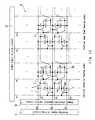
- FIG. 3 is a circuit configuration diagram of the display apparatus of the first embodiment according to the present invention.
- FIG. 4 shows plan views of a pixel layout of a display apparatus of a second embodiment according to the present invention.
- FIG. 5 is a circuit configuration diagram of the display apparatus of the second embodiment according to the present invention.
- FIG. 6A is a waveform diagram of an odd-numbered frame, illustrating a method of driving the display apparatus of the second embodiment according to the present invention by dot inversion driving.
- FIG. 6B is a waveform diagram of an even-numbered frame, illustrating a method of driving the display apparatus of the second embodiment according to the present invention by dot inversion driving.
- FIG. 7A is a waveform diagram of an odd-numbered frame, illustrating a method of driving the display apparatus of the second embodiment according to the present invention by column inversion driving.
- FIG. 7B is a waveform diagram of an even-numbered frame, illustrating a method of driving the display apparatus of the second embodiment according to the present invention by column inversion driving.
- FIG. 8 is a circuit diagram of one pixel of a display apparatus of a fourth embodiment according to the present invention.
- FIG. 9 shows plan views of a pixel layout of the display apparatus of the fourth embodiment according to the present invention.
- FIG. 10 is a cross-sectional view taken along a line A-A′ in FIG. 9 .
- FIG. 11 is a circuit configuration diagram of the display apparatus of the fourth embodiment according to the present invention.
- FIG. 12 shows plan views of a pixel layout of a display apparatus of a fifth embodiment according to the present invention.
- FIG. 13 is a circuit configuration diagram of the display apparatus of the fifth embodiment according to the present invention.
- FIG. 14 is a circuit diagram of one pixel of a display apparatus of the prior art and that of the first embodiment according to the present invention.
- FIG. 15 is a waveform diagram illustrating a method for driving a display apparatus of the prior art and that of the first embodiment according to the present invention.
- FIG. 16A shows a polarity pattern of pixels and a scanning signal waveform in a field inversion system.
- FIG. 16B shows a polarity pattern of pixels and a scanning signal waveform in a line inversion system.
- FIG. 16C shows a polarity pattern of pixels and a scanning signal waveform in a column inversion system.
- FIG. 16D shows a polarity pattern of pixels and a scanning signal waveform in a dot inversion system.
- FIG. 17 is a waveform diagram illustrating that a recharge voltage is different between portions close to feeding ends and a portion away therefrom.
- FIG. 18 is a view illustrating the relationship of the magnitude of a recharge voltage.
- FIG. 19A shows an example of a method for providing a distribution of ⁇ in a screen.
- FIG. 19B shows an example of a method for providing a distribution of ⁇ in a screen.
- FIG. 19C shows an example of a method for providing a distribution of ⁇ in a screen.
- FIG. 19D shows an example of a method for providing a distribution of ⁇ in a screen.
- FIG. 20A shows an example of a method for providing a distribution of ⁇ in a screen.
- FIG. 20B shows an example of a method for providing a distribution of ⁇ in a screen.
- FIG. 20C shows an example of a method for providing a distribution of ⁇ in a screen.
- FIG. 20D shows an example of a method for providing a distribution of ⁇ in a screen.
- FIG. 21 is a model circuit diagram for considering the optimum distribution of ⁇ and ⁇ .
- FIG. 22 is a circuit diagram of the model circuit in FIG. 21 on a constituent element level.
- FIG. 23 is a graph showing changes in a voltage with time at each nodal point in the model circuit in FIG. 21 .
- FIG. 24 is a graph showing a distribution of a recharge voltage in a screen obtained by model calculation.
- FIG. 25A is a graph showing another example of a method for providing a distribution of ⁇ in a screen.
- FIG. 25B is a graph showing another example of a method for providing a distribution of ⁇ in a screen.
- FIG. 26A is a view showing a relationship between an example of a method for feeding a scanning electrode and a common electrode and a recharge voltage.
- FIG. 26B is a view showing a relationship between an example of a method for feeding a scanning electrode and a common electrode and a recharge voltage.
- FIG. 26C is a view showing a relationship between an example of a method for feeding a scanning electrode and a common electrode and a recharge voltage.
- FIG. 26D is a view showing a relationship between an example of a method for feeding a scanning electrode and a common electrode and a recharge voltage.
- FIG. 26E is a view showing a relationship between an example of a method for feeding a scanning electrode and a common electrode and a recharge voltage.
- FIG. 26 E′ is a view showing a relationship between an example of a method for feeding a scanning electrode and a common electrode and a recharge voltage.
- FIG. 27 is a circuit diagram of one pixel in another example of a display apparatus of the present invention.
- FIG. 28A is a waveform diagram of an odd-numbered frame, illustrating a method for driving a display apparatus of another embodiment according to the present invention.
- FIG. 28B is a waveform diagram of an even-numbered frame, illustrating a method for driving a display apparatus of another embodiment according to the present invention.
- FIG. 29A is a waveform diagram of an odd-numbered frame, illustrating another method for driving a display apparatus of another embodiment according to the present invention.
- FIG. 29B is a waveform diagram of an even-numbered frame, illustrating another method for driving a display apparatus of another embodiment according to the present invention.
- FIG. 30 is a view illustrating a relationship in magnitude of a recharge voltage in a p-channel TFT.
- FIG. 31 is a pixel constituent diagram in the case where the present invention is applied to a display apparatus using an organic electroluminescence element.
- FIG. 33A is a view showing an optimum distribution of C st and C gd in a display region obtained by simulation.
- FIG. 33B is a view showing an optimum distribution of C st and C gd in a display region obtained by simulation.
- FIG. 33C is a view showing an optimum distribution of C st and C gd in a display region obtained by simulation.
- FIG. 33D is view showing an optimum distribution of C st and C gd in a display region obtained by simulation.
- a scanning signal driving signal applied to a scanning electrode
- a common electrode control signal are supplied from both sides of a screen. Portions close to feeding ends of scanning electrodes (and common electrodes) in a screen, i.e., both end portions of a screen, will be referred to as “portions close to feeding ends”, and the center of the screen will be referred to as “a portion away from the feeding ends”.
- a potential is shifted from V gon to V goff after a scanning electrode is selected in FIG. 15 .
- a voltage is changed rapidly, whereas in the portion away from the feeding ends, a waveform is distorted due to a CR time constant of the scanning electrode, and the movement of a potential becomes smooth (it is assumed that the movement of the potential of the scanning electrode will be completed substantially by the time V c changes from V c ( ⁇ ) to V coff ).
- the waveforms of the potential of the scanning electrode in the portions close to the feeding ends and the portion away therefrom are drawn as represented by V g in FIG. 17 .
- the potential V d of a pixel electrode is substantially equal to a video signal voltage V sig (+) or V sig ( ⁇ ) at a time of completion of charging ( FIG. 17 shows the case of V sig (+)); however, the potential V d of the pixel electrode fluctuates along with changes in V g due to the capacitive coupling by C gd of the circuit in FIG. 14.
- a change amount ⁇ V a of V d involved in capacitive coupling when V g changes from V gon to V goff is represented by the following Formula (15) irrespective of a distance from the feeding ends.
- the voltage change amount ⁇ V a will be referred to as a feedthrough. This voltage value is substantially the same value irrespective of the polarity of a video signal.
- a TFT is not turned OFF immediately when the potential of the scanning electrode falls, and the TFT is turned OFF when the potential of the scanning electrode passes a switching threshold value (potential higher than the potential of the video signal electrode by a threshold voltage) (the TFT is turned OFF by the time when the potential of the video signal electrode starts shifting toward a scanning period voltage).
- a current flows through the TFT so as to compensate for the potential difference between the video signal electrode-pixel electrode (source-drain of the TFT) generated due to a feedthrough during a finite period (represented by T o or T e in FIG. 17 ) from a time when the scanning electrode potential starts falling to a time when the scanning electrode potential passes the switching threshold value.
- FIG. 17 also shows a state of a change in the pixel electrode potential V d .
- the waveform of V g becomes smoother with increased distance from the feeding ends of the scanning signal driving circuit, and a time required for the TFT to be turned OFF becomes long. Therefore, ⁇ V b is increased with a distance from the feeding ends.
- a current flowing through the TFT will be referred to as a recharge current, and a voltage difference ⁇ V b caused by this will be referred to as a recharge voltage.
- the above-mentioned switching threshold value becomes different between an even-numbered frame (the case where a video signal with a positive polarity is charged) and an odd-numbered frame (the case where a video signal with a negative polarity is charged).
- the level of the switching threshold value when the potential of the scanning electrode shifts from V gon to V goff is drawn with respect to a positive polarity and a negative polarity as shown in FIG. 18 . Based on this, regarding the portions close to the feeding ends and the portion away therefrom, a time required for the TFT to be turned OFF, i.e., a period (corresponding to To or Te) for a recharge to be generated is represented for each polarity as in a bar graph.
- the length of a bar graph substantially corresponds to the magnitude of a recharge current, i.e., the magnitude of a recharge voltage. Therefore, assuming that recharge voltages in the case of a positive polarity and a negative polarity in the portions close to the feeding ends are represented by ⁇ V b (O, +) and ⁇ V b (O), and recharge voltages in the case of a positive polarity and a negative polarity in the portion away from the feeding ends are represented by ⁇ V b (E, +) and ⁇ V b (E), it is understood that there is the following (Formula 16) relationship.
- the falling waveform of the potential of the scanning electrode is set to be the same between the even-numbered frame and the odd-numbered frame for simplicity, the falling waveform may not necessarily be the same.
- nonlinearity a source-drain capacitance or a gate-drain capacitance when the TFT is in an ON state becomes larger than that when the TFT is in an OFF state
- an apparent capacitance becomes larger when the video signal has a negative polarity.
- the CR time constant of the falling of the potential of the scanning electrode becomes large, and falling may become slow.
- the relationship of (Formula 16) still holds.
- V do (O, +), V do (O), and V do ,(E, +), V do (E) of the retention potential of the pixel electrode in the portions close to and the portion away from the feeding ends can be represented by (Formula 17) with the above-mentioned effect of a recharge added to (Formula 12).
- V do ( O, + ) V sig (+) ⁇ st ⁇ V c (+) ⁇ gd ⁇ V gon + ⁇ V b ( O, + )
- V do ( O ) V sig ( ⁇ ) ⁇ st ⁇ V c ( ⁇ ) ⁇ gd ⁇ V gon + ⁇ V b ( O )
- V do ( E, + ) V sig (+) ⁇ st ⁇ V c (+) ⁇ gd ⁇ V gon + ⁇ V b ( E, + )
- V do ( E ) V sig ( ⁇ ) ⁇ st ⁇ V c ( ⁇ ) ⁇ gd ⁇ V gon + ⁇ V b ( E ) (Formula 17)
- ⁇ V cc and V cp are given by the following (Formula 19).
- the DC average level V dc (O) and V dc (E) given by the first and third formulae of (Formula 18) represent voltage values that eliminate flickering. More specifically, if the potential of the counter electrode is matched with the voltage values represented by the first and third formulae of (Formula 18), a time average value of a voltage applied to liquid crystal becomes 0, whereby flickering is eliminated. However, because of (Formula 18) and (Formula 16), the relationship represented by the following (Formula 20) is obtained, and the DC average level has different values in a screen (the DC average level is larger in the portion away from the feeding ends than in the portions close thereto). Therefore, it is impossible to eliminate flickering simultaneously across the entire screen.
- V dc ( E ) ⁇ V dc ( O ) [ ⁇ V b ( E , +)+ ⁇ V b ( E )]/2 ⁇ [ ⁇ V b ( O , +)+ ⁇ V b ( O )]/2>0 (Formula 20)
- V eff given by the second and fourth formulae of (Formula 17) corresponds to an effective value of a voltage applied to liquid crystal, and the liquid crystal exhibits a brightness (transmittance) corresponding to the effective value.
- the relationship represented by the following (Formula 21) is obtained, and the effective value of a voltage applied to liquid crystal also has a distribution (gradient) (the effective value is smaller in the portion away from the feeding ends than in the portions close thereto) across a screen.
- V eff ( E ) ⁇ V eff ( O ) [ ⁇ V b ( E, + ) ⁇ V b ( E )]/2 ⁇ [ ⁇ V b ( O, + ) ⁇ V b ( O )]/2 ⁇ 0 (Formula 21)
- an influence by the fluctuation in the potential of the common electrode is not negligible. More specifically, when the potential of the scanning electrode changes from V gon to V goff , the potential of the pixel electrode decreases due to a feedthrough. Simultaneously with this, the potential of the common electrode also decreases due to the capacitive coupling between the scanning electrode and the common electrode created by C gd and C st in FIG. 14 . The potential decrease is small in the portions close to the feeding ends of the common electrode, whereas it is large in the portion away from the feeding ends of the common electrode. When the potential of the common electrode decreases, the potential of the pixel electrode further decreases along therewith.
- ⁇ st and ⁇ gd are not constant in a screen (more specifically, at least one of C gd , C st , and C lc is not constant). It is assumed that ⁇ st and ⁇ gd in portions close to the feeding ends are ⁇ st (O) and ⁇ gd (O), and ⁇ st and ⁇ gd in a portion away from the feeding ends are ⁇ st (E) and ⁇ gd (E).
- O denotes the portions close to the feeding ends
- E denotes a portion away from the feeding ends.
- ⁇ is smaller in the portion away from the feeding ends in a screen, compared with the portions close thereto.
- ⁇ is larger in the portion away from the feeding ends in a screen, compared with the portions close thereto.
- both the necessary conditions [1] and [2] are satisfied.
- a video of high quality without flickering and a brightness gradient can be obtained without adding an excess signal processing circuit for correcting a video signal ahead of time, so that both low cost and high quality can be satisfied.
- ⁇ and ⁇ are set to be different values between the portions close to the feeding ends and the portion away therefrom, it is required to change these values independently. Therefore, it is desirable that ⁇ st and ⁇ gd are varied by setting at least two of capacitance values C st , C gd , and C lc . (in other words, capacitance values constituting C tot ) contributing to ⁇ st and ⁇ gd between the portions close to the feeding ends and the portion away therefrom.
- C gd and C lc are set to be constant, and only C st is set to have different values between the portions close to the feeding ends (the value of C st is assumed to be C st (O)) and the portion away therefrom (the value of C st is assumed to be C st (E)) to satisfy C st (O) ⁇ C st (E), ⁇ gd (O)> ⁇ gd (E) and ⁇ st (O) ⁇ st (E) are satisfied according to (Formula 14).
- FIG. 19 shows some examples regarding ⁇
- FIG. 20 shows some examples regarding ⁇
- the horizontal axis represents a horizontal position in a screen
- the vertical axis represents a value of ⁇ or ⁇ .
- O, E, and M on the horizontal axis represent a portion close to the feeding ends, a portion away from the feeding ends, and a portion in the middle therebetween in terms of distance, respectively.
- a pattern that changes linearly can be considered most easily.
- a non-linear change also may be considered.
- a change in stages also may be considered.
- a combination of a constant portion and a portion with a slope also may be considered.
- the values of ⁇ and ⁇ in the portion close to the feeding ends and in the portion away from the feeding ends satisfy (Formula 31) and (Formula 29).
- the effects of the present invention can be obtained.
- ⁇ represents an upward convex trend between the portion close to the feeding ends and the portion away therefrom, and ⁇ represents a downward convex trend between the portion close to the feeding ends and the portion away therefrom. The reason for this will be described below.
- FIG. 21 shows scanning electrodes schematically, using 5-stage RC circuits, where the total capacitance between the portion close to the feeding ends and the portion away therefrom is represented as C, and the resistance thereof is represented as R. This assumes that a region between the portion close to the feeding ends of the scanning electrodes and the portion away therefrom is divided equally into five sections, and each of the sections represented by a unit RC circuit as shown in FIG. 22 is connected to each other.
- V g O Assuming that the length between the portion close to the feeding ends of the scanning electrodes and the portion away therefrom is L, node potentials V g O, V g 1 , V g 2 , V g 3 , V g 4 , V g 5 , from the feeding ends of 0 (portion close to the feeding ends), L/10, 3L/10, L/2, 7L/10, 9L/10, and L (portion away from the feeding ends).
- the portion close to the feeding ends is supplied with a voltage by a scanning signal driving circuit.
- V g O is a supply voltage of the scanning signal driving circuit
- R g is an internal impedance of the scanning signal driving circuit.
- FIGS. 19 and 20 show the case assuming that a voltage is supplied from both sides. Since the graphs in FIGS. 19 and 20 are symmetrical, only the left half or right half may be considered. In the case of the circuit model in FIG. 21 , only the left half of FIG. 19 or 20 is considered.
- FIG. 23 shows the results obtained by actually conducting calculation of numerical values.
- the horizontal axis is normalized with CR.
- C tot C gd +C gs +C lc .
- I ds is a source-drain current of a TFT, which is represented by (Formula 33) when ideal MOS characteristics are assumed.
- V do V s ⁇ (C gd /C tot )(V gon ⁇ V goff )(V gon ⁇ V goff )
- V do V s ⁇ (C gd /C tot )(V gon ⁇ V goff )
- V t 2 V
- k b 6 ⁇ 10 ⁇ 9 A/V 2 , as an example.
- a horizontal axis shows values normalized assuming that the portion close to the feeding ends is “0”, and the portion away from the feeding ends is “1”.
- a vertical axis also shows values normalized assuming that ⁇ V b at the portion away from the feeding ends is “1”.
- a distribution of a recharge voltage has an upward convex shape.
- the distribution of a DC average level of a pixel electrode and a liquid crystal application voltage effective value generated by the distribution of the recharge voltage also has a shape as shown in FIG. 24 (in the liquid crystal application voltage effective value, as is presumed from the fact that the right side of (Formula 21) becomes negative, a graph of FIG. 24 inverted upside down can be obtained.
- the DC average level the right side of (Formula 20) is positive, so that a graph is not inverted upside down).
- the distributions of ⁇ and ⁇ for correcting flickering (caused by the distribution of a DC average level) and a brightness gradient (caused by the distribution of a liquid crystal application voltage effective value) has a shape similar to that in FIG. 24 . More specifically, it is desirable that ⁇ is set to be as shown in FIG. 19B , and ⁇ is set to be as shown in FIG. 20B ( FIGS. 19D and 20D may be possible).
- an intermediate position in the middle in terms of a distance between the portion close to the feeding ends and the portion away therefrom.
- values of ⁇ and ⁇ at the portion close to the feeding ends are ⁇ (O) and ⁇ (O)
- the values thereof at the portion away from the feeding ends are ⁇ (E) and ⁇ (E)
- the values thereof at an intermediate position are ⁇ (M) and ⁇ (M), as shown in FIGS.
- the first formula of (Formula 34) is a conditional expression regarding flickering
- the second formula is a conditional expression regarding a brightness gradient.
- V cp of (Formula 19) A supplementary description will be made with respect to V cp of (Formula 19). If the third term regarding recharge is ignored since it is very small, and ⁇ st V cp is assumed to be negative in the formula regarding V eff of (Formula 18) and (Formula 23), an effective value of a voltage applied to liquid crystal becomes a value larger than a video signal amplitude [V sig (+) ⁇ V sig ( ⁇ )]/2.
- a voltage e.g., 10 to 15 V
- a video signal driving IC with a low withstand voltage e.g., about 5 V
- the scanning electrodes supply power from both sides, and the common electrodes supply a power from one side.
- the scanning electrodes supply power from one side, and the common electrodes supply a power from both sides.
- the scanning electrodes and the common electrodes supply power from one side (from the same side).
- the scanning electrodes and the common electrodes supply power from one side (from different sides).
- power may be supplied alternately from both sides of every other line, and power may be supplied from the left side in the upper half of a screen and from the right side in the lower half thereof.
- FIGS. 26A to 26 E show a predicted in-plane distribution (distribution in a horizontal direction) representing how a recharge voltage ⁇ V b is generated.
- G represents a scanning electrode
- C represents a common electrode.
- a portion with a square mark ( ⁇ ) represents a feeding end.
- a curve represented by a broken line shows a recharge voltage in the case where fluctuations in a potential of the common electrode are not considered, and a curve represented by a solid line shows a recharge voltage in the case where fluctuations in a potential of the common electrode are considered.
- a recharge voltage exhibits an arched curve when the scanning electrode is supplied with a power from both sides ((A), (B)), and exhibits a semi-arched curve when the scanning electrode is supplied with a power from one side ((C), (D), (E)).
- ⁇ V b is loaded by the corresponding amount. The loaded amount at this time becomes small at the portion close to the feeding ends of the common electrode, and becomes large at the portion away from the feeding ends.
- (E) due to the ⁇ V b distribution generated only by the scanning electrode and the amount loaded depending upon the effect of fluctuations in a potential of the common electrode, as shown in FIG.
- portions close to the feeding ends end portions of a screen to which at least one of a scanning electrode and a common electrode is supplied with a power
- portions close to the feeding ends More specifically, in all the cases excluding (D), both ends of the screen become “portions close to the feeding ends” (represented by a mark “O” in FIG. 26 ). In only (D), only one end portion becomes a “portion close to the feeding ends”. In the cases other than (D), the vicinity of the center of the screen will be referred to as a “portion away from the feeding ends (represented by a mark “E”).
- the end portion not supplied with a power becomes a “portion away from the feeding ends”.
- the position represented by a mark “M” in the figure is a portion corresponding to the middle between the “portion close to the feeding ends” and the “portion away from the feeding ends” in terms of a distance.
- a certain value ( ⁇ , ⁇ , etc.) is “larger (smaller) in a portion away from the feeding ends, compared with the portions dose to the feeding ends”, this means that a value of the “portion away from the feeding ends” is larger (smaller) than the value of at least one of a plurality of “portions close to the feeding ends”.
- the first and second formulae of (Formula 16) can be understood easily if V b (O, +), V b (O, ⁇ ), and V b (E, +), V b (E, ⁇ ) are replaced by V b in FIGS. 26A to 26 E′.
- the third formula as is understood from FIG. 18 , if it is considered that a recharge voltage is much larger in the case of negative charge than in the case of positive charge, a magnitude correlation between V b (O, +) ⁇ V b (O, ⁇ ) and V b (E, +) ⁇ V b (E, ⁇ ) may be considered to be the same as that between ⁇ V b (O, ⁇ ) and ⁇ V b (E, ⁇ ). It is considered that the third formula also holds since the second formula holds.
- curves of ⁇ V b in FIGS. 26A to 26 E′ have an upward convex shape. Therefore, what is described in (Principle 2 of the present invention: Optimum distribution of ⁇ and ⁇ ) is fully applicable.
- each pixel having the configuration in FIG. 14 the storage capacitance of each pixel also is connected to wiring other than a common electrode.
- the storage capacitance may be connected to a scanning electrode (in this figure, an example of the previous stage) other than the stage concerned.
- V g (n ⁇ 1) the potential of a scanning electrode of the previous stage
- C st 2 the formula of conservation of charge corresponding to (Formula 11) is given by (Formula 36).
- the values of ⁇ st and ⁇ gd are made different by making the value of C st 2 different between the portion close to the feeding ends and the portion away from the feeding ends, whereby the effects of the present invention are obtained.
- connection destination of C st 2 is a scanning electrode in the previous stage, that in a second from the previous stage, that in a third from the previous stage, that in a second from the subsequent stage, that in a third from the subsequent stage, or the like, the same effects can be obtained.
- C tot is further generalized and considered to be a “total of the entire capacitance connected electrically to pixel electrodes”, including FIGS. 14 and 27 , the description and supplementary items regarding the principle of the present invention are all applicable.
- FIG. 1 is a plan view showing a pixel layout of a display apparatus of the first embodiment according to the present invention.
- FIG. 2 is a cross-sectional view taken along a line A-A′ in FIG. 1 .
- reference numerals 11 and 12 denote substrates made of glass or the like.
- Reference numeral 11 denotes an array substrate on which thin film transistors 3 (also called TFTs or switching elements) and electrodes connected thereto are formed
- reference numeral 12 denotes a counter substrate opposing the array substrate.
- Liquid crystal 13 is interposed between two substrates as a display medium, and both ends of the substrates are sealed with a seal 17 .
- Reference numerals 14 and 15 denote polarizing plates for conducting a polarization display, and 19 denotes a color filter for conducting a color display. Although the color filter 19 is formed on the counter substrate 12 side, it may be formed on the array substrate 11 side.
- Scanning electrodes 1 and common electrodes 4 are formed of a first conductive layer on the array substrate 11 , and an insulating film 18 covers these electrodes.
- a pixel electrode 5 is formed of a second conductive layer on the insulating film 18 . As shown in FIG. 2 , a part of the pixel electrode overlaps the common electrode 4 .
- An overlapping portion with the common electrode 4 constitutes a storage capacitor 7 (i.e., common electrode-pixel electrode capacitance C st ).
- an overlapping portion of the pixel electrode 5 and the scanning electrode 1 constitutes a scanning electrode-pixel electrode capacitance C gd .
- a transparent electrode 20 is formed on the counter substrate 12 .
- the transparent electrode 20 and the pixel electrode 5 oppose each other via liquid crystal 13 as a display medium, thereby forming a liquid crystal capacitance C lc .
- liquid crystal is TN (twisted nematic) liquid crystal.
- the thin film transistor 3 is composed of a semiconductor portion 9 and three electrodes. Gate electrodes are connected to the scanning electrodes 1 , source electrodes are connected to video signal electrodes 2 , and drain electrodes are connected to pixel electrodes 5 .
- FIG. 3 is a circuit configuration diagram of a display apparatus of the first embodiment according to the present invention.
- a common electrode-pixel electrode capacitance C st There are provided a common electrode-pixel electrode capacitance C st , a scanning electrode-pixel electrode capacitance C gd , and a liquid crystal capacitance C lc in one pixel so as to correspond to FIGS. 1 and 2 .
- the circuit configuration in FIG. 3 is the same as that in FIG. 14 .
- Such pixels are arranged in a matrix, whereby a display apparatus is constituted.
- the video signal electrodes 2 are connected to a video signal driving circuit 22
- the scanning electrodes 1 are connected to the scanning signal driving circuit 21
- the common electrodes 4 are connected to a common electrode potential control circuit 26 .
- Reference numeral 23 denotes a display element excluding the driving circuits.
- FIG. 3 portions close to feeding ends and a portion away from the feeding ends are shown.
- a pixel layout in each portion is as shown in FIG. 1 .
- the display apparatus of the present embodiment is characterized in that C st and C gd have different shapes between the portion close to the feeding ends and the portion away therefrom, and a capacitance value itself also is different (area of the capacitor is different). Because of this, as described in (Description 1 of the principle of the present invention: Principle of a reduction in a brightness gradient/flickering), a brightness gradient and flickering can be reduced.
- the video signal driving circuit is capable of applying two kinds of video signals with different polarities (i.e., positive and negative video signals based on the potential of the counter electrode, corresponding to V sig (+) and V sig ( ⁇ ) in FIG. 15 ) to video signal electrodes in accordance with a display period.
- the scanning signal driving circuit is capable of applying an output potential level with at least two values (V gon and V goff in FIG. 15 ).
- the common electrode potential control circuit is capable of applying an output potential level with at least two values (V c (+) and V c ( ⁇ ) in FIG. 15 ).
- FIGS. 33A to 33 D the results obtained from simulation conducted by applying specific numerical values to parameters such as a capacitance in the present embodiment are shown in FIGS. 33A to 33 D.
- an equivalent circuit of the entire display region is composed with a circuit simulator, and a DC average level (V dc ) and a liquid crystal application voltage effective value (V eff ) at each position in the display region are calculated.
- V dc DC average level
- V eff liquid crystal application voltage effective value
- a curve marked with “no capacitance gradient” in each figure represents calculated results in the case where a distribution in a display region is not given to C st , C gd , or C lc .
- C st 0.7 pF
- C gd 0.07 pF
- C lc 0.75 pF over the entire display region.
- FIG. 33A shows a state of distribution of C st
- FIG. 33B shows a state of distribution of C gd (“normalized horizontal position” on the horizontal axis refers to a value obtained by normalizing a distance from the left end of a display region by a display region width, and the left end and the right end correspond to “0” and “1”).
- FIGS. 33C and 33D show the results for a DC average level and a liquid crystal application voltage effective value.
- C gd is allowed to have a gradient of 0.070 pF (eft end) to 0.082 pF (right end) as in FIG. 33B , a DC average level and a liquid crystal application voltage effective value become almost flat as in FIG. 33C or 33 D (a distribution width is within 10 mV in any case).
- Embodiment 2 of the present invention the configuration that reduces horizontal crosstalk and lowers a voltage of a video signal driving circuit IC will be described with reference to FIGS. 4 and 5 .
- FIG. 4 is a plan view showing a pixel layout of a display apparatus of the second embodiment according to the present invention.
- the configuration in FIG. 4 basically follows the pixel layout in FIG. 1 .
- pixels are inverted in the vertical direction per column.
- a common electrode 4 is disposed in the middle between two scanning electrodes 1 .
- An insulating film 18 (not shown) is interposed between the pixel electrode and the common electrode to form a storage capacitor 7 (C st ).
- FIG. 5 is a circuit configuration diagram of a display apparatus of the second Embodiment according to the present invention. Basically, this also is the same as that in FIG. 3 . However, pixels are inverted in the vertical direction per column, corresponding to the layout in FIG. 4 . What is important here is that storage capacitance connected to (a plurality of) pixel electrodes of pixels belonging to one scanning electrode (e.g., G 1 ), (ON/OFF of which is controlled by the scanning electrode G 1 ), are connected to two common electrodes (C 0 and C 1 ) that are the other connection destinations.
- G 1 scanning electrode
- C 0 and C 1 common electrodes
- the circuit configuration of the second embodiment also is characterized in that pixels belonging to one scanning electrode (e.g., G 1 ) are present in different stages between the even-number column and the odd-numbered column (note: this is not necessarily a required configuration of the present invention).
- dot inversion driving and column inversion driving also can be adopted, as well as line inversion driving (in the first embodiment, only line inversion or field inversion is adopted). This will be described with reference to FIGS. 5 , 6 A, and 6 B, exemplifying dot inversion.
- FIGS. 6A and 6B are waveform diagrams of an odd-number frame and an even-number frame for illustrating a method for driving a display apparatus of the second embodiment according to the present invention by dot inversion driving.
- the case will be considered in which signals with different polarities are applied to video signal electrodes S 1 (and S 3 , S 5 , . . . , S n , . . . ) and S 2 (and S 4 , S 6 , . . . , S n+1 , . . . ) in an odd-number frame as shown in FIG. 6 A.
- a positive signal V sig (+) and a negative signal V sig ( ⁇ ) are applied to S 1 and S 2 in FIG. 5 , respectively.
- an upper pixel of G 1 (referred to as a “pixel P”) is in an ON state
- a column belonging to S 2 (more exactly, a column belonging to a video signal electrode including S 2 to which a negative video signal is applied)
- a lower pixel of G 1 (referred to as a “pixel Q”) is in an ON state.
- the common electrodes that are connection destinations of storage capacitance of the pixels P and Q are C 0 and C l , respectively (these electrodes will be referred to as the first common electrode and the second common electrode, based on G 1 ).
- These electrodes are separate ones, so that they can be set at different potentials, i.e, C 0 (first common electrode) is set to be V c (+) (corresponding to the state where the pixel P is charged positively), and C 1 (second common electrode) is set to be V c ( ⁇ ) (corresponding to the state where the pixel P is charged negatively).
- FIG. 15 which shows that the effect of an increase in an amplitude of a pixel electrode potential as described in the Background Art with reference to FIGS. 14 and 15 can be obtained.
- G 1 is selected.
- G 0 or G 2 is selected is considered similarly, it is understood that the potential waveform of each common electrode should be set as shown in FIG. 6 A. This also applies to the even-numbered frame shown in FIG. 6B , in which only the polarities of signals of a video signal electrode and a common electrode are reversed.
- dot inversion or column inversion driving which is a driving method advantageous with respect to horizontal crosstalk, is adopted, and the effect of an increase in an amplitude of a pixel electrode retention potential can be obtained.
- the reduction in horizontal crosstalk and the decrease in a voltage of a video signal driving circuit IC can be achieved. More specifically, the second object among the previously described two objects can be achieved.
- the effect of an increase in an amplitude of a pixel electrode retention potential as described in JP 5(1993)-143021 can be obtained with dot inversion driving or column inversion driving in the configurations of FIGS. 4 and 5 .
- FIG. 4 shows the case where C st (O) ⁇ C st (E) and C gd (O) ⁇ C gd (E).
- the video signal driving circuit be designed for dot inversion or column inversion. More specifically, it is desirable that two kinds of video signals with different polarities can be applied simultaneously to a plurality of video signal electrodes, and for each video signal electrode, two kinds of video signals with different polarities can be applied in accordance with a display period (depending upon whether a frame is an odd-number frame or an even-number frame).
- the number of common electrodes that are the other connection destinations of storage capacitance connected to pixel electrodes belonging to the scanning electrode is two (first and second common electrodes in the above description).
- the number of common electrodes to be connected is not necessarily two, and it may be three or more. However, if there are provided two common electrodes in accordance with the polarity of a video signal, driving can be conducted most effectively at timings in FIGS. 6 A and 6 B, or FIGS. 7A and 7B , which is desirable.
- pixels in an even-number column and pixels in an odd-number column are completely symmetrical.
- capacitance values (C gd , C st , and the like) of these pixels may be made different between the even-number column and the odd-number column.
- signals with two polarities are applied simultaneously to a plurality of scanning electrodes
- signals with opposite polarities are applied alternately on the column basis (more specifically, alternately between an even-number column and an odd-number column) in dot inversion and column inversion.
- each polarity may be arranged at every other columns or at random.
- pixels corresponding to two polarities are inverted in the vertical direction.
- the present invention is not limited thereto. More specifically, there may be a method for changing only the connection destinations (common electrodes) of storage capacitance in accordance with the polarity of a video signal electrode in the configuration shown in FIG. 1 or 3 . In this case, in addition to the problem of asymmetry of the configuration, wiring for connecting storage capacitance crosses other scanning electrodes in a layout, which generates an excess capacitance, leading to crosstalk. Thus, this is not desirable.
- a display apparatus using liquid crystal in an In Plane Switching (IPS) mode will be described with reference to FIGS. 9 and 10 .
- IPS In Plane Switching
- FIG. 9 is a plan view showing a pixel layout of a display apparatus of the fourth embodiment according to the present invention.
- FIG. 10 is a cross-sectional view taken along a line A-A′ in FIG. 1 .
- reference numerals 11 and 12 denote substrates made of glass or the like.
- Reference numeral 11 denotes an array substrate on which thin film transistors and electrodes connected thereto are formed
- reference numeral 12 denotes a counter substrate opposing the array substrate.
- Liquid crystal 13 is interposed between two substrates, and both ends thereof are sealed with a seal 17 .
- Reference numerals 14 and 15 denote polarizing plates for conducting a polarization display, and 19 denotes a color filter for conducting a color display. Although the color filter is formed on the counter substrate 12 side, it may be formed on the array substrate 11 side.
- scanning electrodes 1 and common electrodes 4 are formed of a first conductive layer, and an insulating film 18 covers these electrodes.
- a pixel electrode 5 is formed of a second conductive layer on the insulating film 18 . As shown in FIG. 10 , the pixel electrode 5 overlaps the scanning electrode 1 of the previous stage. The overlapping portion with the scanning electrode 1 constitutes a storage capacitor 7 (C st ). Furthermore, the overlapping portion of the pixel electrode 5 and the scanning electrode 1 of the stage concerned constitutes a scanning electrode-pixel electrode capacitance C gd .
- the common electrode 4 is provided with a branched portion 4 A.
- the branched portion 4 A opposes the pixel electrode 5 in parallel, and works as a counter electrode for applying an electric field to a liquid crystal layer.
- the capacitance between the pixel electrode 5 and the common electrode 4 constitutes a common electrode-pixel electrode capacitance C lc .
- the capacitance between the pixel electrode 5 and the common electrode 4 includes both a capacitance via the liquid crystal layer and a capacitance formed by both electrodes that overlap each other geometrically. Although it is difficult to calculate the capacitance via the liquid crystal layer by using a mathematical formula or the like, it may be obtained by actual measurement or simulation.
- the thin film transistor 3 is composed of a semiconductor portion 9 and three electrodes. Gate electrodes are connected to the scanning electrodes 1 , source electrodes are connected to video signal electrodes 2 , and drain electrodes are connected to pixel electrodes 5 .
- FIG. 11 shows a circuit configuration of a display apparatus of the present embodiment using liquid crystal in an IPS mode.
- a unit pixel configuration shown in FIG. 8 are arranged in an array.
- the scanning electrodes 1 are supplied with power from a scanning signal driving circuit 21
- the video signal electrodes 2 are supplied with power from a video signal driving circuit 22 .
- V do ⁇ ( - ) ⁇ V sig ⁇ ( - ) - ⁇ lc ⁇ ⁇ ⁇ ⁇ V c ⁇ ( - ) - ⁇ gd ⁇ ⁇ ⁇ ⁇ V gon
- a scanning electrode of the previous stage corresponds to the counter electrode (V f ) in FIG. 3 (and FIG. 14 ), if it is considered that C st is replaced by C lc .
- the scanning electrode of the previous stage has a potential V goff in a non-selection state, when the scanning electrode of the stage concerned is selected. Therefore, it is possible to consider that the scanning electrode of the previous stage is the same as the counter electrode in FIG. 3 . In other words, any electrode having the same potential both during a selection period of the scanning electrode of the stage concerned and during a retention period can be used as a connection destination of C st .
- Such an electrode may be any electrode excluding a common electrode opposing a pixel electrode via a display medium (liquid crystal: capacitance C lc ) and a scanning electrode of the stage concerned.
- a scanning electrode (which may be of the subsequent stage) excluding the scanning electrode of the stage concerned, or a common electrode other than those opposing via C lc is particularly desirable.
- FIG. 12 is a plan view showing a pixel layout of a display apparatus of the fifth embodiment according to the present invention.
- a layout is inverted in the vertical direction on the column basis, in the same way as in the second embodiment in which a reduction in horizontal crosstalk and a decrease in a voltage of a video signal driving circuit IC are realized.
- FIG. 13 is a circuit configuration diagram of the display apparatus of the fifth embodiment according to the present invention. This corresponds to the case where TN liquid crystal is used (i.e., FIG. 5 showing the circuit configuration of the second embodiment).
- ⁇ gd in a portion farthest from the feeding ends of scanning electrodes is assumed to be ⁇ gd (F)
- ⁇ gd (F) it is desirable that there is a position having a value of ⁇ gd larger than ⁇ gd (F) between the portion furthest from the feeding ends of the scanning electrodes and the portion close thereto.
- scanning electrodes are supplied with a power from one side, and the potential of the common electrodes is fixed only on the opposite side, as in FIG. 26 E.
- FIGS. 6A and 6B Exemplary voltage waveforms in the driving method of the present invention are shown in FIGS. 6A and 6B , FIGS. 7A and 7B , or FIG. 15 .
- driving waveforms as in FIGS. 28A , 28 B, 29 A, and 29 B.
- FIGS. 28A and 28B show driving waveforms in the case of driving the circuit with the configuration shown in FIG. 3 or 11 .
- a common electrode potential during a retention period is only one value, i.e., V coff ; however, in the driving waveforms in FIGS. 28A and 28B , a common electrode potential during a retention period is not necessarily one kind, and has two kinds of values, i.e., V c (+) and V c ( ⁇ ).
- ⁇ V c (+) or ⁇ V c ( ⁇ ) also is a value of a potential (in this case, V c (+) or V c ( ⁇ )) of a common electrode to which storage capacitance is connected, at a moment when a pixel is charged, based on a potential (in this case, V coff ) in a retention state.
- FIGS. 29A and 29B show driving waveforms in the case of driving a circuit with the configuration in FIG. 5 or 13 . These driving waveforms are to be compared with those in FIGS. 6A and 6B . Also in this case, a common electrode potential during a retention period is not necessarily one kind, and has two kinds of values, i.e., V c (+) and V c ( ⁇ ).
- a scanning electrode G 1 is selected, and pixel electrodes belonging to a video signal electrode S 1 are charged with a positive signal, and pixel electrodes belonging to a video signal electrode S 2 are charged with a negative signal (the case of an odd-number frame in FIG. 29 A).
- the potentials of common electrodes C 0 and C 1 connected via storage capacitance are V c (+) and V c ( ⁇ ), respectively; however, they are V c ( ⁇ ) and V c (+), respectively, during a retention period.
- any pixel electrode when it is charged with a positive signal, the potential of a common electrode that is a connection destination of storage capacitance always is V c (+) and becomes V c ( ⁇ ) during a retention period.
- V c (+) When a pixel electrode is charged with a negative signal, the potential of a common electrode of a connection destination of storage capacitance always is V c ( ⁇ ) and becomes V c (+) during a retention period.
- FIGS. 7A and 7B In the case of using the driving method in FIGS. 6A and 6B , FIGS. 7A and 7B , or FIG. 15 , three potential levels are required in a common electrode potential control circuit. However, in the case of the present embodiment, only two potential levels are required. Thus, compared with the driving method in FIGS. 6A and 6B , FIGS. 7A and 7B , or FIG. 15 , the configuration of the common electrode potential control circuit can be simplified, and cost can be reduced.
- an n-channel thin film transistor (which is turned on when a gate potential is larger than a threshold voltage, and turned off when a gate potential is smaller than a threshold voltage) has been assumed as a switching element.
- the above description also applies to the case of a switching element of a p-channel TFT (which is turned off when a gate potential is larger than a threshold voltage, and turned on when a gate potential is smaller than a threshold voltage).
- FIG. 30 shows a relationship in magnitude of a recharge voltage corresponding to FIG. 18 .
- the conditions for eliminating a brightness gradient and flickering in this case will be considered.
- the condition for eliminating a brightness gradient the same relationship as that of (Formula 29) is obtained from (Formula 28) and the third formula of (Formula 45).
- the condition for eliminating flickering the right side of (Formula 30) becomes negative from the first and second formulae of (Formula 45).
- ⁇ V gon also is negative, and the same relationship as that of (Formula 31) can be obtained.
- the condition for eliminating a brightness gradient and the condition for eliminating flickering are represented by the same formula, irrespective of whether a thin film transistor is an n-channel type or a p-channel type, and the configuration of the present invention is all applicable.
- one pixel When liquid crystal is driven, one pixel may be charged twice or more in one frame (display period). For example, the following may be conducted: a video signal for conducting a black display is written after a video signal is written in one frame, whereby blurring with respect to animation is improved (generally, after 50 to 99% of a time in one frame has passed after a video signal is written, a video signal for conducting a black display often may be written).
- a video signal for conducting a black display may be written for the purpose of preventing reverse transition.
- a video signal may be written for the purpose of conducting preliminary charging 1H to 2H (1H is a horizontal period) before charging of a pixel is conducted.
- a video signal may be written to a plurality of lines simultaneously (more specifically, the potential of scanning electrodes in a plurality of lines is made V gon simultaneously). For example, this corresponds to the case where a black signal is written to a plurality of lines simultaneously when a black display is conducted.
- preliminary charging may be conducted simultaneously with main charging of the other pixels.
- An optical state of liquid crystal is controlled with an applied voltage (driving with a voltage), whereas an optical state of a self-emitting type diode, laser, electroluminescence material generally is controlled with a current (driving with a current).
- a current driving with a current
- FIG. 31 if a pixel configuration is obtained in which a pixel TFT controls a gate potential of another auxiliary TFT 25 (also referred to as an auxiliary switching element), whereby a current flowing into an organic electroluminescence element 24 is controlled, active matrix type driving is made possible.
- the configuration of the present invention is applicable.
- the sum of a gate-source capacitance and a gate-drain capacitance of the auxiliary TFT 25 may be considered to be C lc .
- ⁇ refers to a difference in a capacitive coupling voltage superimposed on pixel electrodes from common electrodes between the case where the polarity of a video signal is positive and the case where the polarity of a video signal is negative (in other words, a difference between the application of a positive voltage to a display medium and the application of a negative voltage thereto).
- a distribution of a capacitive coupling voltage is varied in a display region between the application of a positive voltage to a display medium and the application of a negative voltage thereto, whereby the effect of eliminating a brightness gradient is obtained.
- a capacitive coupling voltage superimposed on the pixel electrodes is not necessarily from common electrodes. However, in order to adjust the potential freely in synchronization with the scanning electrodes, it is desirable to use common electrodes.
- a method for changing a value in a screen in the present invention basically is realized by setting such a layout intentionally (more specifically, by setting a design mask figure intentionally).
- a design mask figure is created as in the prior art (more specifically, layouts of a pixel P and a pixel Q are designed to be uniform in a screen without giving a difference therebetween), for example, by intentionally shifting mask alignment in the course of production, the effects of the present invention also can be obtained.
- a capacitance value it is easiest to change an overlapping area of two conductive layers (or semiconductor layers) in a capacitance formed by allowing two conductive layers (or semiconductor layers) to sandwich an insulating layer.
- a gap between two conductive layers on a layout is changed by utilizing a capacitance caused by two conductive layers (or semiconductor layers) that are not overlapped with each other in a plane but are close to each other.
- ⁇ st and ⁇ gd may be changed for each line.
- the scanning signal driving circuit supplies a power from the upper side. However, it may supply a power from the lower side, or from upper and lower sides. Furthermore, the scanning signal driving circuit may supply a power alternately to every other column.
- a scanning signal is supplied from the left (or right) side, and a video signal is supplied from the upper (or lower) side.
- the present invention is applicable to a display apparatus in which a scanning signal is supplied from the upper (or lower) side, and a video signal is supplied from the left (or right) side.
- a display apparatus which refers to the entire apparatus including a scanning signal driving circuit and a video signal driving circuit.
- a portion at least including an array substrate, a counter substrate, and liquid crystal, without including a driving circuit particularly is referred to as a “display element”.
- the effects of the present invention can be obtained both in a display apparatus and a display element.
- liquid crystal a liquid crystal other than the above-mentioned TN liquid crystal and IPS liquid crystal may be used.
- VA vertical alignment
- MVA multi-domain VA liquid crystal or other liquid crystal may be used.
- TN twisted nematic liquid crystal
- STN super twisted nematic liquid crystal
- ECB electric field control birefringence type liquid crystal including VA liquid crystal (vertical alignment liquid crystal or homeotropic liquid crystal), homogeneous alignment liquid crystal, and the like, bent liquid crystal, IPS (in-plane switching) liquid crystal, GH (guest-host) liquid crystal, polymer dispersion type liquid crystal, ferroelectric liquid crystal, antiferroelectric liquid crystal, OCB liquid crystal, discotic liquid crystal, and other various modes
- Liquid crystal may be of a normally white type (a transmittance is decreased with an increase in an applied voltage) or a normally black type (a transmittance is increased with an increase in an applied voltage.
- liquid crystal a material whose optical characteristics are changed with an applied voltage may be used.
- electrooptical liquid crystal such as BSO (bismuth silicon oxide) and the like can be used.
- an electrochromic material, a self-emitting diode, laser, electroluminescence material, and the like may be used.
- a DMD (deformable mirror device) and the like may be used. Since liquid crystal is least expensive, it is desirable to use liquid crystal.
- a direct-vision type liquid crystal display panel has been described mainly.
- the present invention also is applicable to a liquid crystal element (including a polycrystalline Si type, a single crystal Si type, SOI (silicon-on-insulator) type, and the like) used in a liquid crystal projector.
- a display apparatus of a TN type configuration (more generally, a configuration in which a pixel electrode and a counter electrode form a parallel plate capacitance with a liquid crystal layer interposed therebetween) has been described.
- a display apparatus with an IPS type configuration (more generally, a configuration in which a common electrode and a pixel electrode are formed on the same substrate, and liquid crystal is operated with an electric field parallel to the substrate) has been described.
- the first to third embodiments i.e., the unit pixel circuit configuration in FIG. 14 may be implemented with an IPS type configuration.
- a common electrode (potential V c (n)) and a counter electrode (potential V f ) only need to be produced separately on a substrate (the counter electrode may be separated on the line basis or column basis).
- the fourth to sixth embodiments i.e., the unit pixel circuit configuration in FIG. 8 may be implemented with a TN-type configuration.
- a counter electrode formed on a substrate on a counter side plays a role as a common electrode.
- a counter electrode is one electrode formed over the entire surface of a display region. Therefore, it is required that the potential takes either V c (+) or V c ( ⁇ ) while the entire screen is scanned.
- V c (+) or V c ( ⁇ ) while the entire screen is scanned.
- the effects of the present invention are obtained similarly.
- a counter electrode is insulated on the line basis with a TN-type configuration
- the potential of the counter electrode in each line can be set separately, and the fourth to sixth embodiments can be implemented as they are.
- a method for varying while keeping common electrodes or a counter electrode at the same potential for example, in the unit pixel circuit configuration in FIGS. 8 and 14 (synchro gate driving method).
- a counter electrode potential V f and a common electrode potential V c (n) are set to be a first potential, and in the case where the video signal is negative, these potentials are set to be a second potential.
- the connection destinations (more specifically, V c (n) and V f ) of C st and C lc in FIG. 14 have the same potentials. Therefore, C st and C lc can be considered merely as a parallel capacitance, and C st +C lc can be considered to be equivalent to C lc in FIG. 8 (C st in FIG. 8 may be 0).
- the above-mentioned first potential may be considered to be V c (+)
- the second potential may be considered to be V c ( ⁇ )
Abstract
Description
V do(−)=V sig(−)−αst ΔV c(−)−αgd ΔV gon
V do(+)=V sig(+)−αst ΔV c(+)−αgd ΔV gon (Formula 12)
ΔV gon =V gon −V goff
ΔV c(+)=V c(+)−V coff
ΔV c(−)=V c(−)−V coff (Formula 13)
αgd =C gd /C tot
αst =C st /C tot
C tot =C gd +C lc +C st (Formula 14)
αgd =C gd /C tot, αst =C st /C tot (Formula 1)
are set to be different values between a portion close to feeding ends in a screen and a portion away therefrom.
γ=αst V cp/2 (Formula 2)
(where V cp =ΔV c(+)−ΔV c(−) (Formula 3))
is set to be smaller in the portion away from the feeding ends in the screen, compared with the portion close thereto.
β=αgd+αst(ΔV cc /ΔV gon) (Formula 4)
(where ΔV gon =V gon −V goff , ΔV cc =[ΔV c(+)+ΔV c(−)]/2 (Formula 5))
is set to be larger in the portion away from the feeding ends in the screen, compared with the portion close thereto.
γ=αst V cp/2 (Formula 2)
(where V cp =ΔV c(+)−ΔV c(−) (Formula 3))
is set to be smaller in the portion away from the feeding ends in the screen, compared with the portion close thereto, and
β=αgd +α st(ΔV cc /ΔV gon) (Formula 4)
(where ΔV gon =V gon −V goff , ΔV cc =[ΔV c(+)+ΔVc(−)]/2 (Formula 5))
is set to be larger in the portion away from the feeding ends in the screen, compared with the portion close thereto.
αgd =C gd /C tot, αst =C st /C tot (Formula 1)
are set to be different values between a portion close to feeding ends in a screen and a portion away therefrom.
(where V cp =ΔV c(+)−ΔV c(−) (Formula 3))
is set to be smaller in the portion away from the feeding ends in the screen, compared with the portion close thereto.
β=αgd+αst(ΔVcc /ΔV gon) (Formula 4)
(where ΔV gon =V gon −V goff , ΔV cc =[ΔV c(+)+ΔVc(−)]/2 (Formula 5))
is set to be larger in the portion away from the feeding ends in the screen, compared with the portion close thereto.
γ=αst V cp/2 (Formula 2)
(where V cp =ΔV c(+)−ΔV c(−) (Formula 3))
is set to be smaller in the portion away from the feeding ends in the screen, compared with the portion close thereto, and
β=αgd +α st(ΔV cc /ΔV gon) (Formula 4)
(where ΔV gon =V gon −V goff , ΔV cc=[ΔVc(+)+ΔV c(−)]/2 (Formula 5))
is set to be larger in the portion away from the feeding ends in the screen, compared with the portion close thereto.
αgd =C gd /C tot, αlc =C lc /C tot (Formula 6)
are set to be different values between a portion close to feeding ends in a screen and a portion away therefrom.
γ=αlc V cp/2 (Formula 7)
(where V cp =ΔV c(+)−ΔV c(−) (Formula 8))
is set to be smaller in the portion away from the feeding ends in the screen, compared with the portion close thereto.
β=αgd+αlc(ΔVcc /ΔV gon) (Formula 9)
(where ΔV gon =V gon −V goff , ΔV cc =[ΔV c(+)+ΔV c(−)]/2 (Formula 10))
is set to be larger in the portion away from the feeding ends in the screen, compared with the portion close thereto.
γ=αlc V cp/2 (Formula 7)
(where V cp =ΔV c(+)−ΔV c(−) (Formula 8))
is set to be smaller in the portion away from the feeding ends in the screen, compared with the portion close thereto, and
β=αgd+αlc(ΔV cc /ΔV gon) (Formula 9)
(where ΔV gon =V gon −V goff , ΔV cc =[ΔV c(+)+ΔV l(−)]/2 (Formula 10))
is set to be larger in the portion away from the feeding ends in the screen, compared with the portion close thereto.
αgd =C gd /C tot, αlc =C lc /C tot (Formula 6)
are set to be different values between a portion close to feeding ends in a screen and a portion away therefrom.
(where V cp =ΔV c(+)−ΔV c(−) (Formula 8))
is set to be smaller in the portion away from the feeding ends in the screen, compared with the portion close thereto.
β=αgd +α lc(ΔV cc /ΔV gon) (Formula 9)
(where ΔV gon =V gon −V goff , ΔV cc =[ΔV c(+)+ΔVc(−)]/2 (Formula 10))
is set to be larger in the portion away from the feeding ends in the screen, compared with the portion close thereto.
γ=αlc V cp/2 (Formula 7)
(where V cp =ΔV c(+)−ΔV c(−) (Formula 8))
is set to be smaller in the portion away from the feeding ends in the screen, compared with the portion close thereto, and
β=αgd+αlc(ΔV cc /ΔV gon) (Formula 9)
(where ΔV gon =V gon −V goff , ΔV cc =[ΔV c(+)+ΔV c(−)]/2 (Formula 10))
is set to be larger in the portion away from the feeding ends in the screen, compared with the portion close thereto.
αgd =C gd /C tot, αst =C st /C tot (Formula 1)
are set to be different values between a portion close to feeding ends in a screen and a portion away therefrom.
αgd =C gd /C tot, αst =C st /C tot (Formula 1)
are set to be different values between a portion close to feeding ends in a screen and a portion away therefrom.
αgd =C gd /C tot, αlc =C lc /C tot (Formula 6)
are set to be different values between a portion close to feeding ends in a screen and a portion away therefrom.
αgd =C gd /C tot, αlc =C lc /C tot (Formula 6)
are set to be different values between a portion close to feeding ends in a screen and a portion away therefrom.
αgd =C gd /C tot (Formula 101)
in a portion furthest from feeding ends of the scanning electrodes in a display region is αgd(F), there is a position where the value of αgd becomes larger than αgd(F) between the portion furthest from the feeding ends of the scanning electrodes in the display region and a portion closest thereto.
ΔV a=−(C gd /C tot)(V gon −V goff)
where C tot =C gd +C lc +C st (Formula 15)
ΔV b(O, +)<ΔV b(E, +)
ΔV b(O)<ΔVb(E)
ΔV b(O, +)−ΔVb(O)>ΔV b(E, +)−ΔV b(E) (Formula 16)
V do(O, +)=V sig(+)−αst ΔV c(+)−αgd ΔV gon +ΔV b(O, +)
V do(O)=V sig(−)−αst ΔV c(−)−αgd ΔV gon +ΔV b(O)
V do(E, +)=V sig(+)−αst ΔV c(+)−αgd ΔV gon +ΔV b(E, +)
V do(E)=V sig(−)−αst ΔV c(−)−αgd ΔV gon +ΔV b(E) (Formula 17)
V dc(E)−V dc(O)=[ΔV b(E, +)+ΔV b(E)]/2−[ΔV b(O, +)+ΔV b(O)]/2>0 (Formula 20)
V eff(E)−Veff(O)=[ΔV b(E, +)−ΔV b(E)]/2−[ΔV b(O, +)−ΔV b(O)]/2<0 (Formula 21)
When the difference ΔVeff of the liquid crystal application voltage effective value at the portions close to the feeding ends and the portion away from the feeding ends is calculated, (Formula 24) holds.
where γ(O) and γ(E) are given by the following (Formula 25):
γ(O)=αst(O)V cp/2
γ(O)=αst(E)V cp/2 (Formula 25)
When the difference ΔVdc of the DC average levels is calculated, the following (Formula 26) holds.
where β(O) and β(E) are given by the following (Formula 27):
β(O)=αgd(O)+αst(O)(ΔV cc /ΔV gon)
β(E)=αgd(E)+αst(E)(ΔV cc /ΔV gon) (Formula 27)
γ(O)>γ(E) (Formula 29)
[β(E)−β(O)]ΔV gon =[ΔV b(E, +)+ΔVb(E, −)−ΔV b(O, +)−ΔV b(O, −)]/2 (Formula 30)
β(O)<β(E) (Formula 31)
Δαgd/Δαst =−C gd/(C gd +C lc) (Formula 47)
Δαgd/Δαst =−C st/(C st +C lc) (Formula 48)
I ds +C tot ·dV d /dt−C gd ·dV g(n)/dt=0 (Formula 32)
Herein, Ctot=Cgd+Cgs+Clc. Furthermore, Ids is a source-drain current of a TFT, which is represented by (Formula 33) when ideal MOS characteristics are assumed.
Herein, k is a constant representing a charge ability of a TFT, and Vt represents a threshold voltage of a TFT. The initial conditions of (Formula 32) are Vd=Vs, Vg(n)=Vgon at t=0. Furthermore, after a sufficient time elapses (t=∞), Vg(n)=Vgoff, a TFT is in an OFF state, and Ids=0 (in the case of the fourth formula of (Formula 33)). Therefore, Vd becomes a constant value (dVd/dt=0(t=∞) is obtained from (Formula 32)). The difference between the value of a final plateau Vdo of Vd obtained by numerical calculation and the value of a final plateau Vdo of Vd in the absence of recharge, i.e., the value of Vdo when Ids=0 always is satisfied in (Formula 32), i.e., Vdo=Vs−(Cgd/Ctot)(Vgon−Vgoff), corresponds to a recharge voltage ΔVb.
β(M)>[β(O)+β(E)]/2
γ(M)<[γ(O)+γ(E)]/2 (Formula 34)
ΔV cc=−(αgd/αst)ΔVgon (Formula 35)
Because of the above, a d.c. voltage component is not supplied between a video signal electrode and a pixel electrode, and unnecessary ions can be suppressed from being generated in liquid crystal and an insulating film. Therefore, stability with time can be enhanced. Since ΔVgon, αgd, and αst are positive, it is desirable that ΔVcc is negative. Even if (Formula 35) is not satisfied, if at least ΔVcc is negative, a voltage difference between a DC average level [Vsig(+)+Vsig(−)]/2 of a video signal and a DC average level Vdc(O) or Vdc(E) of a pixel electrode can be reduced, and the above-mentioned effects can be obtained to some degree.
(
Herein, when a scanning electrode Vg(n) is selected, Vg(n−1) has already been selected. Therefore, the potential is Vgoff. When (Formula 36) is modified, (Formula 37) is obtained.
V do(−)=V sig(−)−αst ΔV c(−)−αgd ΔV gon
V do(+)=V sig(+)−αst ΔV c(+)−αgd ΔV gon (Formula 37)
Herein, ΔVgon, ΔVc(+), and ΔVc(−) are represented by (Formula 13), and αgd and αst are represented by the following (Formula 38):
αgd =C gd /C tot
αst =C st /C tot
C tot =C gd +C lc +C st +C st 2 (Formula 38)
When the above-mentioned results are compared with
Herein, the following is taken into consideration: when a scanning electrode (Vg(n)) is selected, a scanning electrode (Vg(n−1)) of the previous stage has been selected, and the potential has become Vgoff. When (Formula 39) is modified, (Formula 40) is obtained.
where ΔVgon, ΔVc(+), and ΔVc(−) are the same as those in (Formula 13), and αgd and αlc are represented by (Formula 41):
αgd =C gd /C tot
αlc =C lc /C tot
αC tot =C gd +C lc +C st (Formula 41)
This is the formula obtained by changing Vcoff of the second term (the term including Cst) of the right side to Vc(−) or Vc(+) in the second formula of (Formula 11). If the following (Formula 43) is used in place of (Formula 13), (Formula 12) holds as it is.
ΔV gon =V gon −V goff
ΔV c(+)=V c(+)−V c(−)
ΔV c(−)=V c(−)−V c(+) (Formula 43)
More specifically, if ΔVc(+) and ΔVc(−) are read as in (Formula 43), the following discussion (the principles and the like described in (Analysis of the problems of the prior art), (
|ΔV b(O, +)|<|ΔV b(E, +)|
|ΔV b(O, −)|<|ΔV b(E, −)|
|ΔV b(O, +)|−|ΔV b(O, −)|
<|ΔV b(E, +)|−|ΔV b(E, −)| (Formula 44)
ΔV b(O, +)>ΔV b(E, +)
ΔV b(O, −)>ΔV b(E, −)
ΔV b(O, +)−ΔV b(O, −)
>ΔV b(E, +)−ΔV b(E, −) (Formula 45)
Claims (22)
αgd =C gd /C tot, αst =C st /C tot (Formula 1)
αgd =C gd /C tot, αst =C st /C tot (Formula 1)
γ=αst V cp/2 (Formula 2)
(where V cp =ΔV c(+)−ΔV c(−) (Formula 3))
αgd =C gd /C tot, αst =C st /C tot (Formula 1)
β=αgd+αst(ΔV cc /ΔV gon) (Formula 4)
(where ΔV gon =V gon −V goff , ΔV cc =[ΔV c(+)+ΔV c(−)]/2 (Formula 5))
αgd =C gd /C tot, αst =C st /C tot (Formula 1)
γ=αst V cp/2 (Formula 2)
(where V cp =ΔV c(+)−ΔV c(−) (Formula 3))
β=αgd+αst(ΔV cc /ΔV gon) (Formula 4)
(where ΔV gon =V gon −V goff , ΔV cc =[ΔV c(+)+ΔV c(−)]/2 (Formula 5))
αgd =C gd /C tot, αst =C st /C tot (Formula 1)
Applications Claiming Priority (3)
| Application Number | Priority Date | Filing Date | Title |
|---|---|---|---|
| JP2000-181101 | 2000-06-16 | ||
| JP2000181101 | 2000-06-16 | ||
| PCT/JP2001/004918 WO2001096937A1 (en) | 2000-06-16 | 2001-06-11 | Active matrix display device, its driving method, and display element |
Related Child Applications (1)
| Application Number | Title | Priority Date | Filing Date |
|---|---|---|---|
| US09/880,423 Reissue US6731241B2 (en) | 2001-06-13 | 2001-06-13 | Dual-polarization common aperture antenna with rectangular wave-guide fed centered longitudinal slot array and micro-stripline fed air cavity back transverse series slot array |
Publications (2)
| Publication Number | Publication Date |
|---|---|
| US20020154084A1 US20020154084A1 (en) | 2002-10-24 |
| US6963335B2 true US6963335B2 (en) | 2005-11-08 |
Family
ID=18682081
Family Applications (2)
| Application Number | Title | Priority Date | Filing Date |
|---|---|---|---|
| US10/049,583 Ceased US6963335B2 (en) | 2000-06-16 | 2001-06-11 | Active matrix type display apparatus method for driving the same, and display element |
| US11/880,423 Expired - Lifetime USRE41237E1 (en) | 2000-06-16 | 2001-06-11 | Active matrix type display apparatus, method for driving the same, and display element |
Family Applications After (1)
| Application Number | Title | Priority Date | Filing Date |
|---|---|---|---|
| US11/880,423 Expired - Lifetime USRE41237E1 (en) | 2000-06-16 | 2001-06-11 | Active matrix type display apparatus, method for driving the same, and display element |
Country Status (7)
| Country | Link |
|---|---|
| US (2) | US6963335B2 (en) |
| EP (1) | EP1300719B1 (en) |
| JP (2) | JP3723747B2 (en) |
| KR (1) | KR100517530B1 (en) |
| CN (1) | CN1289945C (en) |
| TW (1) | TWI293132B (en) |
| WO (1) | WO2001096937A1 (en) |
Cited By (21)
| Publication number | Priority date | Publication date | Assignee | Title |
|---|---|---|---|---|
| US20040085503A1 (en) * | 2002-10-31 | 2004-05-06 | Lg.Philips Lcd Co., Ltd. | In-plane switching mode liquid crystal display device |
| US20040263743A1 (en) * | 2003-06-27 | 2004-12-30 | Lg.Philips Lcd Co., Ltd. | Liquid crystal display device and method for driving the same |
| US20050139837A1 (en) * | 2003-12-30 | 2005-06-30 | Lg Philips Lcd Co., Ltd. | In-plane switching mode liquid crystal display device |
| US20060145983A1 (en) * | 2004-12-31 | 2006-07-06 | Dong-Hoon Lee | Liquid crystal display device |
| US20080036934A1 (en) * | 2006-08-14 | 2008-02-14 | Yoon-Sung Um | Liquid crystal display and method of driving the same |
| US20080042963A1 (en) * | 2006-07-03 | 2008-02-21 | Epson Imaging Devices Corporation | Liquid crystal device, method of driving liquid crystal device, and electronic apparatus |
| US20080094324A1 (en) * | 2003-08-25 | 2008-04-24 | Texas Instruments Incorporated | Deinterleaving Transpose Circuits in Digital Display Systems |
| US20080136984A1 (en) * | 2006-12-11 | 2008-06-12 | Ryoichi Yokoyama | Liquid crystal display |
| US20090002303A1 (en) * | 2007-05-25 | 2009-01-01 | Innocom Technology (Shenzhen) Co., Ltd. | Liquid crystal display capable of compensating common voltage signal thereof |
| US20090170564A1 (en) * | 2002-03-04 | 2009-07-02 | Sanyo Electric Co., Ltd. | Organic electro luminescense display apparatus and application thereof |
| US20090213148A1 (en) * | 2005-11-29 | 2009-08-27 | Shinji Takasugi | Image display device |
| US20090219237A1 (en) * | 2008-02-29 | 2009-09-03 | Epson Imaging Devices Corporation | Electro-optical device, driving method thereof, and electronic apparatus |
| US20100271359A1 (en) * | 2009-04-22 | 2010-10-28 | Sony Corporation | Liquid crystal display device, and method of driving liquid crystal display device |
| US7907111B2 (en) | 2006-09-26 | 2011-03-15 | Epson Imaging Devices Corporation | Driving circuit, liquid crystal device, electronic apparatus, and method of driving liquid crystal device |
| US20120098807A1 (en) * | 2010-10-22 | 2012-04-26 | Samsung Mobile Display Co., Ltd. | Active level shift driver circuit and liquid crystal display apparatus including the same |
| US20140313113A1 (en) * | 2013-04-22 | 2014-10-23 | Samsung Display Co., Ltd. | Liquid crystal display and driving method thereof |
| US9389188B2 (en) | 2010-12-22 | 2016-07-12 | Koninklijke Philips N.V. | Method and apparatus for testing optical films |
| US20170147119A1 (en) * | 2006-06-09 | 2017-05-25 | Apple Inc. | Touch screen liquid crystal display |
| US10331259B2 (en) | 2004-05-06 | 2019-06-25 | Apple Inc. | Multipoint touchscreen |
| US10409434B2 (en) | 2010-12-22 | 2019-09-10 | Apple Inc. | Integrated touch screens |
| US10521065B2 (en) | 2007-01-05 | 2019-12-31 | Apple Inc. | Touch screen stack-ups |
Families Citing this family (85)
| Publication number | Priority date | Publication date | Assignee | Title |
|---|---|---|---|---|
| US6856447B2 (en) * | 2000-08-30 | 2005-02-15 | Reflectivity, Inc. | Methods and apparatus for selectively updating memory cell arrays |
| US7569849B2 (en) | 2001-02-16 | 2009-08-04 | Ignis Innovation Inc. | Pixel driver circuit and pixel circuit having the pixel driver circuit |
| CA2355067A1 (en) * | 2001-08-15 | 2003-02-15 | Ignis Innovations Inc. | Metastability insensitive integrated thin film multiplexer |
| JP3924485B2 (en) * | 2002-03-25 | 2007-06-06 | シャープ株式会社 | Method for driving liquid crystal display device and liquid crystal display device |
| KR100853209B1 (en) * | 2002-03-28 | 2008-08-20 | 삼성전자주식회사 | liquid crystal device and driving device thereof |
| JP2008003620A (en) * | 2002-04-26 | 2008-01-10 | Toshiba Matsushita Display Technology Co Ltd | El display device |
| JP2003344824A (en) * | 2002-05-29 | 2003-12-03 | Hitachi Displays Ltd | Liquid crystal display device |
| KR100931876B1 (en) * | 2002-08-16 | 2009-12-15 | 치 메이 옵토일렉트로닉스 코포레이션 | Liquid Crystal Display Panel With Reduced Flicker |
| JP2004101581A (en) * | 2002-09-04 | 2004-04-02 | Koninkl Philips Electronics Nv | Image display device |
| CA2419704A1 (en) | 2003-02-24 | 2004-08-24 | Ignis Innovation Inc. | Method of manufacturing a pixel with organic light-emitting diode |
| KR100698048B1 (en) * | 2003-06-26 | 2007-03-23 | 엘지.필립스 엘시디 주식회사 | Liquid crystal display device |
| US7206048B2 (en) | 2003-08-13 | 2007-04-17 | Samsung Electronics Co., Ltd. | Liquid crystal display and panel therefor |
| JP4154598B2 (en) * | 2003-08-26 | 2008-09-24 | セイコーエプソン株式会社 | Liquid crystal display device driving method, liquid crystal display device, and portable electronic device |
| CA2443206A1 (en) | 2003-09-23 | 2005-03-23 | Ignis Innovation Inc. | Amoled display backplanes - pixel driver circuits, array architecture, and external compensation |
| KR100583126B1 (en) * | 2004-06-25 | 2006-05-23 | 삼성에스디아이 주식회사 | Light emitting display |
| CA2472671A1 (en) | 2004-06-29 | 2005-12-29 | Ignis Innovation Inc. | Voltage-programming scheme for current-driven amoled displays |
| JP4931588B2 (en) | 2004-07-14 | 2012-05-16 | シャープ株式会社 | Active matrix substrate and driving circuit thereof |
| TWI387800B (en) | 2004-09-10 | 2013-03-01 | Samsung Display Co Ltd | Display device |
| CN101019165A (en) * | 2004-09-17 | 2007-08-15 | 皇家飞利浦电子股份有限公司 | Display unit |
| CA2490858A1 (en) | 2004-12-07 | 2006-06-07 | Ignis Innovation Inc. | Driving method for compensated voltage-programming of amoled displays |
| KR101108343B1 (en) * | 2004-12-07 | 2012-01-25 | 엘지디스플레이 주식회사 | Liquid crystal display device |
| CN100374946C (en) * | 2005-01-04 | 2008-03-12 | 友达光电股份有限公司 | Liquid crystal panel with uniform brightness, liquid crystal display employing the same and drive method thereof |
| CA2495726A1 (en) | 2005-01-28 | 2006-07-28 | Ignis Innovation Inc. | Locally referenced voltage programmed pixel for amoled displays |
| JP4969043B2 (en) * | 2005-02-10 | 2012-07-04 | シャープ株式会社 | Active matrix display device and scanning side drive circuit thereof |
| US8416163B2 (en) * | 2005-04-06 | 2013-04-09 | Lg Display Co., Ltd. | Liquid crystal panel and liquid crystal display device having the same |
| KR101298402B1 (en) * | 2005-04-06 | 2013-08-20 | 엘지디스플레이 주식회사 | Liquid Crystal Panel and Liquid Crystal Display Device having the same |
| CN101228590A (en) * | 2005-07-26 | 2008-07-23 | 皇家飞利浦电子股份有限公司 | A multiple input circuit |
| KR101152135B1 (en) * | 2005-09-12 | 2012-06-15 | 삼성전자주식회사 | Liquid crystal display and driving method thereof |
| TWI419105B (en) | 2005-12-20 | 2013-12-11 | Thomson Licensing | Method of driving a display panel with depolarization |
| JP2007206465A (en) * | 2006-02-03 | 2007-08-16 | Sony Corp | Active matrix type display device |
| KR101197058B1 (en) * | 2006-02-20 | 2012-11-06 | 삼성디스플레이 주식회사 | Driving apparatus of display device |
| EP3133590A1 (en) | 2006-04-19 | 2017-02-22 | Ignis Innovation Inc. | Stable driving scheme for active matrix displays |
| JP4241858B2 (en) * | 2006-07-03 | 2009-03-18 | エプソンイメージングデバイス株式会社 | Liquid crystal device and electronic device |
| EP2095356B1 (en) * | 2006-11-03 | 2012-06-27 | Creator Technology B.V. | Sequential addressing of displays |
| JP5378225B2 (en) * | 2006-11-03 | 2013-12-25 | クリエイター テクノロジー ベー.フェー. | Electrophoretic display device and driving method thereof |
| KR101351373B1 (en) | 2006-12-07 | 2014-01-15 | 엘지디스플레이 주식회사 | Liquid Crystal Display and Driving Method Thereof |
| JP5050530B2 (en) * | 2007-01-23 | 2012-10-17 | セイコーエプソン株式会社 | Electro-optical device, driving method thereof, and electronic apparatus |
| TWI350509B (en) * | 2007-01-25 | 2011-10-11 | Au Optronics Corp | A driving method for liquid crystal display |
| KR101515085B1 (en) * | 2007-10-22 | 2015-05-04 | 삼성디스플레이 주식회사 | Liquid crystal display |
| CN100533239C (en) * | 2007-10-23 | 2009-08-26 | 昆山龙腾光电有限公司 | Liquid crystal display panel |
| JP5124297B2 (en) * | 2008-01-30 | 2013-01-23 | 三菱電機株式会社 | Thin film transistor array substrate and display device |
| JP5119446B2 (en) * | 2008-03-21 | 2013-01-16 | 株式会社ブイ・テクノロジー | Light modulation element |
| US8253669B2 (en) * | 2008-03-31 | 2012-08-28 | Sharp Kabushiki Kaisha | Liquid crystal display |
| GB2458958B (en) * | 2008-04-04 | 2010-07-07 | Sony Corp | Driving circuit for a liquid crystal display |
| GB2458957B (en) * | 2008-04-04 | 2010-11-24 | Sony Corp | Liquid crystal display module |
| GB2460090A (en) * | 2008-05-16 | 2009-11-18 | Sony Corp | Ambient light detection device |
| GB2460409B (en) * | 2008-05-27 | 2012-04-04 | Sony Corp | Driving circuit for a liquid crystal display |
| JP4688006B2 (en) * | 2008-07-18 | 2011-05-25 | ソニー株式会社 | Display device |
| TWI410939B (en) * | 2008-12-26 | 2013-10-01 | Au Optronics Corp | Liquid display panel driving method |
| JP2010230842A (en) * | 2009-03-26 | 2010-10-14 | Toshiba Mobile Display Co Ltd | Liquid crystal display device |
| JP5362830B2 (en) * | 2009-06-17 | 2013-12-11 | シャープ株式会社 | Display drive circuit, display device, and display drive method |
| US9070471B2 (en) * | 2009-06-17 | 2015-06-30 | Sharp Kabushiki Kaisha | Shift register, display-driving circuit, displaying panel, and displaying device |
| US9218775B2 (en) | 2009-10-16 | 2015-12-22 | Sharp Kabushiki Kaisha | Display driving circuit, display device, and display driving method |
| CN102598280B (en) | 2009-10-21 | 2016-05-18 | 株式会社半导体能源研究所 | Liquid crystal display device and comprise the electronic equipment of this liquid crystal display device |
| US8633873B2 (en) | 2009-11-12 | 2014-01-21 | Ignis Innovation Inc. | Stable fast programming scheme for displays |
| CN102222456B (en) | 2010-04-16 | 2013-05-29 | 北京京东方光电科技有限公司 | Common electrode driving method, circuit and liquid crystal displayer |
| CN102207656A (en) * | 2011-03-30 | 2011-10-05 | 友达光电股份有限公司 | Pixel array of fringe field switching liquid crystal display panel and driving method thereof |
| CN105869575B (en) | 2011-05-17 | 2018-09-21 | 伊格尼斯创新公司 | The method for operating display |
| US9606607B2 (en) | 2011-05-17 | 2017-03-28 | Ignis Innovation Inc. | Systems and methods for display systems with dynamic power control |
| US8901579B2 (en) | 2011-08-03 | 2014-12-02 | Ignis Innovation Inc. | Organic light emitting diode and method of manufacturing |
| US9070775B2 (en) | 2011-08-03 | 2015-06-30 | Ignis Innovations Inc. | Thin film transistor |
| US10089924B2 (en) | 2011-11-29 | 2018-10-02 | Ignis Innovation Inc. | Structural and low-frequency non-uniformity compensation |
| US9385169B2 (en) | 2011-11-29 | 2016-07-05 | Ignis Innovation Inc. | Multi-functional active matrix organic light-emitting diode display |
| KR101918185B1 (en) * | 2012-03-14 | 2018-11-14 | 삼성디스플레이 주식회사 | Method for detecting array and array detecting apparatus |
| US20130271444A1 (en) * | 2012-04-11 | 2013-10-17 | Shenzhen China Star Optoelectronics Technology Co., Ltd. | Liquid Crystal Display Device and Display Panel Thereof |
| US9721505B2 (en) | 2013-03-08 | 2017-08-01 | Ignis Innovation Inc. | Pixel circuits for AMOLED displays |
| CN105247462A (en) | 2013-03-15 | 2016-01-13 | 伊格尼斯创新公司 | Dynamic adjustment of touch resolutions on AMOLED display |
| CN103226274B (en) * | 2013-04-23 | 2015-09-30 | 京东方科技集团股份有限公司 | Array base palte and driving method thereof and electrochromic display device (ECD) |
| CN103293732B (en) * | 2013-05-31 | 2015-11-25 | 京东方科技集团股份有限公司 | Liquid crystal panel drive method and liquid crystal panel |
| US9502653B2 (en) | 2013-12-25 | 2016-11-22 | Ignis Innovation Inc. | Electrode contacts |
| US10997901B2 (en) | 2014-02-28 | 2021-05-04 | Ignis Innovation Inc. | Display system |
| US10176752B2 (en) | 2014-03-24 | 2019-01-08 | Ignis Innovation Inc. | Integrated gate driver |
| CN104280951A (en) * | 2014-09-23 | 2015-01-14 | 京东方科技集团股份有限公司 | Array substrate, manufacturing method thereof, and display device |
| CA2872563A1 (en) | 2014-11-28 | 2016-05-28 | Ignis Innovation Inc. | High pixel density array architecture |
| CN104464680B (en) * | 2014-12-31 | 2018-01-23 | 深圳市华星光电技术有限公司 | A kind of array base palte and display device |
| US10657895B2 (en) | 2015-07-24 | 2020-05-19 | Ignis Innovation Inc. | Pixels and reference circuits and timing techniques |
| CA2898282A1 (en) | 2015-07-24 | 2017-01-24 | Ignis Innovation Inc. | Hybrid calibration of current sources for current biased voltage progra mmed (cbvp) displays |
| US10373554B2 (en) | 2015-07-24 | 2019-08-06 | Ignis Innovation Inc. | Pixels and reference circuits and timing techniques |
| CA2909813A1 (en) | 2015-10-26 | 2017-04-26 | Ignis Innovation Inc | High ppi pattern orientation |
| US10586491B2 (en) | 2016-12-06 | 2020-03-10 | Ignis Innovation Inc. | Pixel circuits for mitigation of hysteresis |
| US10714018B2 (en) | 2017-05-17 | 2020-07-14 | Ignis Innovation Inc. | System and method for loading image correction data for displays |
| US11025899B2 (en) | 2017-08-11 | 2021-06-01 | Ignis Innovation Inc. | Optical correction systems and methods for correcting non-uniformity of emissive display devices |
| US10971078B2 (en) | 2018-02-12 | 2021-04-06 | Ignis Innovation Inc. | Pixel measurement through data line |
| CN112946965A (en) * | 2021-02-09 | 2021-06-11 | 深圳市华星光电半导体显示技术有限公司 | Pixel structure and liquid crystal display device |
| CN114789198B (en) * | 2021-10-14 | 2024-02-02 | 天津市新宇彩板有限公司 | Method and system for improving vibration belt breakage of main oil cylinder of cold rolling mill |
Citations (20)
| Publication number | Priority date | Publication date | Assignee | Title |
|---|---|---|---|---|
| JPS6211829A (en) | 1985-03-28 | 1987-01-20 | Toshiba Corp | Active matrix type liquid crystal display device |
| JPH01138445A (en) | 1987-11-25 | 1989-05-31 | Sumitomo Chem Co Ltd | Inside inspection device for container |
| JPH02913A (en) | 1988-03-11 | 1990-01-05 | Matsushita Electric Ind Co Ltd | Driving method for display device |
| US5032830A (en) * | 1988-09-01 | 1991-07-16 | U.S. Philips Corporation | Electro-optical display device with non-linear switching units with auxiliary voltages and capacitively coupled row electrodes |
| JPH05143021A (en) | 1991-11-18 | 1993-06-11 | Fujitsu Ltd | Driving method for active matrix type liquid crystal display device |
| JPH05232509A (en) | 1992-02-21 | 1993-09-10 | Sanyo Electric Co Ltd | Liquid crystal display device |
| US5296847A (en) * | 1988-12-12 | 1994-03-22 | Matsushita Electric Industrial Co. Ltd. | Method of driving display unit |
| US5561442A (en) * | 1993-04-01 | 1996-10-01 | Sharp Kabushiki Kaisha | Method and circuit for driving a display device |
| JPH0973101A (en) | 1995-09-06 | 1997-03-18 | Hitachi Ltd | Liquid crystal display device and its production |
| US5706023A (en) * | 1988-03-11 | 1998-01-06 | Matsushita Electric Industrial Co., Ltd. | Method of driving an image display device by driving display materials with alternating current |
| US6020214A (en) | 1997-07-18 | 2000-02-01 | Nec Corporation | Method for manufacturing thin film transistor array substrate |
| US6028578A (en) * | 1994-06-24 | 2000-02-22 | Hitachi, Ltd. | Active matrix type liquid crystal display system and driving method therefor |
| US6040813A (en) * | 1995-12-12 | 2000-03-21 | Matsushita Electric Industrial Co., Ltd. | Active matrix liquid crystal display device and a method for driving the same |
| JP2000081606A (en) | 1998-06-29 | 2000-03-21 | Sanyo Electric Co Ltd | Method for driving liquid crystal display element |
| JP2000147539A (en) | 1998-11-17 | 2000-05-26 | Hitachi Ltd | Manufacture of liquid crystal display device |
| US6115099A (en) * | 1998-06-12 | 2000-09-05 | Sharp Kabushiki Kaisha | Liquid crystal display device |
| US6331845B1 (en) * | 1990-08-08 | 2001-12-18 | Hitachi, Ltd | Liquid crystal display device and driving method therefor |
| US6359608B1 (en) * | 1996-01-11 | 2002-03-19 | Thomson Lcd | Method and apparatus for driving flat screen displays using pixel precharging |
| US6496170B1 (en) * | 1998-04-30 | 2002-12-17 | Canon Kabushiki Kaisha | Liquid crystal apparatus |
| US20040201809A1 (en) * | 1997-04-11 | 2004-10-14 | Masuyuki Ohta | Liquid crystal display device |
Family Cites Families (12)
| Publication number | Priority date | Publication date | Assignee | Title |
|---|---|---|---|---|
| US5248963A (en) | 1987-12-25 | 1993-09-28 | Hosiden Electronics Co., Ltd. | Method and circuit for erasing a liquid crystal display |
| JPH01170989A (en) | 1987-12-25 | 1989-07-06 | Hosiden Electron Co Ltd | Liquid crystal display erasing method |
| JPH05232512A (en) * | 1992-02-25 | 1993-09-10 | Sanyo Electric Co Ltd | Liquid crystal display device |
| JP3062090B2 (en) * | 1996-07-19 | 2000-07-10 | 日本電気株式会社 | Liquid crystal display |
| KR100541253B1 (en) | 1997-02-17 | 2006-07-10 | 세이코 엡슨 가부시키가이샤 | Display |
| US6177968B1 (en) * | 1997-09-01 | 2001-01-23 | Canon Kabushiki Kaisha | Optical modulation device with pixels each having series connected electrode structure |
| JPH11231343A (en) * | 1998-02-18 | 1999-08-27 | Matsushita Electric Ind Co Ltd | Active matrix liquid crystal display device and its driving method |
| JPH11271789A (en) * | 1998-03-25 | 1999-10-08 | Hitachi Ltd | Liquid crystal display device |
| JP2000035593A (en) | 1998-07-21 | 2000-02-02 | Matsushita Electric Ind Co Ltd | Active matrix type liquid crystal display device and its driving method |
| JP2002072250A (en) * | 2000-04-24 | 2002-03-12 | Matsushita Electric Ind Co Ltd | Display device and driving method thereof |
| US7034816B2 (en) * | 2000-08-11 | 2006-04-25 | Seiko Epson Corporation | System and method for driving a display device |
| US7088330B2 (en) * | 2000-12-25 | 2006-08-08 | Sharp Kabushiki Kaisha | Active matrix substrate, display device and method for driving the display device |
-
2001
- 2001-06-01 JP JP2001166997A patent/JP3723747B2/en not_active Expired - Lifetime
- 2001-06-11 WO PCT/JP2001/004918 patent/WO2001096937A1/en active IP Right Grant
- 2001-06-11 CN CNB018017266A patent/CN1289945C/en not_active Expired - Lifetime
- 2001-06-11 EP EP01936951A patent/EP1300719B1/en not_active Expired - Lifetime
- 2001-06-11 KR KR10-2002-7001969A patent/KR100517530B1/en active IP Right Grant
- 2001-06-11 TW TW090114014A patent/TWI293132B/zh not_active IP Right Cessation
- 2001-06-11 US US10/049,583 patent/US6963335B2/en not_active Ceased
- 2001-06-11 US US11/880,423 patent/USRE41237E1/en not_active Expired - Lifetime
-
2005
- 2005-04-07 JP JP2005111229A patent/JP4106060B2/en not_active Expired - Lifetime
Patent Citations (22)
| Publication number | Priority date | Publication date | Assignee | Title |
|---|---|---|---|---|
| US4789223A (en) | 1985-03-28 | 1988-12-06 | Kabushiki Kaisha Toshiba | Matrix-addressed liquid crystal display device with compensation for potential shift of pixel electrodes |
| JPS6211829A (en) | 1985-03-28 | 1987-01-20 | Toshiba Corp | Active matrix type liquid crystal display device |
| JPH01138445A (en) | 1987-11-25 | 1989-05-31 | Sumitomo Chem Co Ltd | Inside inspection device for container |
| US5706023A (en) * | 1988-03-11 | 1998-01-06 | Matsushita Electric Industrial Co., Ltd. | Method of driving an image display device by driving display materials with alternating current |
| JPH02913A (en) | 1988-03-11 | 1990-01-05 | Matsushita Electric Ind Co Ltd | Driving method for display device |
| US5032830A (en) * | 1988-09-01 | 1991-07-16 | U.S. Philips Corporation | Electro-optical display device with non-linear switching units with auxiliary voltages and capacitively coupled row electrodes |
| US5296847A (en) * | 1988-12-12 | 1994-03-22 | Matsushita Electric Industrial Co. Ltd. | Method of driving display unit |
| US6331845B1 (en) * | 1990-08-08 | 2001-12-18 | Hitachi, Ltd | Liquid crystal display device and driving method therefor |
| JPH05143021A (en) | 1991-11-18 | 1993-06-11 | Fujitsu Ltd | Driving method for active matrix type liquid crystal display device |
| JPH05232509A (en) | 1992-02-21 | 1993-09-10 | Sanyo Electric Co Ltd | Liquid crystal display device |
| US5561442A (en) * | 1993-04-01 | 1996-10-01 | Sharp Kabushiki Kaisha | Method and circuit for driving a display device |
| US6028578A (en) * | 1994-06-24 | 2000-02-22 | Hitachi, Ltd. | Active matrix type liquid crystal display system and driving method therefor |
| JPH0973101A (en) | 1995-09-06 | 1997-03-18 | Hitachi Ltd | Liquid crystal display device and its production |
| US6040813A (en) * | 1995-12-12 | 2000-03-21 | Matsushita Electric Industrial Co., Ltd. | Active matrix liquid crystal display device and a method for driving the same |
| US6359608B1 (en) * | 1996-01-11 | 2002-03-19 | Thomson Lcd | Method and apparatus for driving flat screen displays using pixel precharging |
| US20040201809A1 (en) * | 1997-04-11 | 2004-10-14 | Masuyuki Ohta | Liquid crystal display device |
| US6020214A (en) | 1997-07-18 | 2000-02-01 | Nec Corporation | Method for manufacturing thin film transistor array substrate |
| US6496170B1 (en) * | 1998-04-30 | 2002-12-17 | Canon Kabushiki Kaisha | Liquid crystal apparatus |
| US6115099A (en) * | 1998-06-12 | 2000-09-05 | Sharp Kabushiki Kaisha | Liquid crystal display device |
| JP2000081606A (en) | 1998-06-29 | 2000-03-21 | Sanyo Electric Co Ltd | Method for driving liquid crystal display element |
| US6590552B1 (en) | 1998-06-29 | 2003-07-08 | Sanyo Electric Co., Ltd. | Method of driving liquid crystal display device |
| JP2000147539A (en) | 1998-11-17 | 2000-05-26 | Hitachi Ltd | Manufacture of liquid crystal display device |
Non-Patent Citations (2)
| Title |
|---|
| Journal of the SID, 1/2, 1993 (pp. 211-218). |
| The Journal of the Institute of Image Information and Television Engineers, vol. 52, No. 7, 1998 (pp. 992-995). |
Cited By (45)
| Publication number | Priority date | Publication date | Assignee | Title |
|---|---|---|---|---|
| US20090170564A1 (en) * | 2002-03-04 | 2009-07-02 | Sanyo Electric Co., Ltd. | Organic electro luminescense display apparatus and application thereof |
| US8194007B2 (en) * | 2002-03-04 | 2012-06-05 | Sanyo Electric Co., Ltd. | Organic electro luminescense display apparatus and application thereof |
| US7602465B2 (en) * | 2002-10-31 | 2009-10-13 | Lg Display Co., Ltd. | In-plane switching mode liquid crystal display device |
| US20040085503A1 (en) * | 2002-10-31 | 2004-05-06 | Lg.Philips Lcd Co., Ltd. | In-plane switching mode liquid crystal display device |
| US7319448B2 (en) | 2003-06-27 | 2008-01-15 | Lg.Philips Lcd Co., Ltd. | Liquid crystal display device and method for driving the same |
| US20040263743A1 (en) * | 2003-06-27 | 2004-12-30 | Lg.Philips Lcd Co., Ltd. | Liquid crystal display device and method for driving the same |
| US20080094324A1 (en) * | 2003-08-25 | 2008-04-24 | Texas Instruments Incorporated | Deinterleaving Transpose Circuits in Digital Display Systems |
| US7999833B2 (en) * | 2003-08-25 | 2011-08-16 | Texas Instruments Incorporated | Deinterleaving transpose circuits in digital display systems |
| US8670083B2 (en) | 2003-12-30 | 2014-03-11 | Lg Display Co., Ltd. | In-plane switching mode liquid crystal display device |
| US20050139837A1 (en) * | 2003-12-30 | 2005-06-30 | Lg Philips Lcd Co., Ltd. | In-plane switching mode liquid crystal display device |
| US7663583B2 (en) * | 2003-12-30 | 2010-02-16 | Lg Display Co., Ltd. | In-Plane Switching mode liquid crystal display device |
| US20100159785A1 (en) * | 2003-12-30 | 2010-06-24 | Lg Display Co., Ltd. | In-plane switching mode liquid crystal display device |
| US11604547B2 (en) | 2004-05-06 | 2023-03-14 | Apple Inc. | Multipoint touchscreen |
| US10908729B2 (en) | 2004-05-06 | 2021-02-02 | Apple Inc. | Multipoint touchscreen |
| US10331259B2 (en) | 2004-05-06 | 2019-06-25 | Apple Inc. | Multipoint touchscreen |
| US8866713B2 (en) * | 2004-12-31 | 2014-10-21 | Lg Display Co., Ltd. | Liquid crystal display device |
| US20060145983A1 (en) * | 2004-12-31 | 2006-07-06 | Dong-Hoon Lee | Liquid crystal display device |
| US8368621B2 (en) | 2005-11-29 | 2013-02-05 | Lg Display Co., Ltd. | Image display device |
| US20090303260A1 (en) * | 2005-11-29 | 2009-12-10 | Shinji Takasugi | Image Display Device |
| US20090213148A1 (en) * | 2005-11-29 | 2009-08-27 | Shinji Takasugi | Image display device |
| US10976846B2 (en) * | 2006-06-09 | 2021-04-13 | Apple Inc. | Touch screen liquid crystal display |
| US20220057880A1 (en) * | 2006-06-09 | 2022-02-24 | Apple Inc. | Touch screen liquid crystal display |
| US11175762B2 (en) | 2006-06-09 | 2021-11-16 | Apple Inc. | Touch screen liquid crystal display |
| US11886651B2 (en) * | 2006-06-09 | 2024-01-30 | Apple Inc. | Touch screen liquid crystal display |
| US10191576B2 (en) * | 2006-06-09 | 2019-01-29 | Apple Inc. | Touch screen liquid crystal display |
| US20170147119A1 (en) * | 2006-06-09 | 2017-05-25 | Apple Inc. | Touch screen liquid crystal display |
| US9240153B2 (en) | 2006-07-03 | 2016-01-19 | Japan Display Inc. | Liquid crystal device, method of driving liquid crystal device, and electronic apparatus |
| US20080042963A1 (en) * | 2006-07-03 | 2008-02-21 | Epson Imaging Devices Corporation | Liquid crystal device, method of driving liquid crystal device, and electronic apparatus |
| US9697784B2 (en) | 2006-07-03 | 2017-07-04 | Japan Display Inc. | Liquid crystal device, method of driving liquid crystal device, and electronic apparatus |
| US20080036934A1 (en) * | 2006-08-14 | 2008-02-14 | Yoon-Sung Um | Liquid crystal display and method of driving the same |
| US7907111B2 (en) | 2006-09-26 | 2011-03-15 | Epson Imaging Devices Corporation | Driving circuit, liquid crystal device, electronic apparatus, and method of driving liquid crystal device |
| US20080136984A1 (en) * | 2006-12-11 | 2008-06-12 | Ryoichi Yokoyama | Liquid crystal display |
| US8502765B2 (en) * | 2006-12-11 | 2013-08-06 | Samsung Display Co., Ltd. | Liquid crystal display |
| US10521065B2 (en) | 2007-01-05 | 2019-12-31 | Apple Inc. | Touch screen stack-ups |
| US8390555B2 (en) * | 2007-05-25 | 2013-03-05 | Innocom Technology (Shenzhen) Co., Ltd. | Liquid crystal display capable of compensating common voltage signal thereof |
| US20090002303A1 (en) * | 2007-05-25 | 2009-01-01 | Innocom Technology (Shenzhen) Co., Ltd. | Liquid crystal display capable of compensating common voltage signal thereof |
| US20090219237A1 (en) * | 2008-02-29 | 2009-09-03 | Epson Imaging Devices Corporation | Electro-optical device, driving method thereof, and electronic apparatus |
| US8723786B2 (en) | 2009-04-22 | 2014-05-13 | Japan Display West Inc. | Liquid crystal display device, and method of driving liquid crystal display device |
| US20100271359A1 (en) * | 2009-04-22 | 2010-10-28 | Sony Corporation | Liquid crystal display device, and method of driving liquid crystal display device |
| US9007291B2 (en) * | 2010-10-22 | 2015-04-14 | Samsung Display Co., Ltd. | Active level shift driver circuit and liquid crystal display apparatus including the same |
| US20120098807A1 (en) * | 2010-10-22 | 2012-04-26 | Samsung Mobile Display Co., Ltd. | Active level shift driver circuit and liquid crystal display apparatus including the same |
| US10409434B2 (en) | 2010-12-22 | 2019-09-10 | Apple Inc. | Integrated touch screens |
| US9389188B2 (en) | 2010-12-22 | 2016-07-12 | Koninklijke Philips N.V. | Method and apparatus for testing optical films |
| US20140313113A1 (en) * | 2013-04-22 | 2014-10-23 | Samsung Display Co., Ltd. | Liquid crystal display and driving method thereof |
| US9030452B2 (en) * | 2013-04-22 | 2015-05-12 | Samsung Display Co., Ltd. | Liquid crystal display and driving method thereof |
Also Published As
| Publication number | Publication date |
|---|---|
| JP2005321770A (en) | 2005-11-17 |
| JP4106060B2 (en) | 2008-06-25 |
| EP1300719A1 (en) | 2003-04-09 |
| JP2002072989A (en) | 2002-03-12 |
| KR100517530B1 (en) | 2005-09-28 |
| CN1383497A (en) | 2002-12-04 |
| KR20020060161A (en) | 2002-07-16 |
| JP3723747B2 (en) | 2005-12-07 |
| US20020154084A1 (en) | 2002-10-24 |
| TWI293132B (en) | 2008-02-01 |
| CN1289945C (en) | 2006-12-13 |
| EP1300719A4 (en) | 2006-08-16 |
| WO2001096937A1 (en) | 2001-12-20 |
| EP1300719B1 (en) | 2012-10-24 |
| USRE41237E1 (en) | 2010-04-20 |
Similar Documents
| Publication | Publication Date | Title |
|---|---|---|
| US6963335B2 (en) | Active matrix type display apparatus method for driving the same, and display element | |
| KR100472718B1 (en) | Display unit and drive method therefor | |
| US7221352B2 (en) | Driving method for improving display uniformity in multiplexed pixel | |
| US7869676B2 (en) | Liquid crystal display panel with dual-TFTs pixel units having different TFT channel width/length ratios | |
| JP3639830B2 (en) | Liquid crystal display | |
| US8179489B2 (en) | Display device | |
| KR100738176B1 (en) | Display device | |
| US7791578B2 (en) | Circuit for driving common voltage of in-plane switching mode liquid crystal display device | |
| WO1996000408A1 (en) | Active matrix type liquid crystal display device and its driving method | |
| US20120007843A1 (en) | Tft substrate and liquid crystal display apparatus using the same | |
| JP2002072250A (en) | Display device and driving method thereof | |
| US7847775B2 (en) | Electro-optical device, method of driving electro-optical device, and electronic apparatus | |
| JP4428255B2 (en) | Electro-optical device, driving method, and electronic apparatus | |
| JP2002123209A (en) | Display device and video signal correcting device | |
| JPH08298638A (en) | Liquid crystal display device | |
| KR101123075B1 (en) | Method of compensating kickback voltage and liquid crystal display using the save | |
| KR20070036813A (en) | Liquid crystal panel |
Legal Events
| Date | Code | Title | Description |
|---|---|---|---|
| AS | Assignment |
Owner name: MATSUSHITA ELECTRIC INDUSTRIAL CO., LTD., JAPAN Free format text: ASSIGNMENT OF ASSIGNORS INTEREST;ASSIGNORS:TANAKA, YUKIO;KUMAGAWA, KATSUHIKO;KIMURA, MASANORI;AND OTHERS;REEL/FRAME:012810/0516 Effective date: 20020117 |
|
| STCF | Information on status: patent grant |
Free format text: PATENTED CASE |
|
| FEPP | Fee payment procedure |
Free format text: PAYER NUMBER DE-ASSIGNED (ORIGINAL EVENT CODE: RMPN); ENTITY STATUS OF PATENT OWNER: LARGE ENTITY Free format text: PAYOR NUMBER ASSIGNED (ORIGINAL EVENT CODE: ASPN); ENTITY STATUS OF PATENT OWNER: LARGE ENTITY |
|
| CC | Certificate of correction | ||
| RF | Reissue application filed |
Effective date: 20070720 |
|
| AS | Assignment |
Owner name: PANASONIC CORPORATION, JAPAN Free format text: CHANGE OF NAME;ASSIGNOR:MATSUSHITA ELECTRIC INDUSTRIAL CO., LTD.;REEL/FRAME:021930/0876 Effective date: 20081001 |
|
| FPAY | Fee payment |
Year of fee payment: 4 |