US6988549B1 - SAGD-plus - Google Patents
SAGD-plus Download PDFInfo
- Publication number
- US6988549B1 US6988549B1 US10/714,102 US71410203A US6988549B1 US 6988549 B1 US6988549 B1 US 6988549B1 US 71410203 A US71410203 A US 71410203A US 6988549 B1 US6988549 B1 US 6988549B1
- Authority
- US
- United States
- Prior art keywords
- steam
- reservoir
- hydrocarbons
- hydrocarbon
- well bore
- Prior art date
- Legal status (The legal status is an assumption and is not a legal conclusion. Google has not performed a legal analysis and makes no representation as to the accuracy of the status listed.)
- Expired - Fee Related, expires
Links
Images


Classifications
-
- E—FIXED CONSTRUCTIONS
- E21—EARTH DRILLING; MINING
- E21B—EARTH DRILLING, e.g. DEEP DRILLING; OBTAINING OIL, GAS, WATER, SOLUBLE OR MELTABLE MATERIALS OR A SLURRY OF MINERALS FROM WELLS
- E21B43/00—Methods or apparatus for obtaining oil, gas, water, soluble or meltable materials or a slurry of minerals from wells
- E21B43/16—Enhanced recovery methods for obtaining hydrocarbons
- E21B43/24—Enhanced recovery methods for obtaining hydrocarbons using heat, e.g. steam injection
- E21B43/2406—Steam assisted gravity drainage [SAGD]
Definitions
- This invention relates generally to thermally-enhanced primary, secondary and tertiary oil recovery methods by combining steam assisted gravity drainage (SAGD) technology with hydrocarbon fueled turbine driven electrical cogeneration exhaust heat that is exchanged with feed water to supply the superheated steam to heat shallow hydrocarbon reservoir formations.
- SAGD steam assisted gravity drainage
- Hydrocarbon recovery can be enhanced in certain heavy oil and bitumen reservoirs by drilling closely spaced vertical production and steam injection well bores into the hydrocarbon reservoir formations and injecting steam. Under this conventional thermal secondary recovery technique, the steam can cause the heavy hydrocarbons to become mobile due to the reduction of its in-situ viscosity.
- the benefits of SAGD over conventional secondary thermal recovery techniques include higher oil productivity relative to the number of wells employed, higher ultimate recovery of oil in place and lower steam oil ratios.
- thermally enhanced hydrocarbon recovery projects is significantly impacted by the costs associated with generating steam.
- the hydrocarbon fuel to fire these boilers is usually the single most significant operating cost in a thermally enhanced recovery project and SAGD project are typically shut-in when the cost of fuel and other operating costs exceed the project's revenue;
- SAGD does not typically employ the use of super saturated steam because of the high cost of producing this steam with conventional hydrocarbon fired tube boilers. This results in using 70–80% quality steam that is less efficient in transferring heat to the heavy oil reservoir;
- the produced water associated with the hydrocarbon production from these operations is typically disposed of in commercially operated disposal wells for a fee.
- U.S. Pat. No. 4,694,907 utilizes cogeneration and electrical down hole steam generators to attempt thermally enhanced oil recovery in deep well reservoirs. This process is focused at overcoming heat losses associated with thermal recovery operations in deep reservoirs. This process has several shortcomings:
- the process does not address the use with SAGD technology.
- the object of my invention is to link two distinct concepts an electrical/steam cogeneration station to generate superheated steam with SAGD and to take advantage of the economic benefits that accrue through the use of combining these technologies for primary secondary and tertiary thermal recovery in shallow heavy oil reservoirs.
- the object of this invention is to provide a combination of an electrical/steam cogeneration station and steam assisted gravity drainage, in which super heated steam is generated at low cost from the exhaust heat from a gas fired turbine by heat exchange with feed water which is continuously delivered to the hydrocarbon reservoir formation via one or more horizontal or vertical injection well bores in order to induce SAGD in primary, secondary and tertiary thermal recovery projects.
- the maximum practical pressure that steam can be raised to for thermal recovery operations is 2000 psig. This limits the applicability of this process to shallow reservoirs (less than 4000 feet vertical depth) with bottom hole reservoir pressures of less than 2000 psig due to the low hydrostatic head of the superheated steam.
- HRSG heat recovery steam-generating unit
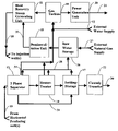
- FIG. 1 shows a plan section of the surface process flow assembly operating in simple-cycle with steam injection.
- FIG. 2 shows a plan section of the surface process flow assembly operating in combined-cycle with steam injection.
- FIG. 3 is a fanciful schematic of prior art that shows a vertical section (end view) of a steam chamber and the mobilization of hydrocarbons under gravity drainage with horizontal injection and production well bores.
- FIG. 4 is a fanciful schematic of prior art that shows a vertical section (end view) of a steam chamber and the mobilization of hydrocarbons under gravity drainage with vertical injection and a horizontal production well bores.
- FIG. 5 is a fanciful schematic that shows the American Petroleum Institute gravity of commonly referred to grades of crude oil.
- FIG. 6 is a graph schematic of prior art that show the relationship between viscosity and temperature for a typical heavy oil crude.
- FIG. 7 is a fanciful schematic of prior art that shows the derivation of permeability of a hydrocarbon-bearing reservoir.
- FIG. 8 is a graph that shows the relationship of pressure versus depth for a normally pressured reservoir.
- FIG. 9 is a fanciful schematic that shows the difference between a centralized and distributed power system.
- the thermally enhanced oil recovery system in accordance with the present invention provides a method for exploiting shallow hydrocarbon reservoir formations under primary, secondary and tertiary recovery by utilizing horizontal producing and either horizontal or vertical injection wells and surface cogeneration facility to provide the superheated high quality steam required to mobilize the in-situ hydrocarbons under gravity drainage.
- FIG. 1 shows a plan schematic of the surface equipment for the invention running in simple-cycle.
- the above ground cogeneration consists of the gas turbine 10 , the power generation unit 20 and the heat recovery steam generating (HRSG) unit 11 .
- the gas fueled turbine 10 supplies exhaust heat to the HRSG unit 11 .
- the gas turbine unit 10 is fueled by an external natural gas supply 12 and by the associated reservoir formation hydrocarbon gas that has been delivered to the surface to the production header 19 and recovered from the three-phase (liquid hydrocarbon, water and natural gas) separator 13 and the heater-treater unit. Said gas is delivered to the gas turbine 10 via the low pressure gas header line 31 .
- the demineralization unit 15 provides demineralized feed water to the heat recovery steam-generating unit 11 via water line 32 .
- the heat recovery steam-generating unit 11 generates superheated high quality steam to the steam header 18 that is fed into each horizontal injection well(s).
- Feed water is provided to the demineralization unit 15 from an external water well or other surface water source 27 that is stored in the raw water storage tank 16 and from the three-stage separator (oil, water and natural gas) 13 through water line header 28 , the heater-treater unit 14 through water line header 28 and the settling and storage tank 17 through water line header 28 .
- the gas turbine unit 10 also provides high pressure/temperature gas that drives the electrical power generator 20 and generates electricity that is sold in the local power grid 21 .
- Liquid hydrocarbons that are separated in the 3-phase separator 13 are transferred to settling and storage tank 17 via line 29 .
- the liquid hydrocarbon from settling and storage tank 17 is delivered to a custody transfer unit 22 and is sold to a local pipeline or refinery company via line 30 .
- FIG. 2 shows a plan schematic of the surface equipment for the invention running in combined-cycle.
- the above ground cogeneration consists of the gas turbine 10 , the power generation unit 20 , the heat recovery steam generating unit 11 and the steam turbine unit 33 .
- the gas fueled turbine 10 supplies exhaust heat to the heat recovery steam generating unit 11 .
- the gas turbine unit 10 is fueled by an external natural gas supply 12 and by the associated reservoir formation hydrocarbon gas that has been delivered to the surface to the production header 19 and recovered from the three-phase separator 13 and the heater-treater unit 14 . Said gas is delivered to the gas turbine 10 via the low pressure gas header line 31 .
- the demineralization unit 15 provides demineralized feed water to the heat recovery steam-generating unit 11 via water line 32 .
- the heat recovery steam-generating unit 11 generates superheated high quality steam a portion of which is delivered to the steam header 18 that is fed into each horizontal injection well(s) and another portion that is delivered to the steam turbine 33 .
- the steam turbine generates electrical power that is sold in the local power grid 21 .
- Feed water is provided to the demineralization unit 15 from an external water well or other surface water source 27 that is stored in the raw water storage tank 16 and from the three-stage separator 13 through water line header 28 , the heater-treater unit 14 through water line header 28 and the settling and storage tank 17 through water line header 28 .
- the gas turbine unit 10 also provides high pressure/temperature gas that drives the electrical power generator 20 and generates electricity that is sold in the local power grid 21 .
- Liquid hydrocarbons that are separated in the 3-phase separator 13 are transferred to settling and storage tank 17 via line 29 .
- the liquid hydrocarbon from settling and storage tank 17 is delivered to a custody transfer unit 22 and is sold to a local pipeline or refinery company via line 30 .
- FIG. 3 is a schematic of prior art that shows a vertical section (end view) through the hydrocarbon reservoir formation where horizontal injection and production well bores are used.
- Superheated high quality steam from the steam header 18 in FIG. 1 and FIG. 2 enters the horizontal injection well bore 34 at the surface and proceeds under pressure to the hydrocarbon reservoir where it then expands upward and outward to form a steam chamber 39 .
- the ceiling of the hydrocarbon reservoir 35 acts as a partial flow boundary to heat flow.
- the expanding steam chamber 39 mobilizes adjacent hydrocarbons at the ceiling of the reservoir formation 35 and causes the hydrocarbons and steam to condense along the steam chamber wall 36 .
- Gravity drainage causes the condensed mixture of hydrocarbons and water to flow downward to the base of the reservoir formation 37 where it is recovered in the horizontal producing well bore 38 that is located near the base of the heavy oil or bitumen reservoir 37 .
- the hydrocarbons and associated formation water are produced back to the surface through horizontal producing well bore 38 under artificial lift or natural flow to the surface production header 19 in FIG. 1 and FIG. 2 .
- the vertical thickness of the hydrocarbon reservoir formation from the base 37 to the top 35 must be at least 30 feet in order to initiate gravity drainage.
- FIG. 4 is a schematic of prior art that shows a vertical section (end view) through the hydrocarbon reservoir formation using a vertical injection well bore.
- Superheated high quality steam from the steam header 18 in FIG. 1 and FIG. 2 exits the vertical injector well bore 34 and rises vertically in the hydrocarbon reservoir formation to form a steam chamber 39 .
- the vertical injector well bore 34 is located above the horizontal producing well bore 38 to minimize the possibility of accidentally coning steam downward. Accidental steam breakthrough into the horizontal producing well bore 38 will reduce the hydrocarbon recovery from the formation reservoir and will lead to the increase of thermal recovery operating costs.
- Hydrocarbons and steam are condensed along the steam chamber walls 36 and flow downward due to the effect of gravity drainage until they are recovered by the horizontal producing well bore 38 .
- the horizontal producing well bore is located as close the base of the hydrocarbon reservoir formation 37 as is practical in order to maximize the recovery of hydrocarbons.
- FIG. 5 is a schematic that shows the grading of typical crude oils in accordance with the American Petroleum Institutes (API) gravity calculation.
- API American Petroleum Institutes
- FIG. 6 is a graph of prior art that shows the relationship between viscosity and temperature that was developed by Chew & Connally for a typical heavy crude with an 18-degree API gravity.
- the process's described in FIG. 1 and FIG. 2 apply to heavy crude oils with in-situ viscosities that can be reduced to less than 150 centipoise under steam assisted gravity drainage. In most cases it is uneconomic to attempt thermal recovery if the in-situ hydrocarbon viscosity cannot be reduced below 150 centipoise.
- FIGS. 1 and 2 pertains to heavy crude oil reservoirs with permeability's greater than 200 millidarcies.
- FIG. 8 is a graph that shows the relationship between pressure and depth for a normally pressured heavy oil reservoir.
- a normally pressured reservoir is assumed to be the equivalent of a head of saltwater with a gradient of 0.433 pounds per square in per vertical foot of depth.
- the process's described in FIG. 1 and FIG. 2 pertains to heavy crude oil reservoirs with bottom hole reservoir pressures that are less than 2000 pounds per square inch at a depth shallower than 4600 feet.
- FIG. 9 is a fanciful schematic that shows the difference between a centralized power system and a distributed power system.
- the large centralized power facility 44 generates power that is transmitted through the power grid 45 to the end user 46 .
- a distributed power system 48 power is generated by small power plants 47 located remotely to each other with their power being transmitted through the grid 45 to the end user 46 .
- the advantages of distributed power over centralized power generation include power grid stabilization and less vulnerability to catastrophic power line failure and loss of service to the end user 46 .
- the process's described in FIG. 1 and FIG. 2 will utilize cogeneration facilities configured in a distributed power system.
- a hydrocarbon reservoir is being considered for development under two scenarios; first, a conventional thermal recovery process using conventional boilers to generate steam and secondly by a SAGD process using hydrocarbon fired turbine-driven electrical generators and heat recovery steam generating units to produce superheated steam.
- a conventional thermal recovery process using conventional boilers to generate steam
- a SAGD process using hydrocarbon fired turbine-driven electrical generators and heat recovery steam generating units to produce superheated steam.
- the reservoir requires 220,000 pounds of steam at 600 pounds per square inch (psi) and 400 degrees Fahrenheit (F); both the boilers and the turbine generators are fueled with natural gas that costs $4.65 per thousand standard cubic.
Abstract
A combination of SAGD with cogeneration technology for exploiting shallow heavy oil and bitumen reservoirs under primary, secondary and tertiary thermal recovery. Superheated steam is generated by the heat recovery from the exhaust of an above-ground hydrocarbon powered turbine driven electric generator cogeneration plant and is injected through well bores into the hydrocarbon bearing reservoir that is traversed by at least one horizontal producing well bore and one injection well bore to heat the reservoir formation and to induce gravity drainage of the hydrocarbons and allowing their recovery from the horizontal producing well bore. Electrical power that is generated is sold to the electric grid and can be used to offset the fuel costs for the above ground hydrocarbon turbine-driven elector generators.
Description
Not Applicable
Not Applicable
Not Applicable
This invention relates generally to thermally-enhanced primary, secondary and tertiary oil recovery methods by combining steam assisted gravity drainage (SAGD) technology with hydrocarbon fueled turbine driven electrical cogeneration exhaust heat that is exchanged with feed water to supply the superheated steam to heat shallow hydrocarbon reservoir formations.
Hydrocarbon recovery can be enhanced in certain heavy oil and bitumen reservoirs by drilling closely spaced vertical production and steam injection well bores into the hydrocarbon reservoir formations and injecting steam. Under this conventional thermal secondary recovery technique, the steam can cause the heavy hydrocarbons to become mobile due to the reduction of its in-situ viscosity.
Several improvements have been made to enhance recovery of heavy oils and bitumens beyond conventional thermal techniques. One such technique is U.S. Pat. No. 4,344,485 issues Aug. 17, 1982 to Butler teaches a Steam Assisted Gravity Drainage (SAGD) method where pairs of horizontal wells, one vertically above the other are connected by a vertical fracture. A steam chamber rises above the upper well and oil warmed by conduction drains along the outside wall of the chamber to the lower production well.
The benefits of SAGD over conventional secondary thermal recovery techniques include higher oil productivity relative to the number of wells employed, higher ultimate recovery of oil in place and lower steam oil ratios.
There are problems associated with typical SAGD projects more particularly:
The economics of thermally enhanced hydrocarbon recovery projects is significantly impacted by the costs associated with generating steam. The hydrocarbon fuel to fire these boilers is usually the single most significant operating cost in a thermally enhanced recovery project and SAGD project are typically shut-in when the cost of fuel and other operating costs exceed the project's revenue; and
SAGD does not typically employ the use of super saturated steam because of the high cost of producing this steam with conventional hydrocarbon fired tube boilers. This results in using 70–80% quality steam that is less efficient in transferring heat to the heavy oil reservoir; and
The produced water associated with the hydrocarbon production from these operations is typically disposed of in commercially operated disposal wells for a fee.
U.S. Pat. No. 4,007,786 issued Feb. 15, 1977 to Schlinger, attempted to address the steam generation costs associated with conventional secondary recovery thermal projects through the use of a gas turbine and electrical generator to generate steam and to produce raw fuel by partial oxidation of the produced hydrocarbons. However, this process has several shortcomings including:
It did not address the application to SAGD technology; and
It did not address a process for primary and tertiary thermal recovery projects for heavy oil and bitumen reservoirs; and
It did not address the operation of the gas turbine generator in simple or combined cycle; and
It did not address the use of superheated steam and a heat recovery and steam-generating unit (HRSG) that is employed in generating superheated steam through cogeneration.
Other inventions have been created to overcome some of these operating issues. U.S. Pat. No. 4,694,907 utilizes cogeneration and electrical down hole steam generators to attempt thermally enhanced oil recovery in deep well reservoirs. This process is focused at overcoming heat losses associated with thermal recovery operations in deep reservoirs. This process has several shortcomings:
The combination of cogeneration and down hole heaters is very expensive and its application is for deep reservoirs; and
The process does not address the use with SAGD technology.
The object of my invention is to link two distinct concepts an electrical/steam cogeneration station to generate superheated steam with SAGD and to take advantage of the economic benefits that accrue through the use of combining these technologies for primary secondary and tertiary thermal recovery in shallow heavy oil reservoirs.
The object of this invention, therefore, is to provide a combination of an electrical/steam cogeneration station and steam assisted gravity drainage, in which super heated steam is generated at low cost from the exhaust heat from a gas fired turbine by heat exchange with feed water which is continuously delivered to the hydrocarbon reservoir formation via one or more horizontal or vertical injection well bores in order to induce SAGD in primary, secondary and tertiary thermal recovery projects.
The maximum practical pressure that steam can be raised to for thermal recovery operations is 2000 psig. This limits the applicability of this process to shallow reservoirs (less than 4000 feet vertical depth) with bottom hole reservoir pressures of less than 2000 psig due to the low hydrostatic head of the superheated steam.
It is therefore a primary aspect of one embodiment of this invention to provide an economically valuable method to recover viscous hydrocarbons from shallow hydrocarbon reservoirs using pairs of horizontal well bores or a combination of vertical and horizontal well bores and stimulating gravity drainage by the injection of superheated steam into the hydrocarbon reservoir formation by heat exchange of feed water with the exhaust gas from a gas fired turbine cogeneration facility.
It is another aspect of embodiment of the invention to provide an economically valuable method to reduce the high operating costs associated with the generation of high quality superheated steam by selling the electricity that is created by the cogeneration unit running in either simple or combined cycle into an electrical grid.
It is another aspect of an embodiment of this invention to provide an economically valuable method to recover and recycle produced reservoir formation water to supplement the feed water for the heat recovery steam-generating unit (HRSG) to generate superheated steam.
A more complete appreciation of the invention and many attendant advantages thereof will be readily obtained as the same becomes better understood by reference to the following detailed description, when considered in connection with the accompanying drawings, wherein:
The thermally enhanced oil recovery system in accordance with the present invention provides a method for exploiting shallow hydrocarbon reservoir formations under primary, secondary and tertiary recovery by utilizing horizontal producing and either horizontal or vertical injection wells and surface cogeneration facility to provide the superheated high quality steam required to mobilize the in-situ hydrocarbons under gravity drainage.
The demineralization unit 15 provides demineralized feed water to the heat recovery steam-generating unit 11 via water line 32. The heat recovery steam-generating unit 11 generates superheated high quality steam to the steam header 18 that is fed into each horizontal injection well(s).
Feed water is provided to the demineralization unit 15 from an external water well or other surface water source 27 that is stored in the raw water storage tank 16 and from the three-stage separator (oil, water and natural gas) 13 through water line header 28, the heater-treater unit 14 through water line header 28 and the settling and storage tank 17 through water line header 28.
The gas turbine unit 10 also provides high pressure/temperature gas that drives the electrical power generator 20 and generates electricity that is sold in the local power grid 21.
Liquid hydrocarbons that are separated in the 3-phase separator 13 are transferred to settling and storage tank 17 via line 29. The liquid hydrocarbon from settling and storage tank 17 is delivered to a custody transfer unit 22 and is sold to a local pipeline or refinery company via line 30.
The demineralization unit 15 provides demineralized feed water to the heat recovery steam-generating unit 11 via water line 32. The heat recovery steam-generating unit 11 generates superheated high quality steam a portion of which is delivered to the steam header 18 that is fed into each horizontal injection well(s) and another portion that is delivered to the steam turbine 33. The steam turbine generates electrical power that is sold in the local power grid 21.
Feed water is provided to the demineralization unit 15 from an external water well or other surface water source 27 that is stored in the raw water storage tank 16 and from the three-stage separator 13 through water line header 28, the heater-treater unit 14 through water line header 28 and the settling and storage tank 17 through water line header 28.
The gas turbine unit 10 also provides high pressure/temperature gas that drives the electrical power generator 20 and generates electricity that is sold in the local power grid 21.
Liquid hydrocarbons that are separated in the 3-phase separator 13 are transferred to settling and storage tank 17 via line 29. The liquid hydrocarbon from settling and storage tank 17 is delivered to a custody transfer unit 22 and is sold to a local pipeline or refinery company via line 30.
The hydrocarbons and associated formation water are produced back to the surface through horizontal producing well bore 38 under artificial lift or natural flow to the surface production header 19 in FIG. 1 and FIG. 2 .
The vertical thickness of the hydrocarbon reservoir formation from the base 37 to the top 35 must be at least 30 feet in order to initiate gravity drainage.
Hydrocarbons and steam are condensed along the steam chamber walls 36 and flow downward due to the effect of gravity drainage until they are recovered by the horizontal producing well bore 38. The horizontal producing well bore is located as close the base of the hydrocarbon reservoir formation 37 as is practical in order to maximize the recovery of hydrocarbons.
Where:
-
- k=permeability measured in millidarcies
- A=cross sectional area available for flow
- L=length available for flow
- μ=viscosity of the wetting fluid
- Q=flow rate
- ΔP=pressure drop across length L
The process's described in FIGS. 1 and 2 pertains to heavy crude oil reservoirs with permeability's greater than 200 millidarcies.
The following example demonstrates the practice and utility of the present invention but is not to be construed as limiting the scope thereof:
A hydrocarbon reservoir is being considered for development under two scenarios; first, a conventional thermal recovery process using conventional boilers to generate steam and secondly by a SAGD process using hydrocarbon fired turbine-driven electrical generators and heat recovery steam generating units to produce superheated steam. In this example it is assumed that the reservoir requires 220,000 pounds of steam at 600 pounds per square inch (psi) and 400 degrees Fahrenheit (F); both the boilers and the turbine generators are fueled with natural gas that costs $4.65 per thousand standard cubic. A comparison of these two scenarios and the economic payout for the SAGD and cogeneration scenario are presented in Table I.
| TABLE I | |
| Conventional Boiler Economics | Cogeneration Economics |
| Five-natural gas-fired tube | Two-27 megawatt natural gas |
| boilers each rated at 40,000 | fired turbine-driven |
| pounds per hour (totaling | electrical generators |
| 200,000 pounds of superheated | operated in simple cycle each |
| steam per hour) and costing | equipped with a heat recovery |
| $400,000 | steam generating unit rated |
| at 110,000 pounds of steam | |
| per hour costing $13.5 | |
| million each | |
| Assumed operating and | Assumed operating and |
| maintenance costs are | maintenance costs are |
| $36,000/month | $86,000/month |
| Assumed no Megawatts-hours of | Assumed 48 net megawatt-hours |
| power generated | generated |
| Assumed no value for | Assumed net operating income |
| electricity sold to the local | after operating, maintenance |
| grid | and fuel costs is $10,800/day |
| Calculated payout for | |
| cogeneration is 6.8 years | |
Claims (11)
1. A method for recovering hydrocarbons from a subsurface reservoir, the method comprising:
operating an above-ground, hydrocarbon-powered, turbine-driven, electric generator in simple cycle to produce electrical power and a heated exhaust;
generating a superheated high quality steam by passing water in a heat exchange relation with only the heated exhaust;
injecting the superheated steam through an injection well bore into the reservoir so as to heat the reservoir and induce steam assisted gravity drainage of the hydrocarbons; and
extracting the hydrocarbons from the reservoir through a horizontal well bore located below the injection well bore.
2. A method according to claim 1 , further comprising:
supplying a portion of the superheated steam to an electrical steam-driven generator so as to produce electrical power; and
selling the electrical power from the above-ground, hydrocarbon-powered, turbine-driven, electric generator and the electrical steam-driven generator into an electric grid.
3. The method of claim 1 , wherein the hydrocarbons have an API gravity of at least 10° but not greater than 22°.
4. The method of claim 1 , wherein the reservoir has a vertical thickness greater than 30 feet.
5. The method of claim 1 , wherein the viscosity of the hydrocarbons can be reduced to less than 150 centipoise at reservoir conditions.
6. The method of claim 1 , wherein the reservoir has an average permeability greater than 200 millidarcies.
7. The method of claim 1 , wherein the reservoir has a pressure that is less than 2000 pound per square inch.
8. The method of claim 1 , wherein the horizontal well bore is located at a base of the reservoir.
9. The method of claim 1 , further comprising supplying a portion of the hydrocarbons extracted from the formation to the above-ground, hydrocarbon-powered, turbine-driven, electric generator.
10. The method of claim 1 , further wherein a portion of the water supplied in heat exchange relation with the exhaust is water that is simultaneously produced with the hydrocarbons from the formation.
11. The method of claim 1 wherein the electric generator is a component in a distributed power system.
Priority Applications (1)
| Application Number | Priority Date | Filing Date | Title |
|---|---|---|---|
| US10/714,102 US6988549B1 (en) | 2003-11-14 | 2003-11-14 | SAGD-plus |
Applications Claiming Priority (1)
| Application Number | Priority Date | Filing Date | Title |
|---|---|---|---|
| US10/714,102 US6988549B1 (en) | 2003-11-14 | 2003-11-14 | SAGD-plus |
Publications (1)
| Publication Number | Publication Date |
|---|---|
| US6988549B1 true US6988549B1 (en) | 2006-01-24 |
Family
ID=35613956
Family Applications (1)
| Application Number | Title | Priority Date | Filing Date |
|---|---|---|---|
| US10/714,102 Expired - Fee Related US6988549B1 (en) | 2003-11-14 | 2003-11-14 | SAGD-plus |
Country Status (1)
| Country | Link |
|---|---|
| US (1) | US6988549B1 (en) |
Cited By (119)
| Publication number | Priority date | Publication date | Assignee | Title |
|---|---|---|---|---|
| US20050211434A1 (en) * | 2004-03-24 | 2005-09-29 | Gates Ian D | Process for in situ recovery of bitumen and heavy oil |
| US20080087427A1 (en) * | 2006-10-13 | 2008-04-17 | Kaminsky Robert D | Combined development of oil shale by in situ heating with a deeper hydrocarbon resource |
| US20080283241A1 (en) * | 2007-05-15 | 2008-11-20 | Kaminsky Robert D | Downhole burner wells for in situ conversion of organic-rich rock formations |
| US20080289819A1 (en) * | 2007-05-25 | 2008-11-27 | Kaminsky Robert D | Utilization of low BTU gas generated during in situ heating of organic-rich rock |
| US20080290719A1 (en) * | 2007-05-25 | 2008-11-27 | Kaminsky Robert D | Process for producing Hydrocarbon fluids combining in situ heating, a power plant and a gas plant |
| US20080289821A1 (en) * | 2007-05-23 | 2008-11-27 | Betzer Tsilevich Maoz | Integrated system and method for steam-assisted gravity drainage (sagd)-heavy oil production using low quality fuel and low quality water |
| US20090008096A1 (en) * | 2007-07-06 | 2009-01-08 | Schultz Roger L | Treating Subterranean Zones |
| US20090050319A1 (en) * | 2007-05-15 | 2009-02-26 | Kaminsky Robert D | Downhole burners for in situ conversion of organic-rich rock formations |
| US20090078414A1 (en) * | 2007-09-25 | 2009-03-26 | Schlumberger Technology Corp. | Chemically enhanced thermal recovery of heavy oil |
| WO2009058538A1 (en) * | 2007-11-02 | 2009-05-07 | Exxonmobil Upstream Research Company | High quality water recovery from thermal hydrocarbon recovery operation using vacuum technologies |
| WO2009105309A1 (en) * | 2008-02-21 | 2009-08-27 | Exxonmobil Upstream Research Company | Method and system for generating steam in the oil industry |
| US20090308608A1 (en) * | 2008-05-23 | 2009-12-17 | Kaminsky Robert D | Field Managment For Substantially Constant Composition Gas Generation |
| US20100000221A1 (en) * | 2007-04-30 | 2010-01-07 | Pfefferle William C | Method for producing fuel and power from a methane hydrate bed using a gas turbine engine |
| US20100038087A1 (en) * | 2008-08-14 | 2010-02-18 | Schlumberger Technology Corporation | Erosion mitigating apparatus and method |
| US20100089585A1 (en) * | 2006-10-13 | 2010-04-15 | Kaminsky Robert D | Method of Developing Subsurface Freeze Zone |
| US20100089575A1 (en) * | 2006-04-21 | 2010-04-15 | Kaminsky Robert D | In Situ Co-Development of Oil Shale With Mineral Recovery |
| US20100163231A1 (en) * | 2008-12-31 | 2010-07-01 | Chevron U.S.A. Inc. | Method and system for producing hydrocarbons from a hydrate reservoir using available waste heat |
| US20100193188A1 (en) * | 2007-05-23 | 2010-08-05 | Betzer Tsilevich Maoz | Integrated system and method for steam-assisted gravity drainage (sagd)-heavy oil production to produce super-heated steam without liquid waste discharge |
| US20100206565A1 (en) * | 2009-02-19 | 2010-08-19 | Conocophillips Company | Steam assisted oil recovery and carbon dioxide capture |
| US20100218946A1 (en) * | 2009-02-23 | 2010-09-02 | Symington William A | Water Treatment Following Shale Oil Production By In Situ Heating |
| US20100258308A1 (en) * | 2007-11-13 | 2010-10-14 | Speirs Brian C | Water Integration Between An In-Situ Recovery Operation And A Bitumen Mining Operation |
| US20100275600A1 (en) * | 2007-11-08 | 2010-11-04 | Speirs Brian C | System and method of recovering heat and water and generating power from bitumen mining operations |
| US20100276341A1 (en) * | 2007-11-02 | 2010-11-04 | Speirs Brian C | Heat and Water Recovery From Tailings Using Gas Humidification/Dehumidification |
| US20100276983A1 (en) * | 2007-11-09 | 2010-11-04 | James Andrew Dunn | Integration of an in-situ recovery operation with a mining operation |
| US20110000671A1 (en) * | 2008-03-28 | 2011-01-06 | Frank Hershkowitz | Low Emission Power Generation and Hydrocarbon Recovery Systems and Methods |
| US20110017455A1 (en) * | 2009-07-22 | 2011-01-27 | Conocophillips Company | Hydrocarbon recovery method |
| US20110132600A1 (en) * | 2003-06-24 | 2011-06-09 | Robert D Kaminsky | Optimized Well Spacing For In Situ Shale Oil Development |
| US20110146991A1 (en) * | 2009-12-18 | 2011-06-23 | Air Products And Chemicals, Inc. | Integrated Hydrogen Production and Hydrocarbon Extraction |
| US20110146982A1 (en) * | 2009-12-17 | 2011-06-23 | Kaminsky Robert D | Enhanced Convection For In Situ Pyrolysis of Organic-Rich Rock Formations |
| US20110232545A1 (en) * | 2008-12-10 | 2011-09-29 | Her Majesty The Queen In Right Of Canada As Represented By The Minister Of Natural Resources | High Pressure Direct Contact Oxy-Fired Steam Generator |
| US8082995B2 (en) | 2007-12-10 | 2011-12-27 | Exxonmobil Upstream Research Company | Optimization of untreated oil shale geometry to control subsidence |
| US8087460B2 (en) | 2007-03-22 | 2012-01-03 | Exxonmobil Upstream Research Company | Granular electrical connections for in situ formation heating |
| US20130068458A1 (en) * | 2011-03-04 | 2013-03-21 | Conocophillips Company | Heat recovery method for wellpad sagd steam generation |
| US20130180712A1 (en) * | 2012-01-18 | 2013-07-18 | Conocophillips Company | Method for accelerating heavy oil production |
| US8540020B2 (en) | 2009-05-05 | 2013-09-24 | Exxonmobil Upstream Research Company | Converting organic matter from a subterranean formation into producible hydrocarbons by controlling production operations based on availability of one or more production resources |
| US8616280B2 (en) | 2010-08-30 | 2013-12-31 | Exxonmobil Upstream Research Company | Wellbore mechanical integrity for in situ pyrolysis |
| US8622127B2 (en) | 2010-08-30 | 2014-01-07 | Exxonmobil Upstream Research Company | Olefin reduction for in situ pyrolysis oil generation |
| US8622133B2 (en) | 2007-03-22 | 2014-01-07 | Exxonmobil Upstream Research Company | Resistive heater for in situ formation heating |
| WO2014016062A2 (en) * | 2012-07-24 | 2014-01-30 | Siemens Aktiengesellschaft | Device and method for extracting carbon-containing substances from oil sand |
| US8770284B2 (en) | 2012-05-04 | 2014-07-08 | Exxonmobil Upstream Research Company | Systems and methods of detecting an intersection between a wellbore and a subterranean structure that includes a marker material |
| US8770289B2 (en) | 2011-12-16 | 2014-07-08 | Exxonmobil Upstream Research Company | Method and system for lifting fluids from a reservoir |
| US8984857B2 (en) | 2008-03-28 | 2015-03-24 | Exxonmobil Upstream Research Company | Low emission power generation and hydrocarbon recovery systems and methods |
| US9027321B2 (en) | 2008-03-28 | 2015-05-12 | Exxonmobil Upstream Research Company | Low emission power generation and hydrocarbon recovery systems and methods |
| US9080441B2 (en) | 2011-11-04 | 2015-07-14 | Exxonmobil Upstream Research Company | Multiple electrical connections to optimize heating for in situ pyrolysis |
| CN104948153A (en) * | 2015-04-29 | 2015-09-30 | 中国石油天然气股份有限公司 | Solvent-assisted SAGD three-dimensional physical simulation experiment method and device |
| US9222671B2 (en) | 2008-10-14 | 2015-12-29 | Exxonmobil Upstream Research Company | Methods and systems for controlling the products of combustion |
| US9265262B1 (en) | 2011-04-06 | 2016-02-23 | John L. Albanese | Hand held deer de-hide tool |
| WO2016057765A1 (en) * | 2014-10-08 | 2016-04-14 | Gtherm, Inc. | Thermally assisted oil production wells |
| US9353682B2 (en) | 2012-04-12 | 2016-05-31 | General Electric Company | Methods, systems and apparatus relating to combustion turbine power plants with exhaust gas recirculation |
| US9394772B2 (en) | 2013-11-07 | 2016-07-19 | Exxonmobil Upstream Research Company | Systems and methods for in situ resistive heating of organic matter in a subterranean formation |
| US9463417B2 (en) | 2011-03-22 | 2016-10-11 | Exxonmobil Upstream Research Company | Low emission power generation systems and methods incorporating carbon dioxide separation |
| US9482081B2 (en) | 2010-08-23 | 2016-11-01 | Schlumberger Technology Corporation | Method for preheating an oil-saturated formation |
| US9512699B2 (en) | 2013-10-22 | 2016-12-06 | Exxonmobil Upstream Research Company | Systems and methods for regulating an in situ pyrolysis process |
| US9512759B2 (en) | 2013-02-06 | 2016-12-06 | General Electric Company | System and method for catalyst heat utilization for gas turbine with exhaust gas recirculation |
| US9550190B2 (en) | 2011-11-08 | 2017-01-24 | Exxonmobil Upstream Research Company | Dewatering oil sand tailings |
| US9574496B2 (en) | 2012-12-28 | 2017-02-21 | General Electric Company | System and method for a turbine combustor |
| US9581081B2 (en) | 2013-01-13 | 2017-02-28 | General Electric Company | System and method for protecting components in a gas turbine engine with exhaust gas recirculation |
| US9587510B2 (en) | 2013-07-30 | 2017-03-07 | General Electric Company | System and method for a gas turbine engine sensor |
| US9593563B2 (en) | 2011-10-05 | 2017-03-14 | Statoil Petroleum As | Method and apparatus for generating steam for the recovery of hydrocarbon |
| US9599021B2 (en) | 2011-03-22 | 2017-03-21 | Exxonmobil Upstream Research Company | Systems and methods for controlling stoichiometric combustion in low emission turbine systems |
| US9599070B2 (en) | 2012-11-02 | 2017-03-21 | General Electric Company | System and method for oxidant compression in a stoichiometric exhaust gas recirculation gas turbine system |
| US9611756B2 (en) | 2012-11-02 | 2017-04-04 | General Electric Company | System and method for protecting components in a gas turbine engine with exhaust gas recirculation |
| US9618261B2 (en) | 2013-03-08 | 2017-04-11 | Exxonmobil Upstream Research Company | Power generation and LNG production |
| US9617914B2 (en) | 2013-06-28 | 2017-04-11 | General Electric Company | Systems and methods for monitoring gas turbine systems having exhaust gas recirculation |
| US9631542B2 (en) | 2013-06-28 | 2017-04-25 | General Electric Company | System and method for exhausting combustion gases from gas turbine engines |
| US9631815B2 (en) | 2012-12-28 | 2017-04-25 | General Electric Company | System and method for a turbine combustor |
| US9644466B2 (en) | 2014-11-21 | 2017-05-09 | Exxonmobil Upstream Research Company | Method of recovering hydrocarbons within a subsurface formation using electric current |
| US9670841B2 (en) | 2011-03-22 | 2017-06-06 | Exxonmobil Upstream Research Company | Methods of varying low emission turbine gas recycle circuits and systems and apparatus related thereto |
| US9689309B2 (en) | 2011-03-22 | 2017-06-27 | Exxonmobil Upstream Research Company | Systems and methods for carbon dioxide capture in low emission combined turbine systems |
| US9702237B2 (en) | 2013-02-20 | 2017-07-11 | Conocophillips Company | Hybrid steam generation with carbon dioxide recycle |
| US9708977B2 (en) | 2012-12-28 | 2017-07-18 | General Electric Company | System and method for reheat in gas turbine with exhaust gas recirculation |
| US9732673B2 (en) | 2010-07-02 | 2017-08-15 | Exxonmobil Upstream Research Company | Stoichiometric combustion with exhaust gas recirculation and direct contact cooler |
| US9732675B2 (en) | 2010-07-02 | 2017-08-15 | Exxonmobil Upstream Research Company | Low emission power generation systems and methods |
| US20170241247A1 (en) | 2014-10-08 | 2017-08-24 | Gtherm Energy, Inc. | Pulsing Pressure Waves Enhancing Oil and Gas Extraction in a Reservoir |
| US9752458B2 (en) | 2013-12-04 | 2017-09-05 | General Electric Company | System and method for a gas turbine engine |
| US9784185B2 (en) | 2012-04-26 | 2017-10-10 | General Electric Company | System and method for cooling a gas turbine with an exhaust gas provided by the gas turbine |
| US9783431B2 (en) | 2014-05-28 | 2017-10-10 | Katz Water Tech, Llc | Apparatus and method to remove contaminates from a fluid |
| US9784140B2 (en) | 2013-03-08 | 2017-10-10 | Exxonmobil Upstream Research Company | Processing exhaust for use in enhanced oil recovery |
| US9784182B2 (en) | 2013-03-08 | 2017-10-10 | Exxonmobil Upstream Research Company | Power generation and methane recovery from methane hydrates |
| US9803865B2 (en) | 2012-12-28 | 2017-10-31 | General Electric Company | System and method for a turbine combustor |
| US9810050B2 (en) | 2011-12-20 | 2017-11-07 | Exxonmobil Upstream Research Company | Enhanced coal-bed methane production |
| US9819292B2 (en) | 2014-12-31 | 2017-11-14 | General Electric Company | Systems and methods to respond to grid overfrequency events for a stoichiometric exhaust recirculation gas turbine |
| US9835089B2 (en) | 2013-06-28 | 2017-12-05 | General Electric Company | System and method for a fuel nozzle |
| US9863267B2 (en) | 2014-01-21 | 2018-01-09 | General Electric Company | System and method of control for a gas turbine engine |
| US9869279B2 (en) | 2012-11-02 | 2018-01-16 | General Electric Company | System and method for a multi-wall turbine combustor |
| US9869247B2 (en) | 2014-12-31 | 2018-01-16 | General Electric Company | Systems and methods of estimating a combustion equivalence ratio in a gas turbine with exhaust gas recirculation |
| US9885290B2 (en) | 2014-06-30 | 2018-02-06 | General Electric Company | Erosion suppression system and method in an exhaust gas recirculation gas turbine system |
| US9903316B2 (en) | 2010-07-02 | 2018-02-27 | Exxonmobil Upstream Research Company | Stoichiometric combustion of enriched air with exhaust gas recirculation |
| US9903588B2 (en) | 2013-07-30 | 2018-02-27 | General Electric Company | System and method for barrier in passage of combustor of gas turbine engine with exhaust gas recirculation |
| US9903271B2 (en) | 2010-07-02 | 2018-02-27 | Exxonmobil Upstream Research Company | Low emission triple-cycle power generation and CO2 separation systems and methods |
| US9915200B2 (en) | 2014-01-21 | 2018-03-13 | General Electric Company | System and method for controlling the combustion process in a gas turbine operating with exhaust gas recirculation |
| US9932874B2 (en) | 2013-02-21 | 2018-04-03 | Exxonmobil Upstream Research Company | Reducing oxygen in a gas turbine exhaust |
| US9938861B2 (en) | 2013-02-21 | 2018-04-10 | Exxonmobil Upstream Research Company | Fuel combusting method |
| US9951658B2 (en) | 2013-07-31 | 2018-04-24 | General Electric Company | System and method for an oxidant heating system |
| US10012151B2 (en) | 2013-06-28 | 2018-07-03 | General Electric Company | Systems and methods for controlling exhaust gas flow in exhaust gas recirculation gas turbine systems |
| US10030588B2 (en) | 2013-12-04 | 2018-07-24 | General Electric Company | Gas turbine combustor diagnostic system and method |
| US10047633B2 (en) | 2014-05-16 | 2018-08-14 | General Electric Company | Bearing housing |
| US10060359B2 (en) | 2014-06-30 | 2018-08-28 | General Electric Company | Method and system for combustion control for gas turbine system with exhaust gas recirculation |
| US10079564B2 (en) | 2014-01-27 | 2018-09-18 | General Electric Company | System and method for a stoichiometric exhaust gas recirculation gas turbine system |
| US10094566B2 (en) | 2015-02-04 | 2018-10-09 | General Electric Company | Systems and methods for high volumetric oxidant flow in gas turbine engine with exhaust gas recirculation |
| US10100741B2 (en) | 2012-11-02 | 2018-10-16 | General Electric Company | System and method for diffusion combustion with oxidant-diluent mixing in a stoichiometric exhaust gas recirculation gas turbine system |
| US10107495B2 (en) | 2012-11-02 | 2018-10-23 | General Electric Company | Gas turbine combustor control system for stoichiometric combustion in the presence of a diluent |
| US10145269B2 (en) | 2015-03-04 | 2018-12-04 | General Electric Company | System and method for cooling discharge flow |
| US10208677B2 (en) | 2012-12-31 | 2019-02-19 | General Electric Company | Gas turbine load control system |
| US10215412B2 (en) | 2012-11-02 | 2019-02-26 | General Electric Company | System and method for load control with diffusion combustion in a stoichiometric exhaust gas recirculation gas turbine system |
| US10221762B2 (en) | 2013-02-28 | 2019-03-05 | General Electric Company | System and method for a turbine combustor |
| US10227920B2 (en) | 2014-01-15 | 2019-03-12 | General Electric Company | Gas turbine oxidant separation system |
| US10253690B2 (en) | 2015-02-04 | 2019-04-09 | General Electric Company | Turbine system with exhaust gas recirculation, separation and extraction |
| US10267270B2 (en) | 2015-02-06 | 2019-04-23 | General Electric Company | Systems and methods for carbon black production with a gas turbine engine having exhaust gas recirculation |
| US10273880B2 (en) | 2012-04-26 | 2019-04-30 | General Electric Company | System and method of recirculating exhaust gas for use in a plurality of flow paths in a gas turbine engine |
| US10315150B2 (en) | 2013-03-08 | 2019-06-11 | Exxonmobil Upstream Research Company | Carbon dioxide recovery |
| US10316746B2 (en) | 2015-02-04 | 2019-06-11 | General Electric Company | Turbine system with exhaust gas recirculation, separation and extraction |
| US10480792B2 (en) | 2015-03-06 | 2019-11-19 | General Electric Company | Fuel staging in a gas turbine engine |
| US10655542B2 (en) | 2014-06-30 | 2020-05-19 | General Electric Company | Method and system for startup of gas turbine system drive trains with exhaust gas recirculation |
| US10711583B2 (en) | 2014-10-08 | 2020-07-14 | Gtherm Energy, Inc. | Green boiler—closed loop energy and power system to support enhanced oil recovery that is environmentally friendly |
| US10788212B2 (en) | 2015-01-12 | 2020-09-29 | General Electric Company | System and method for an oxidant passageway in a gas turbine system with exhaust gas recirculation |
| US10864482B2 (en) | 2017-08-24 | 2020-12-15 | Katz Water Tech, Llc | Apparatus system and method to separate brine from water |
| US11034605B2 (en) | 2018-03-29 | 2021-06-15 | Katz Water Tech, Llc | Apparatus system and method to extract minerals and metals from water |
| US11955782B1 (en) | 2022-11-01 | 2024-04-09 | Typhon Technology Solutions (U.S.), Llc | System and method for fracturing of underground formations using electric grid power |
Citations (14)
| Publication number | Priority date | Publication date | Assignee | Title |
|---|---|---|---|---|
| US4007786A (en) | 1975-07-28 | 1977-02-15 | Texaco Inc. | Secondary recovery of oil by steam stimulation plus the production of electrical energy and mechanical power |
| US4344485A (en) | 1979-07-10 | 1982-08-17 | Exxon Production Research Company | Method for continuously producing viscous hydrocarbons by gravity drainage while injecting heated fluids |
| US4398603A (en) * | 1981-01-07 | 1983-08-16 | Hudson's Bay Oil And Gas Company Limited | Steam generation from low quality feedwater |
| US4694907A (en) | 1986-02-21 | 1987-09-22 | Carbotek, Inc. | Thermally-enhanced oil recovery method and apparatus |
| US5503226A (en) | 1994-06-22 | 1996-04-02 | Wadleigh; Eugene E. | Process for recovering hydrocarbons by thermally assisted gravity segregation |
| US5626193A (en) | 1995-04-11 | 1997-05-06 | Elan Energy Inc. | Single horizontal wellbore gravity drainage assisted steam flooding process |
| US5826655A (en) | 1996-04-25 | 1998-10-27 | Texaco Inc | Method for enhanced recovery of viscous oil deposits |
| US6230814B1 (en) | 1999-10-14 | 2001-05-15 | Alberta Oil Sands Technology And Research Authority | Process for enhancing hydrocarbon mobility using a steam additive |
| US6240718B1 (en) | 1997-05-17 | 2001-06-05 | Abb Alstom Power Ltd. | Combination power station with power/heat cogeneration |
| US6257334B1 (en) | 1999-07-22 | 2001-07-10 | Alberta Oil Sands Technology And Research Authority | Steam-assisted gravity drainage heavy oil recovery process |
| US6357526B1 (en) | 2000-03-16 | 2002-03-19 | Kellogg Brown & Root, Inc. | Field upgrading of heavy oil and bitumen |
| US20020134083A1 (en) * | 2001-02-19 | 2002-09-26 | Staphanos Stephen T. | Generator monitoring, control and efficiency |
| US6536523B1 (en) | 1997-01-14 | 2003-03-25 | Aqua Pure Ventures Inc. | Water treatment process for thermal heavy oil recovery |
| US20030131582A1 (en) * | 2001-12-03 | 2003-07-17 | Anderson Roger E. | Coal and syngas fueled power generation systems featuring zero atmospheric emissions |
-
2003
- 2003-11-14 US US10/714,102 patent/US6988549B1/en not_active Expired - Fee Related
Patent Citations (14)
| Publication number | Priority date | Publication date | Assignee | Title |
|---|---|---|---|---|
| US4007786A (en) | 1975-07-28 | 1977-02-15 | Texaco Inc. | Secondary recovery of oil by steam stimulation plus the production of electrical energy and mechanical power |
| US4344485A (en) | 1979-07-10 | 1982-08-17 | Exxon Production Research Company | Method for continuously producing viscous hydrocarbons by gravity drainage while injecting heated fluids |
| US4398603A (en) * | 1981-01-07 | 1983-08-16 | Hudson's Bay Oil And Gas Company Limited | Steam generation from low quality feedwater |
| US4694907A (en) | 1986-02-21 | 1987-09-22 | Carbotek, Inc. | Thermally-enhanced oil recovery method and apparatus |
| US5503226A (en) | 1994-06-22 | 1996-04-02 | Wadleigh; Eugene E. | Process for recovering hydrocarbons by thermally assisted gravity segregation |
| US5626193A (en) | 1995-04-11 | 1997-05-06 | Elan Energy Inc. | Single horizontal wellbore gravity drainage assisted steam flooding process |
| US5826655A (en) | 1996-04-25 | 1998-10-27 | Texaco Inc | Method for enhanced recovery of viscous oil deposits |
| US6536523B1 (en) | 1997-01-14 | 2003-03-25 | Aqua Pure Ventures Inc. | Water treatment process for thermal heavy oil recovery |
| US6240718B1 (en) | 1997-05-17 | 2001-06-05 | Abb Alstom Power Ltd. | Combination power station with power/heat cogeneration |
| US6257334B1 (en) | 1999-07-22 | 2001-07-10 | Alberta Oil Sands Technology And Research Authority | Steam-assisted gravity drainage heavy oil recovery process |
| US6230814B1 (en) | 1999-10-14 | 2001-05-15 | Alberta Oil Sands Technology And Research Authority | Process for enhancing hydrocarbon mobility using a steam additive |
| US6357526B1 (en) | 2000-03-16 | 2002-03-19 | Kellogg Brown & Root, Inc. | Field upgrading of heavy oil and bitumen |
| US20020134083A1 (en) * | 2001-02-19 | 2002-09-26 | Staphanos Stephen T. | Generator monitoring, control and efficiency |
| US20030131582A1 (en) * | 2001-12-03 | 2003-07-17 | Anderson Roger E. | Coal and syngas fueled power generation systems featuring zero atmospheric emissions |
Cited By (169)
| Publication number | Priority date | Publication date | Assignee | Title |
|---|---|---|---|---|
| US8596355B2 (en) | 2003-06-24 | 2013-12-03 | Exxonmobil Upstream Research Company | Optimized well spacing for in situ shale oil development |
| US20110132600A1 (en) * | 2003-06-24 | 2011-06-09 | Robert D Kaminsky | Optimized Well Spacing For In Situ Shale Oil Development |
| US20050211434A1 (en) * | 2004-03-24 | 2005-09-29 | Gates Ian D | Process for in situ recovery of bitumen and heavy oil |
| US8641150B2 (en) | 2006-04-21 | 2014-02-04 | Exxonmobil Upstream Research Company | In situ co-development of oil shale with mineral recovery |
| US20100089575A1 (en) * | 2006-04-21 | 2010-04-15 | Kaminsky Robert D | In Situ Co-Development of Oil Shale With Mineral Recovery |
| US20100089585A1 (en) * | 2006-10-13 | 2010-04-15 | Kaminsky Robert D | Method of Developing Subsurface Freeze Zone |
| US8151884B2 (en) | 2006-10-13 | 2012-04-10 | Exxonmobil Upstream Research Company | Combined development of oil shale by in situ heating with a deeper hydrocarbon resource |
| US8104537B2 (en) | 2006-10-13 | 2012-01-31 | Exxonmobil Upstream Research Company | Method of developing subsurface freeze zone |
| US20080087427A1 (en) * | 2006-10-13 | 2008-04-17 | Kaminsky Robert D | Combined development of oil shale by in situ heating with a deeper hydrocarbon resource |
| US9347302B2 (en) | 2007-03-22 | 2016-05-24 | Exxonmobil Upstream Research Company | Resistive heater for in situ formation heating |
| US8087460B2 (en) | 2007-03-22 | 2012-01-03 | Exxonmobil Upstream Research Company | Granular electrical connections for in situ formation heating |
| US8622133B2 (en) | 2007-03-22 | 2014-01-07 | Exxonmobil Upstream Research Company | Resistive heater for in situ formation heating |
| US20100000221A1 (en) * | 2007-04-30 | 2010-01-07 | Pfefferle William C | Method for producing fuel and power from a methane hydrate bed using a gas turbine engine |
| US20090050319A1 (en) * | 2007-05-15 | 2009-02-26 | Kaminsky Robert D | Downhole burners for in situ conversion of organic-rich rock formations |
| US8151877B2 (en) | 2007-05-15 | 2012-04-10 | Exxonmobil Upstream Research Company | Downhole burner wells for in situ conversion of organic-rich rock formations |
| US20080283241A1 (en) * | 2007-05-15 | 2008-11-20 | Kaminsky Robert D | Downhole burner wells for in situ conversion of organic-rich rock formations |
| US8122955B2 (en) | 2007-05-15 | 2012-02-28 | Exxonmobil Upstream Research Company | Downhole burners for in situ conversion of organic-rich rock formations |
| US7699104B2 (en) | 2007-05-23 | 2010-04-20 | Maoz Betzer Tsilevich | Integrated system and method for steam-assisted gravity drainage (SAGD)-heavy oil production using low quality fuel and low quality water |
| US20080289821A1 (en) * | 2007-05-23 | 2008-11-27 | Betzer Tsilevich Maoz | Integrated system and method for steam-assisted gravity drainage (sagd)-heavy oil production using low quality fuel and low quality water |
| US20100193188A1 (en) * | 2007-05-23 | 2010-08-05 | Betzer Tsilevich Maoz | Integrated system and method for steam-assisted gravity drainage (sagd)-heavy oil production to produce super-heated steam without liquid waste discharge |
| US7931083B2 (en) | 2007-05-23 | 2011-04-26 | Ex-Tar Technologies Inc. | Integrated system and method for steam-assisted gravity drainage (SAGD)-heavy oil production to produce super-heated steam without liquid waste discharge |
| US20080289819A1 (en) * | 2007-05-25 | 2008-11-27 | Kaminsky Robert D | Utilization of low BTU gas generated during in situ heating of organic-rich rock |
| US8875789B2 (en) | 2007-05-25 | 2014-11-04 | Exxonmobil Upstream Research Company | Process for producing hydrocarbon fluids combining in situ heating, a power plant and a gas plant |
| US20080290719A1 (en) * | 2007-05-25 | 2008-11-27 | Kaminsky Robert D | Process for producing Hydrocarbon fluids combining in situ heating, a power plant and a gas plant |
| US8146664B2 (en) | 2007-05-25 | 2012-04-03 | Exxonmobil Upstream Research Company | Utilization of low BTU gas generated during in situ heating of organic-rich rock |
| WO2009009333A3 (en) * | 2007-07-06 | 2009-04-23 | Halliburton Energy Serv Inc | Treating subterranean zones |
| WO2009009333A2 (en) * | 2007-07-06 | 2009-01-15 | Halliburton Energy Services, Inc. | Treating subterranean zones |
| US20090008096A1 (en) * | 2007-07-06 | 2009-01-08 | Schultz Roger L | Treating Subterranean Zones |
| US8286707B2 (en) | 2007-07-06 | 2012-10-16 | Halliburton Energy Services, Inc. | Treating subterranean zones |
| US20090078414A1 (en) * | 2007-09-25 | 2009-03-26 | Schlumberger Technology Corp. | Chemically enhanced thermal recovery of heavy oil |
| US20090159288A1 (en) * | 2007-09-25 | 2009-06-25 | Schlumberger Technology Corporation | Chemically enhanced thermal recovery of heavy oil |
| US20100276341A1 (en) * | 2007-11-02 | 2010-11-04 | Speirs Brian C | Heat and Water Recovery From Tailings Using Gas Humidification/Dehumidification |
| US20100282593A1 (en) * | 2007-11-02 | 2010-11-11 | Speirs Brian C | Recovery of high water from produced water arising from a thermal hydrocarbon recovery operation using vaccum technologies |
| WO2009058538A1 (en) * | 2007-11-02 | 2009-05-07 | Exxonmobil Upstream Research Company | High quality water recovery from thermal hydrocarbon recovery operation using vacuum technologies |
| US20100275600A1 (en) * | 2007-11-08 | 2010-11-04 | Speirs Brian C | System and method of recovering heat and water and generating power from bitumen mining operations |
| US20100276983A1 (en) * | 2007-11-09 | 2010-11-04 | James Andrew Dunn | Integration of an in-situ recovery operation with a mining operation |
| US20100258308A1 (en) * | 2007-11-13 | 2010-10-14 | Speirs Brian C | Water Integration Between An In-Situ Recovery Operation And A Bitumen Mining Operation |
| US8082995B2 (en) | 2007-12-10 | 2011-12-27 | Exxonmobil Upstream Research Company | Optimization of untreated oil shale geometry to control subsidence |
| WO2009105309A1 (en) * | 2008-02-21 | 2009-08-27 | Exxonmobil Upstream Research Company | Method and system for generating steam in the oil industry |
| US8734545B2 (en) | 2008-03-28 | 2014-05-27 | Exxonmobil Upstream Research Company | Low emission power generation and hydrocarbon recovery systems and methods |
| US9027321B2 (en) | 2008-03-28 | 2015-05-12 | Exxonmobil Upstream Research Company | Low emission power generation and hydrocarbon recovery systems and methods |
| US20110000671A1 (en) * | 2008-03-28 | 2011-01-06 | Frank Hershkowitz | Low Emission Power Generation and Hydrocarbon Recovery Systems and Methods |
| US8984857B2 (en) | 2008-03-28 | 2015-03-24 | Exxonmobil Upstream Research Company | Low emission power generation and hydrocarbon recovery systems and methods |
| US20090308608A1 (en) * | 2008-05-23 | 2009-12-17 | Kaminsky Robert D | Field Managment For Substantially Constant Composition Gas Generation |
| US8230929B2 (en) | 2008-05-23 | 2012-07-31 | Exxonmobil Upstream Research Company | Methods of producing hydrocarbons for substantially constant composition gas generation |
| US20100038087A1 (en) * | 2008-08-14 | 2010-02-18 | Schlumberger Technology Corporation | Erosion mitigating apparatus and method |
| US9222671B2 (en) | 2008-10-14 | 2015-12-29 | Exxonmobil Upstream Research Company | Methods and systems for controlling the products of combustion |
| US9719682B2 (en) | 2008-10-14 | 2017-08-01 | Exxonmobil Upstream Research Company | Methods and systems for controlling the products of combustion |
| US10495306B2 (en) | 2008-10-14 | 2019-12-03 | Exxonmobil Upstream Research Company | Methods and systems for controlling the products of combustion |
| US9512999B2 (en) | 2008-12-10 | 2016-12-06 | Her Majesty The Queen In Right Of Canada As Represented By The Minister Of Natural Resources | High pressure direct contact oxy-fired steam generator |
| US9920923B2 (en) | 2008-12-10 | 2018-03-20 | Her Majesty The Queen In Right Of Canada As Represented By The Minister Of Natural Resources | High pressure direct contact oxy-fired steam generator |
| US20110232545A1 (en) * | 2008-12-10 | 2011-09-29 | Her Majesty The Queen In Right Of Canada As Represented By The Minister Of Natural Resources | High Pressure Direct Contact Oxy-Fired Steam Generator |
| US20100163231A1 (en) * | 2008-12-31 | 2010-07-01 | Chevron U.S.A. Inc. | Method and system for producing hydrocarbons from a hydrate reservoir using available waste heat |
| US8201626B2 (en) * | 2008-12-31 | 2012-06-19 | Chevron U.S.A. Inc. | Method and system for producing hydrocarbons from a hydrate reservoir using available waste heat |
| US8371380B2 (en) | 2009-02-19 | 2013-02-12 | Conocophillips Company | Steam assisted oil recovery and carbon dioxide capture |
| US20100206565A1 (en) * | 2009-02-19 | 2010-08-19 | Conocophillips Company | Steam assisted oil recovery and carbon dioxide capture |
| US20100218946A1 (en) * | 2009-02-23 | 2010-09-02 | Symington William A | Water Treatment Following Shale Oil Production By In Situ Heating |
| US8616279B2 (en) | 2009-02-23 | 2013-12-31 | Exxonmobil Upstream Research Company | Water treatment following shale oil production by in situ heating |
| US8540020B2 (en) | 2009-05-05 | 2013-09-24 | Exxonmobil Upstream Research Company | Converting organic matter from a subterranean formation into producible hydrocarbons by controlling production operations based on availability of one or more production resources |
| US8833454B2 (en) * | 2009-07-22 | 2014-09-16 | Conocophillips Company | Hydrocarbon recovery method |
| US20110017455A1 (en) * | 2009-07-22 | 2011-01-27 | Conocophillips Company | Hydrocarbon recovery method |
| US8863839B2 (en) | 2009-12-17 | 2014-10-21 | Exxonmobil Upstream Research Company | Enhanced convection for in situ pyrolysis of organic-rich rock formations |
| US20110146982A1 (en) * | 2009-12-17 | 2011-06-23 | Kaminsky Robert D | Enhanced Convection For In Situ Pyrolysis of Organic-Rich Rock Formations |
| US8414666B2 (en) | 2009-12-18 | 2013-04-09 | Air Products And Chemicals, Inc. | Integrated hydrogen production and hydrocarbon extraction |
| US8240370B2 (en) | 2009-12-18 | 2012-08-14 | Air Products And Chemicals, Inc. | Integrated hydrogen production and hydrocarbon extraction |
| US20110146991A1 (en) * | 2009-12-18 | 2011-06-23 | Air Products And Chemicals, Inc. | Integrated Hydrogen Production and Hydrocarbon Extraction |
| US9732673B2 (en) | 2010-07-02 | 2017-08-15 | Exxonmobil Upstream Research Company | Stoichiometric combustion with exhaust gas recirculation and direct contact cooler |
| US9732675B2 (en) | 2010-07-02 | 2017-08-15 | Exxonmobil Upstream Research Company | Low emission power generation systems and methods |
| US9903271B2 (en) | 2010-07-02 | 2018-02-27 | Exxonmobil Upstream Research Company | Low emission triple-cycle power generation and CO2 separation systems and methods |
| US9903316B2 (en) | 2010-07-02 | 2018-02-27 | Exxonmobil Upstream Research Company | Stoichiometric combustion of enriched air with exhaust gas recirculation |
| US9482081B2 (en) | 2010-08-23 | 2016-11-01 | Schlumberger Technology Corporation | Method for preheating an oil-saturated formation |
| US8616280B2 (en) | 2010-08-30 | 2013-12-31 | Exxonmobil Upstream Research Company | Wellbore mechanical integrity for in situ pyrolysis |
| US8622127B2 (en) | 2010-08-30 | 2014-01-07 | Exxonmobil Upstream Research Company | Olefin reduction for in situ pyrolysis oil generation |
| US8973658B2 (en) * | 2011-03-04 | 2015-03-10 | Conocophillips Company | Heat recovery method for wellpad SAGD steam generation |
| US20130068458A1 (en) * | 2011-03-04 | 2013-03-21 | Conocophillips Company | Heat recovery method for wellpad sagd steam generation |
| US9599021B2 (en) | 2011-03-22 | 2017-03-21 | Exxonmobil Upstream Research Company | Systems and methods for controlling stoichiometric combustion in low emission turbine systems |
| US9463417B2 (en) | 2011-03-22 | 2016-10-11 | Exxonmobil Upstream Research Company | Low emission power generation systems and methods incorporating carbon dioxide separation |
| US9689309B2 (en) | 2011-03-22 | 2017-06-27 | Exxonmobil Upstream Research Company | Systems and methods for carbon dioxide capture in low emission combined turbine systems |
| US9670841B2 (en) | 2011-03-22 | 2017-06-06 | Exxonmobil Upstream Research Company | Methods of varying low emission turbine gas recycle circuits and systems and apparatus related thereto |
| US9265262B1 (en) | 2011-04-06 | 2016-02-23 | John L. Albanese | Hand held deer de-hide tool |
| US9593563B2 (en) | 2011-10-05 | 2017-03-14 | Statoil Petroleum As | Method and apparatus for generating steam for the recovery of hydrocarbon |
| US9080441B2 (en) | 2011-11-04 | 2015-07-14 | Exxonmobil Upstream Research Company | Multiple electrical connections to optimize heating for in situ pyrolysis |
| US9550190B2 (en) | 2011-11-08 | 2017-01-24 | Exxonmobil Upstream Research Company | Dewatering oil sand tailings |
| US8770289B2 (en) | 2011-12-16 | 2014-07-08 | Exxonmobil Upstream Research Company | Method and system for lifting fluids from a reservoir |
| US9810050B2 (en) | 2011-12-20 | 2017-11-07 | Exxonmobil Upstream Research Company | Enhanced coal-bed methane production |
| US20130180712A1 (en) * | 2012-01-18 | 2013-07-18 | Conocophillips Company | Method for accelerating heavy oil production |
| US10400561B2 (en) * | 2012-01-18 | 2019-09-03 | Conocophillips Company | Method for accelerating heavy oil production |
| US9353682B2 (en) | 2012-04-12 | 2016-05-31 | General Electric Company | Methods, systems and apparatus relating to combustion turbine power plants with exhaust gas recirculation |
| US9784185B2 (en) | 2012-04-26 | 2017-10-10 | General Electric Company | System and method for cooling a gas turbine with an exhaust gas provided by the gas turbine |
| US10273880B2 (en) | 2012-04-26 | 2019-04-30 | General Electric Company | System and method of recirculating exhaust gas for use in a plurality of flow paths in a gas turbine engine |
| US8770284B2 (en) | 2012-05-04 | 2014-07-08 | Exxonmobil Upstream Research Company | Systems and methods of detecting an intersection between a wellbore and a subterranean structure that includes a marker material |
| WO2014016062A3 (en) * | 2012-07-24 | 2014-09-25 | Siemens Aktiengesellschaft | Device and method for extracting carbon-containing substances from oil sand |
| WO2014016062A2 (en) * | 2012-07-24 | 2014-01-30 | Siemens Aktiengesellschaft | Device and method for extracting carbon-containing substances from oil sand |
| RU2627791C2 (en) * | 2012-07-24 | 2017-08-11 | Сименс Акциенгезелльшафт | Device and method of producing carbon-containing substances from oil sand |
| US10047297B2 (en) * | 2012-07-24 | 2018-08-14 | Siemens Aktiengesellschaft | Device and method for extracting carbon-containing substances from oil sand |
| US10215412B2 (en) | 2012-11-02 | 2019-02-26 | General Electric Company | System and method for load control with diffusion combustion in a stoichiometric exhaust gas recirculation gas turbine system |
| US9611756B2 (en) | 2012-11-02 | 2017-04-04 | General Electric Company | System and method for protecting components in a gas turbine engine with exhaust gas recirculation |
| US10683801B2 (en) | 2012-11-02 | 2020-06-16 | General Electric Company | System and method for oxidant compression in a stoichiometric exhaust gas recirculation gas turbine system |
| US9869279B2 (en) | 2012-11-02 | 2018-01-16 | General Electric Company | System and method for a multi-wall turbine combustor |
| US10107495B2 (en) | 2012-11-02 | 2018-10-23 | General Electric Company | Gas turbine combustor control system for stoichiometric combustion in the presence of a diluent |
| US10138815B2 (en) | 2012-11-02 | 2018-11-27 | General Electric Company | System and method for diffusion combustion in a stoichiometric exhaust gas recirculation gas turbine system |
| US10161312B2 (en) | 2012-11-02 | 2018-12-25 | General Electric Company | System and method for diffusion combustion with fuel-diluent mixing in a stoichiometric exhaust gas recirculation gas turbine system |
| US10100741B2 (en) | 2012-11-02 | 2018-10-16 | General Electric Company | System and method for diffusion combustion with oxidant-diluent mixing in a stoichiometric exhaust gas recirculation gas turbine system |
| US9599070B2 (en) | 2012-11-02 | 2017-03-21 | General Electric Company | System and method for oxidant compression in a stoichiometric exhaust gas recirculation gas turbine system |
| US9803865B2 (en) | 2012-12-28 | 2017-10-31 | General Electric Company | System and method for a turbine combustor |
| US9574496B2 (en) | 2012-12-28 | 2017-02-21 | General Electric Company | System and method for a turbine combustor |
| US9708977B2 (en) | 2012-12-28 | 2017-07-18 | General Electric Company | System and method for reheat in gas turbine with exhaust gas recirculation |
| US9631815B2 (en) | 2012-12-28 | 2017-04-25 | General Electric Company | System and method for a turbine combustor |
| US10208677B2 (en) | 2012-12-31 | 2019-02-19 | General Electric Company | Gas turbine load control system |
| US9581081B2 (en) | 2013-01-13 | 2017-02-28 | General Electric Company | System and method for protecting components in a gas turbine engine with exhaust gas recirculation |
| US9512759B2 (en) | 2013-02-06 | 2016-12-06 | General Electric Company | System and method for catalyst heat utilization for gas turbine with exhaust gas recirculation |
| US9702237B2 (en) | 2013-02-20 | 2017-07-11 | Conocophillips Company | Hybrid steam generation with carbon dioxide recycle |
| US9932874B2 (en) | 2013-02-21 | 2018-04-03 | Exxonmobil Upstream Research Company | Reducing oxygen in a gas turbine exhaust |
| US10082063B2 (en) | 2013-02-21 | 2018-09-25 | Exxonmobil Upstream Research Company | Reducing oxygen in a gas turbine exhaust |
| US9938861B2 (en) | 2013-02-21 | 2018-04-10 | Exxonmobil Upstream Research Company | Fuel combusting method |
| US10221762B2 (en) | 2013-02-28 | 2019-03-05 | General Electric Company | System and method for a turbine combustor |
| US9784182B2 (en) | 2013-03-08 | 2017-10-10 | Exxonmobil Upstream Research Company | Power generation and methane recovery from methane hydrates |
| US9784140B2 (en) | 2013-03-08 | 2017-10-10 | Exxonmobil Upstream Research Company | Processing exhaust for use in enhanced oil recovery |
| US10315150B2 (en) | 2013-03-08 | 2019-06-11 | Exxonmobil Upstream Research Company | Carbon dioxide recovery |
| US9618261B2 (en) | 2013-03-08 | 2017-04-11 | Exxonmobil Upstream Research Company | Power generation and LNG production |
| US9617914B2 (en) | 2013-06-28 | 2017-04-11 | General Electric Company | Systems and methods for monitoring gas turbine systems having exhaust gas recirculation |
| US9631542B2 (en) | 2013-06-28 | 2017-04-25 | General Electric Company | System and method for exhausting combustion gases from gas turbine engines |
| US9835089B2 (en) | 2013-06-28 | 2017-12-05 | General Electric Company | System and method for a fuel nozzle |
| US10012151B2 (en) | 2013-06-28 | 2018-07-03 | General Electric Company | Systems and methods for controlling exhaust gas flow in exhaust gas recirculation gas turbine systems |
| US9587510B2 (en) | 2013-07-30 | 2017-03-07 | General Electric Company | System and method for a gas turbine engine sensor |
| US9903588B2 (en) | 2013-07-30 | 2018-02-27 | General Electric Company | System and method for barrier in passage of combustor of gas turbine engine with exhaust gas recirculation |
| US9951658B2 (en) | 2013-07-31 | 2018-04-24 | General Electric Company | System and method for an oxidant heating system |
| US9512699B2 (en) | 2013-10-22 | 2016-12-06 | Exxonmobil Upstream Research Company | Systems and methods for regulating an in situ pyrolysis process |
| US9394772B2 (en) | 2013-11-07 | 2016-07-19 | Exxonmobil Upstream Research Company | Systems and methods for in situ resistive heating of organic matter in a subterranean formation |
| US10030588B2 (en) | 2013-12-04 | 2018-07-24 | General Electric Company | Gas turbine combustor diagnostic system and method |
| US9752458B2 (en) | 2013-12-04 | 2017-09-05 | General Electric Company | System and method for a gas turbine engine |
| US10900420B2 (en) | 2013-12-04 | 2021-01-26 | Exxonmobil Upstream Research Company | Gas turbine combustor diagnostic system and method |
| US10731512B2 (en) | 2013-12-04 | 2020-08-04 | Exxonmobil Upstream Research Company | System and method for a gas turbine engine |
| US10227920B2 (en) | 2014-01-15 | 2019-03-12 | General Electric Company | Gas turbine oxidant separation system |
| US9863267B2 (en) | 2014-01-21 | 2018-01-09 | General Electric Company | System and method of control for a gas turbine engine |
| US9915200B2 (en) | 2014-01-21 | 2018-03-13 | General Electric Company | System and method for controlling the combustion process in a gas turbine operating with exhaust gas recirculation |
| US10079564B2 (en) | 2014-01-27 | 2018-09-18 | General Electric Company | System and method for a stoichiometric exhaust gas recirculation gas turbine system |
| US10727768B2 (en) | 2014-01-27 | 2020-07-28 | Exxonmobil Upstream Research Company | System and method for a stoichiometric exhaust gas recirculation gas turbine system |
| US10047633B2 (en) | 2014-05-16 | 2018-08-14 | General Electric Company | Bearing housing |
| US10882761B2 (en) | 2014-05-28 | 2021-01-05 | Katz Water Tech, Llc | Apparatus and method to remove contaminates from a fluid |
| US9783431B2 (en) | 2014-05-28 | 2017-10-10 | Katz Water Tech, Llc | Apparatus and method to remove contaminates from a fluid |
| US10858267B2 (en) | 2014-05-28 | 2020-12-08 | Katz Water Tech, Llc | Apparatus, method and system to remove contaminates from contaminated fluids |
| US10738711B2 (en) | 2014-06-30 | 2020-08-11 | Exxonmobil Upstream Research Company | Erosion suppression system and method in an exhaust gas recirculation gas turbine system |
| US10060359B2 (en) | 2014-06-30 | 2018-08-28 | General Electric Company | Method and system for combustion control for gas turbine system with exhaust gas recirculation |
| US10655542B2 (en) | 2014-06-30 | 2020-05-19 | General Electric Company | Method and system for startup of gas turbine system drive trains with exhaust gas recirculation |
| US9885290B2 (en) | 2014-06-30 | 2018-02-06 | General Electric Company | Erosion suppression system and method in an exhaust gas recirculation gas turbine system |
| US10267128B2 (en) | 2014-10-08 | 2019-04-23 | Gtherm Energy, Inc. | Pulsing pressure waves enhancing oil and gas extraction in a reservoir |
| WO2016057765A1 (en) * | 2014-10-08 | 2016-04-14 | Gtherm, Inc. | Thermally assisted oil production wells |
| US10711583B2 (en) | 2014-10-08 | 2020-07-14 | Gtherm Energy, Inc. | Green boiler—closed loop energy and power system to support enhanced oil recovery that is environmentally friendly |
| US10443364B2 (en) | 2014-10-08 | 2019-10-15 | Gtherm Energy, Inc. | Comprehensive enhanced oil recovery system |
| US20170241247A1 (en) | 2014-10-08 | 2017-08-24 | Gtherm Energy, Inc. | Pulsing Pressure Waves Enhancing Oil and Gas Extraction in a Reservoir |
| US9739122B2 (en) | 2014-11-21 | 2017-08-22 | Exxonmobil Upstream Research Company | Mitigating the effects of subsurface shunts during bulk heating of a subsurface formation |
| US9644466B2 (en) | 2014-11-21 | 2017-05-09 | Exxonmobil Upstream Research Company | Method of recovering hydrocarbons within a subsurface formation using electric current |
| US9869247B2 (en) | 2014-12-31 | 2018-01-16 | General Electric Company | Systems and methods of estimating a combustion equivalence ratio in a gas turbine with exhaust gas recirculation |
| US9819292B2 (en) | 2014-12-31 | 2017-11-14 | General Electric Company | Systems and methods to respond to grid overfrequency events for a stoichiometric exhaust recirculation gas turbine |
| US10788212B2 (en) | 2015-01-12 | 2020-09-29 | General Electric Company | System and method for an oxidant passageway in a gas turbine system with exhaust gas recirculation |
| US10316746B2 (en) | 2015-02-04 | 2019-06-11 | General Electric Company | Turbine system with exhaust gas recirculation, separation and extraction |
| US10253690B2 (en) | 2015-02-04 | 2019-04-09 | General Electric Company | Turbine system with exhaust gas recirculation, separation and extraction |
| US10094566B2 (en) | 2015-02-04 | 2018-10-09 | General Electric Company | Systems and methods for high volumetric oxidant flow in gas turbine engine with exhaust gas recirculation |
| US10267270B2 (en) | 2015-02-06 | 2019-04-23 | General Electric Company | Systems and methods for carbon black production with a gas turbine engine having exhaust gas recirculation |
| US10968781B2 (en) | 2015-03-04 | 2021-04-06 | General Electric Company | System and method for cooling discharge flow |
| US10145269B2 (en) | 2015-03-04 | 2018-12-04 | General Electric Company | System and method for cooling discharge flow |
| US10480792B2 (en) | 2015-03-06 | 2019-11-19 | General Electric Company | Fuel staging in a gas turbine engine |
| CN104948153B (en) * | 2015-04-29 | 2017-10-17 | 中国石油天然气股份有限公司 | Solvent aids in SAGD three-dimensional physical simulations experimental method and experimental provision |
| CN104948153A (en) * | 2015-04-29 | 2015-09-30 | 中国石油天然气股份有限公司 | Solvent-assisted SAGD three-dimensional physical simulation experiment method and device |
| US10864482B2 (en) | 2017-08-24 | 2020-12-15 | Katz Water Tech, Llc | Apparatus system and method to separate brine from water |
| US11034605B2 (en) | 2018-03-29 | 2021-06-15 | Katz Water Tech, Llc | Apparatus system and method to extract minerals and metals from water |
| US11718548B2 (en) | 2018-03-29 | 2023-08-08 | Katz Law Group Llc | Apparatus system and method to extract minerals and metals from water |
| US11955782B1 (en) | 2022-11-01 | 2024-04-09 | Typhon Technology Solutions (U.S.), Llc | System and method for fracturing of underground formations using electric grid power |
Similar Documents
| Publication | Publication Date | Title |
|---|---|---|
| US6988549B1 (en) | SAGD-plus | |
| US5456315A (en) | Horizontal well gravity drainage combustion process for oil recovery | |
| AU2014226412B2 (en) | Processing exhaust for use in enhanced oil recovery | |
| US9828841B2 (en) | Sagdox geometry | |
| AU2010308520B2 (en) | System and method for producing geothermal energy | |
| US8915084B2 (en) | Heat energy extraction system from underground in situ combustion of hydrocarbon reservoirs | |
| US8973658B2 (en) | Heat recovery method for wellpad SAGD steam generation | |
| US4262745A (en) | Steam stimulation process for recovering heavy oil | |
| US20120198844A1 (en) | System and Method For Producing Geothermal Energy | |
| CA2742563C (en) | Methods and systems for providing steam | |
| CA2837708C (en) | Hydrocarbon recovery through gas production control for noncondensable solvents or gases | |
| CN102947539A (en) | Conduction convection reflux retorting process | |
| CN104011331A (en) | Steam Assisted Gravity Drainage Processes With The Addition Of Oxygen Addition | |
| US20170247994A1 (en) | Thermally Assisted Oil Production Wells | |
| CN106499376A (en) | A kind of air injection auxiliary super-viscous oil underground cracking modifying process based on pit shaft heating mode | |
| US3373805A (en) | Steam lifting of heavy crudes | |
| CN105008660A (en) | Method and system of optimized steam-assisted gravity drainage with oxygen ("SAGDOX") for oil recovery | |
| US5253926A (en) | Process for making general use of the earth's heat and obtaining minerals in the zone of weakness (at depths of 13-30 km) | |
| RU2593614C1 (en) | Method for mining-well extraction scavenger oil and process equipment system therefor | |
| Jelgersma | Redevelopment of the abandoned Dutch onshore Schoonebeek oilfield with gravity assisted steam flooding | |
| Doscher et al. | The anticipated effect of diurnal injection on steamdrive efficiency | |
| WO2024050244A2 (en) | Heat harvesting of end-of-life wells | |
| RU2579061C1 (en) | Method for mine production-wells of hard (bituminous) oil and system of equipment therefor | |
| Proyer et al. | Results of a steamdrive pilot project in the Ruehlertwist field, Federal Republic of Germany | |
| Teodoriu et al. | Letting off steam and getting into hot water-harnessing the geothermal energy potential of heavy oil reservoirs |
Legal Events
| Date | Code | Title | Description |
|---|---|---|---|
| FPAY | Fee payment |
Year of fee payment: 4 |
|
| FPAY | Fee payment |
Year of fee payment: 8 |
|
| FEPP | Fee payment procedure |
Free format text: MAINTENANCE FEE REMINDER MAILED (ORIGINAL EVENT CODE: REM.) |
|
| LAPS | Lapse for failure to pay maintenance fees |
Free format text: PATENT EXPIRED FOR FAILURE TO PAY MAINTENANCE FEES (ORIGINAL EVENT CODE: EXP.) |
|
| STCH | Information on status: patent discontinuation |
Free format text: PATENT EXPIRED DUE TO NONPAYMENT OF MAINTENANCE FEES UNDER 37 CFR 1.362 |
|
| FP | Lapsed due to failure to pay maintenance fee |
Effective date: 20180124 |