US6990363B2 - Wireless communication device with an improved antenna structure - Google Patents
Wireless communication device with an improved antenna structure Download PDFInfo
- Publication number
- US6990363B2 US6990363B2 US10/007,015 US701501A US6990363B2 US 6990363 B2 US6990363 B2 US 6990363B2 US 701501 A US701501 A US 701501A US 6990363 B2 US6990363 B2 US 6990363B2
- Authority
- US
- United States
- Prior art keywords
- wireless device
- antenna
- conductive ground
- plane
- bending portion
- Prior art date
- Legal status (The legal status is an assumption and is not a legal conclusion. Google has not performed a legal analysis and makes no representation as to the accuracy of the status listed.)
- Expired - Fee Related, expires
Links
Images


Classifications
-
- H—ELECTRICITY
- H01—ELECTRIC ELEMENTS
- H01Q—ANTENNAS, i.e. RADIO AERIALS
- H01Q9/00—Electrically-short antennas having dimensions not more than twice the operating wavelength and consisting of conductive active radiating elements
- H01Q9/04—Resonant antennas
- H01Q9/0407—Substantially flat resonant element parallel to ground plane, e.g. patch antenna
- H01Q9/045—Substantially flat resonant element parallel to ground plane, e.g. patch antenna with particular feeding means
-
- H—ELECTRICITY
- H01—ELECTRIC ELEMENTS
- H01Q—ANTENNAS, i.e. RADIO AERIALS
- H01Q1/00—Details of, or arrangements associated with, antennas
- H01Q1/12—Supports; Mounting means
- H01Q1/22—Supports; Mounting means by structural association with other equipment or articles
- H01Q1/24—Supports; Mounting means by structural association with other equipment or articles with receiving set
- H01Q1/241—Supports; Mounting means by structural association with other equipment or articles with receiving set used in mobile communications, e.g. GSM
- H01Q1/242—Supports; Mounting means by structural association with other equipment or articles with receiving set used in mobile communications, e.g. GSM specially adapted for hand-held use
- H01Q1/243—Supports; Mounting means by structural association with other equipment or articles with receiving set used in mobile communications, e.g. GSM specially adapted for hand-held use with built-in antennas
Definitions
- the present invention relates to a wireless communication device with an improved antenna structure, and more particularly to a wireless communication device with an improved antenna structure suitable for a high radiation efficiency.
- FIG. 1 is a schematic perspective view of a mobile telephone with a whip antenna.
- a mobile telephone 1 has a whip antenna 3 which may be extendable and retractable.
- a helical antenna fixed to a case of the mobile telephone 1 may alternatively be provided. Further, the antenna may be integrated into the case of the mobile telephone 1 .
- the mobile wireless device has a ground which comprises an electrically conductive plate, wherein a power is supplied into between the ground and the antenna, whereby an electric image is generated. on the ground in symmetrical to an electric image on the antenna 3 .
- the antenna may comprise a dipole antenna which has a length approximately equal to one quarter of the transmitting radio wave.
- a shield in the case of the mobile wireless device, a shield covering circuitries or circuit parts, and a ground pattern of a printed board may act as the ground.
- a high frequency current flows on a surface of the conductor as the ground. Performances of the antenna may be an input impedance and a radiation efficiency. The performances of the antenna depend on the current flowing on the ground plate.
- the mobile telephone device may perform a transmission operation at a high frequency in the vicinity of 1 HGz.
- a wavelength of the radio wave is approximately 30 cm, and a quarter-wavelength of the radio wave is thus approximately 7.5 cm.
- the mobile telephone device is scaled down so that a width is, for example, about 4 cm which is narrower than the quarter-wavelength.
- Recently developed mobile telephone devices may perform transmission operations at a higher frequency near 2 GHz, wherein the wavelength of the radio wave is approximately 15 cm, and the quarter-wavelength of the radio wave is thus, slightly shorter than 4 cm.
- the width of the case of the mobile telephone is about 4 cm which is approximately equal to the quarter-wavelength of the radio wave.
- FIG. 2 is a schematic view illustrative of a model of the applied high frequency current on the ground plate of the conventional mobile telephone.
- the antenna 3 is provided at a feeding point which is positioned at a center point on a top side of the ground plate 2 .
- a first current 5 a and a second current 5 b from the feeding point on the one side including the feeding point 4 have the same phase and opposite directions, wherein fields generated. by the first and second currents 5 a and 5 b are canceled with each other, whereby effective high frequency currents, which generate the electric image, do not appear in a macroscopic view.
- the electric image to the antenna 3 is not generated. on the ground plate 2 .
- the present invention provides a wireless device including at least an antenna; and at least a conductive ground serving as a ground, through which a high frequency current flows, and the conductive ground having at least a side which is approximately one quarter wavelength of a radio wave transmitted from the antenna, the at least side of the conductive ground having a feeding point, at which the antenna is electrically connected to the conductive ground, wherein the feeding point on the side is positioned closer to one end of the side than a center position, so that the feeding point is positioned asymmetrical to the conductive ground in any directions included in a plane parallel to the conductive ground, whereby the high frequency current flowing through the conductive ground has an asymmetrical distribution of current over the conductive ground.
- FIG. 1 is a schematic perspective view of a mobile telephone with a whip antenna.
- FIG. 2 is a schematic view illustrative of a current path of the applied high frequency current on the ground plate of the conventional mobile telephone.
- FIG. 3 is a schematic view illustrative of an internal structure of a novel wire-less mobile telephone in a first embodiment in accordance with the present invention.
- FIG. 4 is a schematic view illustrative of a current path of the applied high frequency current on the ground plate of the novel wire-less mobile telephone of FIG. 3 .
- FIG. 5 is a schematic view illustrative of an internal structure of a novel wire-less mobile telephone in a second embodiment in accordance with the present invention.
- FIG. 6 is a schematic view illustrative of an internal structure of a novel wire-less mobile telephone in a third embodiment in accordance with the present invention.
- FIG. 7 is a schematic view illustrative of an internal structure of a novel wire-less mobile telephone in a fourth embodiment in accordance with the present invention.
- FIG. 8 is a schematic view illustrative of an internal structure of a novel wire-less mobile telephone in a fifth embodiment in accordance with the present invention.
- a first aspect of the present invention is a wireless device including: at least an antenna; and at least a conductive ground serving as a ground, through which a high frequency current flows, and the conductive ground having at least a side which is approximately one quarter wavelength of a radio wave transmitted from the antenna, the at least side of the conductive ground having a feeding point, at which the antenna is electrically connected to the conductive ground, wherein the feeding point is positioned asymmetrical to the conductive ground in any directions included in a plane parallel to the conductive ground.
- the feeding point on the wide is positioned closer to one end of the side than a center position.
- the high frequency current flowing through the conductive ground has an asymmetrical distribution of current over the conductive ground.
- the antenna extends in straight from the feeding point in a direction perpendicular to the side and included in the plane which includes the conductive ground.
- the antenna comprises a minority part and a majority part bounded by a bending portion from the minority part, and the minority part extends in straight from the feeding point to the bending portion in a direction perpendicular to the side and included in the plane which includes the conductive ground, and the majority part extends in straight from the bending portion in a direction parallel to the side and included in the plane which includes the conductive ground.
- the antenna comprises a minority part and a majority part bounded by a bending portion from the minority part, and the minority part extends in straight from the feeding point to the bending portion in a direction perpendicular to the side and included in the plane which includes the conductive ground, and the majority part extends from the bending portion in generally U-shape which is included in a plane both vertical to the plane which includes the conductive ground and also parallel to the side.
- the antenna comprises a minority part and a majority part bounded by a bending, portion from the minority part, and the minority part extends in straight from the feeding point to the bending portion in a direction perpendicular to the side and included in the plane which includes the conductive ground, and the majority part extends from the bending portion in open-loop shape which is included in a plane both vertical to the plane which includes the conductive ground and parallel to the side.
- the antenna comprises a minority part and a majority part bounded by a bending portion from the minority part, and the minority part extends in straight from the feeding point to the bending portion in a direction perpendicular to the side and included in the plane which includes the conductive ground, and the majority part comprises a plate extending from the bending portion in a plane both vertical to the plane which includes the conductive ground and also parallel to the side.
- the antenna is positioned in a bottom side of the wireless device.
- the antenna comprises a conductive pattern which is integrated with the conductive ground on a circuit board accommodated in a case of the wireless device.
- the antenna comprises a conductive plate provided on an inner wail of a case of the wireless device.
- the conductive ground comprises a conductive pattern on a circuit board accommodated in a case of the wireless device.
- the antenna may be accommodated in a case of the wireless device.
- the antenna may be accommodated in a bottom space defined between a bottom of the circuit board and a bottom wall of the case.
- a frequency of the radio wave may be not lower than 1 GHz.
- the wireless device may be a mobile telephone device.
- a second aspect of the present invention is a wireless device including: at least an antenna; and at least a conductive ground serving as a ground, through which a high frequency current flows, and the conductive ground having at least a side which is approximately one quarter wavelength of a radio wave transmitted from the antenna, the at least side of the conductive ground having a feeding point, at which the antenna is electrically connected to the conductive ground, wherein the feeding point on the side is positioned closer to one end of the side than a center position, so that the feeding point is positioned asymmetrical to the conductive ground in any directions included in a plane parallel to the conductive ground, whereby the high frequency current flowing through the conductive ground has an asymmetrical distribution of current over the conductive ground.
- the antenna extends in straight from the feeding point in a direction perpendicular to the side and included in the plane which includes the conductive ground.
- the antenna comprises a minority part and a majority part bounded by a bending portion from the minority part, and the minority part extends in straight from the feeding point to the bending portion in a direction perpendicular to the side and included in the plane which includes the conductive ground, and the majority part extends in straight from the bending portion in a direction parallel to the side and included in the plane which includes the conductive ground.
- the antenna comprises a minority part and a majority part bounded by a bending portion from the minority part, and the minority part extends in straight from the feeding point to the bending portion in a direction perpendicular to the side and included in the plane which includes the conductive ground, and the majority part extends from the bending portion in generally U-shape which is included in a plane both vertical to the plane which includes the conductive ground and also parallel to the side.
- the antenna comprises a minority part and a majority part bounded by a bending portion from the minority part, and the minority part extends in straight from the feeding point to the bending portion in a direction perpendicular to the side and included in the plane which includes the conductive ground, and the majority part extends from the bending portion in open-loop shape which is included in a plane both vertical to the plane which includes the conductive ground and parallel to the side.
- the antenna comprises a minority part and a majority part bounded by a bending portion from the minority part, and the minority part extends in straight from the feeding point to the bending portion in a direction perpendicular to the side and included in the plane which includes the conductive ground, and the majority part comprises a plate extending from the bending portion in a plane both vertical to the plane which includes the conductive ground and also parallel to the side.
- the antenna is positioned in a bottom side of the wireless device.
- the antenna comprises a conductive pattern which is integrated with the conductive ground on a circuit board accommodated in a case of the wireless device.
- the antenna comprises a conductive plate provided on an inner wall of a case of the wireless device.
- the conductive ground comprises a conductive pattern on a circuit board accommodated in a case of the wireless device.
- the antenna may be accommodated in a case of the wireless device.
- the antenna may be accommodated in a bottom space defined between a bottom of the circuit board and a bottom wall of the case.
- a frequency of the radio wave may be not lower than 1 GHz.
- the wireless device may be a mobile telephone device.
- FIG. 3 is a schematic view illustrative of an internal structure of a novel wire-less mobile telephone in a first embodiment in accordance with the present invention.
- FIG. 4 is a schematic view illustrative of a current path of the applied high frequency current on the ground plate of the novel wire-less mobile telephone of FIG. 3 .
- a wire-less mobile telephone has a case 1 , which accommodates a circuit board, a feeding point 4 on a bottom side of the board, and an antenna 3 extending from the feeding point 4 downwardly in straight.
- the feeding point 4 is positioned closer to one end of the bottom side than a center position of the bottom side.
- the board has a ground pattern 2 having a ground potential. An electric image symmetrical with reference to the antenna 3 is formed on the ground pattern 2 .
- a high frequency current flows on the ground pattern 2 as the surface of the board.
- First and second high frequency currents 5 a and 5 b separated at the feeding point 4 flow at the same phase and opposite directions to each other on the bottom side of the ground pattern 2 .
- a first current path for the first high frequency current 5 a on the bottom side of the ground pattern 2 is much shorter than a second current path for the second high frequency current 5 b on the bottom side of the ground pattern 2 .
- the field generated. by the first high frequency current 5 a on the first current path of the bottom side of the ground pattern 2 is canceled with a minority part of the second high frequency current 5 b on the second current path of the bottom side of the ground pattern 2 .
- the remaining majority part of the second high frequency current 5 b on the second current path of the bottom side of the ground pattern 2 is, however, not cancelled.
- a shield of the case 1 and a shield for covering the circuitries or circuit parts on the circuit board also serve as ground.
- the most outer one of the ground pattern and the shields mainly serves as the conductive ground, on which the electric image to the antenna 3 is generated.
- the antenna 3 extends from the feeding point 4 which is asymmetrical to the conductive ground in any directions, for example, both horizontal and vertical directions for avoiding cancellation of a majority of the high frequency currents on the conductive ground.
- the conductive ground has an asymmetrical distribution of the high frequency currents with reference to the antenna 3 for avoiding cancellation of a majority of the high frequency currents on the conductive ground, thereby allowing generation of an electric image on the conductive ground to the antenna 3 , resulting in an improvement in the radiation efficiency of the antenna.
- the antenna 3 projecting downwardly does not disturb telephone user in telephone conversions.
- FIG. 5 is a schematic view illustrative of an internal structure of a novel wire-less mobile telephone in a second embodiment in accordance with the present invention.
- a wire-less mobile telephone has a case 1 , which accommodates a circuit board and an antenna 6 , a feeding point 4 on a bottom side of the board.
- the antenna 3 has a bending point 6 .
- the antenna 3 is included in a plane which includes the ground pattern 2 of the circuit board.
- the antenna 3 comprises a minority part extending from the feeding point 4 downwardly up to the bending point 6 and a majority part extending from the bending point 6 horizontally, so that the majority part of the antenna 3 extends horizontally in straight and in parallel to the bottom side of the ground pattern 2 , provided that the majority of the antenna 3 is spaced from the bottom side of the ground pattern 2 at a distance defined by a short length of the minority part.
- the feeding point 4 is positioned closer to a first end of the bottom side than a center position of the bottom side.
- the majority of the antenna 3 extends horizontally in straight toward a second end opposite to the first end of the bottom side of the ground pattern 2 .
- An electric image symmetrical with reference to the antenna 3 is formed on the ground pattern 2 .
- a high frequency current flows on the ground pattern 2 as the surface of the board.
- First and second high frequency currents 5 a and 5 b separated at the feeding point 4 flow at the same phase and opposite directions to each other on the bottom side of the ground pattern 2 .
- a first current path for the first high frequency current 5 a on the bottom side of the ground pattern 2 is much shorter than a second current path for the second high frequency current 5 b on the bottom side of the ground pattern 2 .
- the field generated. by the first high frequency current 5 a on the first current path of the bottom side of the ground pattern 2 is canceled with a minority part of the second high frequency current 5 b on the second current path of the bottom side of the ground pattern 2 .
- the remaining majority part of the second high frequency current 5 b on the second current path of the bottom side of the ground pattern 2 is, however, not cancelled.
- a shield of the case 1 and a shield for covering the circuitries or circuit parts on the circuit board also serve as ground.
- the most outer one of the ground pattern and the shields mainly serves as the conductive ground, on which the electric image to the antenna 3 is generated.
- the antenna 3 extends from the feeding point 4 which is asymmetrical to the conductive, ground in any directions, for example, both horizontal and vertical directions for avoiding cancellation of a majority of the high frequency currents on the conductive ground.
- the conductive ground has an asymmetrical distribution of the high frequency currents with reference to the antenna 3 for avoiding cancellation of a majority of the high frequency currents on the, conductive ground, thereby allowing generation of an electric image on the conductive ground to the antenna 3 , resulting in an improvement in the radiation efficiency of the antenna.
- the antenna 3 does not project from the case 1 and also does extend in the plane including the ground pattern 2 , so that a further size reduction of the mobile wireless telephone device can be obtained.
- the antenna 3 may comprise a conductive pattern which is provided on the circuit board together with the ground pattern 2 .
- the conductive pattern serving as the antenna 3 and the ground pattern 2 serving as the conductive ground are integrated on the single circuit board accommodated in the case 1 .
- This modified arrangement of the antenna may allow a further reduction in size of the mobile wireless telephone device.
- the antenna is not a separate, part from the circuit board for a reduction in the number of the necessary part of the mobile wireless telephone device.
- FIG. 6 is a schematic view illustrative of an internal structure of a novel wire-less mobile telephone in a third embodiment in accordance with the present invention.
- a wire-less mobile telephone has a case 1 , which accommodates a circuit board and an antenna 6 , a feeding point 4 on a bottom side of the board.
- the antenna 3 has a bending point 6 .
- the antenna 3 comprises a minority part extending from the feeding point 4 downwardly up to the bending point 6 and a majority part extending from the bending point 6 horizontally, so that the majority part of the antenna 3 extends horizontally in generally U-shape and in parallel to the bottom side of the ground pattern 2 , provided that the majority of the antenna 3 is spaced from the bottom side of the ground pattern 2 at a distance defined by a short length of the minority part.
- the generally U-shaped majority part of the antenna 3 is included in a plane vertical to the ground pattern 2 .
- the feeding point 4 is positioned closer to a first end of the bottom side than a center position of the bottom side. An electric image symmetrical with reference to the antenna 3 is formed on the ground pattern 2 .
- a high frequency current flows on the ground pattern 2 as the surface of the board.
- First and second high frequency currents 5 a and 5 b separated at the feeding point 4 flow at the same phase and opposite directions to each other on the bottom side of the ground pattern 2 .
- a first current path for the first high frequency current 5 a on the bottom side of the ground pattern 2 is much shorter than a second current path for the second high frequency current 5 b on the bottom side of the ground pattern 2 .
- the field generated. by the first high frequency current 5 a on the first current path of the bottom side of the ground pattern 2 is canceled with a minority part of the second high frequency current 5 b on the second current path of the bottom side of the ground pattern 2 .
- the remaining majority part of the second high frequency current 5 b on the second current path of the bottom side of the ground pattern 2 is, however, not cancelled.
- a shield of the case 1 and a shield for covering the circuitries or circuit parts on the circuit board also serve as ground.
- the most outer one of the ground pattern and the shields mainly serves as the conductive ground, on which the electric image to the antenna 3 is generated.
- the antenna 3 extends from the feeding point 4 which is asymmetrical to the conductive ground in any directions, for example, both horizontal and vertical directions for avoiding cancellation of a majority of the high frequency currents on the conductive ground.
- the conductive ground has an asymmetrical distribution of the high frequency currents with reference to the antenna 3 for avoiding cancellation of a majority of the high frequency currents ion the conductive ground, thereby allowing generation of an electric image on the conductive ground to the antenna 3 , resulting in an improvement in the radiation efficiency of the antenna.
- the antenna 3 is longer than the quarter-wavelength of the radio wave and also longer than the width of the case 1 of the mobile wireless telephone device, the antenna 3 does not project from the case 1 and also does extend in the plane including the ground pattern 2 , so that a further size reduction of the mobile wireless telephone device can be obtained.
- the antenna 3 may comprise a conductive pattern which extends over a first surface of the circuit board together with the ground pattern 2 as well as extends through a through hole of the circuit board and further extends over a second surface of the circuit board.
- the conductive pattern serving as the antenna 3 and the ground pattern 2 serving as the conductive ground are integrated on the single circuit board accommodated in the case 1 .
- This modified arrangement of the antenna may allow a further reduction in size of the mobile wireless telephone device.
- the antenna is not a separate part from the circuit board for a reduction in the number of the necessary parts of the mobile wireless telephone device.
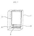
- FIG. 7 is a schematic view illustrative of an internal structure of a novel wire-less mobile telephone in a fourth embodiment in accordance with the present invention.
- a wire-less mobile telephone has a case 1 which accommodates a circuit board and an antenna 6 , a feeding point 4 on a bottom side of the board.
- the antenna 3 has a bending point 6 .
- the antenna 3 comprises a minority part extending from the feeding point 4 downwardly up to the bending point 6 and a majority part extending from the bonding point 6 horizontally, so that the majority part of the antenna 3 extends horizontally in generally open-loop shape and in parallel to the bottom side of the ground pattern 2 , provided that the majority of the antenna 3 is spaced from the bottom side of the ground pattern 2 at a distance defined by a short length of the minority part.
- the generally open-loop shaped majority part of the antenna 3 is included in a plane vertical to the ground pattern 2 .
- the feeding point 4 is positioned closer to a first end of the bottom side than a center position of the bottom side. An electric image symmetrical with reference to the antenna 3 is formed on the ground pattern 2 .
- a high frequency current flows on the ground pattern 2 as the surface of the board.
- First and second high frequency currents 5 a and 5 b separated at the feeding point 4 flow at the same phase and opposite directions to each other on the bottom side of the ground pattern 2 .
- a first current path for the first high frequency current 5 a on the bottom side of the ground pattern 2 is much shorter than a second current path for the second high frequency current 5 b on the bottom side of the ground pattern 2 .
- the field generated. by the first high frequency current 5 a on the first current path of the bottom side of the ground pattern 2 is canceled with a minority part of the second high frequency current 5 b on the second current path of the bottom side of the ground pattern 2 .
- the remaining majority part of the second high frequency current 5 b on the second current path of the bottom side of the ground pattern 2 is, however, not cancelled.
- a shield of the case 1 and a shield for covering the circuitries or circuit parts on the circuit board also serve as ground.
- the most outer one of the ground pattern and the shields mainly serves as the conductive ground, on which the electric image to the antenna 3 is generated.
- the antenna 3 extends from the feeding point 4 which is asymmetrical to the conductive ground in any directions, for example, both horizontal and vertical directions for avoiding cancellation of a majority of the high frequency currents on the conductive ground.
- the conductive ground has an asymmetrical distribution of the high frequency currents with reference to the antenna 3 for avoiding cancellation of a majority of the high frequency currents on the conductive ground, thereby allowing generation of an electric image on the conductive ground to the antenna 3 , resulting in an improvement in the radiation efficiency of the antenna.
- the antenna 3 is longer than the quarter-wavelength of the radio wave and also longer than the width of the case 1 of the mobile wireless telephone device, the antenna 3 does not project from the case 1 and also does extend in the plane including the ground pattern 2 , so that a further size reduction of the mobile wireless telephone device can be obtained.
- the antenna 3 may comprise a conductive pattern which extends over a first surface of the circuit board together with the ground pattern 2 as well as extends through a first through hole of the circuit board and further extends over a second surface of the circuit board and further extends a second through hole of the circuit board.
- the conductive pattern serving as the antenna 3 and the ground pattern 2 serving as the conductive ground are integrated on the single circuit board accommodated in the case 1 .
- This modified arrangement of the antenna may allow a further reduction in size of the mobile wireless telephone device.
- the antenna is not a separate part from the circuit board for a reduction in the number of the necessary parts of the mobile wireless telephone device.
- FIG. 8 is a schematic view illustrative of an internal structure of a novel wire-less mobile telephone in a fifth embodiment in accordance with the present invention.
- a wire-less mobile telephone has a case 1 , which accommodates a circuit board and an antenna 6 , a feeding point 4 on a bottom side of the board.
- the antenna 3 has a bending point 6 .
- the antenna 3 comprises a minority part extending from the feeding point 4 downwardly up to the bending point 6 and a majority part extending from the bending point 6 horizontally, so that the majority part of the antenna 3 comprises an expanded part which extends horizontally in generally rectangle plane and in parallel to the bottom side of the ground pattern 2 , provided that the majority of the antenna 3 is spaced from the bottom side of the ground pattern 2 at a distance defined by a short length of the minority part.
- the feeding point 4 is positioned closer to a first end of the bottom side than a center position of the bottom side. An electric image symmetrical with reference to the antenna 3 is formed on the ground pattern 2 .
- a high frequency current flows on the ground pattern 2 as the surface of the board.
- First and second high frequency currents 5 a and 5 b separated at the feeding point 4 flow at the same phase and opposite directions to each other on the bottom side of the ground pattern 2 .
- a first current path for the first high frequency current 5 a on the bottom side of the ground-pattern 2 is much shorter than a second current path for the second high frequency current 5 b on the bottom side of the ground pattern 2 .
- the field generated. by the first high frequency current 5 a on the first current path of the bottom side of the ground pattern 2 is canceled with a minority part of the second high frequency current 5 b on the second current path of the bottom side of the ground pattern 2 .
- the remaining majority part of the second high frequency current 5 b on the second current path of the bottom side of the ground pattern 2 is, however, not cancelled.
- a shield of the case 1 and a shield for covering the circuitries or circuit parts on the circuit board also serve as ground.
- the most outer one of the ground pattern and the shields mainly serves as the conductive ground, on which the electric image to the antenna 3 is generated.
- the antenna 3 extends from the feeding point 4 which is asymmetrical to the conductive ground in any directions, for example, both horizontal and vertical directions for avoiding cancellation of a majority of the high frequency currents on the conductive ground.
- the conductive ground has an asymmetrical distribution of the high frequency currents with reference to the antenna 3 for avoiding cancellation of a majority of the high frequency currents on the conductive ground, thereby allowing generation of an electric image on the conductive ground to the antenna 3 , resulting in an improvement in the radiation efficiency of the antenna.
- the antenna 3 is longer than the quarter-wavelength of the radio wave and also longer than the width of the case 1 of the mobile wireless telephone device, the antenna 3 does not project from the case 1 and also does extend in the plane vertical to the ground pattern 2 , so that a further size reduction of the mobile wireless telephone device can be obtained.
- the expanded majority part of the antenna 3 increases a wide band of the available frequency and improves a voltage standing wave ratio (VSWR).
- VSWR voltage standing wave ratio
- the antenna 3 may comprise a conductive pattern which extends over the bottom face of the case 1 .
- the antenna 3 may comprise another conductive pattern which extends over the circuit board together with the ground pattern 2 .
- the conductive pattern serving as the antenna 3 and the ground pattern 2 serving as the conductive ground are integrated on the single circuit board accommodated in the case 1 .
- This modified arrangement of the antenna may allow a further reduction in size of the mobile wireless telephone device.
- the antenna is not a separate part from the circuit board for a reduction in the number of the necessary parts of the mobile wireless telephone device.
Abstract
Description
Claims (30)
Applications Claiming Priority (2)
| Application Number | Priority Date | Filing Date | Title |
|---|---|---|---|
| JP2000-368487 | 2000-12-04 | ||
| JP2000368487A JP2002171111A (en) | 2000-12-04 | 2000-12-04 | Portable radio and antenna for it |
Publications (2)
| Publication Number | Publication Date |
|---|---|
| US20020068603A1 US20020068603A1 (en) | 2002-06-06 |
| US6990363B2 true US6990363B2 (en) | 2006-01-24 |
Family
ID=18838709
Family Applications (1)
| Application Number | Title | Priority Date | Filing Date |
|---|---|---|---|
| US10/007,015 Expired - Fee Related US6990363B2 (en) | 2000-12-04 | 2001-12-04 | Wireless communication device with an improved antenna structure |
Country Status (5)
| Country | Link |
|---|---|
| US (1) | US6990363B2 (en) |
| JP (1) | JP2002171111A (en) |
| CN (1) | CN1363997A (en) |
| GB (1) | GB2375893B (en) |
| HK (1) | HK1049074A1 (en) |
Cited By (2)
| Publication number | Priority date | Publication date | Assignee | Title |
|---|---|---|---|---|
| US20050088346A1 (en) * | 2003-10-22 | 2005-04-28 | Huan-Sheng Hwang | Multi-band antennas and radio apparatus incorporating the same |
| US20070290933A1 (en) * | 2006-06-14 | 2007-12-20 | Samsung Electro-Mechanics Co., Ltd. | Intenna-type dipole antenna for receiving broadcast signals in VHF band |
Families Citing this family (7)
| Publication number | Priority date | Publication date | Assignee | Title |
|---|---|---|---|---|
| JP2003173173A (en) * | 2001-12-07 | 2003-06-20 | Rohm Co Ltd | Liquid crystal driving device |
| FI115173B (en) * | 2002-12-31 | 2005-03-15 | Filtronic Lk Oy | Antenna for a collapsible radio |
| FR2865857B1 (en) * | 2004-02-03 | 2006-04-14 | Sagem | TELECOMMUNICATION DEVICE IN WHICH THE RADIATION DIAGRAM OF THE TELECOMMUNICATION DEVICE IS INCREASED IN AT LEAST ONE DIRECTION |
| EP1732165B1 (en) * | 2005-05-31 | 2010-11-17 | Palm, Inc. | Antenna structure for mobile communication terminals |
| US7646346B2 (en) * | 2006-11-10 | 2010-01-12 | Sony Ericsson Mobile Communications Ab | Antenna for a pen-shaped mobile phone |
| US7646347B2 (en) * | 2007-01-26 | 2010-01-12 | Sony Ericsson Mobile Communications Ab | Antenna for a pen-shaped mobile phone |
| US8884828B2 (en) | 2011-10-17 | 2014-11-11 | Sony Corporation | Mobile wireless terminal |
Citations (21)
| Publication number | Priority date | Publication date | Assignee | Title |
|---|---|---|---|---|
| US4521913A (en) * | 1981-07-11 | 1985-06-04 | Rohde & Schwarz Gmbh & Co., Kg | Multifrequency antenna matching apparatus with antomatic tuning |
| US4700194A (en) * | 1984-09-17 | 1987-10-13 | Matsushita Electric Industrial Co., Ltd. | Small antenna |
| EP0246026A2 (en) | 1986-05-09 | 1987-11-19 | Uniden Corporation | Antenna for wireless communication equipment |
| GB2255460A (en) | 1991-02-12 | 1992-11-04 | Shaye Communications Ltd | Dual antenna for cordless telephone |
| US5355524A (en) * | 1992-01-21 | 1994-10-11 | Motorola, Inc. | Integrated radio receiver/transmitter structure |
| US5367311A (en) | 1991-11-08 | 1994-11-22 | Harada Kogyo Kabushiki Kaisha | Antenna for broad-band ultrahigh frequency |
| EP0694984A1 (en) | 1994-07-25 | 1996-01-31 | Siemens Aktiengesellschaft | Antenna arrangement with an asymmetric ground distribution particularly for wireless telecommunications systems |
| US5757326A (en) * | 1993-03-29 | 1998-05-26 | Seiko Epson Corporation | Slot antenna device and wireless apparatus employing the antenna device |
| WO1999022420A1 (en) | 1997-10-28 | 1999-05-06 | Telefonaktiebolaget Lm Ericsson (Publ) | Multiple band, multiple branch antenna for mobile phone |
| EP0924795A1 (en) | 1997-12-19 | 1999-06-23 | Murata Manufacturing Co., Ltd. | Surface mount antenna and communication apparatus including the same |
| US6002367A (en) * | 1996-05-17 | 1999-12-14 | Allgon Ab | Planar antenna device |
| US6049314A (en) * | 1998-11-17 | 2000-04-11 | Xertex Technologies, Inc. | Wide band antenna having unitary radiator/ground plane |
| GB2345209A (en) | 1998-12-22 | 2000-06-28 | Hi Key Ltd | A vehicle access radio receiver with a printed antenna and an earthed shield |
| US6097339A (en) * | 1998-02-23 | 2000-08-01 | Qualcomm Incorporated | Substrate antenna |
| US6140966A (en) * | 1997-07-08 | 2000-10-31 | Nokia Mobile Phones Limited | Double resonance antenna structure for several frequency ranges |
| US6147652A (en) | 1997-09-19 | 2000-11-14 | Kabushiki Kaisha Toshiba | Antenna apparatus |
| WO2001026181A1 (en) | 1999-10-06 | 2001-04-12 | Rangestar Wireless, Inc. | Single and multiband quarter wave resonator |
| US6326927B1 (en) * | 1999-07-21 | 2001-12-04 | Range Star Wireless, Inc. | Capacitively-tuned broadband antenna structure |
| US6342855B1 (en) * | 1996-09-23 | 2002-01-29 | Lutz Rothe | Mobile radiotelephony planar antenna |
| WO2002029988A1 (en) | 2000-10-04 | 2002-04-11 | Motorola Inc. | Folded inverted f antenna for gps applications |
| US6771223B1 (en) * | 2000-10-31 | 2004-08-03 | Mitsubishi Denki Kabushiki Kaisha | Antenna device and portable machine |
Family Cites Families (3)
| Publication number | Priority date | Publication date | Assignee | Title |
|---|---|---|---|---|
| JP3251680B2 (en) * | 1991-12-26 | 2002-01-28 | 株式会社東芝 | Portable radio |
| JP3467752B2 (en) * | 1998-03-18 | 2003-11-17 | Necトーキン株式会社 | Mobile communication terminal and its antenna device |
| JP2000261532A (en) * | 1999-03-05 | 2000-09-22 | Matsushita Electric Ind Co Ltd | Mobile portable terminal |
-
2000
- 2000-12-04 JP JP2000368487A patent/JP2002171111A/en active Pending
-
2001
- 2001-12-04 CN CN01142891A patent/CN1363997A/en active Pending
- 2001-12-04 GB GB0129006A patent/GB2375893B/en not_active Expired - Fee Related
- 2001-12-04 US US10/007,015 patent/US6990363B2/en not_active Expired - Fee Related
-
2003
- 2003-01-29 HK HK03100739.3A patent/HK1049074A1/en unknown
Patent Citations (22)
| Publication number | Priority date | Publication date | Assignee | Title |
|---|---|---|---|---|
| US4521913A (en) * | 1981-07-11 | 1985-06-04 | Rohde & Schwarz Gmbh & Co., Kg | Multifrequency antenna matching apparatus with antomatic tuning |
| US4700194A (en) * | 1984-09-17 | 1987-10-13 | Matsushita Electric Industrial Co., Ltd. | Small antenna |
| EP0246026A2 (en) | 1986-05-09 | 1987-11-19 | Uniden Corporation | Antenna for wireless communication equipment |
| GB2255460A (en) | 1991-02-12 | 1992-11-04 | Shaye Communications Ltd | Dual antenna for cordless telephone |
| US5367311A (en) | 1991-11-08 | 1994-11-22 | Harada Kogyo Kabushiki Kaisha | Antenna for broad-band ultrahigh frequency |
| US5355524A (en) * | 1992-01-21 | 1994-10-11 | Motorola, Inc. | Integrated radio receiver/transmitter structure |
| US5757326A (en) * | 1993-03-29 | 1998-05-26 | Seiko Epson Corporation | Slot antenna device and wireless apparatus employing the antenna device |
| EP0694984A1 (en) | 1994-07-25 | 1996-01-31 | Siemens Aktiengesellschaft | Antenna arrangement with an asymmetric ground distribution particularly for wireless telecommunications systems |
| US6002367A (en) * | 1996-05-17 | 1999-12-14 | Allgon Ab | Planar antenna device |
| US6342855B1 (en) * | 1996-09-23 | 2002-01-29 | Lutz Rothe | Mobile radiotelephony planar antenna |
| US6140966A (en) * | 1997-07-08 | 2000-10-31 | Nokia Mobile Phones Limited | Double resonance antenna structure for several frequency ranges |
| US6147652A (en) | 1997-09-19 | 2000-11-14 | Kabushiki Kaisha Toshiba | Antenna apparatus |
| WO1999022420A1 (en) | 1997-10-28 | 1999-05-06 | Telefonaktiebolaget Lm Ericsson (Publ) | Multiple band, multiple branch antenna for mobile phone |
| EP0924795A1 (en) | 1997-12-19 | 1999-06-23 | Murata Manufacturing Co., Ltd. | Surface mount antenna and communication apparatus including the same |
| US6097339A (en) * | 1998-02-23 | 2000-08-01 | Qualcomm Incorporated | Substrate antenna |
| US6049314A (en) * | 1998-11-17 | 2000-04-11 | Xertex Technologies, Inc. | Wide band antenna having unitary radiator/ground plane |
| US6133883A (en) * | 1998-11-17 | 2000-10-17 | Xertex Technologies, Inc. | Wide band antenna having unitary radiator/ground plane |
| GB2345209A (en) | 1998-12-22 | 2000-06-28 | Hi Key Ltd | A vehicle access radio receiver with a printed antenna and an earthed shield |
| US6326927B1 (en) * | 1999-07-21 | 2001-12-04 | Range Star Wireless, Inc. | Capacitively-tuned broadband antenna structure |
| WO2001026181A1 (en) | 1999-10-06 | 2001-04-12 | Rangestar Wireless, Inc. | Single and multiband quarter wave resonator |
| WO2002029988A1 (en) | 2000-10-04 | 2002-04-11 | Motorola Inc. | Folded inverted f antenna for gps applications |
| US6771223B1 (en) * | 2000-10-31 | 2004-08-03 | Mitsubishi Denki Kabushiki Kaisha | Antenna device and portable machine |
Non-Patent Citations (4)
| Title |
|---|
| Abstract of PCT International Publication No. WO 99/22420, dated May 6, 1999. |
| Chinese Office Action dated Apr. 2, 2004 with English language translation. |
| Chinese Office Action dated Dec. 5, 2003. |
| Iwai Toru (JP-63-222504) Antenna. dated of publication of application Sep. 16, 1998. * |
Cited By (4)
| Publication number | Priority date | Publication date | Assignee | Title |
|---|---|---|---|---|
| US20050088346A1 (en) * | 2003-10-22 | 2005-04-28 | Huan-Sheng Hwang | Multi-band antennas and radio apparatus incorporating the same |
| US7592958B2 (en) * | 2003-10-22 | 2009-09-22 | Sony Ericsson Mobile Communications, Ab | Multi-band antennas and radio apparatus incorporating the same |
| US20070290933A1 (en) * | 2006-06-14 | 2007-12-20 | Samsung Electro-Mechanics Co., Ltd. | Intenna-type dipole antenna for receiving broadcast signals in VHF band |
| US7471250B2 (en) * | 2006-06-14 | 2008-12-30 | Samsung Electronics Co., Ltd. | Intenna-type dipole antenna for receiving broadcast signals in VHF band |
Also Published As
| Publication number | Publication date |
|---|---|
| GB2375893A (en) | 2002-11-27 |
| CN1363997A (en) | 2002-08-14 |
| HK1049074A1 (en) | 2003-04-25 |
| US20020068603A1 (en) | 2002-06-06 |
| JP2002171111A (en) | 2002-06-14 |
| GB0129006D0 (en) | 2002-01-23 |
| GB2375893B (en) | 2005-02-02 |
Similar Documents
| Publication | Publication Date | Title |
|---|---|---|
| US6856294B2 (en) | Compact, low profile, single feed, multi-band, printed antenna | |
| US7429955B2 (en) | Multi-band antenna | |
| US7170456B2 (en) | Dielectric chip antenna structure | |
| CN210956994U (en) | Antenna assembly and electronic equipment | |
| US20050030239A1 (en) | Antenna of small dimensions | |
| JP4171008B2 (en) | Antenna device and portable radio | |
| US7969371B2 (en) | Small monopole antenna having loop element included feeder | |
| JP2001339226A (en) | Antenna system | |
| KR20010075231A (en) | Capacitively-tune broadband antenna structure | |
| US20030234742A1 (en) | Dual-frequency inverted-F antenna | |
| EP1032076B1 (en) | Antenna apparatus and radio device using antenna apparatus | |
| JP2007221344A (en) | Antenna system, ic loaded with same and portable terminal loaded with antenna system | |
| US6222496B1 (en) | Modified inverted-F antenna | |
| JP2007329962A (en) | Communication terminal | |
| TWI381587B (en) | Multi-band antenna | |
| US6990363B2 (en) | Wireless communication device with an improved antenna structure | |
| JP2004072731A (en) | Monopole antenna device, communication system, and mobile communication system | |
| JP7074637B2 (en) | Broadband antenna system | |
| US6563467B1 (en) | Efficient antenna pattern shaping structure and associated radio circuitry and antenna | |
| EP1445825B1 (en) | A portable wireless apparatus | |
| CN109309284A (en) | Antenna assembly and mobile device | |
| JP2006527509A (en) | Mobile communication terminal built-in antenna with central feeding structure | |
| CN212342814U (en) | Printed antenna and electronic device | |
| KR20020091789A (en) | Built-in Patch Antenna for Mobile Communication Terminal and Method for Manufacturing it | |
| US20230246341A1 (en) | Slot antenna device and slot antenna combination system |
Legal Events
| Date | Code | Title | Description |
|---|---|---|---|
| AS | Assignment |
Owner name: NEC CORPORATION, JAPAN Free format text: ASSIGNMENT OF ASSIGNORS INTEREST;ASSIGNORS:ITO, RYO;ONO, TAKAO;REEL/FRAME:012369/0555 Effective date: 20011130 |
|
| FEPP | Fee payment procedure |
Free format text: PAYER NUMBER DE-ASSIGNED (ORIGINAL EVENT CODE: RMPN); ENTITY STATUS OF PATENT OWNER: LARGE ENTITY Free format text: PAYOR NUMBER ASSIGNED (ORIGINAL EVENT CODE: ASPN); ENTITY STATUS OF PATENT OWNER: LARGE ENTITY |
|
| FPAY | Fee payment |
Year of fee payment: 4 |
|
| FPAY | Fee payment |
Year of fee payment: 8 |
|
| AS | Assignment |
Owner name: LENOVO INNOVATIONS LIMITED (HONG KONG), HONG KONG Free format text: ASSIGNMENT OF ASSIGNORS INTEREST;ASSIGNOR:NEC CORPORATION;REEL/FRAME:033720/0767 Effective date: 20140618 |
|
| FEPP | Fee payment procedure |
Free format text: MAINTENANCE FEE REMINDER MAILED (ORIGINAL EVENT CODE: REM.) |
|
| LAPS | Lapse for failure to pay maintenance fees |
Free format text: PATENT EXPIRED FOR FAILURE TO PAY MAINTENANCE FEES (ORIGINAL EVENT CODE: EXP.) |
|
| STCH | Information on status: patent discontinuation |
Free format text: PATENT EXPIRED DUE TO NONPAYMENT OF MAINTENANCE FEES UNDER 37 CFR 1.362 |
|
| FP | Lapsed due to failure to pay maintenance fee |
Effective date: 20180124 |