US6996067B1 - Apparatus for and method of providing and measuring data throughput to and from a packet data network - Google Patents
Apparatus for and method of providing and measuring data throughput to and from a packet data network Download PDFInfo
- Publication number
- US6996067B1 US6996067B1 US09/455,517 US45551799A US6996067B1 US 6996067 B1 US6996067 B1 US 6996067B1 US 45551799 A US45551799 A US 45551799A US 6996067 B1 US6996067 B1 US 6996067B1
- Authority
- US
- United States
- Prior art keywords
- data
- remote
- downstream
- upstream
- facility
- Prior art date
- Legal status (The legal status is an assumption and is not a legal conclusion. Google has not performed a legal analysis and makes no representation as to the accuracy of the status listed.)
- Expired - Fee Related
Links
Images


Classifications
-
- H—ELECTRICITY
- H04—ELECTRIC COMMUNICATION TECHNIQUE
- H04L—TRANSMISSION OF DIGITAL INFORMATION, e.g. TELEGRAPHIC COMMUNICATION
- H04L43/00—Arrangements for monitoring or testing data switching networks
- H04L43/50—Testing arrangements
-
- H—ELECTRICITY
- H04—ELECTRIC COMMUNICATION TECHNIQUE
- H04L—TRANSMISSION OF DIGITAL INFORMATION, e.g. TELEGRAPHIC COMMUNICATION
- H04L43/00—Arrangements for monitoring or testing data switching networks
- H04L43/08—Monitoring or testing based on specific metrics, e.g. QoS, energy consumption or environmental parameters
- H04L43/0876—Network utilisation, e.g. volume of load or congestion level
- H04L43/0888—Throughput
-
- H—ELECTRICITY
- H04—ELECTRIC COMMUNICATION TECHNIQUE
- H04L—TRANSMISSION OF DIGITAL INFORMATION, e.g. TELEGRAPHIC COMMUNICATION
- H04L43/00—Arrangements for monitoring or testing data switching networks
- H04L43/06—Generation of reports
-
- H—ELECTRICITY
- H04—ELECTRIC COMMUNICATION TECHNIQUE
- H04L—TRANSMISSION OF DIGITAL INFORMATION, e.g. TELEGRAPHIC COMMUNICATION
- H04L43/00—Arrangements for monitoring or testing data switching networks
- H04L43/08—Monitoring or testing based on specific metrics, e.g. QoS, energy consumption or environmental parameters
- H04L43/0876—Network utilisation, e.g. volume of load or congestion level
- H04L43/0894—Packet rate
Definitions
- the invention relates to a packet data network and, in particular a system for and method of providing high speed local loop access throughput testing.
- the embedded telephone plant already includes extensive facilities supporting communication from central relay and switching facilities to most homes and offices. While, until recently, this plant was only considered in terms of providing voice grade and low speed data communications, efforts have been made to enhance and extend the life of the network to further support the increased demands of high speed data transport. At the central office level, this can be accomplished by installation of new data switching and routing equipment.
- the existing distribution system is not as easily upgraded.
- the telephone network includes extensive webs of buried and aerial copper cables, largely in the form of “twisted pair”, i.e., ordinary pairs of copper twisted around each other to reduce crosstalk or electromagnetic induction between pairs of wires.
- the service area of a particular wire center and/or central office may be increased and/or the amount of new cabling to be installed may be minimized by the use of a subscriber loop carrier (SLC) system to “virtually” extend central office switching and transmission facilities into the field. While these transmission facilities are designed to support voice grade telephone circuits in the 300 Hz to 2700 KHz range, using advanced digital encoding techniques and equipment has enabled the transmission of digital data over these same lines.
- SLC subscriber loop carrier
- DSL digital subscriber line
- the DSL signal is recovered from the loop and interfaced to a high speed data network for transmission to a service provider (SP).
- SP service provider
- the voice telephone signal is separately routed to a voice switch such as a Lucent 5ESS or Nortel DMS-100.
- the data signal is either handed off to the SP or corporate LAN.
- the SP's data network is then used to complete routing of the traffic to a distant server or other form of terminal by providing bidirectional communications interface with other systems and/or networks.
- the SP is an ISP providing access to, for example, the world wide web (www)
- the signal has the potential of being routed through and by way of many further backbone and regional networks before reaching the desired server or client node.
- Optical fiber connects information sources to the switching component of the network utilizing a standardized transport stream such as SONET OC—N.
- a broadband asynchronous transfer mode (ATM) switch, a digital cross-connect switch or other distribution mechanisms may be utilized to interconnect information sources and subscribers.
- a level 1 gateway is utilized to control access to all information resources on the network.
- the interface units frequency multiplex digital information with voice information to the subscriber and support transmission of a reverse control channel from the subscriber to the central office for transmission back to the information provider.
- Other modes are supported which permit selective bi-directional and reversible communications as well.
- a data transmission system includes a remote computer having a modem and a display.
- the display provides a visual indication of a downstream data rate received, and an upstream data rate transmitted by and through the modem.
- a transmission facility connects the modem to a central communications facility having a corresponding modem so as to provide data communications between the central facility and the remote computer system.
- the central facility includes a packet switch connected to the modem so as to provide bidirectional digital communications with the remote computer via its modem.
- a test server is also connected to the packet switch and configured to transmit and receive respective predetermined downstream and upstream messages to and from the remote computer. As a result, the actual numeric value of the calculated throughput rate is displayed to the user. At the same time, the results of the throughput test are transmitted to and stored on the throughput server.
- the data transmission system also includes a bi-directional interface with a remote data network connected to the packet switch.
- the data transmission system selectively provides communications between the remote computer and either the test server or the remote data network.
- the remote data network alternatively provides connectivity to the remote compute via the central facility in support of, for example, Internet connectivity and other forms of remote access.
- the remote computer is programmed to calculate downstream and upstream data rates independently of each other.
- the test server is configured to download executable code (e.g., JAVA applets) to the remote computer, thereby providing the necessary software in support of the visual indication of the downstream and upstream data rates.
- the remote computer accordingly, may include a browser to provide a user interface with the remote network wherein the executable code comprises an applet executed by the browser.
- the modems may be DSL transceivers, the modem at the computer comprising an ADSL terminal unit-remote (ATU-R).
- ATU-R ADSL terminal unit-remote
- the transmission facility may include twisted-pair, subscriber line interface circuits (SLIC) or a digital loop carrier line interface circuit (DLC-SLIC).
- the central facility may include a telephone network central office, wire center, and/or a remote telecommunication equipment center, the latter extending the capabilities and facilities of a central office into the field.
- a data transmission network includes a plurality of remote computers, each having a modem and a display capable of providing a visual indication of downstream and upstream data rates received and transmitted by the data modem.
- a transmission facility connects the modems to a central office facility having a plurality of local modems communicating with corresponding ones of the remote computer modems.
- a packet switch at the central office facility is connected to the local modems to provide bi-directional digital data communication through the packet switch and the transmission facilities between the computers and at least one remote data network.
- a test server is connected to the packet switch so as to transmit and receive downstream and upstream test messages to a selected computer. In response to these test messages, the remote computers are configured to provide a visual indication of the respective upstream and downstream data rates.
- a method of measuring a performance of a data transmission facility includes the steps of connecting a remote data terminal device to a central communications facility via the data transmission facility and rerouting, at the central communications facility, a data communication connectivity of the remote data terminal device with a remote data network so as to instead establish connectivity between the remote data terminal device and a test server.
- a test program is downloaded from the test server to the remote data terminal and an upstream test signal is transmitted from the remote data terminal to the test server.
- a downstream test signal is transmitted from the test server to the data terminal so that the remote data terminal displays a performance of the data transmission facility in transmitting the upstream and downstream test signals.
- FIG. 1 is a block diagram of a throughput test server (TTS) configuration over a high speed data network.
- TTS throughput test server
- FIG. 2 is a block diagram of physical connectivity of a TTS.
- FIG. 3 is a block diagram of major subsystems of an ADSL data network (ADN) including a TTS.
- ADN ADSL data network
- FIG. 4 is a flow diagram of a method of testing an ADN using a TTS capability.
- FIGS. 5 a – 5 e are computer browser screen presentations provided to a customer accessing the TTS.
- FIG. 6 is a block diagram of an ADN physical architecture with centralized gateway router.
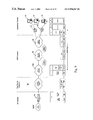
- FIG. 7 is a block diagram of a point-to-point (PPP) termination over ATM user plane protocol architecture.
- PPP point-to-point
- FIG. 8 is a block diagram of a PPP tunneling user plane protocol architecture.
- FIG. 9 is a block diagram of a PPP termination user plane protocol architecture.
- FIG. 10 is a block diagram of a protocol architecture used to interconnect a subscriber's PC to an ATU-R via an ATM25 NIC card.
- the throughput test server includes software and related hardware for the measurement of upstream (from a remote customer PC) and downstream (to the remote customer PC) throughput rates on digital subscriber lines (DSLs) including ADSL and similar lines.
- TTS systems and results may be employed and used by local exchange carriers (LECs) to facilitate identification and resolution of problems in the ADSL and other types of DSLs.
- LECs local exchange carriers
- the LEC only provides connectivity from the customer premises to a local or regional interface such as a point-of-presence (POP) maintained by a service provider (SP) (such as an Internet service provider (ISP)), it is often difficult to determine which portion of a communications connection may be malfunctioning.
- POP point-of-presence
- SP service provider
- ISP Internet service provider
- the TTS speeds fault isolation and confirms operation of the network segment provided by the LEC without requiring dispatch of a service technician.
- the TTS is used when data services subscriber reports an apparent speed problem with an ADSL line to the LEC, and the problem cannot be easily identified or solved.
- a technician connects the customer to the TTS server, which temporarily substitutes for the customer's regular SP.
- the customer using a web browser, downloads from the TTS (which acts as a web server) a throughput test web page and executable applet to the PC.
- the applet By running the applet, the customer performs measurements of upstream and downstream throughput rates of the ADSL connection.
- the applet presents results to the customer, and automatically sends results to the LEC for further analysis (test results are written to a log file on the TTS. After the test, the applet is automatically deleted from the customer PC when the Web Browser is closed.
- the TTS may be deployed with multiple sets of input parameters, each optimized for testing of a particular speed of ADSL service.
- the throughput test server can support measurements of any rates upstream or downstream.
- the throughput test server is adapted for use with presently deployed ADSL systems operating at, for example, 640 K BPS, 1.6 MBPS, or 7.1 MBPS, although it is adaptable to other operating speeds as they become available and are deployed.
- Each input parameter set is embedded in the web page that initiates the applet.
- the TTS includes a user interface providing for simplified use and installation without installation or provision of specialized hardware at the customer site. Instead, the system only requires that the customer has installed on the PC a recent version of a Java-enabled web browser, and that the PC has sufficient resources (disk space, RAM) to run the applet. In a few cases, the customer may be required to change some internal settings of the browser. These changes will not usually affect the customer's PC and, if desired, can be reversed after completion of testing. The tests may be repeated multiple times as necessary or desired. Test results are stored on the TTS server for reference and analysis by LEC personnel including service representatives and technicians.
- the TTS platform and supporting software include four primary components:
- the TTS is a JAVA program residing on the put downstream packet throughput server that controls sending Server streams, and echo and receiving of datagrams. This is the reflections of main software component for upstream packet throughput tests on the service provider streams side of ADSL communications.
- Client Provides the GUI
- the client applet is stored in the Applet interface to the document directory of the web server throughput software installed on TTS. It is downloaded to and allows the client the client's PC when the client accesses to run the through- the TTS. Using the applet, the client put test from the initiates throughput tests.
- the applet is customer premises. interpreted by the customer's Java- The applet generates enabled web browser.
- Applet input upstream packet parameters are embedded in the streams and initiates initiating web page. (triggers) downstream packet streams.
- Web Manages HTML test Web server is standard, commercially Server web page with an available software that presents the applet throughput test web page (and associated applet) to an external network. The web server is set to allow access by customers identified by the LEC.
- JAVA Provides the JAVA JAVA engine must be capable of Runtime interpreter on TTS. running in “native” mode. Environ- ment
- FIG. 1 presents a block architecture and corresponding protocol stack used with the TTS in a high speed data network.
- the TTS provides throughput testing for a large public network of subscribers at multiple customer locations 10 a , 10 b , 10 c , etc.
- Each of these locations may include various data communications terminals, typically in the form of personal and laptop computers 12 a and 12 b .
- These resources may function as clients in a server-client relationship to be described.
- the clients may be networked over a local area network and provided with communications connectivity via ADSL terminal unit-remote (ATU-R) 14 .
- ATU-R ADSL terminal unit-remote
- Also shown at customer location 10 a is a telephone system 16 .
- a POTS splitter 18 is connected to copper loop 20 , typically consisting of a twisted pair, for providing data signal connectivity to ATU-R 14 and POTS signaling to telephone system 16 .
- Access subsystem 30 including a digital subscriber line access multiplexer (DSLAM), is provided at a central office (CO) or at a remote terminal (RT) location for providing data signaling connectivity with ATU-R 14 .
- a CO splitter (not shown) may be provided at the point where transmission facility 20 interfaces with DSLAM 30 to split off the POTS signal and provide the same to a conventional central office voice switch.
- DSLAM 30 is interfaced with ATM switching subsystem 40 providing multiplexed data signals which are then supplied to gateway routers 50 .
- gateway routers 50 provide the required interface with a service provider (SP), typically an ISP (Internet service provider).
- SP service provider
- ISP Internet service provider
- data signal connectivity is instead provided to TTS 60 to enable testing of copper loop 20 and related facilities.
- TTS 60 is a server type computer system hosting the test web page, an example being, but not limited to, a Dell 2300 running a LINUX operating system.
- the test web page includes HTML with embedded JAVA applets for download to the customer's PC operating as a client.
- the JAVA applets initiate test message transmissions to and from the server.
- the applet uses the time required to transmit and receive the test message to compute and display both upstream and downstream data throughput rates.
- FIG. 1 The bottom of FIG. 1 includes the protocol stack appropriate to each of the systems shown immediately thereabove.
- TTS 60 and router 50 are connected by an Ethernet 10BaseT connection 55 for, ultimately, providing IP communication to the respective applications residing on those systems.
- router 50 includes the appropriate interface systems to communicate the IP messaging through to an OC3C format for communication via ATM switching system 40 through to DSLAM 30 .
- DSLAM 30 includes protocol conversion for encapsulating the IP messages contained within the ATM protocol to an ADSL format for transmission to and from ATU-R 14 .
- FIG. 2 of the drawings A block diagram of the TTS physical connectivity is shown in FIG. 2 of the drawings.
- client PC 12 a is connected via an Ethernet connection to ATU-R 14 which, in turn, is connected via twisted copper pair local loop 20 to DSLAM 30 using ADSL signaling and protocol.
- DSLAM 30 receives and demultiplexes the ADSL signal into an ATM format and converts upstream and downstream signaling to/from OC3/DS3.
- the OC3/DS3 signal is carried via ADSL Data Network (ADN) 40 a to provide connectivity with a gateway router 50 .
- the gateway router may be, for example, a CISCO Catalyst 5500 or a Redback SMS 1000.
- the gateway router supports high-performance multi-layer switching including ATM and wide area network (WAN) connectivity.
- the gateway router includes Ethernet 100BaseT connectivity 55 to TTS 60 .
- TTS 60 is integrated into a network comprising four major subsystems as shown in FIG. 3 .
- NIC network interface card
- ATU-R 14 is, in turn, connected through network interface device (NID) 17 which provides connectivity to transmission facilities 20 and the access subsystem.
- NID 17 network interface device
- splitter 18 which provides POTS signaling to telephone system 16 from transmission facility 20 .
- the access subsystem includes DSLAM 30 which, in turn, may include a splitter 32 to separate POTS signaling from digital packet data multiplexed on transmission facility 20 .
- the digital packet data is provided to ATU-C 34 which, in turn, is connected to ATM 40 of the switching subsystem.
- POTS signal are provided to CO switch 38 for conventional telephone voice signaling and switching.
- the access subsystem also includes an element management system 36 for coordinating and controlling DSLAM 30 .
- the switching subsystem includes ATM 40 which receives digital packets from DSLAM 30 and routes the traffic to gateway router 50 , also part of the switching subsystem. Both gateway router 50 and ATM 40 have associated element management systems 52 and 42 , respectively. Gateway router 50 selectively connects virtual circuits from ATM switch 40 to data networks using a router to TTS 60 .
- the transport subsystem 70 includes ATM switch 72 for interfacing with service providers.
- a technician Upon receiving a trouble report, a technician would attempt to isolate network problems as follows.
- the TTS uses measurement of the interarrival time of packets flooding the channel near or above the bottle neck capacity to independently determine both uplink and downlink link throughput.
- the customer would first contact customer service. If customer service cannot resolve the problem, it will issue a trouble ticket to the appropriate technical support organization. A technician would then contact the customer and initiate the test procedure. The customer is then given an URL address of the TTS web site with which he/she can access the throughput server and perform the test.
- a detailed process for handling a customer complaint is flowcharted in FIG. 4 .
- a customer trouble report is received at block 202 and directed to a service representative at 204 for initial handling.
- the service representative uses a script or otherwise elicits information from the customer to identify and isolate commonly occurring faults and obtain information helpful in handling and directing the call to the appropriate personnel. Thus, the service representative may attempt to determine if power is being supplied to required equipment, whether carrier and data indicator lights are consistent with a particular initial diagnosis, etc. If the service representative is able to resolve the problem at decision block 206 , then the trouble report is closed out at step 208 . Otherwise, processing continues at step 210 where the service representative refers the trouble to a technician for analysis and further testing.
- the technician performs an embedded operations channel (EOC) analysis to determine if data is being received and transmitted between the central office facilities and the customer. Processing then continues at step 214 where the technician reroutes the customer's virtual connection established in the gateway router to the TTS.
- the technician either directly or through the network's operations center, as appropriate, works with the customer to perform a throughput test to determine if the supplied link between the customer and the central telephone facilities is operating within predetermined operational limits. The test results are determined at step 218 , displayed to the customer and stored on the TTS for later reference at step 230 .
- the technician If the test is failed, then the technician notifies maintenance at step 220 to initiate further testing and possible dispatch of personnel to the customer premises to identify and correct problems in or associated with the local loop. Alternatively, if the local loop and associated ADSL equipment are functioning properly according to the TTS generated results, then the technician notifies the service provider at step 222 so that the portion of their network used to service the customer can be checked for proper performance and faults. Upon completion of all testing, the technician restores the connection in the gateway router to reestablish connectivity between the customer and the SP at step 224 , the process terminating at step 226 .
- the customer accesses the TTS web site entry page and chooses an appropriate test as directed by the service representative.
- To access the throughput server the customer must first activate the Internet browser on his PC. Once the browser window is displayed the customer must access the throughput server by entering the URL address of the throughput server in the “LOCATION” box in the top of the browser form. The proper URL address to enter will be given to the customer by the service representative. The customer must type this address into the browser as shown in FIG. 5 a.
- the customer When the throughput server web site is accessed, the customer will initially see a display similar to the one shown in FIG. 5 a . The customer must enter his name and telephone number, as shown in FIG. 5 b . This information will be included in the test results log when the test results are reported back.
- To initiate the throughput test the customer pushes the start button as shown in FIG. 5 c . While the throughput test is running, the customer waits for about thirty seconds. During this time, the screen appears as shown in FIG. 5 d .
- results Upon completion of the throughput test, results are presented to the customer and are uploaded to TTS 60 from the PC 12 a . Presentation of test results on the customer's PC is shown in FIG. 5 e.
- results of the test will show the ADSL line speed below the speed at which the line is provisioned as the throughput measurement tool reports the data rate not a line rate. However, the reported data rate should be within the operational limits defined for a particular level of service. If the measured rate is outside of these limits, the customer should report it.
- An ADN is shown in further detail in FIG. 6 , including TTS diagnostic capabilities using a high speed data architecture.
- the central office selectively provides connectivity between subscribers via ATM switch 40 and either their designated SP or the (i) TTS platforms 60 a and 60 b connected to respective gateway routers 50 a and 50 b , or (ii) TTS 60 c via a DS3 connection to cell relay network 42 and ATM switch 40 .
- Ethernet frames generated by the subscriber's PC are carried across the ADN via ATM virtual connections (VCs).
- the Ethernet frames are then bridged to a fast packet network 80 that supports SPs 82 , and corporate LANs 84 . Therefore, the ADN effectively provides high speed data transport service between subscribers and SPs 82 and corporate LANs 84 .
- multiple client PCs 12 are individually connected or networked to respective ATU-Rs 14 .
- ATU-Rs 14 at the respective customer premises are interfaced to network copper loop facilities via splitters 18 and NIDs 17 to provide connectivity with one or more telco ADSL access multiplexers 34 .
- telephony signals are separated and routed to one or more narrowband switches 38 for transmission over the PSTN.
- Digital data packets are instead routed via an OC3 connection to ADM 39 for transmission over SONET network 41 (and far end ADM 39 ) to ATM switch 40 .
- Connectivity is extended through ATM switch 40 to SMDS 44 and frame relay network 46 via respective gateway routers 50 a and 50 b to provide data communications with other networks and nodes including SP 82 and corporate LAN 84 .
- Gateway routers 50 a and 50 b are also connected to respective TTSs 60 a and 60 b to provide selective access by PCs 12 to data service testing and verification routines available on and supported by the TTSs.
- a TTS 60 c may also be provided with a direct DS3 connection to cell relay network 42 without first going through a gateway router. This configuration is particularly applicable to architectures wherein the remote server at SP 82 or corporate LAN 84 is similarly directly connected to cell relay network 42 thereby obviating the need for a cell relay to SMDS or cell relay to frame relay gateway router 50 .
- Data network supervision and control is performed by OSS 56 and EMSs 36 a and 36 b.
- the protocol architecture in FIG. 7 depicts the direct ADN ATM VCs architecture.
- VCs are provisioned between ATU-R 14 a / 14 b and one or more SPs 82 or corporate LANs 84 .
- a single PPP session can be transported over each ATM VC. All PPP related processing, including link configuration, authentication, and network layer configuration, is conducted between the TTS or SP's access server and the device originating the PPP session at the customer's premises, which in this case is the ATU-R 14 .
- packets from/to the subscriber are PPP encapsulated and carried to/from the SP.
- PPP Another type of connection would be to use PPP as shown in FIG. 8 .
- a PPP session could then be initiated through the subscriber domain such as help@saserver.bellatlantic.com.
- the structured username would be examined by the routing subsystem which is configured to tunnel sessions with the appropriate appendix (e.g., @saserver.bellatlantic.com) to the TTS.
- the appropriate appendix e.g., @saserver.bellatlantic.com
- a service technician would be able to identify the subscriber's problem.
- a PPP session is initiated from ATU-R 14 and carried over an ATM PVC to the routing subsystem 162 .
- the PPP link layer is first established between the routing subsystem and the ATU-R 14 via PPP's Link Control Protocol. If the link is successfully established, the ATU-R 14 passes the user name and password to the routing subsystem.
- the routing subsystem uses the structured username (e.g., jean@bellatlantic.net) to determine the desired SP endpoint.
- subscriber data may be sent over the PPP session.
- Packets received from the subscriber's PC undergo network address translation at the ATU-R 14 before being encapsulated into PPP frames and sent into the ADN.
- packets received from the TTS and/or SPs are first recovered from their PPP frames at the ATU-R 14 .
- the ATU-R 14 then performs network address translation before sending the packets back to the subscriber's PC.
- the routing subsystem terminates the PPP protocol, recovers the subscriber's packets, and routes the packets to the TTS subscriber's SP 82 or corporate LAN 84 .
- the TTS again provides a mechanism to test PPP connectivity to the subscriber via the ADN platform.
- the gateway router is configured to tunnel or terminate and route traffic to the service assurance server upon receipt of the appropriate structured user name during PPP authentication. This server can also support throughput testing if subscribers are complaining about performance.
- FIG. 10 An alternative PC to ATU-R Interface is shown in FIG. 10 wherein the ATU-R 14 interfaces with the computer 12 a via an ATM25 network interface card (NIC).
- ATU-R 14 functions as an ATM25-to-ADSL media converter.
- the PPP session is originated on the PC 12 a configured with the ATM-25 card.
- This PC 12 a may optionally support a backside Ethernet LAN where it proxies PPP sessions for the other PCs 12 b .
- Network address translation is performed by the ATM capable PC 12 a if supporting a backside LAN.
- the subscriber interface is determined by the specific SP to which the subscriber has established service. Typically the SP will provide the subscriber with a web browser and ensure the appropriate protocols (e.g., TCP/IP, HTTP) required to support the web browser are present and configured properly.
- the appropriate protocols e.g., TCP/IP, HTTP
Abstract
Description
| Compo- | ||
| nent | Function | Description |
| Through- | Generates the | TTS is a JAVA program residing on the |
| put | downstream packet | throughput server that controls sending |
| Server | streams, and echo | and receiving of datagrams. This is the |
| reflections of | main software component for | |
| upstream packet | throughput tests on the service provider | |
| streams | side of ADSL communications. | |
| Client | Provides the GUI | The client applet is stored in the |
| Applet | interface to the | document directory of the web server |
| throughput software | installed on TTS. It is downloaded to | |
| and allows the client | the client's PC when the client accesses | |
| to run the through- | the TTS. Using the applet, the client | |
| put test from the | initiates throughput tests. The applet is | |
| customer premises. | interpreted by the customer's Java- | |
| The applet generates | enabled web browser. Applet input | |
| upstream packet | parameters are embedded in the | |
| streams and initiates | initiating web page. | |
| (triggers) | ||
| downstream packet | ||
| streams. | ||
| Web | Manages HTML test | Web server is standard, commercially |
| Server | web page with an | available software that presents the |
| applet | throughput test web page (and | |
| associated applet) to an external | ||
| network. The web server is set to allow | ||
| access by customers identified by the | ||
| LEC. | ||
| JAVA | Provides the JAVA | JAVA engine must be capable of |
| Runtime | interpreter on TTS. | running in “native” mode. |
| Environ- | ||
| ment | ||
-
- 1. A technician would dynamically or statically reconfigure the
gateway router 50 necessary to switch the customer's data circuit from his SP. - 2. The customer requests a test web page from the TTS using a designated URL.
- 3. The test web page with applet is downloaded to the customer's PC.
- 4. The applet starts running. After filling in the user ID and telephone number, the client starts the throughput test.
- 5. A predetermined set of packets, above the bottleneck speed of the upstream link, are sent from
PC 12 a upstream to theTTS 60. On the TTS, interarrival time of packets is used to calculate the upstream link speed. - 6. A trigger packet is sent by the applet (on
PC 12 a) upstream to the TTS. The trigger initiates a downstream transmission of packets toPC 12 a at a rate above the bottleneck rate of the downstream link. The applet uses interarrival time of packets to calculate downstream link speed.
- 1. A technician would dynamically or statically reconfigure the
-
- Step 1: Customer accesses the TTS through browser.
- Step 2: Customer logs in to the TTS and initiates the throughput test.
- Step 3: Customer views throughput test results.
Claims (44)
Priority Applications (2)
| Application Number | Priority Date | Filing Date | Title |
|---|---|---|---|
| US09/455,517 US6996067B1 (en) | 1999-12-07 | 1999-12-07 | Apparatus for and method of providing and measuring data throughput to and from a packet data network |
| US11/239,112 US8014314B1 (en) | 1999-12-07 | 2005-09-30 | Apparatus for and method of providing and measuring data throughput to and from a packet data network |
Applications Claiming Priority (1)
| Application Number | Priority Date | Filing Date | Title |
|---|---|---|---|
| US09/455,517 US6996067B1 (en) | 1999-12-07 | 1999-12-07 | Apparatus for and method of providing and measuring data throughput to and from a packet data network |
Related Child Applications (1)
| Application Number | Title | Priority Date | Filing Date |
|---|---|---|---|
| US11/239,112 Continuation US8014314B1 (en) | 1999-12-07 | 2005-09-30 | Apparatus for and method of providing and measuring data throughput to and from a packet data network |
Publications (1)
| Publication Number | Publication Date |
|---|---|
| US6996067B1 true US6996067B1 (en) | 2006-02-07 |
Family
ID=35734289
Family Applications (2)
| Application Number | Title | Priority Date | Filing Date |
|---|---|---|---|
| US09/455,517 Expired - Fee Related US6996067B1 (en) | 1999-12-07 | 1999-12-07 | Apparatus for and method of providing and measuring data throughput to and from a packet data network |
| US11/239,112 Expired - Fee Related US8014314B1 (en) | 1999-12-07 | 2005-09-30 | Apparatus for and method of providing and measuring data throughput to and from a packet data network |
Family Applications After (1)
| Application Number | Title | Priority Date | Filing Date |
|---|---|---|---|
| US11/239,112 Expired - Fee Related US8014314B1 (en) | 1999-12-07 | 2005-09-30 | Apparatus for and method of providing and measuring data throughput to and from a packet data network |
Country Status (1)
| Country | Link |
|---|---|
| US (2) | US6996067B1 (en) |
Cited By (23)
| Publication number | Priority date | Publication date | Assignee | Title |
|---|---|---|---|---|
| US20020133614A1 (en) * | 2001-02-01 | 2002-09-19 | Samaradasa Weerahandi | System and method for remotely estimating bandwidth between internet nodes |
| US20020172152A1 (en) * | 2000-01-11 | 2002-11-21 | Hiroshi Shiokawa | Method of call processing at communication node |
| US20030218984A1 (en) * | 2002-05-22 | 2003-11-27 | Nec Corporation | Communication system multiplexer included in the system, line performance test method and recording medium having program recorded thereon |
| US20040218613A1 (en) * | 2003-04-10 | 2004-11-04 | Fortman Peter A. | Communicating diagnostic information of an active modem session to an online service |
| US20050021829A1 (en) * | 2002-07-30 | 2005-01-27 | Takashi Nomura | Information processing unit, method, and program |
| US20050117516A1 (en) * | 2003-11-29 | 2005-06-02 | Samsung Electronics Co., Ltd. | Apparatus and method for displaying data rates in a wireless terminal |
| US20060023736A1 (en) * | 2002-06-14 | 2006-02-02 | Norbert Boll | Method, communication system and communication device for transmitting information |
| US20070183324A1 (en) * | 2006-02-06 | 2007-08-09 | Cuberson Russel D | Methods, systems, and computer program products for providing supported DSL communications features as selections |
| US7305006B1 (en) * | 2001-08-24 | 2007-12-04 | Westell Technologies, Inc. | System for allowing a single device to share multiple transmission lines |
| US7310671B1 (en) * | 2000-02-10 | 2007-12-18 | Paradyne Corporation | System and method for a trouble shooting portal to allow temporary management access to a communication device |
| US20080002675A1 (en) * | 2006-06-30 | 2008-01-03 | Microsoft Corporation | Automated Connectivity Testing |
| US7424526B1 (en) * | 2001-07-31 | 2008-09-09 | Sprint Communications Company L.P. | Internet service node incorporating a bandwidth measurement device and associated methods for evaluating data transfers |
| US20090028131A1 (en) * | 2007-07-26 | 2009-01-29 | Verizon Services Corp. | Test automation for an integrated telephony call management service |
| US20090089620A1 (en) * | 2007-09-27 | 2009-04-02 | Microsoft Corporation | Internet connectivity evaluation |
| US20090094091A1 (en) * | 2007-10-05 | 2009-04-09 | Xerox Corporation | Service call data selection and delivery method and system |
| DE102007054648A1 (en) * | 2007-11-15 | 2009-05-20 | Siemens Ag | Error identification in a computer-based network |
| US20090175180A1 (en) * | 2008-01-07 | 2009-07-09 | At&T Knowledge Ventures, Lp | Method and System of Addressing a Condition Experienced by a Customer When Using A Network |
| US20090252207A1 (en) * | 2008-04-03 | 2009-10-08 | Ronald Brost | Methods and apparatus to test a central office digital subscriber line modem |
| US7657010B1 (en) * | 2003-02-21 | 2010-02-02 | Sprint Communications Company L.P. | System and method for establishing a high speed non-switched data connection |
| US20100095155A1 (en) * | 2006-10-30 | 2010-04-15 | Google Inc. | Diagnostics and Error Reporting For Common Tagging Issues |
| US20140254645A1 (en) * | 2000-01-07 | 2014-09-11 | Tq Delta, Llc | Systems and methods for establishing a diagnostic transmission mode and communicating over the same |
| GB2526774A (en) * | 2014-04-04 | 2015-12-09 | Regenersis Glenrothes Ltd | A portable testing apparatus and method |
| US11777827B1 (en) * | 2012-12-26 | 2023-10-03 | CSC Holdings, LLC | Vendor-agnostic clientless speed measurement |
Families Citing this family (4)
| Publication number | Priority date | Publication date | Assignee | Title |
|---|---|---|---|---|
| JP5023899B2 (en) * | 2007-09-03 | 2012-09-12 | 日本電気株式会社 | Stream data control system, stream data control method, and stream data control program |
| US8675721B1 (en) * | 2008-08-20 | 2014-03-18 | Rembrandt Communications, Lp | Method and apparatus for determining and displaying the throughput rate of a modem |
| WO2014085970A1 (en) * | 2012-12-04 | 2014-06-12 | 华为技术有限公司 | Method and apparatus for testing throughput, receiving end device and sending end device |
| US10462036B2 (en) * | 2016-08-24 | 2019-10-29 | Google Llc | Line rate ethernet traffic testing |
Citations (25)
| Publication number | Priority date | Publication date | Assignee | Title |
|---|---|---|---|---|
| US4103108A (en) * | 1977-03-04 | 1978-07-25 | Northern Telecom Limited | Circuit and method for digitally measuring signal levels of pcm encoded signals |
| US4750175A (en) * | 1986-08-29 | 1988-06-07 | Pactel Communications Companies | Network diagnostic apparatus and method |
| US5495470A (en) * | 1992-04-02 | 1996-02-27 | Applied Digital Access, Inc. | Alarm correlation system for a telephone network |
| US5608557A (en) | 1995-01-03 | 1997-03-04 | Xerox Corporation | Circuitry with gate line crossing semiconductor line at two or more channels |
| US5682419A (en) * | 1995-01-26 | 1997-10-28 | Grube; Gary W. | Method and apparatus for providing infrastructure call support |
| US5751702A (en) * | 1995-12-05 | 1998-05-12 | Stanford Telecommunications, Inc. | Network protocol for wireless broadband ISDN using ATM |
| US5768260A (en) * | 1993-06-02 | 1998-06-16 | Telefonaktiebolaget Lm Ericsson | Device for changing the transmission parameters in a radio transmitter |
| US5802052A (en) * | 1996-06-26 | 1998-09-01 | Level One Communication, Inc. | Scalable high performance switch element for a shared memory packet or ATM cell switch fabric |
| US5812786A (en) | 1995-06-21 | 1998-09-22 | Bell Atlantic Network Services, Inc. | Variable rate and variable mode transmission system |
| US5818511A (en) | 1994-05-27 | 1998-10-06 | Bell Atlantic | Full service network |
| US6002671A (en) * | 1997-09-03 | 1999-12-14 | Fluke Corporation | Test instrument for testing asymmetric digital subscriber lines |
| US6005696A (en) * | 1997-03-11 | 1999-12-21 | Bell Atlantic Network Services, Inc. | Backhauling test procedures for communications networks |
| US6005873A (en) * | 1997-08-27 | 1999-12-21 | Eci Telecom Ltd. | Apparatus and method for concurrent voice and data transmission |
| US6021439A (en) * | 1997-11-14 | 2000-02-01 | International Business Machines Corporation | Internet quality-of-service method and system |
| US6031899A (en) * | 1996-10-28 | 2000-02-29 | Ericsson Inc | Method and apparatus for identifying type of call |
| US6058161A (en) * | 1997-06-20 | 2000-05-02 | Advanced Micro Devices | System and method for programmable telephone subscriber line test |
| US6064730A (en) * | 1996-06-18 | 2000-05-16 | Lucent Technologies Inc. | Customer-self routing call center |
| US6075784A (en) * | 1998-06-08 | 2000-06-13 | Jetstream Communications, Inc. | System and method for communicating voice and data over a local packet network |
| US6081530A (en) * | 1997-11-24 | 2000-06-27 | Nokia High Speed Access Products Inc. | Transmission of ATM cells |
| US6173332B1 (en) * | 1996-03-06 | 2001-01-09 | Paul L. Hickman | Method and apparatus for computing over a wide area network |
| US6195356B1 (en) * | 1997-12-17 | 2001-02-27 | Intel Corporation | Switcher for spanning subnetworks |
| US6215855B1 (en) * | 1999-01-21 | 2001-04-10 | Bell Atlantic Network Services, Inc. | Loop certification and measurement for ADSL |
| US6223221B1 (en) * | 1998-02-05 | 2001-04-24 | International Business Machines Corporation | System and method for calculating the transfer rate across a communication medium using a downloaded test program and transferring data accordingly |
| US6480487B1 (en) * | 1998-08-24 | 2002-11-12 | Verizon Services Group | Digital loop carrier remote terminal having integrated digital subscriber plug-in line cards for multiplexing of telephone and broadband signals |
| US6493425B1 (en) * | 1998-09-09 | 2002-12-10 | Verizon Corporate Services Group Inc. | Method and system for testing a network element within a telecommunications network |
Family Cites Families (7)
| Publication number | Priority date | Publication date | Assignee | Title |
|---|---|---|---|---|
| US5608447A (en) | 1994-05-27 | 1997-03-04 | Bell Atlantic | Full service network |
| US5802530A (en) * | 1996-07-01 | 1998-09-01 | Sun Microsystems, Inc. | Web document based graphical user interface |
| US5862337A (en) * | 1996-07-12 | 1999-01-19 | Microsoft Corporation | Determining throughput dynamically |
| US6351487B1 (en) * | 1997-09-17 | 2002-02-26 | Texas Instruments Incorporated | Digital subscriber line device driver using communication window size based on relative data rates of upstream and downstream communications |
| US6185191B1 (en) * | 1997-12-03 | 2001-02-06 | Harris Corporation | Testing of ISDN line via auxiliary channel signaling |
| EP0948168A1 (en) * | 1998-03-31 | 1999-10-06 | TELEFONAKTIEBOLAGET L M ERICSSON (publ) | Method and device for data flow control |
| CA2239060A1 (en) * | 1998-05-28 | 1999-11-28 | Newbridge Networks Corporation | Rate monitoring of connections in a communications network using history buffer |
-
1999
- 1999-12-07 US US09/455,517 patent/US6996067B1/en not_active Expired - Fee Related
-
2005
- 2005-09-30 US US11/239,112 patent/US8014314B1/en not_active Expired - Fee Related
Patent Citations (25)
| Publication number | Priority date | Publication date | Assignee | Title |
|---|---|---|---|---|
| US4103108A (en) * | 1977-03-04 | 1978-07-25 | Northern Telecom Limited | Circuit and method for digitally measuring signal levels of pcm encoded signals |
| US4750175A (en) * | 1986-08-29 | 1988-06-07 | Pactel Communications Companies | Network diagnostic apparatus and method |
| US5495470A (en) * | 1992-04-02 | 1996-02-27 | Applied Digital Access, Inc. | Alarm correlation system for a telephone network |
| US5768260A (en) * | 1993-06-02 | 1998-06-16 | Telefonaktiebolaget Lm Ericsson | Device for changing the transmission parameters in a radio transmitter |
| US5818511A (en) | 1994-05-27 | 1998-10-06 | Bell Atlantic | Full service network |
| US5608557A (en) | 1995-01-03 | 1997-03-04 | Xerox Corporation | Circuitry with gate line crossing semiconductor line at two or more channels |
| US5682419A (en) * | 1995-01-26 | 1997-10-28 | Grube; Gary W. | Method and apparatus for providing infrastructure call support |
| US5812786A (en) | 1995-06-21 | 1998-09-22 | Bell Atlantic Network Services, Inc. | Variable rate and variable mode transmission system |
| US5751702A (en) * | 1995-12-05 | 1998-05-12 | Stanford Telecommunications, Inc. | Network protocol for wireless broadband ISDN using ATM |
| US6173332B1 (en) * | 1996-03-06 | 2001-01-09 | Paul L. Hickman | Method and apparatus for computing over a wide area network |
| US6064730A (en) * | 1996-06-18 | 2000-05-16 | Lucent Technologies Inc. | Customer-self routing call center |
| US5802052A (en) * | 1996-06-26 | 1998-09-01 | Level One Communication, Inc. | Scalable high performance switch element for a shared memory packet or ATM cell switch fabric |
| US6031899A (en) * | 1996-10-28 | 2000-02-29 | Ericsson Inc | Method and apparatus for identifying type of call |
| US6005696A (en) * | 1997-03-11 | 1999-12-21 | Bell Atlantic Network Services, Inc. | Backhauling test procedures for communications networks |
| US6058161A (en) * | 1997-06-20 | 2000-05-02 | Advanced Micro Devices | System and method for programmable telephone subscriber line test |
| US6005873A (en) * | 1997-08-27 | 1999-12-21 | Eci Telecom Ltd. | Apparatus and method for concurrent voice and data transmission |
| US6002671A (en) * | 1997-09-03 | 1999-12-14 | Fluke Corporation | Test instrument for testing asymmetric digital subscriber lines |
| US6021439A (en) * | 1997-11-14 | 2000-02-01 | International Business Machines Corporation | Internet quality-of-service method and system |
| US6081530A (en) * | 1997-11-24 | 2000-06-27 | Nokia High Speed Access Products Inc. | Transmission of ATM cells |
| US6195356B1 (en) * | 1997-12-17 | 2001-02-27 | Intel Corporation | Switcher for spanning subnetworks |
| US6223221B1 (en) * | 1998-02-05 | 2001-04-24 | International Business Machines Corporation | System and method for calculating the transfer rate across a communication medium using a downloaded test program and transferring data accordingly |
| US6075784A (en) * | 1998-06-08 | 2000-06-13 | Jetstream Communications, Inc. | System and method for communicating voice and data over a local packet network |
| US6480487B1 (en) * | 1998-08-24 | 2002-11-12 | Verizon Services Group | Digital loop carrier remote terminal having integrated digital subscriber plug-in line cards for multiplexing of telephone and broadband signals |
| US6493425B1 (en) * | 1998-09-09 | 2002-12-10 | Verizon Corporate Services Group Inc. | Method and system for testing a network element within a telecommunications network |
| US6215855B1 (en) * | 1999-01-21 | 2001-04-10 | Bell Atlantic Network Services, Inc. | Loop certification and measurement for ADSL |
Cited By (41)
| Publication number | Priority date | Publication date | Assignee | Title |
|---|---|---|---|---|
| US9838531B2 (en) | 2000-01-07 | 2017-12-05 | Tq Delta, Llc | Systems and methods for establishing a diagnostic transmission mode and communicating over the same |
| US9319512B2 (en) * | 2000-01-07 | 2016-04-19 | Tq Delta, Llc | Systems and methods for establishing a diagnostic transmission mode and communicating over the same |
| US20140254645A1 (en) * | 2000-01-07 | 2014-09-11 | Tq Delta, Llc | Systems and methods for establishing a diagnostic transmission mode and communicating over the same |
| US10623559B2 (en) | 2000-01-07 | 2020-04-14 | Tq Delta, Llc | Systems and methods for establishing a diagnostic transmission mode and communicating over the same |
| US9264533B2 (en) | 2000-01-07 | 2016-02-16 | Tq Delta, Llc | Systems and methods for establishing a diagnostic transmission mode and communicating over the same |
| US10264119B2 (en) * | 2000-01-07 | 2019-04-16 | Tq Delta, Llc | Systems and methods for establishing a diagnostic transmission mode and communicating over the same |
| US9479637B2 (en) | 2000-01-07 | 2016-10-25 | Tq Delta, Llc | Systems and methods for establishing a diagnostic transmission mode and communicating over the same |
| US9973624B2 (en) | 2000-01-07 | 2018-05-15 | Tq Delta, Llc | Systems and methods for establishing a diagnostic transmission mode and communicating over the same |
| US7684334B2 (en) * | 2000-01-11 | 2010-03-23 | Fujitsu Limited | Method of call processing at communication node |
| US20020172152A1 (en) * | 2000-01-11 | 2002-11-21 | Hiroshi Shiokawa | Method of call processing at communication node |
| US7310671B1 (en) * | 2000-02-10 | 2007-12-18 | Paradyne Corporation | System and method for a trouble shooting portal to allow temporary management access to a communication device |
| US20020133614A1 (en) * | 2001-02-01 | 2002-09-19 | Samaradasa Weerahandi | System and method for remotely estimating bandwidth between internet nodes |
| US7424526B1 (en) * | 2001-07-31 | 2008-09-09 | Sprint Communications Company L.P. | Internet service node incorporating a bandwidth measurement device and associated methods for evaluating data transfers |
| US7969987B1 (en) * | 2001-07-31 | 2011-06-28 | Sprint Communications Company L.P. | Internet service node incorporating a bandwidth measurement device and associated methods for evaluating data transfers |
| US7305006B1 (en) * | 2001-08-24 | 2007-12-04 | Westell Technologies, Inc. | System for allowing a single device to share multiple transmission lines |
| US7706287B2 (en) * | 2002-05-22 | 2010-04-27 | Nec Corporation | Communication system multiplexer included in the system, line performance test method and recording medium having program recorded thereon |
| US20030218984A1 (en) * | 2002-05-22 | 2003-11-27 | Nec Corporation | Communication system multiplexer included in the system, line performance test method and recording medium having program recorded thereon |
| US20060023736A1 (en) * | 2002-06-14 | 2006-02-02 | Norbert Boll | Method, communication system and communication device for transmitting information |
| US20050021829A1 (en) * | 2002-07-30 | 2005-01-27 | Takashi Nomura | Information processing unit, method, and program |
| US7574517B2 (en) * | 2002-07-30 | 2009-08-11 | Sony Corporation | Information processing unit, method, and program |
| US7657010B1 (en) * | 2003-02-21 | 2010-02-02 | Sprint Communications Company L.P. | System and method for establishing a high speed non-switched data connection |
| US20040218613A1 (en) * | 2003-04-10 | 2004-11-04 | Fortman Peter A. | Communicating diagnostic information of an active modem session to an online service |
| US20050117516A1 (en) * | 2003-11-29 | 2005-06-02 | Samsung Electronics Co., Ltd. | Apparatus and method for displaying data rates in a wireless terminal |
| US8121029B2 (en) * | 2006-02-06 | 2012-02-21 | At&T Intellectual Property I, L.P. | Methods and systems for providing supported DSL communications features as selections |
| US20070183324A1 (en) * | 2006-02-06 | 2007-08-09 | Cuberson Russel D | Methods, systems, and computer program products for providing supported DSL communications features as selections |
| US20080002675A1 (en) * | 2006-06-30 | 2008-01-03 | Microsoft Corporation | Automated Connectivity Testing |
| US20100095155A1 (en) * | 2006-10-30 | 2010-04-15 | Google Inc. | Diagnostics and Error Reporting For Common Tagging Issues |
| US8112672B2 (en) * | 2006-10-30 | 2012-02-07 | Google Inc. | Diagnostics and error reporting for common tagging issues |
| US8861379B2 (en) * | 2007-07-26 | 2014-10-14 | Verizon Patent And Licensing Inc. | Test automation for an integrated telephony call management service |
| US20090028131A1 (en) * | 2007-07-26 | 2009-01-29 | Verizon Services Corp. | Test automation for an integrated telephony call management service |
| US20090089620A1 (en) * | 2007-09-27 | 2009-04-02 | Microsoft Corporation | Internet connectivity evaluation |
| US7856574B2 (en) * | 2007-09-27 | 2010-12-21 | Microsoft Corporation | Internet connectivity evaluation |
| US20090094091A1 (en) * | 2007-10-05 | 2009-04-09 | Xerox Corporation | Service call data selection and delivery method and system |
| US8385213B2 (en) | 2007-11-15 | 2013-02-26 | Siemens Aktiengesellschaft | Error identification in a computer-based network |
| DE102007054648A1 (en) * | 2007-11-15 | 2009-05-20 | Siemens Ag | Error identification in a computer-based network |
| US20090161559A1 (en) * | 2007-11-15 | 2009-06-25 | Robert Bielig | Error identification in a computer-based network |
| DE102007054648B4 (en) * | 2007-11-15 | 2010-07-29 | Siemens Ag | Error identification in a computer-based network |
| US20090175180A1 (en) * | 2008-01-07 | 2009-07-09 | At&T Knowledge Ventures, Lp | Method and System of Addressing a Condition Experienced by a Customer When Using A Network |
| US20090252207A1 (en) * | 2008-04-03 | 2009-10-08 | Ronald Brost | Methods and apparatus to test a central office digital subscriber line modem |
| US11777827B1 (en) * | 2012-12-26 | 2023-10-03 | CSC Holdings, LLC | Vendor-agnostic clientless speed measurement |
| GB2526774A (en) * | 2014-04-04 | 2015-12-09 | Regenersis Glenrothes Ltd | A portable testing apparatus and method |
Also Published As
| Publication number | Publication date |
|---|---|
| US8014314B1 (en) | 2011-09-06 |
Similar Documents
| Publication | Publication Date | Title |
|---|---|---|
| US8014314B1 (en) | Apparatus for and method of providing and measuring data throughput to and from a packet data network | |
| US7042880B1 (en) | Congestion and throughput visibility and isolation | |
| US7801158B2 (en) | Congestion and thru-put visibility and isolation | |
| US6584074B1 (en) | System and method for remote configuration and management of customer premise equipment over ATM | |
| US6385203B2 (en) | Communication server apparatus and method | |
| US6731627B1 (en) | Virtual loop carrier system | |
| CN100442722C (en) | Diagnostic method for network fault and its device | |
| US5905781A (en) | Communication server apparatus and method | |
| WO2002014977A2 (en) | Congestion and thru-put visibility and isolation | |
| US20050144328A1 (en) | Smartjack for fault-testing network segments on Ethernet and other internet protocol network architectures | |
| US7542469B2 (en) | System and method for remotely communicating with a Broadband modem | |
| US7408888B2 (en) | System and method for auto-configuration of a DSL modem | |
| EP0890254A2 (en) | Communication server apparatus and method | |
| US20020034162A1 (en) | Technique for implementing fractional interval times for fine granularity bandwidth allocation | |
| US20020059426A1 (en) | Technique for assigning schedule resources to multiple ports in correct proportions | |
| US6891851B1 (en) | Method and apparatus for communicating maintenance messages and/or test messages of digital subscriber line services | |
| EP1590943A1 (en) | Method and arrangement to perform a link test between end nodes in dsl communication networks, using several separate loop-back tests | |
| US20070147420A1 (en) | Network access device | |
| US20070253443A1 (en) | Data services over G.SHDSL transport infrastructure | |
| EP1402378B1 (en) | Remote services control in an atm/dsl service network | |
| US7266109B1 (en) | System and method for providing base band voice telephony using derived voice over data technology | |
| Cisco | G.SHDSL Symmetric DSL Support for Cisco IAD2420 Series IAD | |
| Cisco | Octal-Port DMT ATU-C Over ISDN Line Card | |
| Cisco | Glossary | |
| Cisco | Introduction to the Cisco 90 Series |
Legal Events
| Date | Code | Title | Description |
|---|---|---|---|
| AS | Assignment |
Owner name: BELL ATLANTIC NETWORK SERVICES, INC., VIRGINIA Free format text: ASSIGNMENT OF ASSIGNORS INTEREST;ASSIGNORS:BURKE, JOHN L.;AKINSOLA, STEVE O.;YENDALL, KEITH;AND OTHERS;REEL/FRAME:010450/0066;SIGNING DATES FROM 19991129 TO 19991130 |
|
| AS | Assignment |
Owner name: VERIZON SERVICES CORPORATION, NEW YORK Free format text: CHANGE OF NAME;ASSIGNOR:BELL ATLANTIC NETWORK SERVICES, INC.;REEL/FRAME:012332/0180 Effective date: 20000401 |
|
| AS | Assignment |
Owner name: VERIZON SERVICES CORP., NEW YORK Free format text: CORRECTED RECORDATION FORM COVER SHEET TO CORRECT ASSIGNEE'S NAME, PREVIOUSLY RECORDED AT REEL/FRAME 012332/0180 (CHANGE OF NAME);ASSIGNOR:BELL ATLANTIC NETWORK SERVICES, INC.;REEL/FRAME:013276/0983 Effective date: 20020910 |
|
| FPAY | Fee payment |
Year of fee payment: 4 |
|
| FPAY | Fee payment |
Year of fee payment: 8 |
|
| AS | Assignment |
Owner name: VERIZON PATENT AND LICENSING INC., NEW JERSEY Free format text: ASSIGNMENT OF ASSIGNORS INTEREST;ASSIGNOR:VERIZON SERVICES CORP.;REEL/FRAME:032851/0319 Effective date: 20140409 |
|
| FEPP | Fee payment procedure |
Free format text: MAINTENANCE FEE REMINDER MAILED (ORIGINAL EVENT CODE: REM.) |
|
| LAPS | Lapse for failure to pay maintenance fees |
Free format text: PATENT EXPIRED FOR FAILURE TO PAY MAINTENANCE FEES (ORIGINAL EVENT CODE: EXP.) |
|
| STCH | Information on status: patent discontinuation |
Free format text: PATENT EXPIRED DUE TO NONPAYMENT OF MAINTENANCE FEES UNDER 37 CFR 1.362 |
|
| FP | Lapsed due to failure to pay maintenance fee |
Effective date: 20180207 |