US6996764B2 - Coding method, recording medium, decoding method, and recording-medium reproducing apparatus - Google Patents
Coding method, recording medium, decoding method, and recording-medium reproducing apparatus Download PDFInfo
- Publication number
- US6996764B2 US6996764B2 US10/125,037 US12503702A US6996764B2 US 6996764 B2 US6996764 B2 US 6996764B2 US 12503702 A US12503702 A US 12503702A US 6996764 B2 US6996764 B2 US 6996764B2
- Authority
- US
- United States
- Prior art keywords
- data
- demodulation
- modulation
- wise
- post
- Prior art date
- Legal status (The legal status is an assumption and is not a legal conclusion. Google has not performed a legal analysis and makes no representation as to the accuracy of the status listed.)
- Expired - Fee Related, expires
Links
Images


Classifications
-
- H—ELECTRICITY
- H03—ELECTRONIC CIRCUITRY
- H03M—CODING; DECODING; CODE CONVERSION IN GENERAL
- H03M13/00—Coding, decoding or code conversion, for error detection or error correction; Coding theory basic assumptions; Coding bounds; Error probability evaluation methods; Channel models; Simulation or testing of codes
- H03M13/63—Joint error correction and other techniques
- H03M13/6343—Error control coding in combination with techniques for partial response channels, e.g. recording
-
- H—ELECTRICITY
- H03—ELECTRONIC CIRCUITRY
- H03M—CODING; DECODING; CODE CONVERSION IN GENERAL
- H03M13/00—Coding, decoding or code conversion, for error detection or error correction; Coding theory basic assumptions; Coding bounds; Error probability evaluation methods; Channel models; Simulation or testing of codes
- H03M13/03—Error detection or forward error correction by redundancy in data representation, i.e. code words containing more digits than the source words
- H03M13/23—Error detection or forward error correction by redundancy in data representation, i.e. code words containing more digits than the source words using convolutional codes, e.g. unit memory codes
-
- H—ELECTRICITY
- H03—ELECTRONIC CIRCUITRY
- H03M—CODING; DECODING; CODE CONVERSION IN GENERAL
- H03M13/00—Coding, decoding or code conversion, for error detection or error correction; Coding theory basic assumptions; Coding bounds; Error probability evaluation methods; Channel models; Simulation or testing of codes
- H03M13/29—Coding, decoding or code conversion, for error detection or error correction; Coding theory basic assumptions; Coding bounds; Error probability evaluation methods; Channel models; Simulation or testing of codes combining two or more codes or code structures, e.g. product codes, generalised product codes, concatenated codes, inner and outer codes
- H03M13/2957—Turbo codes and decoding
-
- H—ELECTRICITY
- H03—ELECTRONIC CIRCUITRY
- H03M—CODING; DECODING; CODE CONVERSION IN GENERAL
- H03M13/00—Coding, decoding or code conversion, for error detection or error correction; Coding theory basic assumptions; Coding bounds; Error probability evaluation methods; Channel models; Simulation or testing of codes
- H03M13/37—Decoding methods or techniques, not specific to the particular type of coding provided for in groups H03M13/03 - H03M13/35
- H03M13/45—Soft decoding, i.e. using symbol reliability information
-
- H—ELECTRICITY
- H03—ELECTRONIC CIRCUITRY
- H03M—CODING; DECODING; CODE CONVERSION IN GENERAL
- H03M5/00—Conversion of the form of the representation of individual digits
- H03M5/02—Conversion to or from representation by pulses
- H03M5/04—Conversion to or from representation by pulses the pulses having two levels
- H03M5/14—Code representation, e.g. transition, for a given bit cell depending on the information in one or more adjacent bit cells, e.g. delay modulation code, double density code
- H03M5/145—Conversion to or from block codes or representations thereof
Definitions
- the present invention relates to a coding method and recording medium, a decoding method, a demodulation method, an error-correcting method, and a recording-medium reproducing apparatus, for subjecting information data to an error-correcting coding and a modulation based on symbol correspondence rules to create channel data, recording the channel data onto a recording medium, and subjecting channel data reproduced from the recording medium to a demodulation based on symbol correspondence rules and an error-correcting decoding to reconstruct the information data.
- the turbo code method has been capturing the spotlight mainly in the communication field by virtue of its having such high performance as to approach the theoretical limit of the transmission rate at which transmission can be achieved without errors (namely, Shannon limit).
- FIG. 27 is a schematic diagram of a recording and reproducing apparatus which performs coding and decoding processes of turbo codes.
- a convolutional coder 1 performs convolutional coding on inputted information data u i to output code data c i .
- An interleaver 2 performs a pseudo-random substitution on the inputted code data c i to output channel data a i .
- the channel data a i outputted in this way is transmitted to a partial response (hereinafter, abbreviated as PR) channel 3 .
- PR partial response
- an intersymbol interference occurs to a reproduced signal y′ i reproduced from the PR channel 3 .
- the channel data a i when passing the PR channel 3 , undergoes deformation such as noise addition, band limiting or crosstalk. Therefore, the reproduced signal y′ i reproduced from the PR channel 3 has errors added thereto.
- a logarithmic-likelihood computing unit 4 to which the reproduced signal y′ i is inputted, computes logarithmic likelihoods L(y′ i
- y i is a reproduced signal resulting when the PR channel 3 is ideal.
- the term ‘ideal’ refers to a case where there occurs no deformation due to noise or the like so that transfer characteristics of the PR channel 3 are equal to PR transfer characteristics.
- y i ) are inputted to a code input terminal c;I of an a posteriori probability (hereinafter, abbreviated as APP) decoder 5 for the PR channel.
- APP a posteriori probability
- an APP decoder has 2-input and 2-output terminals, i.e., an information input terminal u;I into which the likelihood of information data is inputted, a code input terminal c;I into which the likelihood of code data is inputted, an information output terminal u;O from which the likelihood of information data is outputted, and a code output terminal c;O from which the likelihood of code data is outputted.
- the APP decoder receiving inputs of an information-data likelihood and a code-data likelihood, updates those likelihoods in compliance with constraints concerning codes. It is noted that a likelihood inputted to the information input terminal u;I is called a priori information. From the information output terminal u;O, a likelihood of updated information data is outputted.
- code output terminal c;O From the code output terminal c;O, a likelihood of updated code data is outputted.
- information data refers to data inputted to a coder corresponding to an APP decoder
- code data refers to data outputted from the coder.
- y i ) of the reproduced signal y′ i are inputted to the code input terminal c;I, and an output L(a′ i ;I) of an interleaver 11 is inputted to the information input terminal u;I. Further, from the information output terminal u;O, logarithmic-likelihood ratios L(a′ i ;O) of channel data a′ i are outputted. It is noted that the code output terminal c;O, from which the logarithmic likelihoods L(y′ i ;O) of the PR channel data y′ i are outputted, is connected to none.
- a subtracter 6 subtracts the output L(a′ i ;I) of the interleaver 11 from the logarithmic-likelihood ratios L(a′ i ;O) of the channel data a′ i derived from the PR-channel APP decoder 5 , outputting a subtraction result thereof as an Lext(a′ i ). That is, the subtracter 6 calculates a logarithmic-likelihood ratio difference with respect to the channel data a′ i .
- a deinterleaver 7 performs an inverse substitution of the aforementioned pseudo-random substitution on the Lext(a′ i ) inputted from the subtracter 6 , outputting logarithmic-likelihood ratios L(c′ i ;I) of the code data c′ i .
- the logarithmic-likelihood ratio L(c′ i ;I) derived from the deinterleaver 7 is inputted to the code input terminal c;I, while a zero is inputted to the information input terminal u;I.
- a logarithmic-likelihood ratio L(u′ i ;O) of the information data u′ i is outputted from the information output terminal u;O to information data u′ i
- a logarithmic-likelihood ratio L(c′ i ;O) of the code data c′ i is outputted from the code output terminal c;O.
- the logarithmic-likelihood ratio L(u′ i ;O) of the information data u′ i outputted from the information output terminal u;O of the convolutional-code APP decoder 8 is binarized by a comparator 9 and outputted as reconstructed information data u′ i .
- a subtracter 10 receives an input of the logarithmic-likelihood ratio L(c′ i ;O) of the code data c′ i outputted from the code output terminal c;O of the APP decoder 8 for convolutional codes as well as an input of the logarithmic-likelihood ratio L(c′ i ;I) of the code data c′ i derived from the deinterleaver 7 . Then, the logarithmic-likelihood ratio L(c′ i ;I) is subtracted from the logarithmic-likelihood ratio L(c′ i ;O), and a subtraction result thereof is outputted as an Lext(c′ i ). That is, the subtracter 10 calculates a logarithmic-likelihood ratio difference with respect to the code data c′ i .
- the interleaver 11 performs the aforementioned pseudo-random substitution on the Lext(c′ i ) inputted from the subtracter 10 , outputting logarithmic-likelihood ratios L(a′ i ;I) of the channel data a′ i .
- the logarithmic-likelihood ratio L(a′ i ;I) of the channel data a′ i outputted from the interleaver 11 in this way is inputted to the information input terminal u;I of the PR-channel APP decoder 5 as described above.
- turbo decoding The operation of performing iterative decoding by repeatedly delivering logarithmic-likelihood ratios between the two APP decoders of the PR-channel APP decoder 5 and the convolutional-code APP decoder 8 as described above is referred to as turbo decoding.
- this turbo decoding errors of the reconstructed information data u′ i can be decreased.
- the L(a′ i ;I) to be inputted to the information input terminal u;I of the PR-channel APP decoder 5 is assumed to be zero.
- information to be inputted to the code input terminal c;I of the PR-channel APP decoder 5 needs to be soft information like the logarithmic likelihoods L(y′ i
- Each piece of information to be delivered between the two APP decoders 5 , 8 also needs to be soft information like L(a′ i ;O), Lext(c′ i ), L(a′ i ;I), L(c′ i ;O), Lext(a′ i ) and L(c′ i ;I)
- RLL Run Length Limited
- RLL data is expressed as RLL(d, k). It is noted here that “d” and “k” represents minimum and maximum run lengths of 0's in a channel data train according to the NRZI (non-return-to-zero-inverted) rules.
- polarity inversion intervals of recording waveform trains are limited to a minimum polarity-inversion interval Tmin and a maximum polarity-inversion interval Tmax. That is, inversion intervals T of recording waveform trains are within the limits of Tmin ⁇ T ⁇ Tmax.
- the minimum polarity-inversion interval Tmin is expressed as (d+1) ⁇ Tw.
- the maximum polarity-inversion interval Tmax is expressed as (k+1) ⁇ Tw.
- Tw which denotes the width of a detection window for reproduced signals
- Tb denotes a data interval before modulation.
- the symbol “ ⁇ ,” called code rate, is equal to m/n. That is, pre-modulation m bits are transformed into post-modulation n bits.
- RLL modulation and RLL demodulation are performed generally by logical operation circuits. Otherwise, those modulation and demodulation are achieved by preparatorily storing results of logical operations in ROM (Read-Only Memory) and referring to this ROM as a table. Therefore, input data of the RLL demodulation is hard information, and output data of the RLL demodulation is also hard information.
- ROM Read-Only Memory
- FIG. 28 is a schematic diagram of a prior-art recording and reproducing apparatus in which the RLL modulation method is applied to transmission and reproduction of information to the PR channel.
- An error-correcting coder 15 performs error-correcting coding on inputted information data u i , and outputs code data c i .
- An RLL modulator 16 performs RLL modulation on inputted code data c i , and outputs channel data a i .
- the channel data a i outputted in this way is transmitted to a PR channel 17 .
- ML decoder 18 presumes and outputs channel data a′ i from the inputted reproduced signal y′ i based on intersymbol interference due to characteristics of the PR channel 17 and on the RLL condition. It is noted here that the terms “RLL condition” mean that inversion intervals T of recording waveform trains are within the limits of Tmin ⁇ T ⁇ Tmax.
- the ML decoding which is generally calculated according to Viterbi algorithms, is often called Viterbi decoding. It is noted here that the ML decoder 18 in principle outputs presuming results as hard information. That is, the presumed channel data a′ i is binary data.
- An RLL demodulator 19 performs a demodulation on the reconstructed channel data a′ i , outputting reconstructed code data c′ i .
- An error-correcting decoder 20 performs on the inputted code data c′ i correction of the errors added in the PR channel 17 , outputting reconstructed information data u′ i .
- PRML Partial Response Maximum Likelihood
- FIG. 29 is a block diagram showing the construction of a prior-art RLL demodulator 19 .
- Reconstructed channel data a′ i outputted from the ML decoder 18 shown in FIG. 28 is inputted to a p-stage shift register 21 .
- the p-stage shift register 21 shifts data in steps of the interval Tw, outputting parallel data (a′ 1 , a′ 2 , . . . , a′ k , . . . , a′ p ).
- a logical operation circuit 22 receiving inputs of the parallel data (a′ 1 , a′ 2 , . . .
- a′ k , . . . , a′ p performs the above-described logical operations, outputting post-demodulation parallel data (c′ 1 , c′ 2 , . . . , c′ j , . . . , c′ m ).
- An m-stage shift register 23 with a parallel load function performs parallel loading of the post-demodulation parallel data (c′ 1 , c′ 2 , . . . , c′ j , . . . , c′ m ), and shifts the data in steps of the interval Tb, outputting post-demodulation serial data c′ i .
- the above logical operation and parallel loading are performed synchronously every interval (m ⁇ Tb).
- the RLL demodulator 19 receiving an input of hard-information (i.e., binarized) channel data a′ i , performs demodulation on the data, outputting hard-information (i.e., binarized) post-demodulation code data c′ i .
- the RLL demodulator 19 outputs code data c′ i as hard information.
- channel data a′ i to be inputted to the RLL demodulator 19 needs to be hard information.
- the turbo decoding method that uses two APP decoders, the PR-channel APP decoder 5 and the convolutional-code APP decoder 8 as shown in FIG. 27 , it is necessary to input reconstructed code data c′ i as soft information.
- the turbo decoder is unusable and the PRML has to be used since the RLL demodulator 19 is used. Therefore, as compared with the case where a turbo decoder is used, there is a problem that recording density to the recording medium lowers.
- an object of the present invention is to provide a coding method in the RLL modulation method to which turbo decoding can be applied, a recording medium on which channel data provided by this coding method has been recorded, a decoding method for turbo-decoding a reproduced signal reproduced from the recording medium, and a recording-medium reproducing apparatus using this decoding method.
- a further object of the invention is to provide a demodulation method capable of outputting post-demodulation code data as soft information so that turbo decoding becomes applicable, as well as an error-correcting method using this demodulation method, and a recording-medium reproducing apparatus using this error-correcting method.
- a coding method comprising: subjecting information data sequentially to a convolutional coding by coding means, a pseudo-random substitution by interleaving means and a Run Length Limited modulation by modulation means to thereby create channel data.
- a recording medium on which channel data created by the coding method is recorded.
- a decoding method for decoding of information data which has been subjected sequentially to an error-correcting coding, a pseudo-random substitution and a modulation so as to be formed into channel data, the channel data being to be reproduced over a passage through a channel, where the information data is decoded based on reproduced data of the channel data, the decoding method comprising the steps of:
- APP Posteriori Probability
- APP Posteriori Probability
- performing a transform process for, upon receiving inputs of the a posteriori probabilities of channel data created by the first APP decoding process and the a posteriori probabilities of code data created by the second APP decoding process performing by information transform means a demodulation on information concerning the a posteriori probabilities of channel data as well as a modulation on information concerning the a posteriori probabilities of code data and moreover creating extrinsic information concerning code data updated by the first APP decoding process and outputting the extrinsic information as a priori information concerning the code data to the second APP decoding process while creating extrinsic information concerning channel data updated by the second APP decoding process and outputting the extrinsic information as a priori information concerning the channel data to the first APP decoding process,
- first APP decoding process where the first APP decoding process, second APP decoding process and transform process iteratively performed to implement an iterative decoding.
- the transform process the demodulation of a posteriori probabilities of channel data resulting from the first APP decoding process, as well as extrinsic information concerning code data based thereon, is carried out, and the modulation of extrinsic information concerning channel data based on a posteriori probabilities of code data resulting from the second APP decoding process is carried out.
- a turbo decoding method to which demodulation and modulation capable of treating soft information are applied, that is, a turbo decoding method suitable for reproduction of recording media.
- the transform process comprising:
- a third process of, based on intermediate results of the first process for the a posteriori probabilities of channel data as well as intermediate results of the second process for the a posteriori probabilities of code data, transforming a posteriori probabilities obtained as the intermediate results of the first process into extrinsic information, and moreover making the first process proceed with the resulting extrinsic information, during the first and second processes;
- extrinsic information concerning the code data and extrinsic information concerning the channel data are created.
- the transform process fulfills the functions of demodulation by the probability transform method and modulation by the probability transform method as well as the function of creating extrinsic information concerning data updated by the first and second APP decoding processes, creation of the extrinsic information is enabled even in cases where demodulation and modulation are applied to the turbo decoding method.
- the demodulation by the probability transform method comprises the steps of:
- the demodulation by the probability transform method comprises the steps of:
- bit-wise probabilities of post-demodulation data upon inputs of bit-wise probabilities of pre-demodulation data, bit-wise probabilities of post-demodulation data can be obtained by the demodulation computing means.
- the bit-wise probabilities of these pre- and post-demodulation data are real numbers, which are soft information.
- the modulation by the probability transform method comprises the steps of:
- the modulation by the probability transform method comprises the steps of:
- bit-wise probabilities of post-modulation data upon inputs of bit-wise probabilities of pre-modulation data, bit-wise probabilities of post-modulation data can be obtained by the modulation computing means.
- the bit-wise probabilities of these pre- and post-modulation data are real numbers, which are soft information.
- the symbol correspondence rules are given by a rule table.
- the transform of bit-wise probabilities of the demodulation data or the modulation data by the demodulation computing means or the modulation computing means is implemented by arithmetic operations derived according to the rule table.
- the symbol correspondence rules are given by a logical expression.
- the transform of bit-wise probabilities of the demodulation data or the modulation data by the demodulation computing means or the modulation computing means is implemented by arithmetic operations derived according to the logical expression.
- the probabilities are given by using logarithmic-likelihood ratios.
- the modulation to which the information data is subjected to create channel data to be passed through the channel is RLL (Run Length Limited) modulation, and
- the symbol correspondence rules are symbol correspondence rules based on an RLL modulation method.
- modulation and demodulation methods by the RLL method is implemented.
- the decoding method becomes applicable to the decoding of reproduced signals from recording media that require the RLL modulation method.
- the probabilities and the a posteriori probabilities are given by using logarithmic-likelihood ratios, and the a priori information and the extrinsic information are given by using values of the logarithmic-likelihood ratios.
- the computing amount is reduced.
- the constraints concerning channel data applied to the first APP decoding process are at least one of either constraints concerning the modulation method of the modulation to which the information data is subjected or constraints concerning the channel.
- the first APP decoding process suitable for the applicable modulation method or channel is implemented.
- constraints concerning the modulation method are given by an RLL.
- the modulation method is an RLL modulation method. With the channel given by a recording medium, the first APP decoding process matching the recording medium is performed.
- constraints concerning the channel are given by constraints concerning PR transfer characteristics.
- the first APP decoding process matching the PR channel is implemented.
- the error-correcting coding to which the information data is subjected to create channel data to be passed through the channel is convolutional coding.
- an error-correcting coding suitable for turbo decoding is implemented.
- a recording-medium reproducing apparatus comprising:
- reproduction means for, from a recording medium on which channel data is recorded, the channel data resulting from subjecting information data sequentially to error-correcting coding, pseudo-random substitution and modulation, reproducing the recorded channel data and outputting the reproduced data;
- decoding means for obtaining a posteriori probabilities of the information data from the reproduced data by the decoding method as defined in claim 3 and reconstructing the information data according to the a posteriori probabilities of the information data.
- bit-wise likelihoods of post-demodulation data are obtained by the demodulation computing means.
- the bit-wise probabilities of the post-demodulation data are real numbers, which are soft information.
- a demodulation method for calculating post-demodulation data from pre-demodulation data by demodulation computing means according to correspondence rules between symbols of pre-demodulation data as well as current internal states of the demodulation computing means and symbols of post-demodulation data as well as succeeding internal states of the demodulation computing means, where a unit of concatenated bits in digital data is taken as a symbol, the demodulation method comprising the steps of:
- the demodulation computing means computing symbol-wise likelihoods of post-demodulation data and symbol-wise likelihoods of succeeding internal states from bit-wise likelihoods of the pre-demodulation data and bit-wise likelihoods of current internal states according to the symbol correspondence rules, computing bit-wise likelihoods of post-demodulation data from the symbol-wise likelihoods of the post-demodulation data, and computing bit-wise likelihoods of succeeding internal states from the symbol-wise likelihoods of the succeeding internal states, to thereby obtain bit-wise likelihoods of the post-demodulation data from the bit-wise likelihoods of the pre-demodulation data.
- bit-wise likelihoods of post-demodulation data are obtained by the demodulation computing means.
- the bit-wise likelihoods of the post-modulation data are real numbers, which are soft information.
- the symbol correspondence rules may be given by a rule table.
- the transform from bit-wise likelihoods of the pre-demodulation data to bit-wise likelihoods of the post-demodulation data by the demodulation computing means is implemented by arithmetic operations derived according to the rule table.
- the symbol correspondence rules may be given by a logical expression.
- the transform from bit-wise likelihoods of the pre-demodulation data to bit-wise likelihoods of the post-demodulation data by the demodulation computing means is implemented by arithmetic operations derived according to the logical expression.
- bit-wise likelihoods may be given by using logarithmic-likelihood ratios.
- bit-wise logarithmic-likelihood ratios of post-demodulation data are obtained by the demodulation computing means. Therefore, a turbo decoding method which takes inputs of the logarithmic-likelihood ratios can be used as a post-demodulation error-correction decoding method.
- the symbol correspondence rules may be symbol correspondence rules based on an RLL modulation method.
- the demodulation method becomes applicable to the decoding of reproduced signals from recording media that require the RLL modulation method.
- an error-correcting method comprising the step of performing error correction by error-correcting means on the bit-wise likelihoods of the post-demodulation data obtained from the pre-demodulation data by the demodulation method.
- a recording-medium reproducing apparatus comprising:
- reproduction means for reproducing channel data recorded on a recording medium
- demodulation means for obtaining bit-wise likelihoods of post-demodulation data from the reproduced channel data by the demodulation methods
- error-correction decoding means for correcting any errors of the bit-wise likelihoods of the post-demodulation data and reconstructing the data to information data.
- demodulation means by the RLL demodulation method is used as the demodulation means
- turbo decoding means is used as the error-correction decoding means, by which the error-correcting capability on reproduced signals reproduced from the recording medium is improved.
- the recording density of the recording medium is enhanced.
- FIG. 1 is a block diagram of a recording-medium reproducing apparatus in a first embodiment of the present invention
- FIG. 2 is a block diagram of a recording-medium recording apparatus to which the coding method of the invention is applied;
- FIG. 3 is a block diagram showing the constitution of the likelihood-transform RLL demodulator in FIG. 1 ;
- FIG. 4 shows a demodulation table of RLL(1, 7) standardized by standard ECMA-195;
- FIG. 5 shows a demodulation table based on a reproduced signal in which X's in FIG. 4 are developed to 0's and 1's;
- FIG. 6 shows a demodulation table subsequent to FIG. 5 ;
- FIG. 7 is a block diagram of a likelihood-transform RLL demodulator based on RLL(1, 7);
- FIG. 8 shows an example of a trellis diagram of the PR-channel APP decoder in FIG. 1 ;
- FIG. 9 is a block diagram of a likelihood-transform RLL demodulator in which internal states are held.
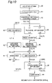
- FIG. 10 is a block diagram of a recording-medium reproducing apparatus in a second embodiment of the invention.
- FIG. 11 shows a conversion table in the NRZI transform unit in FIG. 10 ;
- FIG. 12 is a block diagram of the likelihood-transform RLL demodulator based on RLL(1, 7) in FIG. 10 ;
- FIG. 13 shows a demodulation table for determining post-demodulation data from channel data according to NRZI rules
- FIG. 14 shows a modulation table of RLL(1, 7) standardized by standard ECMA- 195 ;
- FIG. 15 shows a modulation table in which X's in FIG. 14 are developed to 0's and 1's;
- FIG. 16 is a block diagram of a recording-medium reproducing apparatus in a third embodiment of the invention.
- FIG. 17 shows an example of a trellis diagram of the PR-channel APP decoder in FIG. 16 ;
- FIG. 18 is a block diagram of a recording-medium reproducing apparatus in a fourth embodiment of the invention.
- FIG. 19 is a block diagram of a recording-medium reproducing apparatus in a fifth embodiment of the invention.
- FIG. 20 is a block diagram of a recording-medium reproducing apparatus in a sixth embodiment of the invention.
- FIG. 21 is a block diagram of a recording-medium reproducing apparatus in a seventh embodiment of the invention.
- FIG. 22 is a block diagram showing the constitution of an RLL demodulator in an eighth embodiment which performs demodulation by the likelihood transform method as a demodulation method of the invention.
- FIG. 23 is a block diagram of an RLL demodulator based on RLL (1, 7);
- FIG. 24 is a block diagram of an RLL demodulator based on RLL(1, 7) in a ninth embodiment of the invention.
- FIG. 25 is a configurational diagram of a recording and reproducing apparatus in a tenth embodiment of the invention, using the RLL demodulator shown in FIG. 23 or 24 ;
- FIG. 26 is a block diagram of an RLL demodulator in an eleventh embodiment of the invention, which performs demodulation by a likelihood transform method in which internal states are held;
- FIG. 27 is a block diagram of a background art recording and reproducing apparatus which performs coding and decoding processes of turbo code s;
- FIG. 28 is a block diagram of a background art recording and reproducing apparatus to which an RLL modulation method is applied.
- FIG. 29 is a block diagram of a background art RLL demodulator.
- FIG. 1 is a block diagram of a recording-medium reproducing apparatus of the present invention.
- FIG. 2 is a block diagram of a recording-medium recording apparatus which records, on a recording medium, channel data a i reproduced by the recording-medium reproducing apparatus shown in FIG. 1 .
- the recording-medium recording apparatus is explained.
- a convolutional coder 31 performs convolutional coding on inputted information data u i , outputting code data e i .
- An interleaver 32 performs pseudo-random substitution on the inputted code data e i ,outputting interleaved code data c i .
- An RLL modulator 33 performs RLL modulation on the inputted interleaved code data c i , outputting channel data a i .
- the channel data a i outputted in this way are recorded on a recording medium 35 by a recording circuit 34 .
- the recording circuit 34 implements the recording by magnetic recording, magneto-optical recording, optical recording or the like. Thus, this recording-medium recording apparatus performs both turbo coding and RLL modulation.
- a reproduction circuit 41 reproduces channel data recorded on the recording medium 35 , outputting a reproduced signal y′ i .
- the recording circuit 34 , the recording medium 35 and the reproduction circuit 41 which constitute a PR channel, have a property that adjacent pieces of channel data a i interfere with each other. Due to this, intersymbol interference has occurred to the reproduced signal y′ i .
- the reproduced signal y′ i when passing the PR channel, undergoes deformation such as noise addition, band limiting or crosstalk. Therefore, the reproduced signal y′ i has errors added therein.
- a logarithmic-likelihood computing circuit 42 serving as the probability computing means computes a logarithmic likelihood L(y′ i
- y i ) is then inputted to a code input terminal c;I of a PR-channel APP decoder 43 serving as the first APP decoding means. It is noted that contents of the computation by the logarithmic-likelihood computing circuit 42 will be described later.
- an output L(a′ i ;I) of a likelihood-transform RLL modulator 51 is inputted to an information input terminal u;I of the PR-channel APP decoder 43 .
- a logarithmic-likelihood ratio L(a′ i ;O) of channel data a′ i is outputted from the information output terminal u;O of the PR-channel APP decoder 43 .
- the PR-channel APP decoder 43 updates each likelihood in compliance with constraints concerning channel data a i and constraints concerning PR transfer characteristics.
- the constraints concerning channel data a i are RLL conditions.
- the code output terminal c;O from which the logarithmic likelihood L(y′ i
- a likelihood-transform RLL demodulator 44 performs RLL demodulation by a likelihood transform method serving as the probability transform method on the logarithmic-likelihood ratio L(a′ i ;O) of pre-demodulation channel data a′inputted from the PR-channel APP decoder 43 , outputting a logarithmic-likelihood ratio L(c′ i ;O) of post-modulation code data. It is noted that details of the RLL demodulation by the likelihood transform method will be described later.
- a subtracter 45 subtracts the output L(c′ i ;I) of an interleaver 50 from the logarithmic-likelihood ratio L(c′ i ;O) of the post-demodulation code data, outputting a subtraction result thereof as Lext(c′ i ). That is, the subtracter 45 operates immediately after the logarithmic-likelihood ratio L(c′ i ;O) is outputted from the likelihood-transform RLL demodulator 44 . Then, a logarithmic-likelihood ratio difference with respect to the code data c′ i updated by the PR-channel APP decoder 43 is calculated. This difference is called extrinsic information.
- a deinterleaver 46 performs an inverse substitution of the aforementioned pseudo-random substitution on the Lext(c′ i ) inputted from the subtracter 45 , outputting a logarithmic-likelihood ratio L(e′ i ;I) of deinterleaved (i.e., pre-interleaved) code data e′ i .
- L(e′ i ;I) the logarithmic-likelihood ratio L(e′ i ;I) derived from the deinterleaver 46 is inputted to a code input terminal c;I, while a zero is inputted to an information input terminal u;I.
- the logarithmic-likelihood ratio L(u′ i ;O) of the information data u′ i is outputted from an information output terminal u;O
- the logarithmic-likelihood ratio L(e′ i ;O) of the code data e′ i is outputted from a code output terminal c;O. That is, the convolutional-code APP decoder 47 updates each likelihood in compliance with constraints concerning convolutional codes.
- the logarithmic-likelihood ratio L(u′ i ;O) of the information data u′ i outputted from the information output terminal u;O of the convolutional-code APP decoder 47 is binarized by a comparator 48 and outputted as reconstructed information data u′ i .
- a subtracter 49 operates immediately after the logarithmic-likelihood ratio L(e′ i ;O) of code data e′ i is outputted from the code output terminal c;O of the convolutional-code APP decoder 47 . Then, upon receiving inputs of the logarithmic-likelihood ratio L(e′ i ;I) of the code data e′ i derived from the deinterleaver 46 and the logarithmic-likelihood ratio L(e′ i ; 0 ), the subtracter 49 subtracts the logarithmic-likelihood ratio L(e′ i ;I) from the logarithmic-likelihood ratio L(e′ i ;O), outputting a subtraction result Lext(e′ i ).
- the subtracter 49 computes a difference with respect to a logarithmic-likelihood ratio of the code data e′ i updated by the convolutional-code APP decoder 47 .
- This difference is also called extrinsic information.
- the interleaver 50 performs the pseudo-random substitution on the Lext(e′ i ) inputted from the subtracter 49 , outputting a logarithmic-likelihood ratio L(c′ i ;I) of the code data c′ i .
- the likelihood-transform RLL modulator 51 performs RLL modulation by the likelihood transform method on the logarithmic-likelihood ratio L(c′ i ;I) of inputted, pre-modulation code data c′ i , outputting a logarithmic-likelihood ratio L(a′ i ;I) of post-modulation channel data a′ i . It is noted that details of the RLL modulation by the likelihood transform method will be described later.
- the logarithmic-likelihood ratio L(a′ i ;I) of the channel data a′ i outputted from the likelihood-transform RLL modulator 51 is inputted to the information input terminal u;I of the PR-channel APP decoder 43 as described above.
- turbo decoding is performed by repeatedly delivering logarithmic-likelihood ratios between the PR-channel APP decoder 43 and the convolutional-code APP decoder 47 , allowing the reconstructed information data u′ i to be reduced in errors.
- a zero L(a′ i ;I) is inputted to the information input terminal u;I of the PR-channel APP decoder 43 .
- an ideal reproduced signal y i can be regarded as a signal train transmitted to a noise addition source.
- n i represents noise components added to the ideal reproduced signal y i .
- y i ) of the reproduced signal y′ i is defined as follows: L ( y′ i
- y i ) ln[ P ( y′ i
- ln represents a natural logarithm function.
- the logarithmic-likelihood computing circuit 42 can obtain the logarithmic-likelihood ratio L(y′ i ) of the reproduced signal y′ i .
- the logarithmic-likelihood computing circuit 42 may also be designed so as to output one value L(y′ i ) for each one received value y′i.
- the PR channel data y i results in one of four values, ⁇ 4, ⁇ 2, +2 and +4.
- the logarithmic-likelihood computing circuit 42 has only to compute the logarithmic likelihood L(y′ i
- y i ) (1 ⁇ 2 ⁇ n 2 )(2 y i y′ i ⁇ y i 2 )+Const i (8) where Const i , which is a constant value in four ways logarithmic likelihoods L(y′ i
- the logarithmic-likelihood computing circuit 42 in FIG. 1 receiving inputs of the reproduced signals y′ i from the recording medium 35 and the reproduction circuit 41 which form the PR channel, computes and outputs logarithmic likelihoods L(y′ i
- f 1 is a logical operation function for calculating the vector c′ t of m-bit code data from the vector a′ t of the received p-bit channel data.
- Tb denotes a data interval before modulation
- Tw denotes a detection window width. It is assumed that a symbol with a prime (′) indicates that the symbol is data reconstructed after reproduction, and a symbol without a prime (′) indicates that the symbol is data before recording.
- a number p of channel data bits targeted for the logical operation at a time is not less than the number n of post-modulation channel data bits.
- the pre-modulation code-data m bits are modulated into channel-data n bits. That is, before and after modulation, code-data m bits correspond to channel-data n bits.
- demodulation when p is equal to n, corresponding post-demodulation m bits are calculated from these channel-data n bits.
- post-demodulation m bits are calculated from p bits including preceding and succeeding bits of these n bits.
- the number of combinations of channel-data p bits is finite, its maximum being 2 P combinations including those not satisfying the RLL. Actually, there exists combinations not satisfying the RLL, so the number of cases is further smaller than 2 P . This number of combinations is assumed to be H. Then, the combinations of code-data m bits corresponding to the H combinations of channel-data p bits can preliminarily be determined. Therefore, each correspondence of these H combinations is expressed as (C h , A h ), where C h represents the “h”th combination of the code-data m bits and A h represents the “h”th combination of the channel-data p bits.
- code data after demodulation is demodulated to the vector C h .
- the unit of channel-data p bits before demodulation i.e., the vector a′ t
- post-demodulation code-data m bits are treated as one unit
- the unit of post-demodulation code-data m bits is referred to as a symbol.
- p is larger than n, a symbol before demodulation shares a bit or bits with its adjacent symbols.
- This correspondence (C h , A h ) among the H combinations is equivalent to the symbol correspondence rules between pre-demodulation and post-demodulation data expressed in a table.
- above Equation (10) is equivalent to the symbol correspondence rules between pre-demodulation and post-modulation data expressed in a logical expression. That is, the logical operation circuit that calculates the logical expression or the reference to ROM in which the rule table has previously been stored as a lookup table makes it possible to calculate post-demodulation code data c′ j,t from pre-demodulation channel data a′ k,t .
- the conventional RLL demodulator shown in FIG. 24 treats a′ k,t in above Equation (12) as binarized hard information.
- a′ k,t are treated as soft information. That is, a′ k,t are real numbers.
- likelihoods of a′ t and c′ t can be calculated by the following Equation (15).
- Equation (15) represents likelihoods for all the combinations of data trains before and after demodulation, i.e., likelihoods on the symbol-wise before and after demodulation.
- Equation (16) represents a total sum of H different values of P(c′ t
- c t C h ). It is noted that the denominator of Equation (16) is generally other than “1.” This is because the denominator does not include any combinations of channel data which do not satisfy the RLL. Equation (16) represents transform from likelihoods on a post-demodulation symbol-wise to likelihoods on a post-demodulation bit-wise.
- Equations (15) and (16) allow the transform from likelihoods on a pre-modulation bit-wise to likelihoods on a post-modulation bit-wise to be achieved. That is, first, by Equation (15), transform from pre-modulation bit-wise likelihoods to post-modulation symbol-wise likelihoods is performed. Next, by Equation (16), transform from post-demodulation symbol-wise likelihoods to post-demodulation bit-wise likelihoods is performed.
- L(c′ j, t ) when expressed with the likelihood P(c′ t
- c t C h ) of code data c t , can be determined from Equations (16) and (17) as shown by the following Equation (18):
- This Equation (18) is a transform equation from post-demodulation symbol-wise likelihoods to pre-modulation bit-wise logarithmic-likelihood ratios.
- L(a′ k ) of the channel data a k are defined as shown by the following Equation (20):
- Equation (21) is obtained from this Equation (20):
- D h, k is also defined similarly. That is, D h, k ⁇ 0,1 ⁇ since C h, k ⁇ 1 ⁇ .
- a h,k and C h, k can be determined in advance, so B h, k and D h, k can also be determined in advance.
- logarithmic-likelihood ratios L(c′ j, t ) of post-demodulation code data can be computed from the logarithmic-likelihood ratios L(a′ k, t ) of pre-demodulation channel data.
- g 1 is an arithmetic operation function for computing individual logarithmic-likelihood ratios of code-data m bits from individual logarithmic-likelihood ratios of reproduced channel data p bits.
- the transform from pre-demodulation bit-wise logarithmic-likelihood ratios L(a′ i ) to post-demodulation bit-wise logarithmic-likelihood ratios L(c′ i ) can be achieved by using symbol correspondence rules between pre- and post-demodulation data.
- transform from the bit-wise logarithmic-likelihood ratios L(c′ i ) of pre-modulation code data c′ i to the bit-wise logarithmic-likelihood ratios L(a′ i ) of post-demodulation channel data a′ i can be achieved by the likelihood-transform RLL modulator 51 described above.
- the constitution of the likelihood-transform RLL demodulator 44 for performing demodulation by the likelihood transform method as described above is described by way of a concrete example.
- FIG. 3 is a block diagram showing the constitution of the likelihood-transform RLL demodulator.
- Logarithmic-likelihood ratios L(a′ i ;O) of channel data a′ i outputted from the information output terminal u;O of the PR-channel APP decoder 43 (see FIG. 1 ) are inputted to a p-stage shift register 55 . Then, data are shifted by the p-stage shift register 55 at Tw intervals so that parallel data (L(a′ 1, t ), L(a′ 2, t ), . . . , L(a′ k, t ), . . .
- L(a′ p, t )) are outputted to an arithmetic operation circuit 56 .
- the arithmetic operation circuit 56 in turn performs arithmetic operations on the inputted parallel data (L(a′ 1, t ), L(a′ 2, t ), . . . , L(a′ k, t ), . . . , L(a′ p, t )) according to Equations (22) and (23). Then, the arithmetic operation circuit 56 outputs logarithmic-likelihood ratio parallel data (L(c′ 1, t ), L (c′ 2, t ), . . . , L(c′ j, t ), . . . , L(c′ m, t )) of post-demodulation code data to an m-stage shift register 57 equipped with a parallel load function.
- the m-stage shift register 57 loads in parallel the inputted logarithmic-likelihood ratio parallel data (L(c′ 1, t ), L(c′ 2, t ), . . . , L(c′ j, t ), . . . , L(c′ m, t )) of post-demodulation code data, and shifts the data at Tb intervals, outputting logarithmic-likelihood ratios L(c′ i ;O) of post-demodulation code data.
- the arithmetic operations by the arithmetic operation circuit 56 and the parallel loading by the m-stage shift register 57 are performed synchronously at (m ⁇ Tb) intervals.
- the p-stage shift register 55 and the m-stage shift register 57 are to hold real numbers.
- the logarithmic-likelihood computing circuit 42 that computes logarithmic likelihoods L(y′ i
- the likelihood-transform RLL demodulator 44 and the likelihood-transform RLL modulator 51 capable of treating logarithmic likelihoods, which are soft information as described above, are disposed before the convolutional-code APP decoder 47 .
- a recording-medium reproducing apparatus which performs both RLL demodulation and turbo decoding. That is, according to this embodiment, in reproducing channel data a i recorded on a recording medium by the recording-medium recording apparatus that performs both turbo coding and RLL modulation method shown in FIG. 2 , a turbo decoding of high error-correcting capability can be used. As a result, the recording density onto recording media can be enhanced as compared with cases where the PRML technique is used.
- FIG. 4 is a demodulation table of RLL(1, 7) standardized by standard ECMA-195 of the Standardizing Information and Communication Systems.
- a “1” of channel bits represents a polarity inversion of the reproduced signal
- a “0” of channel bits represents an obtainment of the same polarity as the preceding bit (i.e., preceding-polarity holding).
- Such a signal is referred to as a signal based on the NRZI rules.
- FIG. 5 is a demodulation table of the 1st to 34th combinations out of them. Also, FIG.
- FIG. 7 shows a block diagram of a likelihood-transform RLL demodulator based on RLL(1, 7).
- Logarithmic-likelihood ratios L(a′i;O) outputted from the PR-channel APP decoder 43 (see FIG. 1 ) are inputted to an 8-stage shift register 61 .
- the logarithmic-likelihood ratios L(a′ i ;O) are shifted at Tw intervals in this 8-stage shift register 61 , so that parallel data (L(a′ 1, t ), L(a′ 2, t ), . . . , L(a′ k, t ), . . . , L(a′ 8, t )) are outputted.
- An arithmetic operation circuit 62 performs arithmetic operations based on Equations (22) and (23) with the parallel data (L(a′ 1, t ), L(a′ 2, t ), . . . , L(a′ k, t ), . . . , L(a′ 8, t )), outputting logarithmic-likelihood ratio parallel data (L(c′ 1, t ),L(c′ 2, t )) of post-demodulation code data.
- the contents of arithmetic operations for RLL(1, 7) will be described later.
- a 2-stage shift register 63 with a parallel load function loads in parallel the logarithmic-likelihood ratio parallel data (L(c′ 1, t ),L(c′ 2, t )) of post-demodulation code data, and shifts the data at Tb intervals, outputting logarithmic-likelihood ratios L(c′ i ;O) of post-demodulation code data.
- exp(N h ) in Equation (24) corresponds to the “h”th row in the demodulation table shown in FIGS.
- D 1, 1 0 from the demodulation table ( FIG.
- exp(N 1 ) become elements of the total sum of the denominator in Equation (24).
- D 31, 1 1 from the demodulation table ( FIG. 5 )
- exp(N 31 ) become elements of the total sum of the numerator in Equation (24).
- Equation (24) the total sum of the denominator in Equation (24) is calculated based on exp(N 1 ), . . . , exp(N 30 ), exp(N 43 ), . . . , exp(N 48 ), and the total sum of the numerator is calculated based on exp(N 31 ), . . . , exp(N 42 ), exp(N 49 ), . . . , exp(N 68 ) Finally, L(c′ 1, t ) is calculated by Equation (24).
- L(c′ 2, t ) can also be calculated in the same manner, and thus the contents of arithmetic operations by the arithmetic operation circuit 62 are specifically determined. That is, the arithmetic operation circuit 62 performs arithmetic operations based on Equations (25), (26) and (24), thereby outputting logarithmic-likelihood ratio parallel data (L(c′ 1, t ),L(C′ 2, t )) of post-demodulation code data.
- Equation (24) can be simplified in terms of computation contents by approximation as shown by Equation (27):
- Equation (27) arithmetic operations for the exponential function “exp” and the natural logarithm function “ln” can be omitted, and logarithmic-likelihood ratio parallel data (L(c′ 1, t ),L(c′ 2, t )) of post-demodulation code data can be calculated only by the additions for calculating individual N h 's, the comparisons for determining maximum values, and the final subtraction. Accordingly, the arithmetic operations of the arithmetic operation circuit 62 can be simplified to a large extent.
- the arithmetic operation circuit in the likelihood-transform RLL modulator based on the RLL(1, 7) is also enabled to compute post-modulation bit-wise logarithmic-likelihood ratios L(a′ k, t ) from pre-modulation bit-wise logarithmic-likelihood ratios L(c′ j, t ) in a similar fashion according to the demodulation table shown in FIG. 4 . That is, the demodulation table shown in FIG. 4 may be exploited as a modulation table. However, in this case, since internal states are to be held within the likelihood-transform RLL modulator, the arithmetic operation circuit is to perform arithmetic operations according to Equations (36) and (40), which will be described later.
- FIG. 8 shows an example of a trellis diagram necessary for the PR-channel APP decoder 43 to achieve APP decoding in the case where the RLL modulation method by the likelihood-transform RLL demodulator 44 and the likelihood-transform RLL modulator 51 in FIG. 1 is RLL(1, 7) and where the PR transfer characteristic in the PR channel composed of the recording circuit 34 , the recording medium 35 and the reproduction circuit 41 is (1,2,1).
- this PR transfer characteristic (1,2,1) the relationship between PR channel data Y 1 and channel data a 1 is as shown in Equation (7).
- This Equation (7) corresponds to the constraints concerning PR transfer characteristics.
- the trellis diagram shown in FIG. 8 has four internal states of S 0 , S 1 , S 2 and S 3 .
- the numerator represents the channel data a i
- the denominator represents the PR channel data y i .
- S 3 For example, given an internal state S 3 at the time point “i,” if the PR channel data y i is “2,” then the channel data a i is “ ⁇ 1,” and the internal state at the next time point “i+1” is S 2 .
- the PR-channel APP decoder 43 may appropriately perform APP decoding according to this trellis diagram.
- the logarithmic-likelihood RLL demodulator 44 shown in FIG. 3 performs RLL demodulation only from p bits of inputted channel data as described above.
- the logarithmic-likelihood RLL demodulator 44 and the logarithmic-likelihood RLL modulator 51 shown in FIG. 1 allow a demodulation method in which internal states are held and a modulation method in which internal states are held to be applied thereto as well.
- a logarithmic-likelihood RLL demodulation method in which internal states are held within the demodulator is described below.
- f 3 represents a logical operation function for computing the succeeding internal states s′ t+1 from the received p-bit channel data a′ t and the current q-bit internal states s′ t .
- Part or all of the bits of the succeeding internal states s′ t+1 may be identical to part or all of the bits of the reconstructed code-data c′ t .
- the post-demodulation code data c′ 1,t ⁇ 1 which have been reconstructed immediately before, are also referred to in the demodulation of the channel data a′ t .
- demodulation is performed based on Equations (28) and (30).
- Equations (28) and (30) it is possible to input a′ k, t as soft information and output c′ k, t as soft information, as shown below.
- Equations (28) and (30) are expressed by the following Equations (33) to (35).
- D′′ h, k is also defined similarly. That is, D′′ h, k ⁇ 0,1 ⁇ since C′′ h, k ⁇ 1 ⁇ .
- A′′ h,k and C′′ h, k can be determined in advance, so B′′ h, k and D′′ h, k can also be determined in advance.
- c j , t + 1 ) P ⁇ ( c j , t ′
- c j , t - 1 ) ⁇ w ⁇ ⁇ h ⁇ ⁇ e ⁇ ⁇ r ⁇ ⁇ e ⁇ ⁇ 1 ⁇ j ⁇ m , ⁇ ln ⁇ P ⁇ ( s l , t + 1 ′
- s l , t + 1 + 1 ) P ⁇ ( s l , t + 1 ′
- s l , t + 1 - 1 ) ⁇ ( s l , t + 1 ′
- s l , t + 1 - 1 ) ⁇ w ⁇
- logarithmic-likelihood ratios L(c′ j, t ) of post-demodulation code data can be computed from the logarithmic-likelihood ratios L(a′ k, t ) of pre-demodulation channel data by using the symbol correspondence rules among pre-modulation and post-modulation data, the current internal states and the succeeding internal states.
- transform from the bit-wise logarithmic-likelihood ratios L(c′ i ) of pre-modulation code data c′ i to the bit-wise logarithmic-likelihood ratios L(a′ i ) of post-modulation channel data a′ i can be achieved by the likelihood-transform RLL modulator 51 described above in the modulation method in which internal states are held within the modulator.
- the likelihood-transform RLL demodulator 44 for performing demodulation by the likelihood transform method in which internal states are held within the demodulator as described above is described below.
- FIG. 9 is a block diagram in the case where the likelihood-transform RLL demodulator 44 is a likelihood-transform RLL demodulator using the likelihood transform method in which internal states are held within the demodulator.
- Logarithmic-likelihood ratios L(a′ i ;O) of channel data a′ i outputted from the information output terminal u;O of the PR-channel APP decoder 43 are inputted to a p-stage shift register 71 . Then, data are shifted by the p-stage shift register 71 at Tw intervals so that parallel data (L(a′ 1, t ), L(a′ 2, t ), . . . , L(a′ k, t ), .
- L(a′ p, t )) are outputted to an arithmetic operation circuit 72 .
- the arithmetic operation circuit 72 in turn performs arithmetic operations on the inputted parallel data (L(a′ 1, t ), L(a′ 2, t ), . . . , L(a′ k, t ), . . . , L(a′ p, t )) and individual q-bit logarithmic-likelihood ratios (L(s′ 1, t ), L(s′ 2, t ), . . . , L(s′ 1, t ), . . . .
- the arithmetic operation circuit 72 outputs logarithmic-likelihood ratio parallel data (L(c′ 1, t ), L(c′ 2, t ), . . . , L(c′ j, t ), . . . , L(c′ m, t )) of post-demodulation code data and individual q-bit logarithmic-likelihood ratios (L(s′ 1, t+1 ), L(s′ 2, t+1 ), . . . , L(s′ 1, t+1 ), . . . , L(s′ q, t+1 )) representing the succeeding internal states.
- An m-stage shift register 73 equipped with a parallel load function loads in parallel the logarithmic-likelihood ratio parallel data (L(c′ 1, t ), L(c′ 2, t ), . . . , L(c′ j, t ), . . . , L(c′ m, t )) of post-demodulation code data derived from the arithmetic operation circuit 72 , and shifts the data at Tb intervals, outputting logarithmic-likelihood ratios L(c′ i ) of post-demodulation code data. Also, the logarithmic-likelihood ratios (L(s′ 1, t+1 ), L(s′ 2, t+1 ), . .
- L(s′ q, t+1 )) representing the succeeding internal states and derived from the arithmetic operation circuit 72 are inputted to registers 74 a , 74 b , . . . , 74 d , respectively. It is noted that the registers 74 a , 74 b , 74 d correspond to the bits representing internal states, respectively. Therefore, the total number of the registers 74 a , 74 b , . . . , 74 d is q.
- the register 74 a loads, and holds, the first logarithmic-likelihood ratio L(s′ 1, t+1 ) of the succeeding internal states at (m ⁇ Tb) intervals, and outputs the first logarithmic-likelihood ratio L(s′ 1, t+1 ) of the current internal states at the next time point to the arithmetic operation circuit 72 .
- the other registers 74 b , . . . , 74 d also load and hold the second, . . . , “q”th logarithmic-likelihood ratios L(s′ 2, t+1 ), . . .
- Equation (36) the simplified method in which the computations of the exponential function “exp” and the natural logarithm function “1n” are omitted can be applied to Equation (36) also in the case of the likelihood-transform RLL demodulator using the likelihood transform method in which internal states are held within the demodulator, as in the case of the likelihood-transform RLL demodulator using the likelihood transform method based solely on inputted channel-data p bits.
- arithmetic processing by the arithmetic operation circuit 72 can be simplified.
- transform from the bit-wise logarithmic-likelihood ratios L(c′ i ) of pre-modulation code data c′ i to the bit-wise logarithmic-likelihood ratios L(a′ i ) of post-modulation channel data a′ i can be achieved by the likelihood transform method in which internal states are held within the modulator.
- the p-stage shift registers 55 , 71 , the m-stage shift registers 57 , 73 and the registers 74 a – 74 d are to hold real numbers.
- These real numbers may be numbers quantized with floating-point precision or fixed-point precision, and furthermore may be numbers of integer precision.
- the floating-point precision, the fixed-point precision and the integer precision are ranked in terms of arithmetic precision, higher to lower, in this order.
- logarithmic-likelihood ratios are used as likelihoods to be inputted or outputted by individual blocks. The reason of this is that using logarithmic-likelihood ratios allows the computing amount to be reduced.
- the present invention is not limited to logarithmic-likelihood ratios, and as an example, probability values may be inputted or outputted, as they are, by individual blocks.
- the subtracters 45 , 49 in FIG. 1 should be replaced with dividers.
- the convolutional code suitable for the turbo code method is used as the error-correcting code.
- the present invention is not limited to the convolutional code, and any error-correcting code capable of soft-information input and soft-information output decoding process will do.
- the convolutional coder 31 in FIG. 2 should be replaced with an error-correcting coder
- the convolutional-code APP decoder 47 in FIG. 1 should be replaced with an APP decoder for error-correcting codes.
- the modulation method is not limited to the RLL modulation. Any modulation method and demodulation method based on symbol correspondence rules between pre-modulation and post-modulation data and between pre-demodulation and post-demodulation data, or any modulation method and demodulation method based on correspondence rules between pre-modulation and post-modulation data as well as symbols of current internal states, and post-modulation and post-demodulation data as well as symbols of succeeding internal states, will do for implementation of the modulator and the demodulator using the likelihood transform method.
- time invariant demodulation system means that the function of Equation (10) or (33) does not vary with respect to the time point “t.”
- the present invention is applicable also to time variant demodulation methods.
- the time variant demodulation method means that the function of Equation (10) or (33) varies with respect to time point “t.”
- the function for performing likelihood transform may be varied in correspondence to variations of the function of Equation (10) or (33). That is, the function of Equation (23) or (40) may be varied on a time-point basis.
- a likelihood-transform RLL modulator using the likelihood transform method can also be implemented in the same manner as described above.
- an error-correcting coder may be provided for outer codes in addition to the convolutional coder 31 serving for inner codes. Also, additionally providing an interleaver between the error-correcting coder for outer codes and the convolutional coder 31 for inner codes allows the error rate to be further reduced. In this case, in a recording-medium reproducing apparatus corresponding to this, the deinterleaver and error-correcting-code APP demodulator should be connected, in this order, to the information output terminal u;O of the convolutional-code decoder 47 .
- FIG. 10 shows a block diagram of a recording-medium reproducing apparatus in a second embodiment of the invention.
- a reproduction circuit 81 a logarithmic-likelihood computing circuit 82 , a PR-channel APP decoder 83 , a subtracter 86 , a deinterleaver 87 , a convolutional-code APP decoder 88 , a comparator 89 , a subtracter 90 and an interleaver 91 are similar to the reproduction circuit 41 , the logarithmic-likelihood computing circuit 42 , the PR-channel APP decoder 43 , the subtracter 45 , the deinterleaver 46 , the convolutional-code APP decoder 47 , the comparator 48 , the subtracter 49 and the interleaver 50 , respectively, in the recording-medium reproducing apparatus shown in FIG. 1 in the first embodiment.
- An NRZI converter 84 to which logarithmic-likelihood ratios L(a′ i ;O) of channel data a′ i outputted from the information output terminal u;O of the PR-channel APP decoder 83 are inputted, computes and outputs logarithmic-likelihood ratios L(z′ i ;O) of channel data z′ i based on the NRZI rules at Tw intervals.
- a likelihood-transform RLL demodulator 85 performs RLL demodulation by the likelihood transform method on the inputted logarithmic-likelihood ratios L(z′ i ;O) of channel data z′ i before demodulation based on the NRZI rules, outputting logarithmic-likelihood ratios L(c′ i ;O) of post-demodulation code data c′ i .
- the outputted logarithmic-likelihood ratios L(c′ i ;O) are inputted to the subtracter 86 .
- a likelihood-transform RLL modulator 92 to which logarithmic-likelihood ratios L(c′ i ;I) of pre-modulation code data c′ i derived from an interleaver 91 are inputted, computes and outputs logarithmic-likelihood ratios L(z′ i ;I) of channel data z′ i based on the NRZI rules.
- An NRZ converter 93 to which these logarithmic-likelihood ratios L(z′ i ;I) are inputted, computes and outputs logarithmic-likelihood ratios L(a′ i ;I) of the channel data a′ i .
- the outputted logarithmic-likelihood ratios L(a′ i ;I) are inputted to the information input terminal u;I of the PR-channel APP decoder 83 .
- the combination of the NRZI converter 84 and the likelihood-transform RLL demodulator 85 offers the same functions as the likelihood-transform RLL demodulator 44 of the first embodiment.
- the combination of the likelihood-transform RLL modulator 92 and the NRZ converter 93 offers the same functions as the likelihood-transform RLL modulator 51 of the first embodiment.
- only the likelihood-transform RLL demodulator 44 of the first embodiment may be replaced with the NRZI converter 84 and the likelihood-transform RLL demodulator 85 .
- only the likelihood-transform RLL modulator 51 of the first embodiment may be replaced with the likelihood-transform RLL modulator 92 and the NRZ converter 93 .
- the NRZI converter 84 to which logarithmic-likelihood ratios L(a′ i ;O) of channel data a′ i are inputted, computes and outputs logarithmic-likelihood ratios L(z′ i ;O) of channel data z′ i according to the NRZI rules at Tw intervals.
- a “+1” of a channel bit z represents a polarity inversion of the reproduced signal
- a “ ⁇ 1” of a channel bit z i represents an obtainment of the same polarity of the reproduced signal as the preceding bit, i.e.
- FIG. 11 A conversion table of the NRZI converter 84 is shown in FIG. 11 .
- the polarity is inverted, so that the channel bit z i results in a “+1.”
- a i - 1 + 1 ) ⁇ P ⁇ ( a i ′
- a i - 1 ) + P ⁇ ( a i - 1 ′
- a i - 1 - 1 ) ⁇ P ⁇ ( a i ′
- FIG. 12 is a block diagram showing a concrete constitution of the likelihood-transform RLL demodulator 85 in the case of RLL(1, 7).
- Logarithmic-likelihood ratios L(z′ i ;O) outputted from the NRZI converter 84 are inputted to a 7-stage shift register 101 .
- data are shifted by the 7-stage shift register 101 at Tw intervals so that parallel data (L(z′ 1, t ), L(z′ 2, t ), . . . , L(z′ k, t ), . . .
- An arithmetic operation circuit 102 performs arithmetic operations on the parallel data (L(z′ 1, t ), L(z′ 2, t ), . . . , L(z′ k, t ), . . . , L(z′ 7, t )), outputting logarithmic-likelihood ratio parallel data (L(c′ 1, t ),L(c′ 2, t )) of post-demodulation code data. It is noted that contents of arithmetic operations in the case of RLL(1, 7) will be described later.
- a 2-stage shift register 103 equipped with the parallel load function loads in parallel the logarithmic-likelihood ratio parallel data (L(c′ 1, t ), L(c′ 2, t )) of post-demodulation code data, and shifts the data at Tb intervals, outputting logarithmic-likelihood ratios L(c′ i ) of post-demodulation code data.
- These arithmetic operations and parallel loading are performed synchronously at (2 ⁇ Tb) intervals.
- FIG. 13 shows a demodulation table for determining post-demodulation data from channel data based on the NRZI rules.
- Equation (22) the arithmetic operations of Equation (22) should be performed under the condition that the symbol z′ i of channel data based on the NRZI rules to be inputted to the arithmetic operation circuit 102 is formally replaced with a′ i .
- the channel bits z′ i come in 34 combinations. This number is one half of the number of combinations, 68 , for the likelihood-transform RLL demodulator 44 in the recording-medium reproducing apparatus that does not use the NRZI converter shown in FIG. 1 .
- the computing amount and the computing time can be reduced.
- the NRZ converter 93 to which logarithmic-likelihood ratios L(z′ i ;I) of channel data z′ i based on the NRZI rules are inputted at Tw intervals, computes and outputs logarithmic-likelihood ratios L(a′ i ;I) of channel data a′ i .
- the conversion table for the NRZI converter 84 shown in FIG. 11 can be utilized as it is as the conversion table for the NRZ converter 93 .
- the NRZ converter 93 to which logarithmic-likelihood ratios L(z′ i ) are inputted, holds L(a i ⁇ 1 ) as internal states and outputs logarithmic-likelihood ratios L(a′ i ).
- L(a′ i ) of channel data a′ i in this case are calculated by the following Equation (43):
- L ⁇ ( a i ′ ) ln ⁇ P ⁇ ( a i - 1 ′
- a i - 1 + 1 ) ⁇ P ⁇ ( z i ′
- z i - 1 ) + P ⁇ ( a i - 1 ′
- a i - 1 - 1 ) ⁇ P ⁇ ( z i ′
- z i + 1 ) P ⁇ ( a i - 1 ′
- a i - 1 - 1 ) ⁇ P ⁇ ( z i ′
- z i - 1 ) + P ⁇ ( a i - 1 ′
- a i - 1 + 1 ) ⁇ P ⁇ ( a i - 1 ′
- a i - 1 + 1 ) ⁇
- FIG. 14 shows a modulation table of RLL(1, 7) standardized by ECMA-195 as described before. It is noted that FIG. 14 is expressed in channel bits based on the NRZI rules.
- the likelihood-transform RLL modulator 92 is enabled to calculate post-modulation 3-bit channel data from pre-modulation 4-bit code data by looking up to this table. In this calculation, one bit equal to channel data that has been modulated immediately before needs to be held as the internal state.
- FIG. 15 shows a modulation table in which X's in FIG. 14 are developed to 0's and 1's.
- B′′ h, 4 is a succeeding internal state of 1 bit.
- L(a′′ k, t ) of code data a′′ j,t in the modulation based on the above modulation table are as shown by the following Equation (44):
- exp(N h ) in Equation (44) corresponds to the “th”th row in the modulation table shown in FIG. 15 .
- modulation table shown in FIG. 15 as a demodulation table allows the computations of the arithmetic operation circuit in the likelihood-transform RLL demodulator 85 to be implemented.
- the NRZI converter 84 that receives inputs of logarithmic-likelihood ratios L(a′ i ;O) and produces outputs of logarithmic-likelihood ratios L(z′ i ;O) of channel data z′ i based on the NRZI rules is disposed between the PR-channel APP decoder 83 , which is one of the two APP decoders constituting the turbo decoder, and the likelihood-transform RLL demodulator 85 .
- the NRZ converter 93 that receives inputs of logarithmic-likelihood ratios L(z′ i ;I) based on the NRZI rules and produces outputs of logarithmic-likelihood ratios L(a′ i ;I) of channel data a′ i is disposed between the likelihood-transform RLL modulator 92 and the PR-channel APP decoder 83 .
- the likelihood-transform RLL demodulator 85 has no need of performing NRZI conversion based on the NRZI rules, and the likelihood-transform RLL modulator 92 has no need of performing NRZ conversion based on the NRZI rules. Consequently, computing amount and computing time of the likelihood-transform RLL demodulator 85 and the likelihood-transform RLL modulator 92 can be considerably reduced, compared with those of the likelihood-transform RLL demodulator 44 and the likelihood-transform RLL modulator 51 in the first embodiment.
- FIG. 16 shows a block diagram of a recording-medium reproducing apparatus in a third embodiment.
- a reproduction circuit 111 , a logarithmic-likelihood computing circuit 112 , a subtracter 115 , a deinterleaver 116 , a convolutional-code APP decoder 117 , a comparator 118 , a subtracter 119 and an interleaver 120 are similar to the reproduction circuit 41 , the logarithmic-likelihood computing circuit 42 , the subtracter 45 , the deinterleaver 46 , the convolutional-code APP decoder 47 , the comparator 48 , the subtracter 49 and the interleaver 50 , respectively, of the recording-medium reproducing apparatus shown in FIG.
- a likelihood-transform RLL demodulator 114 and a likelihood-transform RLL modulator 121 are similar to the likelihood-transform RLL demodulator 85 and the likelihood-transform RLL modulator 92 of the recording-medium reproducing apparatus shown in FIG. 10 in the second embodiment.
- y i ) of a reproduced signal y′ i derived from the logarithmic-likelihood computing circuit 112 are inputted to a code input terminal c;I, and logarithmic-likelihood ratios L(z′ i ;I) of channel data z i based on the NRZI rules, which are outputs of the likelihood-transform RLL modulator 121 , are inputted to an information input terminal u;I.
- logarithmic-likelihood ratios L(z′ i ;O) of channel data z i based on the NRZI rules are outputted from an information output terminal u;O. It is noted that the code output terminal c;O, from which the logarithmic likelihoods L(y′ i ;O) of the PR channel data y′ i are outputted, is connected to none.
- FIG. 17 shows a trellis diagram necessary for the PR-channel APP decoder 113 to achieve APP decoding in the case where the RLL modulation method by the likelihood-transform RLL demodulator 114 and the likelihood-transform RLL modulator 121 in FIG. 16 is RLL(1, 7) and where the PR transfer characteristic in the PR channel composed of the recording circuit 34 , the recording medium 35 and the reproduction circuit 111 is (1,2,1).
- the trellis diagram shown in FIG. 17 has four internal states of S 0 , S 1 , S 2 and S 3 .
- the numerator represents the channel data z i based on the NRZI rules and the denominator represents the PR channel data y i .
- the PR-channel APP decoder 113 may appropriately perform APP decoding according to this trellis diagram.
- the PR transfer characteristic of this PR-channel APP decoder 113 is not limited to the above shown (1, 2, 1). Any PR transfer characteristic suitable for the recording medium may be applied as the PR transfer characteristic for the recording-medium reproducing apparatus of the invention.
- the PR-channel APP decoder 113 which is one of the two APP decoders constituting the turbo decoder, has an APP decoding function of receiving inputs of logarithmic likelihoods L(y′ i
- the likelihood-transform RLL demodulator 114 has no need of performing NRZI conversion based on the NRZI rules, and the likelihood-transform RLL modulator 121 has no need of performing NRZ conversion based on the NRZI rules. Consequently, computing amount and computing time of the likelihood-transform RLL demodulator 114 and the likelihood-transform RLL modulator 121 can be considerably reduced, compared with those of the likelihood-transform RLL demodulator 44 and the likelihood-transform RLL modulator 51 in the first embodiment.
- FIG. 18 shows a block diagram of a recording-medium reproducing apparatus in a fourth embodiment of the invention.
- a reproduction circuit 131 a logarithmic-likelihood computing circuit 132 , a PR-channel APP decoder 133 , a likelihood-transform RLL demodulator 135 , a deinterleaver 136 , a convolutional-code APP decoder 137 , a comparator 138 , a subtracter 139 , an interleaver 140 and a likelihood-transform RLL modulator 141 are similar to the reproduction circuit 41 , the logarithmic-likelihood computing circuit 42 , the PR-channel APP decoder 43 , the likelihood-transform RLL demodulator 44 , the deinterleaver 46 , the convolutional-code APP decoder 47 , the comparator 48 , the subtracter 49 , the interleaver 50 and the likelihood-transform RLL modulator 51 , respectively, in the recording-medium reproduc
- the subtracters 45 , 86 , 115 in the first to third embodiments are so designed to compute differences between logarithmic-likelihood ratios L(c′ i ;O) of code data c′ i derived from the likelihood-transform RLL demodulators 44 , 85 , 114 and logarithmic-likelihood ratios L(c′ i ;I) of code data c′ i derived from the interleavers 50 , 91 , 120 .
- the code data c′ i in this case are data after demodulation (i.e., before modulation).
- a subtracter 134 of this embodiment computes differences Lext(a′ i ) between logarithmic-likelihood ratios L(a′ i ;O) of channel data a′ i before demodulation (i.e., after modulation) derived from the PR-channel APP decoder 133 and logarithmic-likelihood ratios L(a′ i ;I) of channel data a′ i derived from the likelihood-transform RLL modulator 141 .
- the subtracter 134 operates immediately after the PR-channel APP decoder 133 has outputted logarithmic-likelihood ratios L(a′ i ;O). Then, as described above, the subtracter 134 subtracts logarithmic-likelihood ratios L(a′ i ;I), which are outputs of the likelihood-transform RLL modulator 141 , from the logarithmic-likelihood ratios L(a′ i ;O), outputting its subtraction results as Lext(a′ i ). The Lext(a′ i ) outputted in this way are inputted to the likelihood-transform RLL demodulator 135 . That is, the subtracter 134 calculates differences with respect to the logarithmic-likelihood ratios of channel data a′ i updated by the PR-channel APP decoder 133 .
- FIG. 19 shows a block diagram of a recording-medium reproducing apparatus in a fifth embodiment.
- a reproduction circuit 151 , a logarithmic-likelihood computing circuit 152 , a PR-channel APP decoder 153 , a likelihood-transform RLL demodulator 154 , a deinterleaver 155 , a convolutional-code APP decoder 157 , a comparator 158 , a subtracter 159 , an interleaver 160 and a likelihood-transform RLL modulator 161 are similar to the reproduction circuit 41 , the logarithmic-likelihood computing circuit 42 , the PR-channel APP decoder 43 , the likelihood-transform RLL demodulator 44 , the deinterleaver 46 , the convolutional-code APP decoder 47 , the comparator 48 , the subtracter 49 , the interleaver 50 and the likelihood-transform RLL modulator 51 , respectively, in the recording-medium reproducing
- a subtracter 156 operates immediately after the deinterleaver 155 has outputted logarithmic-likelihood ratios L(e′ i ;O 2 ) of code data e′ i . Then, the subtracter 156 subtracts logarithmic-likelihood ratios L(e′ i ;I 2 ) of code data e′ i , which are outputs of the subtracter 159 , from the logarithmic-likelihood ratios L(e′ i ;O 2 ), outputting its subtraction results as logarithmic-likelihood ratios L(e′ i ;I).
- the logarithmic-likelihood ratios L(e′ i ;I) outputted in this way are inputted to the code input terminal c;I of the convolutional-code APP decoder 157 . That is, the subtracter 156 calculates differences of the logarithmic-likelihood ratios of code data e′ i updated by the PR-channel APP decoder 133 .
- the subtracter 159 operates immediately after the convolutional-code APP decoder 157 has outputted logarithmic-likelihood ratios L(e′ i ;O) of code data e′ i . Then, the subtracter 159 subtracts logarithmic-likelihood ratios L(e′ i ;I), which are outputs of the subtracter 156 , from the logarithmic-likelihood ratios L(e′ i ;O), outputting its subtraction results as logarithmic-likelihood ratios L(e′ i ;I 2 ). The logarithmic-likelihood ratios L(e′ i ;I 2 ) outputted in this way are inputted to the interleaver 160 . That is, the subtracter 159 calculates differences with respect to the logarithmic-likelihood ratios of code data e′ i updated by the convolutional-code APP decoder 157 .
- the subtracter 45 , 134 , 156 has only to calculate the differences with respect to logarithmic-likelihood ratios (i.e., external information) updated by the PR-channel APP decoder 43 , 133 , 153 . Accordingly, the subtracter may well subtract the logarithmic-likelihood ratios of any one of channel data a′ i , code data c′ i and deinterleaved code data e′ i .
- the subtracter 86 in the second embodiment shown in FIG. 10 may subtract the logarithmic-likelihood ratios of any one of channel data a′ i , channel data z′ i based on the NRZI rules, code data c′ i and deinterleaved code data e′ i .
- the subtracter 115 in the third embodiment shown in FIG. 16 may subtract the logarithmic-likelihood ratios of any one of channel data z′ i based on the NRZI rules, code data c′ i and deinterleaved code data e′ i .
- the subtracter 49 , 90 , 119 , 139 , 159 in the first to fifth embodiments has only to calculate differences of the logarithmic-likelihood ratios (i.e., external information) updated by the convolutional-code APP decoder 47 , 88 , 117 , 137 , 157 . Accordingly, the subtracter may well subtract the logarithmic-likelihood ratios of any one of channel data a′ i , channel data z′ i based on the NRZI rules, code data c′ i and deinterleaved code data e′ i .
- FIG. 20 shows a block diagram of a recording-medium reproducing apparatus in a sixth embodiment.
- a reproduction circuit 171 , a logarithmic-likelihood computing circuit 172 , a PR-channel APP decoder 173 , a convolutional-code APP decoder 175 and a comparator 176 are similar to the reproduction circuit 41 , the logarithmic-likelihood computing circuit 42 , the PR-channel APP decoder 43 , the convolutional-code APP decoder 47 and the comparator 48 , respectively, in the recording-medium reproducing apparatus shown in FIG. 1 in the first embodiment.
- a converter 174 as the information conversion means receives, as inputs, logarithmic-likelihood ratios L(a′ i ;O) of channel data a′ i outputted from the information output terminal u;O of the PR-channel APP decoder 173 , and logarithmic-likelihood ratios L(e′ i ;O) of code data e′ i outputted from the code output terminal c;O of the convolutional-code APP decoder 175 .
- the converter 174 performs a first process of subjecting the logarithmic-likelihood ratios L(a′ i ;O) sequentially to demodulation by the likelihood transform method and deinterleaving, thereby outputting logarithmic-likelihood ratios L(e′ i ;I) of the code data e′ i . Also, the converter 174 performs a second process of subjecting the logarithmic-likelihood ratios L(e′ i ;O) sequentially to interleaving and modulation by the likelihood transform method, thereby outputting logarithmic-likelihood ratios L(a′ i ;I) of the code data a′ i .
- an intermediate result of the second process on the logarithmic-likelihood ratios L(e′ i ;O) is preliminarily subtracted from an intermediate result of the first process on the logarithmic-likelihood ratios L(a′ i ;O).
- an intermediate result of the first process on the logarithmic-likelihood ratios L(a′ i ;O) is preliminarily subtracted from an intermediate result of the second process on the logarithmic-likelihood ratios L(e′ i ;O).
- the converter 174 functions as the likelihood-transform RLL demodulator 44 , the subtracter 45 , the deinterleaver 46 , the subtracter 49 , the interleaver 50 and the likelihood-transform RLL modulator 51 in the first embodiment.
- FIG. 21 shows a block diagram of a recording-medium reproducing apparatus in a seventh embodiment.
- a reproduction circuit 181 , a logarithmic-likelihood computing circuit 182 , a PR-channel APP decoder 183 , a convolutional-code APP decoder 185 and a comparator 186 are similar to the reproduction circuit 111 , the logarithmic-likelihood computing circuit 112 , the PR-channel APP decoder 113 , the convolutional-code APP decoder 117 and the comparator 118 , respectively, in the recording-medium reproducing apparatus shown in FIG. 16 in the third embodiment.
- a converter 184 as the information conversion means receives, as inputs, logarithmic-likelihood ratios L(z′ i ;O) of channel data z′ i based on the NRZI rules outputted from the information output terminal u;O of the PR-channel APP decoder 183 , and logarithmic-likelihood ratios L(e′ i ;O) of code data e′ i outputted from the code output terminal c;O of the convolutional-code APP decoder 185 .
- the converter 184 performs a first process of subjecting the logarithmic-likelihood ratios L(z′ i ;O) sequentially to demodulation by the likelihood transform method and deinterleaving, thereby outputting logarithmic-likelihood ratios L(e′ i ;I) of the code data e′ i . Also, the converter 184 performs a second process of subjecting the logarithmic-likelihood ratios L(e′ i ;O) sequentially to interleaving and modulation by the likelihood transform method, thereby outputting logarithmic-likelihood ratios L(z′ i ;I) of the channel data z′ i based on the NRZI rules.
- an intermediate result of the second process on the logarithmic-likelihood ratios L(e′ i ;O) is preliminarily subtracted from an intermediate result of the first process on the logarithmic-likelihood ratios L(z′ i ;O).
- an intermediate result of the first process on the logarithmic-likelihood ratios L(z′ i ;O) is subtracted from an intermediate result of the second process on the logarithmic-likelihood ratios L(e′ i ;O).
- the converter 184 functions as the likelihood-transform RLL demodulator 144 , the subtracter 115 , the deinterleaver 116 , the subtracter 119 , the interleaver 120 and the likelihood-transform RLL modulator 121 in the third embodiment.
- This embodiment relates to an RLL demodulation method for performing demodulation by the likelihood transform method only from p bits (p: positive integer) of received channel data.
- An RLL demodulator for performing demodulation by the above-described likelihood transform method (see the first embodiment) is described below with respect to its constitution by referring to a concrete example thereof.
- FIG. 22 is a block diagram showing the constitution of an RLL demodulator which performs demodulation by the likelihood transform method.
- Channel data a′ i before demodulation reproduced from a recording medium serving as a channel are inputted to a logarithmic-likelihood ratio computing circuit 211 at Tw intervals. Then, logarithmic-likelihood ratios are computed by the logarithmic-likelihood ratio computing circuit 211 , and logarithmic-likelihood ratios L(a′ i ) of the pre-modulation channel data are outputted. Contents of the computations by the logarithmic-likelihood ratio computing circuit 211 in this process will be described later.
- the logarithmic-likelihood ratios L(a′ i ) of the channel data outputted from the logarithmic-likelihood ratio computing circuit 211 in this way are inputted to a p-stage shift register 212 . Then, data are shifted by the p-stage shift register 212 at Tw intervals so that parallel data (L(a′ 1, t ), L(a′ 2, t ), . . . , L(a′ k, t ), . . . , L(a′ p, t )) are outputted to an arithmetic operation circuit 213 .
- the arithmetic operation circuit 213 in turn performs arithmetic operations on the inputted parallel data (L(a′ 1, t ), L(a′ 2, t ), . . . , L(a′ k, t ), . . . , L(a′ p, t )) based on Equations (22) and (23). Then, the arithmetic operation circuit 213 outputs logarithmic-likelihood ratio parallel data (L(c′ 1, t ), L(c′ 2, t ), . . . , L(c′ j, t ), . . . , L(c′ m, t )) of post-demodulation code data to an m-stage shift register 214 (m: positive integer)equipped with a parallel load function.
- m positive integer
- the m-stage shift register 214 loads in parallel the inputted logarithmic-likelihood ratio parallel data (L(c 1, t ), L(C′ 2, t ), . . . , L(c′ j, t ), . . . , L(c′ m, t )) of post-demodulation code data, and shifts the data at Tb intervals, outputting logarithmic-likelihood ratios L(c′ i ) of post-demodulation code data.
- the arithmetic operations by the arithmetic operation circuit 213 and the parallel loading by the m-stage shift register 214 are performed synchronously at (m ⁇ Tb) intervals.
- the logarithmic-likelihood ratios are real numbers
- the p-stage shift register 212 and the m-stage shift register 214 are to hold real numbers.
- n i noise added to the channel data a i ,
- Lc constant determined by CNR (Carrier to Noise Ratio).
- the RLL demodulator in this embodiment has the logarithmic-likelihood ratio computing circuit 211 to which the pre-demodulation channel data a′ i reproduced from the channel (recording medium) are inputted at Tw intervals. Then, assuming that the channel is a white Gaussian channel, the logarithmic-likelihood ratios L(a′ i ) of channel data are computed and outputted by Equation (46). Further, the logarithmic-likelihood ratios L(a′ i ) of real numbers are shifted and transformed into parallel data by the p-stage shift register 212 .
- logarithmic-likelihood ratios parallel data of post-demodulation m-bit code data are calculated based on Equations (22) and (23) by the arithmetic operation circuit 213 .
- the post-demodulation parallel data are loaded in parallel by the m-stage shift register 214 with a parallel load function, and shifted at Tb intervals, so that logarithmic-likelihood ratios L(c′ i ) of post-demodulation code data are outputted.
- the post-demodulation code data outputted from the RLL demodulator in this embodiment are real values, and reconstructed code data, which is soft information, can be outputted to the succeeding-stage turbo decoder.
- turbo decoding is enabled so that the recording density onto recording media can be enhanced, as compared with cases where Viterbi decoders or the like, which are lower in error-correcting capability, are used.
- FIG. 23 shows a block diagram of an RLL demodulator by the likelihood transform method based on RLL(1, 7).
- the logarithmic-likelihood ratio computing circuit 221 computes and outputs logarithmic-likelihood ratios L(a′ i ) according to the Equation (46) based on a reproduced signal a′ i inputted at Tw intervals.
- the L(a′ i ) outputted from the logarithmic-likelihood ratio computing circuit 221 are inputted to an 8-stage shift register 222 . Then, data are shifted at Tw intervals in the 8-stage shift register 222 so that parallel data (L(a′ 1, t ), L(a′ 2, t ), . . . , L(a′ k, t ), . . . , L(a′ 8, t )) are outputted.
- An arithmetic operation circuit 223 in turn performs arithmetic operations based on Equations (22) and (23) with the inputted parallel data (L(a′ 1, t ), L(a′ 2, t ), . . .
- a 2-stage shift register 224 with a parallel load function loads in parallel the logarithmic-likelihood ratio parallel data (L(c′ 1, t ),L(c′ 2, t )) of post-demodulation code data, and shifts the data at Tb intervals, outputting logarithmic-likelihood ratios L(c′ i ) of post-demodulation code data.
- FIG. 24 shows a block diagram, different from FIG. 23 , of an RLL demodulator using the likelihood transform method based on RLL(1, 7).
- a logarithmic-likelihood ratio computing circuit 231 as described above, computes and outputs logarithmic-likelihood ratios L(a′ i ) according to the above Equation (46) based on a reproduced signal a′ i inputted at Tw intervals.
- An NRZI rule converter 232 receives inputs of the logarithmic-likelihood ratios L(a′ i ), and computes and outputs logarithmic-likelihood ratios L(z′ i ) of channel data z′ i based on the NRZI rules at Tw intervals.
- a “+1” of a channel bit z i based on the NRZI rules represents a polarity inversion of the reproduced signal
- a “ ⁇ 1” of a channel bit z i based on the NRZI rules represents an obtainment of the same polarity of the reproduced signal as the preceding bit, i.e.
- a conversion table of the NRZI rule converter 232 is as shown in FIG. 11 , as in the second embodiment.
- Logarithmic-likelihood ratios of the channel bits z i based on the NRZI rules can be calculated according to the foregoing Equation (41).
- the logarithmic-likelihood ratios L(z′ i ) outputted from the NRZI rule converter 232 are inputted to a 7-stage shift register 233 . Then, data are shifted at Tw intervals in the 7-stage shift register 233 so that parallel data (L(z′ 1, t ), L(z′ 2, t ), . . . , L(z′ k, t ), . . . , L(z′ 7, t )) are outputted.
- An arithmetic operation circuit 234 in turn performs arithmetic operations on the inputted parallel data (L(z′ 1, t ) L(z′ 2, t ), . . .
- a 2-stage shift register 235 with a parallel load function loads in parallel the logarithmic-likelihood ratio parallel data (L(c′ 1, t ), L(c′ 2, t )) of post-demodulation code data, and shifts the data at Tb intervals, outputting logarithmic-likelihood ratios L(c′ i ) of post-demodulation code data.
- These arithmetic operations and the parallel loading are performed synchronously at (2 ⁇ Tb) intervals.
- a demodulation table for determining post-demodulation data from channel data based on the NRZI rules is the same as the demodulation table shown in FIG. 13 and used in the second embodiment, and this demodulation table is as already explained.
- Equation (22) the arithmetic operations of Equation (22) should be performed under the condition that the symbol z′ i of channel data based on the NRZI rules to be inputted to the arithmetic operation circuit 234 is formally replaced with a′ i .
- the channel bits z′ i come in 34 combinations.
- the number of combinations is one half of the number of combinations, 68, for the RLL demodulator that does not use the NRZI converter shown in FIG. 23 , the computing amount and the computing time can be reduced.
- FIG. 25 is a schematic diagram showing the constitution of a recording and reproducing apparatus which implements the error-correcting method.
- a turbo coder 241 performs error-correcting coding on inputted information data u i , outputting code data c,.
- An RLL modulator 242 performs RLL modulation on the inputted code data c i , outputting channel data a i .
- the channel data a i outputted in this way are recorded on a recording medium 244 by a recording circuit 243 .
- the recording circuit 243 implements the recording by magnetic recording, magneto-optical recording, optical recording or the like.
- a reproduction circuit 245 reproduces the channel data a i recorded on the recording medium 244 , outputting the reproduced channel data a′ i .
- the channel data a′ i reproduced in this way have undergone deformation such as noise addition, band limiting, intersymbol interference or crosstalk depending on individual characteristics of the recording circuit 243 , the recording medium 244 and the reproduction circuit 245 . That is, in FIG. 25 , the recording circuit 243 , the recording medium 244 and the reproduction circuit 245 constitute a channel. As a result, the channel data a′ i reproduced from the recording medium 244 has errors added thereto.
- the likelihood-transform RLL demodulator 246 which is the likelihood-transform RLL demodulator shown in FIG.
- the turbo decoder 247 corrects the errors added by the channel in the inputted logarithmic-likelihood ratios L(c′ i ), thus outputting reconstructed information data u′ i .
- the likelihood-transform RLL demodulator 246 can output logarithmic-likelihood ratios L(c′ i ) of code data, which are soft information. Therefore, according to the recording and reproducing apparatus shown in FIG. 25 , the turbo decoding method can be applied even to cases where the RLL modulation is used. As a result, the recording density onto recording media can be enhanced as compared with cases where the Viterbi coding method, which is lower in error-correcting capability, is used.
- the RLL demodulation in the eighth to tenth embodiments is an RLL demodulation method in which demodulation is performed only from p bits of received channel data as described above.
- This demodulation by the likelihood transform method can also be applied to demodulation methods in which internal states are held within the demodulator.
- This embodiment relates to an RLL demodulation method in which internal states are held within the demodulator. The principle of such an RLL demodulation method has already been described in detail in the first embodiment and so its description is omitted here (see Equations (28) to (40)).
- FIG. 26 is a block diagram showing the constitution of an RLL demodulator that performs demodulation by the likelihood transform method in which internal states are held within the demodulator.
- a logarithmic-likelihood ratio computing circuit 251 receives inputs of pre-demodulation channel data a′ i reproduced from a recording medium serving as a channel at the Tw intervals. Then, the logarithmic-likelihood ratio computing circuit 251 computes logarithmic-likelihood ratios and outputs the logarithmic-likelihood ratios L(a′ i ) of pre-demodulation channel data.
- the logarithmic-likelihood ratios L(a′ i ) of channel data outputted from the logarithmic-likelihood ratio computing circuit 251 in this way are inputted to a p-stage (p: positive integer) shift register 252 . Then, data are shifted by the p-stage shift register 252 at Tw intervals so that parallel data (L(a′ 1, t ), L(a′ 2, t ), . . . , L(a′ k, t ), . . . , L(a′ p, t )) are outputted to an arithmetic operation circuit 253 .
- the arithmetic operation circuit 253 performs arithmetic operations on the inputted parallel data (L(a′ 1, t ), L(a′ 2, t ), . . . , L(a′ k, t ), . . . , L(a′ p, t )) as well as later-described logarithmic-likelihood ratios (L(s′ 1, t ), L(S′ 2, t ), . . . , L(s′ l, t ), . . . , L(s′ q, t )) of q bits (q: positive integer) representing current internal states based on Equations (36) and (40).
- the arithmetic operation circuit 253 outputs logarithmic-likelihood ratio parallel data (L(c′ 1, t ), L(c′ 2, t ), . . . , L(c′ j, t ), . . . , L(c′ m, t )) of post-demodulation code data as well as individual logarithmic-likelihood ratios (L(s′ 1, t+1 ) L(s′ 2, t+1 ), . . . , L(s′ l, t+1 ), . . . , L(s′ q, t+1 )) of q bits (q: Positive integer) representing succeeding internal states.
- An m-stage shift register 254 with a parallel load function loads in parallel the logarithmic-likelihood ratio parallel data (L(c′ 1, t ), L(c′ 2, t ), . . . , L(c′ j, t ), L(c′ m, t )) of post-demodulation code data derived from the arithmetic operation circuit 253 , and shifts the data at Tb intervals, outputting logarithmic-likelihood ratios L(c′ i ) of post-demodulation code data. Also, the logarithmic-likelihood ratios (L(s′ 1, t+1 ), L(S′ 2, t+1 ), . . .
- L(s′ q, t+1 )) representing succeeding internal states and derived from the arithmetic operation circuit 253 are inputted to registers 255 a , 255 b , . . . , 255 d , respectively.
- the registers 255 a , 255 b , . . . , 255 d correspond to the bits representing the internal states, respectively, hence the registers 255 a , 255 b , . . . , 255 d counting q as a total number of registers.
- the register 255 a loads, and holds, the first logarithmic-likelihood ratio L(s′ 1, t+1 ) of the succeeding internal states at (m ⁇ Tb) intervals.
- the register 255 a outputs the first logarithmic-likelihood ratio L(s′ 1, t ) of the current internal states at the next time point to the arithmetic operation circuit 253 .
- the other registers 255 b , . . . , 255 d also load and hold the second, . . . , “q”th logarithmic-likelihood ratios L(s′ 2, t+1 ), . . .
- logarithmic-likelihood ratios L(a′ i ) of pre-demodulation channel data inputted from the logarithmic-likelihood ratio computing circuit 251 are shifted and transformed into parallel data by the p-stage shift register 252 .
- the arithmetic operation circuit 253 performs arithmetic operations of Equations (36) and (40) on the parallel data derived from the p-stage shift register 252 and the individual logarithmic-likelihood ratios representing the current internal states derived from the registers 255 a to 255 d , thereby computing logarithmic-likelihood ratio parallel data of post-demodulation code data and logarithmic-likelihood ratios representing succeeding internal states.
- the post-demodulation parallel data are loaded in parallel, shifted at Tb intervals, by which logarithmic-likelihood ratios L(c′ i ) of post-demodulation code data are outputted.
- the individual logarithmic-likelihood ratios representing the succeeding internal states derived from the arithmetic operation circuit 253 are loaded and held at (m ⁇ Tb) intervals to the registers 255 a to 255 d . Then, at the next time point, the data are outputted to the arithmetic operation circuit 253 as logarithmic-likelihood ratios of the current internal states.
- the post-demodulation code data outputted from the RLL demodulator in this embodiment are real numbers, and reconstructed code data as soft information can be outputted to the succeeding-stage turbo decoder.
- use of an error-correcting decoder or the like of high error-correcting capability is enabled so that the recording density onto recording media can be enhanced.
- Equation (36) the simplified method in which the computations of the exponential function “exp” and the natural logarithm function “in” are omitted can be applied to Equation (36), as in the case of the eighth embodiment.
- arithmetic processing by the arithmetic operation circuit 253 can be simplified.
- the RLL demodulator of this embodiment may be used as the likelihood-transform RLL demodulator 246 in the recording and reproducing apparatus shown in FIG. 25 .
- the p-stage shift registers 212 , 222 , 233 , 252 , the m-stage shift registers 214 , 224 , 235 , 254 and the registers 255 a – 255 d are to hold real numbers.
- These real numbers may be numbers quantized with floating-point precision or fixed-point precision, and furthermore may be numbers of integer precision.
- the floating-point precision, the fixed-point precision and the integer precision are ranked in terms of arithmetic precision, higher to lower, in this order.
- turbo coding is used as the error-correcting coding.
- the present invention is not limited to this, and any error-correcting method of soft-information inputs will do.
- the turbo coder 241 in FIG. 25 may be replaced with an error-correcting coder
- the turbo decoder 247 may be replaced with an error-correcting decoder.
- the modulation method is not limited to the Run Length Limited modulation.
- the present invention is applicable to any modulation method based on symbol correspondence rules between post-demodulation data and pre-demodulation data, or to any modulation method based on correspondence rules between symbols of pre-demodulation data as well as current internal states and symbols of post-demodulation data as well as succeeding internal states.
- time invariant demodulation methods are used in the eighth to eleventh embodiments, this is not limitative. It is noted here that the time invariant demodulation method means that the function of Equation (10) or (33) does not vary with respect to the time point “t.” However, the present invention is applicable also to time variant demodulation methods. It is noted here that the time variant demodulation method means that the function of Equation (10) or (33) varies with respect to the time point “t.” In the case where a time variant demodulation method is applied, the function for performing likelihood transform may be varied in correspondence to variations of the function of Equation (10) or (33). That is, the function of Equation (22) or (40) may be varied on a time-point basis.
Abstract
Description
y′ i =y i +n i (1)
where yi is an ideal reproduced signal that is not affected by the channel, and
L(y′ i |y i)=ln[P(y′ i |y i)] (2)
where P(y′i|yi) is a conditional probability of reception of the reproduced signal y′i in transmission of a signal train yi. In addition, ln represents a natural logarithm function.
where, in Equation (4), an is an effective amplitude (standard deviation) of this noise. Also, exp is an exponential function. Then, from Equation (4), the logarithmic-likelihood ratio of the reproduced signal y′i can be calculated by the following Equation (5):
L(y′ i)=Lc·y′ i (5)
Lc=2/σn 2 (6)
Accordingly, by multiplying the inputted reproduced signal y′i by the constant Lc, the logarithmic-
y i =a i+2·a i−1 +a i−2 (7)
In this case, as described later, if the channel data ai is assumed to be either value of “+1” or “−1,” with the minimum run length limit (d=1) taken into consideration, the PR channel data yi results in one of four values, −4, −2, +2 and +4. Consequently, the logarithmic-
L(y′ i |y i)=(½σn 2)(2y i y′ i −y i 2)+Consti (8)
where Consti, which is a constant value in four ways logarithmic likelihoods L(y′i|yi), is determined so that a total of conditional probabilities P(y′i|yi ) at which four pieces of PR channel data yi are received becomes 1. However, since computation is performed in the PR-
L(y′ i |y i=+4)=(1/σn 2)(4y′ i−8)
L(y′ i |y i=+2)=(1/σn 2)(2y′ i−2)
L(y′ i |y i=−2)=(1/σn 2)(−2y′ i−2)
L(y′ i |y i=−4)=(1/σn 2)(−4y′ i−8) (9)
The logarithmic-
where the vector a′t represents channel-data p bits at a time point “t,” and the vector c′t represents reconstructed code-data m bits at the time point “It.” Further, a′k,t represents the “k”th bit within the vector a′t, and c′j,t represents the “j”th bit within the vector c′t. Furthermore, f1 is a logical operation function for calculating the vector c′t of m-bit code data from the vector a′t of the received p-bit channel data. The time point “t” represents a time sequence for calculation of Equation (10), the calculation being done every m×Tb=n×Tw interval in this RLL demodulation. It is noted that Tb denotes a data interval before modulation, and Tw denotes a detection window width. It is assumed that a symbol with a prime (′) indicates that the symbol is data reconstructed after reproduction, and a symbol without a prime (′) indicates that the symbol is data before recording.
When channel data belongs to the vector Ah, code data after demodulation is demodulated to the vector Ch. It is noted that Ah,k and Ch,j are constants, either “+1” or “−1,” and that h=1, 2, . . . , H. Further, since channel-data p bits before demodulation are treated as one unit, the unit of channel-data p bits before demodulation (i.e., the vector a′t) is referred to as a symbol. Likewise, since post-demodulation code-data m bits are treated as one unit, the unit of post-demodulation code-data m bits (i.e., the vector c′t) is referred to as a symbol. In addition, when p is larger than n, a symbol before demodulation shares a bit or bits with its adjacent symbols.
P(a′ k, t |a k, t=+1)=1−P(a′ k, t |a k, t=−1) (14).
It is noted that P(a′k, t|ak, t=+1) in Equation (14) is a conditional probability at which reproduced channel data become a′k,t under the condition that recorded channel data is “ak, t=+1.”
In Equation (15), P(c′t|ct=Ch) is a conditional probability at which reconstructed code data become c′t under the condition that the code data ct is Ch. Equation (15) represents likelihoods for all the combinations of data trains before and after demodulation, i.e., likelihoods on the symbol-wise before and after demodulation.
where the numerator in above Equation (16) represents a total sum of P(c′t|ct=Ch) only of Ch in which the code data Ch,j is equal to “+1” out of H different values of Ch. Also, the denominator represents a total sum of H different values of P(c′t|ct=Ch). It is noted that the denominator of Equation (16) is generally other than “1.” This is because the denominator does not include any combinations of channel data which do not satisfy the RLL. Equation (16) represents transform from likelihoods on a post-demodulation symbol-wise to likelihoods on a post-demodulation bit-wise.
where in represents a natural logarithm function. Therefore, L(c′j, t), when expressed with the likelihood P(c′t|ct=Ch) of code data ct, can be determined from Equations (16) and (17) as shown by the following Equation (18):
This Equation (18) is a transform equation from post-demodulation symbol-wise likelihoods to pre-modulation bit-wise logarithmic-likelihood ratios. Furthermore, the logarithmic-likelihood ratios L(c′j, t) of above Equation (18), when expressed with the likelihoods P(a′k, t|ak, t=+1) and P(a′k, t|ak, t=−1) of channel data ak, t, results in the following Equation (19) by the Equation (15):
This Equation (19) is a transform equation from pre-modulation bit-wise likelihoods to post-demodulation bit-wise logarithmic-likelihood ratios.
Then, the following Equation (21) is obtained from this Equation (20):
where
B h, k=(½)·(A h, k+1 )
D h, k=(½)·(C h, k+1 ),
that is, Bh, kε{0,1} since Ah, kε{±1}. Correspondingly to this, Dh, k is also defined similarly. That is, Dh, kε{0,1} since Ch, k{±1}. Thus, as Ah,k and Ch, k can be determined in advance, so Bh, k and Dh, k can also be determined in advance.
In Equation (22), it is apparent that the computation using Bh, k involves less computing amount than the computation using Ah,ks. This is because it is only for Bh, k=1 that the total summation of L(a′k, t) is to be done. Therefore, in order to reduce the computing amount and computing time for the RLL demodulation, the computation using Bh, k is more desirable.
(L(c′ 1, t),L(c′ 2, t), . . . , L(c′ j, t), . . . , L(c′ m, t))=g 1(L(a′ 1, t), L(a′ 2, t), . . . , L(a′ k, t), . . . , L(a′p, t)) (23)
where g1 is an arithmetic operation function for computing individual logarithmic-likelihood ratios of code-data m bits from individual logarithmic-likelihood ratios of reproduced channel data p bits.
where exp(Nh) in Equation (24) corresponds to the “h”th row in the demodulation table shown in
N 1 =L(a′ 2, t)+L(a′ 3, t)+L(a′ 4, t)+L(a′ 5, t)+L(a′ 6, t)+L(a′ 7, t)+L(a′ 8, t) (25)
Also, since D1, 1=0 from the demodulation table (
N 31 =L(a′ 5, t)+L(a′6, t)+L(a′ 7, t)+L(a′ 8, t) (26)
Also, since D31, 1=1 from the demodulation table (
where the first term of Equation (27) represents an Nh that is the largest of Nh′s with Dh, j=1. Likewise, the second term represents an Nh that is the largest of Nh's with Dh, j=0.
where the vector s′t represents current-internal-state q bits as shown by Equation (29):
It is noted that f2 represents a logical operation function for computing reconstructed code-data m bits c′t from reproduced p-bit channel data a′t and current q-bit internal states s′t.
The vector s′t+1 represents succeeding-internal-state q bits as shown by Equation (31):
It is noted that f3 represents a logical operation function for computing the succeeding internal states s′t+1 from the received p-bit channel data a′t and the current q-bit internal states s′t.
This means that the post-demodulation code data c′1,t−1, which have been reconstructed immediately before, are also referred to in the demodulation of the channel data a′t.
where c″t represents c′t and s′t+1, being of (m+q) bits. Similarly, a″t represents a′t and s′t, being of (p+q) bits.
Based on that
B″ h, k=(½)·(A″ h, k+1)
D″ h, k=(½)·(C″ h, k+1)
logarithmic-likelihood ratios L(c′j,t) of post-demodulation code data can be calculated from the logarithmic-likelihood ratios L(a′k, t) of pre-demodulation channel data.
where h=1, 2, . . . ,H″. This correspondence (C″h,A″h) among the H″ combinations is equivalent to the correspondence rules between symbols of pre-modulation data as well as current internal states, and symbols of post-modulation data as well as succeeding internal states, as they are expressed in tables. Also, the above Equation (33) is equivalent to the correspondence rules between symbols of pre-modulation data as well as current internal states, and symbols of post-modulation data as well as succeeding internal states, as they are expressed in logical expressions. By the logical operation circuit that computes the logical expressions, or by looking up as a table to the ROM in which the rule table has previously been stored, it becomes possible to calculate post-demodulation code data c′j,t from pre-modulation channel data a′k,t.
where g2 is an arithmetic operation function for computing individual logarithmic-likelihood ratios of code-data m bits and succeeding-internal-state q bits from individual logarithmic-likelihood ratios of reproduced channel-data p bits and current-internal-state q bits.
where P(a′i−1|a1−1+1) is a conditional probability at which reproduced channel data becomes a′i−1 under the condition that ai−1 at recording is “+1.”
where logarithmic-likelihood ratios L(a′i) calculated at a time point “i” are used as logarithmic-likelihood ratios L(ai−1) in the calculation at a time point “i+1.”
where exp(Nh) in Equation (44) corresponds to the “th”th row in the modulation table shown in
a′ i =a i +n i (45)
L(a′ i)=Lc·a′ i (46)
Claims (38)
Applications Claiming Priority (4)
| Application Number | Priority Date | Filing Date | Title |
|---|---|---|---|
| JP2001-119400 | 2001-04-18 | ||
| JP2001-119399 | 2001-04-18 | ||
| JP2001119399A JP2002313036A (en) | 2001-04-18 | 2001-04-18 | Demodulation method, error correction method, and recording medium reproducing device |
| JP2001119400A JP2002313035A (en) | 2001-04-18 | 2001-04-18 | Encoding method and recording medium, decoding method, and recording medium reproducing device |
Publications (2)
| Publication Number | Publication Date |
|---|---|
| US20030014714A1 US20030014714A1 (en) | 2003-01-16 |
| US6996764B2 true US6996764B2 (en) | 2006-02-07 |
Family
ID=26613761
Family Applications (1)
| Application Number | Title | Priority Date | Filing Date |
|---|---|---|---|
| US10/125,037 Expired - Fee Related US6996764B2 (en) | 2001-04-18 | 2002-04-18 | Coding method, recording medium, decoding method, and recording-medium reproducing apparatus |
Country Status (1)
| Country | Link |
|---|---|
| US (1) | US6996764B2 (en) |
Cited By (5)
| Publication number | Priority date | Publication date | Assignee | Title |
|---|---|---|---|---|
| US20020174400A1 (en) * | 2001-04-18 | 2002-11-21 | Eiji Yamada | Decoding method and recording-medium reproducing apparatus |
| US20040205446A1 (en) * | 2003-02-21 | 2004-10-14 | Hiroyuki Yamagishi | Decoding apparatus, decoding method, recording/reproducing apparatus, program storage medium, and program |
| US20050022095A1 (en) * | 2003-07-10 | 2005-01-27 | Samsung Electronics Co., Ltd. | Error correction decoding method and apparatus |
| US20050044522A1 (en) * | 2003-08-21 | 2005-02-24 | Kawasaki Microelectronics, Inc. | Layout method of semiconductor integrated circuit, layout structure thereof, and photomask for forming the layout structure |
| US20100246686A1 (en) * | 2009-03-30 | 2010-09-30 | General Electric Company | Method for decoding under optical and electronic noise |
Families Citing this family (2)
| Publication number | Priority date | Publication date | Assignee | Title |
|---|---|---|---|---|
| KR100993422B1 (en) * | 2007-12-07 | 2010-11-09 | 한국전자통신연구원 | Apparatus for iterative receiving and apparatus for iterative decoding |
| CN103378921B (en) * | 2012-04-17 | 2016-08-03 | 华为技术有限公司 | Signal demodulating method and device |
Citations (10)
| Publication number | Priority date | Publication date | Assignee | Title |
|---|---|---|---|---|
| JP2001266500A (en) | 2000-03-23 | 2001-09-28 | Sony Corp | Unit and method for recording data, unit and method for reproducing data, unit and method for recording and reproducing data |
| JP2001266498A (en) | 2000-03-23 | 2001-09-28 | Sony Corp | Unit and method for reproducing data, unit and method for recording and reproducing data |
| JP2001266499A (en) | 2000-03-23 | 2001-09-28 | Sony Corp | Unit and method for recording data, device and method for reproducing data, unit and method for recording and reproducing data |
| JP2001266501A (en) | 2000-03-23 | 2001-09-28 | Sony Corp | Data recorder, data recording method, data reproducing device, data reproducing method, data recording and reproducing device, and data recording and reproducing method |
| US6353911B1 (en) * | 1998-04-03 | 2002-03-05 | Agere Systems Guardian Corp. | Iterative demapping |
| US6377610B1 (en) * | 1997-04-25 | 2002-04-23 | Deutsche Telekom Ag | Decoding method and decoding device for a CDMA transmission system for demodulating a received signal available in serial code concatenation |
| US6405342B1 (en) * | 1999-09-10 | 2002-06-11 | Western Digital Technologies, Inc. | Disk drive employing a multiple-input sequence detector responsive to reliability metrics to improve a retry operation |
| US6516136B1 (en) * | 1999-07-06 | 2003-02-04 | Agere Systems Inc. | Iterative decoding of concatenated codes for recording systems |
| US6532272B1 (en) * | 1998-08-12 | 2003-03-11 | New Mexico State University Technology Transfer Corporation | RAM-search processor for intersymbol interference cancellation |
| US6795947B1 (en) * | 1999-10-07 | 2004-09-21 | The Regents Of The University Of California | Parity check outer code and runlength constrained outer code usable with parity bits |
-
2002
- 2002-04-18 US US10/125,037 patent/US6996764B2/en not_active Expired - Fee Related
Patent Citations (15)
| Publication number | Priority date | Publication date | Assignee | Title |
|---|---|---|---|---|
| US6377610B1 (en) * | 1997-04-25 | 2002-04-23 | Deutsche Telekom Ag | Decoding method and decoding device for a CDMA transmission system for demodulating a received signal available in serial code concatenation |
| US6353911B1 (en) * | 1998-04-03 | 2002-03-05 | Agere Systems Guardian Corp. | Iterative demapping |
| US6532272B1 (en) * | 1998-08-12 | 2003-03-11 | New Mexico State University Technology Transfer Corporation | RAM-search processor for intersymbol interference cancellation |
| US6516136B1 (en) * | 1999-07-06 | 2003-02-04 | Agere Systems Inc. | Iterative decoding of concatenated codes for recording systems |
| US6405342B1 (en) * | 1999-09-10 | 2002-06-11 | Western Digital Technologies, Inc. | Disk drive employing a multiple-input sequence detector responsive to reliability metrics to improve a retry operation |
| US6795947B1 (en) * | 1999-10-07 | 2004-09-21 | The Regents Of The University Of California | Parity check outer code and runlength constrained outer code usable with parity bits |
| JP2001266501A (en) | 2000-03-23 | 2001-09-28 | Sony Corp | Data recorder, data recording method, data reproducing device, data reproducing method, data recording and reproducing device, and data recording and reproducing method |
| US20010050889A1 (en) | 2000-03-23 | 2001-12-13 | Masayuki Hattori | Method and apparatus for reproducing data and method and apparatus for recording and/or reproducing data |
| US20010052098A1 (en) | 2000-03-23 | 2001-12-13 | Toshiyuki Miyauchi | Method and apparatus for reproducing data and method and apparatus for recording and/or reproducing data |
| US20010048564A1 (en) | 2000-03-23 | 2001-12-06 | Masayuki Hattori | Method and apparatus for reproducing data and method and apparatus for recording and/or reproducing data |
| EP1143440A2 (en) | 2000-03-23 | 2001-10-10 | Sony Corporation | Method and apparatus for reproducing data and method and apparatus for recording and/or reproducing data |
| JP2001266500A (en) | 2000-03-23 | 2001-09-28 | Sony Corp | Unit and method for recording data, unit and method for reproducing data, unit and method for recording and reproducing data |
| JP2001266499A (en) | 2000-03-23 | 2001-09-28 | Sony Corp | Unit and method for recording data, device and method for reproducing data, unit and method for recording and reproducing data |
| US6744580B2 (en) * | 2000-03-23 | 2004-06-01 | Sony Corporation | Method and apparatus for reproducing data and method and apparatus for recording and/or reproducing data |
| JP2001266498A (en) | 2000-03-23 | 2001-09-28 | Sony Corp | Unit and method for reproducing data, unit and method for recording and reproducing data |
Non-Patent Citations (5)
| Title |
|---|
| Catherine Douillard, et al.; Iterative Correction of Intersymbol Interference: Turbo-Equalization; vol. 6, No. 5; Sep.-Oct. 1995; pp 507-511. |
| Fan, J., et al., "Constrained Coding Techniques for Soft Iterative Decoders", IEEE Globecom 99, Dec. 1999, pp. 723-727. * |
| Laura L. McPheters, et al.; Concatenated Codes and Iterative (Turbo) Decoding for PRML Optical Recording Channels; SPIE vol. 3864; Jul. 1999; pp 342-344. |
| Oberg, M. et al., "Parity Check Codes for Partial Response Channels", IEEE Globecom 99, Dec. 1999, pp. 717-722. * |
| Souvignier, T., et al., "Turbo Codes for PR4: Partallel Versus Serial Concatenation", IEEE ICC 99, Jun. 1999, pp. 1638-1642. * |
Cited By (9)
| Publication number | Priority date | Publication date | Assignee | Title |
|---|---|---|---|---|
| US20020174400A1 (en) * | 2001-04-18 | 2002-11-21 | Eiji Yamada | Decoding method and recording-medium reproducing apparatus |
| US7234096B2 (en) * | 2001-04-18 | 2007-06-19 | Sharp Kabushiki Kaisha | Decoding method and recording-medium reproducing apparatus |
| US20040205446A1 (en) * | 2003-02-21 | 2004-10-14 | Hiroyuki Yamagishi | Decoding apparatus, decoding method, recording/reproducing apparatus, program storage medium, and program |
| US20050022095A1 (en) * | 2003-07-10 | 2005-01-27 | Samsung Electronics Co., Ltd. | Error correction decoding method and apparatus |
| US7203895B2 (en) * | 2003-07-10 | 2007-04-10 | Samsung Electronics Co., Ltd. | Error correction decoding method and apparatus |
| US20050044522A1 (en) * | 2003-08-21 | 2005-02-24 | Kawasaki Microelectronics, Inc. | Layout method of semiconductor integrated circuit, layout structure thereof, and photomask for forming the layout structure |
| US7137092B2 (en) * | 2003-08-21 | 2006-11-14 | Kawasaki Microelectronics, Inc. | Layout method of semiconductor integrated circuit, layout structure thereof, and photomask for forming the layout structure |
| US20100246686A1 (en) * | 2009-03-30 | 2010-09-30 | General Electric Company | Method for decoding under optical and electronic noise |
| US9318145B2 (en) * | 2009-03-30 | 2016-04-19 | General Electric Company | Method for decoding under optical and electronic noise |
Also Published As
| Publication number | Publication date |
|---|---|
| US20030014714A1 (en) | 2003-01-16 |
Similar Documents
| Publication | Publication Date | Title |
|---|---|---|
| US6982659B2 (en) | Method and apparatus for iterative decoding | |
| US8661325B2 (en) | Iterative decoder systems and methods | |
| JP2718859B2 (en) | Viterbi detection device and Viterbi trellis coding method | |
| KR100487183B1 (en) | Decoding apparatus and method of turbo code | |
| US7865799B2 (en) | Recording format for information date, information recording/reproducing cording circuit | |
| US9337866B2 (en) | Apparatus for processing signals carrying modulation-encoded parity bits | |
| US6999531B2 (en) | Soft-decision decoding of convolutionally encoded codeword | |
| US5548600A (en) | Method and means for generating and detecting spectrally constrained coded partial response waveforms using a time varying trellis modified by selective output state splitting | |
| JPH05335972A (en) | Viterbi decoder | |
| JPH05315977A (en) | Method for decoding soft decision maximum and decoder | |
| US7234096B2 (en) | Decoding method and recording-medium reproducing apparatus | |
| US6996764B2 (en) | Coding method, recording medium, decoding method, and recording-medium reproducing apparatus | |
| US7219295B2 (en) | Recording-medium reproducing apparatus, decoding method, decoding program, and program-recorded medium | |
| US20140164876A1 (en) | Modulation coding of parity bits generated using an error-correction code | |
| US7196999B2 (en) | Method and apparatus for reproducing data and method and apparatus for recording and/or reproducing data | |
| EP1311070A1 (en) | Decoder and decoding method | |
| KR100876566B1 (en) | Arithmetic circuit | |
| US20030018941A1 (en) | Method and apparatus for demodulation | |
| US20020094038A1 (en) | Error-correcting code decoding method and error-correcting code decoding apparatus | |
| JP2001230677A (en) | Turbo decoder | |
| JP3851795B2 (en) | Decoding method and recording medium playback apparatus | |
| JP3921119B2 (en) | Decoding method and recording medium playback apparatus | |
| JP2002313035A (en) | Encoding method and recording medium, decoding method, and recording medium reproducing device | |
| JP3978326B2 (en) | Decoding method and recording medium playback apparatus | |
| Werling | A Hardware Implementation of the Soft Output Viterbi Algorithm for Serially Concatenated Convolutional Codes |
Legal Events
| Date | Code | Title | Description |
|---|---|---|---|
| AS | Assignment |
Owner name: SHARP KABUSHIKI KAISHA, JAPAN Free format text: ASSIGNMENT OF ASSIGNORS INTEREST;ASSIGNOR:YAMADA, EIJI;REEL/FRAME:013007/0618 Effective date: 20020521 |
|
| FEPP | Fee payment procedure |
Free format text: PAYER NUMBER DE-ASSIGNED (ORIGINAL EVENT CODE: RMPN); ENTITY STATUS OF PATENT OWNER: LARGE ENTITY Free format text: PAYOR NUMBER ASSIGNED (ORIGINAL EVENT CODE: ASPN); ENTITY STATUS OF PATENT OWNER: LARGE ENTITY |
|
| FPAY | Fee payment |
Year of fee payment: 4 |
|
| FPAY | Fee payment |
Year of fee payment: 8 |
|
| FEPP | Fee payment procedure |
Free format text: PAYER NUMBER DE-ASSIGNED (ORIGINAL EVENT CODE: RMPN); ENTITY STATUS OF PATENT OWNER: LARGE ENTITY Free format text: PAYOR NUMBER ASSIGNED (ORIGINAL EVENT CODE: ASPN); ENTITY STATUS OF PATENT OWNER: LARGE ENTITY |
|
| FEPP | Fee payment procedure |
Free format text: MAINTENANCE FEE REMINDER MAILED (ORIGINAL EVENT CODE: REM.) |
|
| LAPS | Lapse for failure to pay maintenance fees |
Free format text: PATENT EXPIRED FOR FAILURE TO PAY MAINTENANCE FEES (ORIGINAL EVENT CODE: EXP.) |
|
| STCH | Information on status: patent discontinuation |
Free format text: PATENT EXPIRED DUE TO NONPAYMENT OF MAINTENANCE FEES UNDER 37 CFR 1.362 |
|
| FP | Lapsed due to failure to pay maintenance fee |
Effective date: 20180207 |