US7006231B2 - Diffraction grating based interferometric systems and methods - Google Patents
Diffraction grating based interferometric systems and methods Download PDFInfo
- Publication number
- US7006231B2 US7006231B2 US10/017,534 US1753401A US7006231B2 US 7006231 B2 US7006231 B2 US 7006231B2 US 1753401 A US1753401 A US 1753401A US 7006231 B2 US7006231 B2 US 7006231B2
- Authority
- US
- United States
- Prior art keywords
- light
- light beam
- sample
- beam splitter
- interferometer
- Prior art date
- Legal status (The legal status is an assumption and is not a legal conclusion. Google has not performed a legal analysis and makes no representation as to the accuracy of the status listed.)
- Expired - Lifetime, expires
Links
Images


Classifications
-
- G—PHYSICS
- G01—MEASURING; TESTING
- G01B—MEASURING LENGTH, THICKNESS OR SIMILAR LINEAR DIMENSIONS; MEASURING ANGLES; MEASURING AREAS; MEASURING IRREGULARITIES OF SURFACES OR CONTOURS
- G01B9/00—Measuring instruments characterised by the use of optical techniques
- G01B9/02—Interferometers
- G01B9/02001—Interferometers characterised by controlling or generating intrinsic radiation properties
- G01B9/02007—Two or more frequencies or sources used for interferometric measurement
-
- G—PHYSICS
- G01—MEASURING; TESTING
- G01B—MEASURING LENGTH, THICKNESS OR SIMILAR LINEAR DIMENSIONS; MEASURING ANGLES; MEASURING AREAS; MEASURING IRREGULARITIES OF SURFACES OR CONTOURS
- G01B9/00—Measuring instruments characterised by the use of optical techniques
- G01B9/02—Interferometers
- G01B9/02001—Interferometers characterised by controlling or generating intrinsic radiation properties
- G01B9/02002—Interferometers characterised by controlling or generating intrinsic radiation properties using two or more frequencies
-
- G—PHYSICS
- G01—MEASURING; TESTING
- G01B—MEASURING LENGTH, THICKNESS OR SIMILAR LINEAR DIMENSIONS; MEASURING ANGLES; MEASURING AREAS; MEASURING IRREGULARITIES OF SURFACES OR CONTOURS
- G01B9/00—Measuring instruments characterised by the use of optical techniques
- G01B9/02—Interferometers
- G01B9/02015—Interferometers characterised by the beam path configuration
- G01B9/02029—Combination with non-interferometric systems, i.e. for measuring the object
-
- G—PHYSICS
- G01—MEASURING; TESTING
- G01B—MEASURING LENGTH, THICKNESS OR SIMILAR LINEAR DIMENSIONS; MEASURING ANGLES; MEASURING AREAS; MEASURING IRREGULARITIES OF SURFACES OR CONTOURS
- G01B9/00—Measuring instruments characterised by the use of optical techniques
- G01B9/02—Interferometers
- G01B9/02015—Interferometers characterised by the beam path configuration
- G01B9/02032—Interferometers characterised by the beam path configuration generating a spatial carrier frequency, e.g. by creating lateral or angular offset between reference and object beam
-
- G—PHYSICS
- G01—MEASURING; TESTING
- G01B—MEASURING LENGTH, THICKNESS OR SIMILAR LINEAR DIMENSIONS; MEASURING ANGLES; MEASURING AREAS; MEASURING IRREGULARITIES OF SURFACES OR CONTOURS
- G01B9/00—Measuring instruments characterised by the use of optical techniques
- G01B9/02—Interferometers
- G01B9/02041—Interferometers characterised by particular imaging or detection techniques
- G01B9/02044—Imaging in the frequency domain, e.g. by using a spectrometer
-
- G—PHYSICS
- G01—MEASURING; TESTING
- G01B—MEASURING LENGTH, THICKNESS OR SIMILAR LINEAR DIMENSIONS; MEASURING ANGLES; MEASURING AREAS; MEASURING IRREGULARITIES OF SURFACES OR CONTOURS
- G01B9/00—Measuring instruments characterised by the use of optical techniques
- G01B9/02—Interferometers
- G01B9/0209—Low-coherence interferometers
- G01B9/02091—Tomographic interferometers, e.g. based on optical coherence
-
- G—PHYSICS
- G01—MEASURING; TESTING
- G01N—INVESTIGATING OR ANALYSING MATERIALS BY DETERMINING THEIR CHEMICAL OR PHYSICAL PROPERTIES
- G01N21/00—Investigating or analysing materials by the use of optical means, i.e. using sub-millimetre waves, infrared, visible or ultraviolet light
- G01N21/17—Systems in which incident light is modified in accordance with the properties of the material investigated
- G01N21/47—Scattering, i.e. diffuse reflection
- G01N21/4795—Scattering, i.e. diffuse reflection spatially resolved investigating of object in scattering medium
-
- G—PHYSICS
- G01—MEASURING; TESTING
- G01B—MEASURING LENGTH, THICKNESS OR SIMILAR LINEAR DIMENSIONS; MEASURING ANGLES; MEASURING AREAS; MEASURING IRREGULARITIES OF SURFACES OR CONTOURS
- G01B2290/00—Aspects of interferometers not specifically covered by any group under G01B9/02
- G01B2290/45—Multiple detectors for detecting interferometer signals
-
- G—PHYSICS
- G01—MEASURING; TESTING
- G01B—MEASURING LENGTH, THICKNESS OR SIMILAR LINEAR DIMENSIONS; MEASURING ANGLES; MEASURING AREAS; MEASURING IRREGULARITIES OF SURFACES OR CONTOURS
- G01B2290/00—Aspects of interferometers not specifically covered by any group under G01B9/02
- G01B2290/70—Using polarization in the interferometer
Definitions
- This invention relates generally to diffraction grating based interferometers and, more particularly, to diffraction grating based interferometric systems for use in optical coherence tomography.
- OCT Optical Coherence Tomography
- a light beam from a low coherence light source is split into a reference light beam and a sample light beam.
- a diffraction grating may be used to provide an optical path difference in one or both light beams.
- the sample light beam is directed onto a sample and the light scattered from the sample is combined with the reference light beam.
- the combination of the sample and reference light beams results in an interference pattern corresponding to the variation in the sample reflection with the depth of the sample, along the sample beam.
- the sample beam typically suffers a high loss of energy due to its interaction with the sample.
- the reference beam serves as a local oscillator to amplify the interference pattern to a detectable level and therefore must have a much higher energy level than the sample light beam.
- the interference pattern is detected by a photo detector, whose output is processed to generate a cross-sectional image of the sample.
- High resolution (less than 10 micrometer) imaging of the cross-sections of the sample by OCT is useful in biological and medical examinations and procedures, as well as in materials and manufacturing applications.
- OCT based systems may be implemented with fiber optics and an optical fiber carrying the sample light beam may be incorporated into a catheter or an endoscope for insertion into internal body cavities and organs, such as blood vessels, the gastrointestinal tract, the gynecological tract and the bladder, to generate images of internal cross-sections of the cavities or organs.
- the sample beam is typically emitted from the distal end of the instrument, where a prism or a mirror, for example, directs the sample light beam towards a wall of the cavity.
- the optical fiber and the prism or mirror may be rotated by a motor to facilitate examination of the circumference of the cavity.
- FIG. 1 is a schematic diagram of a system 10 disclosed in the '133 patent.
- the system includes a light source 12 optically coupled to a 50/50 beam splitter 14 through an optical fiber 16 .
- the beam splitter 14 splits the incident light beam equally into a sample light beam and a reference light beam.
- the sample light beam is carried by an optical fiber 18 to a focusing lens 20 , which focuses the sample light beam onto a sample 22 .
- the optical fiber 18 may be contained within a catheter (not shown) for insertion into a body cavity, such as a blood vessel, for examination of the tissue of the wall of the cavity.
- a body cavity such as a blood vessel
- Light received from the tissue is focused by the lens 20 and coupled back into the optical fiber.
- the received light travels back to the beam splitter 14 , where it is split again.
- a portion of the received light is directed into another optical fiber 24 , which conveys the light to a first collimator 26 .
- the reference light beam travels through an optical fiber 28 to a second collimator 30 .
- the first and second collimators 26 , 30 direct the sample and reference light beams onto the same region of a diffraction grating 32 .
- the diffracted, combined light beam is conjugated on the detector plane of a multi-channel linear diode array detector 34 by a conjugating 36 lens.
- a neutral density filter (not shown) is provided to decrease the energy in the reference beam to prevent saturation of the
- the sample light beam suffers a significant loss of energy due to its interaction with the sample.
- the second pass through the 50/50 beam splitter further reduces the already attenuated light beam.
- the interaction of the light beams with the diffraction grating causes a further loss in both the sample light beam and the reference light beam of about 50% of the incident light in the first order.
- the diffraction grating also introduces noise.
- the system of the '133 patent has a low signal-to-noise ratio.
- FIG. 2 is a schematic diagram of the disclosed system 50 .
- a light source 52 provides light to a 50/50 beam splitter 54 that splits the energy in the light beam equally into a sample light beam 55 and a reference light beam 56 .
- the sample light beam 55 is directed to a focusing lens 58 that focuses the sample light beam onto a sample 60 .
- the light received by the focusing lens 58 from the sample 60 is returned to the beam splitter 54 .
- the reference light beam 56 is directed to a diffraction grating 62 in a Littrow configuration, which introduces an optical path difference across the reference light beam.
- the diffracted reference light beam is also returned to the beam splitter 54 .
- the sample and reference light beams are then combined in the beam splitter 54 and directed to a charge-coupled device (CCD) array 64 for detection and processing by a computer 66 .
- the reference light beam needs to be suppressed here, as well.
- the sample and reference arms in the system 50 of FIG. 2 cannot both be implemented with fiber optics.
- the diffraction grating introduces an optical path difference across the width of the beam.
- the detector is a multi-element detector at least as wide as the light beam and each element of the detector receives a portion of the beam corresponding to its position on the diffraction grating. If the reference light beam is conveyed by an optical fiber from the diffraction grating to the detector, the spatial order is lost. If the sample arm is implemented in fiber optics but the reference arm is not, the length of the open space reference arm would be inconveniently long.
- either the reference light beam or the sample light beam may be modulated to provide a relatively low frequency beating used as a carrier frequency.
- the mechanical motion may be used to scan the optical path, which essentially represents the sample depth. This motion also creates a Doppler frequency shift.
- a moving or oscillating mirror and a fiber stretcher, such as a piezoelectric stretcher, are commonly used for mechanically modulating the light.
- One or a pair of acousto-optic modulators may also be used to modulate the light beam, as described in U.S. Pat. No. 5,321,501, for example.
- the amplitude of the frequency of modulation is modulated by the intensity of the reflected and scattered light in the sample beam.
- the signal is then processed using a narrow band amplifier tuned to the frequency, to extract the intensity variation to produce an image.
- diffraction grating based interferometry using a multi-element photo detector scanning the depth is typically not necessary because the depth is instantly projected onto the multi-element photo detector.
- the signal processing method there may be a need for low frequency modulation.
- the detector is a photo diode array and heterodyne signal processing is used, low frequency modulation is required.
- Providing a separate modulating unit in the interferometer takes up additional space and adds to the complexity of the system. If the detector is a charge coupled device (CCD), modulation is not needed.
- CCD charge coupled device
- the sample light beam typically passes through the beam splitter that creates the sample and the reference light beams, twice. It is therefore most efficient to use a 50/50 beam splitter that directs half of the energy from the light source into the reference beam and half of the energy into the sample beam. However, much of the energy in the reference light beam needs to be suppressed to prevent saturation of the detector. Such energy is lost in the system.
- the sample light beam which suffers high loss due to its interaction with the sample as well as the second pass through the beam splitter, only receives half of the energy of the light source. The sample light beam also suffers loss and noise if it is diffracted by the diffraction grating.
- a more efficient diffraction grating based interferometer for use in OCT systems would be advantageous.
- a more efficient diffraction based interferometer, where the sample and reference light beams are carried by optical fibers, would also be advantageous.
- an interferometer comprising a low coherence light source and a first beam splitter in communication with the light source to split light from the light source into a first sample light beam to be directed onto a sample and a reference light beam.
- Light received from the sample forms a second sample light beam.
- a diffraction grating is positioned to diffract at least one of the reference light beam or the second sample light beam. The diffraction grating introduces an optical path difference across the diffracted light beam.
- a second beam splitter is positioned to receive the second sample light beam and the reference light beam, after at least one of those beams has been diffracted. The second sample light beam and the reference light beam are combined in the second beam splitter to form a combined light beam.
- a detector is positioned to receive the combined light beam from the second beam splitter.
- the detector is a multi-element detector.
- a signal processor such as a computer, processes the output from the detector into an image for display.
- the reference light beam is diffracted and the sample light beam is directed onto the second beam splitter without being diffracted.
- the sample light beam does not suffer from loss and noise due to interacting with the diffraction grating.
- the second beam splitter is a non 50/50 beam splitter.
- the first beam splitter may be an approximately 50/50 beam splitter and the characteristics of the second beam splitter may be adjusted so that a sufficient amount of energy is provided by the reference beam to amplify the sample beam for analysis, without saturating the detector.
- the second beam splitter may direct more than half of the light energy of the second sample light beam into the combined beam and less than half of the light energy of the reference light beam into the combined beam.
- the second beam splitter directs substantially more than half of the light energy of the second sample light beam and substantially less than half of the light energy of the reference light beam into the combined beam. More preferably, the second beam splitter directs at least about 90% of the light energy of the second sample light beam into the combined light beam and directs about 10% or less of the light energy of the reference light beam into the combined light beam.
- the first beam splitter is a non 50/50 beam splitter.
- the first beam splitter directs more than half of the light energy received from the light source into the sample light beam and less than half of the light energy received from the light source into the reference light beam.
- An optical circulator may be provided to direct the sample light beam to the sample and to direct the second sample light beam from the sample to the second beam splitter. Use of an optical circulator enables the light received from the sample under examination to bypass the first beam splitter.
- the first beam splitter need not, therefore, be a 50/50 beam splitter, and its characteristics may be adjusted to optimize the energy distribution between the sample and reference light beams.
- substantially more than half of the light energy received from the light source is preferably directed into the sample light beam and substantially less than half of the light energy received from the light source is directed into the reference light beam. More preferably, at least about 90% of the light energy received from the light source is directed into the sample light beam and about 10% or less of the light energy received from the light source into the reference light beam.
- the second beam splitter may be an approximately 50/50 beam splitter and the second sample light beam and the reference beam may be combined in the second beam splitter to form first and second combined light beams.
- the first light beam may be detected by the first detector and a second detector may be provided to detect the second light beam.
- first and second low coherence light sources are provided in an interferometer, each emitting light at a different wavelength.
- a first beam splitter receives the light from the light sources and forms sample and reference light beams.
- the sample light beam is directed onto a sample and light received from the sample forms a second sample light beam. At least one of the reference light beam or the second sample light beam is diffracted.
- a second beam splitter forms two combined light beams from the reference light beam and the second sample light beam and two detectors are provided, one to detect each beam.
- an interferometer comprises a beam splitter that forms two combined light beams for detection by two detectors.
- Polarization filters having different polarizations are provided between the beam splitter and each detector. Birefrigence measurements may thereby be made.
- a fiber optic interferometer wherein the sample and reference light beams are combined on a beam splitter.
- a first fiber optic beam splitter splits the light received from a light source along an optical fiber into a sample light beam and a reference light beam.
- the sample light beam is conveyed from the beam splitter to a sample by another optical fiber.
- the light received from the sample is coupled back into the optical fiber, and returned to the fiber optic beam splitter.
- the light received from the sample is conveyed from the fiber optic beam splitter to a second beam splitter by another optical fiber.
- the reference light beam is conveyed from the fiber optic beam splitter to a diffraction grating by another optical fiber.
- the diffraction grating introduces an optical path difference across the reference light beam.
- the diffraction grating directs a diffracted reference light beam to the second beam splitter, where it combines with the second sample light beam.
- the combined light beam is directed toward a detector for detection.
- the detector is a multi-element photo detector.
- a signal processor processes the output of the detector into an image for display on a monitor, for example.
- the sample light beam may be carried by optical fibers to the sample to be analyzed and to the second beam splitter while the reference light beam may be carried by an optical fiber to the diffraction grating.
- a fiber optic OCT system may thereby be implemented.
- the first beam splitter is an approximately 50/50 beam splitter and the second beam splitter is a non 50/50 beam splitter.
- the second, non 50/50 beam splitter directs more than half, and preferably substantially more than half, of the energy of the sample light beam and less than half, and preferably substantially less than half, of the energy of the diffracted reference light beam into the combined beam. More preferably, at least about 90% of the light energy is directed into the sample light beam and about 10% or less of the light energy is directed into the reference light beam.
- the first beam splitter that splits the light from the light source into a sample and reference beam
- the first beam splitter is a non 50/50 beam splitter. More than half, and preferably substantially more than half, of the light energy of the light received from the source is directed into the sample light beam and less than half, and preferably substantially less than half, of the light energy is directed into the reference light beam. More preferably, at least about 90% of the light energy is directed into the sample light beam and about 10% or less of the light energy is directed into the reference light beam.
- the sample light beam is provided from the first beam splitter to an optical circulator by an optical fiber. Another optical fiber conveys the sample light beam to the sample to be analyzed.
- Light received from the sample is conveyed back to the optical circulator by the same optical fiber.
- the received light is then conveyed from the optical circulator to a second beam splitter.
- the reference light beam is conveyed by an optical fiber to a diffraction grating.
- the diffraction grating reflects the diffracted reference light beam onto the second beam splitter, for combination with the sample light beam.
- the second beam splitter may be a 50/50 beam splitter.
- Two combined light beams with the same proportion of energy from the sample and reference light beams are thereby formed, which may be detected by two detectors.
- the detector detectors are each multi-element photo detectors.
- a signal processor processes the output of the detector or detectors into an image for display.
- the second beam splitter may also be a non 50/50 beam splitter that directs more than half of the energy of the sample light beam and less than half of the energy of the diffracted reference light beam into a combined beam directed toward a single detector, which is also preferably a multi-element photo detector.
- the characteristics of the second beam splitter may also be adjusted so that a sufficient amount of energy is provided by the reference beam to amplify the sample beam for analysis, without saturating the detector.
- FIG. 1 is a schematic diagram of a prior art OCT system
- FIG. 2 is a schematic diagram of another prior art OCT system
- FIG. 3 a is a schematic diagram of a diffraction grating based fiber optic interferometric system in accordance with one embodiment of the invention
- FIG. 3 b is a schematic diagram of an interferometric system with a similar arrangement as the system of FIG. 3 a , where both beam splitters are 50/50 beam splitters;
- FIG. 4 is a schematic diagram of an interferometric system with a similar arrangement as the system of FIG. 3 a , where the diffraction grating is a transparent diffraction grating;
- FIG. 5 is a schematic diagram of another embodiment of the invention, including an optical circulator and a first, non 50/50 beam splitter;
- FIG. 6 is a schematic diagram of the system of FIG. 5 , including polarization filters for use in detecting polarization related information;
- FIG. 7 is a schematic diagram of the system of FIG. 5 , including multiple light sources
- FIG. 8 is a schematic diagram of the system of FIG. 5 , including an optical circulator and two non 50/50 beam splitters;
- FIG. 9 is an enlarged view of the reference light beam being diffracted by the diffraction grating, indicating the optical path difference across the reference beam;
- FIG. 10 is a schematic diagram of an interferometric system in accordance with another embodiment of the invention, wherein an acousto-optic modulator (“AOM”) acts as both a transparent diffraction grating to introduce an optical path difference and as a modulator;
- AOM acousto-optic modulator
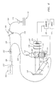
- FIG. 11 is a schematic diagram of an interferometer connected to an ultrasound console
- FIG. 12 is a schematic diagram of an AOM based interferometric system, as in the embodiment of FIG. 10 , coupled to an ultrasound console;
- FIG. 13 shows an interferometric system in accordance with the embodiment of FIG. 3 a contained within a housing for use with a interferometric catheter and an ultrasound console.
- FIG. 3 a is a schematic diagram of one embodiment of a diffraction grating based fiber optic interferometric system 100 .
- the system 100 comprises a light source 102 optically coupled to a fiber optic beam splitter 104 by an optical fiber 106 .
- the fiber optic beam splitter 104 is preferably approximately a 50/50 beam splitter. More preferably, the beam splitter 104 is a 50/50 beam splitter.
- An optical fiber 108 is optically coupled to the fiber optic beam splitter and to a focusing lens 110 .
- An optical fiber 111 is also optically coupled to the fiber optic beam splitter 104 such that light entering the beam splitter from the optical fiber 108 is coupled into the optical fiber 110 .
- the optical fiber 111 is also optically coupled to a first collimator 112 .
- Another optical fiber 114 is optically coupled to the first beam splitter 104 and to a second collimator 116 .
- the optical fibers 108 and 110 comprise first and second parts of a sample arm, respectively, of the interferometric system 100 .
- the optical fiber 114 comprises a reference arm of the system 100 .
- Light from the light source 102 passes through the fiber optic beam splitter 104 and is split into a sample light beam and a reference light beam, each having half of the energy of the initial light beam provided from the light source 102 to the fiber optic beam splitter 104 .
- the sample light beam is directed into the optical fiber 108 of the first part of the sample arm and the reference light beam is directed into the optical fiber 114 of the reference arm.
- the sample light beam is focused by the focusing lens 110 onto a sample of interest 119 , which may be tissue within a body cavity, for example.
- Light scattered by the sample is focused by the focusing lens 110 to form a second sample light beam and is coupled back into the optical fiber 108 of the sample arm. That light passes back through the first beam splitter 104 , where the light beam is split again. A light beam having half of the energy of the received light beam is coupled into the optical fiber 110 of the second part of the sample arm.
- the second collimator 116 collimates the reference light beam and directs the reference light beam onto a diffraction grating 118 at an angle ⁇ .
- the diffraction grating 118 introduces an optical path difference to the reference light beam and reflects the diffracted reference light beam onto a second, open space beam splitter 120 .
- the first collimator 112 also collimates the second sample light beam and directs it onto the second beam splitter 120 .
- the second beam splitter 120 combines the second sample light beam and the reference light beam and directs a portion of the combined light beam onto a photo detector 122 , through a conjugating lens 124 .
- the photo detector 112 is preferably a multi-element photo detector, such as a photo diode array. An array of avalanche mode photo diodes may be used, for example. A charge coupled-device (“CCD”) may be used, as well.
- the conjugating lens 124 projects the image of the combined beam on the plane of the second beam splitter onto the detector plane.
- the detector 122 is connected to a signal processor, such as a computer 126 , which processes the data received from the detectors to create an image on a display 128 , such as a monitor. The output of the detector 122 may be converted into a digital signal prior to being input to the computer 126 . The image may be printed as well.
- the open space beam splitter 120 directs less than half of the light energy in the reference beam and more than half of the energy in the second sample light beam into the combined beam directed toward the detector 122 .
- substantially more than half of the energy in the second sample light beam such as 75% or more, is directed into the combined beam and substantially less than half of the energy in the reference light beam, such as 25% or less, is directed into the combined light beam.
- at least about 90% or more of the energy of the sample light beam and about 10% or less of the energy of the reference light beam are directed into the combined beam.
- the second beam splitter may be a 10/90, 5/95, 2/98 or 1/99 beam splitter. In the embodiment of FIG.
- the reference light beam is transmitted through the second beam splitter 120 while the sample light beam is reflected by the second beam splitter 120 .
- the sample light beam may be transmitted through the second beam splitter 120 and the reference light beam may be reflected by the second beam splitter.
- the optical path lengths of the sample light beam (the initial sample light beam and the second light beam) and the reference light beam from the first beam splitter 104 to the second beam splitter 120 need to be equal to within the coherence length of the light source 102 .
- the refractive index of the optical fibers and the open space traversed by the light beams, as well as the refractive index of the sample material, need to be considered in determining appropriate path lengths.
- the interference pattern resulting from the combination of the sample and reference light beams contains both depth information and brightness information.
- the brightness information is provided by the light intensities of the interference pattern. Since the portion of the second sample light beam that is received in the sample arm from a certain depth from the sample interferes with a portion of the diffracted reference beam at a spatial position corresponding to the optical path difference for this position, the depth information is provided by the spatial position within the interference pattern.
- the photo detectors of the array 122 are arranged so that each photo detector element detects the light intensity of the interference pattern at a certain spatial position within the interference pattern, as is known in the art. Thus, the output of each photo detector element provides image brightness information for a certain image depth.
- the array 122 outputs the information along parallel channels (not shown), where each channel corresponds to the output of one of the photo detector elements.
- the outputs of the parallel channels of the photo array 122 are provided to the computer 126 for processing in accordance with known processing techniques to produce an image of the sample depth reflection along the sample light beam for display.
- the multi-element detector 122 is a photo diode array and a heterodyne detection technique is used.
- a modulator 117 such as a fiber stretcher or an acousto-optic modulator, is therefore provided along the optical fiber 114 .
- the modulator 117 may be provided along the optical fibers 108 or 111 to modulate the sample light beam, as well.
- the optical fiber 108 of the first part of the sample arm is preferably incorporated in a catheter adapted to be positioned in a body cavity or organ by standard catheter intervention procedures.
- the catheter may be inserted into a blood vessel or the heart by guiding the flexible catheter through various blood vessels along a circuitous path, starting, for example, by percutaneous introduction through an introducer sheath disposed in a perforation of the femoral artery.
- the catheter can be introduced directly into a body cavity or body tissue, such as an organ.
- the optical fiber may be coupled to a motor for causing rotation of the fiber within the catheter.
- Catheters and endoscopes for use in the optical imaging of blood vessels and other internal body cavities are known in the art and are described in U.S. Pat. Nos.
- a mirror or prism may be provided to reflect the sample light beam onto biological tissue parallel to the optical fiber and to reflect light received from the tissue into the optical fiber. By rotating the optical fiber, tissue along the circumference of the cavity may be examined.
- FIG. 3 b is a schematic diagram of an interferometric system 100 ′ that is similar to the system of FIG. 3 a , except that the second beam splitter 120 ′ is a 50/50 beam splitter.
- a neutral density filter or other such attenuator may be provided as needed to suppress the reference light beam to prevent saturation of the detector 124 .
- Components common to the embodiment of FIG. 3 a are commonly numbered.
- FIG. 4 is a schematic diagram of an interferometric system 150 with a similar arrangement to the system 100 of FIG. 3 a , except that the diffraction grating is a transparent diffraction grating 152 . Components common to the configuration of FIG. 3 a are commonly numbered in FIG. 4 .
- the second collimator 116 is arranged to direct the reference light beam on a rear side of the diffraction grating 152 at an angle ⁇ .
- the diffracted reference beam is directed onto the open space beam splitter 120 , for combination with the second sample light beam, as discussed above.
- the combined light beam is directed through the conjugating lens 124 and onto the multi-element detector 122 , also as described above.
- FIG. 5 is a schematic diagram of another embodiment of an interferometric system 200 , wherein more than half of the light energy is directed into the sample light beam and less than half of the light energy is directed into the reference light beam by use of a non 50/50 fiber optic beam splitter.
- substantially more than half of the light energy incident on the beam splitter such as 75% of the energy, is directed into the sample light beam and substantially less than half of the incident light energy, such as 25%, is directed into the reference light beam. More preferably, at least about 90% of the incident light energy is directed into the sample light beam and about 10% or less is directed into the reference light beam.
- the sample light beam is directed to and from the sample under examination through an optical circulator instead of a beam splitter, as in the embodiment of FIG. 3 a and in the prior art of FIGS. 1 and 2 . Therefore, the first beam splitter need not be approximately a 50/50 beam splitter.
- a light source 102 provides light to a 90/10 beam splitter 202 through an optical fiber 106 .
- the 90/10 fiber optic beam splitter 202 provides 90% of the energy of the light incident to the beam splitter 202 into the sample light beam and 10% of the energy of the light into the reference light beam.
- An optical circulator 204 is provided with three ports, Port 1 , Port 2 and Port 3 . Light entering the optical circulator 204 through Port 1 is directed out of the circulator through Port 2 . Light entering the optical circulator 204 through Port 2 is directed out of the circulator through Port 3 . An optical fiber 206 is optically coupled to the first beam splitter 202 to Port 1 of the optical circulator 204 to convey the sample light beam to the circulator.
- An optical fiber 208 is optically coupled to Port 2 of the optical circulator 204 and to a focusing lens 110 .
- An optical fiber 210 is optically coupled to Port 3 of the optical circulator 204 and to a first collimator 112 .
- the sample light beam is conveyed from the first beam splitter 202 to Port 1 of the optical circulator 204 through the optical fiber 206 .
- the sample light beam is directed to Port 2 of the optical circulator, where it exits the circulator and is conveyed to the focusing lens 110 by the optical fiber 208 .
- the focusing lens focuses the sample light beam onto the sample 119 .
- Light received from the sample is focused and coupled into the optical fiber 108 , forming a second sample light beam to be returned to Port 2 of the optical circulator.
- the second sample light beam is directed from Port 2 to Port 3 of the optical circulator, where it is conveyed by the optical fiber 204 to the first collimator 112 .
- An optical fiber 220 is also optically coupled to the beam splitter 202 and to a second collimator 116 , as in the embodiment of FIG. 3 a .
- a reference light beam having 10% of the energy of the light conveyed to the 90/10 beam splitter 202 from the light source 102 is directed into the optical fiber 220 .
- the second collimator 116 directs the reference light beam onto a reflective diffraction grating 118 .
- the diffraction grating 118 introduces an optical path difference to the reference light beam and reflects the diffracted reference light beam onto the open space beam splitter 120 .
- a transparent diffraction grating 152 could be used instead of the reflective diffraction grating 118 , as discussed above.
- the first collimator 112 also directs the second sample light beam onto the open space beam splitter 120 for combination with the reference light beam.
- the second beam splitter 120 is approximately a 50/50 beam splitter 222 .
- the second beam splitter 120 is a 50/50 beam splitter.
- Two combined sample/reference beams, each having half of the energy of the second sample light beam and half of the energy of the reference light beam, are formed.
- Two photo detectors 224 , 226 which are preferably multi-element photo detectors, are provided, one along the path of each combined light beam. Because two detectors are provided, the 50/50 beam splitter 222 does not cause a loss of energy and information in the second sample light beam.
- Respective conjugating lenses 228 , 230 are provided between each detector 224 , 226 and the second beam splitter 222 .
- the outputs of individual detectors in corresponding spatial positions in each array are combined by analog circuitry 227 .
- the output of the analog circuitry 227 which may be parallel or serial, is provided to a signal processor, such as the computer 126 , for processing into an image in a manner known in the art.
- the analog circuitry 227 may convert the signals output from the detectors 224 , 226 into digital signals, as well.
- Two detectors may be readily provided in the embodiment of FIG. 3 b , as well, in the same manner.
- the light energy is directed into the sample light beam and about 10% or less of the light energy is directed into the reference light beam by the first beam splitter 202 .
- the amount of energy provided to the sample and reference beams may be controlled by selection of the characteristics of the fiber optic beam splitter 202 so that only the necessary amount of light energy is provided to the reference light beam to sufficiently amplify the sample light beam for imaging without saturating the multi-element photo detectors 224 , 226 .
- the remainder of the energy is directed to the sample light beam.
- a 2/98, a 95/5 or a 1/99 or other such beam splitter may also be used, for example.
- the loss in the optical circulator is between about 0.5 decibels (“db”) to about 1.1 db each way.
- the two way loss in the optical circulator is therefore about 1.0 db to about 2.2 db (about 37%).
- the loss in a 50/50 beam splitter 222 is 50% each way or 75% if the sample beam travels through the 50/50 beam splitter twice.
- the detectors 224 , 226 may be tuned to detect light at the same wavelength band or at different wavelength bands. The ability to detect more than one wavelength band is useful for spectroscopy and for reducing aliasing in the image.
- the two combined sample/reference light beams in the embodiment of FIG. 5 may contain polarization related information. Birefringence measurements may be made by providing a polarization filter along each light beam, where each filter allows passage of light having a different polarization.
- polarization filters 240 , 242 are shown between each of the conjugating lenses 228 , 230 and the detectors 224 , 226 , respectively.
- the outputs of each detector 222 , 224 may be provided to the computer separately, for processing.
- Two images may be displayed. Differential measurements may be made by comparing the signals at each detector as a function of spatial position and relative intensity, as is also known in the art. Variations in intensity versus position are an indication of polarity sensitive areas of target tissue.
- the optical fiber used in this embodiment is preferably a polarization maintaining (high birefringence) optical fiber, as is known in the art.
- a polarization filter 243 shown in phantom, may also be provided between the light source 102 and the fiber optic beam splitter 202 instead of the polarization filters 240 , 242 , to polarize the light beam emitted by the light source to a desired polarization.
- the second beam splitter 222 may be a polarization beam splitter.
- a single detector as in the embodiments of FIGS. 3 and 4 , may also be used to detect a light beam of a particular polarization.
- Polarization filters may be provided in other interferometric systems where two combined beams are formed, as well.
- a 50/50 beam splitter may also be provided between the diffraction grating 32 and the detector 34 in the system of the '133 patent shown in FIG. 1 , to form two combined beams.
- a second detector, two polarization filters and two conjugating lenses may then be provided, as in FIG. 6 , to conduct birefrigence measures.
- a second light source 103 may be provided, as shown in FIG. 7 . Additional light sources may also be provided. Each light source may emit light at a different wavelength. For example, the first light source can emit light at 800 nanometers and the second light source can emit light at 1200 nanometers. The light from the second light source 103 may be coupled into the optical fiber 106 by a wavelength division multiplexor, for example. One of the detectors 224 , 226 may be tuned to detect light at a wavelength corresponding to the first light source 102 and the other detector may be tuned to detect light at a wavelength band corresponding to the second light source 103 .
- the individual photo detectors in each array can be tuned to detect light at different wavelength bands. Bandpass filtering, detector response and the fiber characteristics of each “detection channel” may be selected to optimize the use of specific wavelengths.
- the outputs of each detector 222 , 224 may be provided to the computer separately for processing. Two or more images may be displayed. The interference patterns at each wavelength band may be compared as a function of spatial position and intensity at each wavelength band. The difference in intensity at the same position in the interference patterns may indicate wavelength dependent attenuation or absorption of the sample.
- Fluorescence of tissue is known to be dependant upon tissue type and tissue constituents.
- One of the light sources in FIG. 7 may be in the blue or ultraviolet range, for example, to induce fluorescence in the tissue.
- One of the detectors 224 , 226 may be tuned to the ultraviolet, blue or other wavelength band at which the target tissue is expected to fluoresce to detect the intensity of the emitted fluorescent light.
- neither the first fiber optic beam splitter nor the second open space beam splitter is a 50/50 beam splitter.
- the first beam splitter 282 is a 95/5 beam splitter, for example, that directs 95% of the light energy provided to the beam splitter into the sample light beam and 10% into the reference light beam.
- the second open space beam splitter 284 is a 10/90 beam splitter, for example, directing 90% of the light energy in the second sample light beam and 10% or less of the light energy in the reference light beam toward a single detector 286 in the combined beam. Varying the characteristics of both beam splitters 282 , 284 provides additional flexibility in optimizing the energy distribution between the sample and reference light beams. Components of the system 280 common to the embodiments of FIGS. 5 and 3 a are commonly numbered.
- the sample under examination may be replaced by a mirror.
- the Table below shows the percentage of the light source energy in the sample and reference arms at the sample, at the diffraction grating and at the detector in the prior art interferometer of FIG. 1 and in the example interferometers of FIGS. 3 a , 4 and 5 , if the sample light beam is reflected by a mirror (suffers no loss due to interaction with the sample).
- Sample Diffraction Grating Detector/Detectors FIG. Sample Arm Sample Arm Reference Arm Sample Arm Reference Arm FIG. 1 50 25 50 12.5 25 FIG. 3a 50 NA 50 22.5 2.5 FIG. 4 50 NA 50 22.5 2.5 FIG. 5 90 NA 10 56.7 5
- the light energy in the reference light beam incident on the detector is 25% of the light energy from the source and is higher than the sample light energy.
- the reference beam has to be suppressed.
- the light source energy in the sample arm is reduced by 75% by two passes through the 50/50 beam splitter and then by 10% by the 10/90 beam splitter.
- the light source energy is reduced by 50% by the first beam splitter, 50% by the diffraction grating and 90% by the second beam splitter.
- the light source energy is reduced by 10% by the 90/10 beam splitter and by 37% by two passes through the optical circulator.
- the loss caused by the 50/50 beam splitter does not reduce the total energy of the sample light beam because the total energy of the light incident on both detectors by the sample light beam is the same as the energy of the sample light beam incident on the beam splitter.
- the light is reduced to 10% of the light energy from the source by the 10/90 beam splitter and then by 50% by the diffraction grating.
- the proportion of the initial light energy in the reference light beam incident on the detector is much lower than in the prior art and the proportion of the light energy in the sample light beam is higher. Saturation of the detector or detectors may be readily avoided by suitable selection of the characteristics of the beam splitters.
- a neutral density filter may be provided along the reference arm for more precise control over the energy of the reference light beam, if necessary. Since more of the light energy from the source may be allocated to the sample light beam, where it is most needed, less energy is wasted in the system.
- FIG. 9 is an enlarged view of the reference light beam R emitted by the collimator 116 being diffracted by the diffraction grating 118 , showing the maximum optical path difference 6 across the diffracted reference light beam Rd for the embodiment of FIG. 3 a .
- the second sample light beam S received from the sample is shown being emitted by the collimator 112 .
- the second beam splitter 120 is also shown.
- the optical path difference ⁇ varies gradually across the diffracted reference light beam Rd such that the difference at one side of the beam cross-section “a” is about zero and the difference at the opposite side of the beam “b” is the maximum difference ⁇ .
- the maximum optical path difference ⁇ is typically chosen to enable measurement of the light scattered from the desired depth.
- the optical path difference ⁇ corresponds to the depth of the image in the second sample light beam S, corrected by the refractive index of the media in which the depth is measured.
- the angle of incidence ⁇ of the reference light beam on the diffraction grating is a function of the diffraction grating parameter p (distance between adjacent grooves) and the light wavelength ⁇ .
- the width Wref of the reference light beam R is less than the width Wd of the diffracted reference light beam Rd.
- the width Wd of the diffracted reference light beam is the same as the width Ws of the second sample light beam S.
- the combined light beam (not shown) has the same width.
- the width of the detector array or arrays should the same or slightly greater than the width of the combined light beam.
- the first collimator 112 that collimates the second sample light beam S received from the sample, has the same dimensions as that of the detection array.
- the width of the combined light beam is also Wd.
- the photo detector array would then also have a width of at least 11.45 mm.
- the light source 102 is a low coherence, broadband light source, such as a super luminescent diode.
- the coherence length of the light source may be from about 15 to about 30 microns, for example.
- the wavelength may be between about 800 to about 1500 nanometers, for use with biological tissue.
- the light source should emit light at a power of at least about 10 milliwatts for depth measurements of about 1 millimeter.
- the light source should emit light at a power of at least about 50 milliwatts for depth measurements of 2-3 millimeters.
- Superluminescent diodes for use in the embodiments may be obtained from Super Lume Diodes, Ltd. Moscow, Russia, or Hamamatsu Photonics K.K., Solid State Division, Hamamatsu City, Japan, (“Hamamatsu”) for example.
- the detector is preferably a multi-element photo detector, such as a photo diode array.
- An avalanche mode photo diode array may be used, for example
- the photodiode array preferably has at least 256 diodes. An array of 512 photo diodes or more is more preferred.
- Photo diode arrays may be obtained from Sensors Unlimited, Inc., Princeton, N.J. and Hamamatsu, for example.
- a charge-coupled device (“CCD”) may also be used.
- Appropriate optical fibers and fiber optic beam splitters of desired characteristics are readily commercially available. They may be obtained from Coming Incorporated, Corning, N.Y., for example. Open space beam splitters of desired characteristics are also readily commercially available. They may be obtained from Edmunds Scientific, Tonawanda, N.Y., for example. The conjugating lenses and focussing lens may also be obtained from Edmunds Scientific, for example.
- FIG. 10 is yet another embodiment of an interferometric system 300 , wherein an acousto-optic modulator (“AOM”) 302 acts as both a transparent diffraction grating to introduce an optical path difference to the reference light beam and as a modulator to introduce a frequency shift. Otherwise, the system is the same as the embodiment of FIG. 3 a .
- AOM acousto-optic modulator
- One AOM may be used for shallow depths of a few hundred microns, for example.
- Two modulators may be used for greater depths of 500 to 1,000 microns, for example.
- One AOM may also be used along with a transparent diffraction grating, as shown in U.S. Pat. No. 6,114,645, which is incorporated by reference herein.
- While one AOM may introduce a frequency of modulation higher than that desirable in an OCT system, two or more AOM's in series, each driven at different frequencies, may be used to achieve the desired frequency.
- the AOM 302 may be driven by a programmable signal generator, as is known in the art.
- pulsed imaging may also be implemented in any of the embodiments discussed above. Pulsed imaging allows for the use of higher peak power and lower average power (lower duty cycle), enabling increased penetration through attenuative structures while maintaining low average light energy for safe operation.
- a laser diode may be used in a pulsed mode as the light source in any of the embodiments. The laser diode may be smaller and less expensive than the superluminescent diode discussed above for continuous operation, because a small laser diode may produce a sufficient peak output at a wider bandwidth in a pulse mode without being destroyed.
- FIG. 11 is a schematic diagram of an imaging system 390 comprising an interferometer 391 including a photo detector array 392 with a plurality of parallel outputs 394 connected to an ultrasound console 396 through a parallel to serial converter 398 .
- An ultrasound device 399 is also shown, with an output 399 a .
- the output 399 a of the ultrasound device 399 may also be connected to the ultrasound console, in the same or a different input than the interferometer 391 .
- a doctor or technician may thereby use either the interferometer 391 for optical imaging or the ultrasound device 399 for ultrasound imaging, with the same ultrasound console.
- the parallel to serial converter 398 is discussed further below. First, ultrasound imaging is briefly discussed.
- Ultrasound medical imaging is a commonly used procedure to produce images of body cavities such as blood vessels and surrounding tissue.
- an Intravascular Ultrasound (“IVUS”) catheter is typically inserted into the blood vessel in a known manner.
- An example of an IVUS catheter may be found in U.S. Pat. No. 5,715,825, entitled Acoustic Imaging Catheter and the Like, incorporated by reference herein.
- an ultrasound transducer In ultrasound imaging, an ultrasound transducer is supported at the distal end of an IVUS catheter, for example.
- the transducer emits ultrasound waves in the blood vessel or other such cavity when excited by a pulse. A portion of the emitted ultrasound waves is reflected back to the ultrasound transducer by tissue boundaries. The reflected ultrasound waves induce an echo signal at the ultrasound transducer.
- the echo signal is transmitted from the ultrasound transducer to an ultrasound console, which typically includes an ultrasound image processor, such as a computer, a microprocessor or a microcontroller, and a display.
- the display may comprise a monitor and/or a printer.
- the ultrasound console uses the received echo signal to image the cavity.
- An ultrasound system including an ultrasound image processor and display is available from Boston Scientific Corporation, Natick, Mass.
- the echo signal is a serial amplitude modulated signal in which the amplitude of the signal varies with time.
- a typical echo signal has a time length of 8 ⁇ s, which corresponds to an image depth of approximately 6 millimeters from the ultrasound transducer.
- the echo signal carries both image brightness information and image depth information, where depth may be taken with respect to the ultrasound transducer.
- the image brightness information is provided by the amplitude of the echo signal.
- the image depth information is provided by the time position within the echo signal. An earlier time position in the echo signal corresponds to a lower image depth than a later time position in the echo signal.
- the array captures image brightness information at multiple image depths in one instance. Since the detected spatial information may be read and stored, the parallel channel outputs of the photo detector array of the interferometric system may be processed into a serial analog or serial digital signal by a parallel to serial converter. The resulting serial signal carries image brightness information and image depth information in a similar manner as a typical echo signal. The time length and/or frequency of the serial signal may be adjusted to better match the time length and/or frequency of a typical echo signal that the ultrasound console is configured to receive by synchronizing the signal to the sweep speed of the ultrasound device (speed of rotation of the transducer) and to the propagation velocity of sound.
- the same ultrasound console may thereby be used to process both ultrasound based images derived from data received from an ultrasound catheter and optical interferometric based images derived from data received from an interferometric catheter, thereby reducing the cost of having both ultrasound imaging and optical imaging capabilities.
- FIG. 12 shows an AOM based interferometric system 400 , as in the embodiment of FIG. 10 , wherein the first, fiber optic beam splitter 202 is a 90/10 beam splitter and the second, open space beam splitter 222 is a 50/50 beam splitter.
- Two photo detector arrays 224 , 226 are provided, as in the embodiment of FIG. 5 .
- the outputs of corresponding detectors in each of the parallel outputs from the photo detector arrays 224 , 226 of the interferometric system 400 are combined by analog circuitry 227 , as discussed.
- the parallel outputs of the analog circuitry 227 are input to a parallel to serial converter 398 that converts the parallel outputs into a serial amplitude modulated signal that can be processed by an ultrasound console. If only one detector is provided, as in the embodiment of FIG. 3 a , for example, the analog circuitry 227 is not needed and the parallel outputs of the photo detector array 122 could be provided directly to the parallel to serial converter 398 .
- a computer 404 may optionally be provided to process the serial signal output by the parallel to serial converter.
- the serial signal is then provided to the IVUS console 396 through an input 405 for processing into an image for display.
- the IVUS console comprises a signal processor, such as a computer, a microprocessor or a microcontroller, and a display to display generated images, as is known in the art.
- the interferometer may be selectively connected to the input 405 when optical imaging is desired.
- An ultrasound catheter 399 is also shown in FIG. 12 , with an output 399 a .
- the output 399 a may be connected to the input 405 or a separate input 417 of the IVUS console 396 when ultrasound imaging is desired.
- interferometric systems as well as other interferometric systems, could be used with the IVUS console, as well.
- the optical fiber 208 of the sample arm is shown coupled to an optical fiber 407 within a catheter 408 through a rotary connector 410 .
- a mirror or prism 412 is shown for reflecting the sample light beam out of the catheter to tissue in a body cavity, as described above.
- the rotary connector 410 is driven by a motor, as is known in the art.
- the parallel to serial converter may be one of the electronic interfaces described in U.S. patent application Ser. No. 09/909,357 (“the '357 application”), entitled “Electronics Interface for an Ultrasound Console”, filed on Jul. 18, 2001, assigned to the assignee of the invention and incorporated by reference herein.
- the ultrasound console 396 may be configured to receive either an analog or a digital input.
- the electronics interface comprises a plurality of channel processors, each coupled to one of the parallel channel outputs of the photo array.
- Each channel processor comprises an analog processor, an A/D converter, a First-In-First-Out (“FIFO”) memory buffer and a data bus coupled to the FIFO memory buffer of each one of the channel processors.
- a single FIFO memory buffer is coupled to the data bus and a D/A converter is coupled to the output of the single FIFO memory buffer. The output of the D/A converter is coupled to the input of the ultrasound console.
- a controller coupled to an ultrasound motor encoder synchronizes the operation of the electronics interface with the ultrasound console, based on the rotation of the motor rotating the rotary connector 410 coupled to the optical fiber 407 within the catheter 408 .
- the operation of the interface is described in more detail in the '357 application.
- the serial digital data sequence from the single FIFO memory is provided to the input of the console through control logic that controls the transfer of the digital data sequence, as is also described in the '357 application.
- the photo detector array may be a multiplexed photo detector array. Electrical interfaces for single and double channel multiplexed photo detector arrays are also described in the '357 application.
- FIG. 13 shows a housing 420 containing an interferometer in accordance with the embodiment of FIG. 3 a of the present invention for use with an interferometric catheter 408 and an IVUS console 396 .
- Components common to the other embodiments are commonly numbered.
- the light source 102 , the fiber optic beam splitter 104 , the optical fibers 106 , 108 , 110 and 114 , the diffraction grating 118 , the collimators 112 , 116 , the open space beam splitter 120 , the conjugating lens 124 and the multi-element detector 122 are shown.
- the rotary coupler 410 of FIG. 11 is also shown.
- a motor 422 is provided in the housing 420 to rotate the rotary coupler 410 and the optical fiber 407 within the catheter 408 .
- a motor controller 424 controls the operation of the motor 422 .
- a power supply 426 is shown, as well.
- Data acquisition and processing boards 428 are provided, electrically connected to a cable 430 for connection to the IVUS console 396 of FIG. 11 .
- the parallel to serial converter 398 in FIG. 12 may be included on the processing boards.
- a port 428 of the housing and a catheter adapter 430 for connection to the port are shown as well.
- any of the embodiments of the interferometric systems described herein, as well as other fiber optic and non fiber optic OCT systems using a multi-element photo detector, may be used in the imaging system 390 .
- the systems of U.S. Pat. No. 5,943,133 and “Nonmechanical grating-generated scanning coherence microscopy”, Optics Letters, Vol. 23, No. 23, Dec. 1, 1998, discussed above and incorporated by reference herein, in their entirety, may also be used.
- an oscillating mirror or other such reflector may be used to scan a sample depth.
- interferometers such as those described in U.S. Pat. Nos. 6,134,003, 6,111,645, 5,459,570, 5,321,501 and International Publication No. WO 98/38907 published on Sep. 11, 1998, for example, which are also incorporated by reference herein, may also be used in the imaging system with an interface disclosed in the '903 application or other such interfaces.
- the sample arm may be incorporated in an endoscope for insertion into the gastrointestinal tract, for example.
- the sample arm may also have a probe at its end for examining external biological tissue, such as the eye, or other types of samples, such as semiconductors.
- a non fiber optic interferometer may be used in accordance with the invention.
- one collimator is preferably provided between the light source and the first beam splitter.
- a single element photo detector may also be used, in which case the width of the combined light beam could be moved across the detector or the detector could be moved across the width of the combined light beam.
- focusing lens Use of a focusing lens, first and second collimators and one or two conjugating lenses are also preferred, but not required.
Abstract
Description
| Percentage of light source energy incident on: | ||
| Sample | Diffraction Grating | Detector/Detectors |
| FIG. | Sample Arm | Sample Arm | Reference Arm | Sample Arm | Reference Arm |
|
|
50 | 25 | 50 | 12.5 | 25 |
|
|
50 | |
50 | 22.5 | 2.5 |
|
|
50 | |
50 | 22.5 | 2.5 |
|
|
90 | |
10 | 56.7 | 5 |
δ=Wd×Sin α. (1)
Δ=δ/2η. (2)
Sin α=λ/p. (3)
Wref=Ws/Cos α. (4)
Claims (76)
Priority Applications (4)
| Application Number | Priority Date | Filing Date | Title |
|---|---|---|---|
| US10/017,534 US7006231B2 (en) | 2001-10-18 | 2001-10-18 | Diffraction grating based interferometric systems and methods |
| US11/166,522 US7130054B2 (en) | 2001-10-18 | 2005-06-24 | Diffraction grating based interferometric systems and methods |
| US11/531,211 US7426037B2 (en) | 2001-10-18 | 2006-09-12 | Diffraction grating based interferometric systems and methods |
| US12/210,967 US7728983B2 (en) | 2001-10-18 | 2008-09-15 | Diffraction grating based interferometric systems and methods |
Applications Claiming Priority (1)
| Application Number | Priority Date | Filing Date | Title |
|---|---|---|---|
| US10/017,534 US7006231B2 (en) | 2001-10-18 | 2001-10-18 | Diffraction grating based interferometric systems and methods |
Related Child Applications (1)
| Application Number | Title | Priority Date | Filing Date |
|---|---|---|---|
| US11/166,522 Continuation US7130054B2 (en) | 2001-10-18 | 2005-06-24 | Diffraction grating based interferometric systems and methods |
Publications (2)
| Publication Number | Publication Date |
|---|---|
| US20030081220A1 US20030081220A1 (en) | 2003-05-01 |
| US7006231B2 true US7006231B2 (en) | 2006-02-28 |
Family
ID=21783134
Family Applications (4)
| Application Number | Title | Priority Date | Filing Date |
|---|---|---|---|
| US10/017,534 Expired - Lifetime US7006231B2 (en) | 2001-10-18 | 2001-10-18 | Diffraction grating based interferometric systems and methods |
| US11/166,522 Expired - Lifetime US7130054B2 (en) | 2001-10-18 | 2005-06-24 | Diffraction grating based interferometric systems and methods |
| US11/531,211 Expired - Lifetime US7426037B2 (en) | 2001-10-18 | 2006-09-12 | Diffraction grating based interferometric systems and methods |
| US12/210,967 Expired - Fee Related US7728983B2 (en) | 2001-10-18 | 2008-09-15 | Diffraction grating based interferometric systems and methods |
Family Applications After (3)
| Application Number | Title | Priority Date | Filing Date |
|---|---|---|---|
| US11/166,522 Expired - Lifetime US7130054B2 (en) | 2001-10-18 | 2005-06-24 | Diffraction grating based interferometric systems and methods |
| US11/531,211 Expired - Lifetime US7426037B2 (en) | 2001-10-18 | 2006-09-12 | Diffraction grating based interferometric systems and methods |
| US12/210,967 Expired - Fee Related US7728983B2 (en) | 2001-10-18 | 2008-09-15 | Diffraction grating based interferometric systems and methods |
Country Status (1)
| Country | Link |
|---|---|
| US (4) | US7006231B2 (en) |
Cited By (157)
| Publication number | Priority date | Publication date | Assignee | Title |
|---|---|---|---|---|
| US20020198457A1 (en) * | 2001-04-30 | 2002-12-26 | Tearney Guillermo J. | Method and apparatus for improving image clarity and sensitivity in optical coherence tomography using dynamic feedback to control focal properties and coherence gating |
| US20030028100A1 (en) * | 2001-05-01 | 2003-02-06 | Tearney Guillermo J. | Method and apparatus for determination of atherosclerotic plaque type by measurement of tissue optical properties |
| US20050004453A1 (en) * | 2003-01-24 | 2005-01-06 | Tearney Guillermo J. | System and method for identifying tissue using low-coherence interferometry |
| US20050018201A1 (en) * | 2002-01-24 | 2005-01-27 | De Boer Johannes F | Apparatus and method for ranging and noise reduction of low coherence interferometry lci and optical coherence tomography oct signals by parallel detection of spectral bands |
| US20050018200A1 (en) * | 2002-01-11 | 2005-01-27 | Guillermo Tearney J. | Apparatus for low coherence ranging |
| US20050035295A1 (en) * | 2003-06-06 | 2005-02-17 | Brett Bouma | Process and apparatus for a wavelength tuning source |
| US20050128488A1 (en) * | 2003-11-28 | 2005-06-16 | Dvir Yelin | Method and apparatus for three-dimensional spectrally encoded imaging |
| US20050185271A1 (en) * | 2004-02-25 | 2005-08-25 | Delta Electronics, Inc. | Fabrication method for rear-projection screen |
| US20060013544A1 (en) * | 2004-07-02 | 2006-01-19 | Bouma Brett E | Imaging system and related techniques |
| US20060039004A1 (en) * | 2004-08-06 | 2006-02-23 | The General Hospital Corporation | Process, system and software arrangement for determining at least one location in a sample using an optical coherence tomography |
| US20060058622A1 (en) * | 2004-08-24 | 2006-03-16 | The General Hospital Corporation | Method and apparatus for imaging of vessel segments |
| US20060055936A1 (en) * | 2004-09-10 | 2006-03-16 | The General Hospital Corporation | System and method for optical coherence imaging |
| US20060058592A1 (en) * | 2004-08-24 | 2006-03-16 | The General Hospital Corporation | Process, system and software arrangement for measuring a mechanical strain and elastic properties of a sample |
| US20060067620A1 (en) * | 2004-09-29 | 2006-03-30 | The General Hospital Corporation | System and method for optical coherence imaging |
| US20060093276A1 (en) * | 2004-11-02 | 2006-05-04 | The General Hospital Corporation | Fiber-optic rotational device, optical system and method for imaging a sample |
| US20060109478A1 (en) * | 2004-11-24 | 2006-05-25 | The General Hospital Corporation | Devices and arrangements for performing coherence range imaging using a common path interferometer |
| US20060114473A1 (en) * | 2004-11-29 | 2006-06-01 | The General Hospital Corporation | Arrangements, devices, endoscopes, catheters and methods for performing optical imaging by simultaneously illuminating and detecting multiple points on a sample |
| US20060227333A1 (en) * | 2003-03-31 | 2006-10-12 | Tearney Guillermo J | Speckle reduction in optical coherence tomography by path length encoded angular compounding |
| US20060244973A1 (en) * | 2003-10-27 | 2006-11-02 | Seok-Hyun Yun | Method and apparatus for performing optical imaging using frequency-domain interferometry |
| US20060270929A1 (en) * | 2005-05-31 | 2006-11-30 | The General Hospital Corporation | System, method and arrangement which can use spectral encoding heterodyne interferometry techniques for imaging |
| US20070009935A1 (en) * | 2005-05-13 | 2007-01-11 | The General Hospital Corporation | Arrangements, systems and methods capable of providing spectral-domain optical coherence reflectometry for a sensitive detection of chemical and biological sample |
| US20070012886A1 (en) * | 2005-04-28 | 2007-01-18 | The General Hospital Corporation | Systems. processes and software arrangements for evaluating information associated with an anatomical structure by an optical coherence ranging technique |
| US20070024869A1 (en) * | 2001-10-18 | 2007-02-01 | Isaac Ostrovsky | Diffraction Grating Based Interferometric Systems And Methods |
| US20070035743A1 (en) * | 2005-08-09 | 2007-02-15 | The General Hospital Corporation | Apparatus, methods and storage medium for performing polarization-based quadrature demodulation in optical coherence tomography |
| US20070049833A1 (en) * | 2005-08-16 | 2007-03-01 | The General Hospital Corporation | Arrangements and methods for imaging in vessels |
| US20070073162A1 (en) * | 2000-10-30 | 2007-03-29 | The General Hospital Corporation | Methods and systems for tissue analysis |
| US20070081236A1 (en) * | 2005-09-29 | 2007-04-12 | The General Hospital Corporation | Method and apparatus for optical imaging via spectral encoding |
| US20070087445A1 (en) * | 2005-10-14 | 2007-04-19 | The General Hospital Corporation | Arrangements and methods for facilitating photoluminescence imaging |
| US20070171430A1 (en) * | 2006-01-20 | 2007-07-26 | The General Hospital Corporation | Systems and methods for providing mirror tunnel micropscopy |
| US20070171433A1 (en) * | 2006-01-20 | 2007-07-26 | The General Hospital Corporation | Systems and processes for providing endogenous molecular imaging with mid-infrared light |
| US20070179487A1 (en) * | 2006-02-01 | 2007-08-02 | The General Hospital Corporation | Apparatus for applying a plurality of electro-magnetic radiations to a sample |
| US20070188855A1 (en) * | 2006-01-19 | 2007-08-16 | The General Hospital Corporation | Apparatus for obtaining information for a structure using spectrally-encoded endoscopy teachniques and methods for producing one or more optical arrangements |
| US20070201033A1 (en) * | 2006-02-24 | 2007-08-30 | The General Hospital Corporation | Methods and systems for performing angle-resolved fourier-domain optical coherence tomography |
| US20070208400A1 (en) * | 2006-03-01 | 2007-09-06 | The General Hospital Corporation | System and method for providing cell specific laser therapy of atherosclerotic plaques by targeting light absorbers in macrophages |
| US20070223006A1 (en) * | 2006-01-19 | 2007-09-27 | The General Hospital Corporation | Systems and methods for performing rapid fluorescence lifetime, excitation and emission spectral measurements |
| US20070239033A1 (en) * | 2006-03-17 | 2007-10-11 | The General Hospital Corporation | Arrangement, method and computer-accessible medium for identifying characteristics of at least a portion of a blood vessel contained within a tissue using spectral domain low coherence interferometry |
| US20070236700A1 (en) * | 2006-04-05 | 2007-10-11 | The General Hospital Corporation | Methods, arrangements and systems for polarization-sensitive optical frequency domain imaging of a sample |
| US20070263227A1 (en) * | 2006-05-12 | 2007-11-15 | The General Hospital Corporation | Processes, arrangements and systems for providing a fiber layer thickness map based on optical coherence tomography images |
| US20070263208A1 (en) * | 2006-01-10 | 2007-11-15 | The General Hospital Corporation | Systems and methods for generating data based on one or more spectrally-encoded endoscopy techniques |
| US20070276269A1 (en) * | 2006-05-10 | 2007-11-29 | The General Hospital Corporation | Process, arrangements and systems for providing frequency domain imaging of a sample |
| US20070274650A1 (en) * | 2006-02-01 | 2007-11-29 | The General Hospital Corporation | Apparatus for controlling at least one of at least two sections of at least one fiber |
| US20070282403A1 (en) * | 2006-02-01 | 2007-12-06 | The General Hospital Corporation | Methods and systems for providing electromagnetic radiation to at least one portion of a sample using conformal laser therapy procedures |
| US20080002211A1 (en) * | 2006-01-20 | 2008-01-03 | The General Hospital Corporation | System, arrangement and process for providing speckle reductions using a wave front modulation for optical coherence tomography |
| US20080007734A1 (en) * | 2004-10-29 | 2008-01-10 | The General Hospital Corporation | System and method for providing Jones matrix-based analysis to determine non-depolarizing polarization parameters using polarization-sensitive optical coherence tomography |
| US20080021275A1 (en) * | 2006-01-19 | 2008-01-24 | The General Hospital Corporation | Methods and systems for optical imaging or epithelial luminal organs by beam scanning thereof |
| US20080049232A1 (en) * | 2006-08-25 | 2008-02-28 | The General Hospital Coporation | Apparatus and methods for enhancing optical coherence tomography imaging using volumetric filtering techniques |
| US20080094637A1 (en) * | 2003-01-24 | 2008-04-24 | The General Hospital Corporation | Apparatus and method for ranging and noise reduction of low coherence interferometry lci and optical coherence tomography oct signals by parallel detection of spectral bands |
| US20080097225A1 (en) * | 2006-10-19 | 2008-04-24 | The General Hospital Corporation | Apparatus and method for obtaining and providing imaging information associated with at least one portion of a sample, and effecting such portion(s) |
| US20080175280A1 (en) * | 2007-01-19 | 2008-07-24 | The General Hospital Corporation | Wavelength tuning source based on a rotatable reflector |
| US20080206804A1 (en) * | 2007-01-19 | 2008-08-28 | The General Hospital Corporation | Arrangements and methods for multidimensional multiplexed luminescence imaging and diagnosis |
| US20080232410A1 (en) * | 2007-03-23 | 2008-09-25 | The General Hospital Corporation | Methods, arrangements and apparatus for utilizing a wavelength-swept laser using angular scanning and dispersion procedures |
| US20080234586A1 (en) * | 2007-03-19 | 2008-09-25 | The General Hospital Corporation | System and method for providing noninvasive diagnosis of compartment syndrome using exemplary laser speckle imaging procedure |
| US20080234567A1 (en) * | 2007-03-19 | 2008-09-25 | The General Hospital Corporation | Apparatus and method for providing a noninvasive diagnosis of internal bleeding |
| US20080262359A1 (en) * | 2007-03-30 | 2008-10-23 | The General Hospital Corporation | System and method providing intracoronary laser speckle imaging for the detection of vulnerable plaque |
| US20080275304A1 (en) * | 2003-05-22 | 2008-11-06 | Barbato Louis J | Systems And Methods For Dynamic Optical Imaging |
| US20080287808A1 (en) * | 2006-09-12 | 2008-11-20 | The General Hospital Corporation | Apparatus, probe and method for providing depth assessment in an anatomical structure |
| US20090027688A1 (en) * | 2003-12-22 | 2009-01-29 | Bossa Nova Technologies, Llc | Multi-channel laser interferometric method and apparatus for detection of ultrasonic motion from a surface |
| US20090036782A1 (en) * | 2007-07-31 | 2009-02-05 | The General Hospital Corporation | Systems and methods for providing beam scan patterns for high speed doppler optical frequency domain imaging |
| US20090059360A1 (en) * | 2007-08-31 | 2009-03-05 | The General Hospital Corporation | System and method for self-interference fluorescence microscopy, and computer-accessible medium associated therewith |
| US20090073439A1 (en) * | 2007-09-15 | 2009-03-19 | The General Hospital Corporation | Apparatus, computer-accessible medium and method for measuring chemical and/or molecular compositions of coronary atherosclerotic plaques in anatomical structures |
| US20090122302A1 (en) * | 2007-10-30 | 2009-05-14 | The General Hospital Corporation | System and method for cladding mode detection |
| US20090131801A1 (en) * | 2007-10-12 | 2009-05-21 | The General Hospital Corporation | Systems and processes for optical imaging of luminal anatomic structures |
| US20090143686A1 (en) * | 2007-11-20 | 2009-06-04 | Terumo Kabushiki Kaisha | Optical coherent tomography diagnostic apparatus |
| US20090192358A1 (en) * | 2008-01-28 | 2009-07-30 | The General Hospital Corporation | Systems, processes and computer-accessible medium for providing hybrid flourescence and optical coherence tomography imaging |
| US20090196477A1 (en) * | 2004-05-29 | 2009-08-06 | The General Hospital Corporation | Process, System And Software Arrangement For A Chromatic Dispersion Compensation Using Reflective Layers In Optical Coherence Tomography (OCT) Imaging |
| US20090225324A1 (en) * | 2008-01-17 | 2009-09-10 | The General Hospital Corporation | Apparatus for providing endoscopic high-speed optical coherence tomography |
| AU2003210669B2 (en) * | 2002-01-24 | 2009-10-29 | The General Hospital Corporation | Apparatus and method for rangings and noise reduction of low coherence interferometry LCI and optical coherence tomography (OCT) signals by parallel detection of spectral bands |
| US20090323056A1 (en) * | 2007-05-04 | 2009-12-31 | The General Hospital Corporation | Methods, arrangements and systems for obtaining information associated with a sample using optical microscopy |
| US20100110414A1 (en) * | 2008-05-07 | 2010-05-06 | The General Hospital Corporation | System, method and computer-accessible medium for tracking vessel motion during three-dimensional coronary artery microscopy |
| US20100149519A1 (en) * | 2008-06-12 | 2010-06-17 | Mehrdad Toofan | Polarization contrast imager (pci) |
| US20100165335A1 (en) * | 2006-08-01 | 2010-07-01 | The General Hospital Corporation | Systems and methods for receiving and/or analyzing information associated with electro-magnetic radiation |
| US20100207037A1 (en) * | 2009-01-26 | 2010-08-19 | The General Hospital Corporation | System, method and computer-accessible medium for providing wide-field superresolution microscopy |
| WO2010111795A1 (en) | 2009-04-03 | 2010-10-07 | Exalos Ag | Light source, and optical coherence tomography module |
| US7911621B2 (en) | 2007-01-19 | 2011-03-22 | The General Hospital Corporation | Apparatus and method for controlling ranging depth in optical frequency domain imaging |
| US20110137178A1 (en) * | 2009-10-06 | 2011-06-09 | The General Hospital Corporation | Devices and methods for imaging particular cells including eosinophils |
| US20110201924A1 (en) * | 2002-04-30 | 2011-08-18 | The General Hospital Corporation | Method and Apparatus for Improving Image Clarity and Sensitivity in Optical Tomography Using Dynamic Feedback to Control Focal Properties and Coherence Gating |
| US20110218403A1 (en) * | 2010-03-05 | 2011-09-08 | The General Hospital Corporation | Systems, methods and computer-accessible medium which provide microscopic images of at least one anatomical structure at a particular resolution |
| US20110224541A1 (en) * | 2009-12-08 | 2011-09-15 | The General Hospital Corporation | Methods and arrangements for analysis, diagnosis, and treatment monitoring of vocal folds by optical coherence tomography |
| US20110226940A1 (en) * | 2008-06-20 | 2011-09-22 | The General Hospital Corporation | Fused fiber optic coupler arrangement and method for use thereof |
| US20110237892A1 (en) * | 2008-07-14 | 2011-09-29 | The General Hospital Corporation | Apparatus and methods for color endoscopy |
| US8045177B2 (en) | 2007-04-17 | 2011-10-25 | The General Hospital Corporation | Apparatus and methods for measuring vibrations using spectrally-encoded endoscopy |
| US8721077B2 (en) | 2011-04-29 | 2014-05-13 | The General Hospital Corporation | Systems, methods and computer-readable medium for determining depth-resolved physical and/or optical properties of scattering media by analyzing measured data over a range of depths |
| US8854627B2 (en) | 2001-07-16 | 2014-10-07 | Boston Scientific Scimed, Inc. | Electronically scanned optical coherence tomography with frequency modulated signals |
| US8937724B2 (en) | 2008-12-10 | 2015-01-20 | The General Hospital Corporation | Systems and methods for extending imaging depth range of optical coherence tomography through optical sub-sampling |
| US9069130B2 (en) | 2010-05-03 | 2015-06-30 | The General Hospital Corporation | Apparatus, method and system for generating optical radiation from biological gain media |
| US9178330B2 (en) | 2009-02-04 | 2015-11-03 | The General Hospital Corporation | Apparatus and method for utilization of a high-speed optical wavelength tuning source |
| US9286673B2 (en) | 2012-10-05 | 2016-03-15 | Volcano Corporation | Systems for correcting distortions in a medical image and methods of use thereof |
| US9292918B2 (en) | 2012-10-05 | 2016-03-22 | Volcano Corporation | Methods and systems for transforming luminal images |
| US9295391B1 (en) | 2000-11-10 | 2016-03-29 | The General Hospital Corporation | Spectrally encoded miniature endoscopic imaging probe |
| US9301687B2 (en) | 2013-03-13 | 2016-04-05 | Volcano Corporation | System and method for OCT depth calibration |
| US9307926B2 (en) | 2012-10-05 | 2016-04-12 | Volcano Corporation | Automatic stent detection |
| US9324141B2 (en) | 2012-10-05 | 2016-04-26 | Volcano Corporation | Removal of A-scan streaking artifact |
| US9330092B2 (en) | 2011-07-19 | 2016-05-03 | The General Hospital Corporation | Systems, methods, apparatus and computer-accessible-medium for providing polarization-mode dispersion compensation in optical coherence tomography |
| US9341783B2 (en) | 2011-10-18 | 2016-05-17 | The General Hospital Corporation | Apparatus and methods for producing and/or providing recirculating optical delay(s) |
| US9351642B2 (en) | 2009-03-12 | 2016-05-31 | The General Hospital Corporation | Non-contact optical system, computer-accessible medium and method for measurement at least one mechanical property of tissue using coherent speckle technique(s) |
| US9360630B2 (en) | 2011-08-31 | 2016-06-07 | Volcano Corporation | Optical-electrical rotary joint and methods of use |
| US9367965B2 (en) | 2012-10-05 | 2016-06-14 | Volcano Corporation | Systems and methods for generating images of tissue |
| US9383263B2 (en) | 2012-12-21 | 2016-07-05 | Volcano Corporation | Systems and methods for narrowing a wavelength emission of light |
| US9415550B2 (en) | 2012-08-22 | 2016-08-16 | The General Hospital Corporation | System, method, and computer-accessible medium for fabrication miniature endoscope using soft lithography |
| US9478940B2 (en) | 2012-10-05 | 2016-10-25 | Volcano Corporation | Systems and methods for amplifying light |
| US9486143B2 (en) | 2012-12-21 | 2016-11-08 | Volcano Corporation | Intravascular forward imaging device |
| US9510758B2 (en) | 2010-10-27 | 2016-12-06 | The General Hospital Corporation | Apparatus, systems and methods for measuring blood pressure within at least one vessel |
| US9557154B2 (en) | 2010-05-25 | 2017-01-31 | The General Hospital Corporation | Systems, devices, methods, apparatus and computer-accessible media for providing optical imaging of structures and compositions |
| US9596993B2 (en) | 2007-07-12 | 2017-03-21 | Volcano Corporation | Automatic calibration systems and methods of use |
| US9612105B2 (en) | 2012-12-21 | 2017-04-04 | Volcano Corporation | Polarization sensitive optical coherence tomography system |
| US9622706B2 (en) | 2007-07-12 | 2017-04-18 | Volcano Corporation | Catheter for in vivo imaging |
| US9629528B2 (en) | 2012-03-30 | 2017-04-25 | The General Hospital Corporation | Imaging system, method and distal attachment for multidirectional field of view endoscopy |
| US9668652B2 (en) | 2013-07-26 | 2017-06-06 | The General Hospital Corporation | System, apparatus and method for utilizing optical dispersion for fourier-domain optical coherence tomography |
| US9709379B2 (en) | 2012-12-20 | 2017-07-18 | Volcano Corporation | Optical coherence tomography system that is reconfigurable between different imaging modes |
| US9730613B2 (en) | 2012-12-20 | 2017-08-15 | Volcano Corporation | Locating intravascular images |
| US9733460B2 (en) | 2014-01-08 | 2017-08-15 | The General Hospital Corporation | Method and apparatus for microscopic imaging |
| US9770172B2 (en) | 2013-03-07 | 2017-09-26 | Volcano Corporation | Multimodal segmentation in intravascular images |
| US9777053B2 (en) | 2006-02-08 | 2017-10-03 | The General Hospital Corporation | Methods, arrangements and systems for obtaining information associated with an anatomical sample using optical microscopy |
| US9784681B2 (en) | 2013-05-13 | 2017-10-10 | The General Hospital Corporation | System and method for efficient detection of the phase and amplitude of a periodic modulation associated with self-interfering fluorescence |
| US9795301B2 (en) | 2010-05-25 | 2017-10-24 | The General Hospital Corporation | Apparatus, systems, methods and computer-accessible medium for spectral analysis of optical coherence tomography images |
| US9858668B2 (en) | 2012-10-05 | 2018-01-02 | Volcano Corporation | Guidewire artifact removal in images |
| US9867530B2 (en) | 2006-08-14 | 2018-01-16 | Volcano Corporation | Telescopic side port catheter device with imaging system and method for accessing side branch occlusions |
| US10058284B2 (en) | 2012-12-21 | 2018-08-28 | Volcano Corporation | Simultaneous imaging, monitoring, and therapy |
| US10070827B2 (en) | 2012-10-05 | 2018-09-11 | Volcano Corporation | Automatic image playback |
| US10117576B2 (en) | 2013-07-19 | 2018-11-06 | The General Hospital Corporation | System, method and computer accessible medium for determining eye motion by imaging retina and providing feedback for acquisition of signals from the retina |
| US10166003B2 (en) | 2012-12-21 | 2019-01-01 | Volcano Corporation | Ultrasound imaging with variable line density |
| US10191220B2 (en) | 2012-12-21 | 2019-01-29 | Volcano Corporation | Power-efficient optical circuit |
| US10219780B2 (en) | 2007-07-12 | 2019-03-05 | Volcano Corporation | OCT-IVUS catheter for concurrent luminal imaging |
| US10219887B2 (en) | 2013-03-14 | 2019-03-05 | Volcano Corporation | Filters with echogenic characteristics |
| US10228556B2 (en) | 2014-04-04 | 2019-03-12 | The General Hospital Corporation | Apparatus and method for controlling propagation and/or transmission of electromagnetic radiation in flexible waveguide(s) |
| US10226597B2 (en) | 2013-03-07 | 2019-03-12 | Volcano Corporation | Guidewire with centering mechanism |
| US10238367B2 (en) | 2012-12-13 | 2019-03-26 | Volcano Corporation | Devices, systems, and methods for targeted cannulation |
| US10241028B2 (en) | 2011-08-25 | 2019-03-26 | The General Hospital Corporation | Methods, systems, arrangements and computer-accessible medium for providing micro-optical coherence tomography procedures |
| US10285568B2 (en) | 2010-06-03 | 2019-05-14 | The General Hospital Corporation | Apparatus and method for devices for imaging structures in or at one or more luminal organs |
| US10292677B2 (en) | 2013-03-14 | 2019-05-21 | Volcano Corporation | Endoluminal filter having enhanced echogenic properties |
| US10332228B2 (en) | 2012-12-21 | 2019-06-25 | Volcano Corporation | System and method for graphical processing of medical data |
| US10413317B2 (en) | 2012-12-21 | 2019-09-17 | Volcano Corporation | System and method for catheter steering and operation |
| US10420530B2 (en) | 2012-12-21 | 2019-09-24 | Volcano Corporation | System and method for multipath processing of image signals |
| US10426590B2 (en) | 2013-03-14 | 2019-10-01 | Volcano Corporation | Filters with echogenic characteristics |
| US10478072B2 (en) | 2013-03-15 | 2019-11-19 | The General Hospital Corporation | Methods and system for characterizing an object |
| US10568586B2 (en) | 2012-10-05 | 2020-02-25 | Volcano Corporation | Systems for indicating parameters in an imaging data set and methods of use |
| US10595820B2 (en) | 2012-12-20 | 2020-03-24 | Philips Image Guided Therapy Corporation | Smooth transition catheters |
| US10638939B2 (en) | 2013-03-12 | 2020-05-05 | Philips Image Guided Therapy Corporation | Systems and methods for diagnosing coronary microvascular disease |
| US10724082B2 (en) | 2012-10-22 | 2020-07-28 | Bio-Rad Laboratories, Inc. | Methods for analyzing DNA |
| US10736494B2 (en) | 2014-01-31 | 2020-08-11 | The General Hospital Corporation | System and method for facilitating manual and/or automatic volumetric imaging with real-time tension or force feedback using a tethered imaging device |
| US10758207B2 (en) | 2013-03-13 | 2020-09-01 | Philips Image Guided Therapy Corporation | Systems and methods for producing an image from a rotational intravascular ultrasound device |
| US10893806B2 (en) | 2013-01-29 | 2021-01-19 | The General Hospital Corporation | Apparatus, systems and methods for providing information regarding the aortic valve |
| US10912462B2 (en) | 2014-07-25 | 2021-02-09 | The General Hospital Corporation | Apparatus, devices and methods for in vivo imaging and diagnosis |
| US10939826B2 (en) | 2012-12-20 | 2021-03-09 | Philips Image Guided Therapy Corporation | Aspirating and removing biological material |
| US10942022B2 (en) | 2012-12-20 | 2021-03-09 | Philips Image Guided Therapy Corporation | Manual calibration of imaging system |
| US10993694B2 (en) | 2012-12-21 | 2021-05-04 | Philips Image Guided Therapy Corporation | Rotational ultrasound imaging catheter with extended catheter body telescope |
| US11026591B2 (en) | 2013-03-13 | 2021-06-08 | Philips Image Guided Therapy Corporation | Intravascular pressure sensor calibration |
| US11040140B2 (en) | 2010-12-31 | 2021-06-22 | Philips Image Guided Therapy Corporation | Deep vein thrombosis therapeutic methods |
| US11123047B2 (en) | 2008-01-28 | 2021-09-21 | The General Hospital Corporation | Hybrid systems and methods for multi-modal acquisition of intravascular imaging data and counteracting the effects of signal absorption in blood |
| US11141063B2 (en) | 2010-12-23 | 2021-10-12 | Philips Image Guided Therapy Corporation | Integrated system architectures and methods of use |
| US11154313B2 (en) | 2013-03-12 | 2021-10-26 | The Volcano Corporation | Vibrating guidewire torquer and methods of use |
| US11179028B2 (en) | 2013-02-01 | 2021-11-23 | The General Hospital Corporation | Objective lens arrangement for confocal endomicroscopy |
| US11272845B2 (en) | 2012-10-05 | 2022-03-15 | Philips Image Guided Therapy Corporation | System and method for instant and automatic border detection |
| US11406498B2 (en) | 2012-12-20 | 2022-08-09 | Philips Image Guided Therapy Corporation | Implant delivery system and implants |
| US11452433B2 (en) | 2013-07-19 | 2022-09-27 | The General Hospital Corporation | Imaging apparatus and method which utilizes multidirectional field of view endoscopy |
| US11490797B2 (en) | 2012-05-21 | 2022-11-08 | The General Hospital Corporation | Apparatus, device and method for capsule microscopy |
| US11490826B2 (en) | 2009-07-14 | 2022-11-08 | The General Hospital Corporation | Apparatus, systems and methods for measuring flow and pressure within a vessel |
Families Citing this family (48)
| Publication number | Priority date | Publication date | Assignee | Title |
|---|---|---|---|---|
| US7023557B2 (en) * | 2003-08-05 | 2006-04-04 | Agilent Technologies, Inc. | Parallel interferometric measurements using an expanded local oscillator signal |
| JP2008538612A (en) * | 2005-04-22 | 2008-10-30 | ザ ジェネラル ホスピタル コーポレイション | Configuration, system, and method capable of providing spectral domain polarization sensitive optical coherence tomography |
| US7561813B2 (en) * | 2005-06-09 | 2009-07-14 | Northrop Grumman Corporation | Wide field of view heterodyne receiver |
| JP4694304B2 (en) * | 2005-08-15 | 2011-06-08 | 株式会社トプコン | Surveying equipment |
| US7416300B2 (en) * | 2006-05-25 | 2008-08-26 | Coopervision International Holding Company, Lp | Measurement of lenses and lens molds using optical coherence tomography |
| US7916985B2 (en) * | 2007-02-19 | 2011-03-29 | Kla-Tencor Corporation | Integrated visible pilot beam for non-visible optical waveguide devices |
| US7566173B2 (en) * | 2007-07-09 | 2009-07-28 | Alcon, Inc. | Multi-spot ophthalmic laser probe |
| WO2009033111A2 (en) | 2007-09-06 | 2009-03-12 | Lensx Lasers, Inc. | Precise targeting of surgical photodisruption |
| US8139840B1 (en) | 2008-04-10 | 2012-03-20 | Kla-Tencor Corporation | Inspection system and method for high-speed serial data transfer |
| US8116429B2 (en) | 2009-01-29 | 2012-02-14 | The Invention Science Fund I, Llc | Diagnostic delivery service |
| US8130904B2 (en) | 2009-01-29 | 2012-03-06 | The Invention Science Fund I, Llc | Diagnostic delivery service |
| US9492322B2 (en) | 2009-11-16 | 2016-11-15 | Alcon Lensx, Inc. | Imaging surgical target tissue by nonlinear scanning |
| AU2010325048B2 (en) * | 2009-11-24 | 2015-04-02 | Alcon Inc. | Single-fiber multi-spot laser probe for ophthalmic endoillumination |
| JP5809163B2 (en) * | 2009-12-15 | 2015-11-10 | アルコン リサーチ, リミテッド | Multi-spot laser probe |
| JPWO2011093108A1 (en) * | 2010-02-01 | 2013-05-30 | パナソニック株式会社 | Ultrasonic probe and ultrasonic inspection apparatus using the same |
| US8265364B2 (en) | 2010-02-05 | 2012-09-11 | Alcon Lensx, Inc. | Gradient search integrated with local imaging in laser surgical systems |
| US8414564B2 (en) | 2010-02-18 | 2013-04-09 | Alcon Lensx, Inc. | Optical coherence tomographic system for ophthalmic surgery |
| US8300233B2 (en) | 2010-03-30 | 2012-10-30 | Zygo Corporation | Interferometric encoder systems |
| US8398236B2 (en) | 2010-06-14 | 2013-03-19 | Alcon Lensx, Inc. | Image-guided docking for ophthalmic surgical systems |
| US9532708B2 (en) | 2010-09-17 | 2017-01-03 | Alcon Lensx, Inc. | Electronically controlled fixation light for ophthalmic imaging systems |
| WO2012082555A2 (en) * | 2010-12-16 | 2012-06-21 | Zygo Corporation | Cyclic error compensation in inteferometric encoder systems |
| KR101422971B1 (en) * | 2010-12-17 | 2014-07-23 | 파나소닉 주식회사 | Surface shape measurement method and surface shape measurement device |
| US20120172698A1 (en) | 2010-12-30 | 2012-07-05 | Boston Scientific Scimed, Inc. | Imaging system |
| WO2012103233A1 (en) * | 2011-01-25 | 2012-08-02 | Massachusetts Institute Of Technology | Single-shot full-field reflection phase microscopy |
| JP5849103B2 (en) | 2011-02-01 | 2016-01-27 | ザイゴ コーポレーションZygo Corporation | Interferometric heterodyne optical encoder system |
| US8459794B2 (en) | 2011-05-02 | 2013-06-11 | Alcon Lensx, Inc. | Image-processor-controlled misalignment-reduction for ophthalmic systems |
| US9622913B2 (en) | 2011-05-18 | 2017-04-18 | Alcon Lensx, Inc. | Imaging-controlled laser surgical system |
| US9610064B2 (en) * | 2011-05-31 | 2017-04-04 | Desmond Adler | Multimodal imaging system, apparatus, and methods |
| US8398238B1 (en) | 2011-08-26 | 2013-03-19 | Alcon Lensx, Inc. | Imaging-based guidance system for ophthalmic docking using a location-orientation analysis |
| US9557549B2 (en) | 2011-12-09 | 2017-01-31 | Massachusetts Institute Of Technology | Systems and methods for self-referenced quantitative phase microscopy |
| US9066784B2 (en) | 2011-12-19 | 2015-06-30 | Alcon Lensx, Inc. | Intra-surgical optical coherence tomographic imaging of cataract procedures |
| US9023016B2 (en) | 2011-12-19 | 2015-05-05 | Alcon Lensx, Inc. | Image processor for intra-surgical optical coherence tomographic imaging of laser cataract procedures |
| EP2828612B1 (en) * | 2012-03-21 | 2020-04-22 | Ludwig-Maximilians-Universität München | Method for reducing the dimensionality of a spatially registered signal derived from the optical properties of a sample, and device therefor |
| TWI516746B (en) | 2012-04-20 | 2016-01-11 | 賽格股份有限公司 | Method, apparatus, and computer-program product for performing non-harmonic cyclic error compensation in interferometric encoder systems and lithography systems |
| US9939551B2 (en) | 2012-09-24 | 2018-04-10 | Schlumberger Technology Corporation | Systems, devices and methods for borehole gravimetry |
| US10245181B2 (en) | 2012-12-21 | 2019-04-02 | Alcon Research, Ltd. | Grin fiber multi-spot laser probe |
| WO2015042093A1 (en) * | 2013-09-17 | 2015-03-26 | The Johns Hopkins University | Device and methods for color corrected oct imaging endoscope/catheter to achieve high-resolution |
| CN103630077B (en) * | 2013-12-12 | 2016-05-11 | 哈尔滨工业大学 | A kind of diaxon grating displacement measuring system that uses double-frequency laser |
| US9891078B2 (en) | 2014-07-14 | 2018-02-13 | Zygo Corporation | Interferometric encoders using spectral analysis |
| JP7217446B2 (en) * | 2017-08-31 | 2023-02-03 | 学校法人総持学園 | Optical coherence tomography imaging system |
| GB2566115B (en) | 2017-09-22 | 2020-04-01 | Univ Court Univ St Andrews | Imaging of a sample through a scattering medium |
| US20190159666A1 (en) * | 2017-11-27 | 2019-05-30 | Acclarent, Inc. | Surgical illumination system |
| CN110133879B (en) * | 2019-04-25 | 2022-12-09 | 福建师范大学 | Device and method for improving ultrasonic modulation light imaging depth |
| CN112066901B (en) * | 2020-08-27 | 2022-03-08 | 中国科学院上海光学精密机械研究所 | Ultrasonic adjustable spectrum interference measuring device and measuring method |
| US11204234B1 (en) * | 2020-09-11 | 2021-12-21 | Raytheon Company | High speed wide field autocollimator |
| US20240008736A1 (en) * | 2020-09-27 | 2024-01-11 | Netra Systems, Inc | Multi-Modal System for Fluorescence and Reflectance Imaging |
| CN113432527B (en) * | 2021-07-23 | 2022-07-12 | 中国科学院电工研究所 | High-speed spectral domain optical coherence tomography system based on Mach-Zehnder interferometer |
| WO2023201059A1 (en) * | 2022-04-14 | 2023-10-19 | Miami University | Field scanning optical coherence tomography |
Citations (11)
| Publication number | Priority date | Publication date | Assignee | Title |
|---|---|---|---|---|
| US5321501A (en) | 1991-04-29 | 1994-06-14 | Massachusetts Institute Of Technology | Method and apparatus for optical imaging with means for controlling the longitudinal range of the sample |
| US5383467A (en) | 1992-11-18 | 1995-01-24 | Spectrascience, Inc. | Guidewire catheter and apparatus for diagnostic imaging |
| US5619325A (en) * | 1995-04-04 | 1997-04-08 | Advantest Corporation | Optical system for ellipsometry utilizing a circularly polarized probe beam |
| US5715825A (en) | 1988-03-21 | 1998-02-10 | Boston Scientific Corporation | Acoustic imaging catheter and the like |
| WO1998038907A1 (en) | 1997-03-06 | 1998-09-11 | Massachusetts Institute Of Technology | Instrument for optically scanning of living tissue |
| US5883717A (en) * | 1996-06-04 | 1999-03-16 | Northeastern University | Optical quadrature interferometry utilizing polarization to obtain in-phase and quadrature information |
| US5943133A (en) | 1996-12-04 | 1999-08-24 | The Research Foundation Of City College Of New York | System and method for performing selected optical measurements on a sample using a diffraction grating |
| US6002480A (en) | 1997-06-02 | 1999-12-14 | Izatt; Joseph A. | Depth-resolved spectroscopic optical coherence tomography |
| US6111645A (en) | 1991-04-29 | 2000-08-29 | Massachusetts Institute Of Technology | Grating based phase control optical delay line |
| US6134003A (en) | 1991-04-29 | 2000-10-17 | Massachusetts Institute Of Technology | Method and apparatus for performing optical measurements using a fiber optic imaging guidewire, catheter or endoscope |
| US6256102B1 (en) | 1999-04-27 | 2001-07-03 | University Of Central Florida | Dual-beam low-coherence interferometer with improved signal-to-noise ratio |
Family Cites Families (7)
| Publication number | Priority date | Publication date | Assignee | Title |
|---|---|---|---|---|
| US5619135A (en) * | 1995-07-17 | 1997-04-08 | American Iron And Steel Institute | Steel characteristics measurement system using Barkhausen jump sum rate and magnetic field intensity and method of using same |
| DE10049010A1 (en) * | 2000-10-04 | 2002-04-18 | Boehringer Ingelheim Int | Transferrin polycation / DNA complexes for the systemic therapy of tumor diseases with cytotoxic proteins |
| US6847454B2 (en) * | 2001-07-16 | 2005-01-25 | Scimed Life Systems, Inc. | Systems and methods for processing signals from an interferometer by an ultrasound console |
| US7058211B2 (en) * | 2001-07-18 | 2006-06-06 | Scimed Life Systems, Inc. | Electronics interface for an ultrasound console |
| US6728571B1 (en) * | 2001-07-16 | 2004-04-27 | Scimed Life Systems, Inc. | Electronically scanned optical coherence tomography with frequency modulated signals |
| US7006231B2 (en) * | 2001-10-18 | 2006-02-28 | Scimed Life Systems, Inc. | Diffraction grating based interferometric systems and methods |
| EP1787105A2 (en) * | 2004-09-10 | 2007-05-23 | The General Hospital Corporation | System and method for optical coherence imaging |
-
2001
- 2001-10-18 US US10/017,534 patent/US7006231B2/en not_active Expired - Lifetime
-
2005
- 2005-06-24 US US11/166,522 patent/US7130054B2/en not_active Expired - Lifetime
-
2006
- 2006-09-12 US US11/531,211 patent/US7426037B2/en not_active Expired - Lifetime
-
2008
- 2008-09-15 US US12/210,967 patent/US7728983B2/en not_active Expired - Fee Related
Patent Citations (12)
| Publication number | Priority date | Publication date | Assignee | Title |
|---|---|---|---|---|
| US5715825A (en) | 1988-03-21 | 1998-02-10 | Boston Scientific Corporation | Acoustic imaging catheter and the like |
| US5321501A (en) | 1991-04-29 | 1994-06-14 | Massachusetts Institute Of Technology | Method and apparatus for optical imaging with means for controlling the longitudinal range of the sample |
| US5459570A (en) | 1991-04-29 | 1995-10-17 | Massachusetts Institute Of Technology | Method and apparatus for performing optical measurements |
| US6111645A (en) | 1991-04-29 | 2000-08-29 | Massachusetts Institute Of Technology | Grating based phase control optical delay line |
| US6134003A (en) | 1991-04-29 | 2000-10-17 | Massachusetts Institute Of Technology | Method and apparatus for performing optical measurements using a fiber optic imaging guidewire, catheter or endoscope |
| US5383467A (en) | 1992-11-18 | 1995-01-24 | Spectrascience, Inc. | Guidewire catheter and apparatus for diagnostic imaging |
| US5619325A (en) * | 1995-04-04 | 1997-04-08 | Advantest Corporation | Optical system for ellipsometry utilizing a circularly polarized probe beam |
| US5883717A (en) * | 1996-06-04 | 1999-03-16 | Northeastern University | Optical quadrature interferometry utilizing polarization to obtain in-phase and quadrature information |
| US5943133A (en) | 1996-12-04 | 1999-08-24 | The Research Foundation Of City College Of New York | System and method for performing selected optical measurements on a sample using a diffraction grating |
| WO1998038907A1 (en) | 1997-03-06 | 1998-09-11 | Massachusetts Institute Of Technology | Instrument for optically scanning of living tissue |
| US6002480A (en) | 1997-06-02 | 1999-12-14 | Izatt; Joseph A. | Depth-resolved spectroscopic optical coherence tomography |
| US6256102B1 (en) | 1999-04-27 | 2001-07-03 | University Of Central Florida | Dual-beam low-coherence interferometer with improved signal-to-noise ratio |
Non-Patent Citations (2)
| Title |
|---|
| I. Zeylikovich, A. Gilerson, and R.R. Alfano, Nonmechanical Grafting-Generated Scanning Coherence Microscopy, Dec. 1, 1998 (Recieved Jun. 22, 1998), vol. 23 No. 23 Optics Letters, Optical Society of America. |
| U.S. Appl. No. 10/020,040, Robert Crowley, et al. * |
Cited By (291)
| Publication number | Priority date | Publication date | Assignee | Title |
|---|---|---|---|---|
| US9282931B2 (en) | 2000-10-30 | 2016-03-15 | The General Hospital Corporation | Methods for tissue analysis |
| US20070073162A1 (en) * | 2000-10-30 | 2007-03-29 | The General Hospital Corporation | Methods and systems for tissue analysis |
| US8032200B2 (en) | 2000-10-30 | 2011-10-04 | The General Hospital Corporation | Methods and systems for tissue analysis |
| US9295391B1 (en) | 2000-11-10 | 2016-03-29 | The General Hospital Corporation | Spectrally encoded miniature endoscopic imaging probe |
| US20020198457A1 (en) * | 2001-04-30 | 2002-12-26 | Tearney Guillermo J. | Method and apparatus for improving image clarity and sensitivity in optical coherence tomography using dynamic feedback to control focal properties and coherence gating |
| US9897538B2 (en) | 2001-04-30 | 2018-02-20 | The General Hospital Corporation | Method and apparatus for improving image clarity and sensitivity in optical coherence tomography using dynamic feedback to control focal properties and coherence gating |
| US20030028100A1 (en) * | 2001-05-01 | 2003-02-06 | Tearney Guillermo J. | Method and apparatus for determination of atherosclerotic plaque type by measurement of tissue optical properties |
| US8150496B2 (en) | 2001-05-01 | 2012-04-03 | The General Hospital Corporation | Method and apparatus for determination of atherosclerotic plaque type by measurement of tissue optical properties |
| US20090036770A1 (en) * | 2001-05-01 | 2009-02-05 | The General Hospital Corporation | Method and apparatus for determination of atherosclerotic plaque type by measurement of tissue optical properties |
| US7865231B2 (en) | 2001-05-01 | 2011-01-04 | The General Hospital Corporation | Method and apparatus for determination of atherosclerotic plaque type by measurement of tissue optical properties |
| US8050747B2 (en) | 2001-05-01 | 2011-11-01 | The General Hospital Corporation | Method and apparatus for determination of atherosclerotic plaque type by measurement of tissue optical properties |
| US8854627B2 (en) | 2001-07-16 | 2014-10-07 | Boston Scientific Scimed, Inc. | Electronically scanned optical coherence tomography with frequency modulated signals |
| US20070024869A1 (en) * | 2001-10-18 | 2007-02-01 | Isaac Ostrovsky | Diffraction Grating Based Interferometric Systems And Methods |
| US7426037B2 (en) * | 2001-10-18 | 2008-09-16 | Boston Scientific Scimed, Inc. | Diffraction grating based interferometric systems and methods |
| US7728983B2 (en) * | 2001-10-18 | 2010-06-01 | Boston Scientific Scimed, Inc. | Diffraction grating based interferometric systems and methods |
| US20090009771A1 (en) * | 2001-10-18 | 2009-01-08 | Boston Scientific Scimed, Inc. | Diffraction grating based interferometric systems and methods |
| US20050018200A1 (en) * | 2002-01-11 | 2005-01-27 | Guillermo Tearney J. | Apparatus for low coherence ranging |
| US7355716B2 (en) * | 2002-01-24 | 2008-04-08 | The General Hospital Corporation | Apparatus and method for ranging and noise reduction of low coherence interferometry LCI and optical coherence tomography OCT signals by parallel detection of spectral bands |
| US20080170225A1 (en) * | 2002-01-24 | 2008-07-17 | The General Hospital Corporation | Apparatus and method for ranging and noise reduction of low coherence interferometry lci and optical coherence tomography oct signals by parallel detection of spectral bands |
| US20080097709A1 (en) * | 2002-01-24 | 2008-04-24 | The General Hospital Corporation | Apparatus and method for rangings and noise reduction of low coherence interferometry lci and optical coherence tomography oct signals by parallel detection of spectral bands |
| US20100094576A1 (en) * | 2002-01-24 | 2010-04-15 | The General Hospital Corporation | Apparatus and method for ranging and noise reduction of low coherence interferometry lci and optical coherence tomography oct signals by parallel detection of spectral bands |
| AU2003210669B2 (en) * | 2002-01-24 | 2009-10-29 | The General Hospital Corporation | Apparatus and method for rangings and noise reduction of low coherence interferometry LCI and optical coherence tomography (OCT) signals by parallel detection of spectral bands |
| US7797119B2 (en) | 2002-01-24 | 2010-09-14 | The General Hospital Corporation | Apparatus and method for rangings and noise reduction of low coherence interferometry LCI and optical coherence tomography OCT signals by parallel detection of spectral bands |
| US7872757B2 (en) | 2002-01-24 | 2011-01-18 | The General Hospital Corporation | Apparatus and method for ranging and noise reduction of low coherence interferometry LCI and optical coherence tomography OCT signals by parallel detection of spectral bands |
| US7903257B2 (en) | 2002-01-24 | 2011-03-08 | The General Hospital Corporation | Apparatus and method for ranging and noise reduction of low coherence interferometry (LCI) and optical coherence tomography (OCT) signals by parallel detection of spectral bands |
| US20050018201A1 (en) * | 2002-01-24 | 2005-01-27 | De Boer Johannes F | Apparatus and method for ranging and noise reduction of low coherence interferometry lci and optical coherence tomography oct signals by parallel detection of spectral bands |
| US20110201924A1 (en) * | 2002-04-30 | 2011-08-18 | The General Hospital Corporation | Method and Apparatus for Improving Image Clarity and Sensitivity in Optical Tomography Using Dynamic Feedback to Control Focal Properties and Coherence Gating |
| US8174702B2 (en) | 2003-01-24 | 2012-05-08 | The General Hospital Corporation | Speckle reduction in optical coherence tomography by path length encoded angular compounding |
| US8559012B2 (en) | 2003-01-24 | 2013-10-15 | The General Hospital Corporation | Speckle reduction in optical coherence tomography by path length encoded angular compounding |
| US20100157309A1 (en) * | 2003-01-24 | 2010-06-24 | The General Hospital Corporation | Speckle reduction in optical coherence tomography by path length encoded angular compounding |
| US7761139B2 (en) | 2003-01-24 | 2010-07-20 | The General Hospital Corporation | System and method for identifying tissue using low-coherence interferometry |
| US8054468B2 (en) | 2003-01-24 | 2011-11-08 | The General Hospital Corporation | Apparatus and method for ranging and noise reduction of low coherence interferometry LCI and optical coherence tomography OCT signals by parallel detection of spectral bands |
| US20080094637A1 (en) * | 2003-01-24 | 2008-04-24 | The General Hospital Corporation | Apparatus and method for ranging and noise reduction of low coherence interferometry lci and optical coherence tomography oct signals by parallel detection of spectral bands |
| US20110092823A1 (en) * | 2003-01-24 | 2011-04-21 | The General Hospital Corporation | System and Method for Identifying Tissue Using Low-Coherence Interferometry |
| US9226665B2 (en) | 2003-01-24 | 2016-01-05 | The General Hospital Corporation | Speckle reduction in optical coherence tomography by path length encoded angular compounding |
| US20050004453A1 (en) * | 2003-01-24 | 2005-01-06 | Tearney Guillermo J. | System and method for identifying tissue using low-coherence interferometry |
| US20060227333A1 (en) * | 2003-03-31 | 2006-10-12 | Tearney Guillermo J | Speckle reduction in optical coherence tomography by path length encoded angular compounding |
| US20080275304A1 (en) * | 2003-05-22 | 2008-11-06 | Barbato Louis J | Systems And Methods For Dynamic Optical Imaging |
| US7991455B2 (en) * | 2003-05-22 | 2011-08-02 | Boston Scientific Scimed, Inc. | Systems and methods for dynamic optical imaging |
| USRE47675E1 (en) | 2003-06-06 | 2019-10-29 | The General Hospital Corporation | Process and apparatus for a wavelength tuning source |
| US7995627B2 (en) | 2003-06-06 | 2011-08-09 | The General Hospital Corporation | Process and apparatus for a wavelength tuning source |
| US20080181263A1 (en) * | 2003-06-06 | 2008-07-31 | The General Hospital Corporation | Process and apparatus for a wavelength tuning source |
| US8416818B2 (en) | 2003-06-06 | 2013-04-09 | The General Hospital Corporation | Process and apparatus for a wavelength tuning source |
| US20050035295A1 (en) * | 2003-06-06 | 2005-02-17 | Brett Bouma | Process and apparatus for a wavelength tuning source |
| US7724786B2 (en) | 2003-06-06 | 2010-05-25 | The General Hospital Corporation | Process and apparatus for a wavelength tuning source |
| US8384909B2 (en) | 2003-10-27 | 2013-02-26 | The General Hospital Corporation | Method and apparatus for performing optical imaging using frequency-domain interferometry |
| US8355138B2 (en) | 2003-10-27 | 2013-01-15 | The General Hospital Corporation | Method and apparatus for performing optical imaging using frequency-domain interferometry |
| US7733497B2 (en) | 2003-10-27 | 2010-06-08 | The General Hospital Corporation | Method and apparatus for performing optical imaging using frequency-domain interferometry |
| US7969578B2 (en) | 2003-10-27 | 2011-06-28 | The General Hospital Corporation | Method and apparatus for performing optical imaging using frequency-domain interferometry |
| US9377290B2 (en) | 2003-10-27 | 2016-06-28 | The General Hospital Corporation | Method and apparatus for performing optical imaging using frequency-domain interferometry |
| US8705046B2 (en) | 2003-10-27 | 2014-04-22 | The General Hospital Corporation | Method and apparatus for performing optical imaging using frequency-domain interferometry |
| US9812846B2 (en) | 2003-10-27 | 2017-11-07 | The General Hospital Corporation | Method and apparatus for performing optical imaging using frequency-domain interferometry |
| US20100309477A1 (en) * | 2003-10-27 | 2010-12-09 | The General Hospital Corporation | Method and apparatus for performing optical imaging using frequency-domain interferometry |
| US20060244973A1 (en) * | 2003-10-27 | 2006-11-02 | Seok-Hyun Yun | Method and apparatus for performing optical imaging using frequency-domain interferometry |
| US20050128488A1 (en) * | 2003-11-28 | 2005-06-16 | Dvir Yelin | Method and apparatus for three-dimensional spectrally encoded imaging |
| US7978341B2 (en) * | 2003-12-22 | 2011-07-12 | Bossa Nova Technologies, Llc | Multi-channel laser interferometric method and apparatus for detection of ultrasonic motion from a surface |
| US20090027688A1 (en) * | 2003-12-22 | 2009-01-29 | Bossa Nova Technologies, Llc | Multi-channel laser interferometric method and apparatus for detection of ultrasonic motion from a surface |
| US20050185271A1 (en) * | 2004-02-25 | 2005-08-25 | Delta Electronics, Inc. | Fabrication method for rear-projection screen |
| US7295369B2 (en) * | 2004-02-25 | 2007-11-13 | Delta Electronics, Inc. | Fabrication method for rear-projection screen |
| US8018598B2 (en) | 2004-05-29 | 2011-09-13 | The General Hospital Corporation | Process, system and software arrangement for a chromatic dispersion compensation using reflective layers in optical coherence tomography (OCT) imaging |
| US20090196477A1 (en) * | 2004-05-29 | 2009-08-06 | The General Hospital Corporation | Process, System And Software Arrangement For A Chromatic Dispersion Compensation Using Reflective Layers In Optical Coherence Tomography (OCT) Imaging |
| US7925133B2 (en) | 2004-07-02 | 2011-04-12 | The General Hospital Corporation | Imaging system and related techniques |
| US20060013544A1 (en) * | 2004-07-02 | 2006-01-19 | Bouma Brett E | Imaging system and related techniques |
| US8676013B2 (en) | 2004-07-02 | 2014-03-18 | The General Hospital Corporation | Imaging system using and related techniques |
| US9664615B2 (en) | 2004-07-02 | 2017-05-30 | The General Hospital Corporation | Imaging system and related techniques |
| US7809225B2 (en) | 2004-07-02 | 2010-10-05 | The General Hospital Corporation | Imaging system and related techniques |
| US20090003765A1 (en) * | 2004-07-02 | 2009-01-01 | The General Hospital Corporation | Imaging system and related techniques |
| US7809226B2 (en) | 2004-07-02 | 2010-10-05 | The General Hospital Corporation | Imaging system and related techniques |
| US8369669B2 (en) | 2004-07-02 | 2013-02-05 | The General Hospital Corporation | Imaging system and related techniques |
| US8081316B2 (en) | 2004-08-06 | 2011-12-20 | The General Hospital Corporation | Process, system and software arrangement for determining at least one location in a sample using an optical coherence tomography |
| US20060039004A1 (en) * | 2004-08-06 | 2006-02-23 | The General Hospital Corporation | Process, system and software arrangement for determining at least one location in a sample using an optical coherence tomography |
| US9226660B2 (en) | 2004-08-06 | 2016-01-05 | The General Hospital Corporation | Process, system and software arrangement for determining at least one location in a sample using an optical coherence tomography |
| US20060058592A1 (en) * | 2004-08-24 | 2006-03-16 | The General Hospital Corporation | Process, system and software arrangement for measuring a mechanical strain and elastic properties of a sample |
| US20060058622A1 (en) * | 2004-08-24 | 2006-03-16 | The General Hospital Corporation | Method and apparatus for imaging of vessel segments |
| US9763623B2 (en) | 2004-08-24 | 2017-09-19 | The General Hospital Corporation | Method and apparatus for imaging of vessel segments |
| US8965487B2 (en) | 2004-08-24 | 2015-02-24 | The General Hospital Corporation | Process, system and software arrangement for measuring a mechanical strain and elastic properties of a sample |
| US8208995B2 (en) | 2004-08-24 | 2012-06-26 | The General Hospital Corporation | Method and apparatus for imaging of vessel segments |
| US9254102B2 (en) | 2004-08-24 | 2016-02-09 | The General Hospital Corporation | Method and apparatus for imaging of vessel segments |
| USRE44042E1 (en) | 2004-09-10 | 2013-03-05 | The General Hospital Corporation | System and method for optical coherence imaging |
| US20060055936A1 (en) * | 2004-09-10 | 2006-03-16 | The General Hospital Corporation | System and method for optical coherence imaging |
| USRE43875E1 (en) | 2004-09-29 | 2012-12-25 | The General Hospital Corporation | System and method for optical coherence imaging |
| US20060067620A1 (en) * | 2004-09-29 | 2006-03-30 | The General Hospital Corporation | System and method for optical coherence imaging |
| USRE45512E1 (en) | 2004-09-29 | 2015-05-12 | The General Hospital Corporation | System and method for optical coherence imaging |
| US20080007734A1 (en) * | 2004-10-29 | 2008-01-10 | The General Hospital Corporation | System and method for providing Jones matrix-based analysis to determine non-depolarizing polarization parameters using polarization-sensitive optical coherence tomography |
| US20060093276A1 (en) * | 2004-11-02 | 2006-05-04 | The General Hospital Corporation | Fiber-optic rotational device, optical system and method for imaging a sample |
| US20060109478A1 (en) * | 2004-11-24 | 2006-05-25 | The General Hospital Corporation | Devices and arrangements for performing coherence range imaging using a common path interferometer |
| US7995210B2 (en) | 2004-11-24 | 2011-08-09 | The General Hospital Corporation | Devices and arrangements for performing coherence range imaging using a common path interferometer |
| US20060114473A1 (en) * | 2004-11-29 | 2006-06-01 | The General Hospital Corporation | Arrangements, devices, endoscopes, catheters and methods for performing optical imaging by simultaneously illuminating and detecting multiple points on a sample |
| US8922781B2 (en) | 2004-11-29 | 2014-12-30 | The General Hospital Corporation | Arrangements, devices, endoscopes, catheters and methods for performing optical imaging by simultaneously illuminating and detecting multiple points on a sample |
| US8351665B2 (en) | 2005-04-28 | 2013-01-08 | The General Hospital Corporation | Systems, processes and software arrangements for evaluating information associated with an anatomical structure by an optical coherence ranging technique |
| US9326682B2 (en) | 2005-04-28 | 2016-05-03 | The General Hospital Corporation | Systems, processes and software arrangements for evaluating information associated with an anatomical structure by an optical coherence ranging technique |
| US20070012886A1 (en) * | 2005-04-28 | 2007-01-18 | The General Hospital Corporation | Systems. processes and software arrangements for evaluating information associated with an anatomical structure by an optical coherence ranging technique |
| US20070009935A1 (en) * | 2005-05-13 | 2007-01-11 | The General Hospital Corporation | Arrangements, systems and methods capable of providing spectral-domain optical coherence reflectometry for a sensitive detection of chemical and biological sample |
| US7859679B2 (en) | 2005-05-31 | 2010-12-28 | The General Hospital Corporation | System, method and arrangement which can use spectral encoding heterodyne interferometry techniques for imaging |
| US20060270929A1 (en) * | 2005-05-31 | 2006-11-30 | The General Hospital Corporation | System, method and arrangement which can use spectral encoding heterodyne interferometry techniques for imaging |
| US9441948B2 (en) | 2005-08-09 | 2016-09-13 | The General Hospital Corporation | Apparatus, methods and storage medium for performing polarization-based quadrature demodulation in optical coherence tomography |
| US20070035743A1 (en) * | 2005-08-09 | 2007-02-15 | The General Hospital Corporation | Apparatus, methods and storage medium for performing polarization-based quadrature demodulation in optical coherence tomography |
| US20070049833A1 (en) * | 2005-08-16 | 2007-03-01 | The General Hospital Corporation | Arrangements and methods for imaging in vessels |
| US8928889B2 (en) | 2005-09-29 | 2015-01-06 | The General Hospital Corporation | Arrangements and methods for providing multimodality microscopic imaging of one or more biological structures |
| US8149418B2 (en) | 2005-09-29 | 2012-04-03 | The General Hospital Corporation | Method and apparatus for optical imaging via spectral encoding |
| US8760663B2 (en) | 2005-09-29 | 2014-06-24 | The General Hospital Corporation | Method and apparatus for optical imaging via spectral encoding |
| US7843572B2 (en) | 2005-09-29 | 2010-11-30 | The General Hospital Corporation | Method and apparatus for optical imaging via spectral encoding |
| US20070121196A1 (en) * | 2005-09-29 | 2007-05-31 | The General Hospital Corporation | Method and apparatus for method for viewing and analyzing of one or more biological samples with progressively increasing resolutions |
| US9304121B2 (en) | 2005-09-29 | 2016-04-05 | The General Hospital Corporation | Method and apparatus for optical imaging via spectral encoding |
| US7872759B2 (en) | 2005-09-29 | 2011-01-18 | The General Hospital Corporation | Arrangements and methods for providing multimodality microscopic imaging of one or more biological structures |
| US20110149296A1 (en) * | 2005-09-29 | 2011-06-23 | The General Hospital Corporation | Method and apparatus for optical imaging via spectral encoding |
| US20070081236A1 (en) * | 2005-09-29 | 2007-04-12 | The General Hospital Corporation | Method and apparatus for optical imaging via spectral encoding |
| US9513276B2 (en) | 2005-09-29 | 2016-12-06 | The General Hospital Corporation | Method and apparatus for optical imaging via spectral encoding |
| US20110144504A1 (en) * | 2005-09-29 | 2011-06-16 | The General Hospital Corporation | Method and apparatus for optical imaging via spectral encoding |
| US8384907B2 (en) | 2005-09-29 | 2013-02-26 | The General Hospital Corporation | Method and apparatus for optical imaging via spectral encoding |
| US20070229801A1 (en) * | 2005-09-29 | 2007-10-04 | The General Hospital Corporation | Arrangements and methods for providing multimodality microscopic imaging of one or more biological structures |
| US7847949B2 (en) | 2005-09-29 | 2010-12-07 | The General Hospital Corporation | Method and apparatus for optical imaging via spectral encoding |
| US20070233396A1 (en) * | 2005-09-29 | 2007-10-04 | The General Hospital Corporation | Method and apparatus for optical imaging via spectral encoding |
| US8289522B2 (en) | 2005-09-29 | 2012-10-16 | The General Hospital Corporation | Arrangements and methods for providing multimodality microscopic imaging of one or more biological structures |
| US7889348B2 (en) | 2005-10-14 | 2011-02-15 | The General Hospital Corporation | Arrangements and methods for facilitating photoluminescence imaging |
| US20070087445A1 (en) * | 2005-10-14 | 2007-04-19 | The General Hospital Corporation | Arrangements and methods for facilitating photoluminescence imaging |
| US7796270B2 (en) | 2006-01-10 | 2010-09-14 | The General Hospital Corporation | Systems and methods for generating data based on one or more spectrally-encoded endoscopy techniques |
| US20070263208A1 (en) * | 2006-01-10 | 2007-11-15 | The General Hospital Corporation | Systems and methods for generating data based on one or more spectrally-encoded endoscopy techniques |
| US9646377B2 (en) | 2006-01-19 | 2017-05-09 | The General Hospital Corporation | Methods and systems for optical imaging or epithelial luminal organs by beam scanning thereof |
| US20080021275A1 (en) * | 2006-01-19 | 2008-01-24 | The General Hospital Corporation | Methods and systems for optical imaging or epithelial luminal organs by beam scanning thereof |
| US9516997B2 (en) | 2006-01-19 | 2016-12-13 | The General Hospital Corporation | Spectrally-encoded endoscopy techniques, apparatus and methods |
| US20070223006A1 (en) * | 2006-01-19 | 2007-09-27 | The General Hospital Corporation | Systems and methods for performing rapid fluorescence lifetime, excitation and emission spectral measurements |
| US10987000B2 (en) | 2006-01-19 | 2021-04-27 | The General Hospital Corporation | Methods and systems for optical imaging or epithelial luminal organs by beam scanning thereof |
| US9087368B2 (en) | 2006-01-19 | 2015-07-21 | The General Hospital Corporation | Methods and systems for optical imaging or epithelial luminal organs by beam scanning thereof |
| US20070188855A1 (en) * | 2006-01-19 | 2007-08-16 | The General Hospital Corporation | Apparatus for obtaining information for a structure using spectrally-encoded endoscopy teachniques and methods for producing one or more optical arrangements |
| US8145018B2 (en) | 2006-01-19 | 2012-03-27 | The General Hospital Corporation | Apparatus for obtaining information for a structure using spectrally-encoded endoscopy techniques and methods for producing one or more optical arrangements |
| US8818149B2 (en) | 2006-01-19 | 2014-08-26 | The General Hospital Corporation | Spectrally-encoded endoscopy techniques, apparatus and methods |
| US9791317B2 (en) | 2006-01-19 | 2017-10-17 | The General Hospital Corporation | Spectrally-encoded endoscopy techniques and methods |
| US20080002211A1 (en) * | 2006-01-20 | 2008-01-03 | The General Hospital Corporation | System, arrangement and process for providing speckle reductions using a wave front modulation for optical coherence tomography |
| US20070171433A1 (en) * | 2006-01-20 | 2007-07-26 | The General Hospital Corporation | Systems and processes for providing endogenous molecular imaging with mid-infrared light |
| US20070171430A1 (en) * | 2006-01-20 | 2007-07-26 | The General Hospital Corporation | Systems and methods for providing mirror tunnel micropscopy |
| US20070274650A1 (en) * | 2006-02-01 | 2007-11-29 | The General Hospital Corporation | Apparatus for controlling at least one of at least two sections of at least one fiber |
| US9186066B2 (en) | 2006-02-01 | 2015-11-17 | The General Hospital Corporation | Apparatus for applying a plurality of electro-magnetic radiations to a sample |
| US20070177152A1 (en) * | 2006-02-01 | 2007-08-02 | The General Hospital Corporation | Methods and systems for monitoring and obtaining information of at least one portion of a sample using conformal laser therapy procedures, and providing electromagnetic radiation thereto |
| US10426548B2 (en) | 2006-02-01 | 2019-10-01 | The General Hosppital Corporation | Methods and systems for providing electromagnetic radiation to at least one portion of a sample using conformal laser therapy procedures |
| US20070179487A1 (en) * | 2006-02-01 | 2007-08-02 | The General Hospital Corporation | Apparatus for applying a plurality of electro-magnetic radiations to a sample |
| US20070282403A1 (en) * | 2006-02-01 | 2007-12-06 | The General Hospital Corporation | Methods and systems for providing electromagnetic radiation to at least one portion of a sample using conformal laser therapy procedures |
| US9186067B2 (en) | 2006-02-01 | 2015-11-17 | The General Hospital Corporation | Apparatus for applying a plurality of electro-magnetic radiations to a sample |
| US9777053B2 (en) | 2006-02-08 | 2017-10-03 | The General Hospital Corporation | Methods, arrangements and systems for obtaining information associated with an anatomical sample using optical microscopy |
| US20070201033A1 (en) * | 2006-02-24 | 2007-08-30 | The General Hospital Corporation | Methods and systems for performing angle-resolved fourier-domain optical coherence tomography |
| US7982879B2 (en) | 2006-02-24 | 2011-07-19 | The General Hospital Corporation | Methods and systems for performing angle-resolved fourier-domain optical coherence tomography |
| USRE46412E1 (en) | 2006-02-24 | 2017-05-23 | The General Hospital Corporation | Methods and systems for performing angle-resolved Fourier-domain optical coherence tomography |
| US20070208400A1 (en) * | 2006-03-01 | 2007-09-06 | The General Hospital Corporation | System and method for providing cell specific laser therapy of atherosclerotic plaques by targeting light absorbers in macrophages |
| US20070239033A1 (en) * | 2006-03-17 | 2007-10-11 | The General Hospital Corporation | Arrangement, method and computer-accessible medium for identifying characteristics of at least a portion of a blood vessel contained within a tissue using spectral domain low coherence interferometry |
| US20070236700A1 (en) * | 2006-04-05 | 2007-10-11 | The General Hospital Corporation | Methods, arrangements and systems for polarization-sensitive optical frequency domain imaging of a sample |
| US7742173B2 (en) | 2006-04-05 | 2010-06-22 | The General Hospital Corporation | Methods, arrangements and systems for polarization-sensitive optical frequency domain imaging of a sample |
| US8175685B2 (en) | 2006-05-10 | 2012-05-08 | The General Hospital Corporation | Process, arrangements and systems for providing frequency domain imaging of a sample |
| US9364143B2 (en) | 2006-05-10 | 2016-06-14 | The General Hospital Corporation | Process, arrangements and systems for providing frequency domain imaging of a sample |
| US10413175B2 (en) | 2006-05-10 | 2019-09-17 | The General Hospital Corporation | Process, arrangements and systems for providing frequency domain imaging of a sample |
| US20070276269A1 (en) * | 2006-05-10 | 2007-11-29 | The General Hospital Corporation | Process, arrangements and systems for providing frequency domain imaging of a sample |
| US20070263227A1 (en) * | 2006-05-12 | 2007-11-15 | The General Hospital Corporation | Processes, arrangements and systems for providing a fiber layer thickness map based on optical coherence tomography images |
| US7782464B2 (en) | 2006-05-12 | 2010-08-24 | The General Hospital Corporation | Processes, arrangements and systems for providing a fiber layer thickness map based on optical coherence tomography images |
| US20100165335A1 (en) * | 2006-08-01 | 2010-07-01 | The General Hospital Corporation | Systems and methods for receiving and/or analyzing information associated with electro-magnetic radiation |
| US9867530B2 (en) | 2006-08-14 | 2018-01-16 | Volcano Corporation | Telescopic side port catheter device with imaging system and method for accessing side branch occlusions |
| US7920271B2 (en) | 2006-08-25 | 2011-04-05 | The General Hospital Corporation | Apparatus and methods for enhancing optical coherence tomography imaging using volumetric filtering techniques |
| US20080049232A1 (en) * | 2006-08-25 | 2008-02-28 | The General Hospital Coporation | Apparatus and methods for enhancing optical coherence tomography imaging using volumetric filtering techniques |
| US20080287808A1 (en) * | 2006-09-12 | 2008-11-20 | The General Hospital Corporation | Apparatus, probe and method for providing depth assessment in an anatomical structure |
| US20080097225A1 (en) * | 2006-10-19 | 2008-04-24 | The General Hospital Corporation | Apparatus and method for obtaining and providing imaging information associated with at least one portion of a sample, and effecting such portion(s) |
| US8838213B2 (en) | 2006-10-19 | 2014-09-16 | The General Hospital Corporation | Apparatus and method for obtaining and providing imaging information associated with at least one portion of a sample, and effecting such portion(s) |
| US9968245B2 (en) | 2006-10-19 | 2018-05-15 | The General Hospital Corporation | Apparatus and method for obtaining and providing imaging information associated with at least one portion of a sample, and effecting such portion(s) |
| US20110222563A1 (en) * | 2007-01-19 | 2011-09-15 | The General Hospital Corporation | Wavelength tuning source based on a rotatable reflector |
| US7949019B2 (en) | 2007-01-19 | 2011-05-24 | The General Hospital | Wavelength tuning source based on a rotatable reflector |
| US20080206804A1 (en) * | 2007-01-19 | 2008-08-28 | The General Hospital Corporation | Arrangements and methods for multidimensional multiplexed luminescence imaging and diagnosis |
| US20080175280A1 (en) * | 2007-01-19 | 2008-07-24 | The General Hospital Corporation | Wavelength tuning source based on a rotatable reflector |
| US7911621B2 (en) | 2007-01-19 | 2011-03-22 | The General Hospital Corporation | Apparatus and method for controlling ranging depth in optical frequency domain imaging |
| US20080234567A1 (en) * | 2007-03-19 | 2008-09-25 | The General Hospital Corporation | Apparatus and method for providing a noninvasive diagnosis of internal bleeding |
| US20080234586A1 (en) * | 2007-03-19 | 2008-09-25 | The General Hospital Corporation | System and method for providing noninvasive diagnosis of compartment syndrome using exemplary laser speckle imaging procedure |
| US20080232410A1 (en) * | 2007-03-23 | 2008-09-25 | The General Hospital Corporation | Methods, arrangements and apparatus for utilizing a wavelength-swept laser using angular scanning and dispersion procedures |
| US9176319B2 (en) | 2007-03-23 | 2015-11-03 | The General Hospital Corporation | Methods, arrangements and apparatus for utilizing a wavelength-swept laser using angular scanning and dispersion procedures |
| US20080262359A1 (en) * | 2007-03-30 | 2008-10-23 | The General Hospital Corporation | System and method providing intracoronary laser speckle imaging for the detection of vulnerable plaque |
| US10534129B2 (en) | 2007-03-30 | 2020-01-14 | The General Hospital Corporation | System and method providing intracoronary laser speckle imaging for the detection of vulnerable plaque |
| US8045177B2 (en) | 2007-04-17 | 2011-10-25 | The General Hospital Corporation | Apparatus and methods for measuring vibrations using spectrally-encoded endoscopy |
| US20090323056A1 (en) * | 2007-05-04 | 2009-12-31 | The General Hospital Corporation | Methods, arrangements and systems for obtaining information associated with a sample using optical microscopy |
| US8115919B2 (en) | 2007-05-04 | 2012-02-14 | The General Hospital Corporation | Methods, arrangements and systems for obtaining information associated with a sample using optical microscopy |
| US11350906B2 (en) | 2007-07-12 | 2022-06-07 | Philips Image Guided Therapy Corporation | OCT-IVUS catheter for concurrent luminal imaging |
| US10219780B2 (en) | 2007-07-12 | 2019-03-05 | Volcano Corporation | OCT-IVUS catheter for concurrent luminal imaging |
| US9622706B2 (en) | 2007-07-12 | 2017-04-18 | Volcano Corporation | Catheter for in vivo imaging |
| US9596993B2 (en) | 2007-07-12 | 2017-03-21 | Volcano Corporation | Automatic calibration systems and methods of use |
| US9375158B2 (en) | 2007-07-31 | 2016-06-28 | The General Hospital Corporation | Systems and methods for providing beam scan patterns for high speed doppler optical frequency domain imaging |
| US20090036782A1 (en) * | 2007-07-31 | 2009-02-05 | The General Hospital Corporation | Systems and methods for providing beam scan patterns for high speed doppler optical frequency domain imaging |
| US20090059360A1 (en) * | 2007-08-31 | 2009-03-05 | The General Hospital Corporation | System and method for self-interference fluorescence microscopy, and computer-accessible medium associated therewith |
| US8040608B2 (en) | 2007-08-31 | 2011-10-18 | The General Hospital Corporation | System and method for self-interference fluorescence microscopy, and computer-accessible medium associated therewith |
| US20090073439A1 (en) * | 2007-09-15 | 2009-03-19 | The General Hospital Corporation | Apparatus, computer-accessible medium and method for measuring chemical and/or molecular compositions of coronary atherosclerotic plaques in anatomical structures |
| US20090131801A1 (en) * | 2007-10-12 | 2009-05-21 | The General Hospital Corporation | Systems and processes for optical imaging of luminal anatomic structures |
| US20090122302A1 (en) * | 2007-10-30 | 2009-05-14 | The General Hospital Corporation | System and method for cladding mode detection |
| US7933021B2 (en) | 2007-10-30 | 2011-04-26 | The General Hospital Corporation | System and method for cladding mode detection |
| US20090143686A1 (en) * | 2007-11-20 | 2009-06-04 | Terumo Kabushiki Kaisha | Optical coherent tomography diagnostic apparatus |
| US8108032B2 (en) * | 2007-11-20 | 2012-01-31 | Terumo Kabushiki Kaisha | Optical coherent tomography diagnostic apparatus |
| US20090225324A1 (en) * | 2008-01-17 | 2009-09-10 | The General Hospital Corporation | Apparatus for providing endoscopic high-speed optical coherence tomography |
| US11123047B2 (en) | 2008-01-28 | 2021-09-21 | The General Hospital Corporation | Hybrid systems and methods for multi-modal acquisition of intravascular imaging data and counteracting the effects of signal absorption in blood |
| US9332942B2 (en) | 2008-01-28 | 2016-05-10 | The General Hospital Corporation | Systems, processes and computer-accessible medium for providing hybrid flourescence and optical coherence tomography imaging |
| US20090192358A1 (en) * | 2008-01-28 | 2009-07-30 | The General Hospital Corporation | Systems, processes and computer-accessible medium for providing hybrid flourescence and optical coherence tomography imaging |
| US9173572B2 (en) | 2008-05-07 | 2015-11-03 | The General Hospital Corporation | System, method and computer-accessible medium for tracking vessel motion during three-dimensional coronary artery microscopy |
| US20100110414A1 (en) * | 2008-05-07 | 2010-05-06 | The General Hospital Corporation | System, method and computer-accessible medium for tracking vessel motion during three-dimensional coronary artery microscopy |
| US8593619B2 (en) | 2008-05-07 | 2013-11-26 | The General Hospital Corporation | System, method and computer-accessible medium for tracking vessel motion during three-dimensional coronary artery microscopy |
| US20100149519A1 (en) * | 2008-06-12 | 2010-06-17 | Mehrdad Toofan | Polarization contrast imager (pci) |
| US8861910B2 (en) | 2008-06-20 | 2014-10-14 | The General Hospital Corporation | Fused fiber optic coupler arrangement and method for use thereof |
| US20110226940A1 (en) * | 2008-06-20 | 2011-09-22 | The General Hospital Corporation | Fused fiber optic coupler arrangement and method for use thereof |
| US9254089B2 (en) | 2008-07-14 | 2016-02-09 | The General Hospital Corporation | Apparatus and methods for facilitating at least partial overlap of dispersed ration on at least one sample |
| US10835110B2 (en) | 2008-07-14 | 2020-11-17 | The General Hospital Corporation | Apparatus and method for facilitating at least partial overlap of dispersed ration on at least one sample |
| US20110237892A1 (en) * | 2008-07-14 | 2011-09-29 | The General Hospital Corporation | Apparatus and methods for color endoscopy |
| US8937724B2 (en) | 2008-12-10 | 2015-01-20 | The General Hospital Corporation | Systems and methods for extending imaging depth range of optical coherence tomography through optical sub-sampling |
| US8097864B2 (en) | 2009-01-26 | 2012-01-17 | The General Hospital Corporation | System, method and computer-accessible medium for providing wide-field superresolution microscopy |
| US20100207037A1 (en) * | 2009-01-26 | 2010-08-19 | The General Hospital Corporation | System, method and computer-accessible medium for providing wide-field superresolution microscopy |
| US9178330B2 (en) | 2009-02-04 | 2015-11-03 | The General Hospital Corporation | Apparatus and method for utilization of a high-speed optical wavelength tuning source |
| US9351642B2 (en) | 2009-03-12 | 2016-05-31 | The General Hospital Corporation | Non-contact optical system, computer-accessible medium and method for measurement at least one mechanical property of tissue using coherent speckle technique(s) |
| WO2010111795A1 (en) | 2009-04-03 | 2010-10-07 | Exalos Ag | Light source, and optical coherence tomography module |
| US11490826B2 (en) | 2009-07-14 | 2022-11-08 | The General Hospital Corporation | Apparatus, systems and methods for measuring flow and pressure within a vessel |
| US20110137178A1 (en) * | 2009-10-06 | 2011-06-09 | The General Hospital Corporation | Devices and methods for imaging particular cells including eosinophils |
| US20110224541A1 (en) * | 2009-12-08 | 2011-09-15 | The General Hospital Corporation | Methods and arrangements for analysis, diagnosis, and treatment monitoring of vocal folds by optical coherence tomography |
| US9642531B2 (en) | 2010-03-05 | 2017-05-09 | The General Hospital Corporation | Systems, methods and computer-accessible medium which provide microscopic images of at least one anatomical structure at a particular resolution |
| US10463254B2 (en) | 2010-03-05 | 2019-11-05 | The General Hospital Corporation | Light tunnel and lens which provide extended focal depth of at least one anatomical structure at a particular resolution |
| US20110218403A1 (en) * | 2010-03-05 | 2011-09-08 | The General Hospital Corporation | Systems, methods and computer-accessible medium which provide microscopic images of at least one anatomical structure at a particular resolution |
| US8896838B2 (en) | 2010-03-05 | 2014-11-25 | The General Hospital Corporation | Systems, methods and computer-accessible medium which provide microscopic images of at least one anatomical structure at a particular resolution |
| US9081148B2 (en) | 2010-03-05 | 2015-07-14 | The General Hospital Corporation | Systems, methods and computer-accessible medium which provide microscopic images of at least one anatomical structure at a particular resolution |
| US8804126B2 (en) | 2010-03-05 | 2014-08-12 | The General Hospital Corporation | Systems, methods and computer-accessible medium which provide microscopic images of at least one anatomical structure at a particular resolution |
| US9408539B2 (en) | 2010-03-05 | 2016-08-09 | The General Hospital Corporation | Systems, methods and computer-accessible medium which provide microscopic images of at least one anatomical structure at a particular resolution |
| US9951269B2 (en) | 2010-05-03 | 2018-04-24 | The General Hospital Corporation | Apparatus, method and system for generating optical radiation from biological gain media |
| US9069130B2 (en) | 2010-05-03 | 2015-06-30 | The General Hospital Corporation | Apparatus, method and system for generating optical radiation from biological gain media |
| US9557154B2 (en) | 2010-05-25 | 2017-01-31 | The General Hospital Corporation | Systems, devices, methods, apparatus and computer-accessible media for providing optical imaging of structures and compositions |
| US9795301B2 (en) | 2010-05-25 | 2017-10-24 | The General Hospital Corporation | Apparatus, systems, methods and computer-accessible medium for spectral analysis of optical coherence tomography images |
| US10939825B2 (en) | 2010-05-25 | 2021-03-09 | The General Hospital Corporation | Systems, devices, methods, apparatus and computer-accessible media for providing optical imaging of structures and compositions |
| US10285568B2 (en) | 2010-06-03 | 2019-05-14 | The General Hospital Corporation | Apparatus and method for devices for imaging structures in or at one or more luminal organs |
| US9510758B2 (en) | 2010-10-27 | 2016-12-06 | The General Hospital Corporation | Apparatus, systems and methods for measuring blood pressure within at least one vessel |
| US11141063B2 (en) | 2010-12-23 | 2021-10-12 | Philips Image Guided Therapy Corporation | Integrated system architectures and methods of use |
| US11040140B2 (en) | 2010-12-31 | 2021-06-22 | Philips Image Guided Therapy Corporation | Deep vein thrombosis therapeutic methods |
| US8721077B2 (en) | 2011-04-29 | 2014-05-13 | The General Hospital Corporation | Systems, methods and computer-readable medium for determining depth-resolved physical and/or optical properties of scattering media by analyzing measured data over a range of depths |
| US9330092B2 (en) | 2011-07-19 | 2016-05-03 | The General Hospital Corporation | Systems, methods, apparatus and computer-accessible-medium for providing polarization-mode dispersion compensation in optical coherence tomography |
| US10241028B2 (en) | 2011-08-25 | 2019-03-26 | The General Hospital Corporation | Methods, systems, arrangements and computer-accessible medium for providing micro-optical coherence tomography procedures |
| US9360630B2 (en) | 2011-08-31 | 2016-06-07 | Volcano Corporation | Optical-electrical rotary joint and methods of use |
| US9341783B2 (en) | 2011-10-18 | 2016-05-17 | The General Hospital Corporation | Apparatus and methods for producing and/or providing recirculating optical delay(s) |
| US9629528B2 (en) | 2012-03-30 | 2017-04-25 | The General Hospital Corporation | Imaging system, method and distal attachment for multidirectional field of view endoscopy |
| US11490797B2 (en) | 2012-05-21 | 2022-11-08 | The General Hospital Corporation | Apparatus, device and method for capsule microscopy |
| US9415550B2 (en) | 2012-08-22 | 2016-08-16 | The General Hospital Corporation | System, method, and computer-accessible medium for fabrication miniature endoscope using soft lithography |
| US9478940B2 (en) | 2012-10-05 | 2016-10-25 | Volcano Corporation | Systems and methods for amplifying light |
| US11864870B2 (en) | 2012-10-05 | 2024-01-09 | Philips Image Guided Therapy Corporation | System and method for instant and automatic border detection |
| US10070827B2 (en) | 2012-10-05 | 2018-09-11 | Volcano Corporation | Automatic image playback |
| US11890117B2 (en) | 2012-10-05 | 2024-02-06 | Philips Image Guided Therapy Corporation | Systems for indicating parameters in an imaging data set and methods of use |
| US9367965B2 (en) | 2012-10-05 | 2016-06-14 | Volcano Corporation | Systems and methods for generating images of tissue |
| US9324141B2 (en) | 2012-10-05 | 2016-04-26 | Volcano Corporation | Removal of A-scan streaking artifact |
| US9307926B2 (en) | 2012-10-05 | 2016-04-12 | Volcano Corporation | Automatic stent detection |
| US11272845B2 (en) | 2012-10-05 | 2022-03-15 | Philips Image Guided Therapy Corporation | System and method for instant and automatic border detection |
| US10568586B2 (en) | 2012-10-05 | 2020-02-25 | Volcano Corporation | Systems for indicating parameters in an imaging data set and methods of use |
| US11510632B2 (en) | 2012-10-05 | 2022-11-29 | Philips Image Guided Therapy Corporation | Systems for indicating parameters in an imaging data set and methods of use |
| US9292918B2 (en) | 2012-10-05 | 2016-03-22 | Volcano Corporation | Methods and systems for transforming luminal images |
| US9858668B2 (en) | 2012-10-05 | 2018-01-02 | Volcano Corporation | Guidewire artifact removal in images |
| US9286673B2 (en) | 2012-10-05 | 2016-03-15 | Volcano Corporation | Systems for correcting distortions in a medical image and methods of use thereof |
| US10724082B2 (en) | 2012-10-22 | 2020-07-28 | Bio-Rad Laboratories, Inc. | Methods for analyzing DNA |
| US10238367B2 (en) | 2012-12-13 | 2019-03-26 | Volcano Corporation | Devices, systems, and methods for targeted cannulation |
| US10595820B2 (en) | 2012-12-20 | 2020-03-24 | Philips Image Guided Therapy Corporation | Smooth transition catheters |
| US11141131B2 (en) | 2012-12-20 | 2021-10-12 | Philips Image Guided Therapy Corporation | Smooth transition catheters |
| US10942022B2 (en) | 2012-12-20 | 2021-03-09 | Philips Image Guided Therapy Corporation | Manual calibration of imaging system |
| US11406498B2 (en) | 2012-12-20 | 2022-08-09 | Philips Image Guided Therapy Corporation | Implant delivery system and implants |
| US10939826B2 (en) | 2012-12-20 | 2021-03-09 | Philips Image Guided Therapy Corporation | Aspirating and removing biological material |
| US9730613B2 (en) | 2012-12-20 | 2017-08-15 | Volcano Corporation | Locating intravascular images |
| US9709379B2 (en) | 2012-12-20 | 2017-07-18 | Volcano Corporation | Optical coherence tomography system that is reconfigurable between different imaging modes |
| US11892289B2 (en) | 2012-12-20 | 2024-02-06 | Philips Image Guided Therapy Corporation | Manual calibration of imaging system |
| US10166003B2 (en) | 2012-12-21 | 2019-01-01 | Volcano Corporation | Ultrasound imaging with variable line density |
| US11786213B2 (en) | 2012-12-21 | 2023-10-17 | Philips Image Guided Therapy Corporation | System and method for multipath processing of image signals |
| US9383263B2 (en) | 2012-12-21 | 2016-07-05 | Volcano Corporation | Systems and methods for narrowing a wavelength emission of light |
| US10413317B2 (en) | 2012-12-21 | 2019-09-17 | Volcano Corporation | System and method for catheter steering and operation |
| US10058284B2 (en) | 2012-12-21 | 2018-08-28 | Volcano Corporation | Simultaneous imaging, monitoring, and therapy |
| US10191220B2 (en) | 2012-12-21 | 2019-01-29 | Volcano Corporation | Power-efficient optical circuit |
| US10332228B2 (en) | 2012-12-21 | 2019-06-25 | Volcano Corporation | System and method for graphical processing of medical data |
| US9612105B2 (en) | 2012-12-21 | 2017-04-04 | Volcano Corporation | Polarization sensitive optical coherence tomography system |
| US10993694B2 (en) | 2012-12-21 | 2021-05-04 | Philips Image Guided Therapy Corporation | Rotational ultrasound imaging catheter with extended catheter body telescope |
| US11253225B2 (en) | 2012-12-21 | 2022-02-22 | Philips Image Guided Therapy Corporation | System and method for multipath processing of image signals |
| US9486143B2 (en) | 2012-12-21 | 2016-11-08 | Volcano Corporation | Intravascular forward imaging device |
| US10420530B2 (en) | 2012-12-21 | 2019-09-24 | Volcano Corporation | System and method for multipath processing of image signals |
| US10893806B2 (en) | 2013-01-29 | 2021-01-19 | The General Hospital Corporation | Apparatus, systems and methods for providing information regarding the aortic valve |
| US11179028B2 (en) | 2013-02-01 | 2021-11-23 | The General Hospital Corporation | Objective lens arrangement for confocal endomicroscopy |
| US10226597B2 (en) | 2013-03-07 | 2019-03-12 | Volcano Corporation | Guidewire with centering mechanism |
| US9770172B2 (en) | 2013-03-07 | 2017-09-26 | Volcano Corporation | Multimodal segmentation in intravascular images |
| US10638939B2 (en) | 2013-03-12 | 2020-05-05 | Philips Image Guided Therapy Corporation | Systems and methods for diagnosing coronary microvascular disease |
| US11154313B2 (en) | 2013-03-12 | 2021-10-26 | The Volcano Corporation | Vibrating guidewire torquer and methods of use |
| US9301687B2 (en) | 2013-03-13 | 2016-04-05 | Volcano Corporation | System and method for OCT depth calibration |
| US10758207B2 (en) | 2013-03-13 | 2020-09-01 | Philips Image Guided Therapy Corporation | Systems and methods for producing an image from a rotational intravascular ultrasound device |
| US11026591B2 (en) | 2013-03-13 | 2021-06-08 | Philips Image Guided Therapy Corporation | Intravascular pressure sensor calibration |
| US10426590B2 (en) | 2013-03-14 | 2019-10-01 | Volcano Corporation | Filters with echogenic characteristics |
| US10292677B2 (en) | 2013-03-14 | 2019-05-21 | Volcano Corporation | Endoluminal filter having enhanced echogenic properties |
| US10219887B2 (en) | 2013-03-14 | 2019-03-05 | Volcano Corporation | Filters with echogenic characteristics |
| US10478072B2 (en) | 2013-03-15 | 2019-11-19 | The General Hospital Corporation | Methods and system for characterizing an object |
| US9784681B2 (en) | 2013-05-13 | 2017-10-10 | The General Hospital Corporation | System and method for efficient detection of the phase and amplitude of a periodic modulation associated with self-interfering fluorescence |
| US11452433B2 (en) | 2013-07-19 | 2022-09-27 | The General Hospital Corporation | Imaging apparatus and method which utilizes multidirectional field of view endoscopy |
| US10117576B2 (en) | 2013-07-19 | 2018-11-06 | The General Hospital Corporation | System, method and computer accessible medium for determining eye motion by imaging retina and providing feedback for acquisition of signals from the retina |
| US9668652B2 (en) | 2013-07-26 | 2017-06-06 | The General Hospital Corporation | System, apparatus and method for utilizing optical dispersion for fourier-domain optical coherence tomography |
| US10058250B2 (en) | 2013-07-26 | 2018-08-28 | The General Hospital Corporation | System, apparatus and method for utilizing optical dispersion for fourier-domain optical coherence tomography |
| US9733460B2 (en) | 2014-01-08 | 2017-08-15 | The General Hospital Corporation | Method and apparatus for microscopic imaging |
| US10736494B2 (en) | 2014-01-31 | 2020-08-11 | The General Hospital Corporation | System and method for facilitating manual and/or automatic volumetric imaging with real-time tension or force feedback using a tethered imaging device |
| US10228556B2 (en) | 2014-04-04 | 2019-03-12 | The General Hospital Corporation | Apparatus and method for controlling propagation and/or transmission of electromagnetic radiation in flexible waveguide(s) |
| US10912462B2 (en) | 2014-07-25 | 2021-02-09 | The General Hospital Corporation | Apparatus, devices and methods for in vivo imaging and diagnosis |
Also Published As
| Publication number | Publication date |
|---|---|
| US20050264826A1 (en) | 2005-12-01 |
| US7728983B2 (en) | 2010-06-01 |
| US7426037B2 (en) | 2008-09-16 |
| US20090009771A1 (en) | 2009-01-08 |
| US20070024869A1 (en) | 2007-02-01 |
| US7130054B2 (en) | 2006-10-31 |
| US20030081220A1 (en) | 2003-05-01 |
Similar Documents
| Publication | Publication Date | Title |
|---|---|---|
| US7006231B2 (en) | Diffraction grating based interferometric systems and methods | |
| US6847454B2 (en) | Systems and methods for processing signals from an interferometer by an ultrasound console | |
| US6307633B1 (en) | Method and apparatus for performing scanning optical coherence confocal microscopy through a scattering medium | |
| EP0581871B2 (en) | Apparatus for optical imaging and measurement | |
| US8498681B2 (en) | Cross-sectional mapping of spectral absorbance features | |
| US6384915B1 (en) | Catheter guided by optical coherence domain reflectometry | |
| US6477403B1 (en) | Endoscope system | |
| JP4756218B2 (en) | Measurement of optical heterogeneity and other properties in materials using light propagation modes | |
| US8922781B2 (en) | Arrangements, devices, endoscopes, catheters and methods for performing optical imaging by simultaneously illuminating and detecting multiple points on a sample | |
| US6853457B2 (en) | Optical amplification in coherence reflectometry | |
| CA2449308C (en) | Electronically scanned optical coherence tomography with frequency modulated signals | |
| US8666209B2 (en) | Delivering light via optical waveguide and multi-view optical probe head | |
| US6175669B1 (en) | Optical coherence domain reflectometry guidewire | |
| US7428052B2 (en) | Optical tomographic apparatus | |
| US7593626B2 (en) | Optical tomography system | |
| JP2000503237A (en) | Method and apparatus for making optical measurements using fiber optic imaging guidewires, catheters or endoscopes | |
| AU2001285718A1 (en) | Optical amplification in coherence reflectometry |
Legal Events
| Date | Code | Title | Description |
|---|---|---|---|
| AS | Assignment |
Owner name: SCIMED LIFE SYSTEMS, INC., MINNESOTA Free format text: ASSIGNMENT OF ASSIGNORS INTEREST;ASSIGNORS:OSTROVSKY, ISSAC;MODELL, MARK D.;CROWLEY, ROBERT J.;REEL/FRAME:012832/0591 Effective date: 20020125 |
|
| STCF | Information on status: patent grant |
Free format text: PATENTED CASE |
|
| AS | Assignment |
Owner name: BOSTON SCIENTIFIC SCIMED, INC., MINNESOTA Free format text: CHANGE OF NAME;ASSIGNOR:SCIMED LIFE SYSTEMS, INC.;REEL/FRAME:018505/0868 Effective date: 20050101 Owner name: BOSTON SCIENTIFIC SCIMED, INC.,MINNESOTA Free format text: CHANGE OF NAME;ASSIGNOR:SCIMED LIFE SYSTEMS, INC.;REEL/FRAME:018505/0868 Effective date: 20050101 |
|
| FPAY | Fee payment |
Year of fee payment: 4 |
|
| FPAY | Fee payment |
Year of fee payment: 8 |
|
| FPAY | Fee payment |
Year of fee payment: 12 |