US7006694B1 - System and method for pattern identification - Google Patents
System and method for pattern identification Download PDFInfo
- Publication number
- US7006694B1 US7006694B1 US09/680,052 US68005200A US7006694B1 US 7006694 B1 US7006694 B1 US 7006694B1 US 68005200 A US68005200 A US 68005200A US 7006694 B1 US7006694 B1 US 7006694B1
- Authority
- US
- United States
- Prior art keywords
- pattern
- scene
- image
- contour
- angle
- Prior art date
- Legal status (The legal status is an assumption and is not a legal conclusion. Google has not performed a legal analysis and makes no representation as to the accuracy of the status listed.)
- Expired - Fee Related, expires
Links
Images


Classifications
-
- G—PHYSICS
- G06—COMPUTING; CALCULATING OR COUNTING
- G06V—IMAGE OR VIDEO RECOGNITION OR UNDERSTANDING
- G06V10/00—Arrangements for image or video recognition or understanding
- G06V10/40—Extraction of image or video features
- G06V10/46—Descriptors for shape, contour or point-related descriptors, e.g. scale invariant feature transform [SIFT] or bags of words [BoW]; Salient regional features
-
- G—PHYSICS
- G06—COMPUTING; CALCULATING OR COUNTING
- G06V—IMAGE OR VIDEO RECOGNITION OR UNDERSTANDING
- G06V10/00—Arrangements for image or video recognition or understanding
- G06V10/70—Arrangements for image or video recognition or understanding using pattern recognition or machine learning
- G06V10/74—Image or video pattern matching; Proximity measures in feature spaces
- G06V10/75—Organisation of the matching processes, e.g. simultaneous or sequential comparisons of image or video features; Coarse-fine approaches, e.g. multi-scale approaches; using context analysis; Selection of dictionaries
- G06V10/752—Contour matching
Definitions
- This invention relates to machine vision, and more particularly, to a system and method for pattern identification.
- Automated manufacturing processes often rely on machine vision systems to identity and locate parts that are being assembled. This allows a machine, such as a robot, to interact with (e.g., pick up) the individual parts using pattern recognition.
- the pattern could be an image of the part, such as an image of a keypad of a cellular phone unit that is to be assembled in a housing.
- a linear pattern such as a cross hair, may also be used to aid in precision alignment.
- the Hough transform is inefficient when the part to be located is subject to rotation because, generally, multiple analyses must be performed using different potential angles of rotation. Specifically, for each possible angle of rotation, the Hough transform generally requires a separate reference table. Accordingly, if a user wants to have full rotation search capability at ten degree increments in angles of rotation, then the Hough transform would require a minimum of thirty-six tables, and then sequential searches would have to be performed on each table. Because such a analysis is computationally demanding, the search time is significantly increased.
- a method for locating a pattern includes the steps of (1) providing a pattern image corresponding to the pattern to be located; (2) extracting a pattern contour from the pattern image; (3) generating vector information for the pattern contours, relative to a reference point; (4) creating a reference table for storing the vector information, the reference tables corresponding to the pattern contour; (5) providing a scene image, which will be searched for the pattern; (6) extracting a scene contour from the scene image; (7) generating vector information for the scene contours; and (8) determining whether the pattern has been located within the scene image using the reference table and the vector information for the scene contour, and if so, identifying a location of the pattern within the scene image and an angle of rotation of the pattern within the scene image.
- a method for pattern recognition comprises the following steps: (1) extracting pattern vector information from at least one pattern image, each pattern image having a pattern reference point; (2) creating a reference table containing the pattern vector information for each of the at least one pattern image; (3) extracting scene contour information from a scene image; (4) calculating a potential reference point based on the scene contour information and the reference table; (5) matching the potential reference point with one of the at least one pattern reference points; and (6) identifying a pattern image corresponding to the matching pattern reference point.
- a system for pattern identification includes a first image capture device that captures a pattern image which includes an image of a pattern; a second image capture device that captures a scene image to be searched for the pattern; a processor processing the images, which includes means for extracting at least one pattern contour from the pattern image; means for generating vector information for each of said at least one pattern contours, relative to a reference point; means for creating at least one reference table for storing vector information, each of said at least one reference tables corresponding to at least one pattern contour; a means for extracting at least one scene contour from a scene image; means for generating vector information for each of said at least one scene contours; and means for locating the pattern image within the scene image using the at least one reference tables and the vector information for the at least one scene contours.
- FIG. 1 depicts an example of a pattern
- FIG. 2 illustrates an illustration of a contour according to one embodiment of the present invention
- FIG. 3 illustrates a flowchart of a method for pattern identification according to one embodiment of the present invention
- FIG. 4 illustrates a flowchart of a training process
- FIG. 5 illustrates a flowchart of a search process
- FIG. 6 a illustrates an example of a pattern (x, y) location image according to one embodiment of the present invention
- FIG. 6 b illustrates an example of a pattern angle image according to one embodiment of the present invention
- FIG. 7 illustrates an example of a pattern image to be trained
- FIG. 8 illustrates the pattern image of FIG. 7 including index points, front and back points, and stick vectors
- FIG. 9 illustrates a graphical plot of the points identified in FIG. 8 ;
- FIG. 10 illustrates scene image to be searched for the pattern shown in FIG. 7 ;
- FIG. 11 illustrates a plot of the index points and front and back points of the scene image of FIG. 10 ;
- FIG. 12 illustrates an image of the accumulator for the scene image of FIG. 10 .
- FIGS. 1 through 12 of the drawings like numerals being used for like and corresponding parts of the various drawings.
- Image 102 may be a digital image of a part or an object.
- image 102 is a digital image of a shutter speed selection knob for a camera. It may be desirable for a machine to determine the precise orientation of this part (such as its rotation) so that a machine may properly interact with this part during assembly.
- Image 102 may include one or more patterns 103 .
- image 102 includes several patterns 103 , including, for example, the outer cylindrical surface of the knob, the hollow interior of the knob, as well as the various numbers and letters on the knob indicating different shutter speeds.
- Pattern 103 may also include at least one contour 104 .
- contour 104 may be thought of as being an ordered list of edge point coordinates that describe a boundary of a pattern, including both internal and external boundaries. In the figure, for example, contour 104 is indicated at the outer edge of the knob.
- the present invention “trains” on image 102 so that the invention will know the pattern of the part for which the invention is looking.
- the present invention is given, or creates, a “pattern image,” and the system trains on the pattern image.
- the present invention searches a “scene image” in an effort to locate the pattern that was used to train the system. So, when the term “pattern image” is used, this application is referring to the image used in training, and when the term “scene image” is used, this application is referring to the search process.
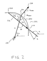
- FIG. 2 illustrates a contour that has been extracted, for example, from a pattern image during the training process.
- contour 202 includes a plurality of contour points 204 , which lie along contour 202 .
- Index point 206 located at (x 0 , y 0 )
- index point 206 which is a contour point
- two reference points back point 208 (located at (x 1 , y 1 ), and “behind” index point 206 by a constant k)
- front point 210 located at (x 2 , y 2 ), and “in front of” index point 206 by a constant k (not shown)
- Variable k controls the locality of the curvature measurement.
- k represents the number of contour points that separate back point 208 from index point 206 , which is the same as the number of contour points separating front point 210 from index point 206 .
- a smaller value for k gives very local curvature measurements, while a larger value for k gives more global measurements.
- indices of front point 208 and back point 210 may be selected automatically. In general, they are separated from index of index point 206 by k (i.e., each is k data points away from index point 206 ).
- k is chosen based upon the severity of the curves in the pattern contours and based upon the number of contour points that are used to represent the contour. Generally, a smaller k may be preferred, but k must not be too small. A k of 10 will work in most standard applications.
- Stick vector 212 which is a vector that connects back point 208 and front point 210 , has a direction representing the direction of “crawl;” that is, the direction from back point 208 to front point 210 .
- Stick vector 212 has an angle of ⁇ 0 relative to the horizontal axis.
- an additional back point (not shown) and an additional front point (not shown) may also be used.
- these points may be indexed with a value greater than k.
- These points may be used to define an additional stick vector (not shown), which may provide additional information regarding contour 202 .
- Line 209 connects index point 206 and back point 208
- line 211 connects index point 206 and front point 210
- Angle ⁇ 2 represents the angle between stick 212 and line 211 .
- Algorithm reference point 214 located at (x C , y C ), may be selected by a user, or it may be the centroid of the pattern, as will be discussed in greater detail below.
- a distance h represents a contour curvature measure for contour point 206 .
- the distance h is the shortest distance from index point 206 to stick 212 .
- Vector R may be constructed by drawing a vector from contour point 206 to algorithm reference point 214 . This vector has magnitude of d, a direction pointing from contour point 206 to algorithm reference point 214 , and angle ⁇ 1 relative to the horizontal axis. Angle ⁇ is the angle between R and stick vector 212 . Angle ⁇ may also be referred to as the “SR Angle.” Angle ⁇ is rotation invariant. This means that regardless of any rotation of contour 202 (or rotation of the part/object) relative to the horizontal axis, this angle is the same for a particular point on contour 202 . Because angle ⁇ is rotation invariant, it is an ideal variable, as it reduces search time significantly. It also eliminates the need for a separate table for each angle of rotation.
- Angle ⁇ Gradient is the angle between gradient 216 and vector R. This may also be referred to as the “GR Angle.”
- ⁇ Gradient determines the position of algorithm reference point 214 relative to stick vector 212 (i.e., (on what side of stick vector 212 ) so long as contour 202 is crawled on in the same direction when training and when searching. Crawling in the same direction may not happen in every image, due to disconnection or extra connection of a contour.
- lengths and angles identified above may be determined by trigonometry, or by other higher-level mathematics.
- step 302 the system is “trained” on a pattern image.
- step 402 a flowchart of the training process is provided.
- step 402 pattern contours are extracted from the pattern image. In one embodiment, this may be achieved by detecting the levels of the edges on the pattern image, which computes the optimal value for the edge level (i.e., the edge strength) in order to filter out noise edge pixels. Other filters may be used as desired.
- Pattern contours may be extracted from the pattern image, preferably after any conditioning.
- an extraction engine such as EdgeCrawler, developed by Imaging Technology, Inc., of Bedford, Mass.
- the extraction engine may extract edge pixels by running a Gaussian filter followed by a Sobel transform. Non-maxima suppression may be performed on all edge points above the value of the level detected by the edge level detection.
- a top-down crawler may be used to create a contour from the edges.
- the edges may be extracted by locating at least one edge of the pattern image of the scene image and recording a starting point for the edge. The edge is then “crawled” along; that is, each pixel along the edge is analyzed. As the pixels are analyzed, they may be extracted from the edge, and then may be filtered. A contour may then be created from the filtered and extracted pixels.
- the extracted contours may be conditioned. This step helps to identify and add undetected edge points, if any.
- aliased edge points may be removed.
- each contour may be spatially filtered with a 5 ⁇ 1 filter. Of course, different filters may be used.
- Each contour may then be normalized to create a new set of contours in which the distance between any neighboring points is 1.0 (one) pixel.
- Raw contour points may have a spacing that varies between 1 and 1.41 pixels in distance, depending on the angle between points.
- the result of the contour conditioning stage is at least one pattern contour.
- an algorithm reference (x, y) position may be selected. Step 406 may be exercised before step 404 , or even after step 408 .
- the reference point may be the centroid coordinate, or central moment, of the pattern contour(s).
- the algorithm reference point may be translated back to user coordinates.
- the pattern contour may be optimized. This may be accomplished by setting levels based on the analysis of pattern contours, including the number of contour points, the curvature statistics of contour points, etc. These points may be used to determine the values of each parameter.
- a reference table is created. This may be performed simultaneously with step 408 . This may be accomplished by analyzing every contour in the pattern contours, and for every point on the contour, extracting the contour curvature, h, the vector R (r, ⁇ 1 ), the angle between the R vector and the stick vector ⁇ , and the angle ⁇ Gadient . In one embodiment, these values may be grouped in a reference table according to their contour curvature h in order to decrease search time, and to better shape the peak shape in the pattern location image, discussed below.
- each rectangle may include data represented generically by variable.
- the fact that the identical variables are shown in the table is not intended to suggest that each measurement for the variables are identical.
- the reference table and related information may be stored in a database.
- the database may include a plurality of reference tables for different pattern images.
- a scene image is acquired.
- the scene image may be acquired in real-time; in other embodiments, the scene image may be acquired from a database, or provided to the system form an outside source.
- step 308 the scene image is searched.
- the scene image is searched.
- FIG. 5 a flowchart of the search process is provided.
- contours are extracted from the scene image.
- contours may be extracted from the scene image in the same way that contours were extracted from the pattern image. Therefore, a detailed description of this step is omitted.
- the contours may be conditioned and/or normalized.
- contours may be conditioned and/or normalized from the scene image in the same way that contours were conditioned and/or normalized from the pattern image. Therefore, a detailed description of this step is omitted.
- step 506 as the contour points are crawled, the values of h, ⁇ 0 , and ⁇ Gradient for each contour point are determined.
- step 508 the location of a potential reference point is computed from scene ⁇ 0 (the angle between a scene stick and the horizontal axis) and R (r, ⁇ 1 ) of a cell in the table.
- the scene contour curvature value, h may be used to select a column of the table.
- a potential reference point for the scene pattern is calculated for each table cell in that column (all the points with the same contour curvature value h).
- the potential reference point (x, y) is entered into a reference point accumulator which “counts” each instance of a potential reference point.
- a pattern location image in which the pixel value at the reference coordinates is incremented each time a calculation yields a reference point with that coordinate, is used as the accumulator.
- the “height” of a particular coordinate increases each time the particular coordinate is calculated as a potential reference point. In one embodiment, this step may be repeated for each of the scene contour points.
- FIG. 6 a An example of a pattern location image is provided in FIG. 6 a .
- the tallest column reflects an accumulator that shows the greatest number of “hits,” and hence, the greater likelihood of a match.
- the angle of rotation of the pattern may be computed. This angle may be computed based upon the angle difference between ⁇ 0 (stick vector angle) of scene point, and ⁇ 0 in the table cell. This angle is also entered into an angle accumulator, which tallies each instance of an angle. In one embodiment, a pattern angle image in which the angle value is stored (stacked) at computed (x, y) coordinates may be used.
- the angle difference between ⁇ Gradient of the scene point, and ⁇ Gradient in the table cell may be used. In general, however, ⁇ 0 may be more stable than ⁇ Gradient .
- FIG. 6 b An example of a pattern angle image is provided in FIG. 6 b.
- step 512 after all points are processed, the accumulator for the potential reference point is analyzed to determine the best potential reference point.
- the angle of rotation is determined.
- a clustering algorithm may be used to determine the angle of rotation.
- the clustering algorithm may return a predetermined number of strong “peaks,” as well as smaller peaks near a strong peak.
- the clustering algorithm may average the peaks to return the most likely angle of rotation.
- edges may be verified.
- the position of all edge points for the potential reference point may be translated into the coordinates of the scene. This may be done by moving a position of the potential pattern to the potential reference point, and then rotating the potential pattern using the angle returned by the search.
- the two sets of edge points may overlap spatially. The movement and the rotation should cause the edges of the potential pattern and the pattern image to overlap.
- the verification procedure verifies that, for each model edge point, there is a corresponding edge point in the scene.
- the number of edge points that verified positive i.e., aligned or matched
- number of points that verified negative i.e., did not align or did not match
- the score is or 0.909, or 90.9%.
- the score may be used to determine whether or not the potential reference point is satisfactory.
- the present invention may be implemented using an image capture device, such as a digital camera, as well as a processor.
- a processor is a Pentium®-series processor, manufactured by Intel, Inc., Santa Clara, Calif.
- ASIC application-specific integrated circuit
- DSP digital signal processor
- Other processor types may be used as desired.
- FIG. 7 depicts a pattern that is to be trained; specifically, this figure includes sample shutter part 702 .
- shutter 702 has reference point 802 , as well as index points 804 , 806 , 808 , 810 , 812 , and 814 .
- Each index point i (x0 i , y0 i ) has a front point (x2 i , y2 i ) and a back point (x1 i , y1 i ), which are each connected by a stick vector.
- h i ⁇ square root over (( x 2 i ⁇ x 0 i ) 2 +( y 2 i ⁇ y 0 i ) 2 ) ⁇ square root over (( x 2 i ⁇ x 0 i ) 2 +( y 2 i ⁇ y 0 i ) 2 ) ⁇ sin( ⁇ i )
- h [ 8.387 1.061 5.13 - 0.906 4.649 - 0.707 ]
- the reference table is created.
- a scene image is provided.
- the contours are extracted and processed.
- several edge points have been selected to show computations in detail.
- the coordinates of the index points i, with their respective back points and front points, are:
- the angle of each stick vector with respect to the x-axis, ⁇ 0 , the angle ⁇ 2 , and the contour curvature hr for each point, i is determined in the same manner described above.
- the potential reference points (xcfound i , ycfound i ) are added to an accumulator. Referring to FIG. 12 , an image of the accumulator is provided. For the angles of rotation, the same process is repeated.
Abstract
Description
| h = 0 | h = 1 | h = 2 | h = 3 | ||
| r | r | r | r | ||
| θ1 | θ1 | θ1 | θ1 | ||
| δθ | δθ | δθ | δθ | ||
| δθGradient | δθGradient | δθGradient | δθGradient | ||
| r | r | r | |||
| θ1 | θ1 | θ1 | |||
| δθ | δθ | δθ | |||
| δθGradient | δθGradient | δθGradient | |||
| r | r | ||||
| θ1 | θ1 | ||||
| δθ | δθ | ||||
| δθGradient | δθGradient | ||||
| r | |||||
| θ1 | |||||
| δθ | |||||
| δθGradient | |||||
| The points | back points | front points |
| x0i := | y0i := | x1i := | y1i := | x2i := | y2i := |
| 211.51 | 198.79 | 209.60 | 214.65 | 226.55 | 193.37 |
| 272.20 | 255.50 | 287.68 | 257.52 | 257.44 | 251.46 |
| 310.51 | 252.06 | 315.91 | 240.71 | 295.49 | 258.13 |
| 315.12 | 196.70 | 314.50 | 186.36 | 318.16 | 211.00 |
| 337.74 | 143.04 | 326.81 | 129.85 | 338.54 | 156.32 |
| 271.44 | 164.44 | 262.71 | 174.34 | 280.55 | 151.78 |
⊖0i arctan [x2i −x1i,(y2i −y1i)−1]
⊖1i:=arctan[x0i −xc,−(y0i −yc)]
r i=√{square root over ((xc−x0i)2+(yc−y0i)2)}{square root over ((xc−x0i)2+(yc−y0i)2)}
⊖2i=arctan[x2i −x0i,−(y2i −y0i)]
h i:=√{square root over ((x2i −x0i)2+(y2i −y0i)2)}{square root over ((x2i −x0i)2+(y2i −y0i)2)}·sin(αi)
| x0i := | y0i := | x1i := | y1i := | x2i := | y2i := |
| 454.44 | 320.86 | 459.39 | 306.41 | 439.14 | 325.28 |
| 404.46 | 256.85 | 389.00 | 251.44 | 417.90 | 262.40 |
| 365.49 | 253.50 | 358.95 | 264.30 | 381.54 | 249.97 |
| 353.11 | 307.43 | 352.36 | 318.21 | 352.21 | 293.48 |
| 321.81 | 357.01 | 331.54 | 370.95 | 324.09 | 343.99 |
| 390.35 | 345.81 | 400.95 | 338.31 | 380.08 | 357.62 |
θ10:=θ00+δθ0
xcfound 0 :=x00 −r 0·cos (θ10) xcfound 0=381.741
ycfound 0 :=y00 +r 0·sin(θ10) ycfound 0=316.883
rotAngle 0:=θ0r 0−θ00 rotAngle 0=3.29
θ12:=θ02+δθ2
xcfound 2 :=x02 −r 2·cos (θ12) xcfound 2=383.297
ycfound 2 :=y02 +r 2·sin(θ12) ycfound 2=316.689
rotAngle 2:=θ0r 1−θ02 rotAngle 2=3.001
θ14:=θ04+δθ4
xcfound 4 :=x04 −r 4·cos (θ14) xcfound 4=382.163
ycfound 4 :=y04 +r 4·sin(θ14) ycfound 4=316.481
rotAngle 4:=θ0r 4−θ04 rotAngle 4=2.994
θ11:=θ01+δθ1
xcfound 1 :=x02 −r 1·cos (θ11) xcfound 1=382.408
ycfound 1 :=y01 +r 1·sin(θ11) ycfound 1=317.556
rotAngle 1:=θ0r 1−θ01 rotAngle 1=3.306
θ15:=θ05+δθ5
xcfound 5 :=x05 −r 5·cos (θ15) xcfound 5=382.199
ycfound 5 :=y05 +r 5·sin(θ15) ycfound 5=316.64
rotAngle 5:=θ0r 5−θ05 rotAngle 5=3.297
θ13:=θ03+δθ3
xcfound 3 :=x03 −r 3·cos (θ13) xcfound 3=383.257
ycfound 3 :=y03 +r 3·sin(θ13) ycfound 3=316.469
rotAngle 3:=θ0r 3−θ03 rotAngle 3=−3
Claims (15)
Priority Applications (3)
| Application Number | Priority Date | Filing Date | Title |
|---|---|---|---|
| US09/680,052 US7006694B1 (en) | 2000-10-05 | 2000-10-05 | System and method for pattern identification |
| PCT/US2001/031081 WO2002029712A2 (en) | 2000-10-05 | 2001-10-05 | System and method for pattern identification |
| AU1142302A AU1142302A (en) | 2000-10-05 | 2001-10-05 | System and method for pattern identification |
Applications Claiming Priority (1)
| Application Number | Priority Date | Filing Date | Title |
|---|---|---|---|
| US09/680,052 US7006694B1 (en) | 2000-10-05 | 2000-10-05 | System and method for pattern identification |
Publications (1)
| Publication Number | Publication Date |
|---|---|
| US7006694B1 true US7006694B1 (en) | 2006-02-28 |
Family
ID=24729445
Family Applications (1)
| Application Number | Title | Priority Date | Filing Date |
|---|---|---|---|
| US09/680,052 Expired - Fee Related US7006694B1 (en) | 2000-10-05 | 2000-10-05 | System and method for pattern identification |
Country Status (3)
| Country | Link |
|---|---|
| US (1) | US7006694B1 (en) |
| AU (1) | AU1142302A (en) |
| WO (1) | WO2002029712A2 (en) |
Cited By (9)
| Publication number | Priority date | Publication date | Assignee | Title |
|---|---|---|---|---|
| US20060007232A1 (en) * | 2004-07-07 | 2006-01-12 | Layne Geary J | System and method for smoothing and compression of polyline data |
| US20080107345A1 (en) * | 2006-11-07 | 2008-05-08 | Simon Melikian | System and method for visual searching of objects using lines |
| US20120143856A1 (en) * | 2009-08-18 | 2012-06-07 | Osaka Prefecture University Public Corporation | Method for detecting object |
| US20120213444A1 (en) * | 2008-04-11 | 2012-08-23 | Recognition Robotics | System and method for visual recognition |
| US8682077B1 (en) | 2000-11-28 | 2014-03-25 | Hand Held Products, Inc. | Method for omnidirectional processing of 2D images including recognizable characters |
| US9495363B1 (en) * | 2010-06-28 | 2016-11-15 | Open Invention Network Llc | System and method for search with the aid of images associated with product categories |
| US9576217B2 (en) | 2008-04-11 | 2017-02-21 | Recognition Robotics | System and method for visual recognition |
| US10902568B2 (en) | 2015-11-02 | 2021-01-26 | Cognex Corporation | System and method for finding lines in an image with a vision system |
| US10937168B2 (en) * | 2015-11-02 | 2021-03-02 | Cognex Corporation | System and method for finding and classifying lines in an image with a vision system |
Families Citing this family (4)
| Publication number | Priority date | Publication date | Assignee | Title |
|---|---|---|---|---|
| US7116823B2 (en) | 2002-07-10 | 2006-10-03 | Northrop Grumman Corporation | System and method for analyzing a contour of an image by applying a Sobel operator thereto |
| US7149356B2 (en) | 2002-07-10 | 2006-12-12 | Northrop Grumman Corporation | System and method for template matching of candidates within a two-dimensional image |
| US7146057B2 (en) | 2002-07-10 | 2006-12-05 | Northrop Grumman Corporation | System and method for image analysis using a chaincode |
| GB0616293D0 (en) | 2006-08-16 | 2006-09-27 | Imp Innovations Ltd | Method of image processing |
Citations (7)
| Publication number | Priority date | Publication date | Assignee | Title |
|---|---|---|---|---|
| US4648024A (en) * | 1983-11-15 | 1987-03-03 | Mitsubishi Denki Kabushiki Kaisha | Curvilinear interpolation system and method |
| US4901362A (en) * | 1988-08-08 | 1990-02-13 | Raytheon Company | Method of recognizing patterns |
| US5033099A (en) * | 1989-07-31 | 1991-07-16 | Agency Of Industrial Science And Technology | Image recognition system |
| US5351310A (en) | 1991-05-21 | 1994-09-27 | International Business Machines Corporation | Generalized shape autocorrelation for shape acquisition and recognition |
| US5600733A (en) * | 1993-11-01 | 1997-02-04 | Kulicke And Soffa Investments, Inc | Method for locating eye points on objects subject to size variations |
| US5611036A (en) * | 1990-11-30 | 1997-03-11 | Cambridge Animation Systems Limited | Apparatus and method for defining the form and attributes of an object in an image |
| US5943441A (en) * | 1995-12-06 | 1999-08-24 | Cognex Corporation | Edge contour tracking from a first edge point |
-
2000
- 2000-10-05 US US09/680,052 patent/US7006694B1/en not_active Expired - Fee Related
-
2001
- 2001-10-05 AU AU1142302A patent/AU1142302A/en active Pending
- 2001-10-05 WO PCT/US2001/031081 patent/WO2002029712A2/en active Application Filing
Patent Citations (7)
| Publication number | Priority date | Publication date | Assignee | Title |
|---|---|---|---|---|
| US4648024A (en) * | 1983-11-15 | 1987-03-03 | Mitsubishi Denki Kabushiki Kaisha | Curvilinear interpolation system and method |
| US4901362A (en) * | 1988-08-08 | 1990-02-13 | Raytheon Company | Method of recognizing patterns |
| US5033099A (en) * | 1989-07-31 | 1991-07-16 | Agency Of Industrial Science And Technology | Image recognition system |
| US5611036A (en) * | 1990-11-30 | 1997-03-11 | Cambridge Animation Systems Limited | Apparatus and method for defining the form and attributes of an object in an image |
| US5351310A (en) | 1991-05-21 | 1994-09-27 | International Business Machines Corporation | Generalized shape autocorrelation for shape acquisition and recognition |
| US5600733A (en) * | 1993-11-01 | 1997-02-04 | Kulicke And Soffa Investments, Inc | Method for locating eye points on objects subject to size variations |
| US5943441A (en) * | 1995-12-06 | 1999-08-24 | Cognex Corporation | Edge contour tracking from a first edge point |
Non-Patent Citations (17)
| Title |
|---|
| Ansari et al., "On Detecting Dominant Points," Pattern Recognition, vol. 24, No. 5, pp. 441-451, 1991. |
| Ayache et al., "HYPER: A New Approach for the Recognition and Positioning of Two-Dimensional Objects," IEEE Transactions on Pattern Analysis and Machine Intelligence, vol. PAMI-8, No. 1, pp. 44-54, 1986. |
| Ballard, "Generalizing the Hough Transform to Detect Arbitrary Shapes," Pattern Recognition, vol. 13, No. 2, pp. 111-122, 1981. |
| Bunke et al., "Applications of Approximate String Matching to 2D Shape Recognition," Pattern Recognition, vol. 26, No. 12, 1797-1812, 1993. |
| Cass, "Polynomial-Time Geometric Matching for Object Recognition," International Journal of Computer Vision, 21 (1/2), pp. 37-61, 1997. |
| Chapter 4, Boundary Detection, pp. 128-131. |
| D.H. Ballard, "Generalizing The Hough Transform To Detect Arbitary Shapes", Sep. 23, 1980, pp. 111-122. |
| Gupta et al., "A New Approach for Aggregating Edge Points into Line Segments," Pattern Recognition, vol. 26, No. 7, pp. 1069-1086, 1993. |
| Henikoff et al., "Representative Patterns for Model-Based Matching," Pattern Recognition, vol. 26, No. 7, pp. 1087-1098, 1993. |
| Huttenlocher et al., "Recognizing Solid Objects by Alignment with an Image," International Journal of Computer Vision, vol. 5, No. 2, pp. 195-212, 1990. |
| Machine Vision: Theory, Algorithms, Practicalities, Circle Detection, pp. 207-212. |
| Pao et al., "Shapes Recognition Using the Straight Line Hough Transform: Theory and Generalization," IEEE Transactions on Pattern Analysis and Machine Intelligence, vol. 14, No. 11, pp. 1076-1089, 1992. |
| Pikaz et al., "Matching of Partially Occluded Planar Curves," Pattern Recognition, vol. 28, pp. 199-209, 1995. |
| Pikaz et al., "Optimal Polygonal Approximation of Digital Curves," Pattern Recognition, vol. 28, No. 3, pp. 373-379, 1995. |
| Toet et al., "Genetic contour matching," Pattern Recognition Letters, No. 16, pp. 849-856, 1995. |
| Tsai, "Locating Overlapping Industrial Parts for Robotic Assembly," Int. J. Adv. Manuf. Technol., vol. 12, pp. 288-302, 1996. |
| Wen et al., "Recognition and Inspection of Manufactured Parts Using the Line Moments of Their Boundaries," Pattern Recognition, vol. 26, No. 10, pp. 1461-1471, 1993. |
Cited By (16)
| Publication number | Priority date | Publication date | Assignee | Title |
|---|---|---|---|---|
| US8682077B1 (en) | 2000-11-28 | 2014-03-25 | Hand Held Products, Inc. | Method for omnidirectional processing of 2D images including recognizable characters |
| US20060007232A1 (en) * | 2004-07-07 | 2006-01-12 | Layne Geary J | System and method for smoothing and compression of polyline data |
| US8787678B2 (en) * | 2006-11-07 | 2014-07-22 | Reognition Robotics | System and method for visual searching of objects using lines |
| US20080107345A1 (en) * | 2006-11-07 | 2008-05-08 | Simon Melikian | System and method for visual searching of objects using lines |
| US7831098B2 (en) * | 2006-11-07 | 2010-11-09 | Recognition Robotics | System and method for visual searching of objects using lines |
| US20110052046A1 (en) * | 2006-11-07 | 2011-03-03 | Recognition Robotics, Inc. | System and method for visual searching of objects using lines |
| US20120213444A1 (en) * | 2008-04-11 | 2012-08-23 | Recognition Robotics | System and method for visual recognition |
| US9576217B2 (en) | 2008-04-11 | 2017-02-21 | Recognition Robotics | System and method for visual recognition |
| US8768065B2 (en) * | 2008-04-11 | 2014-07-01 | Simon Melikian | System and method for visual recognition |
| US20120143856A1 (en) * | 2009-08-18 | 2012-06-07 | Osaka Prefecture University Public Corporation | Method for detecting object |
| US8533162B2 (en) * | 2009-08-18 | 2013-09-10 | Osaka Prefecture University Public Corporation | Method for detecting object |
| US9495363B1 (en) * | 2010-06-28 | 2016-11-15 | Open Invention Network Llc | System and method for search with the aid of images associated with product categories |
| US10902568B2 (en) | 2015-11-02 | 2021-01-26 | Cognex Corporation | System and method for finding lines in an image with a vision system |
| US10937168B2 (en) * | 2015-11-02 | 2021-03-02 | Cognex Corporation | System and method for finding and classifying lines in an image with a vision system |
| US11699283B2 (en) | 2015-11-02 | 2023-07-11 | Cognex Corporation | System and method for finding and classifying lines in an image with a vision system |
| US11854173B2 (en) | 2015-11-02 | 2023-12-26 | Cognex Corporation | System and method for finding lines in an image with a vision system |
Also Published As
| Publication number | Publication date |
|---|---|
| WO2002029712A3 (en) | 2002-07-04 |
| WO2002029712A2 (en) | 2002-04-11 |
| AU1142302A (en) | 2002-04-15 |
Similar Documents
| Publication | Publication Date | Title |
|---|---|---|
| Holz et al. | Registration with the point cloud library: A modular framework for aligning in 3-D | |
| EP1658579B1 (en) | Method for for classification and spatial localization of bounded 3d-objects | |
| US7376262B2 (en) | Method of three dimensional positioning using feature matching | |
| JP2919284B2 (en) | Object recognition method | |
| Agrawal et al. | Censure: Center surround extremas for realtime feature detection and matching | |
| Drost et al. | 3d object detection and localization using multimodal point pair features | |
| US6278798B1 (en) | Image object recognition system and method | |
| US7006694B1 (en) | System and method for pattern identification | |
| Tell et al. | Wide baseline point matching using affine invariants computed from intensity profiles | |
| CN109583357B (en) | Face recognition method for improving LBP (local binary pattern) and lightweight convolutional neural network cascade | |
| David et al. | Object recognition in high clutter images using line features | |
| EP2534612B1 (en) | Efficient scale-space extraction and description of interest points | |
| Tombari et al. | Hough voting for 3d object recognition under occlusion and clutter | |
| CN106558072A (en) | A kind of method based on SIFT feature registration on remote sensing images is improved | |
| CN102722731A (en) | Efficient image matching method based on improved scale invariant feature transform (SIFT) algorithm | |
| CN112598922B (en) | Parking space detection method, device, equipment and storage medium | |
| Benseddik et al. | SIFT and SURF Performance evaluation for mobile robot-monocular visual odometry | |
| Ghita et al. | A bin picking system based on depth from defocus | |
| Sehgal et al. | Real-time scale invariant 3D range point cloud registration | |
| US7388990B2 (en) | Local mass distribution partitioning for object recognition | |
| US20180121757A1 (en) | System and method for automated object recognition | |
| Paffenholz et al. | Geo-referencing point clouds with transformational and positional uncertainties | |
| US20070071325A1 (en) | Systems and methods for recognizing objects in an image | |
| CN110769221B (en) | Method for detecting corner of projected image in photographed image and projector | |
| West et al. | Using symmetry, ellipses, and perceptual groups for detecting generic surfaces of revolution in 2D images |
Legal Events
| Date | Code | Title | Description |
|---|---|---|---|
| AS | Assignment |
Owner name: CORECO IMAGING, INC., MASSACHUSETTS Free format text: ASSIGNMENT OF ASSIGNORS INTEREST;ASSIGNORS:MELIKIAN, SIMON H.;TYMINSKI, DAREN;REEL/FRAME:011432/0300;SIGNING DATES FROM 20010102 TO 20010104 |
|
| AS | Assignment |
Owner name: CORECO IMAGING, INC., MASSACHUSETTS Free format text: ASSIGNMENT OF ASSIGNORS INTEREST;ASSIGNOR:DAWSON, BENJAMIN M.;REEL/FRAME:015858/0003 Effective date: 20041004 |
|
| FPAY | Fee payment |
Year of fee payment: 4 |
|
| FPAY | Fee payment |
Year of fee payment: 8 |
|
| FEPP | Fee payment procedure |
Free format text: PAYER NUMBER DE-ASSIGNED (ORIGINAL EVENT CODE: RMPN); ENTITY STATUS OF PATENT OWNER: LARGE ENTITY Free format text: PAYOR NUMBER ASSIGNED (ORIGINAL EVENT CODE: ASPN); ENTITY STATUS OF PATENT OWNER: LARGE ENTITY |
|
| AS | Assignment |
Owner name: DALSA INDUSTRIAL PRODUCTS INC., CALIFORNIA Free format text: CHANGE OF NAME;ASSIGNOR:CORECO IMAGING, INC.;REEL/FRAME:032694/0442 Effective date: 20061128 Owner name: TELEDYNE DALSA INDUSTRIAL PRODUCTS, INC., CALIFORN Free format text: CHANGE OF NAME;ASSIGNOR:DALSA INDUSTRIAL PRODUCTS INC.;REEL/FRAME:032694/0429 Effective date: 20110218 |
|
| FEPP | Fee payment procedure |
Free format text: MAINTENANCE FEE REMINDER MAILED (ORIGINAL EVENT CODE: REM.) |
|
| LAPS | Lapse for failure to pay maintenance fees |
Free format text: PATENT EXPIRED FOR FAILURE TO PAY MAINTENANCE FEES (ORIGINAL EVENT CODE: EXP.) |
|
| STCH | Information on status: patent discontinuation |
Free format text: PATENT EXPIRED DUE TO NONPAYMENT OF MAINTENANCE FEES UNDER 37 CFR 1.362 |
|
| FP | Lapsed due to failure to pay maintenance fee |
Effective date: 20180228 |