US7021300B2 - Diagnostic apparatus for an exhaust gas sensor - Google Patents
Diagnostic apparatus for an exhaust gas sensor Download PDFInfo
- Publication number
- US7021300B2 US7021300B2 US10/925,150 US92515004A US7021300B2 US 7021300 B2 US7021300 B2 US 7021300B2 US 92515004 A US92515004 A US 92515004A US 7021300 B2 US7021300 B2 US 7021300B2
- Authority
- US
- United States
- Prior art keywords
- exhaust gas
- gas sensor
- fuel injection
- injection amount
- engine
- Prior art date
- Legal status (The legal status is an assumption and is not a legal conclusion. Google has not performed a legal analysis and makes no representation as to the accuracy of the status listed.)
- Active
Links
Images


Classifications
-
- F—MECHANICAL ENGINEERING; LIGHTING; HEATING; WEAPONS; BLASTING
- F02—COMBUSTION ENGINES; HOT-GAS OR COMBUSTION-PRODUCT ENGINE PLANTS
- F02D—CONTROLLING COMBUSTION ENGINES
- F02D41/00—Electrical control of supply of combustible mixture or its constituents
- F02D41/02—Circuit arrangements for generating control signals
- F02D41/14—Introducing closed-loop corrections
- F02D41/1438—Introducing closed-loop corrections using means for determining characteristics of the combustion gases; Sensors therefor
- F02D41/1444—Introducing closed-loop corrections using means for determining characteristics of the combustion gases; Sensors therefor characterised by the characteristics of the combustion gases
- F02D41/1454—Introducing closed-loop corrections using means for determining characteristics of the combustion gases; Sensors therefor characterised by the characteristics of the combustion gases the characteristics being an oxygen content or concentration or the air-fuel ratio
-
- F—MECHANICAL ENGINEERING; LIGHTING; HEATING; WEAPONS; BLASTING
- F02—COMBUSTION ENGINES; HOT-GAS OR COMBUSTION-PRODUCT ENGINE PLANTS
- F02D—CONTROLLING COMBUSTION ENGINES
- F02D41/00—Electrical control of supply of combustible mixture or its constituents
- F02D41/02—Circuit arrangements for generating control signals
- F02D41/14—Introducing closed-loop corrections
- F02D41/1438—Introducing closed-loop corrections using means for determining characteristics of the combustion gases; Sensors therefor
- F02D41/1493—Details
- F02D41/1495—Detection of abnormalities in the air/fuel ratio feedback system
-
- F—MECHANICAL ENGINEERING; LIGHTING; HEATING; WEAPONS; BLASTING
- F02—COMBUSTION ENGINES; HOT-GAS OR COMBUSTION-PRODUCT ENGINE PLANTS
- F02D—CONTROLLING COMBUSTION ENGINES
- F02D41/00—Electrical control of supply of combustible mixture or its constituents
- F02D41/02—Circuit arrangements for generating control signals
- F02D41/14—Introducing closed-loop corrections
- F02D41/1438—Introducing closed-loop corrections using means for determining characteristics of the combustion gases; Sensors therefor
- F02D41/1444—Introducing closed-loop corrections using means for determining characteristics of the combustion gases; Sensors therefor characterised by the characteristics of the combustion gases
- F02D41/1454—Introducing closed-loop corrections using means for determining characteristics of the combustion gases; Sensors therefor characterised by the characteristics of the combustion gases the characteristics being an oxygen content or concentration or the air-fuel ratio
- F02D41/1456—Introducing closed-loop corrections using means for determining characteristics of the combustion gases; Sensors therefor characterised by the characteristics of the combustion gases the characteristics being an oxygen content or concentration or the air-fuel ratio with sensor output signal being linear or quasi-linear with the concentration of oxygen
Definitions
- the present invention relates to a diagnostic apparatus for detecting a degradation failure of an exhaust gas sensor disposed in an exhaust passage of an internal-combustion engine (hereinafter referred to as an “engine”).
- An exhaust gas sensor is generally disposed in an exhaust passage of an engine of a vehicle in order to measure constituent elements of an exhaust gas.
- the exhaust gas sensor produces outputs representing air-fuel ratio of the exhaust gas.
- an electronic control unit of the engine controls the air-fuel ratio of the fuel to be supplied to the engine. Therefore, when the exhaust gas sensor does not produce outputs reflecting a correct air-fuel ratio due to its degradation failure, the control unit cannot perform a correct control of the air-fuel ratio upon the engine.
- a fuel amount indicated by a modulated rectangular waveform is injected into the engine and a response from the engine is used.
- a response which is output responsive to the modulated rectangular waveform containing various frequency components, tends to be influenced by noises. Because such response signals are influenced by operating conditions of the engine, air-fuel ratio variation that may be produced during a transient operation, the frequency of the output signal for evaluating the sensor condition can hardly be kept at a constant level. Therefore, when the sensor condition is evaluated based on such output, evaluation precision may deteriorate.
- precision of the air-fuel ratio control is getting more important than before as emission control is enhanced and the amount of precious metals carried by the catalyst need to be reduced. Accordingly, in order to suppress an increase of the exhaust gas constituent elements due to the characteristic degradation failure of the exhaust gas sensor, it is required to improve the detection precision more than before and it is also required to suppress the increase of the exhaust gas constituent elements during the degradation detection process.
- the present invention provides a deterioration failure diagnostic apparatus for an exhaust gas sensor that is disposed in an exhaust passage of an engine to generate an output corresponding to constituent elements of exhaust gas from the engine.
- the apparatus has detecting signal generating means for generating a detecting signal and multiplying the generated signal to a first basic fuel injection amount to produce a second fuel injection amount.
- the apparatus also includes a feedback representative value calculating means for calculating a feedback representative value based on feedback correction coefficients used at a normal operation time and multiplying it to the second fuel injection amount to produce a final fuel injection amount to be input to the engine.
- the apparatus further includes an exhaust gas sensor evaluating means for extracting from the output of the exhaust gas sensor a frequency response corresponding to the detecting signal.
- the output of the gas sensor is in response to the calculated final fuel injection amount.
- the condition of the exhaust gas sensor is determined based on the extracted frequency response.
- the feedback representative value is a value representing a steady-state deviation of the feedback correction coefficients.
- the ratio of the noise elements contained in the exhaust gas can readily be decreased and the detection precision of the deterioration failure of the exhaust gas sensor may be improved.
- the feedback representative value to correct the fuel injection amount during the deterioration failure detection process, increase of the exhaust gas elements during the detection process may be suppressed in comparison to the case of simply suspending the feedback.
- the feedback representative value is a value representing a steady-state deviation of the feedback correction coefficients used before the start of a process for detecting the degradation failure of the exhaust gas sensor.
- the feedback representative value is an average, a median or a smoothed value of the feedback correction coefficients.
- the fuel injection amount can be corrected by the feedback representative value that is adapted to the characteristic of the engine and accordingly the increase of the exhaust gas elements during the detection process can be suppressed.
- the detecting signal to be multiplied to the first basic fuel injection amount is a signal obtained by adding either a sine wave or a cosine wave or a trigonometric wave to a predetermined offset value.
- signals that are easy to produce are used. While the ratio of the frequency components for the detection is maintained substantial and the magnitude of the detecting frequency components in the exhaust gas is maintained substantial, the response of specific frequencies of the exhaust gas sensor is used for the evaluation purpose so that the detection precision of the deterioration failure of the exhaust gas sensor may be further improved.
- the detecting signal to be multiplied to the first basic fuel injection amount is a signal obtained by adding a composite wave comprising two or more trigonometric function waves to a predetermined offset value.
- a composite wave comprising two or more trigonometric function waves of different frequencies may be employed such that two or more frequency responses may be used for determining the condition of the exhaust gas sensor.
- the trigonometric function wave can be formed to a desired waveform, which is reflected in the fuel injection amount so that the condition of the exhaust gas sensor can be determined. Accordingly, the detection precision of the deterioration failure of the exhaust gas sensor is enhanced.
- the exhaust gas sensor evaluating means determines the condition of the exhaust gas sensor when a predetermined time has elapsed since the fuel injection amount multiplied by the detecting signal was supplied to the engine. According to this aspect of the invention, the determination of the exhaust gas sensor condition can be performed stably by avoiding such unstable state of the exhaust gas air-fuel ratio that may appear at the time immediately after the detecting signal is reflected on the fuel. Accordingly, the detection precision of the deterioration failure of the exhaust gas sensor can be further enhanced.
- the exhaust gas sensor evaluating means determines the condition of the exhaust gas sensor by using an output from the exhaust gas sensor after it has gone through a band-pass filter.
- the frequency components, which are contained in the exhaust gas, except for the detecting frequency are removed because those frequencies are noises when the condition of the exhaust gas sensor is determined. Accordingly, the detection precision of the deterioration failure of the exhaust gas sensor may be enhanced.
- the exhaust gas sensor evaluating means determines that the exhaust gas sensor is a failure when an integral value obtained by integrating absolute values of the bandpass-filtered outputs from the exhaust gas sensor is less than a predetermined value. According to yet another aspect of the invention, the exhaust gas sensor evaluating means determines that the exhaust gas sensor is a failure when a value obtained by smoothing absolute values of the bandpass-filtered outputs from the exhaust gas sensor is less than a predetermined value. Since the variation in the outputs from the exhaust gas sensor can be thus averaged according to these aspects of the invention, the detection precision of the deterioration failure of the exhaust gas sensor may be further enhanced.
- the feedback coefficient is determined based on an output of either an exhaust gas sensor disposed upstream of a catalytic converter or an exhaust gas sensor disposed downstream of the catalytic converter. Outputs from the two exhaust gas sensors disposed upstream and downstream of the catalytic converter respectively may be used to determine the feedback coefficient.
- a drift toward rich or lean which may be caused by correcting the fuel injection amount by applying the detecting signal to the fuel injection amount may be suppressed.
- FIG. 1 is a schematic diagram showing an exhaust gas sensor failure diagnostic apparatus according to one embodiment of the present invention.
- FIG. 2 shows an example of an ECU to be used in an exhaust gas sensor failure diagnostic apparatus according to one embodiment of the present invention.
- FIG. 3 shows a flowchart of one embodiment of the present invention.
- FIG. 4 schematically shows an example of a frequency characteristic of a bandpass filter used in the present invention.
- FIG. 5 schematically shows an example of extraction of a detecting frequency fid.
- FIG. 6 schematically shows an example of calculation of a LAF sensor responsiveness parameter LAF_DLYP.
- FIG. 7 schematically shows an example of calculation of a LAF sensor responsiveness parameter LAF_AVE.
- FIG. 8 is a schematic diagram showing an exhaust gas sensor failure diagnostic apparatus when a composite wave is used.
- FIG. 9 shows examples of input composite waves.
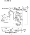
- FIG. 10 is a schematic diagram showing an exhaust gas sensor failure diagnostic apparatus using a feedback of both outputs of before-catalyst and after-catalyst exhaust gas sensors.
- FIG. 1 is a schematic diagram of an overall structure for describing a concept of the present invention.
- a detecting-signal generating unit 10 has a function of generating a predetermined detecting signal KIDSIN in which a trigonometric function wave FDSIN or the like is superimposed on an offset value IDOFT.
- a responsiveness evaluating unit 105 has a function of performing a bandpass filtering upon an equivalence ratio KACT, which is an output from a wide-range linear air-fuel ratio sensor (hereinafter referred to as an LAF sensor) 103 , then converting the filtered value to an absolute value, further integrating the converted values over a predetermined time period and finally transmitting this integral value to an exhaust gas sensor evaluating unit.
- the exhaust gas sensor evaluating unit has a function of determining a degradation failure of an exhaust gas sensor based on the transmitted values.
- a feedback compensation unit 104 has a function of generating a feedback correction coefficient KAF to be used for keeping the air-fuel ratio at an appropriate level based on the output value from the LAF sensor 103 . This calculation operation of the feedback compensation unit is suspended during a process for detecting a deterioration failure of the exhaust gas sensor.
- a feedback representative value calculating unit 109 uses the feedback correction coefficients KAF calculated by the feedback compensation unit 104 to calculate a feedback representative value KAFCENTER that is a representative value of those coefficients.
- KAFCENTER may be either an average, a median or a smoothed value of the feedback correction coefficients KAF, so it is a value representing mainly the steady-state deviation of the feedback correction coefficients.
- the feedback compensation unit 104 suspends its calculation of the feedback correction coefficient during the degradation failure detection of the exhaust gas sensor. Instead of the feedback correction coefficient, this feedback representative value is used as a coefficient to be multiplied to the second basic fuel injection amount containing the detecting signal so as to generate a final fuel injection amount.
- the feedback representative value calculating unit 109 continues its operation for calculating the feedback representative value during the normal operation, but it suspends the calculation of the feedback representative value during the degradation failure detection process and holds the feedback representative value generated just before the suspension of the calculation.
- the above-described functions of the exhaust gas sensor evaluating unit, the detecting signal generating unit 101 , the feedback compensation unit 104 , the responsiveness evaluating unit 105 and the feedback representative value calculating unit 109 can be implemented in an electronic control unit (ECU), so the operation of each unit will be described in detail later in association with the description of the ECU and the degradation failure diagnostic process for the exhaust gas sensor.
- ECU electronice control unit
- Engine 102 is an internal-combustion engine in which a final fuel injection amount can be controlled by an injection controller based on a value from a fuel amount calculating unit 206 (which will be described later).
- the LAF sensor 103 is a sensor that detects an air-fuel ratio extending over a wide range from rich to lean of the exhaust gas discharged from the engine 102 .
- the output of the LAF sensor 103 is used to generate an equivalence ratio KACT.
- the detecting signal KIDSIN is multiplied to the first basic fuel injection amount during the degradation detection process whereas a value of 1.0 is multiplied except during the degradation detection process.
- the feedback correction coefficient KF is used except during the degradation detection process whereas the feedback representative value KACENTER that is held in the representative unit 109 is used during the degradation detection process.
- Such switching operation is represented by switches 110 , 111 in FIG. 1 and both switches operate simultaneously in synchronization with each other.
- FIG. 2 schematically shows an overall structure of an electronic control unit (ECU) 200 .
- ECU electronice control unit
- the functions of a detecting signal generating unit 202 , an exhaust gas sensor evaluating unit 203 , a responsiveness evaluating unit 204 and a fuel amount calculating unit 206 are integrated into the ECU that controls the engine system although the ECU may be provided as a controller dedicated for diagnosing the failure of the exhaust gas sensor.
- the ECU 200 is essentially a computer and comprises a processor for performing various computations, a Random Access Memory (RAM) for providing storage areas for temporally storing various data and a working space for the computations by the processor, a Read-Only Memory (ROM) for pre-storing programs to be executed by the processor and various data required for the computations.
- the ROM may be a re-writable non-volatile memory for storing computation results by the processor and the data to be stored among the data obtained from each section of the vehicle.
- the non-volatile memory can be implemented in the form of a RAM with a backup capability to which certain voltage is always supplied even when the system is shut down.
- An input interface 201 is an interface unit of the ECU 200 with each section of the engine system.
- the input interface 201 receives information, indicating operating conditions of the vehicle, which is transmitted from various sections of the engine system, performs a signal processing, converts analog information to digital signals and then delivers those signals to the exhaust gas sensor evaluating unit 203 , the responsiveness evaluating unit 204 and the fuel amount calculating unit 206 .
- the KACT value that is output from the LAF sensor 103 , a vehicle speed V, an engine rotational speed Ne, an engine load W and a LAF sensor active signal are shown as inputs to the input interface 201 in FIG. 2 , the inputs are not limited to those parameters. Other parameters may be input.
- the detecting signal generating unit 202 has a function of generating a predetermined signal KIDSIN to be used for detection.
- the signal is generated by adding a trigonometric function wave FDSIN or the like to an offset value IDOFT based on a command from the exhaust gas sensor evaluating unit 203 .
- This detecting signal KIDSIN will be described later in association with a process for diagnosing an exhaust gas sensor failure.
- the exhaust gas sensor evaluating unit 203 performs a necessary calculation and determination of the condition for executing the process for diagnosing the exhaust gas sensor failure based on the data delivered from the input interface 201 (this process will be described later). In addition, the unit 203 controls the detecting signal generating unit 202 , the responsiveness evaluating unit 204 and the fuel amount calculating unit 206 .
- the responsiveness evaluating unit 204 performs a bandpass filtering upon an output KACT from the LAF sensor 103 , converting the filtered value to an absolute value, and then integrates converted values over a predetermined time period.
- the fuel amount calculating unit 206 has a function of receiving the detecting signal KIDSIN generated by the detecting signal generating unit 202 , multiplying the detecting signal to the first basic fuel injection amount to produce the second basic fuel injection amount, further multiplying the feedback correction coefficient (or the feedback representative value) to the second basic fuel injection amount and then providing the resulting final fuel injection amount INJ to the output interface 205 .
- the fuel amount calculating unit 206 includes a feedback compensation function for using the detection value from the exhaust gas sensor to calculate the above-described feedback correction coefficient in order to keep the air-fuel ratio close to a stoichiometric air-fuel ratio as well as a function of calculating a feedback representative value (will be described later).
- the output interface 205 has a function of sending a control signal indicating the fuel injection amount INJ to one or more fuel injectors of the engine. Besides, the output interface 205 sends a control signal from the exhaust gas sensor evaluating unit 203 to a failure lamp.
- the functions of the output interface 205 are not limited to these ones. Other controller or the like may be connected to the output interface 205 .
- a process for an exhaust gas sensor failure diagnosis will now be described.
- a degradation failure of the LAF sensor 103 an exhaust gas sensor, is diagnosed.
- the exhaust gas sensor evaluating unit 203 checks an exhaust gas sensor evaluation completion flag to determine whether or not a degradation failure of the exhaust gas sensor has been already evaluated (S 301 ). Initially, since the evaluation upon the exhaust sensor is not performed yet, the exhaust gas sensor evaluation completion flag is set to 0, so the process proceeds to Step S 302 , in which it is determined whether or not a detection condition is satisfied.
- the detection condition means such state that the vehicle speed, the engine rotational speed and the engine load are within their respective predetermined ranges. Therefore, the exhaust gas sensor evaluating unit 203 obtains the vehicle speed V, the engine rotational speed Ne and the engine load W through the input interface 201 to determine whether or not all of these values are within the respective predetermined ranges. When this condition is not satisfied, the process proceeds to Step S 319 . In this case, since the degradation failure detection is not performed, the feedback correction coefficient at the normal operation time is calculated, and the feedback representative value is calculated in Step S 320 .
- calculation of the feedback correction coefficient KAF is performed based on the output from the LAF sensor.
- the exhaust gas sensor evaluating unit 203 determines whether the final fuel injection amount to be injected by the injection function is lean or rich.
- the fuel amount calculating unit 206 reduces the previously calculated value of the feedback correction coefficient by a constant rate when it is rich, while the unit 206 increases that value by the constant rate when it is lean.
- the correction coefficient may be changed in a form of discrete steps rather than using the constant rate when the signal changes from lean to rich or rich to lean.
- the feedback representative value can be obtained by smoothing the feedback correction coefficients KAF according to the following equation.
- the calculation result is stored and held.
- KAF CENTER (1 ⁇ c 1 ) ⁇ KAF i ⁇ 1 +c 1 ⁇ KAF i where c 1 is a smoothing coefficient.
- a feedback representative value KAFCENTER can be alternatively obtained by using an average or the like of the multiple feedback correction coefficients.
- the representative value KAFCENTER can be calculated according to the following equation:
- KAFCENTER KAF i + KAF i - 1 + ... + KAF i - j i - j + 1 ( 1 )
- a feedback representative value KAFCENTER can be obtained by using a median of the feedback correction coefficients.
- m median values KAF M1 , KAF M2 , . . . , KAF Mm are first derived for each of m groups of n feedback correction coefficients KAF 1 , . . . , KAF n which are ordered in an ascending sequence within each group, and then the median value can be obtained by calculating an average as shown in the following equation:
- KAFCENTER KAF M1 + ... + KAF Mm m ( 2 )
- the responsiveness evaluating unit 204 sends a command to the detecting signal generating unit 202 so as to request for the suspension of the detection signal because the deterioration failure detection is not performed at this time point.
- the detecting signal generating unit 202 sets IDOFT to a constant of 1.0 and FDSIN to a constant value of 0 and then generates a composite signal KIDSIN by adding the IDOFT and the FDSIN together (in this case, the composite signal KIDSIN becomes 1.0).
- the KIDSIN is a coefficient to be multiplied to a first basic fuel injection amount to produce a second basic fuel injection amount as shown in FIG. 1 .
- the exhaust gas sensor evaluating unit 203 sets a predetermined time on a timer TM_KACTFD and starts a countdown of the timer TM_KACTFD (S 322 ).
- the predetermined time to be set on the TM_KACTFD in this step is a time until a response to the fuel injection reflecting the detecting signal is output stably from the engine since the condition for the exhaust gas sensor evaluation has been satisfied (as will be described later) to perform the fuel injection reflecting the detecting signal.
- the timer in order for an integral operation (which will be described later) to start when the predetermined time has elapsed, the response can be evaluated except for such unstable state that may happen just after the detection signal is reflected in the fuel injection amount, so that the detection accuracy can be improved.
- the exhaust gas sensor evaluating unit 203 After setting the TM_KACTFD on the timer, the exhaust gas sensor evaluating unit 203 sets a predetermined time on a timer TM_LAFDET and then starts a countdown of the timer TM_LAFDET.
- the predetermined time to be set on the timer TM_LAFDET is an integration time for performing an integral operation upon absolute values (which will be output in a later stage). The result of the integral operation is to be used to determine the deterioration failure of the exhaust sensor.
- the exhaust gas sensor evaluating unit 203 After setting the timer TM_LAFDET (S 323 ), the exhaust gas sensor evaluating unit 203 resets the exhaust gas sensor evaluation completion flag to 0 (S 324 ) and then terminates this process.
- Step S 319 and Step S 316 means the calculation of the feedback correction coefficients in such normal feedback calculating operations including, for example, suspension of the feedback during a fuel-cut process, but it does not mean a continuation of the calculation of the feedback correction coefficients under all operating conditions.
- Step S 301 When the exhaust gas sensor failure diagnosis process is invoked again by the main program, the process in Step S 301 is performed but the exhaust gas sensor is still not evaluated yet at this time, so the process proceeds to Step S 302 , in which it is determined whether or not the detection condition is satisfied.
- the exhaust gas sensor evaluating unit 203 proceeds the process to Step S 303 in order to prepare for the deterioration detection.
- the sensor evaluating unit 203 sends a command to the fuel injection unit 206 to suspend the calculation of the feedback correction coefficients (S 303 ) and also suspend the calculation of the feedback representative value and hold the feedback representative value calculated at that time point (S 304 ).
- the exhaust gas sensor evaluating unit 203 receives a LAF sensor active signal through the input interface 201 and determines whether or not the LAF sensor 103 has already become active (S 305 ).
- the LAF sensor 103 is not active sufficiently when only a short time elapses after the engine start. Therefore, when a predetermined time does not elapse after the start of the engine, the exhaust gas sensor evaluating unit 203 proceeds the process to S 321 .
- the calculations of the feedback correction coefficients and the feedback representative value are suspended before Step S 305 , the suspension of those calculations must be continued because the LAF sensor 103 is not active yet.
- the operations in Step S 321 and the subsequent steps are same as described above.
- the exhaust gas sensor failure diagnosis process is invoked again by the main program.
- the exhaust gas sensor evaluation completion flag is being reset by the previous process and the exhaust gas sensor becomes active when the predetermined time after the engine start elapses, so the exhaust gas sensor evaluating unit 203 proceeds the process from Step S 301 to Step S 302 in order to perform Step S 303 and Step S 304 in the same manner as above described. Then, the process proceeds to Step S 306 via Step S 305 .
- the exhaust gas sensor evaluating unit 203 sends a request for calculating a KACT_FA to the detecting signal generating unit 202 .
- the detecting signal generating unit 202 Upon receiving the request for the calculation of KACT_FA, the detecting signal generating unit 202 first generates a sine wave IDSIN with a frequency fid (3 Hz is used in this example) and an amplitude aid (0.03 in this example) and then adds an offset amount (1.0 in this example) to the above-generated sine wave IDSIN so as to obtain a KIDSIN (namely, 1.0+0.03*sin 6 ⁇ t) in Step S 306 .
- This value KIDSIN is continuously transmitted to the fuel amount calculating unit 206 .
- the fuel amount calculating unit 206 multiplies the KIDSIN to the first basic fuel injection amount and further multiplies the stored feedback representative value KAFCENTER to the basic fuel amount to obtain a final fuel injection amount INJ.
- This final fuel injection amount INJ is input to the injection function of the engine 102 through the output interface 205 .
- the exhaust gas which is an output corresponding to the final fuel injection amount as an input, is emitted from an exhaust system of the engine.
- the LAF sensor 103 detects the emitted exhaust gas and inputs its output KACT to the responsiveness evaluating unit 204 through the input interface 201 .
- the responsiveness evaluating unit 204 substitutes the KACT into the following equation in order to calculate a bandpass-filtered output KACT_F (S 307 ).
- KACT — F ( k ) a 1 KACT — F ( k ⁇ 1)+ a 2 KACT — F ( k ⁇ 2)+ a 3 KACT — F ( k ⁇ 3)+ b 0 KACT ( k )+ b 1 KACT ( k ⁇ 1)+ b 2 KACT ( k ⁇ 2)+ b 3 KACT ( k ⁇ 3) (3)
- a 1 , a 2 , a 3 , b 0 , b 1 , b 2 and b 3 are filtering coefficients.
- the frequency property of the bandpass filter used here is to pass the frequency of 3 Hz that is the same as the frequency of the detecting signal as shown in FIG. 4 .
- the responsiveness evaluating unit 204 calculates an absolute value KAT_FA from the KACT_F (S 308 ).
- the exhaust gas sensor evaluating unit 203 determines whether or not the timer TM_KACTFD is 0 (S 309 ). When the timer TM_KACTFD is not 0, the exhaust gas sensor evaluating unit 203 proceeds the process to Step S 323 . Operations in Step S 323 and the subsequent steps are the same as described above. On the other hand, when the timer TM_KACTED is 0, the exhaust gas sensor evaluating unit 203 informs the responsiveness evaluating unit 204 that the timer condition is satisfied. Upon such information, the responsiveness evaluating unit 204 calculates the integral value LAF_DLYP successively (S 310 ).
- FIG. 6 shows an example of calculation of LAF_DLYP relative to the continuous time in a horizontal axis.
- the exhaust gas sensor evaluating unit 203 determines whether or not the timer TM_LAFDET is 0. When the timer TM_LAFDET is not 0, the process proceeds to Step S 324 . Operations in Step S 324 and the subsequent steps are same as above described. On the other hand, when the timer TM_LAFDET is 0, the exhaust gas sensor evaluating unit 203 request the responsiveness evaluating unit 204 to suspend the integral calculation of for the value KACT_FA over the predetermined time period, receiving the current value of the calculated integral values LAF_DLYP transmitted from the responsiveness evaluating unit 204 and proceeds the process to Step S 312 .
- Step S 312 the exhaust gas sensor evaluating unit 203 determines whether or not the integral value LAF_DLYP exceeds a predetermined value LAF_DLYP_OK.
- the LAF_DLYP_OK value is a threshold value for determining, based on the integral value LAF_DLYP, whether or not the exhaust gas sensor fails due to deterioration.
- the exhaust gas sensor evaluating unit 203 determines that the exhaust gas sensor is not in a failure by deterioration, sets the exhaust gas sensor evaluation completion flag to 1 (S 313 ) and sends a command to the fuel amount calculating unit 206 to perform the feedback correction coefficient calculation (S 316 ) and the feedback representative value calculation (S 317 ). Then, the exhaust gas sensor evaluating unit 203 sends a request command to the detecting signal generating unit 202 to set the KIDSIN to 1.0 (S 318 ). After the generation of the detecting signal is suspended, this process is terminated.
- the exhaust gas sensor evaluating unit 203 determines that the exhaust gas sensor has failed by deterioration, stores information indicating abnormality of the exhaust gas sensor and turns on an exhaust gas failure lamp through the output interface 205 (S 314 ). Then, the unit 203 sets the exhaust gas sensor evaluation completion flag to 1 (S 315 ) and proceeds the process to Step S 316 . Operations in Step S 316 and the subsequent steps are same as above described.
- Step S 310 rather than determining the degradation failure of the exhaust gas sensor based on the integral value LAF_DLYP, such smoothing calculation is performed as shown in FIG. 7 in which a moving average for the KACT_FA values is calculated, and then the deterioration failure of the exhaust gas sensor may be determined based on such smoothed value LAF_AVE.
- LAF — AVE (1 ⁇ c 2 ) ⁇ KACT — FA i ⁇ 1 +c 2 ⁇ KACT — FA i (4) where c 2 represents a smoothing coefficient.
- Step S 312 the exhaust gas sensor evaluating unit 203 determines whether or not the smoothed value LAF_AVE exceeds a determination value LAF_AVE_OK.
- the smoothed value LAF_AVE does not exceed the determination value LAF_DLYP_OK
- the exhaust gas sensor evaluating unit 203 determines that the exhaust gas sensor is in a failure due to deterioration.
- the value LAF_AVE exceeds the determination value LAF_DLYP_OK
- the exhaust gas sensor evaluating unit 203 determines that the exhaust gas sensor is not in a failure due to deterioration.
- the engine is given the fuel injection amount that is multiplied by such detecting signal as a sine wave variation to be used for evaluating the exhaust gas sensor, and then the responsiveness of the exhaust gas sensor is evaluated based on the subsequent outputs from the exhaust gas sensor.
- detecting signal as a sine wave variation
- the responsiveness of the exhaust gas sensor is evaluated based on the subsequent outputs from the exhaust gas sensor.
- the fuel amount is controlled by using the feedback representative value based on the feedback correction coefficient. Accordingly, the increase of the exhaust gas components during the deterioration failure detection can be suppressed while keeping a higher detection precision as described above.
- noise elements can be eliminated at the time of the sensor measurement by using the bandpass-filtered outputs so as to remove frequency components except for the frequency to be used for the detection. Accordingly, it is possible to eliminate the influence of the other frequency components caused by the air-fuel ratio variation or the like that may occur in particular at the time of the transient operation. As a result, the detection precision can be improved.
- the deterioration failure of the exhaust gas sensor is determined based on the smoothing value including the average value or the integral value over the predetermined time period for the absolute values of the bandpass-filtered output waves, the influence of an eruptive spike of air-fuel ratio or the like caused by the engine load variation or the like can be removed from the evaluation for the detection of the exhaust gas sensor deterioration, so that the precision of the deterioration failure determination can be further improved.
- the sine wave is used as a detecting signal in the above-described embodiment.
- the same effect can be obtained by using either a trigonometric function wave of a single frequency or a trigonometric wave, or a composite wave including a plurality of these waves.
- the detecting signal has a limitation in the amplitude, the spectrum components of the desired single frequency or the multiple frequencies can be expanded, so that the precision for detecting the noise can be enhanced.
- FIG. 8 shows one embodiment using a composite wave formed by a basic sine wave and a saw-tooth wave.
- a composite wave is formed to be in phase with the amplitude of the saw-tooth wave that increases stepwise in accordance with the timing for changing the fuel amount toward an increasing direction.
- this composite wave it is possible to correct an amount of the fuel deposit when the fuel amount increases. In such way, because the decrease of the actual air-fuel ratio can be reduced, the decrease of the precision in the deterioration detection for the exhaust gas sensor can be prevented.
- the composite wave formed by a sine wave and a saw-tooth wave is used.
- a desired waveform can be obtained by any composite wave that may be formed by combining any trigonometric function waves such as a dynamic correction waveform that is matched with the deposit characteristic of the engine, it may be more efficient.
- the above-described detection scheme according to the present invention can be applied to a system having a feedback system ( FIG. 10 ) using both outputs of a before-catalyst exhaust gas sensor and an after-catalyst exhaust gas sensor.
- a feedback system FIG. 10
- the final fuel injection amount is corrected in accordance with the feedback correction coefficient that is established based on both outputs of the exhaust gas sensors disposed upstream and downstream of a catalytic converter, it is possible to further improve a feedback controllability that is requested by the catalytic converter during a normal control mode.
- the precision of the feedback representative value can be accordingly improved because the representative value is calculated by using those feedback correction coefficients.
Abstract
Description
KAFCENTER=(1−c 1)×KAF i−1 +c 1 ×KAF i
where c1 is a smoothing coefficient.
KACT — F(k)=a1 KACT — F(k−1)+a2 KACT — F(k−2)+a3 KACT — F(k−3)+b0 KACT(k)+b1 KACT(k−1)+b2 KACT(k−2)+b3 KACT(k−3) (3)
where a1, a2, a3, b0, b1, b2 and b3 are filtering coefficients.
LAF — AVE=(1−c 2)×KACT — FA i−1 +c 2 ×KACT — FA i (4)
where c2 represents a smoothing coefficient.
Claims (11)
Applications Claiming Priority (2)
| Application Number | Priority Date | Filing Date | Title |
|---|---|---|---|
| JP2003-319792 | 2003-09-11 | ||
| JP2003319792A JP3957208B2 (en) | 2003-09-11 | 2003-09-11 | Exhaust gas sensor deterioration diagnosis device |
Publications (2)
| Publication Number | Publication Date |
|---|---|
| US20050061067A1 US20050061067A1 (en) | 2005-03-24 |
| US7021300B2 true US7021300B2 (en) | 2006-04-04 |
Family
ID=34132028
Family Applications (1)
| Application Number | Title | Priority Date | Filing Date |
|---|---|---|---|
| US10/925,150 Active US7021300B2 (en) | 2003-09-11 | 2004-08-25 | Diagnostic apparatus for an exhaust gas sensor |
Country Status (5)
| Country | Link |
|---|---|
| US (1) | US7021300B2 (en) |
| EP (1) | EP1515032A3 (en) |
| JP (1) | JP3957208B2 (en) |
| CN (1) | CN1594850B (en) |
| CA (1) | CA2480915C (en) |
Cited By (21)
| Publication number | Priority date | Publication date | Assignee | Title |
|---|---|---|---|---|
| US20050161032A1 (en) * | 2003-12-26 | 2005-07-28 | Hitachi, Ltd. | Engine controller |
| US20070045112A1 (en) * | 2005-09-01 | 2007-03-01 | Kenji Tashiro | Failure detection apparatus and failure detection method for exhaust gas sensor |
| US20070149349A1 (en) * | 2005-12-28 | 2007-06-28 | Toyota Jidosha Kabushiki Kaisha | Power output apparatus, vehicle equipped with power output apparatus, and control method of power output apparatus |
| US20070276580A1 (en) * | 2006-05-24 | 2007-11-29 | Ngk Spark Plug Co., Ltd. | Deterioration signal generation device for gas sensor |
| US20080236555A1 (en) * | 2007-03-30 | 2008-10-02 | Denso Corporation | Air/fuel ratio control system for internal combustion engine |
| US20080296908A1 (en) * | 2007-05-31 | 2008-12-04 | Atsuko Utsumi | Hybrid vehicle and control method of the same |
| US20090056414A1 (en) * | 2007-09-04 | 2009-03-05 | Denso Corporation | Degradation simulator for gas sensor |
| US20100083743A1 (en) * | 2008-10-01 | 2010-04-08 | Robert Bosch Gmbh | Procedure and device for diagnosing an exhaust gas probe |
| US20100100305A1 (en) * | 2008-10-17 | 2010-04-22 | Alfred Manuel Bartick | Fuel/air mixture control device and method |
| US20100242569A1 (en) * | 2009-03-26 | 2010-09-30 | Ford Global Technologies, Llc | Approach for determining exhaust gas sensor degradation |
| US8505370B2 (en) | 2010-11-22 | 2013-08-13 | Toyota Motor Engineering & Manufacturing Norh America, Inc. | Method and system to diagnose exhaust gas sensor deterioration |
| US20140229089A1 (en) * | 2013-02-11 | 2014-08-14 | Ford Global Technologies, Llc | Bias mitigation for air-fuel ratio sensor degradation |
| US9261481B2 (en) | 2013-03-15 | 2016-02-16 | Caterpillar Inc. | Diagnostic system and method for nitrogen oxide sensor |
| US9606092B2 (en) | 2014-08-07 | 2017-03-28 | Cummins Emission Solutions, Inc. | NOx sensor diagnosis system and method |
| US11636870B2 (en) | 2020-08-20 | 2023-04-25 | Denso International America, Inc. | Smoking cessation systems and methods |
| US11760169B2 (en) | 2020-08-20 | 2023-09-19 | Denso International America, Inc. | Particulate control systems and methods for olfaction sensors |
| US11760170B2 (en) | 2020-08-20 | 2023-09-19 | Denso International America, Inc. | Olfaction sensor preservation systems and methods |
| US11813926B2 (en) | 2020-08-20 | 2023-11-14 | Denso International America, Inc. | Binding agent and olfaction sensor |
| US11828210B2 (en) | 2020-08-20 | 2023-11-28 | Denso International America, Inc. | Diagnostic systems and methods of vehicles using olfaction |
| US11881093B2 (en) | 2020-08-20 | 2024-01-23 | Denso International America, Inc. | Systems and methods for identifying smoking in vehicles |
| US11932080B2 (en) | 2020-08-20 | 2024-03-19 | Denso International America, Inc. | Diagnostic and recirculation control systems and methods |
Families Citing this family (8)
| Publication number | Priority date | Publication date | Assignee | Title |
|---|---|---|---|---|
| JP4459566B2 (en) * | 2003-07-10 | 2010-04-28 | 本田技研工業株式会社 | Exhaust gas sensor deterioration diagnosis device |
| US7444235B2 (en) * | 2007-02-06 | 2008-10-28 | Gm Global Technology Operations, Inc. | Post catalyst oxygen sensor diagnostic |
| CN103277177B (en) * | 2013-06-19 | 2015-09-09 | 潍柴动力股份有限公司 | The aging method for correcting of a kind of SCR, Apparatus and system |
| US9500151B2 (en) * | 2014-02-06 | 2016-11-22 | Ford Global Technologies, Llc | Non-intrusive exhaust gas sensor monitoring |
| US9617940B2 (en) * | 2014-08-14 | 2017-04-11 | General Electric Company | Engine diagnostic system and an associated method thereof |
| DE102015016169B4 (en) * | 2015-12-12 | 2023-02-09 | Audi Ag | Method and device for continuously checking the dynamic behavior of a sensor in a sensor arrangement |
| US11226358B2 (en) * | 2019-02-27 | 2022-01-18 | Caterpillar Inc. | Power system damage analysis and control system |
| EP4080024A1 (en) | 2021-04-22 | 2022-10-26 | Volvo Truck Corporation | A method for detecting a sensor anomality |
Citations (8)
| Publication number | Priority date | Publication date | Assignee | Title |
|---|---|---|---|---|
| US5325711A (en) | 1993-07-06 | 1994-07-05 | Ford Motor Company | Air-fuel modulation for oxygen sensor monitoring |
| US5682868A (en) | 1995-09-05 | 1997-11-04 | Ford Global Technologies, Inc. | Engine controller with adaptive transient air/fuel control using a switching type oxygen sensor |
| US5819195A (en) * | 1995-06-19 | 1998-10-06 | Toyota Jidosha Kabushiki Kaisha | Device for detecting a malfunction of air fuel ratio sensor |
| DE19844994A1 (en) | 1998-09-30 | 2000-04-06 | Siemens Ag | Continuous lambda probe diagnosis method |
| EP1006353A2 (en) | 1998-11-30 | 2000-06-07 | Ford Global Technologies, Inc. | Oxygen sensor monitoring |
| US6481273B2 (en) * | 2001-02-13 | 2002-11-19 | Delphi Technologies, Inc. | Frequency response test method for an in-vehicle air/fuel ratio sensor |
| DE10223554C1 (en) | 2002-05-27 | 2003-08-14 | Siemens Ag | Lambda probe diagnosis method detects output signal of lambda probe during periodic variation in engine fuel/air ratio for providing diagnosis value |
| US20050005690A1 (en) * | 2003-07-10 | 2005-01-13 | Hidetaka Maki | Diagnostic apparatus for an exhaust gas sensor |
Family Cites Families (1)
| Publication number | Priority date | Publication date | Assignee | Title |
|---|---|---|---|---|
| JP3755646B2 (en) * | 2001-05-22 | 2006-03-15 | 三菱電機株式会社 | O2 sensor failure diagnosis apparatus and method |
-
2003
- 2003-09-11 JP JP2003319792A patent/JP3957208B2/en not_active Expired - Fee Related
-
2004
- 2004-08-25 US US10/925,150 patent/US7021300B2/en active Active
- 2004-08-26 EP EP04020331A patent/EP1515032A3/en not_active Withdrawn
- 2004-09-08 CA CA002480915A patent/CA2480915C/en not_active Expired - Fee Related
- 2004-09-13 CN CN200410075258.4A patent/CN1594850B/en not_active Expired - Fee Related
Patent Citations (11)
| Publication number | Priority date | Publication date | Assignee | Title |
|---|---|---|---|---|
| US5325711A (en) | 1993-07-06 | 1994-07-05 | Ford Motor Company | Air-fuel modulation for oxygen sensor monitoring |
| JPH07145751A (en) | 1993-07-06 | 1995-06-06 | Ford Motor Co | Method and equipment for monitoring oxygen sensor for car |
| US5819195A (en) * | 1995-06-19 | 1998-10-06 | Toyota Jidosha Kabushiki Kaisha | Device for detecting a malfunction of air fuel ratio sensor |
| US5682868A (en) | 1995-09-05 | 1997-11-04 | Ford Global Technologies, Inc. | Engine controller with adaptive transient air/fuel control using a switching type oxygen sensor |
| DE19844994A1 (en) | 1998-09-30 | 2000-04-06 | Siemens Ag | Continuous lambda probe diagnosis method |
| US6287453B1 (en) | 1998-09-30 | 2001-09-11 | Siemens Aktiengesellschaft | Method for the diagnosis of a continuous-action lambda probe |
| EP1006353A2 (en) | 1998-11-30 | 2000-06-07 | Ford Global Technologies, Inc. | Oxygen sensor monitoring |
| US6481273B2 (en) * | 2001-02-13 | 2002-11-19 | Delphi Technologies, Inc. | Frequency response test method for an in-vehicle air/fuel ratio sensor |
| DE10223554C1 (en) | 2002-05-27 | 2003-08-14 | Siemens Ag | Lambda probe diagnosis method detects output signal of lambda probe during periodic variation in engine fuel/air ratio for providing diagnosis value |
| US20050005690A1 (en) * | 2003-07-10 | 2005-01-13 | Hidetaka Maki | Diagnostic apparatus for an exhaust gas sensor |
| US6961653B2 (en) * | 2003-07-10 | 2005-11-01 | Honda Motor Co., Ltd. | Diagnostic apparatus for an exhaust gas sensor |
Cited By (34)
| Publication number | Priority date | Publication date | Assignee | Title |
|---|---|---|---|---|
| US7441554B2 (en) | 2003-12-26 | 2008-10-28 | Hitachi, Ltd. | Engine controller |
| US7225800B2 (en) * | 2003-12-26 | 2007-06-05 | Hitachi, Ltd. | Engine controller |
| US20050161032A1 (en) * | 2003-12-26 | 2005-07-28 | Hitachi, Ltd. | Engine controller |
| US20070186914A1 (en) * | 2003-12-26 | 2007-08-16 | Hitachi, Ltd. | Engine controller |
| US20070045112A1 (en) * | 2005-09-01 | 2007-03-01 | Kenji Tashiro | Failure detection apparatus and failure detection method for exhaust gas sensor |
| US7340945B2 (en) * | 2005-09-01 | 2008-03-11 | Toyota Jidosha Kabushiki Kaisha | Failure detection apparatus and failure detection method for exhaust gas sensor |
| US7599786B2 (en) * | 2005-12-28 | 2009-10-06 | Toyota Jidosha Kabushiki Kaisha | Power output apparatus, vehicle equipped with power output apparatus, and control method of power output apparatus |
| US20070149349A1 (en) * | 2005-12-28 | 2007-06-28 | Toyota Jidosha Kabushiki Kaisha | Power output apparatus, vehicle equipped with power output apparatus, and control method of power output apparatus |
| US20070276580A1 (en) * | 2006-05-24 | 2007-11-29 | Ngk Spark Plug Co., Ltd. | Deterioration signal generation device for gas sensor |
| US7499789B2 (en) * | 2006-05-24 | 2009-03-03 | Ngk Spark Plug Co., Ltd. | Deterioration signal generation device for gas sensor |
| US20080236555A1 (en) * | 2007-03-30 | 2008-10-02 | Denso Corporation | Air/fuel ratio control system for internal combustion engine |
| US7681565B2 (en) * | 2007-03-30 | 2010-03-23 | Denso Corporation | Air/fuel ratio control system for internal combustion engine |
| US7631710B2 (en) * | 2007-05-31 | 2009-12-15 | Toyota Jidosha Kabushiki Kaisha | Hybrid vehicle and control method of the same |
| US20080296908A1 (en) * | 2007-05-31 | 2008-12-04 | Atsuko Utsumi | Hybrid vehicle and control method of the same |
| US20090056414A1 (en) * | 2007-09-04 | 2009-03-05 | Denso Corporation | Degradation simulator for gas sensor |
| US7980121B2 (en) * | 2007-09-04 | 2011-07-19 | Denso Corporation | Degradation simulator for gas sensor |
| US8245566B2 (en) * | 2008-10-01 | 2012-08-21 | Robert Bosch Gmbh | Procedure and device for diagnosing an exhaust gas probe |
| US20100083743A1 (en) * | 2008-10-01 | 2010-04-08 | Robert Bosch Gmbh | Procedure and device for diagnosing an exhaust gas probe |
| US20100100305A1 (en) * | 2008-10-17 | 2010-04-22 | Alfred Manuel Bartick | Fuel/air mixture control device and method |
| US7899606B2 (en) * | 2008-10-17 | 2011-03-01 | Alfred Manuel Bartick | Fuel/air mixture control device and method |
| US8145409B2 (en) | 2009-03-26 | 2012-03-27 | Ford Global Technologies, Llc | Approach for determining exhaust gas sensor degradation |
| US20100242569A1 (en) * | 2009-03-26 | 2010-09-30 | Ford Global Technologies, Llc | Approach for determining exhaust gas sensor degradation |
| US8505370B2 (en) | 2010-11-22 | 2013-08-13 | Toyota Motor Engineering & Manufacturing Norh America, Inc. | Method and system to diagnose exhaust gas sensor deterioration |
| US9328687B2 (en) * | 2013-02-11 | 2016-05-03 | Ford Global Technologies, Llc | Bias mitigation for air-fuel ratio sensor degradation |
| US20140229089A1 (en) * | 2013-02-11 | 2014-08-14 | Ford Global Technologies, Llc | Bias mitigation for air-fuel ratio sensor degradation |
| US9261481B2 (en) | 2013-03-15 | 2016-02-16 | Caterpillar Inc. | Diagnostic system and method for nitrogen oxide sensor |
| US9606092B2 (en) | 2014-08-07 | 2017-03-28 | Cummins Emission Solutions, Inc. | NOx sensor diagnosis system and method |
| US11636870B2 (en) | 2020-08-20 | 2023-04-25 | Denso International America, Inc. | Smoking cessation systems and methods |
| US11760169B2 (en) | 2020-08-20 | 2023-09-19 | Denso International America, Inc. | Particulate control systems and methods for olfaction sensors |
| US11760170B2 (en) | 2020-08-20 | 2023-09-19 | Denso International America, Inc. | Olfaction sensor preservation systems and methods |
| US11813926B2 (en) | 2020-08-20 | 2023-11-14 | Denso International America, Inc. | Binding agent and olfaction sensor |
| US11828210B2 (en) | 2020-08-20 | 2023-11-28 | Denso International America, Inc. | Diagnostic systems and methods of vehicles using olfaction |
| US11881093B2 (en) | 2020-08-20 | 2024-01-23 | Denso International America, Inc. | Systems and methods for identifying smoking in vehicles |
| US11932080B2 (en) | 2020-08-20 | 2024-03-19 | Denso International America, Inc. | Diagnostic and recirculation control systems and methods |
Also Published As
| Publication number | Publication date |
|---|---|
| CN1594850B (en) | 2010-12-08 |
| US20050061067A1 (en) | 2005-03-24 |
| JP2005083340A (en) | 2005-03-31 |
| CN1594850A (en) | 2005-03-16 |
| EP1515032A2 (en) | 2005-03-16 |
| CA2480915A1 (en) | 2005-03-11 |
| JP3957208B2 (en) | 2007-08-15 |
| EP1515032A3 (en) | 2005-07-27 |
| CA2480915C (en) | 2009-12-22 |
Similar Documents
| Publication | Publication Date | Title |
|---|---|---|
| US7021300B2 (en) | Diagnostic apparatus for an exhaust gas sensor | |
| US6961653B2 (en) | Diagnostic apparatus for an exhaust gas sensor | |
| US8590289B2 (en) | Deterioration diagnostic device for an exhaust gas purifier | |
| JP3161539B2 (en) | Method and apparatus for controlling air-fuel ratio of an internal combustion engine | |
| JP3179920B2 (en) | Catalyst diagnosis device for internal combustion engine | |
| JP2893308B2 (en) | Air-fuel ratio control device for internal combustion engine | |
| US6195988B1 (en) | Air-fuel ratio control system for internal combustion engine | |
| EP2063090B1 (en) | Control apparatus for internal combustion engine | |
| EP1426594A2 (en) | Control system and method | |
| EP1522702A2 (en) | Air-fuel ratio control system and method for an internal combustion engine | |
| JP2004069457A (en) | Apparatus for detecting degradation of air/fuel ratio detecting device | |
| EP3705693B1 (en) | Method for evaluating ageing of a three-way catalyst | |
| EP1418326B1 (en) | Degradation determining system and method for exhaust gas sensor | |
| JPH06299886A (en) | Feedback control system and control method | |
| JP4872005B2 (en) | Exhaust gas sensor deterioration diagnosis device | |
| JP2010014082A (en) | Control device for internal combustion engine | |
| US6550466B1 (en) | Method for controlling the frequency of air/fuel ratio oscillations in an engine | |
| US9057337B2 (en) | Air-fuel ratio control system for internal combustion engine | |
| EP3705707B1 (en) | Method and assembly for controlling fuel supply for a spark ignition internal combustion engine, in particular for a natural gas fueled engine | |
| US8726637B2 (en) | Air-fuel ratio control system for internal combustion engine | |
| JP4384132B2 (en) | Control device for internal combustion engine | |
| KR20220047175A (en) | Method, computer unit and computer program for operating an internal combustion engine | |
| US6553982B1 (en) | Method for controlling the phase difference of air/fuel ratio oscillations in an engine | |
| CN116608053A (en) | Method for operating an internal combustion engine, computing unit and computer program |
Legal Events
| Date | Code | Title | Description |
|---|---|---|---|
| AS | Assignment |
Owner name: HONDA MOTOR CO., LTD., JAPAN Free format text: ASSIGNMENT OF ASSIGNORS INTEREST;ASSIGNORS:MAKI, HIDETAKA;KITAGAWA, HIROSHI;TSUDA, MASAKI;REEL/FRAME:016043/0431;SIGNING DATES FROM 20040930 TO 20041007 |
|
| STCF | Information on status: patent grant |
Free format text: PATENTED CASE |
|
| FEPP | Fee payment procedure |
Free format text: PAYOR NUMBER ASSIGNED (ORIGINAL EVENT CODE: ASPN); ENTITY STATUS OF PATENT OWNER: LARGE ENTITY |
|
| FPAY | Fee payment |
Year of fee payment: 4 |
|
| FPAY | Fee payment |
Year of fee payment: 8 |
|
| MAFP | Maintenance fee payment |
Free format text: PAYMENT OF MAINTENANCE FEE, 12TH YEAR, LARGE ENTITY (ORIGINAL EVENT CODE: M1553) Year of fee payment: 12 |