US7026922B1 - Method and apparatus for automatically identifying the location of pressure sensors in a tire pressure monitoring system - Google Patents
Method and apparatus for automatically identifying the location of pressure sensors in a tire pressure monitoring system Download PDFInfo
- Publication number
- US7026922B1 US7026922B1 US10/064,691 US6469102A US7026922B1 US 7026922 B1 US7026922 B1 US 7026922B1 US 6469102 A US6469102 A US 6469102A US 7026922 B1 US7026922 B1 US 7026922B1
- Authority
- US
- United States
- Prior art keywords
- tire
- sensor
- signal
- status
- activating
- Prior art date
- Legal status (The legal status is an assumption and is not a legal conclusion. Google has not performed a legal analysis and makes no representation as to the accuracy of the status listed.)
- Expired - Fee Related, expires
Links
Images


Classifications
-
- B—PERFORMING OPERATIONS; TRANSPORTING
- B60—VEHICLES IN GENERAL
- B60C—VEHICLE TYRES; TYRE INFLATION; TYRE CHANGING; CONNECTING VALVES TO INFLATABLE ELASTIC BODIES IN GENERAL; DEVICES OR ARRANGEMENTS RELATED TO TYRES
- B60C23/00—Devices for measuring, signalling, controlling, or distributing tyre pressure or temperature, specially adapted for mounting on vehicles; Arrangement of tyre inflating devices on vehicles, e.g. of pumps or of tanks; Tyre cooling arrangements
- B60C23/02—Signalling devices actuated by tyre pressure
- B60C23/04—Signalling devices actuated by tyre pressure mounted on the wheel or tyre
- B60C23/0408—Signalling devices actuated by tyre pressure mounted on the wheel or tyre transmitting the signals by non-mechanical means from the wheel or tyre to a vehicle body mounted receiver
-
- B—PERFORMING OPERATIONS; TRANSPORTING
- B60—VEHICLES IN GENERAL
- B60C—VEHICLE TYRES; TYRE INFLATION; TYRE CHANGING; CONNECTING VALVES TO INFLATABLE ELASTIC BODIES IN GENERAL; DEVICES OR ARRANGEMENTS RELATED TO TYRES
- B60C23/00—Devices for measuring, signalling, controlling, or distributing tyre pressure or temperature, specially adapted for mounting on vehicles; Arrangement of tyre inflating devices on vehicles, e.g. of pumps or of tanks; Tyre cooling arrangements
- B60C23/005—Devices specially adapted for special wheel arrangements
- B60C23/009—Devices specially adapted for special wheel arrangements having wheels on a trailer
-
- B—PERFORMING OPERATIONS; TRANSPORTING
- B60—VEHICLES IN GENERAL
- B60C—VEHICLE TYRES; TYRE INFLATION; TYRE CHANGING; CONNECTING VALVES TO INFLATABLE ELASTIC BODIES IN GENERAL; DEVICES OR ARRANGEMENTS RELATED TO TYRES
- B60C23/00—Devices for measuring, signalling, controlling, or distributing tyre pressure or temperature, specially adapted for mounting on vehicles; Arrangement of tyre inflating devices on vehicles, e.g. of pumps or of tanks; Tyre cooling arrangements
- B60C23/02—Signalling devices actuated by tyre pressure
- B60C23/04—Signalling devices actuated by tyre pressure mounted on the wheel or tyre
- B60C23/0401—Signalling devices actuated by tyre pressure mounted on the wheel or tyre characterised by the type of alarm
Definitions
- the present invention is related to applications Ser. No. 10/064,688 entitled “Method And System For Mitigating False Alarms In A Tire Pressure Monitoring System For An Automotive Vehicle” Ser. No. 10/064,693 entitled “Method And System For Resetting Tire Pressure Monitoring System For An Automotive Vehicle”; Ser. No. 10/064,694 entitled “Method And System For Detecting The Presence Of A Spare Replacement In A Tire Pressure Monitoring System For An Automotive Vehicle” Ser. No. 10/064,695 entitled “Method And System For Automatically Extending A Tire Pressure Monitoring System For An Automotive Vehicle To Include Auxiliary Tires” Ser. No.
- 10/064,687 entitled “Method And System Of Notifying Of Overuse Of A Mini-Spare Tire In A Tire Pressure Monitoring System For An Automotive Vehicle”
- Ser. No. 10/064,690 entitled “Method And Apparatus For Identifying The Location Of Pressure Sensors In A Tire Pressure Monitoring System”
- Ser. No. 10/064,692 entitled “Tire Pressure Monitoring System With A Signal Initiator”
- Ser. No. 10/064,689 entitled “Method And Apparatus For Reminding The Vehicle Operator To Refill The Spare Tire In A Tire Pressure Monitoring System” filed simultaneously herewith and incorporated by reference herein.
- the present invention relates generally to a tire pressure monitoring system for an automotive vehicle, and more particularly, to a method and system for automatically determining the pressure sensor locations relative to the vehicle.
- Various types of pressure sensing systems for monitoring the pressure within the tires of an automotive vehicle have been proposed. Such systems generate a pressure signal using an electromagnetic (EM) signal which is transmitted to a receiver. The pressure signal corresponds to the pressure within the tire. When the tire pressure drops below a predetermined pressure, an indicator is used to signal the vehicle operator of the low pressure. Many vehicles require different tire pressures in the front of the vehicle and the rear of the vehicle. Therefore, it is important to know the relative position of the pressure sensor and thus the tires relative to the vehicle.
- Known systems provide manual means for programming the relative positions. For example, a magnet is positioned manually near the tire to allow the system to recognize the position of the tire. Such systems rely on the vehicle operator performing the recognition in a particular order. Such systems, however, are prone to errors.
- the present invention provides a system and method for automatically identifying the position of the tires relative to the vehicle.
- a tire pressure monitoring system for a vehicle has a plurality of tires in respective rolling locations having a respective plurality of tire transmitters that generate a respective plurality of transmitter identification signals.
- a respective plurality of initiators are fixedly attached to the vehicle at a respective plurality of locations.
- a controller activates the plurality of initiators and receives a plurality of respective sensor signals having respective tire identifications.
- the plurality of sensor signals are indicative of an initial status and the respective plurality of tire identification signals is not existing in a memory
- the plurality of sensor signals are confirmed and stored in the memory.
- the controller confirms the first sensor signal.
- the controller performs the steps of activating, receiving and confirming until a proper signal is received or the number of times tried exceeds a predetermined count.
- a method of operating a tire pressure monitoring system having a plurality of tire locations comprises: activating a first initiator signal from a first initiator at a first tire location of the plurality of tire locations; generating a first sensor signal having a first tire identification and an initiate portion in response to the first initiator signal; receiving a first sensor signal; storing the first sensor identification in the memory associated with the first of the plurality of tire locations when the first sensor identification is not in the memory; repeating the steps of activating, generating, receiving and storing for each of the plurality of tire locations.
- One advantage of the invention is that no operator intervention is required for the identification, which in one embodiment, may be performed every time the vehicle is running and the speed exceeds a predetermined speed such as 20 miles an hour. This prevents the vehicle operator from inadvertently forgetting to reset the system.
- FIG. 1 is a block diagrammatic view of a pressure monitoring system according to the present invention.
- FIG. 2 is a functional flowchart of the monitoring system according to the present invention.
- FIG. 3 is a block diagrammatic view of a pressure transmitter according to the present invention.
- FIG. 4 is a diagrammatic view of a digital word from a pressure transmitter.
- FIG. 5 is a flow chart illustrating determining a pressure status in a first stage of pressure determination according to the present invention.
- FIG. 6 is a flow chart illustrating determining a warning status in a second stage of pressure determination according to the present invention.
- FIG. 7 is a state diagram of low pressure sensor status according to the present invention.
- FIG. 8 is a state diagram of high pressure sensor status according to the present invention.
- FIG. 9 is a state diagram of a flat pressure sensor status.
- FIG. 10 is a table of sensor status according to the present invention.
- FIG. 11 is a state diagram of a low pressure warning status.
- FIG. 12 is a state diagram of a high pressure warning status.
- FIG. 13 is a state diagram of a flat pressure warning status.
- FIG. 14 is a flowchart of the operation of the system when a tire pressure is increased by filling.
- FIG. 15 is a flowchart of the operation of the system when a spare tire is placed into the rolling position.
- FIG. 16 is a state diagram of the spare tire identification according to the present invention.
- FIG. 17 is a block diagrammatic view of a trailer having pressure circuits according to the present invention.
- FIG. 18 is an elevational view of a display according to the present invention.
- FIG. 19 is a flow chart of a method of automatically updating the tire pressure monitoring system in the presence of additional tires.
- FIG. 20 is a flow chart of a method for indicating the end of the recommended travel distance of a mini-spare tire.
- FIG. 21 a flowchart of the tire location method according to the present invention is shown.
- an automotive vehicle 10 has a pressure monitoring system 12 for monitoring the air pressure within a left front tire 14 a , a right front tire 14 b , a right rear tire 14 c , and a left rear tire 14 d .
- Each tire 14 a – 14 d has a respective tire pressure sensor circuit 16 a , 16 b , 16 c , and 16 d , each of which has a respective antenna 18 a , 18 b , 18 c , and 18 d .
- Each tire is positioned upon a corresponding wheel.
- a fifth tire or spare tire 14 e is also illustrated having a tire pressure sensor circuit 16 e and a respective antenna 18 e .
- five wheels are illustrated, the pressure of various numbers of wheels may be increased.
- the present invention applies equally to vehicles such as pickup trucks that have dual wheels for each rear wheel.
- various numbers of wheels may be used in a heavy duty truck application having dual wheels at a number of locations.
- the present invention is also applicable to trailers and extra spares as will be further described below.
- Each tire 14 may have a respective initiator 20 a – 20 e positioned within the wheel wells adjacent to the tire 14 .
- Initiator 20 generates a low frequency RF signal initiator and is used to initiate a response from each wheel so that the position of each wheel may be recognized automatically by the pressure monitoring system 12 .
- Initiators 20 a – 20 e are preferably coupled directly to a controller 22 . In commercial embodiments where the position programming is done manually, the initiators may be eliminated.
- Controller 22 is preferably a microprocessor based controller having a programmable CPU that may be programmed to perform various functions and processes including those set forth herein.
- Controller 22 has a memory 26 associated therewith.
- Memory 26 may be various types of memory including ROM or RAM. Memory 26 is illustrated as a separate component. However, those skilled in the art will recognize controller 22 may have memory 26 therein.
- Memory 26 is used to store various thresholds, calibrations, tire characteristics, wheel characteristics, serial numbers, conversion factors, temperature probes, spare tire operating parameters, and other values needed in the calculation, calibration and operation of the pressure monitoring system 12 .
- memory may contain a table that includes the sensor identification thereof. Also, the warning statuses of each of the tires may also be stored within the table.
- Controller 22 is also coupled to a receiver 28 .
- receiver 28 is illustrated as a separate component, receiver 28 may also be included within controller 22 .
- Receiver 28 has an antenna 30 associated therewith.
- Receiver 30 is used to receive pressure and various information from tire pressure circuits 16 a – 16 e .
- Controller 22 is also coupled to a plurality of sensors. Such sensors may include a barometric pressure sensor 32 , an ambient temperature sensor 34 , a distance sensor 36 , a speed sensor 38 , a brake pedal sensor 40 , and an ignition sensor 42 . Of course, various other types of sensors may be used.
- Barometric pressure sensor 32 generates a barometric pressure signal corresponding to the ambient barometric pressure.
- the barometric pressure may be measured directly, calculated, or inferred from various sensor outputs.
- the barometric pressure compensation is preferably used but is not required in calculation for determining the pressure within each tire 14 .
- Temperature sensor 34 generates an ambient temperature signal corresponding to the ambient temperature and may be used to generate a temperature profile.
- Distance sensor 36 may be one of a variety of sensors or combinations of sensors to determine the distance traveled for the automotive vehicle. The distance traveled may merely be obtained from another vehicle system either directly or by monitoring the velocity together with a timer 44 to obtain a rough idea of distance traveled.
- Speed sensor 38 may be a variety of speed sensing sources commonly used in automotive vehicles such as a two wheel used in anti-lock braking systems, or a transmission sensor.
- Timer 44 may also be used to measure various times associated with the process set forth herein.
- the timer 44 may measure the time the spare tire is stowed, or measure a time after an initiator signal.
- Brake pedal sensor 41 may generate a brake-on or brake-off signal indicating that the brake pedal is being depressed or not depressed, respectively. Brake pedal sensor 41 may be useful in various applications such as the programming or calibrating of the pressure monitoring system 12 .
- Ignition sensor 42 may be one of a variety of types of sensors to determine if the ignition is powered on. When the ignition is on, a run signal may be generated. When the ignition is off, an off signal is generated. A simple ignition switch may act as an ignition sensor 42 . Of course, sensing the voltage on a particular control line may also provide an indication of whether the ignition is activated. Preferably, pressure monitoring system 12 may not be powered when the ignition is off. However, in one constructed embodiment, the system receives information about once an hour after the ignition has been turned off.
- a telemetric system 46 may be used to communicate various information to and from a central location from a vehicle.
- the control location may keep track of service intervals and use and inform the vehicle operator service is required.
- a counter 48 may also be included in control system 12 .
- Counter 48 may count, for example, the number of times a particular action is performed.
- counter 48 may be used to count the number of key-off to key-on transitions.
- the counting function may be inherent in controller 22 .
- Controller 22 may also be coupled to a button 50 or plurality of buttons 50 for inputting various information, resetting the controller 22 , or various other functions as will be evident to those skilled in the art through the following description.
- Controller 22 may also be coupled to an indicator 52 .
- Indicator 52 may include an indicator light or display panel 54 , which generates a visual signal, or an audible device 56 such as a speaker or buzzer that generates an audible signal.
- Indicator 52 may provide some indication as to the operability of the system such as confirming receipt of a signal such as a calibration signal or other commands, warnings, and controls as will be further described below.
- Indicator may be an LED or LCD panel used to provide commands to the vehicle operator when manual calibrations are performed.
- a pressure monitoring system 12 having various functional blocks is illustrated. These functional blocks may take place within receiver 28 , controller 22 , or a combination thereof. Also, memory 26 is used to store the various ranges. An end-of-line (EOL) tester 58 may also be coupled to pressure monitoring system. EOL tester 58 provides test functions to EOL diagnostic block 60 . EOL tester 58 in conjunction with EOL diagnostic block 60 may be used to provide acceptable pressure ranges 62 and other diagnostic functions to determine fault within the system. The EOL tester 58 may be used in the manufacturing process to store various information in the memory such as various thresholds, tire characteristics, and to initially program the locations corresponding to the vehicle tires.
- EOL end-of-line
- Vehicle speed sensor 38 , ignition switch 42 , and brake on/off switch 41 may be coupled to a manual learn mode activation input process block 64 .
- block 64 and sensors 38 , 41 , and 42 allow an association block 66 to associate the various tire pressure sensors to the locations of the vehicles.
- Block 66 associates the various tire pressure sensors in the memory at block 68 .
- the transmissions from the various sensors are decoded in block 70 , which may be performed in receiver 28 above.
- the decoded information is provided to block 66 and to a block 72 , which processes the various information such as the ranges, the various sensor locations, and the current transmission process.
- the sensor status pressure and transmission ID may be linked to a tire pressure monitor 74 which may be used to provide a warning status to an output block 76 which in turn may provide information to an external controller 78 and to indicator 52 .
- An auto learn block 80 may also be used to associate the various tire pressure sensor monitors with the locations of the tires in the vehicle. This process may replace or be in addition to the manual learn block 64 .
- the auto learn function uses initiators such as the initiator 20 b as shown. The various features of FIG. 2 will be described further in more detail.
- Pressure monitoring system 12 has a transmitter/receiver or transceiver 90 .
- Transmitter/receiver 90 is coupled to antenna 18 a for transmitting various information to receiver 28 .
- the receiver portion may be used to receive an activation signal for an initiator located at each wheel.
- the pressure sensor may have various information such as a serial number memory 92 , a pressure sensor 94 for determining the pressure within the tire, a temperature sensor 96 for determining the temperature within the tire, and a motion detector 98 which may be used to activate the system pressure sensing system.
- the initial message is referred to as a “wake” message, meaning the pressure sensing circuit is now activated to send its pressure transmissions and the other data.
- Battery 100 is preferably a long-life battery capable of lasting through the life of the tire.
- a sensor function monitor 101 may also be incorporated into tire pressure sensor circuit 16 .
- Sensor function monitor 101 generates an error signal when various portions of the tire pressure circuit are not operating or are operating incorrectly. Also, sensor function monitor may generate a signal indicating that the circuit 16 is operating normally.
- Word 102 may comprise a transmitter identification serial number portion 104 followed by a data portion 106 in a predetermined format.
- data section 106 may include a wake or initial status pressure information followed by temperature information.
- Motion detector 28 may initiate the transmission of the word 102 to the transmitter/receiver 90 .
- the word 102 is preferably such that the decode RF transmission block 70 is able to decode the information and validate the word while providing the identification number or serial number, the pressure, the temperature, and a sensor function.
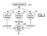
- FIG. 5 a high level flow chart illustrating obtaining a sensor pressure status from the measured pressure is illustrated.
- the pressure status is determined in a similar manner for each of the tires on the vehicle.
- the pressure is measured at the pressure sensor and transmitted to the receiver and is ultimately used in the controller.
- the pressure measured is compared to a low pressure threshold and a low pressure warning is generated if the measured pressure is below the low pressure threshold.
- a high pressure warning is generated.
- block 126 if the measured pressure is below a flat pressure, then a flat pressure warning is generated.
- the pressure status is obtained from blocks 122 , 124 , and 126 .
- the sensor pressure status is a first stage of pressure monitoring according to the present invention.
- a second stage of pressure monitoring is illustrated in a high level flow chart view.
- a low pressure warning status, a high pressure warning status, a flat pressure warning status, and an overall sensor status is used to form a composite warning status.
- the low pressure warning status is determined.
- the high pressure warning status is determined.
- a flat pressure warning status is determined.
- preferably several measurements take place during normal operation to confirm the status.
- Each of the low pressure warning status, high pressure warning status, and flat pressure warning status are combined together to form the composite warning status in block 136 .
- the low pressure warning status, the high pressure warning status, and the flat pressure warning status may have two statuses indicative of a warning state indicating the conditions are not met and a not warning state indicating the conditions are not met.
- Block 138 corresponds to a not low sensor status.
- both the front tire pressure and the rear tire pressure may have different threshold values.
- the spare tire may also have its own threshold values.
- block 140 is performed.
- the low warning status is determined in the second stage as will be described below.
- Block 140 when the warning status is not low and the sensor is equal to or above the threshold for the tire, then the sensor pressure status is not low and the system returns to block 138 .
- block 140 when a low warning status is determined, then block 142 is performed.
- block 142 when the pressure is greater than or equal to the threshold pressure of the associated tire, then block 144 is performed.
- a “not low” warning status is determined as will be further described below.
- block 142 is executed.
- block 138 when a warning status of not low is determined, block 138 is executed.
- Blocks 138 through 144 illustrate a continuous loop in which the sensor readings are monitored and a sensor pressure status and warning status are used to move therethrough.
- FIG. 8 a similar state diagram to that of FIG. 7 is illustrated relative to a high pressure threshold.
- the warning status is not high.
- the pressure of the particular tire exceeds a high pressure threshold.
- block 148 determines a high warning status.
- a high warning status is determined as will be further described below.
- block 146 is again executed.
- block 148 if the high warning status criteria are met, a high warning status is generated and block 150 is executed.
- the thresholds may be offset slightly to provide hysteresis.
- block 150 when the pressure reading drops below a high pressure threshold then block 144 is executed. If subsequent readings are greater than the high pressure threshold then block 150 is again executed. In block 152 when the not high warning status criteria are met, as will be further described below, a not high warning status is generated and block 146 is again executed.
- FIG. 9 a state diagram for determining the presence of a flat tire is illustrated.
- block 156 is executed. Again, the thresholds may be offset slightly to provide hysteresis.
- block 56 if a subsequent pressure reading is greater than the flat threshold, then block 154 is again executed.
- block 156 if the criteria for generating a flat warning status is met, as will be further described below, block 158 is executed.
- block 158 when the pressure reading of a subsequent reading exceeds or is equal to a flat threshold, then block 160 is executed.
- Block 160 determines a not flat warning status in a similar manner to that of block 156 .
- block 160 if the subsequent readings drop below the flat warning threshold, then block 158 is again executed.
- block 160 if the criteria for not flat warning status is met, then block 154 is executed.
- FIGS. 7 , 8 , and 9 are simultaneously performed for each wheel.
- FIG. 10 the results obtained from FIGS. 7 , 8 , and 9 are shown in respective columns. True in the columns refers to that pressure threshold being crossed. Thus, the output pressure status shown in the right hand column is “in range” when each of the pressure thresholds are not met. A flat pressure status refers to the flat pressure threshold being met. A low pressure status is obtained when a low pressure threshold is crossed, and a high pressure status when a high pressure threshold is exceeded.
- blocks 140 and 144 of FIG. 7 are illustrated in further detail.
- the qualification process for either a pressure not low warning status or a low pressure warning status is illustrated.
- the system Upon an initial status reading the system is set to a false low warning status as indicated by arrow 163 and block 162 is executed.
- block 164 On the initial status reading, if a low pressure status is obtained in the first reading, block 164 is executed which immediately generates a low warning status. Thus, no waiting periods or other measurements are necessary from an initial standpoint.
- Loop 165 back to the pressure not low block 162 signifies that the initial value was in range and the status value is not an initial value.
- a warning qualification process is started in block 168 .
- block 162 is executed.
- block 168 if a predetermined number of pressure status signals are low or a certain number of pressure status signals over a fixed time period are low, for example five warning events, block 164 is executed.
- block 164 when a not low pressure status is obtained a qualification timer is initiated in block 170 . If a subsequent low pressure warning is received, then block 164 is again executed.
- block 170 if a low warning qualification timer expires, the low warning status if false or “not low pressure” and block 162 is executed.
- the warning status is initiated as represented by arrow 163 by a wake message received from a spare and the vehicle speed is greater than three miles per hour and the low warning status indicates the tire pressure is not low.
- an initial step represented by arrow 177 is a default state in which the initial status is set to not high.
- block 180 is executed in which the high pressure is qualified.
- the qualification may be a predetermined number of sequential pressure sensor status readings being high or a predetermined number of pressure sensor status readings being high over a predetermined time.
- step 178 is re-executed.
- step 180 if a predetermined of pressure sensor status readings are high, then a high warning status is generated in block 182 .
- a high warning status is generated, if a subsequent pressure status is not high then a qualification timer again starts in block 184 .
- step 184 if a subsequent pressure status is high then step 182 is executed.
- step 184 the not high pressure is qualified before issuing a not high warning status.
- a predetermined number of not high pressure statuses must be received before qualification.
- step 178 is again executed.
- a flat warning status is generated in a similar manner to the low warning status of FIG. 11 .
- the difference between flat warning and low warning is the flat warning is a substantially lower pressure than the flat warning.
- This system also begins when a wake up message is received and the speed is greater than three miles per hour. Other considerations may also initiate the process. The default is illustrated by arrow 191 .
- a flat warning status of true is provided in block 194 .
- Loop 196 resets the initial value flag to false after the initial status value is received.
- a qualification timer is initiated in block 198 .
- block 192 is again executed.
- block 198 if a not flat sensor pressure status is received, block 192 is again executed.
- block 198 if the qualification process has a predetermined number of flat warning events, either consecutively or during a time period, block 194 is executed.
- block 194 if a not flat sensor pressure status is obtained a not flat pressure qualification process is initiated in block 200 .
- block 200 if a subsequent flat warning is received, block 194 is again executed.
- block 200 if a predetermined number of not flat pressure statuses are provided, the flat warning status is not false, then block 192 is again executed.
- the output of the warning status generators of FIGS. 11 , 12 , and 13 generate a composite warning status as illustrated by the following table.
- the composite warning status has an independent flat warning status portion, a high warning status portion, and a low warning status portion.
- the composite warning may also include a sensor status portion to indicate a transmitter fault on behalf of the pressure sensor.
- the tire pressure monitoring system may provide some indication through the indicator such as a displayed word, a series of words, an indicator light or a text message that service or adjustment of the tire pressure may be required.
- step 220 the tires are associated with the vehicle locations.
- the operator fills the tire and thereby increases the pressure therein.
- the pressure sensor circuit preferably transmits a pressure reading when an increase of a predetermined amount is sensed. In the present example, 1.5 psi is used. Thus, when the pressure is at least 1.5 psi the system receives a pressure warning from that tire.
- step 226 the increased pressure reading is compared to a normal range. If the pressure increase still does not provide a pressure reading within the normal range the warning statuses are maintained in step 228 .
- step 226 when the new pressure reading is within the normal range the warnings are automatically reset in step 230 for that particular time.
- the displays and the warning status memory may all be reset.
- step 232 new warning statuses are generated for each of the rolling locations of the vehicle. Also, a new status may also be generated for a spare tire.
- the present invention preferably automatically updates the warning statuses of the system in response to increased tire pressure that indicates replacement of one of the tires with the spare tire.
- each tire is associated with a rolling location in the vehicle.
- the spare tire is associated with the spare tire location.
- Various methods for associating as described above may be used.
- the vehicle operator places the spare tire into a rolling position.
- the spare tire is placed in the rolling tire position with a low tire pressure.
- the present invention does not rely upon proper placement.
- the prior spare tire is awakened when rolling movement is provided. The system recognizes that this tire was a previous spare tire and thus now places the spare tire identification into the memory.
- the previously spare tire is now associated with a rolling location.
- the warning statuses in the warning status memory are reset in step 246 .
- the previous spare may be associated into the non-rolling location in the memory after the warning status is generated or in step 244 as mentioned above.
- new warning statuses are generated for the rolling locations that include the previous spare tire.
- the resetting of the warning statuses in step 246 may include resetting the display on which each of the warning statuses are displayed.
- step 240 is illustrated in more detail.
- the system starts in block 281 when a message expected from a tire is missed by the control system.
- the missed message may, for example, be from a fourth tire in a four tire system that has been replaced with another tire such as a spare.
- the missed message initiates a timer represented by arrow 278 . If a message is received before a predetermined time, and the tire is a rolling tire and the timer is stopped as represented by arrow 280 . When the timer expires and the vehicle speed is indicative of the vehicle moving in block 281 , the tire status is set to a pending spare as represented by block 282 . If the vehicle stops moving the tire status is again set to rolling.
- a pending rolling status block 284 is executed in which the tire status is set as a spare status.
- the tire status is set to spare and a pressure message is received and the vehicle is moving, a counter is initiated and a timer is started as illustrated by arrow 286 . If the timer expires, the count is set to zero as represented by arrow 288 and the spare tire status is maintained. Likewise, if the vehicle is not moving the counter is reset to zero and the timer is stopped as represented by arrow 290 . In this manner the spare tire status is maintained.
- the tire status is set to pending rolling and the count is reset to zero as represented by block 292 .
- the vehicle stops moving the tire status is once again returned to spare status and the functions described above with respect to block 284 are executed.
- the tire status is rolling and the system returns to block 281 .
- the vehicle speed sensor and a timer are used to distinguish the various statuses of the vehicle.
- the system recognizes the spare tire and stores the spare tire identification within the system along with the status. Thereafter, the spare tire becomes recognized as one of the rolling tires and thus the system operates receiving normal updates from each of the tires at the rolling positions. As can be seen at least one tire must be in a pending rolling status and one in a pending spare status for the system to change the status. This indicates the movement of one tire. Also, this system presumes that the identification of the spare is known.
- the tire pressure monitoring system 12 of the present invention is preferably suitable for use with auxiliary tires in auxiliary locations.
- the auxiliary tires may, for example be positioned on a trailer 300 .
- Trailer 300 is illustrated having a plurality of auxiliary positions including trailer tires 14 F, 14 G, 14 H, and 14 I.
- the trailer may also carry spare tires in auxiliary locations such as tire 14 J and 14 K.
- Each of the auxiliary tires includes a respective transmitter 16 F– 16 J and a transmitting antenna 18 F– 18 J.
- the vehicle itself may also have an auxiliary location such as on top of the roof, underneath the vehicle, or attached to the rear bumper.
- the present invention senses the presence of an auxiliary tire associated with the vehicle and programs the auxiliary transmitter's identification into the warning status memory.
- Each of the vehicle transmitters 16 F– 16 J has an associated transmitter identification. The transmitter identifications are programmed into the system so that little chance of erroneous entry is provided.
- indicator 52 is illustrated as an LED display 302 .
- LED display 302 has LEDs 304 A, 304 B, 304 C, and 304 D corresponding to rolling locations of the vehicle.
- an LED 304 E corresponding to the position of the spare tire location is shown.
- an auxiliary LED 304 F is shown.
- LED 304 F corresponds to one or many of the auxiliary locations possible.
- an audible indicator 306 may also be incorporated into display 302 .
- Various other forms of display such as a liquid crystal display, navigation system display, or other types of displays may be incorporated into the system.
- step 310 a plurality of transmissions is received from the transmitters around the vehicle. These transmitters may include transmitters that have not yet been programmed into the vehicle warning status memory. It should be noted that the auxiliary sensors as well as other transmissions from adjacent vehicle transmitters may also be received.
- step 314 the amount of time of a transmission is also monitored. The amount of time may, for example be the cumulative time or the cumulative time over a monitored period.
- step 316 when the vehicle has been in motion for a predetermined amount of time as measured by steps 312 and 314 , step 318 is executed.
- step 318 if more than five sensors have been received for at least a predetermined amount of time, step 320 is executed.
- Step 318 used five sensors to indicate four rolling sensors and one spare tire sensor. However, the number five is used to signify the normal amount of tires typically associated with a vehicle. This number may be increased when vehicles have multiple tires in various locations.
- step 320 an extended mode is entered to indicate that more than the normal amount of tires are associated with the vehicle.
- the pressure transmitter identifications have been transmitted for a predetermined amount of time while the vehicle has been moving and thus these transmitters are most likely associated with the vehicle rather than a nearby vehicle.
- step 322 a learn mode is entered.
- step 324 the auxiliary transmitter identifications are added to the warning status memory.
- the rolling tires, the spare tires, and any auxiliary tire transmitter identification numbers are now associated with the warning status memory.
- warning statuses for all the sensors may be generated as described above.
- a warning status is provided when a tire is over pressure, under pressure, or flat.
- a normal mode is entered in step 328 to indicate to the system that no further identifications need to be programmed into the system.
- step 328 the display is used to display the various warning statuses for each of the tire locations.
- auxiliary tires to the system requires a tire transmitter to be added to the valve stem of any additional auxiliary tires if one is not present. This addition is relatively easy.
- the system may automatically switch from normal mode to extended mode as described above.
- step 318 may be replaced by detection that a trailer has been electrically connected to a trailer socket.
- the buttons 50 above may be used to program in various pressure thresholds in the case that the auxiliary tires have different pressure thresholds for the flat tire, low tire, and high pressure settings.
- step 350 it is determined whether the mini-spare has replaced a rolling tire. If the mini-spare has not replaced the rolling tire then step 350 is repeated.
- the presence of the mini-spare is preferably determined automatically such as in the manner described above. Also, the operator of the vehicle may push a button or otherwise manually enter the presence of the mini-spare into the system.
- the spare tire may provide a special data signal indicating that the tire is a mini-spare rather than a regular spare tire.
- step 351 the speed of the mini-spare is determined.
- the speed of the mini-spare may be determined as a function of the vehicle speed. That is, the vehicle speed may correspond exactly to the speed of the mini-spare.
- step 352 the mini-spare speed is compared to a mini-spare speed threshold.
- the mini-spare speed threshold is typically provided by the manufacturer of the mini-spare. Oftentimes the speed threshold is about 55 miles per hour.
- the mini-spare speed threshold may be programmed at the factory during assembly of the vehicle or may be manually entered into the system.
- a warning signal is generated in step 354 .
- the warning signal may, for example, be an audible signal or a visual signal.
- the audible signal may be provided through a warning buzzer or chime.
- the visual signal may provide a display or LED display.
- the distance may also be determined simultaneously with the speed of step 351 – 354 .
- the distance from replacement is measured as the vehicle travels.
- the distance measured may be activated by the replacement of the spare. That is, the distance may start to be measured when the system receives the mini-spare identification signal.
- the distance may be determined from the time of manually entering the presence of a mini-spare into the system.
- the system may also keep track of the cumulative distance traveled if the spare has been used intermittently.
- the system may also activate the timer noted above. By determining a time signal from the time of reset and measuring the vehicle speed at various times, the distance traveled may be generated according to the formula
- step 360 When in step 360 the mini-spare distance threshold is not exceeded, step 358 is repeated.
- step 362 When the mini-spare threshold is exceeded a distance warning signal is generated in step 362 .
- the distance warning signal may also be stored in the warning status memory.
- a distance and speed warning is displayed in response to the distance and speed warning signal.
- the display may be displayed in a variety of manners set forth above such as on an LCD display, a navigation display, an LED display, warning chimes, or the like.
- the mini-spare takes the place of spare tire 14 e set forth in FIG. 1 .
- the spare tire may also include a pressure sensing circuit such as that used in a typical rolling tire or a regular spare.
- the mini-spare is a lighter and more compact version of the regular spare tire.
- a method for automatically determining the location of each of the tires in the vehicle is illustrated in a state diagrammatic form.
- the vehicle speed is measured and the ignition status is also monitored.
- a low frequency initiator is activated and a counter is set to one and a timer is started.
- a signal from the pressure sensor is expected and thus the system waits for data therefrom.
- Arrow 404 represents that the three second timer has expired before the signal was received. In this situation the counter is incremented and the low frequency initiator is again activated along with the reactivation of the three second timer.
- block 406 when the identification signal from the pressure sensor is the same as one of the identifiers already stored in the status memory, and the sensor status in the sensor signal indicates an initial status, block 406 is executed.
- the initial status is generated in response to the low frequency initiator. That is, normal operating conditions such as reporting pressures do not include the initial status indication.
- the existing identification is confirmed by reactivating the low frequency initiator.
- the count is incremented and a three second timer is started.
- the status of the low frequency initiator is reset to null and step 402 is again executed.
- the transition from block 406 to block 402 indicates the system is confused because two conflicting sensor identifications were received. Upon conflict the system is restarted in block 402 .
- block 406 when no different sensor identification signals are received the low frequency initiator status is existing and the system continues in block 408 described below.
- block 410 when the sensor identification signal is previously unstored in the memory and the sensor status is an initial status, block 410 is executed.
- the low frequency initiator is again activated to confirm the newly-received sensor identification.
- the sensor status is an initial status and the sensor identification is an existing identification and the low frequency initiator status is still trying to confirm, then the count is incremented and the three second timer is started, the low frequency initiator status is reset to null and the low frequency initiator is again activated before the system returns to block 402 .
- block 410 when the three second timer is running the sensor status is in initial state and the sensor identification is confirmed, block 408 is executed as will be described below.
- a pending fault is indicated and the system returns to block 408 in which the above steps 402 through 412 are again performed for each of the plurality of tire locations.
- the statuses of each of the tire locations are held in memory when the ignition is in a run state.
- the system returns to block 400 .
- each of the tire position locations are determined either sequentially or simultaneously to determine the positions relative to the vehicle thereof.
Abstract
Description
| TABLE | ||||
| Flat | Low | High | Composite | |
| Warning | Warning | Warning | Warning | |
| Sensor Status | Status | Status | Status | Status |
| Don't Care | TRUE | Don't Care | Don't Care | Flat |
| Don't Care | False | TRUE | Don't Care | Low |
| Don't Care | False | False | TRUE | High |
| Transmitter Fau | False | False | False | Fault |
| In Range | False | False | False | In Range |
-
- where Di is the distance traveled from the time the mini-spare is started to be used until the ith measurement of vehicle speed, Vi is the ith measurement of vehicle speed, and
ΔT t-1′ - is the amount of time between the ith and (i−1)th measurement of vehicle speed. The distance traveled may also be obtained from odometer readings placed on the communication bus of the vehicle.
- where Di is the distance traveled from the time the mini-spare is started to be used until the ith measurement of vehicle speed, Vi is the ith measurement of vehicle speed, and
Claims (17)
Priority Applications (1)
| Application Number | Priority Date | Filing Date | Title |
|---|---|---|---|
| US10/064,691 US7026922B1 (en) | 2002-08-07 | 2002-08-07 | Method and apparatus for automatically identifying the location of pressure sensors in a tire pressure monitoring system |
Applications Claiming Priority (1)
| Application Number | Priority Date | Filing Date | Title |
|---|---|---|---|
| US10/064,691 US7026922B1 (en) | 2002-08-07 | 2002-08-07 | Method and apparatus for automatically identifying the location of pressure sensors in a tire pressure monitoring system |
Publications (1)
| Publication Number | Publication Date |
|---|---|
| US7026922B1 true US7026922B1 (en) | 2006-04-11 |
Family
ID=36127734
Family Applications (1)
| Application Number | Title | Priority Date | Filing Date |
|---|---|---|---|
| US10/064,691 Expired - Fee Related US7026922B1 (en) | 2002-08-07 | 2002-08-07 | Method and apparatus for automatically identifying the location of pressure sensors in a tire pressure monitoring system |
Country Status (1)
| Country | Link |
|---|---|
| US (1) | US7026922B1 (en) |
Cited By (20)
| Publication number | Priority date | Publication date | Assignee | Title |
|---|---|---|---|---|
| US20050165525A1 (en) * | 2004-01-22 | 2005-07-28 | Shih-Hsiung Li | Parking guidance system for large vehicles |
| US20060259214A1 (en) * | 2005-05-11 | 2006-11-16 | Ford Global Technologies, Llc | Method and apparatus for automatically identifying the location of pressure sensors in a tire pressure monitoring system |
| US20090066487A1 (en) * | 2007-09-08 | 2009-03-12 | Thomas Lee Miller | Status indicator and reminder system for vehicle temporary mobility kit |
| KR100892829B1 (en) | 2007-12-05 | 2009-04-10 | 현대자동차주식회사 | Method for operating auto-running mode in tire pressure monitoring system |
| US20090096599A1 (en) * | 2007-10-15 | 2009-04-16 | Stemco Lp | Identification and Monitoring of Vehicle Sensors |
| DE102009029480A1 (en) | 2008-11-05 | 2010-05-06 | Ford Global Technologies, LLC, Dearborn | Trailer tire pressure monitoring system |
| US20100117817A1 (en) * | 2008-11-12 | 2010-05-13 | Stemco Lp | On-board low-power vehicle condition indicator |
| US20100148949A1 (en) * | 2008-12-12 | 2010-06-17 | Mcquade Thomas Michael | Method and system for associating a tire pressure sensor to a wheel location in an intitiator based tire pressure monitoring system |
| US20100154925A1 (en) * | 2007-08-20 | 2010-06-24 | Ford Global Technologies, Llc. | Cord wrap and power plug receptacle arrangement for inflator |
| US20100156667A1 (en) * | 2008-12-23 | 2010-06-24 | Brian Bennie | Trailer identification system |
| US20100179724A1 (en) * | 2007-06-20 | 2010-07-15 | David Alan Weston | Autolocation of all tire id's on a multi-axle vehicle |
| US20130054079A1 (en) * | 2011-08-24 | 2013-02-28 | Kabushiki Kaisha Tokai Rika Denki Seisakusho | Valve id registration system |
| US20130074591A1 (en) * | 2011-09-23 | 2013-03-28 | Samsung Electro-Mechanics Co., Ltd. | Tire pressure monitoring system (tpms) device |
| US20140032073A1 (en) * | 2011-06-07 | 2014-01-30 | Nissan Motor Co., Ltd. | Parking lock control device for vehicle and control method |
| US8981921B2 (en) | 2007-09-08 | 2015-03-17 | Ford Global Technologies, Llc | Status indicator and reminder system for vehicle temporary mobility kit |
| US9096018B2 (en) | 2007-08-20 | 2015-08-04 | Ford Global Technologies, Llc | Temporary mobility kit with inadvertent flow prevention techniques |
| US9216719B2 (en) | 2011-06-07 | 2015-12-22 | Nissan Motor Co., Ltd. | Parking lock control device for vehicle and control method |
| US9233671B2 (en) | 2011-06-07 | 2016-01-12 | Nissan Motor Co., Ltd. | Parking lock control device for vehicle and control method |
| US20170166020A1 (en) * | 2015-12-10 | 2017-06-15 | Hyundai Motor Company | Tire pressure monitoring system and apparatus and method for controlling the same |
| US10717330B2 (en) * | 2016-11-01 | 2020-07-21 | Continental Reifen Deutschland Gmbh | Method for assigning tyre-sensor modules to a trailer vehicle of an associated utility vehicle combination |
Citations (81)
| Publication number | Priority date | Publication date | Assignee | Title |
|---|---|---|---|---|
| US1948427A (en) | 1932-12-02 | 1934-02-20 | Arnoid H Moecker | Oil mileage indicator |
| US1954133A (en) | 1929-01-14 | 1934-04-10 | Universal Oil Prod Co | Hydrocarbon oil conversion |
| US2274557A (en) | 1940-07-10 | 1942-02-24 | Morgan Raymond | Electric gauge |
| US2578358A (en) | 1947-03-31 | 1951-12-11 | Ernest E Jellison | Signaling device for automobiles |
| US2589623A (en) | 1949-06-13 | 1952-03-18 | Merritt | Mileage service indicator for motor vehicles |
| US3852717A (en) | 1971-11-22 | 1974-12-03 | Nissan Motor | Device for automatically detecting abnormal conditions in vehicle tires |
| US3911855A (en) | 1974-10-07 | 1975-10-14 | Gen Motors Corp | Service card dispenser |
| US3965847A (en) | 1975-04-03 | 1976-06-29 | General Motors Corporation | Service minder odometer |
| US3974477A (en) | 1974-05-09 | 1976-08-10 | Hester Sam R | Pneumatic pressure monitoring system |
| US4051803A (en) | 1976-09-09 | 1977-10-04 | Arnone Charles V | Air leakage indicator device for a spare tire |
| US4316176A (en) | 1979-12-26 | 1982-02-16 | Eaton Corporation | Tire pressure monitor and self check system therefore |
| US4376931A (en) | 1980-02-07 | 1983-03-15 | Meisei Electric Co., Ltd. | System for detecting abnormality in internal pressure of tire |
| US4443785A (en) | 1980-01-15 | 1984-04-17 | Eaton Corporation | Low power put timer circuit and the application thereof within a tire pressure monitor |
| US4494106A (en) | 1981-02-18 | 1985-01-15 | Grathnail Development Company Limited | Pressure monitor |
| US4510484A (en) | 1983-03-28 | 1985-04-09 | Imperial Clevite Inc. | Piezoelectric reed power supply for use in abnormal tire condition warning systems |
| US4574267A (en) | 1982-05-06 | 1986-03-04 | Trw Inc. | Tire pressure warning system |
| US4742476A (en) | 1986-01-27 | 1988-05-03 | General Motors Corporation | Automatic engine oil change indicator system |
| US5061917A (en) | 1988-05-06 | 1991-10-29 | Higgs Nigel H | Electronic warning apparatus |
| US5109213A (en) | 1991-07-05 | 1992-04-28 | Williams John J | Tire pressure monitor |
| US5463374A (en) | 1994-03-10 | 1995-10-31 | Delco Electronics Corporation | Method and apparatus for tire pressure monitoring and for shared keyless entry control |
| US5517853A (en) | 1993-02-11 | 1996-05-21 | Compagnie Generale Des Establissements Michelin-Michelin Et Cie | Process for using signals in a tire monitoring system to determine reinflation |
| US5569848A (en) | 1995-01-06 | 1996-10-29 | Sharp; Everett H. | System, method and apparatus for monitoring tire inflation pressure in a vehicle tire and wheel assembly |
| US5583482A (en) | 1993-06-25 | 1996-12-10 | Compagnie Generale Des Etablissements Michelin-Michelin & Cie | Device for monitoring tires with transmission of electric signals through the wheel disks |
| US5587698A (en) | 1992-02-05 | 1996-12-24 | Genna; Robert A. | Automatic tire pressure control system for a vehicle |
| US5589815A (en) | 1993-11-02 | 1996-12-31 | Honda Giken Kogyo Kabushiki Kaisha | System for determining pneumatic tire pressure for motor vehicle |
| US5600301A (en) | 1993-03-11 | 1997-02-04 | Schrader Automotive Inc. | Remote tire pressure monitoring system employing coded tire identification and radio frequency transmission, and enabling recalibration upon tire rotation or replacement |
| US5602524A (en) | 1992-02-26 | 1997-02-11 | Mock; Markus | Device for monitoring the air-pressure in pneumatic tires fitted on vehicle wheels |
| US5612671A (en) | 1995-12-11 | 1997-03-18 | Delco Electronics Corp. | Method of learning tire pressure transmitter ID |
| US5656993A (en) | 1995-05-08 | 1997-08-12 | Semisystems, Inc. | Vehicle wheel condition monitor and data storage system |
| US5661651A (en) | 1995-03-31 | 1997-08-26 | Prince Corporation | Wireless vehicle parameter monitoring system |
| US5717376A (en) | 1996-09-03 | 1998-02-10 | United Technologies Automotive, Inc. | System for determining failure of remote sensing device |
| US5721528A (en) | 1996-12-23 | 1998-02-24 | Ford Global Technologies, Inc. | Low tire warning system |
| US5741966A (en) | 1993-08-03 | 1998-04-21 | Handfield; Michael | Method and system for monitoring a parameter of a vehicle tire |
| US5790016A (en) * | 1997-01-15 | 1998-08-04 | Algonquin Scientific, Llc | Tire pressure sensing system |
| US5801306A (en) | 1996-03-20 | 1998-09-01 | Compagnie Generale Des Etablissements Michelin - Michelin & Cie | Method of processing pressure measurements in a tire monitoring system |
| US5808190A (en) | 1996-05-09 | 1998-09-15 | Continental Aktienegesellschaft | Air pressure control system |
| US5838229A (en) | 1995-07-18 | 1998-11-17 | Schrader-Bridgeport International, Inc. | Remote tire pressure monitoring system employing coded tire identification and radio frequency transmission and enabling recalibration upon tire rotation or replacement |
| US5853020A (en) | 1995-06-23 | 1998-12-29 | Widner; Ronald D. | Miniature combination valve and pressure transducer and system |
| US5880363A (en) * | 1996-08-09 | 1999-03-09 | Temic Telefunken Microelectronic Gmbh | Process for checking air pressure in vehicle wheel tires |
| US5913240A (en) | 1994-09-30 | 1999-06-15 | Continental Aktiengesellschaft | Method and device for controlling slip and/or for determining the longitudinal force or a flex work-proportional parameter, and vehicle tire therefore |
| US5926087A (en) | 1997-12-22 | 1999-07-20 | Prince Corporation | Visor parameter monitor and display |
| US5939977A (en) | 1996-04-03 | 1999-08-17 | Ssi Technologies, Inc. | Method and apparatus for synchronizing to a data stream for an inductively coupled transponder |
| US5959202A (en) | 1997-01-27 | 1999-09-28 | Sumitomo Electric Industries, Ltd. | Device for determining initial correction factor for correcting rotational velocity of tire |
| US5963128A (en) | 1994-11-22 | 1999-10-05 | Schrader-Bridgeport International, Inc. | Remote tire pressure monitoring system |
| US5965808A (en) | 1995-12-12 | 1999-10-12 | Normann; Norbert | Method of operating tire pressure signalling devices on wheels fitted with pneumatic tires |
| US5969236A (en) | 1996-08-20 | 1999-10-19 | Ngk Insulators, Ltd. | Particle sensor |
| US5990785A (en) | 1998-04-28 | 1999-11-23 | Suda; Raymond A. | Pager vehicle communication apparatus |
| US5999091A (en) | 1996-11-25 | 1999-12-07 | Highwaymaster Communications, Inc. | Trailer communications system |
| US6002327A (en) | 1998-11-04 | 1999-12-14 | Ford Global Technologies, Inc. | Low tire warning system with axle torque signal |
| US6034597A (en) | 1996-08-07 | 2000-03-07 | Ami Doduco Gmbh | Process for evaluating the signals from a tire pressure monitoring system |
| US6043738A (en) | 1998-06-26 | 2000-03-28 | Schrader-Bridgeport International, Inc. | Method and apparatus for identifying remote sending units in a vehicle |
| US6046672A (en) | 1996-07-29 | 2000-04-04 | Pearman; Kevin Patrick Austin | Tire deflation detector |
| US6078252A (en) | 1997-03-28 | 2000-06-20 | Lear Automotive Dearborn, Inc. | Vehicle wireless switching system |
| US6111520A (en) | 1997-04-18 | 2000-08-29 | Georgia Tech Research Corp. | System and method for the wireless sensing of physical properties |
| US6161071A (en) | 1999-03-12 | 2000-12-12 | Navigation Technologies Corporation | Method and system for an in-vehicle computing architecture |
| US6204758B1 (en) | 1999-07-23 | 2001-03-20 | Schrader-Bridgeport International, Inc. | System to automatically determine wheel position for automotive remote tire monitoring system |
| US6218936B1 (en) * | 1998-08-25 | 2001-04-17 | Pacific Industrial Co. Ltd. | Tire air pressure monitoring system |
| US6225895B1 (en) | 1999-05-26 | 2001-05-01 | Floyd E. Bigelow, Jr. | Towed vehicle monitor system |
| US6232875B1 (en) | 2000-06-27 | 2001-05-15 | Trw Inc. | Apparatus and method for controlling a tire condition module of a vehicle tire |
| US6246317B1 (en) | 1998-02-27 | 2001-06-12 | William Pickornik | Target pressure learn strategy for vehicular tire pressure systems |
| US6259361B1 (en) | 1998-07-13 | 2001-07-10 | Prince Corporation | Tire monitoring system |
| US20010008083A1 (en) | 1999-08-16 | 2001-07-19 | Brown Robert Walter | Monitoring pneumatic tire conditions |
| US6271748B1 (en) | 1994-08-31 | 2001-08-07 | Andrew John Derbyshire | Tyre condition monitoring system |
| US6275231B1 (en) | 1997-08-01 | 2001-08-14 | American Calcar Inc. | Centralized control and management system for automobiles |
| US6278379B1 (en) | 1998-04-02 | 2001-08-21 | Georgia Tech Research Corporation | System, method, and sensors for sensing physical properties |
| US6278363B1 (en) | 2000-07-14 | 2001-08-21 | Motorola, Inc | Method and system for monitoring air pressure of tires on a vehicle |
| US6292096B1 (en) | 1999-12-15 | 2001-09-18 | Trw Inc. | Apparatus and method for transmitting data in a tire condition sensing system |
| US6293147B1 (en) | 1999-12-23 | 2001-09-25 | Hunter Engineering Company | Wheel balancer with pressure adjustment |
| US6327570B1 (en) | 1998-11-06 | 2001-12-04 | Dian Stevens | Personal business service system and method |
| US6339736B1 (en) | 2000-03-31 | 2002-01-15 | International Business Machines Corporation | System and method for the distribution of automotive services |
| US6369703B1 (en) | 2000-06-30 | 2002-04-09 | Eaton Corporation | Tire pressure monitor and location identification system |
| US6385511B1 (en) | 2001-01-11 | 2002-05-07 | Sagem Sa | Method and device of processing a signal sensed on board a vehicle from one of its wheels, and corresponding learning method |
| US6448891B2 (en) | 1999-07-12 | 2002-09-10 | Geomat Insights, Llc | Wireless remote tire parameter measurement method and apparatus |
| US6448892B1 (en) | 1999-09-03 | 2002-09-10 | Sagem Sa | Receiver for monitoring vehicle tire pressure and associated transmitter for remote control of other elements of the vehicle |
| US6446502B1 (en) | 1997-08-19 | 2002-09-10 | Beru Aktiengesellschaft | Method for assigning identifiers, present in signals emitted by transmitters in a tire pressure monitoring system, to the wheels where the transmitters are located |
| US6453737B2 (en) | 1999-06-16 | 2002-09-24 | Jorge A. Young | Tire pressure sensory and monitoring method |
| US6463798B2 (en) | 2001-01-17 | 2002-10-15 | Microchip Technology Incorporated | Tire inflation pressure monitoring and location determining method and apparatus |
| US6498967B1 (en) * | 2001-09-10 | 2002-12-24 | The Goodyear Tire & Rubber Company | Tire initiated vehicle control system |
| US6518876B1 (en) | 2000-04-25 | 2003-02-11 | Schrader-Bridgeport International, Inc. | Determination of wheel sensor position using radio frequency detectors in an automotive remote tire monitor system |
| US6612165B2 (en) | 2002-02-04 | 2003-09-02 | Trw Inc. | Tire pressure monitoring system with pressure gauge operating mode for indicating when air pressure within a tire is within a predetermined pressure range |
| US6667687B1 (en) | 2000-11-14 | 2003-12-23 | Trw Inc. | Tire condition sensor communication with duty-cycled, amplified tire-side reception |
-
2002
- 2002-08-07 US US10/064,691 patent/US7026922B1/en not_active Expired - Fee Related
Patent Citations (83)
| Publication number | Priority date | Publication date | Assignee | Title |
|---|---|---|---|---|
| US1954133A (en) | 1929-01-14 | 1934-04-10 | Universal Oil Prod Co | Hydrocarbon oil conversion |
| US1948427A (en) | 1932-12-02 | 1934-02-20 | Arnoid H Moecker | Oil mileage indicator |
| US2274557A (en) | 1940-07-10 | 1942-02-24 | Morgan Raymond | Electric gauge |
| US2578358A (en) | 1947-03-31 | 1951-12-11 | Ernest E Jellison | Signaling device for automobiles |
| US2589623A (en) | 1949-06-13 | 1952-03-18 | Merritt | Mileage service indicator for motor vehicles |
| US3852717A (en) | 1971-11-22 | 1974-12-03 | Nissan Motor | Device for automatically detecting abnormal conditions in vehicle tires |
| US3974477A (en) | 1974-05-09 | 1976-08-10 | Hester Sam R | Pneumatic pressure monitoring system |
| US3911855A (en) | 1974-10-07 | 1975-10-14 | Gen Motors Corp | Service card dispenser |
| US3965847A (en) | 1975-04-03 | 1976-06-29 | General Motors Corporation | Service minder odometer |
| US4051803A (en) | 1976-09-09 | 1977-10-04 | Arnone Charles V | Air leakage indicator device for a spare tire |
| US4316176A (en) | 1979-12-26 | 1982-02-16 | Eaton Corporation | Tire pressure monitor and self check system therefore |
| US4443785A (en) | 1980-01-15 | 1984-04-17 | Eaton Corporation | Low power put timer circuit and the application thereof within a tire pressure monitor |
| US4376931A (en) | 1980-02-07 | 1983-03-15 | Meisei Electric Co., Ltd. | System for detecting abnormality in internal pressure of tire |
| US4494106A (en) | 1981-02-18 | 1985-01-15 | Grathnail Development Company Limited | Pressure monitor |
| US4574267A (en) | 1982-05-06 | 1986-03-04 | Trw Inc. | Tire pressure warning system |
| US4510484A (en) | 1983-03-28 | 1985-04-09 | Imperial Clevite Inc. | Piezoelectric reed power supply for use in abnormal tire condition warning systems |
| US4742476A (en) | 1986-01-27 | 1988-05-03 | General Motors Corporation | Automatic engine oil change indicator system |
| US5061917A (en) | 1988-05-06 | 1991-10-29 | Higgs Nigel H | Electronic warning apparatus |
| US5109213A (en) | 1991-07-05 | 1992-04-28 | Williams John J | Tire pressure monitor |
| US5587698A (en) | 1992-02-05 | 1996-12-24 | Genna; Robert A. | Automatic tire pressure control system for a vehicle |
| US5602524A (en) | 1992-02-26 | 1997-02-11 | Mock; Markus | Device for monitoring the air-pressure in pneumatic tires fitted on vehicle wheels |
| US5517853A (en) | 1993-02-11 | 1996-05-21 | Compagnie Generale Des Establissements Michelin-Michelin Et Cie | Process for using signals in a tire monitoring system to determine reinflation |
| US5600301A (en) | 1993-03-11 | 1997-02-04 | Schrader Automotive Inc. | Remote tire pressure monitoring system employing coded tire identification and radio frequency transmission, and enabling recalibration upon tire rotation or replacement |
| US5583482A (en) | 1993-06-25 | 1996-12-10 | Compagnie Generale Des Etablissements Michelin-Michelin & Cie | Device for monitoring tires with transmission of electric signals through the wheel disks |
| US5741966A (en) | 1993-08-03 | 1998-04-21 | Handfield; Michael | Method and system for monitoring a parameter of a vehicle tire |
| US5589815A (en) | 1993-11-02 | 1996-12-31 | Honda Giken Kogyo Kabushiki Kaisha | System for determining pneumatic tire pressure for motor vehicle |
| US5463374A (en) | 1994-03-10 | 1995-10-31 | Delco Electronics Corporation | Method and apparatus for tire pressure monitoring and for shared keyless entry control |
| US6271748B1 (en) | 1994-08-31 | 2001-08-07 | Andrew John Derbyshire | Tyre condition monitoring system |
| US5913240A (en) | 1994-09-30 | 1999-06-15 | Continental Aktiengesellschaft | Method and device for controlling slip and/or for determining the longitudinal force or a flex work-proportional parameter, and vehicle tire therefore |
| US5963128A (en) | 1994-11-22 | 1999-10-05 | Schrader-Bridgeport International, Inc. | Remote tire pressure monitoring system |
| US5569848A (en) | 1995-01-06 | 1996-10-29 | Sharp; Everett H. | System, method and apparatus for monitoring tire inflation pressure in a vehicle tire and wheel assembly |
| US5661651A (en) | 1995-03-31 | 1997-08-26 | Prince Corporation | Wireless vehicle parameter monitoring system |
| US5656993A (en) | 1995-05-08 | 1997-08-12 | Semisystems, Inc. | Vehicle wheel condition monitor and data storage system |
| US6199575B1 (en) | 1995-06-23 | 2001-03-13 | Ronald D. Widner | Miniature combination valve and pressure transducer system |
| US5853020A (en) | 1995-06-23 | 1998-12-29 | Widner; Ronald D. | Miniature combination valve and pressure transducer and system |
| US5838229A (en) | 1995-07-18 | 1998-11-17 | Schrader-Bridgeport International, Inc. | Remote tire pressure monitoring system employing coded tire identification and radio frequency transmission and enabling recalibration upon tire rotation or replacement |
| US5612671A (en) | 1995-12-11 | 1997-03-18 | Delco Electronics Corp. | Method of learning tire pressure transmitter ID |
| US5965808A (en) | 1995-12-12 | 1999-10-12 | Normann; Norbert | Method of operating tire pressure signalling devices on wheels fitted with pneumatic tires |
| US5801306A (en) | 1996-03-20 | 1998-09-01 | Compagnie Generale Des Etablissements Michelin - Michelin & Cie | Method of processing pressure measurements in a tire monitoring system |
| US5939977A (en) | 1996-04-03 | 1999-08-17 | Ssi Technologies, Inc. | Method and apparatus for synchronizing to a data stream for an inductively coupled transponder |
| US5808190A (en) | 1996-05-09 | 1998-09-15 | Continental Aktienegesellschaft | Air pressure control system |
| US6046672A (en) | 1996-07-29 | 2000-04-04 | Pearman; Kevin Patrick Austin | Tire deflation detector |
| US6034597A (en) | 1996-08-07 | 2000-03-07 | Ami Doduco Gmbh | Process for evaluating the signals from a tire pressure monitoring system |
| US5880363A (en) * | 1996-08-09 | 1999-03-09 | Temic Telefunken Microelectronic Gmbh | Process for checking air pressure in vehicle wheel tires |
| US5969236A (en) | 1996-08-20 | 1999-10-19 | Ngk Insulators, Ltd. | Particle sensor |
| US5717376A (en) | 1996-09-03 | 1998-02-10 | United Technologies Automotive, Inc. | System for determining failure of remote sensing device |
| US5999091A (en) | 1996-11-25 | 1999-12-07 | Highwaymaster Communications, Inc. | Trailer communications system |
| US5721528A (en) | 1996-12-23 | 1998-02-24 | Ford Global Technologies, Inc. | Low tire warning system |
| US5790016A (en) * | 1997-01-15 | 1998-08-04 | Algonquin Scientific, Llc | Tire pressure sensing system |
| US5959202A (en) | 1997-01-27 | 1999-09-28 | Sumitomo Electric Industries, Ltd. | Device for determining initial correction factor for correcting rotational velocity of tire |
| US6078252A (en) | 1997-03-28 | 2000-06-20 | Lear Automotive Dearborn, Inc. | Vehicle wireless switching system |
| US6111520A (en) | 1997-04-18 | 2000-08-29 | Georgia Tech Research Corp. | System and method for the wireless sensing of physical properties |
| US20020008718A1 (en) | 1997-08-01 | 2002-01-24 | American Calcar Inc. | Centralized control and management system for automobiles |
| US6275231B1 (en) | 1997-08-01 | 2001-08-14 | American Calcar Inc. | Centralized control and management system for automobiles |
| US6446502B1 (en) | 1997-08-19 | 2002-09-10 | Beru Aktiengesellschaft | Method for assigning identifiers, present in signals emitted by transmitters in a tire pressure monitoring system, to the wheels where the transmitters are located |
| US5926087A (en) | 1997-12-22 | 1999-07-20 | Prince Corporation | Visor parameter monitor and display |
| US6246317B1 (en) | 1998-02-27 | 2001-06-12 | William Pickornik | Target pressure learn strategy for vehicular tire pressure systems |
| US6278379B1 (en) | 1998-04-02 | 2001-08-21 | Georgia Tech Research Corporation | System, method, and sensors for sensing physical properties |
| US5990785A (en) | 1998-04-28 | 1999-11-23 | Suda; Raymond A. | Pager vehicle communication apparatus |
| US6043738A (en) | 1998-06-26 | 2000-03-28 | Schrader-Bridgeport International, Inc. | Method and apparatus for identifying remote sending units in a vehicle |
| US6259361B1 (en) | 1998-07-13 | 2001-07-10 | Prince Corporation | Tire monitoring system |
| US6218936B1 (en) * | 1998-08-25 | 2001-04-17 | Pacific Industrial Co. Ltd. | Tire air pressure monitoring system |
| US6002327A (en) | 1998-11-04 | 1999-12-14 | Ford Global Technologies, Inc. | Low tire warning system with axle torque signal |
| US6327570B1 (en) | 1998-11-06 | 2001-12-04 | Dian Stevens | Personal business service system and method |
| US6161071A (en) | 1999-03-12 | 2000-12-12 | Navigation Technologies Corporation | Method and system for an in-vehicle computing architecture |
| US6225895B1 (en) | 1999-05-26 | 2001-05-01 | Floyd E. Bigelow, Jr. | Towed vehicle monitor system |
| US6453737B2 (en) | 1999-06-16 | 2002-09-24 | Jorge A. Young | Tire pressure sensory and monitoring method |
| US6448891B2 (en) | 1999-07-12 | 2002-09-10 | Geomat Insights, Llc | Wireless remote tire parameter measurement method and apparatus |
| US6204758B1 (en) | 1999-07-23 | 2001-03-20 | Schrader-Bridgeport International, Inc. | System to automatically determine wheel position for automotive remote tire monitoring system |
| US20010008083A1 (en) | 1999-08-16 | 2001-07-19 | Brown Robert Walter | Monitoring pneumatic tire conditions |
| US6448892B1 (en) | 1999-09-03 | 2002-09-10 | Sagem Sa | Receiver for monitoring vehicle tire pressure and associated transmitter for remote control of other elements of the vehicle |
| US6292096B1 (en) | 1999-12-15 | 2001-09-18 | Trw Inc. | Apparatus and method for transmitting data in a tire condition sensing system |
| US6293147B1 (en) | 1999-12-23 | 2001-09-25 | Hunter Engineering Company | Wheel balancer with pressure adjustment |
| US6339736B1 (en) | 2000-03-31 | 2002-01-15 | International Business Machines Corporation | System and method for the distribution of automotive services |
| US6518876B1 (en) | 2000-04-25 | 2003-02-11 | Schrader-Bridgeport International, Inc. | Determination of wheel sensor position using radio frequency detectors in an automotive remote tire monitor system |
| US6232875B1 (en) | 2000-06-27 | 2001-05-15 | Trw Inc. | Apparatus and method for controlling a tire condition module of a vehicle tire |
| US6369703B1 (en) | 2000-06-30 | 2002-04-09 | Eaton Corporation | Tire pressure monitor and location identification system |
| US6278363B1 (en) | 2000-07-14 | 2001-08-21 | Motorola, Inc | Method and system for monitoring air pressure of tires on a vehicle |
| US6667687B1 (en) | 2000-11-14 | 2003-12-23 | Trw Inc. | Tire condition sensor communication with duty-cycled, amplified tire-side reception |
| US6385511B1 (en) | 2001-01-11 | 2002-05-07 | Sagem Sa | Method and device of processing a signal sensed on board a vehicle from one of its wheels, and corresponding learning method |
| US6463798B2 (en) | 2001-01-17 | 2002-10-15 | Microchip Technology Incorporated | Tire inflation pressure monitoring and location determining method and apparatus |
| US6498967B1 (en) * | 2001-09-10 | 2002-12-24 | The Goodyear Tire & Rubber Company | Tire initiated vehicle control system |
| US6612165B2 (en) | 2002-02-04 | 2003-09-02 | Trw Inc. | Tire pressure monitoring system with pressure gauge operating mode for indicating when air pressure within a tire is within a predetermined pressure range |
Cited By (41)
| Publication number | Priority date | Publication date | Assignee | Title |
|---|---|---|---|---|
| US20050165525A1 (en) * | 2004-01-22 | 2005-07-28 | Shih-Hsiung Li | Parking guidance system for large vehicles |
| US7225070B2 (en) * | 2004-01-22 | 2007-05-29 | Shih-Hsiung Li | Parking guidance system for large vehicles |
| US20060259214A1 (en) * | 2005-05-11 | 2006-11-16 | Ford Global Technologies, Llc | Method and apparatus for automatically identifying the location of pressure sensors in a tire pressure monitoring system |
| US7369043B2 (en) * | 2005-05-11 | 2008-05-06 | Ford Global Technologies, Llc | Method and apparatus for automatically identifying the location of pressure sensors in a tire pressure monitoring system |
| US8463491B2 (en) * | 2007-06-20 | 2013-06-11 | Compagnie Generale Des Etablissements Michelin | Autolocation of all tire ID's on a multi-axle vehicle |
| US20100179724A1 (en) * | 2007-06-20 | 2010-07-15 | David Alan Weston | Autolocation of all tire id's on a multi-axle vehicle |
| US8517760B2 (en) | 2007-08-20 | 2013-08-27 | Ford Global Technologies, Llc | Cord wrap and power plug receptacle arrangement for inflator |
| US20100154925A1 (en) * | 2007-08-20 | 2010-06-24 | Ford Global Technologies, Llc. | Cord wrap and power plug receptacle arrangement for inflator |
| US9096018B2 (en) | 2007-08-20 | 2015-08-04 | Ford Global Technologies, Llc | Temporary mobility kit with inadvertent flow prevention techniques |
| US8932076B2 (en) | 2007-08-20 | 2015-01-13 | Ford Global Technologies, Llc | Cord wrap and power plug receptacle arrangement for inflator |
| US20110094620A9 (en) * | 2007-08-20 | 2011-04-28 | Ford Global Technologies, Llc. | Cord wrap and power plug receptacle arrangement for inflator |
| US8115615B2 (en) | 2007-09-08 | 2012-02-14 | Ford Global Technologies | Status indicator and reminder system for vehicle temporary mobility kit |
| US20090066487A1 (en) * | 2007-09-08 | 2009-03-12 | Thomas Lee Miller | Status indicator and reminder system for vehicle temporary mobility kit |
| US8981921B2 (en) | 2007-09-08 | 2015-03-17 | Ford Global Technologies, Llc | Status indicator and reminder system for vehicle temporary mobility kit |
| US20090096599A1 (en) * | 2007-10-15 | 2009-04-16 | Stemco Lp | Identification and Monitoring of Vehicle Sensors |
| KR100892829B1 (en) | 2007-12-05 | 2009-04-10 | 현대자동차주식회사 | Method for operating auto-running mode in tire pressure monitoring system |
| DE102009029480A1 (en) | 2008-11-05 | 2010-05-06 | Ford Global Technologies, LLC, Dearborn | Trailer tire pressure monitoring system |
| DE102009029480B4 (en) * | 2008-11-05 | 2017-10-19 | Ford Global Technologies, Llc | Trailer tire pressure monitoring system |
| US9090206B2 (en) * | 2008-11-12 | 2015-07-28 | Stemco Lp | On-board low-power vehicle condition indicator |
| US9545876B2 (en) | 2008-11-12 | 2017-01-17 | Stemco Lp | On-board low-power vehicle condition indicator |
| US20100117817A1 (en) * | 2008-11-12 | 2010-05-13 | Stemco Lp | On-board low-power vehicle condition indicator |
| US7916010B2 (en) * | 2008-12-12 | 2011-03-29 | Ford Global Technologies | Method and system for associating a tire pressure sensor to a wheel location in an intitiator based tire pressure monitoring system |
| US20100148949A1 (en) * | 2008-12-12 | 2010-06-17 | Mcquade Thomas Michael | Method and system for associating a tire pressure sensor to a wheel location in an intitiator based tire pressure monitoring system |
| US20100156667A1 (en) * | 2008-12-23 | 2010-06-24 | Brian Bennie | Trailer identification system |
| CN101758752B (en) * | 2008-12-23 | 2014-04-23 | 福特全球技术公司 | Trailer identification system |
| DE102009044669B4 (en) * | 2008-12-23 | 2020-10-22 | Ford Global Technologies, Llc | Trailer identification system |
| US8068019B2 (en) * | 2008-12-23 | 2011-11-29 | Ford Global Technologies | Trailer identification system |
| DE102009044669A1 (en) | 2008-12-23 | 2010-07-01 | Ford Global Technologies, LLC, Dearborn | Trailer identification system |
| CN101758752A (en) * | 2008-12-23 | 2010-06-30 | 福特全球技术公司 | Trailer identification system |
| US9216719B2 (en) | 2011-06-07 | 2015-12-22 | Nissan Motor Co., Ltd. | Parking lock control device for vehicle and control method |
| US9096197B2 (en) * | 2011-06-07 | 2015-08-04 | Nissan Motor Co., Ltd. | Parking lock control device for vehicle and control method |
| US9233671B2 (en) | 2011-06-07 | 2016-01-12 | Nissan Motor Co., Ltd. | Parking lock control device for vehicle and control method |
| US20140032073A1 (en) * | 2011-06-07 | 2014-01-30 | Nissan Motor Co., Ltd. | Parking lock control device for vehicle and control method |
| US20130054079A1 (en) * | 2011-08-24 | 2013-02-28 | Kabushiki Kaisha Tokai Rika Denki Seisakusho | Valve id registration system |
| US20130074591A1 (en) * | 2011-09-23 | 2013-03-28 | Samsung Electro-Mechanics Co., Ltd. | Tire pressure monitoring system (tpms) device |
| US20170166020A1 (en) * | 2015-12-10 | 2017-06-15 | Hyundai Motor Company | Tire pressure monitoring system and apparatus and method for controlling the same |
| CN106864182A (en) * | 2015-12-10 | 2017-06-20 | 现代自动车株式会社 | tire pressure monitoring system and its control device and method |
| US9789740B2 (en) * | 2015-12-10 | 2017-10-17 | Hyundai Motor Company | Tire pressure monitoring system and apparatus and method for controlling the same |
| CN106864182B (en) * | 2015-12-10 | 2019-12-31 | 现代自动车株式会社 | Tire pressure monitoring system and control device and method thereof |
| US10717330B2 (en) * | 2016-11-01 | 2020-07-21 | Continental Reifen Deutschland Gmbh | Method for assigning tyre-sensor modules to a trailer vehicle of an associated utility vehicle combination |
| US11173757B2 (en) * | 2016-11-01 | 2021-11-16 | Continental Reifen Deutschland Gmbh | Method for assigning tyre-sensor modules to a trailer vehicle of an associated utility vehicle combination |
Similar Documents
| Publication | Publication Date | Title |
|---|---|---|
| US6982636B1 (en) | Method and system for mitigating false alarms in a tire pressure monitoring system for an automotive vehicle | |
| US20050200464A1 (en) | Method and system of notifying of use of a tire in a tire pressure monitoring system for an automotive vehicle | |
| US7092804B2 (en) | Method and apparatus for providing refill or bleed alerts in a tire pressure monitoring system | |
| US6784794B1 (en) | Method and apparatus for reminding the vehicle operator to refill the spare tire in a tire pressure monitoring system | |
| US6771169B1 (en) | Tire pressure monitoring system with a signal initiator | |
| US6750762B1 (en) | Method and system for resetting tire pressure monitoring system for an automotive vehicle | |
| US7026922B1 (en) | Method and apparatus for automatically identifying the location of pressure sensors in a tire pressure monitoring system | |
| US20060010961A1 (en) | Method and apparatus for detecting leakage rate in a tire pressure monitoring system | |
| US6985076B1 (en) | Method and system for detecting the presence of a spare replacement in a tire pressure monitoring system for an automotive vehicle | |
| US7369043B2 (en) | Method and apparatus for automatically identifying the location of pressure sensors in a tire pressure monitoring system | |
| US7271709B2 (en) | Robust method and system for the automatic detection of a detached remote tire pressure sensor of a tire pressure monitoring system | |
| US7570157B2 (en) | Method and apparatus for adjusting the pressure sensor measurement range in a tire pressure monitoring system | |
| US7737835B2 (en) | Hand held tire pressure monitoring system | |
| US7224269B2 (en) | Method and system for resetting tire pressure monitoring system for an automotive vehicle | |
| US7916010B2 (en) | Method and system for associating a tire pressure sensor to a wheel location in an intitiator based tire pressure monitoring system | |
| US8854200B2 (en) | TPMS tire fill detection mode to ensure accurate tire filling | |
| JP4213580B2 (en) | System and method for monitoring automobile tire pressure | |
| US6850155B1 (en) | Method and system of notifying of overuse of a mini-spare tire in a tire pressure monitoring system for an automotive vehicle | |
| US8674821B2 (en) | Tire pressure monitoring apparatus | |
| US20100271189A1 (en) | Method for configuring and monitoring a trailer in tow using an integrated trailer brake controller | |
| US8514062B2 (en) | Method for learning and setting warm placard pressure threshold for a direct tire pressure monitoring system | |
| US7330104B2 (en) | Tire inflation pressure monitoring device | |
| US6900725B1 (en) | Method and system for automatically extending a tire pressure monitoring system for an automotive vehicle to include auxiliary tires | |
| JP2019026218A (en) | Tire air pressure monitoring system | |
| US7705717B2 (en) | Method and apparatus for receiving signals from a sensor into a tire pressure monitoring system |
Legal Events
| Date | Code | Title | Description |
|---|---|---|---|
| AS | Assignment |
Owner name: FORD MOTOR COMPANY, MICHIGAN Free format text: ASSIGNMENT OF ASSIGNORS INTEREST;ASSIGNORS:TALUKDER, MONIRUL HUQ;BROMBACH, RONALD PATRICK;MCQUADE, THOMAS MICHAEL;REEL/FRAME:012961/0182 Effective date: 20020606 Owner name: FORD GLOBAL TECHNOLOGIES, INC., MICHIGAN Free format text: ASSIGNMENT OF ASSIGNORS INTEREST;ASSIGNOR:FORD MOTOR COMPANY;REEL/FRAME:012961/0184 Effective date: 20020806 |
|
| AS | Assignment |
Owner name: FORD GLOBAL TECHNOLOGIES, LLC, MICHIGAN Free format text: MERGER;ASSIGNOR:FORD GLOBAL TECHNOLOGIES, INC.;REEL/FRAME:013987/0838 Effective date: 20030301 Owner name: FORD GLOBAL TECHNOLOGIES, LLC,MICHIGAN Free format text: MERGER;ASSIGNOR:FORD GLOBAL TECHNOLOGIES, INC.;REEL/FRAME:013987/0838 Effective date: 20030301 |
|
| FPAY | Fee payment |
Year of fee payment: 4 |
|
| FPAY | Fee payment |
Year of fee payment: 8 |
|
| FEPP | Fee payment procedure |
Free format text: MAINTENANCE FEE REMINDER MAILED (ORIGINAL EVENT CODE: REM.) |
|
| LAPS | Lapse for failure to pay maintenance fees |
Free format text: PATENT EXPIRED FOR FAILURE TO PAY MAINTENANCE FEES (ORIGINAL EVENT CODE: EXP.) |
|
| STCH | Information on status: patent discontinuation |
Free format text: PATENT EXPIRED DUE TO NONPAYMENT OF MAINTENANCE FEES UNDER 37 CFR 1.362 |
|
| FP | Lapsed due to failure to pay maintenance fee |
Effective date: 20180411 |