US7036994B2 - Bezel for fiber optic components - Google Patents
Bezel for fiber optic components Download PDFInfo
- Publication number
- US7036994B2 US7036994B2 US10/775,682 US77568204A US7036994B2 US 7036994 B2 US7036994 B2 US 7036994B2 US 77568204 A US77568204 A US 77568204A US 7036994 B2 US7036994 B2 US 7036994B2
- Authority
- US
- United States
- Prior art keywords
- bezel
- optical coupler
- housing
- panel
- optical
- Prior art date
- Legal status (The legal status is an assumption and is not a legal conclusion. Google has not performed a legal analysis and makes no representation as to the accuracy of the status listed.)
- Expired - Lifetime
Links
- 239000000835 fiber Substances 0.000 title description 4
- 238000004891 communication Methods 0.000 claims abstract description 38
- 230000003287 optical effect Effects 0.000 claims description 78
- 238000000034 method Methods 0.000 claims description 8
- 230000008878 coupling Effects 0.000 claims description 5
- 238000010168 coupling process Methods 0.000 claims description 5
- 238000005859 coupling reaction Methods 0.000 claims description 5
- 238000003780 insertion Methods 0.000 abstract description 3
- 230000037431 insertion Effects 0.000 abstract description 3
- 239000013307 optical fiber Substances 0.000 description 5
- 230000033001 locomotion Effects 0.000 description 2
- 230000002093 peripheral effect Effects 0.000 description 2
- 230000005540 biological transmission Effects 0.000 description 1
- 230000006835 compression Effects 0.000 description 1
- 238000007906 compression Methods 0.000 description 1
- 230000003247 decreasing effect Effects 0.000 description 1
- 238000001746 injection moulding Methods 0.000 description 1
- 239000000463 material Substances 0.000 description 1
- 239000002184 metal Substances 0.000 description 1
Images


Classifications
-
- G—PHYSICS
- G02—OPTICS
- G02B—OPTICAL ELEMENTS, SYSTEMS OR APPARATUS
- G02B6/00—Light guides; Structural details of arrangements comprising light guides and other optical elements, e.g. couplings
- G02B6/24—Coupling light guides
- G02B6/26—Optical coupling means
- G02B6/264—Optical coupling means with optical elements between opposed fibre ends which perform a function other than beam splitting
- G02B6/266—Optical coupling means with optical elements between opposed fibre ends which perform a function other than beam splitting the optical element being an attenuator
-
- G—PHYSICS
- G02—OPTICS
- G02B—OPTICAL ELEMENTS, SYSTEMS OR APPARATUS
- G02B6/00—Light guides; Structural details of arrangements comprising light guides and other optical elements, e.g. couplings
- G02B6/24—Coupling light guides
- G02B6/36—Mechanical coupling means
- G02B6/38—Mechanical coupling means having fibre to fibre mating means
- G02B6/3807—Dismountable connectors, i.e. comprising plugs
- G02B6/381—Dismountable connectors, i.e. comprising plugs of the ferrule type, e.g. fibre ends embedded in ferrules, connecting a pair of fibres
- G02B6/3825—Dismountable connectors, i.e. comprising plugs of the ferrule type, e.g. fibre ends embedded in ferrules, connecting a pair of fibres with an intermediate part, e.g. adapter, receptacle, linking two plugs
-
- G—PHYSICS
- G02—OPTICS
- G02B—OPTICAL ELEMENTS, SYSTEMS OR APPARATUS
- G02B6/00—Light guides; Structural details of arrangements comprising light guides and other optical elements, e.g. couplings
- G02B6/24—Coupling light guides
- G02B6/36—Mechanical coupling means
- G02B6/38—Mechanical coupling means having fibre to fibre mating means
- G02B6/3807—Dismountable connectors, i.e. comprising plugs
- G02B6/3897—Connectors fixed to housings, casing, frames or circuit boards
-
- G—PHYSICS
- G02—OPTICS
- G02B—OPTICAL ELEMENTS, SYSTEMS OR APPARATUS
- G02B6/00—Light guides; Structural details of arrangements comprising light guides and other optical elements, e.g. couplings
- G02B6/24—Coupling light guides
- G02B6/36—Mechanical coupling means
- G02B6/38—Mechanical coupling means having fibre to fibre mating means
- G02B6/3807—Dismountable connectors, i.e. comprising plugs
- G02B6/3833—Details of mounting fibres in ferrules; Assembly methods; Manufacture
- G02B6/3847—Details of mounting fibres in ferrules; Assembly methods; Manufacture with means preventing fibre end damage, e.g. recessed fibre surfaces
- G02B6/3849—Details of mounting fibres in ferrules; Assembly methods; Manufacture with means preventing fibre end damage, e.g. recessed fibre surfaces using mechanical protective elements, e.g. caps, hoods, sealing membranes
Definitions
- the present invention relates to a bezel for connection of optical components to an optical coupler. More particularly, the present invention relates to a bezel for connecting an optical attenuator to an optical coupler.
- Connectors for optical fiber transmission systems are known in the art. Often times it becomes necessary to arrange a plurality of optical fiber connectors in a panel to facilitate multifiber connections. Desirably, devices for holding connectors are mounted in the panel but the connectors themselves are not connected to incoming or outgoing fiber paths until needed to provide service. Commonly used devices which are used to accommodate interconnections are referred to as couplings.
- a very much used connector for terminating and connecting two optical fibers is one which is referred to as an SC connector.
- An SC connector is connected to another SC connector from a module through an SC coupling by linear motion only.
- an attenuator is attached to an SC optical coupler which is attached to a communication module within a control panel; attenuators are very often not included on an optical communication module until a connection is required. This is because depending upon the connection, a different strength optical signal may be required. At the time a connection is required, the panel is opened, and the module containing the SC optical coupler is removed so that an appropriate attenuator may be connected.
- the present invention addresses the above concern and presents a new and novel device for facilitating the connection of an external optical component to a panel. Moreover, the present invention lends itself to connection of an attenuation device to an optical coupler without disrupting an optical module.
- a bezel for facilitating the connection of an optical connector between an optical couple positioned on a module within a panel.
- the bezel includes a housing, a first end for insertion into the panel, an interior portion positioned within the housing for positioning of an optical coupler and a second end having a removable cover concealing an opening.
- the opening exposes an end of the optical coupler positioned within the interior of the bezel for connection to the external device.
- the above described bezel may be used in conjunction with a fiber optical connection panel which includes a communication module including a fiber optical connector for making a connection with an external optical device, and connection surface adjacent the module having an opening corresponding to the connector.
- the bezel according to the present invention is positioned within the opening and facilitates the optical connection between the connector and the external device.
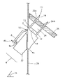
- FIG. 1 is a perspective view of a bezel for connection of optical components according to the present invention.
- FIG. 2 is a side sectional view of the bezel according to the present invention.
- a bezel 1 for facilitating connection of an attenuator 22 to an optical coupler 24 includes a housing 2 , an end 6 for being received in a corresponding receiving area in an optical communication module within an opening in a panel housing optical fiber connections and the like.
- the housing 2 is a body that has a first peripheral end, at least one edge 2 ′ of which engages with the optical coupler 24 at a corresponding edge or retaining tab 18 of the optical coupler 24 extending from a body portion of the optical coupler 24 (for convenience, only one edge 2 ′ and one tab 18 are shown in the drawings).
- the bezel may be manufactured from a variety of materials including metal and plastic, but is preferably made from plastic, and is preferably manufactured by injection molding.
- the bezel 1 also includes an end 4 having a hinged cover 8 , which conceals an opening exposing an end of an optical coupler 24 positioned in an interior portion within the bezel housing.
- the cover 8 abuts edges of the housing 2 forming a second peripheral end of the body of housing 2 , when the cover 8 is in a closed position, and the housing 2 has at least one guiding member (structural abutment) 20 disposed along an interior wall of the housing 2 , for guiding an external device, such as the attenuator 22 , within the interior of the housing 2 .
- guiding member 20 For convenience, only a single guiding member 20 is shown in the drawings, although there may be a guiding member 20 disposed along both opposing interior walls of the housing 2 .
- the hinged portion 10 of the cover may be integral with the housing 2 , or it may include an actual hinge, a half of which is included on the cover and the remaining half being positioned on an upper portion of the end 4 of the bezel.
- the cover may also include locking tabs 8 a .
- the tabs 8 a include two halves 8 a 1 and 8 a 2 with ends having inclined surfaces that enable easy insertion into a corresponding opening 4 a positioned adjacent end 4 of the bezel housing 2 .
- the two halves of the tabs 8 a compress together. A force generated by the compression of the halves is placed on the sides of the openings 4 a , allowing the cover to remain in a closed position.
- the cover is easily opened by applying an outward force on lifting tab 8 b .
- the outward force overcomes a frictional force created between each half of the locking tabs and the respective wall of the opening 4 a , thereby allowing the cover to open and expose the interior of the bezel housing.
- Adjacent end 6 of the bezel are several locking cams 11 positioned on the end of corresponding finger projections (projecting members) 12 .
- Each projection 12 includes an end having an inclined portion 14 ending in a shoulder portion 14 ′, wherein the inclined portion 14 and shoulder portion 14 ′ of each projection 12 form a respective cam surface of the corresponding cam 11 .
- the cams 11 are received in corresponding slots on a module within the panel, and lock thereto.
- the slots in the module surround an optical connector for connection to the coupler of the bezel.
- the cams 11 restrain the optical coupler in the bezel from linear movement away from optical connector of the optical module and also prevent the bezel from being pulled away from the panel, or dislodge in any way.
- the body of the housing 2 and the projections 12 define, in combination, a volume extending from the second of the projections 12 .
- the volume can receive at least a portion of each of the optical coupler 24 and attenuator 22 therein.
- FIG. 2 illustrates the bezel according to the present invention as assembled with an optical module 26 inside a panel 28 .
- the locking cams 11 are received by corresponding slots 26 a and 26 b which allow the locking cams 11 to pass through and lock on the other side.
- the slots are positioned away from one another in the vertical direction as seen in FIG. 2 so that the distance between the inside walls of a pair of adjacent slots, 26 a and 26 b , is equal to the distance between the two corresponding projecting fingers 12 of the bezel.
- the slots are also formed so that the respective cam can easily fit through and lock on the other side.
- the front 4 of the bezel may snap into a cutout in the front panel of the optical connection box.
- the cover 8 is opened by pulling back on tab 8 b , exposing the optical coupler.
- the external optical component may then be connected to the exposed end of the optical coupler to complete the communication connection.
- This system is especially advantageous in connecting an attenuator to the optical module.
Abstract
Description
Claims (27)
Priority Applications (4)
| Application Number | Priority Date | Filing Date | Title |
|---|---|---|---|
| US10/775,682 US7036994B2 (en) | 2000-07-28 | 2004-02-10 | Bezel for fiber optic components |
| US11/378,348 US7153032B2 (en) | 2000-07-28 | 2006-03-20 | Bezel for fiber optic components |
| US11/584,661 US7237964B2 (en) | 2000-07-28 | 2006-10-23 | Bezel for fiber optic components |
| US11/747,986 US7585115B2 (en) | 2000-07-28 | 2007-05-14 | Bezel for fiber optic components |
Applications Claiming Priority (2)
| Application Number | Priority Date | Filing Date | Title |
|---|---|---|---|
| US09/628,348 US6695485B1 (en) | 2000-07-28 | 2000-07-28 | Bezel for fiber optic components |
| US10/775,682 US7036994B2 (en) | 2000-07-28 | 2004-02-10 | Bezel for fiber optic components |
Related Parent Applications (1)
| Application Number | Title | Priority Date | Filing Date |
|---|---|---|---|
| US09/628,348 Continuation US6695485B1 (en) | 2000-07-28 | 2000-07-28 | Bezel for fiber optic components |
Related Child Applications (1)
| Application Number | Title | Priority Date | Filing Date |
|---|---|---|---|
| US11/378,348 Continuation US7153032B2 (en) | 2000-07-28 | 2006-03-20 | Bezel for fiber optic components |
Publications (2)
| Publication Number | Publication Date |
|---|---|
| US20040161202A1 US20040161202A1 (en) | 2004-08-19 |
| US7036994B2 true US7036994B2 (en) | 2006-05-02 |
Family
ID=31496200
Family Applications (5)
| Application Number | Title | Priority Date | Filing Date |
|---|---|---|---|
| US09/628,348 Expired - Fee Related US6695485B1 (en) | 2000-07-28 | 2000-07-28 | Bezel for fiber optic components |
| US10/775,682 Expired - Lifetime US7036994B2 (en) | 2000-07-28 | 2004-02-10 | Bezel for fiber optic components |
| US11/378,348 Expired - Fee Related US7153032B2 (en) | 2000-07-28 | 2006-03-20 | Bezel for fiber optic components |
| US11/584,661 Expired - Fee Related US7237964B2 (en) | 2000-07-28 | 2006-10-23 | Bezel for fiber optic components |
| US11/747,986 Expired - Lifetime US7585115B2 (en) | 2000-07-28 | 2007-05-14 | Bezel for fiber optic components |
Family Applications Before (1)
| Application Number | Title | Priority Date | Filing Date |
|---|---|---|---|
| US09/628,348 Expired - Fee Related US6695485B1 (en) | 2000-07-28 | 2000-07-28 | Bezel for fiber optic components |
Family Applications After (3)
| Application Number | Title | Priority Date | Filing Date |
|---|---|---|---|
| US11/378,348 Expired - Fee Related US7153032B2 (en) | 2000-07-28 | 2006-03-20 | Bezel for fiber optic components |
| US11/584,661 Expired - Fee Related US7237964B2 (en) | 2000-07-28 | 2006-10-23 | Bezel for fiber optic components |
| US11/747,986 Expired - Lifetime US7585115B2 (en) | 2000-07-28 | 2007-05-14 | Bezel for fiber optic components |
Country Status (1)
| Country | Link |
|---|---|
| US (5) | US6695485B1 (en) |
Families Citing this family (6)
| Publication number | Priority date | Publication date | Assignee | Title |
|---|---|---|---|---|
| US6695485B1 (en) * | 2000-07-28 | 2004-02-24 | Tellabs Operations, Inc. | Bezel for fiber optic components |
| US7029182B2 (en) * | 2002-03-01 | 2006-04-18 | Fci Americas Technology, Inc. | Angled optical connector adapter mounting assembly |
| US7029322B2 (en) * | 2003-02-27 | 2006-04-18 | Molex Incorporated | Connector panel mount system |
| US7167628B2 (en) * | 2004-12-13 | 2007-01-23 | Adc Telecommunications, Inc. | Service blocker device and method |
| US7340146B2 (en) * | 2005-03-10 | 2008-03-04 | Yazaki Corporation | Dust shutter for an optical adapter |
| US7349619B2 (en) | 2005-05-25 | 2008-03-25 | Adc Telecommunications, Inc. | Fiber service blocker |
Citations (31)
| Publication number | Priority date | Publication date | Assignee | Title |
|---|---|---|---|---|
| US3781537A (en) | 1972-03-31 | 1973-12-25 | Gen Motors Corp | Bezel assembly |
| US4261640A (en) | 1979-04-03 | 1981-04-14 | Harris Corporation | In-line optic attenuators for optical fibers |
| US4611887A (en) | 1983-02-24 | 1986-09-16 | Amp Incorporated | Fiber optic connector assembly and wall outlet thereof |
| US4753511A (en) | 1985-10-07 | 1988-06-28 | Eastman Kodak Company | Optical connector and adaptor kit for selective attenuation of signals in optical fiber circuits |
| US4900124A (en) | 1988-12-12 | 1990-02-13 | American Telephone & Telegraph Company, At&T Bell Laboratories | Biconic optical fiber connecting device having attenuator |
| US4960317A (en) | 1988-08-23 | 1990-10-02 | Amp Incorporated | Wall outlet for a fiber optic connector assembly |
| US5046956A (en) | 1989-05-30 | 1991-09-10 | Kabushiki Kaisha T An T | Electrical connector device |
| US5073046A (en) | 1991-03-11 | 1991-12-17 | Amp Incorporated | Connector with floating alignment feature |
| US5082345A (en) | 1990-08-13 | 1992-01-21 | At&T Bell Laboratories | Optical fiber connecting device including attenuator |
| US5124506A (en) | 1990-07-09 | 1992-06-23 | Amp Incorporated | Face plate with seal and cover |
| US5142597A (en) * | 1990-07-27 | 1992-08-25 | Amp Incorporated | Interconnect assembly for wall outlet |
| US5222908A (en) | 1992-04-27 | 1993-06-29 | At&T Bell Laboratories | Bridge assembly |
| US5274729A (en) | 1992-07-30 | 1993-12-28 | At&T Bell Laboratories | Universal optical fiber buildout system |
| US5542015A (en) | 1993-04-08 | 1996-07-30 | The Whitaker Corporation | Optical fiber connector latching mechanism |
| US5734770A (en) | 1995-06-29 | 1998-03-31 | Minnesota Mining And Manufacturing Company | Cleave and bevel fiber optic connector |
| US5734778A (en) | 1994-11-03 | 1998-03-31 | Loughlin; John P. | Variable attenuator connector |
| US5748819A (en) | 1995-04-05 | 1998-05-05 | Siecor Corporation | Field installable optical fiber connector and an associated method of fabrication |
| US5810614A (en) | 1992-08-28 | 1998-09-22 | Compaq Computer Corporation | System for securing and aligning mating connectors |
| US5876246A (en) | 1997-02-22 | 1999-03-02 | The Whitaker Corporation | Electrical connector having accessory mounting provision |
| US5887100A (en) | 1996-05-14 | 1999-03-23 | Kingfisher International Pty. Ltd. | Optical fibre connector device |
| US5896477A (en) | 1997-05-16 | 1999-04-20 | Lucent Technologies Inc. | Optical fiber coupling buildout system |
| US5930426A (en) | 1996-05-02 | 1999-07-27 | Harting Kgaa | Optical fiber connector |
| US5956444A (en) | 1997-02-13 | 1999-09-21 | Amphenol Corporation | Radiation absorbing shield for fiber optic systems |
| US6081647A (en) | 1998-01-05 | 2000-06-27 | Molex Incorporated | Fiber optic connector receptacle |
| US6149315A (en) | 1998-09-04 | 2000-11-21 | Lucent Technologies Inc. | Side load resistant buildout |
| US6186670B1 (en) | 1998-06-02 | 2001-02-13 | Pirelli Cable Corporation | Optical fiber connector module |
| US6188827B1 (en) * | 1998-09-04 | 2001-02-13 | Lucent Technologies Inc. | Attenuator element for a buildout system |
| US6302592B1 (en) | 1998-07-27 | 2001-10-16 | Huber & Suhner Ag | Connector for optical waveguides |
| US6354746B1 (en) | 2000-05-22 | 2002-03-12 | Fiberon Technologies, Inc. | Plug and receptacle connection for optical fiber cables |
| US6447172B1 (en) | 1999-04-01 | 2002-09-10 | Fitel Usa Corp. | Sleeve holder for optical fiber buildout |
| US6508593B1 (en) | 2000-05-09 | 2003-01-21 | Molex Incorporated | Universal panel mount system for fiber optic connecting devices |
Family Cites Families (6)
| Publication number | Priority date | Publication date | Assignee | Title |
|---|---|---|---|---|
| NL9500283A (en) * | 1994-10-21 | 1996-06-03 | Cordis Europ | Catheter with guide wire channel. |
| US5708742A (en) * | 1996-06-18 | 1998-01-13 | Northern Telecom Limited | Combinations of printed circuit boards and face plates |
| US5999411A (en) * | 1998-07-31 | 1999-12-07 | Lucent Technologies Inc. | Apparatus for protecting connectors on circuit packs |
| US6695485B1 (en) * | 2000-07-28 | 2004-02-24 | Tellabs Operations, Inc. | Bezel for fiber optic components |
| US7029182B2 (en) * | 2002-03-01 | 2006-04-18 | Fci Americas Technology, Inc. | Angled optical connector adapter mounting assembly |
| US6832035B1 (en) * | 2003-05-30 | 2004-12-14 | Lucent Technologies Inc. | Optical fiber connection system |
-
2000
- 2000-07-28 US US09/628,348 patent/US6695485B1/en not_active Expired - Fee Related
-
2004
- 2004-02-10 US US10/775,682 patent/US7036994B2/en not_active Expired - Lifetime
-
2006
- 2006-03-20 US US11/378,348 patent/US7153032B2/en not_active Expired - Fee Related
- 2006-10-23 US US11/584,661 patent/US7237964B2/en not_active Expired - Fee Related
-
2007
- 2007-05-14 US US11/747,986 patent/US7585115B2/en not_active Expired - Lifetime
Patent Citations (31)
| Publication number | Priority date | Publication date | Assignee | Title |
|---|---|---|---|---|
| US3781537A (en) | 1972-03-31 | 1973-12-25 | Gen Motors Corp | Bezel assembly |
| US4261640A (en) | 1979-04-03 | 1981-04-14 | Harris Corporation | In-line optic attenuators for optical fibers |
| US4611887A (en) | 1983-02-24 | 1986-09-16 | Amp Incorporated | Fiber optic connector assembly and wall outlet thereof |
| US4753511A (en) | 1985-10-07 | 1988-06-28 | Eastman Kodak Company | Optical connector and adaptor kit for selective attenuation of signals in optical fiber circuits |
| US4960317A (en) | 1988-08-23 | 1990-10-02 | Amp Incorporated | Wall outlet for a fiber optic connector assembly |
| US4900124A (en) | 1988-12-12 | 1990-02-13 | American Telephone & Telegraph Company, At&T Bell Laboratories | Biconic optical fiber connecting device having attenuator |
| US5046956A (en) | 1989-05-30 | 1991-09-10 | Kabushiki Kaisha T An T | Electrical connector device |
| US5124506A (en) | 1990-07-09 | 1992-06-23 | Amp Incorporated | Face plate with seal and cover |
| US5142597A (en) * | 1990-07-27 | 1992-08-25 | Amp Incorporated | Interconnect assembly for wall outlet |
| US5082345A (en) | 1990-08-13 | 1992-01-21 | At&T Bell Laboratories | Optical fiber connecting device including attenuator |
| US5073046A (en) | 1991-03-11 | 1991-12-17 | Amp Incorporated | Connector with floating alignment feature |
| US5222908A (en) | 1992-04-27 | 1993-06-29 | At&T Bell Laboratories | Bridge assembly |
| US5274729A (en) | 1992-07-30 | 1993-12-28 | At&T Bell Laboratories | Universal optical fiber buildout system |
| US5810614A (en) | 1992-08-28 | 1998-09-22 | Compaq Computer Corporation | System for securing and aligning mating connectors |
| US5542015A (en) | 1993-04-08 | 1996-07-30 | The Whitaker Corporation | Optical fiber connector latching mechanism |
| US5734778A (en) | 1994-11-03 | 1998-03-31 | Loughlin; John P. | Variable attenuator connector |
| US5748819A (en) | 1995-04-05 | 1998-05-05 | Siecor Corporation | Field installable optical fiber connector and an associated method of fabrication |
| US5734770A (en) | 1995-06-29 | 1998-03-31 | Minnesota Mining And Manufacturing Company | Cleave and bevel fiber optic connector |
| US5930426A (en) | 1996-05-02 | 1999-07-27 | Harting Kgaa | Optical fiber connector |
| US5887100A (en) | 1996-05-14 | 1999-03-23 | Kingfisher International Pty. Ltd. | Optical fibre connector device |
| US5956444A (en) | 1997-02-13 | 1999-09-21 | Amphenol Corporation | Radiation absorbing shield for fiber optic systems |
| US5876246A (en) | 1997-02-22 | 1999-03-02 | The Whitaker Corporation | Electrical connector having accessory mounting provision |
| US5896477A (en) | 1997-05-16 | 1999-04-20 | Lucent Technologies Inc. | Optical fiber coupling buildout system |
| US6081647A (en) | 1998-01-05 | 2000-06-27 | Molex Incorporated | Fiber optic connector receptacle |
| US6186670B1 (en) | 1998-06-02 | 2001-02-13 | Pirelli Cable Corporation | Optical fiber connector module |
| US6302592B1 (en) | 1998-07-27 | 2001-10-16 | Huber & Suhner Ag | Connector for optical waveguides |
| US6188827B1 (en) * | 1998-09-04 | 2001-02-13 | Lucent Technologies Inc. | Attenuator element for a buildout system |
| US6149315A (en) | 1998-09-04 | 2000-11-21 | Lucent Technologies Inc. | Side load resistant buildout |
| US6447172B1 (en) | 1999-04-01 | 2002-09-10 | Fitel Usa Corp. | Sleeve holder for optical fiber buildout |
| US6508593B1 (en) | 2000-05-09 | 2003-01-21 | Molex Incorporated | Universal panel mount system for fiber optic connecting devices |
| US6354746B1 (en) | 2000-05-22 | 2002-03-12 | Fiberon Technologies, Inc. | Plug and receptacle connection for optical fiber cables |
Also Published As
| Publication number | Publication date |
|---|---|
| US7153032B2 (en) | 2006-12-26 |
| US20070092183A1 (en) | 2007-04-26 |
| US6695485B1 (en) | 2004-02-24 |
| US20080187269A1 (en) | 2008-08-07 |
| US20060193563A1 (en) | 2006-08-31 |
| US20040161202A1 (en) | 2004-08-19 |
| US7585115B2 (en) | 2009-09-08 |
| US7237964B2 (en) | 2007-07-03 |
Similar Documents
| Publication | Publication Date | Title |
|---|---|---|
| US7346254B2 (en) | Fiber optic splitter module with connector access | |
| JP3120354U (en) | Die-cast adapter | |
| EP0949522B1 (en) | Fiber optic connector receptacle assembly | |
| US8417074B2 (en) | Fiber optic telecommunications module | |
| US8180192B2 (en) | Fiber optic splitter module | |
| AU2004255747B2 (en) | Fiber optic connector holder and method | |
| US8121457B2 (en) | Fiber optic adapter module | |
| US6810193B1 (en) | Cassette for receiving optical waveguides with overlengths and fiber splices | |
| US6712523B2 (en) | Bulkhead adapter with optical fiber for signal attenuation | |
| US7585115B2 (en) | Bezel for fiber optic components | |
| EP1574886B1 (en) | Receptacle with shutter for optical connector | |
| US5909526A (en) | Fiber optic connector assembly | |
| US7376325B1 (en) | Cable closure and assembly | |
| US20090148117A1 (en) | Method and device for coupling optical waveguides | |
| EA002870B1 (en) | Fiber optic adapter, including hybrid connector system | |
| US6271476B1 (en) | Bend radius guide | |
| US20020159746A1 (en) | Fiber optic cable bend radius protection system | |
| US20030180005A1 (en) | Optical fiber shutter adapter | |
| US20060269212A1 (en) | Fiber service blocker | |
| US20060280418A1 (en) | Fiber optic cable enclosure assembly with slide out tray | |
| US20110058772A1 (en) | Flexible optical coupling | |
| CN101539650B (en) | Fiber access terminal | |
| US6876809B1 (en) | Release mechanism for disconnecting internal fiber from an optical module | |
| US11656421B2 (en) | Telecommunications boxes with movable adapter holder | |
| WO2022256327A1 (en) | Telecommunications enclosure including an organizer |
Legal Events
| Date | Code | Title | Description |
|---|---|---|---|
| AS | Assignment |
Owner name: TELLABS OPERATIONS, INC., ILLINOIS Free format text: ASSIGNMENT OF ASSIGNORS INTEREST;ASSIGNORS:ESTRELLA, JEFFREY;ASHOURI, GEORGE;REEL/FRAME:014984/0565;SIGNING DATES FROM 20030804 TO 20030808 |
|
| STCF | Information on status: patent grant |
Free format text: PATENTED CASE |
|
| CC | Certificate of correction | ||
| FPAY | Fee payment |
Year of fee payment: 4 |
|
| FEPP | Fee payment procedure |
Free format text: PAYOR NUMBER ASSIGNED (ORIGINAL EVENT CODE: ASPN); ENTITY STATUS OF PATENT OWNER: LARGE ENTITY |
|
| FPAY | Fee payment |
Year of fee payment: 8 |
|
| AS | Assignment |
Owner name: CERBERUS BUSINESS FINANCE, LLC, AS COLLATERAL AGEN Free format text: SECURITY AGREEMENT;ASSIGNORS:TELLABS OPERATIONS, INC.;TELLABS RESTON, LLC (FORMERLY KNOWN AS TELLABS RESTON, INC.);WICHORUS, LLC (FORMERLY KNOWN AS WICHORUS, INC.);REEL/FRAME:031768/0155 Effective date: 20131203 |
|
| AS | Assignment |
Owner name: TELECOM HOLDING PARENT LLC, CALIFORNIA Free format text: ASSIGNMENT FOR SECURITY - - PATENTS;ASSIGNORS:CORIANT OPERATIONS, INC.;TELLABS RESTON, LLC (FORMERLY KNOWN AS TELLABS RESTON, INC.);WICHORUS, LLC (FORMERLY KNOWN AS WICHORUS, INC.);REEL/FRAME:034484/0740 Effective date: 20141126 |
|
| AS | Assignment |
Owner name: TELECOM HOLDING PARENT LLC, CALIFORNIA Free format text: CORRECTIVE ASSIGNMENT TO CORRECT THE REMOVE APPLICATION NUMBER 10/075,623 PREVIOUSLY RECORDED AT REEL: 034484 FRAME: 0740. ASSIGNOR(S) HEREBY CONFIRMS THE ASSIGNMENT FOR SECURITY --- PATENTS;ASSIGNORS:CORIANT OPERATIONS, INC.;TELLABS RESTON, LLC (FORMERLY KNOWN AS TELLABS RESTON, INC.);WICHORUS, LLC (FORMERLY KNOWN AS WICHORUS, INC.);REEL/FRAME:042980/0834 Effective date: 20141126 |
|
| MAFP | Maintenance fee payment |
Free format text: PAYMENT OF MAINTENANCE FEE, 12TH YEAR, LARGE ENTITY (ORIGINAL EVENT CODE: M1553) Year of fee payment: 12 |