US7080207B2 - Data storage apparatus, system and method including a cache descriptor having a field defining data in a cache block - Google Patents
Data storage apparatus, system and method including a cache descriptor having a field defining data in a cache block Download PDFInfo
- Publication number
- US7080207B2 US7080207B2 US10/135,209 US13520902A US7080207B2 US 7080207 B2 US7080207 B2 US 7080207B2 US 13520902 A US13520902 A US 13520902A US 7080207 B2 US7080207 B2 US 7080207B2
- Authority
- US
- United States
- Prior art keywords
- field
- cache
- block
- data
- storage
- Prior art date
- Legal status (The legal status is an assumption and is not a legal conclusion. Google has not performed a legal analysis and makes no representation as to the accuracy of the status listed.)
- Expired - Fee Related, expires
Links
Images


Classifications
-
- G—PHYSICS
- G06—COMPUTING; CALCULATING OR COUNTING
- G06F—ELECTRIC DIGITAL DATA PROCESSING
- G06F12/00—Accessing, addressing or allocating within memory systems or architectures
- G06F12/02—Addressing or allocation; Relocation
- G06F12/08—Addressing or allocation; Relocation in hierarchically structured memory systems, e.g. virtual memory systems
- G06F12/0802—Addressing of a memory level in which the access to the desired data or data block requires associative addressing means, e.g. caches
- G06F12/0866—Addressing of a memory level in which the access to the desired data or data block requires associative addressing means, e.g. caches for peripheral storage systems, e.g. disk cache
Definitions
- the present invention generally relates to the field of electronic data storage devices, and particularly to a system, method and apparatus for providing and utilizing a storage cache descriptor by a storage controller.
- RAID redundant array of inexpensive disks
- data may be provided from across the array in a redundant and efficient manner.
- the storage and retrieval of data may be time and resource intensive, the problems with which are only magnified as the number of users and amount of data increases. Therefore, improvements in the efficiency with which such data may be manipulated greatly increase the usability of the system and the resultant desirability of the systems to consumers.
- Caches have been provided in conjunction with storage controllers to increase the efficiency of the controller when receiving and sending data to a host, as well as obtaining and writing data to a storage device.
- storage controller cache blocks have been provided in conjunction with storage controllers to increase the efficiency of the controller when receiving and sending data to a host, as well as obtaining and writing data to a storage device.
- the present invention is directed to a system, method and apparatus for providing and utilizing a storage cache descriptor by a storage controller.
- the present invention provides the ability to effectively balance the size of storage controller cache blocks and the amount of data transferred in anticipation of requests, such as requests by a host.
- an electronic data storage apparatus includes a storage device, a storage controller and a cache.
- the storage controller is communicatively coupled to the storage device, and is suitable for controlling data storage operations of the storage device.
- the cache is communicatively coupled to the storage controller, the cache suitable for storing electronic data for access by the storage controller.
- the storage controller stores electronic data in the cache by including a cache descriptor that defines data contained in a cache block, the cache descriptor including at least one field describing a device block of the cache block.
- the field may include at least one of a present field, a modified field, a printed field, an exclusive lock field, a shared lock field, a device identification (ID) field, a block number field, a storage address field, a hash table queue element field, at least recently used queue element field, and a write-in-progress field.
- the data storage apparatus may be communicatively linked with a host to provide a data storage system.
- an electronic data storage apparatus includes a means for storing electronic data on a medium, a means for controlling data storage communicatively coupled to the data storing means and a means for cache data communicatively coupled to the controlling means.
- the caching means is suitable for storing electronic data for access by the controlling means.
- the controlling means stores electronic data in the caching means by including a cache descriptor that defines data contained in a cache block, the cache descriptor including at least one field describing a device block of the cache block, the at least one field including at least one of a present field, a modified field, a pinned field, an exclusive lock field, a shared lock field, a device ID field, a block number field, a storage address field, a hash table queue element field, a least recently used queue element field, and a write-in-progress field.
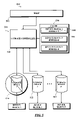
- FIG. 1 is an illustration of an exemplary system of the present invention wherein;
- FIG. 2 is an illustration of an embodiment of the present invention wherein a cache block descriptor is shown
- FIG. 3A is an illustration of an embodiment of the present invention wherein a cache block descriptor including a “present” field is shown;
- FIG. 3B is an illustration of an embodiment of the present invention wherein a system employing a cache block descriptor including a “present” field is employed;
- FIG. 4A is an illustration of an embodiment of the present invention wherein a cache block descriptor including a “modified” field is shown;
- FIG. 4B is an illustration of an embodiment of the present invention wherein a system employing a cache block descriptor including a “modified” field is employed;
- FIG. 5 is an illustration of an example of the present invention wherein a system employing a cache block descriptor including a “pinned” field is embodied;
- FIG. 6 is an illustration of an embodiment of the present invention wherein a system employing a cache block descriptor including a “write-in-progress” field is implemented;
- FIG. 7 is an illustration of an embodiment of the present invention wherein other cache placement for communicatively coupling a cache with a storage controller are shown.
- Cache have been provided in conjunction with storage controllers to increase the efficiency of the controller when receiving and sending data to a host, as well as obtaining and writing data to a storage device.
- storage controllers to increase the efficiency of the controller when receiving and sending data to a host, as well as obtaining and writing data to a storage device.
- a system 100 having a host coupled to a storage apparatus includes a cache for optimizing operations.
- An electronic data storage apparatus 102 may be communicatively coupled to a host 104 to provide data storage operations for the host, such as reading and writing data to and from storage devices.
- the data storage apparatus 102 may include a storage controller 106 to control data operations of storage devices 108 , 110 & 112 .
- the storage controller 106 may implement a variety of operations, such as to provide redundancy to data by incorporating data storage protocols, such as RAID protocols, persistence of data so that data is accessible even in the event of failure of one of the storage devices 108 , 110 , & 112 , and the like.
- a cache 114 may be provided.
- the cache 114 stages data, obtained from either the host or storage devices, for desired operations.
- a storage controller 106 may stage data 116 , 118 & 120 obtained from storage devices 108 , 110 & 112 as cache blocks 122 , 124 & 126 to anticipate data that may be needed by a host 104 .
- Storage controllers previously utilized small cache blocks to optimize cache usage and minimize inadvertent staging of data not needed by a host, or utilized large cache blocks to adequately anticipate host requests.
- the present invention provides a method to achieve a balance between the size of storage controller cache blocks and the amount of data transferred into a cache in anticipation of host requests by providing a cache descriptor data structure that defines data contained in each cache block 122 , 124 & 126 , and further defines for device blocks within the cache blocks the presence or absence of a condition.
- a cache descriptor of the present invention may include variety of fields to describe device blocks included within a cache block as contemplated by a person of ordinary skill in the art. Operations may then by performed by a storage controller based on a field indicating a presence or absence of a condition of a corresponding device block as indicated by the field.
- a cache block descriptor 202 may include device block fields 204 , 206 & 208 for defining corresponding device blocks. By utilizing fields of the present invention, granularity may be achieved down to an individual device block without affecting the size of a cache block. Fields for defining device blocks may describe a variety of conditions, such as “present,” “modified,” “pinned,” and “write-in-progress” which will be described in further detail later in the description. The field may be implemented through one or more binary flags to denote, for each device block within a cache block, the presence or absence of a condition.
- a cache block descriptor 302 includes device block fields 304 , 306 & 308 having a “present” field 310 , 312 & 314 .
- the device block fields 304 , 306 & 308 correspond to device blocks of a cache block.
- the “present” field indicates whether a corresponding device block is present within a cache.
- the present fields allow a cache block to be sparse, i.e. not completely filled.
- a storage controller may stage data specifically requested by a host, with a minimal waste of caching storage. This also allows individual device blocks to be flushed from memory without flushing an entire cache block.
- the system 350 may include a data storage apparatus 352 communicatively coupled to a host.
- a host 354 may request data from the data storage apparatus 352 . Therefore, a storage controller 356 may obtain the desired data from storage devices 358 , 360 & 362 communicatively coupled to the storage controller 356 .
- the host may have specified specific data.
- the storage controller 356 may locate the specific data requested, even if that data is less than a cache block amount. For instance, the storage controller may obtain a cache block including a first device block 364 , a second device block 366 and an “nth” device block 368 . However, the second device block 366 of the cache block may not have been specifically requested by the host. Therefore, the storage controller 356 may read and store the first device block 364 through the “nth” device block 368 , but not the second device block 366 .
- the “present ” field of the first device block through the “nth” device block may be denoted as present 370 & 374 , but the “present” field of the second block is marked as not present 372 .
- the storage controller may obtain the requested data without unnecessarily filling a cache, thereby conserving resources in both reading and transferring the data, as well cache resources by only storing desired data.
- an intervening block may be written to improve the overall efficiency of an operation.
- blocks that are already staged may be re-staged, and blocks not modified may be destaged if doing so would shorten input/output (I/O) time.
- I/O input/output
- a single staged or unmodified block exists between two ranges that need to be read or written, one must start two I/O operations, one for the first range, and one for the second.
- Certain physical storage devices may have long I/O startup times, and thus it may be faster to merge the operations into a single I/O, even if it results in an unnecessary data transfer of the intervening block.
- a cache block descriptor includes “modified” fields to describe whether device blocks within a cache have been modified.
- a cache descriptor 402 may include device block fields 404 , 406 & 408 which correspond to device blocks of a cache block.
- the fields include a “modified” field 410 , 412 & 414 to indicate whether a device block has been modified.
- a device block may have been modified by data transfer from a host, but the data may not yet have been written to a storage device.
- a storage controller may determine what blocks have been modified, and therefore may perform a write including those blocks in an efficient manner by not needing to rewrite unchanged data.
- a system 450 of the present invention employing a cache descriptor including a “modified” field of FIG. 4A .
- the system 450 includes a storage apparatus 452 coupled to a host 454 as before.
- a device block 458 has been modified by a data transfer from a host 454
- other device blocks 456 & 460 of a cache block have not been modified. Therefore, “modified” fields 462 , 464 & 466 of a cache descriptor corresponding to the device blocks may be specified accordingly.
- a storage controller 468 of the data storage apparatus 452 may readily determine which device blocks have been modified, and then write the block 458 a to a storage device without writing blocks 456 & 460 which were not modified.
- system resources may be conserved by writing only that data that has been changed, thereby improving the data storage apparatus performance and efficiency.
- non-modified blocks may be written in some instances to improve efficiency of the operation.
- a storage device may have long I/O startup times, thus, it may be faster to write all of the blocks, whether modified or unmodified, to storage devices in the same operation, even if it means unnecessary data transfer of an intervening block.
- a system 500 of the present invention is shown wherein a “pinned” field corresponding to a device block of a cache block is utilized by a system to denote device unavailability.
- a data storage system may encounter instances in which a storage device within the system may become unavailable, such as due to device failure, communication or device path failure, and the like. However, even in instances of such failure, other storage devices may still be operational. Therefore, the present invention provides a “pinned” field to denote the unavailability to device blocks of a cache block, thereby permitting granularity greater than at a cache block level to enable data to be read and/or written to operational devices.
- the “pinned” field may be utilized to keep data that cannot be written to a storage device because of partial or complete unavailability, such as a device with a defective block or device that has lost power, and the like.
- the “pinned” field informs the caching system that this data cannot be flushed from the cache, and may inform the system that the corresponding data must be backed up to alternate internal and/or external non-volatile storage. In other embodiments, this field may be used to cause subsequent host I/O to be rejected, or subsequent writes to the same block to be rejected.
- a host may be communicatively coupled to a data storage apparatus 504 to obtain data storage functionality.
- a storage controller 506 controls operation of the data storage apparatus 504 , thereby enabling such functionality as data access, striping, parity data and the like.
- a cache 508 may be included to further optimize operations of the data storage apparatus 504 .
- the cache 508 may include cache blocks which include data blocks that were obtained from storage devices 510 , 512 & 514 . For instance, a single cache block may include data obtained from multiple storage devices.
- a “pinned” field for a device block of a cache block is defined to indicate the status of the device. For instance, a “pinned” field 516 corresponding to a first data block 518 was previously stored on a first storage device 510 may indicate unavailability of the storage device. Therefore, by noting the unavailability, the controller may take corrective action, such as to move data to alternate nonvolatile storage devices 512 & 514 .
- the present invention provides the ability to denote device availability for device blocks and enables corrective action to be taken at a sub-cache block level.
- a cache 602 may be utilized to hold data before it is written to storage devices 606 , 608 & 610 for nonvolatile storage by a storage controller 604 , to provide persistent data storage.
- the storage controller may set a “write-in-progress” field to indicate the writing of the block.
- a cache block may include three device blocks 612 , 614 & 616 , the second of which 614 is being written 614 a to a storage device 608 .
- the “write-in-progress” field indicates that the write is being performed.
- the “write-in-progress” field may be set by the storage controller 604 in a variety of ways, such as by changing the indication before the write is transferred, during initiation of a write, and the like as contemplated by a person of ordinary skill in the art. In this way, a storage controller may be prohibited from destaging data more than once, such as if the host writes the same data multiple times.
- an “exclusive lock” field may be used to indicate that a cache block is being modified, such as by host writes, data staged, and the like, to give one process an exclusive lock on the data.
- a “shared lock” field may be used to indicate that a cache block is being read by a host, or that data is being destaged. Any number of concurrent processes may have a shared lock, but a shared lock cannot be held while an exclusive lock is held.
- a “device ID” field may also be used to identify the device whose data is being cached in the cache block.
- a “block number” field may be utilized to indicate the starting block number of the data being cached in the cache block, and a “storage address” field may be utilized to indicate the storage address of cached user data.
- a “hash table queue element” field may be used to indicate each cached block as a member of a linked list of blocks that are found by a hashing mechanism to minimize block search time, when blocks are accessed the hash queue is reordered to minimize subsequent hash table searches. Additionally, a “least recently used” (LRU) field may be utilized to indicate each cached block as a member of a linked list that is reordered when blocks are accessed. When a new cache block needs to be allocated and there is no free storage to do so, blocks are “stolen” from the bottom of the LRU list, thus, the blocks least recently accessed are used.
- LRU least recently used
- the present invention simplifies fault tolerant designs in a number of ways. Storage controller performance is improved because less data is copied among redundant storage controllers. Also, host performance is improved because smaller ranges of data are locked during access, allowing for host I/O operation overlap.
- a cache may be “positioned” in a variety of ways as contemplated by a person of ordinary skill in the art.
- caches are provided in a variety of locations depending on the cache functionality desired.
- a data storage system may include a storage controller 702 communicatively coupled to a host 704 and storage devices 706 .
- a cache 708 may be positioned between the host 704 and the storage controller 702 to provide caching improvement to an existing storage controller.
- a cache 710 may be positioned between the storage controller 702 and storage devices 706 to improve physical device access.
Abstract
Description
Claims (19)
Priority Applications (1)
| Application Number | Priority Date | Filing Date | Title |
|---|---|---|---|
| US10/135,209 US7080207B2 (en) | 2002-04-30 | 2002-04-30 | Data storage apparatus, system and method including a cache descriptor having a field defining data in a cache block |
Applications Claiming Priority (1)
| Application Number | Priority Date | Filing Date | Title |
|---|---|---|---|
| US10/135,209 US7080207B2 (en) | 2002-04-30 | 2002-04-30 | Data storage apparatus, system and method including a cache descriptor having a field defining data in a cache block |
Publications (2)
| Publication Number | Publication Date |
|---|---|
| US20030204677A1 US20030204677A1 (en) | 2003-10-30 |
| US7080207B2 true US7080207B2 (en) | 2006-07-18 |
Family
ID=29249405
Family Applications (1)
| Application Number | Title | Priority Date | Filing Date |
|---|---|---|---|
| US10/135,209 Expired - Fee Related US7080207B2 (en) | 2002-04-30 | 2002-04-30 | Data storage apparatus, system and method including a cache descriptor having a field defining data in a cache block |
Country Status (1)
| Country | Link |
|---|---|
| US (1) | US7080207B2 (en) |
Cited By (14)
| Publication number | Priority date | Publication date | Assignee | Title |
|---|---|---|---|---|
| US20030187960A1 (en) * | 2002-03-26 | 2003-10-02 | Kabushiki Kaisha Toshiba | Data transfer scheme for reducing network load using general purpose browser on client side |
| US20040172319A1 (en) * | 1997-01-06 | 2004-09-02 | Eder Jeff Scott | Value chain system |
| US20040199445A1 (en) * | 2000-10-17 | 2004-10-07 | Eder Jeff Scott | Business activity management system |
| US20050119900A1 (en) * | 2002-06-12 | 2005-06-02 | Eder Jeff S. | Purchasing optimization system |
| US20050228954A1 (en) * | 2003-03-11 | 2005-10-13 | International Business Machines Corporation | Method, system, and program for improved throughput in remote mirroring systems |
| US20050251468A1 (en) * | 2000-10-04 | 2005-11-10 | Eder Jeff S | Process management system |
| US20080004922A1 (en) * | 1997-01-06 | 2008-01-03 | Jeff Scott Eder | Detailed method of and system for modeling and analyzing business improvement programs |
| US20080071588A1 (en) * | 1997-12-10 | 2008-03-20 | Eder Jeff S | Method of and system for analyzing, modeling and valuing elements of a business enterprise |
| US20090018891A1 (en) * | 2003-12-30 | 2009-01-15 | Jeff Scott Eder | Market value matrix |
| US20090043637A1 (en) * | 2004-06-01 | 2009-02-12 | Eder Jeffrey Scott | Extended value and risk management system |
| US20090171740A1 (en) * | 2002-09-09 | 2009-07-02 | Jeffrey Scott Eder | Contextual management system |
| US20130219126A1 (en) * | 2007-04-09 | 2013-08-22 | Ivan Schreter | Wait-Free Parallel Data Cache |
| US8713025B2 (en) | 2005-03-31 | 2014-04-29 | Square Halt Solutions, Limited Liability Company | Complete context search system |
| US8850114B2 (en) | 2010-09-07 | 2014-09-30 | Daniel L Rosenband | Storage array controller for flash-based storage devices |
Families Citing this family (10)
| Publication number | Priority date | Publication date | Assignee | Title |
|---|---|---|---|---|
| US6904501B1 (en) * | 2002-06-17 | 2005-06-07 | Silicon Graphics, Inc. | Cache memory for identifying locked and least recently used storage locations |
| US7853695B2 (en) * | 2003-02-21 | 2010-12-14 | Microsoft Corporation | Using expressive session information to represent communication sessions in a distributed system |
| JP4257785B2 (en) * | 2003-04-22 | 2009-04-22 | 株式会社日立製作所 | Cache storage device |
| US10055360B2 (en) * | 2015-12-19 | 2018-08-21 | Intel Corporation | Apparatus and method for shared least recently used (LRU) policy between multiple cache levels |
| US10719245B1 (en) | 2017-07-13 | 2020-07-21 | EMC IP Holding Company LLC | Transactional IO scheduler for storage systems with multiple storage devices |
| US10509739B1 (en) | 2017-07-13 | 2019-12-17 | EMC IP Holding Company LLC | Optimized read IO for mix read/write scenario by chunking write IOs |
| US10346054B1 (en) * | 2017-07-13 | 2019-07-09 | EMC IP Holding Company LLC | Policy driven IO scheduler resilient to storage subsystem performance |
| US10599340B1 (en) | 2017-07-13 | 2020-03-24 | EMC IP Holding LLC | Policy driven IO scheduler to improve read IO performance in hybrid storage systems |
| US10592123B1 (en) | 2017-07-13 | 2020-03-17 | EMC IP Holding Company LLC | Policy driven IO scheduler to improve write IO performance in hybrid storage systems |
| US10372624B2 (en) | 2017-08-18 | 2019-08-06 | International Business Machines Corporation | Destaging pinned retryable data in cache |
Citations (5)
| Publication number | Priority date | Publication date | Assignee | Title |
|---|---|---|---|---|
| US3840863A (en) * | 1973-10-23 | 1974-10-08 | Ibm | Dynamic storage hierarchy system |
| US5787242A (en) * | 1995-12-29 | 1998-07-28 | Symbios Logic Inc. | Method and apparatus for treatment of deferred write data for a dead raid device |
| US6029229A (en) * | 1997-01-29 | 2000-02-22 | Emc Corporation | Digital data storage subsystem including directory for efficiently providing formatting information for stored records |
| US6073209A (en) * | 1997-03-31 | 2000-06-06 | Ark Research Corporation | Data storage controller providing multiple hosts with access to multiple storage subsystems |
| US6108100A (en) * | 1998-02-20 | 2000-08-22 | Hewlett-Packard Company | Apparatus and method for end-user performance upgrade |
-
2002
- 2002-04-30 US US10/135,209 patent/US7080207B2/en not_active Expired - Fee Related
Patent Citations (5)
| Publication number | Priority date | Publication date | Assignee | Title |
|---|---|---|---|---|
| US3840863A (en) * | 1973-10-23 | 1974-10-08 | Ibm | Dynamic storage hierarchy system |
| US5787242A (en) * | 1995-12-29 | 1998-07-28 | Symbios Logic Inc. | Method and apparatus for treatment of deferred write data for a dead raid device |
| US6029229A (en) * | 1997-01-29 | 2000-02-22 | Emc Corporation | Digital data storage subsystem including directory for efficiently providing formatting information for stored records |
| US6073209A (en) * | 1997-03-31 | 2000-06-06 | Ark Research Corporation | Data storage controller providing multiple hosts with access to multiple storage subsystems |
| US6108100A (en) * | 1998-02-20 | 2000-08-22 | Hewlett-Packard Company | Apparatus and method for end-user performance upgrade |
Cited By (22)
| Publication number | Priority date | Publication date | Assignee | Title |
|---|---|---|---|---|
| US20040172319A1 (en) * | 1997-01-06 | 2004-09-02 | Eder Jeff Scott | Value chain system |
| US20040210509A1 (en) * | 1997-01-06 | 2004-10-21 | Eder Jeff Scott | Automated method of and system for identifying, measuring and enhancing categories of value for a value chain |
| US20080004922A1 (en) * | 1997-01-06 | 2008-01-03 | Jeff Scott Eder | Detailed method of and system for modeling and analyzing business improvement programs |
| US20080313065A1 (en) * | 1997-01-06 | 2008-12-18 | Jeff Scott Eder | Method of and system for analyzing, modeling and valuing elements of a business enterprise |
| US20080071588A1 (en) * | 1997-12-10 | 2008-03-20 | Eder Jeff S | Method of and system for analyzing, modeling and valuing elements of a business enterprise |
| US20050251468A1 (en) * | 2000-10-04 | 2005-11-10 | Eder Jeff S | Process management system |
| US20040199445A1 (en) * | 2000-10-17 | 2004-10-07 | Eder Jeff Scott | Business activity management system |
| US20090132448A1 (en) * | 2000-10-17 | 2009-05-21 | Jeffrey Scott Eder | Segmented predictive model system |
| US20090070182A1 (en) * | 2000-10-17 | 2009-03-12 | Jeffrey Scott Eder | Organization activity management system |
| US20080183845A1 (en) * | 2002-03-26 | 2008-07-31 | Kabushiki Kaisha Toshiba | Data transfer scheme for reducing network load using general purpose browser on client side |
| US20030187960A1 (en) * | 2002-03-26 | 2003-10-02 | Kabushiki Kaisha Toshiba | Data transfer scheme for reducing network load using general purpose browser on client side |
| US7334023B2 (en) * | 2002-03-26 | 2008-02-19 | Kabushiki Kaisha Toshiba | Data transfer scheme for reducing network load using general purpose browser on client side |
| US20050119900A1 (en) * | 2002-06-12 | 2005-06-02 | Eder Jeff S. | Purchasing optimization system |
| US20090171740A1 (en) * | 2002-09-09 | 2009-07-02 | Jeffrey Scott Eder | Contextual management system |
| US20050228954A1 (en) * | 2003-03-11 | 2005-10-13 | International Business Machines Corporation | Method, system, and program for improved throughput in remote mirroring systems |
| US7581063B2 (en) | 2003-03-11 | 2009-08-25 | International Business Machines Corporation | Method, system, and program for improved throughput in remote mirroring systems |
| US20090018891A1 (en) * | 2003-12-30 | 2009-01-15 | Jeff Scott Eder | Market value matrix |
| US20090043637A1 (en) * | 2004-06-01 | 2009-02-12 | Eder Jeffrey Scott | Extended value and risk management system |
| US8713025B2 (en) | 2005-03-31 | 2014-04-29 | Square Halt Solutions, Limited Liability Company | Complete context search system |
| US20130219126A1 (en) * | 2007-04-09 | 2013-08-22 | Ivan Schreter | Wait-Free Parallel Data Cache |
| US9280489B2 (en) * | 2007-04-09 | 2016-03-08 | Sap Se | Wait-free parallel data cache |
| US8850114B2 (en) | 2010-09-07 | 2014-09-30 | Daniel L Rosenband | Storage array controller for flash-based storage devices |
Also Published As
| Publication number | Publication date |
|---|---|
| US20030204677A1 (en) | 2003-10-30 |
Similar Documents
| Publication | Publication Date | Title |
|---|---|---|
| US7080207B2 (en) | Data storage apparatus, system and method including a cache descriptor having a field defining data in a cache block | |
| CN101241457B (en) | Destage management method and system of redundant data copies | |
| US7996609B2 (en) | System and method of dynamic allocation of non-volatile memory | |
| US7213110B2 (en) | Destaging method for storage apparatus system, and disk control apparatus, storage apparatus system and program | |
| US9081691B1 (en) | Techniques for caching data using a volatile memory cache and solid state drive | |
| US5640530A (en) | Use of configuration registers to control access to multiple caches and nonvolatile stores | |
| US7793061B1 (en) | Techniques for using flash-based memory as a write cache and a vault | |
| US7783850B2 (en) | Method and apparatus for master volume access during volume copy | |
| US7111134B2 (en) | Subsystem and subsystem processing method | |
| US20040148360A1 (en) | Communication-link-attached persistent memory device | |
| US20060129763A1 (en) | Virtual cache for disk cache insertion and eviction policies and recovery from device errors | |
| CN1821980A (en) | Apparatus, system, and method for storing modified data | |
| KR20150105323A (en) | Method and system for data storage | |
| JP2005276208A (en) | Communication-link-attached permanent memory system | |
| US8321628B2 (en) | Storage system, storage control device, and method | |
| US6766414B2 (en) | Methods, apparatus and system for caching data | |
| US8762636B2 (en) | Data storage system having a global cache memory distributed among non-volatile memories within system disk drives | |
| US11288197B2 (en) | Method and apparatus for performing pipeline-based accessing management in a storage server | |
| CN110795279A (en) | System and method for facilitating DRAM data cache dump and rack level battery backup | |
| JP2006099802A (en) | Storage controller, and control method for cache memory | |
| Dell | ||
| Dell | ||
| US7089357B1 (en) | Locally buffered cache extensions having associated control parameters to determine use for cache allocation on subsequent requests | |
| JP2023110180A (en) | Storage apparatus and control method |
Legal Events
| Date | Code | Title | Description |
|---|---|---|---|
| AS | Assignment |
Owner name: LSI LOGIC CORPORATION, CALIFORNIA Free format text: ASSIGNMENT OF ASSIGNORS INTEREST;ASSIGNOR:BERGSTEN, JAMES R.;REEL/FRAME:012858/0282 Effective date: 20020430 |
|
| FEPP | Fee payment procedure |
Free format text: PAYOR NUMBER ASSIGNED (ORIGINAL EVENT CODE: ASPN); ENTITY STATUS OF PATENT OWNER: LARGE ENTITY |
|
| FPAY | Fee payment |
Year of fee payment: 4 |
|
| FPAY | Fee payment |
Year of fee payment: 8 |
|
| AS | Assignment |
Owner name: DEUTSCHE BANK AG NEW YORK BRANCH, AS COLLATERAL AG Free format text: PATENT SECURITY AGREEMENT;ASSIGNORS:LSI CORPORATION;AGERE SYSTEMS LLC;REEL/FRAME:032856/0031 Effective date: 20140506 |
|
| AS | Assignment |
Owner name: LSI CORPORATION, CALIFORNIA Free format text: CHANGE OF NAME;ASSIGNOR:LSI LOGIC CORPORATION;REEL/FRAME:033102/0270 Effective date: 20070406 |
|
| AS | Assignment |
Owner name: AVAGO TECHNOLOGIES GENERAL IP (SINGAPORE) PTE. LTD Free format text: ASSIGNMENT OF ASSIGNORS INTEREST;ASSIGNOR:LSI CORPORATION;REEL/FRAME:035390/0388 Effective date: 20140814 |
|
| AS | Assignment |
Owner name: AGERE SYSTEMS LLC, PENNSYLVANIA Free format text: TERMINATION AND RELEASE OF SECURITY INTEREST IN PATENT RIGHTS (RELEASES RF 032856-0031);ASSIGNOR:DEUTSCHE BANK AG NEW YORK BRANCH, AS COLLATERAL AGENT;REEL/FRAME:037684/0039 Effective date: 20160201 Owner name: LSI CORPORATION, CALIFORNIA Free format text: TERMINATION AND RELEASE OF SECURITY INTEREST IN PATENT RIGHTS (RELEASES RF 032856-0031);ASSIGNOR:DEUTSCHE BANK AG NEW YORK BRANCH, AS COLLATERAL AGENT;REEL/FRAME:037684/0039 Effective date: 20160201 |
|
| AS | Assignment |
Owner name: BANK OF AMERICA, N.A., AS COLLATERAL AGENT, NORTH CAROLINA Free format text: PATENT SECURITY AGREEMENT;ASSIGNOR:AVAGO TECHNOLOGIES GENERAL IP (SINGAPORE) PTE. LTD.;REEL/FRAME:037808/0001 Effective date: 20160201 Owner name: BANK OF AMERICA, N.A., AS COLLATERAL AGENT, NORTH Free format text: PATENT SECURITY AGREEMENT;ASSIGNOR:AVAGO TECHNOLOGIES GENERAL IP (SINGAPORE) PTE. LTD.;REEL/FRAME:037808/0001 Effective date: 20160201 |
|
| AS | Assignment |
Owner name: AVAGO TECHNOLOGIES GENERAL IP (SINGAPORE) PTE. LTD., SINGAPORE Free format text: TERMINATION AND RELEASE OF SECURITY INTEREST IN PATENTS;ASSIGNOR:BANK OF AMERICA, N.A., AS COLLATERAL AGENT;REEL/FRAME:041710/0001 Effective date: 20170119 Owner name: AVAGO TECHNOLOGIES GENERAL IP (SINGAPORE) PTE. LTD Free format text: TERMINATION AND RELEASE OF SECURITY INTEREST IN PATENTS;ASSIGNOR:BANK OF AMERICA, N.A., AS COLLATERAL AGENT;REEL/FRAME:041710/0001 Effective date: 20170119 |
|
| FEPP | Fee payment procedure |
Free format text: MAINTENANCE FEE REMINDER MAILED (ORIGINAL EVENT CODE: REM.) |
|
| LAPS | Lapse for failure to pay maintenance fees |
Free format text: PATENT EXPIRED FOR FAILURE TO PAY MAINTENANCE FEES (ORIGINAL EVENT CODE: EXP.) |
|
| STCH | Information on status: patent discontinuation |
Free format text: PATENT EXPIRED DUE TO NONPAYMENT OF MAINTENANCE FEES UNDER 37 CFR 1.362 |
|
| FP | Lapsed due to failure to pay maintenance fee |
Effective date: 20180718 |