US7080274B2 - System architecture and method for synchronization of real-time clocks in a document processing system - Google Patents
System architecture and method for synchronization of real-time clocks in a document processing system Download PDFInfo
- Publication number
- US7080274B2 US7080274B2 US09/938,237 US93823701A US7080274B2 US 7080274 B2 US7080274 B2 US 7080274B2 US 93823701 A US93823701 A US 93823701A US 7080274 B2 US7080274 B2 US 7080274B2
- Authority
- US
- United States
- Prior art keywords
- resource
- clock
- controller
- processing system
- document processing
- Prior art date
- Legal status (The legal status is an assumption and is not a legal conclusion. Google has not performed a legal analysis and makes no representation as to the accuracy of the status listed.)
- Expired - Lifetime, expires
Links
- 238000012545 processing Methods 0.000 title claims abstract description 72
- 238000000034 method Methods 0.000 title claims abstract description 18
- 230000001360 synchronised effect Effects 0.000 claims description 17
- 238000012546 transfer Methods 0.000 claims description 7
- 230000000737 periodic effect Effects 0.000 claims description 6
- GNFTZDOKVXKIBK-UHFFFAOYSA-N 3-(2-methoxyethoxy)benzohydrazide Chemical compound COCCOC1=CC=CC(C(=O)NN)=C1 GNFTZDOKVXKIBK-UHFFFAOYSA-N 0.000 claims 2
- 238000009429 electrical wiring Methods 0.000 claims 1
- 238000004891 communication Methods 0.000 description 11
- 230000008901 benefit Effects 0.000 description 6
- 238000010586 diagram Methods 0.000 description 4
- 238000007639 printing Methods 0.000 description 4
- 230000004075 alteration Effects 0.000 description 2
- 230000000694 effects Effects 0.000 description 2
- 238000012986 modification Methods 0.000 description 2
- 230000004048 modification Effects 0.000 description 2
- 238000012356 Product development Methods 0.000 description 1
- 230000015556 catabolic process Effects 0.000 description 1
- 239000003086 colorant Substances 0.000 description 1
- 230000002860 competitive effect Effects 0.000 description 1
- 238000006731 degradation reaction Methods 0.000 description 1
- 230000001934 delay Effects 0.000 description 1
- 238000013461 design Methods 0.000 description 1
- 238000011161 development Methods 0.000 description 1
- 238000005516 engineering process Methods 0.000 description 1
- 230000010354 integration Effects 0.000 description 1
- 238000002955 isolation Methods 0.000 description 1
- 230000003287 optical effect Effects 0.000 description 1
- 239000013307 optical fiber Substances 0.000 description 1
- 230000008569 process Effects 0.000 description 1
- 230000003134 recirculating effect Effects 0.000 description 1
- 230000003252 repetitive effect Effects 0.000 description 1
- 239000002699 waste material Substances 0.000 description 1
Images


Classifications
-
- G—PHYSICS
- G06—COMPUTING; CALCULATING OR COUNTING
- G06F—ELECTRIC DIGITAL DATA PROCESSING
- G06F1/00—Details not covered by groups G06F3/00 - G06F13/00 and G06F21/00
- G06F1/04—Generating or distributing clock signals or signals derived directly therefrom
- G06F1/14—Time supervision arrangements, e.g. real time clock
Definitions
- the present invention relates to a system architecture for a document processing system. It finds particular application in conjunction with synchronization of a real-time clock in one or more modules of a multiple feeding and finishing architecture with a master real-time clock in a controller of the document processing system and will be described with particular reference thereto. However, it is to be appreciated that the present invention is also amenable to other like applications.
- Platteter '775 permitted the document feeding and/or finishing modules to be interconnected with the print engine in a networked environment and organized in a sequence that meets the customer's needs for a fully automated job. This permitted finishing or feeder devices to be attached in any order that the operator decided was appropriate for the application.
- feeding and finishing modules in the networked MFFA include clocks that must be accurately synchronized with a master clock in the master module, the print engine, in order to correctly perform the printing function. This is because the master module controls all the scheduling between the feeding and finishing modules. As document processing systems became more sophisticated the accuracy and precision of the synchronization have become more and more important.
- Clock synchronization in the networked MFFA was initially implemented to synchronize the clocks within the feeding and finishing modules using only the network. Due to delays in communications over the network, this type of clock synchronization is no longer sufficient. Network delay is particularly a problem when more than several feeding and/or finishing modules are configured in the document processing system. In other words, as more feeding and finishing modules are added to the system, the delay over the network increases, causing the synchronization of the module clocks with the master clock to be unpredictable, thereby unreliable, and often with unacceptable error. Additionally, variability of network delay occurred due to fluctuations in network traffic as the network was used for communications other than clock synchronization.
- the clock synchronization algorithm was typically designed with the feeding and finishing modules requesting the current master clock time and master module responding to the request, both via the network. More specifically, the basic algorithm went as follows: 1) First, a slave module (i.e., feeding or finishing module) read and saved the current value of its clock. 2) The slave module then sent a request, over the network, to the master module requesting a read of the master clock. 3) The master module then read its clock and sent the time value back to the slave module over the network. 4) On receipt of the message from the master module, the slave again read the value of its clock. 5) The slave module then subtracted the two readings it had done of its clock and divided the result by two (2) to get one-half of the delay over the network.
- a slave module i.e., feeding or finishing module
- the slave then added the result (one-half the delay) to the master clock reading sent by the master module. 7) The slave then compared the adjusted master clock time to the last reading it had done of its clock. The comparison determined whether there was error between the two clocks. 8) Finally, the slave module then adjusted its clock appropriately to account for the error.
- the present invention contemplates a new and improved method for clock synchronization in a networked MFFA configuration of a document processing system that overcomes the above-referenced problems and others.
- a document processing system is provided.
- the document processing system is comprised of a controller, including a master clock and logic for generating a discrete clock synchronization interrupt signal; a resource, including a slave clock related to operational timing of the resource and circuitry for receiving and processing the discrete interrupt signal; and a control bus, interconnecting the resource and the controller, for distributing the discrete interrupt signal.
- a method for initially synchronizing the slave clock with the master clock of the document processing system.
- the method comprising the steps of: a) saving a value of the master clock in the controller; b) generating a discrete clock synchronization interrupt signal in the controller and distributing the discrete interrupt signal to the resource via the control bus; c) receiving the discrete interrupt signal at the resource and saving a first value of the slave clock; d) sending a message from the resource to the controller via a network to request the value saved for the master clock; e) sending the value saved for the master clock from the controller to the resource via the network; f) receiving the value saved for the master clock at the resource; g) saving a second value of the slave clock in the resource; h) subtracting the first value from the second value to determine a slave clock difference value; and i) adding the difference value to the value saved for the master clock to determine a synchronized value for the slave clock and setting the slave clock to the synchronized
- a method for synchronizing the slave clock with the master clock during steady state operation of the document processing system.
- the method comprising the steps of: a) saving a value of the master clock in the controller; b) generating a discrete clock synchronization interrupt signal in the controller and distributing the discrete interrupt signal to the resource via the control bus; c) receiving the discrete interrupt signal at the resource and saving a value of the slave clock, d) sending a message from the resource to the controller via a network to request the value saved for the master clock, e) sending the value saved for the master clock from the controller to the resource via the network; f) receiving the value saved for the master clock at the resource; and g) subtracting the value saved for the slave clock from the value saved for the master clock to determine an error value between the slave clock and the master clock and using the error value in an adjustment algorithm to adjust the slave clock to be synchronized with the master clock.
- One advantage of the present invention is that it allows the clocks in resources or slave modules (i.e., feeding or finishing modules) of a document processing system configured in a networked MFFA to be more accurately and precisely synchronized with a master clock within the master module (i.e. print engine or controller) of the system.
- Another advantage of the present invention is that the accuracy and precision of clock synchronization in a document processing system configured in a networked environment is independent of the quantity of feeding and finishing modules attached to the network nor is it affected by changes in the level of network traffic.
- Another advantage of the present invention is that it supports hard real-time service in a document processing system configured in a networked MFFA.
- Another advantage of the present invention is that it can synchronize the slave clock of a module or resource to within one (1) clock cycle of the master clock of the controller in the document processing system.
- the invention may take form in various components and arrangements of components, and in various steps and arrangements of steps.
- the drawings are only for purposes of illustrating preferred embodiments and are not to be construed as limiting the invention.
- FIG. 1 is a block diagram of a document processing system incorporating the present invention
- FIG. 2 is an electrical interconnection diagram of the document processing system of FIG. 1 ;
- FIG. 3 is a more detailed electrical interconnection diagram of the document processing system of FIG. 1 ;
- FIG. 4 is an electrical interconnection diagram showing the clock synchronization interrupt signal in accordance with the present invention.
- FIG. 5 is a flow chart of a first algorithm for synchronization of real-time clocks in a document processing system in accordance with the present invention.
- FIG. 6 is a flow chart of a second algorithm for synchronization of real-time clocks in a document processing system in accordance with the present invention.
- Real-time refers to a type of system where system correctness depends not only on outputs, but the timeliness of those outputs. Failure to meet one or more deadlines can result in system failure.
- Hard real-time service refers to performance guarantees in a real-time system in which missing even one deadline results in system failure.
- Soft real-time service refers to performance guarantees in a real-time system in which failure to meet deadlines results in performance degradation but not necessarily system failure.
- LAN Local area network
- nodes computers or computer-controlled devices
- connection devices e.g., switches and routers
- Each node has its own CPU which controls local operations and communications with other nodes on the LAN.
- LAN connections are through direct cables (e.g., unshielded twisted pair, coaxial cable, or optical fiber).
- Ethernet One of the most common LAN standards is referred to as Ethernet.
- Ethernet refers to a LAN protocol developed by Xerox in cooperation with Digital Equipment Corporation (DEC) and Intel in 1976. Ethernet uses a bus or star topology and supports data transfer rates of 10 megabits per second (Mbps). The Ethernet specification served as the basis for the IEEE 802.3 standard, which specifies the physical and lower software layers.
- 10 Base T refers to a type of cable used to connect nodes on an Ethernet network. 10 refers to the transfer rate used on standard Ethernet, 10 Mbps. Base means that the network uses baseband communication rather than broadband communications; T stands for twisted pair. The 10 Base T standard uses a twisted-pair cable with maximum lengths of 100 meters.
- a document processing system can be comprised of multiple modules or resources (i.e., feeding and finishing devices) attached to a print engine.
- the modules can be added or removed by the user to provide the feeding and/or finishing capabilities they require.
- the modules must be accurately and precisely synchronized with a master module (i.e., print engine) in order to correctly perform the printing function.
- the present invention describes a method that allows the control systems within multiple slave modules or resources of a document processing system to be accurately and precisely synchronized with a master clock contained in the master module in order to provide certain performance guarantees.
- the nature of the performance guarantees that the document processing system must provide can be classified into two broad categories: (1) hard real-time guarantees, when the performance requirements of the system will never be violated and (2) soft real-time guarantees, when the requirements will occasionally, but infrequently, violate the performance requirements.
- the document processing system guarantees apply irrespective of the system functions required to operate simultaneously in order to perform an operation. Consequently, when hard real-time guarantees are required, clock synchronization must be based on the worst-case performance conditions that could be encountered. With soft-real time service, the document processing system cannot guarantee that the performance requirements will be continuously satisfied. Nevertheless, since soft real-time services avoid the worst-case design necessary for hard real-time services, soft real-time services result in a much higher utilization of system resources than hard real-time services.
- the present invention can be implemented for hard real-time service or soft real-time service.
- document processing systems are presumed to require hard real-time service.
- the present invention has been demonstrated to synchronize real-time clocks in slave modules or resources to within one (1) clock cycle of the master clock in the print engine of the document processing system.
- a document processing system in accordance with the present invention comprises a marking engine or printer with multiple attached feeding and/or finishing devices.
- a marking engine or printer 10 including a user interface with screen 11 is interconnected to multiple document feeding devices 12 and 14 and multiple document finishing devices 16 , 18 , and 20 .
- the feeding devices are sources of printable media like paper for providing the printer 10 with stock for completion of the printing process.
- Feeding devices are paper trays, and the need for feeding devices is to supply an increased level of printable stock selection to the printer. This could be for the purpose of having multiple colors of tabs or separating stock or front and rear cover stock with a clear coversheet.
- FIG. 1 is only one embodiment and meant to illustrate a functional view of the devices rather than actual physical placement.
- the feeding and finishing devices ( 12 , 14 , 16 , 18 , 20 ) may be referred to collectively as resources with respect to the marking engine or printer 10 (i.e., print engine) of the document processing system.
- the resources are physically attached to the print engine 10 such that sheets can be fed into the print engine 10 from the feeding devices ( 12 , 14 ) and sheets or sets of sheets can be transferred from the print engine 10 to the finishing devices ( 16 , 18 , 20 ).
- the resources are attached to each other such that sheets or sets of sheets can be transferred from one device to another. It should be understood that the mechanical specifications of how these resources are connected to the print engine 10 or to one another are not part of the present invention.
- FIG. 2 the basic electrical interconnections of the document processing system of FIG. 1 are shown.
- the electrical interconnections depicted in FIG. 2 include a system network 34 (e.g., LAN) and a control bus 36 .
- system network 34 e.g., LAN
- control bus 36 e.g., a system network 34
- FIG. 2 the architecture of FIG. 2 is modular and can include any combination of resources. The architecture allows expansion to include additional resources, while less resources than the configuration of five (5) shown in FIG. 2 are also permitted under the present invention.
- the preferred embodiment of the present invention uses a 10 Base T Ethernet network with nodes connected in a star topology. However, alternate topologies, alternate cabling standards, and alternate network protocol standards that are able to implement synchronization of real-time clocks as described below are also contemplated.
- printed wiring board assembly (PWBA) 26 of feeding device 12 is connected to the system network 34 and the control bus 36 .
- PWBA 24 of feeding device 14 controller PWBA 22 of the print engine 10
- PWBA 28 of finisher device 16 PWBA 30 of finisher device 18
- PWBA 32 of finisher device 20 are also connected to the system network 34 and the control bus 36 .
- Controller PWBA 22 is also commonly referred to as a controller.
- Each resource PWBA ( 24 , 26 , 28 , 30 , 32 ) provides several functions. One is to provide an interface to the system network 34 ; another function is local control of the resource ( 12 , 14 , 16 , 18 , 20 ).
- the resource PWBA ( 24 , 26 , 28 , 30 , 32 ) contains all the software needed to integrate the resource ( 12 , 14 , 16 , 18 , 20 ) into the chain of resources controlled by the print engine and forming the document processing system 10 .
- the communications portion of the software on the resource PWBA ( 24 , 26 , 28 , 30 , 32 ) is common on every PWBA in each of the devices.
- the electrical interconnections include the system network 34 and the control bus 36 .
- the preferred embodiment of the system network 34 is a star topology with the controller 22 and each resource PWBA ( 24 , 26 , 28 , 30 , 32 ) connected through a hub 38 (e.g., router).
- the system network 34 and the hub 38 are responsible for communications between the controller PWBA 22 , located in the print engine 10 , and the resource PWBAs ( 24 , 26 , 28 , 30 , 32 ).
- the system network is a high speed communications network operating at 10 Mbps (e.g., 10 Base T Ethernet) and in one embodiment provides the capability to address from 1 to 32 independent resources.
- the control bus 36 distributes discrete control signals between the controller PWBA 22 and the resource PWBAs ( 24 , 26 , 28 , 30 , 32 ) independent of network communications.
- a discrete clock synchronization interrupt signal is distributed from the controller PWBA 22 to each resource PWBA ( 24 , 26 , 28 , 30 , 32 ) via the control bus 36 .
- Each resource PWBA ( 24 , 26 , 28 , 30 , 32 ) provides isolation of the control bus 36 .
- Each resource PWBA ( 24 , 26 , 28 , 30 , 32 ) also contains intelligence to control its own operation, including timing and functionality specifications that are specific to the particular device. The removal of a device control from the print engine control enables the integration of most any device to the print engine without having to rewrite the print engine control software.
- the controller PWBA 22 includes a master clock 48 related to the operation and timing of the document processing system 10 and a CPU 50 or other circuitry for generating a discrete clock synchronization interrupt signal 40 .
- the CPU 50 in the controller PWBA 22 responds to the operational and timing data of the master clock 48 to operate in accordance with the operation and timing requirements of the document processing system.
- Each resource PWBA ( 24 , 26 , 28 , 30 ) includes a slave clock 42 related to the operation and timing of the related resource ( 12 , 14 , 16 , 18 ) and a CPU 44 or other circuitry for responding to the discrete clock synchronization interrupt signal 40 from the controller PWBA 22 .
- an object of the present invention is to synchronize the slave clocks 42 of the resources ( 12 , 14 , 16 , 18 ) with the master clock 48 of the controller PWBA 22 . More generally, the clock synchronization interrupt signal 40 is used to synchronize operations of all the resources ( 12 , 14 , 16 , 18 ) with the controller 22 , thereby guaranteeing proper real-time operation of the document processing system.
- the clock synchronization interrupt signal 40 is one of the discrete control signals distributed via the control bus 36 . More particularly, the discrete clock synchronization interrupt signal 40 is distributed from the controller PWBA 22 to the resource PWBAs ( 24 , 26 , 28 , 30 ). Each resource must provide a one to one interconnect for the discrete control bus signals from where the signals enter the device and where they exit the device. With reference to FIG. 4 , for a typical resource PWBA, the discrete clock synchronization interrupt signal 40 is optically isolated between the PWBA ( 24 , 26 , 28 , 30 ) and the controller PWBA 22 by an optical buffer 46 .
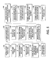
- the present invention provides a first algorithm for synchronization of the slave clock 42 within the resources ( 12 , 14 , 16 , 18 ) with the master clock 48 in the controller 22 of the document processing system.
- This first algorithm is performed one time during initialization of the document processing system.
- the controller starts a periodic timer 505 .
- the periodic timer establishes a repetitive interval for a clock synchronization cycle (e.g., two (2) minutes) within the document processing system during steady state operations.
- the periodic timer expires 510
- the controller reads the current time of its master clock 515 and saves the snapshot time 520 .
- the saved value for the master clock is referred to as Master_Clock_Snapshot_Time.
- the controller sends a clock synchronization interrupt signal to the feeding/finishing resources 525 .
- each resource 12 , 14 , 16 , 18 configured in the document processing system upon receipt of the first clock synchronization interrupt signal 530 after startup.
- the resource After receiving the discrete interrupt, the resource immediately reads the current time of its slave clock 535 and saves the snapshot time 540 .
- the saved value is referred to as Slave_Clock_Snapshot_Time_ 1 .
- the resource sends a message, using the network, to the controller requesting the Master_Clock_Snapshot_Time 545 to be transmitted to it via the network.
- the following steps are performed by the controller 22 each time it receives a request for the last saved Master_Clock_Snapshot_Time 550 .
- the controller retrieves the last saved Master_Clock_Snapshot_Time 555 .
- the controller sends the Master_Clock_Snapshot_Time to the requesting resource over the network 560 .
- each resource 12 , 14 , 16 , 18 ) the first time the resource receives the Master_Clock Snapshot_Time from the controller 565 after startup.
- the resource reads the current time on its slave clock 570 and saves the snapshot time. The saved value is referred to as Slave_Clock_Snapshot_Time_ 2 .
- the resource determines the difference between Slave_Clock_Snapshot_Time_ 1 and Slave_Clock_Snapshot_Time_ 2 575 by subtracting the first snapshot time from the second. The result is the time elapsed since the discrete clock synchronization interrupt was received.
- the resource then adds the difference to the Master_Clock_Snapshot_Time 580 to determine a synchronized value. Finally, the resource transfer this result (i.e., the Master_Clock_Snapshot_Time adjusted for elapsed time) to the slave clock 585 and the slave clock is set to the synchronized value. At this point the slave clock 42 is initially synchronized with the master clock 48 .
- the present invention provides a second algorithm for synchronization of the slave clock 42 within the resources ( 12 , 14 , 16 , 18 ) with the master clock 48 in the controller 22 of the document processing system.
- the second algorithm is performed after the initialization algorithm of FIG. 5 and periodically during steady state operations according to the clock synchronization cycle (e.g., two (2) minutes) established by the controller's periodic timer. Each time the periodic timer expires 610 , the controller reads the current time of its master clock 615 and saves the snapshot time 620 .
- the saved value for the master clock is referred to as Master_Clock_Snapshot_Time.
- the controller sends a clock synchronization interrupt signal to the feeding/finishing resources 625 .
- each resource 12 , 14 , 16 , 18 configured in the document processing system upon receipt of the clock synchronization interrupt signal 630 .
- the resource After receiving the discrete interrupt, the resource immediately reads the current time of its slave clock 635 and saves the snapshot time 640 .
- the saved value is referred to as Slave_Clock_Snapshot_Time.
- the resource sends a message, using the network, to the controller requesting the Master_Clock_Snapshot_Time 645 to be transmitted to it via the network.
- the following steps are performed by the controller 22 each time it receives a request for the last saved Master_Clock_Snapshot_Time 650 .
- the controller retrieves the last saved Master_Clock_Snapshot_Time 655 .
- the controller sends the Master_Clock_Snapshot_Time to the requesting resource over the network 660 .
- each resource determines the difference between Master_Clock_Snapshot_Time and the Slave_Clock_Snapshot_Time 690 by subtracting the slave clock time from the master clock time. The result is the error between the slave clock and the master clock when the clock synchronization interrupt was received.
- the resource then applies an algorithm to gradually adjust the slave clock for the error 695 . Once the adjustment algorithm has eliminated the error or reduced it to acceptable limits, the slave clock 42 is synchronized with the master clock 48 .
- the present invention enables the networked architecture of Platteter '775 to be implemented in document processing systems that provide real-time service, including hard real-time service, independent of the various configurations of feeding and finishing devices available for attachment to the print engine.
- real-time service has been demonstrated by the present invention when the real-time clocks in slave modules or resources are synchronized with the master clock in the print engine.
- the present invention has also demonstrated the ability to synchronize the resource clocks to within one (1) clock cycle of the master clock.
- the present invention also continues to permit development of feeding and finishing devices by third party vendors.
Abstract
Description
Claims (21)
Priority Applications (5)
| Application Number | Priority Date | Filing Date | Title |
|---|---|---|---|
| US09/938,237 US7080274B2 (en) | 2001-08-23 | 2001-08-23 | System architecture and method for synchronization of real-time clocks in a document processing system |
| JP2002240099A JP2003150272A (en) | 2001-08-23 | 2002-08-21 | System architecture and method for synchronization of real-time clock in document processing system |
| BR0203380-1A BR0203380A (en) | 2001-08-23 | 2002-08-21 | System architecture and method for synchronizing real time clocks in a document processing system |
| EP02018928A EP1310857B1 (en) | 2001-08-23 | 2002-08-23 | System and method for synchronisation of real-time clocks in a document processing system |
| DE60221481T DE60221481T2 (en) | 2001-08-23 | 2002-08-23 | System and method for synchronizing real-time clocks in a document processing system |
Applications Claiming Priority (1)
| Application Number | Priority Date | Filing Date | Title |
|---|---|---|---|
| US09/938,237 US7080274B2 (en) | 2001-08-23 | 2001-08-23 | System architecture and method for synchronization of real-time clocks in a document processing system |
Publications (2)
| Publication Number | Publication Date |
|---|---|
| US20030041274A1 US20030041274A1 (en) | 2003-02-27 |
| US7080274B2 true US7080274B2 (en) | 2006-07-18 |
Family
ID=25471152
Family Applications (1)
| Application Number | Title | Priority Date | Filing Date |
|---|---|---|---|
| US09/938,237 Expired - Lifetime US7080274B2 (en) | 2001-08-23 | 2001-08-23 | System architecture and method for synchronization of real-time clocks in a document processing system |
Country Status (5)
| Country | Link |
|---|---|
| US (1) | US7080274B2 (en) |
| EP (1) | EP1310857B1 (en) |
| JP (1) | JP2003150272A (en) |
| BR (1) | BR0203380A (en) |
| DE (1) | DE60221481T2 (en) |
Cited By (2)
| Publication number | Priority date | Publication date | Assignee | Title |
|---|---|---|---|---|
| US20120170597A1 (en) * | 2007-12-31 | 2012-07-05 | Kevin Stanton | Synchronizing multiple system clocks |
| US20130016739A1 (en) * | 2010-04-08 | 2013-01-17 | Nicusor Penisoara | Multi-channel sniffer system and method for multi-channel sniffer synchronization |
Families Citing this family (16)
| Publication number | Priority date | Publication date | Assignee | Title |
|---|---|---|---|---|
| EP1959349B1 (en) * | 2002-07-17 | 2010-12-22 | Chronologic Pty Ltd | Synchronized multichannel universal serial bus |
| KR100597588B1 (en) * | 2003-10-02 | 2006-07-06 | 한국전자통신연구원 | Method for Measurement of Path characteristic between nodes using Active Testing Packet based Priority |
| CN100334521C (en) * | 2004-02-28 | 2007-08-29 | 鸿富锦精密工业(深圳)有限公司 | Clock management system and method |
| US8237949B2 (en) * | 2004-05-18 | 2012-08-07 | Sharp Laboratories Of America, Inc. | System and method for combining at a single location selection of image finishing operations of multiple devices |
| US7440127B2 (en) * | 2004-06-30 | 2008-10-21 | Xerox Corporation | Interface converter for image processing systems |
| JP4298736B2 (en) * | 2005-11-09 | 2009-07-22 | キヤノン株式会社 | Information processing apparatus, electronic document processing method, and program |
| CN103631745A (en) | 2007-05-15 | 2014-03-12 | 克罗诺洛吉克有限公司 | USB based synchronization and timing system |
| US8255708B1 (en) * | 2007-08-10 | 2012-08-28 | Marvell International Ltd. | Apparatuses and methods for power saving in USB devices |
| DE102008049161A1 (en) * | 2008-09-24 | 2010-04-01 | Siemens Aktiengesellschaft | Microprocessor system with several interconnected microprocessors |
| WO2010132947A1 (en) * | 2009-05-20 | 2010-11-25 | Chronologic Pty. Ltd. | Synchronisation and trigger distribution across instrumentation networks |
| JP5509055B2 (en) * | 2009-12-24 | 2014-06-04 | キヤノンファインテック株式会社 | Image forming apparatus |
| US8949648B2 (en) * | 2011-04-13 | 2015-02-03 | Semtech Corp. | System and method to overcome wander accumulation to achieve precision clock distribution over large networks |
| US9335785B2 (en) * | 2011-07-20 | 2016-05-10 | Aviat U.S., Inc. | Systems and methods of clock synchronization between devices on a network |
| EP3045987B1 (en) * | 2013-10-15 | 2020-12-16 | Omron Corporation | Control device and control method |
| CN108134644B (en) * | 2016-12-01 | 2019-10-22 | 中国移动通信有限公司研究院 | Synchronous method, device, synchronizer and system |
| CN113411157B (en) * | 2021-08-20 | 2021-11-09 | 浙江国利信安科技有限公司 | Method, slave clock device, master clock device and system for clock synchronization |
Citations (16)
| Publication number | Priority date | Publication date | Assignee | Title |
|---|---|---|---|---|
| US4190350A (en) * | 1977-08-30 | 1980-02-26 | Donohue James J | Distributed microprocessor control system for a copier/duplicator |
| US4644498A (en) * | 1983-04-04 | 1987-02-17 | General Electric Company | Fault-tolerant real time clock |
| US4807259A (en) * | 1986-05-20 | 1989-02-21 | Mitsubishi Denki Kabushiki Kaisha | Time synchronization method in data transmission system |
| US5327468A (en) | 1992-06-19 | 1994-07-05 | Westinghouse Electric Corp. | Synchronization of time-of-day clocks in a distributed processing network system |
| US5535217A (en) * | 1994-12-20 | 1996-07-09 | International Business Machines Corporation | Method and apparatus for probabilistic clock synchronization with interval arithmetic |
| US5629775A (en) | 1994-07-27 | 1997-05-13 | Xerox Corporation | System architecture for attaching and controlling multiple feeding and finishing devices to a reproduction machine |
| GB2337347A (en) | 1998-02-27 | 1999-11-17 | Lucas Ind Plc | Distributed data processing system |
| US5995771A (en) * | 1997-03-07 | 1999-11-30 | Ricoh Company, Ltd. | Image forming apparatus administration system |
| WO2001022202A1 (en) | 1999-09-17 | 2001-03-29 | Comuniq Asa | Method for synchronizing clocks in electronic units connected to a multi processor data bus |
| US6236277B1 (en) | 1999-09-30 | 2001-05-22 | Rockwell Technologies, Llc | Low deviation synchronization clock |
| US6320424B1 (en) * | 2000-06-30 | 2001-11-20 | Intel Corporation | Method of providing and circuit for providing phase lock loop frequency overshoot control |
| US6343351B1 (en) * | 1998-09-03 | 2002-01-29 | International Business Machines Corporation | Method and system for the dynamic scheduling of requests to access a storage system |
| US6411795B2 (en) * | 2000-02-25 | 2002-06-25 | Ricoh Company, Ltd. | Image forming apparatus with a two-sides image forming operation |
| US6608990B1 (en) * | 2000-10-19 | 2003-08-19 | Heidelberger Druckmaschinen Ag | Job ordering system for an image-forming machine |
| US6675249B2 (en) * | 1999-12-27 | 2004-01-06 | Hitachi, Ltd. | Information processing equipment and information processing system |
| US6704302B2 (en) * | 1999-02-04 | 2004-03-09 | Avaya Technology Corp. | Port prioritizing device |
-
2001
- 2001-08-23 US US09/938,237 patent/US7080274B2/en not_active Expired - Lifetime
-
2002
- 2002-08-21 JP JP2002240099A patent/JP2003150272A/en active Pending
- 2002-08-21 BR BR0203380-1A patent/BR0203380A/en not_active Application Discontinuation
- 2002-08-23 DE DE60221481T patent/DE60221481T2/en not_active Expired - Lifetime
- 2002-08-23 EP EP02018928A patent/EP1310857B1/en not_active Expired - Fee Related
Patent Citations (16)
| Publication number | Priority date | Publication date | Assignee | Title |
|---|---|---|---|---|
| US4190350A (en) * | 1977-08-30 | 1980-02-26 | Donohue James J | Distributed microprocessor control system for a copier/duplicator |
| US4644498A (en) * | 1983-04-04 | 1987-02-17 | General Electric Company | Fault-tolerant real time clock |
| US4807259A (en) * | 1986-05-20 | 1989-02-21 | Mitsubishi Denki Kabushiki Kaisha | Time synchronization method in data transmission system |
| US5327468A (en) | 1992-06-19 | 1994-07-05 | Westinghouse Electric Corp. | Synchronization of time-of-day clocks in a distributed processing network system |
| US5629775A (en) | 1994-07-27 | 1997-05-13 | Xerox Corporation | System architecture for attaching and controlling multiple feeding and finishing devices to a reproduction machine |
| US5535217A (en) * | 1994-12-20 | 1996-07-09 | International Business Machines Corporation | Method and apparatus for probabilistic clock synchronization with interval arithmetic |
| US5995771A (en) * | 1997-03-07 | 1999-11-30 | Ricoh Company, Ltd. | Image forming apparatus administration system |
| GB2337347A (en) | 1998-02-27 | 1999-11-17 | Lucas Ind Plc | Distributed data processing system |
| US6343351B1 (en) * | 1998-09-03 | 2002-01-29 | International Business Machines Corporation | Method and system for the dynamic scheduling of requests to access a storage system |
| US6704302B2 (en) * | 1999-02-04 | 2004-03-09 | Avaya Technology Corp. | Port prioritizing device |
| WO2001022202A1 (en) | 1999-09-17 | 2001-03-29 | Comuniq Asa | Method for synchronizing clocks in electronic units connected to a multi processor data bus |
| US6236277B1 (en) | 1999-09-30 | 2001-05-22 | Rockwell Technologies, Llc | Low deviation synchronization clock |
| US6675249B2 (en) * | 1999-12-27 | 2004-01-06 | Hitachi, Ltd. | Information processing equipment and information processing system |
| US6411795B2 (en) * | 2000-02-25 | 2002-06-25 | Ricoh Company, Ltd. | Image forming apparatus with a two-sides image forming operation |
| US6320424B1 (en) * | 2000-06-30 | 2001-11-20 | Intel Corporation | Method of providing and circuit for providing phase lock loop frequency overshoot control |
| US6608990B1 (en) * | 2000-10-19 | 2003-08-19 | Heidelberger Druckmaschinen Ag | Job ordering system for an image-forming machine |
Cited By (3)
| Publication number | Priority date | Publication date | Assignee | Title |
|---|---|---|---|---|
| US20120170597A1 (en) * | 2007-12-31 | 2012-07-05 | Kevin Stanton | Synchronizing multiple system clocks |
| US8934505B2 (en) * | 2007-12-31 | 2015-01-13 | Intel Corporation | Synchronizing multiple system clocks |
| US20130016739A1 (en) * | 2010-04-08 | 2013-01-17 | Nicusor Penisoara | Multi-channel sniffer system and method for multi-channel sniffer synchronization |
Also Published As
| Publication number | Publication date |
|---|---|
| EP1310857B1 (en) | 2007-08-01 |
| BR0203380A (en) | 2003-05-20 |
| EP1310857A3 (en) | 2006-01-25 |
| EP1310857A2 (en) | 2003-05-14 |
| JP2003150272A (en) | 2003-05-23 |
| DE60221481D1 (en) | 2007-09-13 |
| DE60221481T2 (en) | 2007-11-29 |
| US20030041274A1 (en) | 2003-02-27 |
Similar Documents
| Publication | Publication Date | Title |
|---|---|---|
| US7080274B2 (en) | System architecture and method for synchronization of real-time clocks in a document processing system | |
| US5005122A (en) | Arrangement with cooperating management server node and network service node | |
| TW411424B (en) | Methods and apparatus for isochronous printing with minimal buffering | |
| US5960167A (en) | Printer configuration system | |
| EP0694832B1 (en) | Apparatus and method for attaching and controlling one or more accessory devices to a reproduction machine | |
| CN101164264B (en) | Method and device for synchronising two bus systems, and arrangement consisting of two bus systems | |
| US20160110141A1 (en) | Ethernet and usb powered printers and methods for supplying ethernet and usb power to a printer | |
| JP2008217827A (en) | Method for defining document by assembly tree format | |
| CS520190A3 (en) | Distributed synchronization process for wireless fast packet communication system | |
| EP0830006B1 (en) | Scheduling mode variations for discrete job elements | |
| US20060253824A1 (en) | Software evaluation method and software evaluation system | |
| US20020015177A1 (en) | Print control method and tandem printing system | |
| JP2006059357A (en) | Print sequence scheduling for reliability | |
| CA2247908A1 (en) | Open systems printing | |
| JPH096564A (en) | Apparatus for automatic transmission of event-related information | |
| JP2000158774A (en) | Network print system and waiting work processing method during its print error | |
| JP3640975B2 (en) | Image set provision method | |
| CN1973278A (en) | Method and device for controlling a bus system, and corresponding bus system | |
| US5617214A (en) | Commitment groups to generalize the scheduling of interdependent document output terminal capabilities | |
| US20030237083A1 (en) | Remote installation system and computer apparatus applied to the system | |
| US6760849B1 (en) | Event initiation bus and associated fault protection for a telecommunications device | |
| US20060285547A1 (en) | Loop communication system and communication device | |
| US7440127B2 (en) | Interface converter for image processing systems | |
| US8176156B1 (en) | Server identification assignment in a distributed switched storage environment | |
| US6717692B1 (en) | Image processing system and control method therefor, image processing apparatus, and recording medium |
Legal Events
| Date | Code | Title | Description |
|---|---|---|---|
| AS | Assignment |
Owner name: XEROX CORPORATION, CONNECTICUT Free format text: ASSIGNMENT OF ASSIGNORS INTEREST;ASSIGNORS:PLATTETER, DALE T.;BOSSO, JUDY C.;WESTFALL, ROBERT S.;REEL/FRAME:012130/0717 Effective date: 20010820 |
|
| AS | Assignment |
Owner name: BANK ONE, NA, AS ADMINISTRATIVE AGENT, ILLINOIS Free format text: SECURITY AGREEMENT;ASSIGNOR:XEROX CORPORATION;REEL/FRAME:013111/0001 Effective date: 20020621 Owner name: BANK ONE, NA, AS ADMINISTRATIVE AGENT,ILLINOIS Free format text: SECURITY AGREEMENT;ASSIGNOR:XEROX CORPORATION;REEL/FRAME:013111/0001 Effective date: 20020621 |
|
| AS | Assignment |
Owner name: JPMORGAN CHASE BANK, AS COLLATERAL AGENT, TEXAS Free format text: SECURITY AGREEMENT;ASSIGNOR:XEROX CORPORATION;REEL/FRAME:015134/0476 Effective date: 20030625 Owner name: JPMORGAN CHASE BANK, AS COLLATERAL AGENT,TEXAS Free format text: SECURITY AGREEMENT;ASSIGNOR:XEROX CORPORATION;REEL/FRAME:015134/0476 Effective date: 20030625 |
|
| FEPP | Fee payment procedure |
Free format text: PAYOR NUMBER ASSIGNED (ORIGINAL EVENT CODE: ASPN); ENTITY STATUS OF PATENT OWNER: LARGE ENTITY |
|
| STCF | Information on status: patent grant |
Free format text: PATENTED CASE |
|
| FPAY | Fee payment |
Year of fee payment: 4 |
|
| FPAY | Fee payment |
Year of fee payment: 8 |
|
| MAFP | Maintenance fee payment |
Free format text: PAYMENT OF MAINTENANCE FEE, 12TH YEAR, LARGE ENTITY (ORIGINAL EVENT CODE: M1553) Year of fee payment: 12 |
|
| AS | Assignment |
Owner name: XEROX CORPORATION, CONNECTICUT Free format text: RELEASE BY SECURED PARTY;ASSIGNOR:JPMORGAN CHASE BANK, N.A. AS SUCCESSOR-IN-INTEREST ADMINISTRATIVE AGENT AND COLLATERAL AGENT TO BANK ONE, N.A.;REEL/FRAME:061388/0388 Effective date: 20220822 Owner name: XEROX CORPORATION, CONNECTICUT Free format text: RELEASE BY SECURED PARTY;ASSIGNOR:JPMORGAN CHASE BANK, N.A. AS SUCCESSOR-IN-INTEREST ADMINISTRATIVE AGENT AND COLLATERAL AGENT TO JPMORGAN CHASE BANK;REEL/FRAME:066728/0193 Effective date: 20220822 |
|
| AS | Assignment |
Owner name: CITIBANK, N.A., AS AGENT, DELAWARE Free format text: SECURITY INTEREST;ASSIGNOR:XEROX CORPORATION;REEL/FRAME:062740/0214 Effective date: 20221107 |
|
| AS | Assignment |
Owner name: XEROX CORPORATION, CONNECTICUT Free format text: RELEASE OF SECURITY INTEREST IN PATENTS AT R/F 062740/0214;ASSIGNOR:CITIBANK, N.A., AS AGENT;REEL/FRAME:063694/0122 Effective date: 20230517 |
|
| AS | Assignment |
Owner name: CITIBANK, N.A., AS COLLATERAL AGENT, NEW YORK Free format text: SECURITY INTEREST;ASSIGNOR:XEROX CORPORATION;REEL/FRAME:064760/0389 Effective date: 20230621 |
|
| AS | Assignment |
Owner name: JEFFERIES FINANCE LLC, AS COLLATERAL AGENT, NEW YORK Free format text: SECURITY INTEREST;ASSIGNOR:XEROX CORPORATION;REEL/FRAME:065628/0019 Effective date: 20231117 |
|
| AS | Assignment |
Owner name: CITIBANK, N.A., AS COLLATERAL AGENT, NEW YORK Free format text: SECURITY INTEREST;ASSIGNOR:XEROX CORPORATION;REEL/FRAME:066741/0001 Effective date: 20240206 |