US7090620B1 - Battery charging assembly - Google Patents
Battery charging assembly Download PDFInfo
- Publication number
- US7090620B1 US7090620B1 US11/129,715 US12971505A US7090620B1 US 7090620 B1 US7090620 B1 US 7090620B1 US 12971505 A US12971505 A US 12971505A US 7090620 B1 US7090620 B1 US 7090620B1
- Authority
- US
- United States
- Prior art keywords
- battery
- cradles
- axle
- generator
- coupled
- Prior art date
- Legal status (The legal status is an assumption and is not a legal conclusion. Google has not performed a legal analysis and makes no representation as to the accuracy of the status listed.)
- Expired - Fee Related
Links
Images


Classifications
-
- A—HUMAN NECESSITIES
- A63—SPORTS; GAMES; AMUSEMENTS
- A63B—APPARATUS FOR PHYSICAL TRAINING, GYMNASTICS, SWIMMING, CLIMBING, OR FENCING; BALL GAMES; TRAINING EQUIPMENT
- A63B21/00—Exercising apparatus for developing or strengthening the muscles or joints of the body by working against a counterforce, with or without measuring devices
- A63B21/005—Exercising apparatus for developing or strengthening the muscles or joints of the body by working against a counterforce, with or without measuring devices using electromagnetic or electric force-resisters
- A63B21/0053—Exercising apparatus for developing or strengthening the muscles or joints of the body by working against a counterforce, with or without measuring devices using electromagnetic or electric force-resisters using alternators or dynamos
- A63B21/0054—Exercising apparatus for developing or strengthening the muscles or joints of the body by working against a counterforce, with or without measuring devices using electromagnetic or electric force-resisters using alternators or dynamos for charging a battery
-
- A—HUMAN NECESSITIES
- A63—SPORTS; GAMES; AMUSEMENTS
- A63B—APPARATUS FOR PHYSICAL TRAINING, GYMNASTICS, SWIMMING, CLIMBING, OR FENCING; BALL GAMES; TRAINING EQUIPMENT
- A63B22/00—Exercising apparatus specially adapted for conditioning the cardio-vascular system, for training agility or co-ordination of movements
- A63B22/06—Exercising apparatus specially adapted for conditioning the cardio-vascular system, for training agility or co-ordination of movements with support elements performing a rotating cycling movement, i.e. a closed path movement
- A63B22/0605—Exercising apparatus specially adapted for conditioning the cardio-vascular system, for training agility or co-ordination of movements with support elements performing a rotating cycling movement, i.e. a closed path movement performing a circular movement, e.g. ergometers
-
- A—HUMAN NECESSITIES
- A63—SPORTS; GAMES; AMUSEMENTS
- A63B—APPARATUS FOR PHYSICAL TRAINING, GYMNASTICS, SWIMMING, CLIMBING, OR FENCING; BALL GAMES; TRAINING EQUIPMENT
- A63B2225/00—Miscellaneous features of sport apparatus, devices or equipment
- A63B2225/68—Miscellaneous features of sport apparatus, devices or equipment with article holders
- A63B2225/685—Miscellaneous features of sport apparatus, devices or equipment with article holders for electronic devices, e.g. phone, PDA, GPS device, notebook
Definitions
- the present invention relates to battery charging devices and more particularly pertains to a new battery charging device for recharging rechargeable batteries using electricity produced from a stationary bike assembly.
- U.S. Pat. No. 5,243,224 describes a wheel in which a person may run and which is coupled to a generator for generating electric current when the wheel is rotated.
- Another type of battery charging device is U.S. Pat. No. 4,555,656 which includes a generator and rechargeable battery assembly for use with a stationary bike. The battery and generator power monitoring equipment and electronics positioned on the electric bike.
- a similar device is found in U.S. Pat. No. 6,104,096.
- While these devices fulfill their respective, particular objectives and requirements, the need remains for a device which utilizes the electricity that may be generated while using a stationary bike for the purpose of recharging rechargeable batteries.
- the batteries may then be used for powering small electronics.
- the device may also be used for recharging cellular phones and the like.
- the present invention meets the needs presented above by comprising a stationary bike apparatus that includes a frame, a seat attached to the frame and an axle rotatably coupled to the frame. Each of a pair of pedals is coupled to the axle.
- An electrical generator is mounted on the frame and is mechanically coupled to the axle such that the generator generates electricity when the axle is rotated.
- a housing has a bottom wall and a perimeter wall that is attached to and extends upwardly from the bottom wall.
- a plurality of battery cradles is mounted in the housing. Each of the battery cradles has a size and shape for receiving and being electrically couplable to a rechargeable battery. Each of the battery cradles is electrically coupled to the generator so that rechargeable batteries mounted in the battery cradles are recharged when the axle is rotated.
- FIG. 1 is a perspective view of a battery charging assembly according to the present invention.
- FIG. 2 is a front view of a housing of the present invention.
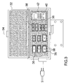
- FIG. 3 is a top view of the housing the present invention.
- FIG. 4 is a perspective view of a generator of the present invention.
- FIG. 5 is a cross-sectional view taken along line 5 — 5 of FIG. 4 of the present invention.
- FIG. 6 is a schematic view of the present invention.
- FIGS. 1 through 6 a new battery charging device embodying the principles and concepts of the present invention and generally designated by the reference numeral 10 will be described.
- the battery charging assembly 10 generally comprises a stationary bike apparatus that includes a frame 12 , a seat 14 attached to the frame 12 and an axle 16 rotatably coupled to the frame 12 .
- Each of a pair of pedals 18 is coupled to the axle 16 .
- An electrical generator 22 is mounted on the frame 12 and is mechanically coupled to the axle 16 so that the generator 22 generates electricity when the axle 16 is rotated.
- the generator 22 may be any common generator such as is often used on stationary bikes for the purpose of powering monitoring equipment on the stationary bike.
- the generator 22 may be coupled to a belt 24 extending between the axle 16 and the generator 22 .
- a housing 26 has a bottom wall 28 and a perimeter wall 30 that is attached to and extends upwardly from the bottom wall 28 .
- a covering 32 is hingedly coupled to an upper edge of the perimeter wall 30 for selectively opening or closing the housing 26 .
- a handle 34 is attached to the covering 32 .
- the housing 26 is positioned adjacent to the seat 14 .
- a plurality of battery cradles 36 is mounted in the housing 26 .
- Each of the battery cradles 36 has a size and shape adapted for receiving and being electrically couplable to a rechargeable battery 38 .
- the battery cradles 36 are each electrically coupled to the generator 22 so that rechargeable batteries 38 mounted in the battery cradles 36 are recharged when the axle 16 is rotated.
- the battery cradles 36 are generally conventional cradles used for recharging rechargeable batteries 38 .
- a phone cradle 40 is mounted in the housing 26 and is adapted for receiving and is electrically coupled to a cellular phone 42 .
- the phone cradle 40 is electrically coupled to the generator 22 so that a cellular phone 42 mounted in the phone cradle 40 is recharged when the axle 16 is rotated.
- the phone cradle 40 like the battery cradles 36 , can be any conventional design and structure adapted for receiving and charging a cellular phone battery.
- a switch 44 is electrically coupled to the generator 22 for selectively turning off electrical current between the generator 22 and the battery 36 and phone 40 cradles.
- the switch 44 is preferably mounted on the frame 12 of the stationary bike on or adjacent to handles 20 attached to the frame 12 .
- a female plug 46 is electrically coupled to the phone 40 and battery 36 cradles for selectively receiving and electrically coupling a male power plug 48 to the battery 36 and phone 40 cradles.
- the female plug 46 allows a person to use a secondary source of electricity to recharge batteries 38 and a cell phone 42 .
- phone 40 and battery 36 cradles are selectively filled with batteries 38 and/or a cellular phone 42 so that those devices may be recharged.
- the cradles 36 , 40 preferably have a variety of sizes for fitting AAA batteries, AA batteries, C batteries, D batteries and 9-volt batteries.
- the user pedals the stationary bike so that the axle 16 rotates and causes the generator 22 to produce electricity.
- the electricity generated in this manner is used to recharge the batteries 38 and cellular phone 42 .
- the batteries 38 and cellular phone 42 are removed from their respective cradles 36 , 40 and used in a conventional manner.
Abstract
A battery charging assembly includes a stationary bike apparatus that includes a frame, a seat attached to the frame and an axle rotatably coupled to the frame. Each of a pair of pedals is coupled to the axle. An electrical generator is mounted on the frame and is mechanically coupled to the axle such that the generator generates electricity when the axle is rotated. A housing has a bottom wall and a perimeter wall that is attached to and extends upwardly from the bottom wall. A plurality of battery cradles is mounted in the housing. Each of the battery cradles has a size and shape for receiving and being electrically couplable to a rechargeable battery. Each of the battery cradles is electrically coupled to the generator so that rechargeable batteries mounted in the battery cradles are recharged when the axle is rotated.
Description
1. Field of the Invention
The present invention relates to battery charging devices and more particularly pertains to a new battery charging device for recharging rechargeable batteries using electricity produced from a stationary bike assembly.
2. Description of the Prior Art
The use of battery charging devices is known in the prior art. U.S. Pat. No. 5,243,224 describes a wheel in which a person may run and which is coupled to a generator for generating electric current when the wheel is rotated. Another type of battery charging device is U.S. Pat. No. 4,555,656 which includes a generator and rechargeable battery assembly for use with a stationary bike. The battery and generator power monitoring equipment and electronics positioned on the electric bike. A similar device is found in U.S. Pat. No. 6,104,096.
While these devices fulfill their respective, particular objectives and requirements, the need remains for a device which utilizes the electricity that may be generated while using a stationary bike for the purpose of recharging rechargeable batteries. The batteries may then be used for powering small electronics. The device may also be used for recharging cellular phones and the like.
The present invention meets the needs presented above by comprising a stationary bike apparatus that includes a frame, a seat attached to the frame and an axle rotatably coupled to the frame. Each of a pair of pedals is coupled to the axle. An electrical generator is mounted on the frame and is mechanically coupled to the axle such that the generator generates electricity when the axle is rotated. A housing has a bottom wall and a perimeter wall that is attached to and extends upwardly from the bottom wall. A plurality of battery cradles is mounted in the housing. Each of the battery cradles has a size and shape for receiving and being electrically couplable to a rechargeable battery. Each of the battery cradles is electrically coupled to the generator so that rechargeable batteries mounted in the battery cradles are recharged when the axle is rotated.
There has thus been outlined, rather broadly, the more important features of the invention in order that the detailed description thereof that follows may be better understood, and in order that the present contribution to the art may be better appreciated. There are additional features of the invention that will be described hereinafter and which will form the subject matter of the claims appended hereto.
The objects of the invention, along with the various features of novelty which characterize the invention, are pointed out with particularity in the claims annexed to and forming a part of this disclosure.
The invention will be better understood and objects other than those set forth above will become apparent when consideration is given to the following detailed description thereof. Such description makes reference to the annexed drawings wherein:
With reference now to the drawings, and in particular to FIGS. 1 through 6 thereof, a new battery charging device embodying the principles and concepts of the present invention and generally designated by the reference numeral 10 will be described.
As best illustrated in FIGS. 1 through 6 , the battery charging assembly 10 generally comprises a stationary bike apparatus that includes a frame 12, a seat 14 attached to the frame 12 and an axle 16 rotatably coupled to the frame 12. Each of a pair of pedals 18 is coupled to the axle 16.
An electrical generator 22 is mounted on the frame 12 and is mechanically coupled to the axle 16 so that the generator 22 generates electricity when the axle 16 is rotated. The generator 22 may be any common generator such as is often used on stationary bikes for the purpose of powering monitoring equipment on the stationary bike. The generator 22 may be coupled to a belt 24 extending between the axle 16 and the generator 22.
A housing 26 has a bottom wall 28 and a perimeter wall 30 that is attached to and extends upwardly from the bottom wall 28. A covering 32 is hingedly coupled to an upper edge of the perimeter wall 30 for selectively opening or closing the housing 26. A handle 34 is attached to the covering 32. The housing 26 is positioned adjacent to the seat 14.
A plurality of battery cradles 36 is mounted in the housing 26. Each of the battery cradles 36 has a size and shape adapted for receiving and being electrically couplable to a rechargeable battery 38. The battery cradles 36 are each electrically coupled to the generator 22 so that rechargeable batteries 38 mounted in the battery cradles 36 are recharged when the axle 16 is rotated. The battery cradles 36 are generally conventional cradles used for recharging rechargeable batteries 38.
A phone cradle 40 is mounted in the housing 26 and is adapted for receiving and is electrically coupled to a cellular phone 42. The phone cradle 40 is electrically coupled to the generator 22 so that a cellular phone 42 mounted in the phone cradle 40 is recharged when the axle 16 is rotated. The phone cradle 40, like the battery cradles 36, can be any conventional design and structure adapted for receiving and charging a cellular phone battery.
A switch 44 is electrically coupled to the generator 22 for selectively turning off electrical current between the generator 22 and the battery 36 and phone 40 cradles. The switch 44 is preferably mounted on the frame 12 of the stationary bike on or adjacent to handles 20 attached to the frame 12.
A female plug 46 is electrically coupled to the phone 40 and battery 36 cradles for selectively receiving and electrically coupling a male power plug 48 to the battery 36 and phone 40 cradles. The female plug 46 allows a person to use a secondary source of electricity to recharge batteries 38 and a cell phone 42.
In use, phone 40 and battery 36 cradles are selectively filled with batteries 38 and/or a cellular phone 42 so that those devices may be recharged. The cradles 36, 40 preferably have a variety of sizes for fitting AAA batteries, AA batteries, C batteries, D batteries and 9-volt batteries. The user pedals the stationary bike so that the axle 16 rotates and causes the generator 22 to produce electricity. The electricity generated in this manner is used to recharge the batteries 38 and cellular phone 42. Once recharged, the batteries 38 and cellular phone 42 are removed from their respective cradles 36, 40 and used in a conventional manner.
With respect to the above description then, it is to be realized that the optimum dimensional relationships for the parts of the invention, to include variations in size, materials, shape, form, function and manner of operation, assembly and use, are deemed readily apparent and obvious to one skilled in the art, and all equivalent relationships to those illustrated in the drawings and described in the specification are intended to be encompassed by the present invention.
Therefore, the foregoing is considered as illustrative only of the principles of the invention. Further, since numerous modifications and changes will readily occur to those skilled in the art, it is not desired to limit the invention to the exact construction and operation shown and described, and accordingly, all suitable modifications and equivalents may be resorted to, falling within the scope of the invention.
Claims (6)
1. A battery charging assembly comprising:
a stationary bike apparatus including a frame, a seat attached to said frame and an axle rotatably coupled to said frame, each of a pair of pedals being coupled to said axle;
an electrical generator being mounted on said frame and being mechanically coupled to said axle such that said generator generates electricity when said axle is rotated;
a housing having a bottom wall and a perimeter wall being attached to and extending upwardly from said bottom wall;
a plurality of battery cradles being mounted in said housing, each of said battery cradles having a size and shape for receiving and being electrically couplable to a rechargeable battery, each of said battery cradles being electrically coupled to said generator such that rechargeable batteries mounted in said battery cradles are recharged when said axle is rotated; and
a phone cradle being mounted in said housing and being adapted for receiving and being electrically coupled to a cellular phone, said phone cradle being electrically coupled to said generator such that a cellular phone mounted in said phone cradle is recharged when said axle is rotated.
2. The battery charging assembly according to claim 1 , further including a covering being hingedly coupled to an upper edge of said perimeter wall for selectively opening or closing said housing.
3. The battery charging assembly according to claim 1 , further including a switch being electrically coupled to said generator for selectively turning off electrical current between said generator and said battery cradles.
4. The battery charging assembly according to claim 3 , further including a female plug being electrically coupled to said phone and battery cradles for selectively receiving and electrically coupling a male power plug to said battery cradles, the male power plug providing electrical power to said battery cradles.
5. The battery charging assembly according to claim 1 , further including a female plug being electrically coupled to said phone and battery cradles for selectively receiving and electrically coupling a male power plug to said battery cradles, the male power plug providing electrical power to said battery cradles.
6. A battery charging assembly comprising:
a stationary bike apparatus including a frame, a seat attached to said frame and an axle rotatably coupled to said frame, each of a pair of pedals being coupled to said axle;
an electrical generator being mounted on said frame and being mechanically coupled to said axle such that said generator generates electricity when said axle is rotated;
a housing having a bottom wall and a perimeter wall being attached to and extending upwardly from said bottom wall, a covering being hingedly coupled to an upper edge of said perimeter wall for selectively opening or closing said housing;
a plurality of battery cradles being mounted in said housing, each of said battery cradles having a size and shape for receiving and being electrically couplable to a rechargeable battery, each of said battery cradles being electrically coupled to said generator such that rechargeable batteries mounted in said battery cradles are recharged when said axle is rotated;
a phone cradle being mounted in said housing and being adapted for receiving and being electrically coupled to a cellular phone, said phone cradle being electrically coupled to said generator such that a cellular phone mounted in said phone cradle is recharged when said axle is rotated;
a switch being electrically coupled to said generator for selectively turning off electrical current between said generator and said battery and phone cradles; and
a female plug being electrically coupled to said phone and battery cradles for selectively receiving and electrically coupling a
male power plug to said battery and phone cradles.
Priority Applications (1)
| Application Number | Priority Date | Filing Date | Title |
|---|---|---|---|
| US11/129,715 US7090620B1 (en) | 2005-05-16 | 2005-05-16 | Battery charging assembly |
Applications Claiming Priority (1)
| Application Number | Priority Date | Filing Date | Title |
|---|---|---|---|
| US11/129,715 US7090620B1 (en) | 2005-05-16 | 2005-05-16 | Battery charging assembly |
Publications (1)
| Publication Number | Publication Date |
|---|---|
| US7090620B1 true US7090620B1 (en) | 2006-08-15 |
Family
ID=36781677
Family Applications (1)
| Application Number | Title | Priority Date | Filing Date |
|---|---|---|---|
| US11/129,715 Expired - Fee Related US7090620B1 (en) | 2005-05-16 | 2005-05-16 | Battery charging assembly |
Country Status (1)
| Country | Link |
|---|---|
| US (1) | US7090620B1 (en) |
Cited By (18)
| Publication number | Priority date | Publication date | Assignee | Title |
|---|---|---|---|---|
| US20070259756A1 (en) * | 2006-05-05 | 2007-11-08 | Kuykendall William E | Method and apparatus for adjusting resistance to exercise |
| US20090054207A1 (en) * | 2007-08-21 | 2009-02-26 | Cell Power Co., Ltd. | Exerciser for generating electricity |
| US20090315336A1 (en) * | 2008-06-23 | 2009-12-24 | Hudson Worthington Harr | Renewable energy generation system |
| US7833135B2 (en) | 2007-06-27 | 2010-11-16 | Scott B. Radow | Stationary exercise equipment |
| US7862476B2 (en) * | 2005-12-22 | 2011-01-04 | Scott B. Radow | Exercise device |
| US20110118086A1 (en) * | 2005-12-22 | 2011-05-19 | Mr. Scott B. Radow | Exercise device |
| US7967734B1 (en) | 2010-04-02 | 2011-06-28 | Mike Damian | Exercise bike and electricity producing combination apparatus |
| DE102010019703A1 (en) * | 2010-05-07 | 2011-11-10 | Otto Olti | Fitness apparatus e.g. training bicycle, for physical operation, has generator converting mechanical energy into electrical energy, and removable, portable battery storing electrical energy and provided with carrying handle |
| US20120010048A1 (en) * | 2009-03-17 | 2012-01-12 | Woodway Usa, Inc. | Power generating manually operated treadmill |
| US20120217758A1 (en) * | 2011-02-24 | 2012-08-30 | Bion Inc. | Acceleration mechanism for exercise equipment |
| WO2013026799A1 (en) * | 2011-08-19 | 2013-02-28 | Wewatt | Furniture for generating green energy |
| US9283421B2 (en) | 2013-03-21 | 2016-03-15 | E. Gen Llc | Stationary exercise equipment power generator |
| US20180361195A1 (en) * | 2017-06-20 | 2018-12-20 | Pixart Imaging Inc. | Detachable speed determining device capableof computing accurate speed information of a bicycle and fixing a bike component of the bicycle |
| US10238911B2 (en) | 2016-07-01 | 2019-03-26 | Woodway Usa, Inc. | Motorized treadmill with motor braking mechanism and methods of operating same |
| US10610725B2 (en) | 2015-04-20 | 2020-04-07 | Crew Innovations, Llc | Apparatus and method for increased realism of training on exercise machines |
| US10709926B2 (en) | 2015-10-06 | 2020-07-14 | Woodway Usa, Inc. | Treadmill |
| USD930089S1 (en) | 2019-03-12 | 2021-09-07 | Woodway Usa, Inc. | Treadmill |
| US11364419B2 (en) | 2019-02-21 | 2022-06-21 | Scott B. Radow | Exercise equipment with music synchronization |
Citations (14)
| Publication number | Priority date | Publication date | Assignee | Title |
|---|---|---|---|---|
| US3904920A (en) | 1973-04-12 | 1975-09-09 | Ronald A Griffith | Safety lighting system |
| US4389047A (en) * | 1981-01-02 | 1983-06-21 | Hall Lawrence W | Rotary exercise device |
| US4555656A (en) * | 1984-01-20 | 1985-11-26 | David Ryan | Generator and rechargeable battery system for pedal powered vehicles |
| US5050865A (en) | 1987-12-28 | 1991-09-24 | Quent Augspurger | Cycle training device |
| US5243224A (en) * | 1990-05-09 | 1993-09-07 | Tagney Jr Lee | Jogging electric current generator |
| USD377672S (en) | 1995-12-19 | 1997-01-28 | Precor Incorporated | Exercise cycle |
| US5616104A (en) * | 1995-08-10 | 1997-04-01 | The United States Of America As Represented By The Administrator Of The National Aeronautics And Space Administration | Human powered centrifuge |
| US5895991A (en) | 1997-05-15 | 1999-04-20 | Sram Deutschland Gmbh | Electric generator for bicycles |
| US6104096A (en) | 1998-02-02 | 2000-08-15 | Pedalite Limited | Electricity generation for pedalled vehicles |
| US6124699A (en) * | 1998-09-11 | 2000-09-26 | Matsushita Electric Industrial, Co., Ltd. | Battery charger device |
| US6229224B1 (en) * | 1999-05-13 | 2001-05-08 | James P. Gagne | Pedal operated power generating system |
| US6260649B1 (en) * | 1999-03-29 | 2001-07-17 | Robert S. Carney, Jr. | Energy conserving electric vehicle |
| US6641952B2 (en) * | 2001-04-20 | 2003-11-04 | Hewlett-Packard Development Company, L.P. | Battery arrangement for reducing battery terminal contact resistance stemming from insulating contaminant layer on same |
| US6717280B1 (en) * | 2000-02-28 | 2004-04-06 | Francis Bienville | Bicycle based emergency battery charging system |
-
2005
- 2005-05-16 US US11/129,715 patent/US7090620B1/en not_active Expired - Fee Related
Patent Citations (14)
| Publication number | Priority date | Publication date | Assignee | Title |
|---|---|---|---|---|
| US3904920A (en) | 1973-04-12 | 1975-09-09 | Ronald A Griffith | Safety lighting system |
| US4389047A (en) * | 1981-01-02 | 1983-06-21 | Hall Lawrence W | Rotary exercise device |
| US4555656A (en) * | 1984-01-20 | 1985-11-26 | David Ryan | Generator and rechargeable battery system for pedal powered vehicles |
| US5050865A (en) | 1987-12-28 | 1991-09-24 | Quent Augspurger | Cycle training device |
| US5243224A (en) * | 1990-05-09 | 1993-09-07 | Tagney Jr Lee | Jogging electric current generator |
| US5616104A (en) * | 1995-08-10 | 1997-04-01 | The United States Of America As Represented By The Administrator Of The National Aeronautics And Space Administration | Human powered centrifuge |
| USD377672S (en) | 1995-12-19 | 1997-01-28 | Precor Incorporated | Exercise cycle |
| US5895991A (en) | 1997-05-15 | 1999-04-20 | Sram Deutschland Gmbh | Electric generator for bicycles |
| US6104096A (en) | 1998-02-02 | 2000-08-15 | Pedalite Limited | Electricity generation for pedalled vehicles |
| US6124699A (en) * | 1998-09-11 | 2000-09-26 | Matsushita Electric Industrial, Co., Ltd. | Battery charger device |
| US6260649B1 (en) * | 1999-03-29 | 2001-07-17 | Robert S. Carney, Jr. | Energy conserving electric vehicle |
| US6229224B1 (en) * | 1999-05-13 | 2001-05-08 | James P. Gagne | Pedal operated power generating system |
| US6717280B1 (en) * | 2000-02-28 | 2004-04-06 | Francis Bienville | Bicycle based emergency battery charging system |
| US6641952B2 (en) * | 2001-04-20 | 2003-11-04 | Hewlett-Packard Development Company, L.P. | Battery arrangement for reducing battery terminal contact resistance stemming from insulating contaminant layer on same |
Cited By (44)
| Publication number | Priority date | Publication date | Assignee | Title |
|---|---|---|---|---|
| US7976434B2 (en) * | 2005-12-22 | 2011-07-12 | Scott B. Radow | Exercise device |
| US7862476B2 (en) * | 2005-12-22 | 2011-01-04 | Scott B. Radow | Exercise device |
| US20110118086A1 (en) * | 2005-12-22 | 2011-05-19 | Mr. Scott B. Radow | Exercise device |
| US20070259756A1 (en) * | 2006-05-05 | 2007-11-08 | Kuykendall William E | Method and apparatus for adjusting resistance to exercise |
| US7833135B2 (en) | 2007-06-27 | 2010-11-16 | Scott B. Radow | Stationary exercise equipment |
| US20090054207A1 (en) * | 2007-08-21 | 2009-02-26 | Cell Power Co., Ltd. | Exerciser for generating electricity |
| US20090315336A1 (en) * | 2008-06-23 | 2009-12-24 | Hudson Worthington Harr | Renewable energy generation system |
| US10799745B2 (en) | 2009-03-17 | 2020-10-13 | Woodway Usa, Inc. | Manual treadmill and methods of operating the same |
| US10265566B2 (en) | 2009-03-17 | 2019-04-23 | Woodway Usa, Inc. | Manual treadmill and methods of operating the same |
| US20120010048A1 (en) * | 2009-03-17 | 2012-01-12 | Woodway Usa, Inc. | Power generating manually operated treadmill |
| US11590377B2 (en) | 2009-03-17 | 2023-02-28 | Woodway Usa, Inc. | Manually powered treadmill |
| US11465005B2 (en) | 2009-03-17 | 2022-10-11 | Woodway Usa, Inc. | Manually powered treadmill |
| US11179589B2 (en) | 2009-03-17 | 2021-11-23 | Woodway Usa, Inc. | Treadmill with electromechanical brake |
| US8864627B2 (en) * | 2009-03-17 | 2014-10-21 | Woodway Usa, Inc. | Power generating manually operated treadmill |
| US10850150B2 (en) | 2009-03-17 | 2020-12-01 | Woodway Usa, Inc. | Manually powered treadmill with variable braking resistance |
| US8986169B2 (en) | 2009-03-17 | 2015-03-24 | Woodway Usa, Inc. | Manual treadmill and methods of operating the same |
| US9039580B1 (en) | 2009-03-17 | 2015-05-26 | Woodway Usa, Inc. | Manual treadmill and methods of operating the same |
| USD736866S1 (en) | 2009-03-17 | 2015-08-18 | Woodway Usa, Inc. | Treadmill |
| US9114276B2 (en) | 2009-03-17 | 2015-08-25 | Woodway Usa, Inc. | Manual treadmill and methods of operating the same |
| US9216316B2 (en) | 2009-03-17 | 2015-12-22 | Woodway Usa, Inc. | Power generating manually operated treadmill |
| US10561884B2 (en) | 2009-03-17 | 2020-02-18 | Woodway Usa, Inc. | Manual treadmill and methods of operating the same |
| USD753245S1 (en) | 2009-03-17 | 2016-04-05 | Woodway Usa, Inc. | Treadmill |
| USD753776S1 (en) | 2009-03-17 | 2016-04-12 | Woodway Usa, Inc. | Treadmill |
| US9956450B2 (en) | 2009-03-17 | 2018-05-01 | Woodway Usa, Inc. | Power generating manually operated treadmill |
| US10561883B2 (en) | 2009-03-17 | 2020-02-18 | Woodway Usa, Inc. | Manually powered treadmill with variable braking resistance |
| US10434354B2 (en) | 2009-03-17 | 2019-10-08 | Woodway Usa, Inc. | Power generating manually operated treadmill |
| US7967734B1 (en) | 2010-04-02 | 2011-06-28 | Mike Damian | Exercise bike and electricity producing combination apparatus |
| DE102010019703A1 (en) * | 2010-05-07 | 2011-11-10 | Otto Olti | Fitness apparatus e.g. training bicycle, for physical operation, has generator converting mechanical energy into electrical energy, and removable, portable battery storing electrical energy and provided with carrying handle |
| US20120217758A1 (en) * | 2011-02-24 | 2012-08-30 | Bion Inc. | Acceleration mechanism for exercise equipment |
| US8939871B2 (en) * | 2011-02-24 | 2015-01-27 | Bion, Inc. | Acceleration mechanism for exercise equipment |
| WO2013026799A1 (en) * | 2011-08-19 | 2013-02-28 | Wewatt | Furniture for generating green energy |
| BE1020193A3 (en) * | 2011-08-19 | 2013-06-04 | Wewatt | GREEN FURNITURE. |
| US9283421B2 (en) | 2013-03-21 | 2016-03-15 | E. Gen Llc | Stationary exercise equipment power generator |
| US10610725B2 (en) | 2015-04-20 | 2020-04-07 | Crew Innovations, Llc | Apparatus and method for increased realism of training on exercise machines |
| US10709926B2 (en) | 2015-10-06 | 2020-07-14 | Woodway Usa, Inc. | Treadmill |
| US11369835B2 (en) | 2015-10-06 | 2022-06-28 | Woodway Usa, Inc. | Configuration of a running surface for a manual treadmill |
| US11826608B2 (en) | 2015-10-06 | 2023-11-28 | Woodway Usa, Inc. | Treadmill with intermediate member |
| US10905914B2 (en) | 2016-07-01 | 2021-02-02 | Woodway Usa, Inc. | Motorized treadmill with motor braking mechanism and methods of operating same |
| US11420092B2 (en) | 2016-07-01 | 2022-08-23 | Woodway Usa, Inc. | Motorized treadmill with motor braking mechanism and methods of operating same |
| US10238911B2 (en) | 2016-07-01 | 2019-03-26 | Woodway Usa, Inc. | Motorized treadmill with motor braking mechanism and methods of operating same |
| US20180361195A1 (en) * | 2017-06-20 | 2018-12-20 | Pixart Imaging Inc. | Detachable speed determining device capableof computing accurate speed information of a bicycle and fixing a bike component of the bicycle |
| US10335633B2 (en) * | 2017-06-20 | 2019-07-02 | Pixart Imaging Inc. | Detachable speed determining device capable of computing accurate speed information of a bicycle and fixing a bike component of the bicycle |
| US11364419B2 (en) | 2019-02-21 | 2022-06-21 | Scott B. Radow | Exercise equipment with music synchronization |
| USD930089S1 (en) | 2019-03-12 | 2021-09-07 | Woodway Usa, Inc. | Treadmill |
Similar Documents
| Publication | Publication Date | Title |
|---|---|---|
| US7090620B1 (en) | Battery charging assembly | |
| US6305185B1 (en) | Cooler device with integrated solar power and stereo system | |
| US6799993B2 (en) | Portable electrical energy source | |
| US7667433B1 (en) | Recharging cover system | |
| US20150207360A1 (en) | Integrated mobile phone case and charger | |
| FR2859865A3 (en) | Rechargeable hearing aid includes battery charger with receiving groove having connection terminals connected to battery chamber, to receive hearing aid structure, and cover to conceal groove | |
| US8415921B1 (en) | Toolbox device | |
| US11811259B2 (en) | Power pack | |
| US20160285304A1 (en) | Portable Solar Power Generator | |
| US7020500B2 (en) | Mobile communication system powered by multiple batteries | |
| US20060082991A1 (en) | Flashlight adaptor for providing alternative direct current power supply to other electronic instruments | |
| US7247954B1 (en) | Portable AC power system | |
| US7015675B1 (en) | Portable power tool and power supply combination | |
| JP2009039841A (en) | Electrical connection device of charging type electric tool | |
| TWM557932U (en) | Mobile charging device and power supply assembly thereof | |
| US10263441B1 (en) | Electronic device case with charging mechanism | |
| US20070236175A1 (en) | Combination battery charger | |
| US7583054B1 (en) | Portable power supply and recharging apparatus | |
| CN210592284U (en) | Motorcycle device with battery convenient to take | |
| CN204976562U (en) | Electric tool structure | |
| CN215647286U (en) | Bluetooth earphone and Bluetooth earphone box | |
| KR200325398Y1 (en) | Portable vibration belt for diet | |
| JP3227427U (en) | Electric bike | |
| JPH08237883A (en) | Battery charger using solar cell | |
| CN201570881U (en) | Portable charging device |
Legal Events
| Date | Code | Title | Description |
|---|---|---|---|
| REMI | Maintenance fee reminder mailed | ||
| LAPS | Lapse for failure to pay maintenance fees | ||
| STCH | Information on status: patent discontinuation |
Free format text: PATENT EXPIRED DUE TO NONPAYMENT OF MAINTENANCE FEES UNDER 37 CFR 1.362 |
|
| FP | Expired due to failure to pay maintenance fee |
Effective date: 20100815 |