US7099396B1 - Multicarrier modulation using weighted prototype functions - Google Patents
Multicarrier modulation using weighted prototype functions Download PDFInfo
- Publication number
- US7099396B1 US7099396B1 US09/446,958 US44695802A US7099396B1 US 7099396 B1 US7099396 B1 US 7099396B1 US 44695802 A US44695802 A US 44695802A US 7099396 B1 US7099396 B1 US 7099396B1
- Authority
- US
- United States
- Prior art keywords
- complex
- coefficients
- values
- samples
- transmitted
- Prior art date
- Legal status (The legal status is an assumption and is not a legal conclusion. Google has not performed a legal analysis and makes no representation as to the accuracy of the status listed.)
- Expired - Fee Related
Links
Images
Classifications
-
- H—ELECTRICITY
- H04—ELECTRIC COMMUNICATION TECHNIQUE
- H04L—TRANSMISSION OF DIGITAL INFORMATION, e.g. TELEGRAPHIC COMMUNICATION
- H04L27/00—Modulated-carrier systems
- H04L27/26—Systems using multi-frequency codes
- H04L27/2601—Multicarrier modulation systems
- H04L27/2626—Arrangements specific to the transmitter only
- H04L27/2627—Modulators
- H04L27/2634—Inverse fast Fourier transform [IFFT] or inverse discrete Fourier transform [IDFT] modulators in combination with other circuits for modulation
-
- H—ELECTRICITY
- H04—ELECTRIC COMMUNICATION TECHNIQUE
- H04L—TRANSMISSION OF DIGITAL INFORMATION, e.g. TELEGRAPHIC COMMUNICATION
- H04L27/00—Modulated-carrier systems
- H04L27/26—Systems using multi-frequency codes
- H04L27/2601—Multicarrier modulation systems
- H04L27/2697—Multicarrier modulation systems in combination with other modulation techniques
- H04L27/2698—Multicarrier modulation systems in combination with other modulation techniques double density OFDM/OQAM system, e.g. OFDM/OQAM-IOTA system
Definitions
- the field of the invention is that of the transmission or broadcasting of digital data, or of analog and sampled data, designed to be received especially by mobiles. More specifically, the invention relates to the implementation of OFDM/OQAM type multicarrier signals. In other words, the invention applies to density 2 or even higher density signals.
- COFDM Coded Orthogonal Frequency Division Multiplexing
- the COFDM technique offers a particularly simple system of equalization, namely the use of a guard interval, also called a cyclical prefix.
- This cyclical prefix provides for robust behaviour in the face of the echoes but at the cost of a relatively major loss of spectral efficiency.
- FR95 05455 Present Document: OFDM/QAM OFDM/QAM/OFDM OFDM/OQAM OFDM/OQAM/NYQUIST OFDM/OMSK OFDM/OQAM/MSK OFDM/IOTA OFDM/OQAM/IOTA
- ⁇ OQAM>> refers to the ⁇ Offset Quadratic Amplitude Modulation>> definition. This expresses the fact that, for such modulations, there is a temporal offset between the transmission of the in-phase part and that of the in-quadrature part of the QAM symbol.
- the invention can be applied in very many fields, especially when high spectral efficiency is sought and when the channel is highly non-stationary.
- a first category of applications relates to terrestrial digital radio-broadcasting, whether of images, sound and/or data.
- the invention can be applied to synchronous broadcasting which intrinsically generates long-term multiple paths. It can also be advantageously applied to broadcasting towards mobile bodies.
- Another category of applications relates to digital radiocommunications.
- the invention can be applied especially in systems of digital communications towards mobiles using high bit rates.
- the transmitted wave undergoes multiple reflections, and the receiver therefore receives a sum of versions delayed by the transmitted signal.
- Each of these versions is attenuated and phase-shifted randomly. Since the receiver is assumed to be in motion, the Doppler effect acts also on each path.
- the transmission band is greater than the coherence band of the channel (the band for the frequency response to the channel may be considered to be constant on a given duration), and fading thus appears in the band, i.e. at a given point in time, certain frequencies are highly attenuated.
- a multicarrier modulation is above all a digital modulation, namely a method for the generation of an electromagnetic signal out of the digital information to be transmitted.
- the originality and value of such a modulation is that it subdivides the limited band allocated to the signal into subbands.
- the channel may be considered to be constant for a duration of transmission of a symbol, chosen to be smaller than the coherence time of the channel.
- the digital information to be transmitted during this period is then distributed over each of these subbands. This has two uses in particular:
- the shaping filter for each of the carriers of the multiplex is the same. It corresponds to the prototype function characterizing the multicarrier modulation.
- the signal transmitted at each instant n ⁇ o , on the m th central frequency subband ⁇ m is a ⁇ m,n e i ⁇ m,n e 2i ⁇ vmt g(t ⁇ nt o ).
- the functions e i ⁇ m,n e 2i ⁇ m ⁇ ot g(t ⁇ n ⁇ o ) are called time-frequency translated functions of g(t).
- g(t) To retrieve the information transmitted by each of the subcarries, it is necessary to choose g(t) so that its time-frequency translated functions are separable. To be sure of this, it is laid down that these translated functions should be orthogonal in the sense of a scalar product defined on all the finite energy functions (which is a Hilbert space in the mathematical sense). This space accepts two possible scalar products, namely:
- OFDM/QAM the function g(t) chosen guarantees and orthogonality of its translated functions in the complex sense (example: OFDM, also called OFDM/QAM/OFDM).
- ⁇ m,n 0 and the data elements ⁇ m,n are complex
- OFDM/OQAM the function g(t) chosen guarantees an orthogonality of its translated functions in the real sense (examples: OFDM/OQAM/NYQUIST, OFDM/OQAM/MSK, OFDM/OQAM/IOTA).
- ⁇ m,n ( ⁇ /2)*(m+n) and the data elements ⁇ m,n are real.
- the real and imaginary parts of a complex function derived from the QAM constellation are transmitted simultaneously at every symbol time T s .
- the invention is designed especially to overcome or reduce these drawbacks. More specifically, a goal of the invention is to provide techniques for the modulation and demodulation of the multicarrier signals that are simple and cost little to implement as compared with the direct approaches.
- each of said carrier frequencies being modulated according to one and the same modulation prototype function g(t) with a truncation length of 2L ⁇ o ,
- the method comprising, at each symbol time, the following steps:
- the data elements to be processed are stored after weighting and not before. It is thus possible to reduce the memory capacity needed as well as the number of operations performed.
- the samples to be transmitted are built gradually in each field of storage. Accordingly to one advantageous embodiment of the invention, a sample to be transmitted at the instant j ⁇ o +k ⁇ o /M, referenced s k+jm is written as follows:
- C oj to C 2M-1j are the 2M complex coefficients generated between the instants j ⁇ o and (j+1) ⁇ o ;
- ⁇ k,q and ⁇ k,q are said weighting coefficients.
- the method comprises, for the generation of a symbol with an index j formed by M samples, the following steps:
- each sending step may be followed by a step for the updating of said memory locations comprising:
- said coefficients representing data elements to be transmitted are obtained by the implementation of a mathematical transform comprising the following steps:
- the invention also relates to the modulation devices implementing a modulation method of this kind.
- this device comprises especially:
- N complex multipliers working at the rate N ⁇ o /2LM, N being equal to 1, 2, 4, . . . or 2L.
- a method for the demodulation of a received signal corresponding to a multicarrier emitted signal with a density 1/( ⁇ o . ⁇ o ) 2.
- the 2M complex values derived from the temporal aliasing step between the instants (j+2L ⁇ 1) ⁇ o and (j+2L) ⁇ o are written as follows:
- r k′+(j+q′)M represents the sample received at the instant k′ ⁇ o +(j+q′) ⁇ o /M;
- ⁇ ′ k,q and ⁇ ′ k,q are said weighting coefficients.
- said processing step comprises the following steps:
- said steps are implemented at the rate ⁇ o /M of the samples.
- the invention also relates to the demodulation devices implementing this method. These devices comprise:
- temporal aliasing means summing up L weighting results so as to obtain 2M complex values
- storage means comprising 2ML-M simultaneous write/read RAM type complex memory locations
- N complex multipliers working at the N ⁇ o /2LM rate, where N is equal to 1, 2, 4 . . . or 2L;
- the invention more generally relates to a filtering method delivering series of M complex output values at regular intervals from 2L series of 2M complex input values
- filtering must of course be taken here in its general sense of processing or computation performed on data elements. This processing which comprises the computation of a weighted sum is done gradually.
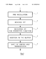
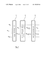
- FIG. 1 gives a general and simplified illustration of the method of modulation of the invention (step j) used to generate M samples;
- FIGS. 2 a , 2 b and 2 c are closer views of portions of FIG. 2 , broken out as indicated by the lines on FIG. 2 .
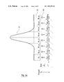
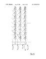
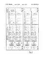
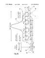
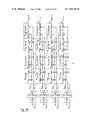
- FIG. 3 gives a more detailed illustration of the working of the method of modulation of the invention for the instances j ⁇ 1 to j+2;
- FIGS. 3 a , 3 b , 3 c and 3 d are closer views of portions of FIG. 3 , broken out as indicated by the lines on FIG. 3 .
- FIGS. 4 a and 4 b are closer views of portions of FIG. 4 , broken out as indicated by the lines of FIG. 4 .
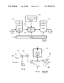
- FIG. 5 is a schematic diagram of a complex IFFT circuit known per se
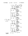
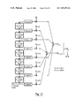
- FIGS. 6A to 6C illustrate the optimized architectures implementing FIFO systems and respectively using a single multiplier ( FIG. 6A ), L multipliers ( FIG. 6B ) or 2L multipliers ( FIG. 6C );
- FIG. 7 shows an optimized embodiment of the reverse FFT using a real input FFT
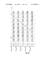
- FIGS. 8 a , 8 b and 8 c are closer views of portions of FIG. 8 , broken out as indicated by the lines on FIG. 8 .
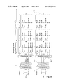
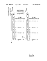
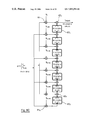
- FIG. 9 shows the general case of demodulation deduced directly from FIG. 8 ;
- FIG. 10 illustrates a corresponding demodulator architecture
- FIGS. 11 to 12 show two modes of implementation of the reception filtering in the case of a FIFO structure respectively using L and 2L multipliers.
- Intercarrier spacing ⁇ o .
- Length of truncation of the protocol function 2L ⁇ o .
- the prototype function is the temporal support and/or infinite sequential support.
- this function must be truncated.
- the prototype function g(t), the emitted signal s(t) and the emitted signal r(t) may be substituted for x(t).
- filtering is understood to mean an operation of weighting of the results of 2L reverse FFT operations by certain values of the prototype function, followed by an operation of summing of these weighted coefficients. In other words, this is a linear combination.
- the second mode is optimal and is more precisely the object of the invention.
- the modulation algorithm therefore comprises the following main steps:
- the requisite memory size is therefore:
- the prototype function is chosen to be symmetrical, on the 2ML weighting coefficients, and only the ML+1 values are distinct).
- This first procedure reveals a waste of RAM type memory.
- the second architecture proposed shows that it is possible to reduce the size of the necessary RAM by more than half. This reduction is accompanied by a reduction in the number of operations and therefore an increase in the processing speed.
- Equation (10) expresses the construction of M complex values from 2ML complex values. It can be written more generally:
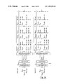
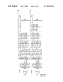
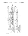
- step j To generate M samples according to this modulation algorithm, it is therefore possible to proceed as illustrated in FIG. 1 (step j):
- Reverse Fourier transform 12 of the 2M complex data elements thus obtained so as to generate C kj and C k+Mj .
- a weighting 13 (corresponding to the application of the prototype function) of the result of the reverse Fourier transform by the prototype function: L parallel weighting operations.
- the L weighting vectors with a size 2M, have the following coefficients:
- a sample of the signal to be transmitted represents a sum of 2L weighted IFFT results.
- the 2ML elements coming from the L parallel weighting operations are herein added to the 2ML elements of the buffer.
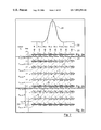
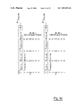
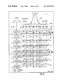
- Each line illustrates the situation of the construction buffer of the data elements to be transmitted, at a given instant. It is necessary to have 2L consecutive symbol times to gradually construct a sample to be transmitted.
- the waveform 2L shown corresponds to the Iota function. It is represented by the 2L vectors of coefficients 22 [g k ] to [g k+7m ], where the index k varies from 0 to M ⁇ 1.
- the 2M coefficients at input are multiplied (23) by the coefficients 22 and then added up (24) each to a partial sum.
- the M partial sums complemented at the step 15 are transmitted, the contents of the buffer are shifted by M memory slots (so as to ensure the right order of computation of the next M samples) and M zeros are inserted in the M vacant memory slots.
- the diagonal 25 thus illustrates the computation of S k+jM .
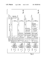
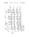
- FIG. 3 give a more detailed view of the working of this algorithm for the instants j ⁇ 1 to j+2.
- the coefficient a mj to be transmitted supplies the pre-modulation module 31 , which gives the reverse FFT 32 the coefficients c mj .
- the reverse FFT delivers the C kj and C k+Mj values (the index k varies from 0 to M ⁇ 1) subjected to the weighting 33 (the weighting operations in parallel) to deliver the results 34 which are summed up in an output buffer 35 .
- FIG. 3 gives an indication of the exact contents of these output buffers.
- the architecture of the modulator corresponding to the above algorithm presented here above must therefore comprise:
- the weighting operations will be made parallel by using L RAMs with a size 2M associated with L multipliers or even 2L RAMs with a size of M complex values associated with 2L multipliers instead of one RAM with 2ML complex values.
- the complexity of the modulation circuit is therefore:
- results indicated in the following table relate to a conventional complex IFFT circuit whose schematic diagram is given in FIG. 5 . It comprises an input buffer 51 , receiving 2M inputs, a computation unit 52 supplied by coefficients stored in the ROM type memory 53 and computed values stored in a RAM type memory 54 that deliver 2M outputs.
- a control module drives these different elements.
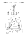
- an additional gain in memory space may be obtained. It is indeed possible to use only (2L ⁇ 1) RAMs with M complex values (total storage: 2ML ⁇ M complex values instead of 2ML). To do this, at the step j, a reading is done of the M samples to be transmitted into the corresponding RAM gradually, and the M complex values C k+Mj g k+(2L ⁇ 1)M are written progressively at the same addresses. To carry out this filtering operation, it is possible, as required, to use RAMs or FIFOs.
- FIGS. 6A to 6C illustrate this method in the case where a FIFO structure is chosen.
- a single multiplier 61 is implemented. It multiplies data elements delivered by the reverse FFT by the weighting coefficients and supplies an adder 62 that also receives the output of the FIFO memory 63 containing 2ML ⁇ M complex values. This FIFO 63 is supplied by the result of the addition 62 .
- a control module 64 enables the output of the FIFO to be directed outwards to deliver the M complex values ready to be transmitted 65 .
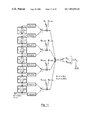
- N 1,2,4, . . . 2L.
- Each of them supplies an adder 62 1 to 62 4 which also receives data elements from the 2L FIFO memories 63 1 to 63 7 each comprising M complex values.
- the FIFO memory 63 1 delivers the M complex outputs.
- Selection means 66 enable the selection of a FIFO memory to be taken into account at each point in time.
- the 2L FIFO memories 63 1 to 63 7 are each supplied by a multiplier 61 1 to 61 8 , associated with its own weighting coefficient and associated with an adder 62 1 to 62 8 .
- the algorithm used to obtain the reverse FFT arranges its output in the optimum order C oj ,C Mj ,C lj ,C M+1j , . . . , C 2M ⁇ 1 and works at the rate ⁇ o /(2M).
- C oj ,C 1j ,C 2M ⁇ 2j ,C 2M ⁇ 1j the proposed gain in memory due to this simultaneous reading and writing of the output buffer then requires the reordering of the outputs of the reverse FFT in the optimum order which requires a storage at output of the FFT. In either case, the gain in memory will be negligible or even zero.
- phase-shifting the inputs x m of an FFT with a size 2M, by i m amounts to applying a circular permutation to its outputs y k by M/2 leftwards.
- An algorithm of this kind enables a reduction by half of the memory space needed for the FFT as well as the number of operations.
- FIG. 5 shows these three operations.
- ⁇ m , j ⁇ e ⁇ [ 1 ⁇ m , j ⁇ e - i ⁇ ⁇ ⁇ m , j ⁇ ⁇ r ⁇ ( t ) ⁇ g m , j * ⁇ ( t ) ⁇ d t ] ( 12 )
- this technique is independent of the way in which the signal has been constructed at transmission. It can be applied to the reception of any type of OFDM/OQAM multicarrier signal.
- r k + jM + 2 ⁇ qM r k ′ + jM + 2 ⁇ qM ⁇ 1 ⁇ k ⁇ ⁇ 0 , ... ⁇ , M - 1 ⁇ ⁇ ⁇ + r ( k ′ + M ) + jM + 2 ⁇ qM ⁇ 1 ⁇ k ⁇ ⁇ M , ... ⁇ , 2 ⁇ M - 1 ⁇ ⁇ ⁇ ⁇ with ⁇ ⁇ ⁇ 0 ⁇ k ⁇ 2 ⁇ M - 1 0 ⁇ k ′ ⁇ M - 1 ( 15.1 )
- g k + jM + 2 ⁇ qM g k ′ + jM + 2 ⁇ qM ⁇ 1 ⁇ k ⁇ ⁇ 0 , ... ⁇ , M - 1 ⁇ ⁇ + g ( k ′ + jM ) + 2 ⁇ qM ⁇ 1 ⁇ k ⁇ ⁇ M , ... ⁇ , 2 ⁇ M - 1 ⁇ ⁇ ⁇ ⁇ with ⁇ ⁇ 0 ⁇ k ⁇ 2 ⁇ M - 1 0 ⁇ k ′ ⁇ 2 ⁇ M - 1 ( 15.2 )
- the estimation of the data elements sent will start after a delay of (2L ⁇ 1) ⁇ o . It is necessary indeed that all the received samples comprising the data element a mj should be stored in the input buffer before â m,j , is computed.
- R k ′ , 1 ⁇ r k ′ + M ⁇ g k ′ + + r k ′ + 3 ⁇ M ⁇ g k ′ + 2 ⁇ M + + r k ′ + 5 ⁇ M ⁇ g k ′ + 4 ⁇ M + ⁇ + r k ′ + 7 ⁇ M ⁇ g k ′ + 6 ⁇ M R ⁇ .
- the general case is illustrated by FIG. 9 and is deduced directly from FIG. 8 .
- the M samples 81 received at an given point in time are stored in an input buffer 82 .
- the data elements contained in this buffer 82 are multiplied (83) by the weighting coefficients 84 representing the waveform 85 (IOTA in the example) then added up (86) to carry out the aliasing.
- the corresponding data elements R kjj supply the FFT 87 , performed on 2M complex samples. Then a phase correction 88 is done and then an extraction 89 of the real part.
- FIG. 8 presents the contents of this buffer for eight successive instants, corresponding to the production of the outputs â mj áâmj+ 7 .
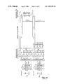
- FIG. 10 illustrates the architecture proposed.
- the input buffer capable of containing 2ML complex values, receives M samples at each ⁇ o .
- the weighting by the prototype function is done by the multiplication operations 102 and then the aliasing is done by means of two adders 103 1 and 103 2 , which supply a buffer 104 of 2M values supplying the complex FFT 105 .
- a phase and amplitude correction 106 is performed and then the real part is selected at 107 to give the 2M real values transmitted.
- FIGS. 11 and 12 implement this method in the case of a FIFO structure.
- the algorithm used to achieve the FFT works at the rate ⁇ o )/(2M) with the inputs arriving in the ⁇ optimum>> order R oj ,R mj ,R lj ,R M+1j , . . . , R M ⁇ 1j ,R 2m ⁇ 1j . If not, a storage at the input of the FFT will be necessary and the memory gain will then be negligible or even zero,
Abstract
Description
| FR95 05455: | Present Document: | ||
| OFDM/QAM | OFDM/QAM/OFDM | ||
| OFDM/OQAM | OFDM/OQAM/NYQUIST | ||
| OFDM/OMSK | OFDM/OQAM/MSK | ||
| OFDM/IOTA | OFDM/OQAM/IOTA | ||
Thus two type of multicarrier modulation are defined:
Accordingly to one advantageous embodiment of the invention, a sample to be transmitted at the instant jτo+kτo/M, referenced sk+jm is written as follows:
where:
-
- αk,q=0 for q as an odd parity number;
- βk,q=0 for q as an even parity number.
The number of operations performed is therefore further reduced by half.
where:
the equation (7) becomes:
| Addition | Multiplication | ||||
| Modu- | Operations | Operations | RAM | ROM | FIFO |
| lation | (real) | (real) | (real) | (real) | (real) |
| Pre-modu- | x | x | x | x | |
| lation | |||||
| Reverse | |||||
| 6 M(1 + log2 M) | 4 M(1 + log2 M) | 8 |
2 M | x | |
| | |||||
| Filtering | |||||
| 4 |
4 |
4 ML | ML + 1 | x | |
(amnim+n(−1)m(n+L))
followed by the complex reverse FFT can be done as illustrated in
of the received signal, the demodulation function then becomes:
going from 0 to 2M−1.
Claims (19)
Applications Claiming Priority (2)
| Application Number | Priority Date | Filing Date | Title |
|---|---|---|---|
| FR9708547A FR2765757B1 (en) | 1997-07-01 | 1997-07-01 | METHOD AND DEVICE FOR MODULATING A MULTI-PORTER SIGNAL OF THE OFDM / OQAM TYPE, AND CORRESPONDING METHOD AND DEVICE FOR DEMODULATION |
| PCT/FR1998/001398 WO1999001967A1 (en) | 1997-07-01 | 1998-06-30 | Multicarrier modulation using weighted prototype functions |
Publications (1)
| Publication Number | Publication Date |
|---|---|
| US7099396B1 true US7099396B1 (en) | 2006-08-29 |
Family
ID=9508910
Family Applications (1)
| Application Number | Title | Priority Date | Filing Date |
|---|---|---|---|
| US09/446,958 Expired - Fee Related US7099396B1 (en) | 1997-07-01 | 1998-06-30 | Multicarrier modulation using weighted prototype functions |
Country Status (6)
| Country | Link |
|---|---|
| US (1) | US7099396B1 (en) |
| EP (1) | EP1005748B1 (en) |
| DE (1) | DE69822641T2 (en) |
| FR (1) | FR2765757B1 (en) |
| NO (1) | NO996575D0 (en) |
| WO (1) | WO1999001967A1 (en) |
Cited By (6)
| Publication number | Priority date | Publication date | Assignee | Title |
|---|---|---|---|---|
| US20080260061A1 (en) * | 2005-05-03 | 2008-10-23 | France Telecom | Method for the Coding of an Ofdm/Oqam Signal Using Symbols with Complex Values, and Corresponding Signal, Devices and Computer Programs |
| US7609611B1 (en) | 1999-09-29 | 2009-10-27 | France Telecom | Method for transmitting an offset modulated biorthogonal multicarrier signal (BFDM/OM) |
| CN103583024A (en) * | 2011-02-28 | 2014-02-12 | 奥兰治 | Method for modulating an OQAM multi-carrier signal, and corresponding computer program and modulator |
| US20150092885A1 (en) * | 2012-04-05 | 2015-04-02 | Interdigital Patent Holdings, Inc. | Systems and methods for providing and/or using an ofdn-oqam structure |
| US10594531B2 (en) * | 2016-02-09 | 2020-03-17 | Technische Universität München | Filter banks and methods for operating filter banks |
| US10999115B2 (en) * | 2017-12-14 | 2021-05-04 | Orange | Method for generating a multicarrier signal, demodulation method, computer program product and corresponding devices |
Families Citing this family (1)
| Publication number | Priority date | Publication date | Assignee | Title |
|---|---|---|---|---|
| EP2174440A2 (en) * | 2007-08-03 | 2010-04-14 | BARTELS, Oliver | Radio device with new cifdm modulation method |
Citations (5)
| Publication number | Priority date | Publication date | Assignee | Title |
|---|---|---|---|---|
| US4792943A (en) * | 1986-03-26 | 1988-12-20 | Ant Nachrichtentechnik Gmbh | Digital filter bank |
| EP0668679A2 (en) | 1994-02-22 | 1995-08-23 | ITALTEL SOCIETA ITALIANA TELECOMUNICAZIONI s.p.a. | OFDM system |
| US5636246A (en) * | 1994-11-16 | 1997-06-03 | Aware, Inc. | Multicarrier transmission system |
| US5671168A (en) * | 1995-07-06 | 1997-09-23 | Technion Research & Development Foundation Ltd. | Digital frequency-domain implementation of arrays |
| US5838268A (en) * | 1997-03-14 | 1998-11-17 | Orckit Communications Ltd. | Apparatus and methods for modulation and demodulation of data |
-
1997
- 1997-07-01 FR FR9708547A patent/FR2765757B1/en not_active Expired - Lifetime
-
1998
- 1998-06-30 US US09/446,958 patent/US7099396B1/en not_active Expired - Fee Related
- 1998-06-30 EP EP98935065A patent/EP1005748B1/en not_active Expired - Lifetime
- 1998-06-30 DE DE69822641T patent/DE69822641T2/en not_active Expired - Lifetime
- 1998-06-30 WO PCT/FR1998/001398 patent/WO1999001967A1/en active IP Right Grant
-
1999
- 1999-12-30 NO NO996575A patent/NO996575D0/en unknown
Patent Citations (5)
| Publication number | Priority date | Publication date | Assignee | Title |
|---|---|---|---|---|
| US4792943A (en) * | 1986-03-26 | 1988-12-20 | Ant Nachrichtentechnik Gmbh | Digital filter bank |
| EP0668679A2 (en) | 1994-02-22 | 1995-08-23 | ITALTEL SOCIETA ITALIANA TELECOMUNICAZIONI s.p.a. | OFDM system |
| US5636246A (en) * | 1994-11-16 | 1997-06-03 | Aware, Inc. | Multicarrier transmission system |
| US5671168A (en) * | 1995-07-06 | 1997-09-23 | Technion Research & Development Foundation Ltd. | Digital frequency-domain implementation of arrays |
| US5838268A (en) * | 1997-03-14 | 1998-11-17 | Orckit Communications Ltd. | Apparatus and methods for modulation and demodulation of data |
Non-Patent Citations (2)
| Title |
|---|
| XP-000304924; Orthogonal Multiple Carrier Data Transmission; Norbert J. Fliege; May-Jun. 1992; pp. 255-264. |
| XP-000577280; Multirate Extensions to Cossap and Lessons Learnt from Developing Advanced Models; 1993; G.R. Danesfahani, T.G. Jeans, Professor B.G. Evans; pp. 1-6. |
Cited By (10)
| Publication number | Priority date | Publication date | Assignee | Title |
|---|---|---|---|---|
| US7609611B1 (en) | 1999-09-29 | 2009-10-27 | France Telecom | Method for transmitting an offset modulated biorthogonal multicarrier signal (BFDM/OM) |
| US20080260061A1 (en) * | 2005-05-03 | 2008-10-23 | France Telecom | Method for the Coding of an Ofdm/Oqam Signal Using Symbols with Complex Values, and Corresponding Signal, Devices and Computer Programs |
| US7961805B2 (en) * | 2005-05-03 | 2011-06-14 | France Telecom | Method for the coding of an OFDM/OQAM signal using symbols with complex values, and corresponding signal, devices and computer programs |
| CN103583024A (en) * | 2011-02-28 | 2014-02-12 | 奥兰治 | Method for modulating an OQAM multi-carrier signal, and corresponding computer program and modulator |
| US9166858B2 (en) | 2011-02-28 | 2015-10-20 | Orange | Method for modulating an OQAM type multi-carrier signal, and corresponding computer program and modulator |
| CN103583024B (en) * | 2011-02-28 | 2016-11-02 | 奥兰治 | For the method that OQAM type multi-carrier signal is modulated and the manipulator of correspondence |
| US20150092885A1 (en) * | 2012-04-05 | 2015-04-02 | Interdigital Patent Holdings, Inc. | Systems and methods for providing and/or using an ofdn-oqam structure |
| US9531575B2 (en) * | 2012-04-05 | 2016-12-27 | Interdigital Patent Holdings, Inc. | Systems and methods for providing and/or using an OFDN-OQAM structure |
| US10594531B2 (en) * | 2016-02-09 | 2020-03-17 | Technische Universität München | Filter banks and methods for operating filter banks |
| US10999115B2 (en) * | 2017-12-14 | 2021-05-04 | Orange | Method for generating a multicarrier signal, demodulation method, computer program product and corresponding devices |
Also Published As
| Publication number | Publication date |
|---|---|
| NO996575D0 (en) | 1999-12-30 |
| FR2765757A1 (en) | 1999-01-08 |
| EP1005748A1 (en) | 2000-06-07 |
| DE69822641D1 (en) | 2004-04-29 |
| FR2765757B1 (en) | 1999-09-17 |
| EP1005748B1 (en) | 2004-03-24 |
| WO1999001967A1 (en) | 1999-01-14 |
| DE69822641T2 (en) | 2005-02-24 |
Similar Documents
| Publication | Publication Date | Title |
|---|---|---|
| EP0836303B1 (en) | Method and apparatus for reduction of peak to average power ratio | |
| EP0839423B1 (en) | Pulse shaping for multicarrier modulation | |
| US7411894B2 (en) | Apparatus and method for guard interval inserting/removing in an OFDM communication system | |
| US7693034B2 (en) | Combined inverse fast fourier transform and guard interval processing for efficient implementation of OFDM based systems | |
| KR100263372B1 (en) | Coarse frequency acquistion method and thereof appratus for orthogonal frequency division multiplexing systems | |
| US11075681B2 (en) | Communication system and method using layered construction of arbitrary unitary matrices | |
| US20080310531A1 (en) | Robust channel estimation in communication systems | |
| US11025470B2 (en) | Communication system and method using orthogonal frequency division multiplexing (OFDM) with non-linear transformation | |
| EP2334020A1 (en) | Wireless communication system | |
| KR100899747B1 (en) | Method and apparatus for reducing peak-to-average power ratio in orthogonal frequency division multiplexing system | |
| US7272188B2 (en) | Distributed pilot multicarrier signal designed to limit interference affecting said pilots | |
| US6584068B1 (en) | Prototype signals construction for multicarrier transmission | |
| US10057097B2 (en) | Modulation method and device delivering a multicarrier signal, and corresponding demodulation method and device and computer program | |
| US10148479B2 (en) | OFDM transmitter with filter banks and corresponding transmission/reception system | |
| EP0833484A1 (en) | Device and method for vector equalization of an OFDM signal | |
| JP3539522B2 (en) | Orthogonal frequency division multiplexed signal transmission method, and transmitter and receiver thereof | |
| US7099396B1 (en) | Multicarrier modulation using weighted prototype functions | |
| US20080037686A1 (en) | Wireless transmission method using ofdm and transmitter and receiver thereof | |
| WO1996001535A1 (en) | Hierarchical ofdm | |
| EP0735712A2 (en) | Multicarrier modulation receiver using remodulation | |
| US7804764B2 (en) | Transmitter and receiver | |
| US20170310525A1 (en) | A method for transmitting a multi-carrier signal, a receiving method, devices, and associated computer programs | |
| KR20070113349A (en) | Apparatus for demodulating broadcasting signal and method for transmitting and receiving broadcasting signal | |
| JP3541526B2 (en) | Frequency division multiplex signal generation method and decoding method | |
| KR100230847B1 (en) | Orthogonal frequency division multiplexing receiving system |
Legal Events
| Date | Code | Title | Description |
|---|---|---|---|
| AS | Assignment |
Owner name: FRANCE TELECOM, FRANCE Free format text: ASSIGNMENT OF ASSIGNORS INTEREST;ASSIGNORS:COMBELLES, PIERRE;LACROIX, DOMINIQUE;REEL/FRAME:011236/0785;SIGNING DATES FROM 20000103 TO 20000125 Owner name: TELEDIFFUSION DE FRANCE, FRANCE Free format text: ASSIGNMENT OF ASSIGNORS INTEREST;ASSIGNORS:COMBELLES, PIERRE;LACROIX, DOMINIQUE;REEL/FRAME:011236/0785;SIGNING DATES FROM 20000103 TO 20000125 |
|
| AS | Assignment |
Owner name: FRANCE TELECOM, FRANCE Free format text: ASSIGNMENT OF ASSIGNORS INTEREST;ASSIGNORS:COMBELLES, PIERRE;LA CROIX, DOMINQUE;JALALI, ALI;REEL/FRAME:013934/0371;SIGNING DATES FROM 20000103 TO 20021011 Owner name: TELEDIFFUSION DE FRANCE, FRANCE Free format text: ASSIGNMENT OF ASSIGNORS INTEREST;ASSIGNORS:COMBELLES, PIERRE;LA CROIX, DOMINQUE;JALALI, ALI;REEL/FRAME:013934/0371;SIGNING DATES FROM 20000103 TO 20021011 |
|
| FEPP | Fee payment procedure |
Free format text: PAYOR NUMBER ASSIGNED (ORIGINAL EVENT CODE: ASPN); ENTITY STATUS OF PATENT OWNER: LARGE ENTITY |
|
| FPAY | Fee payment |
Year of fee payment: 4 |
|
| FPAY | Fee payment |
Year of fee payment: 8 |
|
| FEPP | Fee payment procedure |
Free format text: MAINTENANCE FEE REMINDER MAILED (ORIGINAL EVENT CODE: REM.) |
|
| LAPS | Lapse for failure to pay maintenance fees |
Free format text: PATENT EXPIRED FOR FAILURE TO PAY MAINTENANCE FEES (ORIGINAL EVENT CODE: EXP.); ENTITY STATUS OF PATENT OWNER: LARGE ENTITY |
|
| STCH | Information on status: patent discontinuation |
Free format text: PATENT EXPIRED DUE TO NONPAYMENT OF MAINTENANCE FEES UNDER 37 CFR 1.362 |
|
| FP | Lapsed due to failure to pay maintenance fee |
Effective date: 20180829 |