US7150512B2 - Cleaning system for a continuous ink jet printer - Google Patents
Cleaning system for a continuous ink jet printer Download PDFInfo
- Publication number
- US7150512B2 US7150512B2 US10/871,642 US87164204A US7150512B2 US 7150512 B2 US7150512 B2 US 7150512B2 US 87164204 A US87164204 A US 87164204A US 7150512 B2 US7150512 B2 US 7150512B2
- Authority
- US
- United States
- Prior art keywords
- solvent
- ink
- print head
- orifice
- front face
- Prior art date
- Legal status (The legal status is an assumption and is not a legal conclusion. Google has not performed a legal analysis and makes no representation as to the accuracy of the status listed.)
- Active, expires
Links
Images


Classifications
-
- B—PERFORMING OPERATIONS; TRANSPORTING
- B41—PRINTING; LINING MACHINES; TYPEWRITERS; STAMPS
- B41J—TYPEWRITERS; SELECTIVE PRINTING MECHANISMS, i.e. MECHANISMS PRINTING OTHERWISE THAN FROM A FORME; CORRECTION OF TYPOGRAPHICAL ERRORS
- B41J2/00—Typewriters or selective printing mechanisms characterised by the printing or marking process for which they are designed
- B41J2/005—Typewriters or selective printing mechanisms characterised by the printing or marking process for which they are designed characterised by bringing liquid or particles selectively into contact with a printing material
- B41J2/01—Ink jet
- B41J2/135—Nozzles
- B41J2/165—Preventing or detecting of nozzle clogging, e.g. cleaning, capping or moistening for nozzles
- B41J2/16517—Cleaning of print head nozzles
- B41J2/16552—Cleaning of print head nozzles using cleaning fluids
-
- B—PERFORMING OPERATIONS; TRANSPORTING
- B41—PRINTING; LINING MACHINES; TYPEWRITERS; STAMPS
- B41J—TYPEWRITERS; SELECTIVE PRINTING MECHANISMS, i.e. MECHANISMS PRINTING OTHERWISE THAN FROM A FORME; CORRECTION OF TYPOGRAPHICAL ERRORS
- B41J2/00—Typewriters or selective printing mechanisms characterised by the printing or marking process for which they are designed
- B41J2/005—Typewriters or selective printing mechanisms characterised by the printing or marking process for which they are designed characterised by bringing liquid or particles selectively into contact with a printing material
- B41J2/01—Ink jet
- B41J2/135—Nozzles
- B41J2/165—Preventing or detecting of nozzle clogging, e.g. cleaning, capping or moistening for nozzles
-
- B—PERFORMING OPERATIONS; TRANSPORTING
- B41—PRINTING; LINING MACHINES; TYPEWRITERS; STAMPS
- B41J—TYPEWRITERS; SELECTIVE PRINTING MECHANISMS, i.e. MECHANISMS PRINTING OTHERWISE THAN FROM A FORME; CORRECTION OF TYPOGRAPHICAL ERRORS
- B41J2/00—Typewriters or selective printing mechanisms characterised by the printing or marking process for which they are designed
- B41J2/005—Typewriters or selective printing mechanisms characterised by the printing or marking process for which they are designed characterised by bringing liquid or particles selectively into contact with a printing material
- B41J2/01—Ink jet
- B41J2/17—Ink jet characterised by ink handling
- B41J2/1714—Conditioning of the outside of ink supply systems, e.g. inkjet collector cleaning, ink mist removal
-
- B—PERFORMING OPERATIONS; TRANSPORTING
- B41—PRINTING; LINING MACHINES; TYPEWRITERS; STAMPS
- B41J—TYPEWRITERS; SELECTIVE PRINTING MECHANISMS, i.e. MECHANISMS PRINTING OTHERWISE THAN FROM A FORME; CORRECTION OF TYPOGRAPHICAL ERRORS
- B41J2/00—Typewriters or selective printing mechanisms characterised by the printing or marking process for which they are designed
- B41J2/005—Typewriters or selective printing mechanisms characterised by the printing or marking process for which they are designed characterised by bringing liquid or particles selectively into contact with a printing material
- B41J2/01—Ink jet
- B41J2/17—Ink jet characterised by ink handling
- B41J2/18—Ink recirculation systems
- B41J2/185—Ink-collectors; Ink-catchers
-
- B—PERFORMING OPERATIONS; TRANSPORTING
- B41—PRINTING; LINING MACHINES; TYPEWRITERS; STAMPS
- B41J—TYPEWRITERS; SELECTIVE PRINTING MECHANISMS, i.e. MECHANISMS PRINTING OTHERWISE THAN FROM A FORME; CORRECTION OF TYPOGRAPHICAL ERRORS
- B41J2/00—Typewriters or selective printing mechanisms characterised by the printing or marking process for which they are designed
- B41J2/005—Typewriters or selective printing mechanisms characterised by the printing or marking process for which they are designed characterised by bringing liquid or particles selectively into contact with a printing material
- B41J2/01—Ink jet
- B41J2/135—Nozzles
- B41J2/165—Preventing or detecting of nozzle clogging, e.g. cleaning, capping or moistening for nozzles
- B41J2/16517—Cleaning of print head nozzles
- B41J2002/16567—Cleaning of print head nozzles using ultrasonic or vibrating means
Definitions
- Embodiments of the present invention generally relate to a print head for an ink jet printer, and more particularly to an ink jet printer having a system for cleaning the nozzle and the catcher.
- Conventional continuous ink jet printers supply electrically conductive ink under pressure to a drop generator, which has an orifice or orifices (nozzles) that are typically arranged in a linear array.
- the ink discharges from each orifice in the form of a filament, which subsequently breaks up into a droplet stream.
- Individual droplets in the stream are selectively charged in the region of the break off from the filament, and these charged drops are then deflected as desired by an electrostatic field.
- the deflected drops may proceed to a print receiving medium, whereas undeflected drops are caught in a gutter or catcher and recirculated.
- ink around the orifices dries up, often partially blocking, and sometimes completely clogging, the outer openings to the orifices. Furthermore, during a long shut down period, such as an entire day or weekend, the dried ink may form a block within the orifice or passages attached to the orifice, depending on the type of ink.
- print head cleaning systems and methods are limited to the nozzle, or drop generator.
- ink deposits and residue also accumulate around the catcher, for example. Ink droplets often settle on and within the catcher. As ink deposits and residue accumulate on these components, printing quality suffers due to the clogging of the components and conduits therebetween, or due to interference between built-up residue and ink droplets. That is, the recycling rate of ink and other fluids through these components decreases as the accumulation of deposits and residue increases. Often, the ink jet printer is completely shut down in order for an operator to manually clean these components, thereby precluding use of the printer.
- a cleaning system for a continuous ink jet printer.
- the printer has an ink flow system wherein ink flows from a reservoir to a print head.
- the ink is ejected from the print head in a series of discrete droplets directed at a substrate upon which an image is to be formed by applying droplets to the surface of the substrate. Droplets which are not to be applied to the substrate are collected in a catcher and recycled via a return line to the ink flow system for reuse.
- the print head includes a front face and at least one orifice extending through the front face.
- the cleaning system a first solvent supply conduit connected to a solvent source for conveying solvent through a supply opening and onto the front face of the print head.
- a second solvent supply conduit is connected to the solvent source for conveying solvent through a supply opening and onto a surface of the catcher.
- the cleaning system may include an orifice unclogging mechanism that causes said solvent disposed on said front face to flow into said orifice in the reverse of the direction ink flows through said orifice for printing.
- the printer further includes a main conduit for supplying ink to said orifice and the orifice unclogging mechanism includes a vacuum conduit connected to the main conduit so that negative pressure may be applied to suction solvent from the front face, through the orifice and into the vacuum conduit.
- a check valve may be disposed in the vacuum conduit, the check valve being adapted to open to allow solvent to be suctioned through said vacuum conduit in a first direction and to close to prevent backflow through said conduit in the opposite direction.
- the check valve is preferably made as rubber duck-bill valve, which has been found to prevent or minimize the mini spills that occur at start up and shut down.
- the cleaning system may also include a piezoelectric element for generating a stress wave in the print head during cleaning.
- the piezoelectric element may comprise a piezoelectric oscillator that is also used during printing to creates perturbations in the ink flow at the nozzle so as to generate a stream of spaced drops from the nozzle.
- Another embodiment relates to a method of cleaning a continuous ink jet printer of the type having an ink flow system in which ink is adapted to flow from a reservoir to a print head from which the ink is ejected in a series of discrete droplets directed at a substrate upon which an image is to be formed by applying droplets to the surface of the substrate and in which droplets which are not to be applied to the substrate are collected in a catcher and recycled via a return line to the ink flow system for reuse, the print head having front face and at least one orifice extending through the front face, the orifice defining a nozzle for ejecting the ink.
- the cleaning method comprises flowing solvent through a solvent supply conduit to a front face of the print head such that the solvent moves along the front face adjacent to the orifice, suctioning the solvent from the front face and into a drain conduit to remove said solvent from the front face of the print head, flowing solvent directly onto a surface of the catcher, and suctioning the solvent from the catcher through the return line.
- the method may also include the step of flowing the solvent disposed on the front face of the print head into the orifice in the reverse of the direction ink flows through the orifice for printing.
- the method may also include generating a stress wave in the print head during cleaning so as to loosen dried ink in the print head.
- Another embodiment relates to a method of cleaning a continuous ink jet printer of the type having print head with a front face presenting an orifice for emitting a droplet stream toward a substrate during a printing cycle.
- the cleaning method comprising the steps of supplying solvent to a front face of the print head such that the solvent moves along said front face adjacent to said orifice; and generating a stress wave in the print head during the cleaning process so as to loosen dried ink in the print head.
- FIG. 1 Another embodiment relates to a cleaning system for a continuous ink jet printer having a print head including a front face and at least one orifice extending through the front face.
- the cleaning system comprises a conduit for supplying solvent to the front face of the print head, adjacent the orifice.
- a main ink conduit is provided for supplying ink to the orifice.
- a vacuum conduit is connected to the main conduit so that negative pressure may be applied to suction solvent from the front face, through the orifice and into the vacuum conduit.
- a check valve is disposed in the vacuum conduit. The check valve is adapted to open to allow solvent to be suctioned through the vacuum conduit in a first direction and to close to prevent backflow through the conduit in the opposite direction.
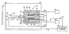
- FIG. 1 is a simplified schematic side view of components of an ink jet printer of an embodiment of the present invention with the drop generator shown in the cross section.
- FIG. 2 is a diagram of the system for circulating the solvent in the ink jet printer in accordance with an embodiment of the present invention.
- FIG. 3 is a cross-sectional view of a drop generator in accordance with an embodiment of the present invention.
- FIG. 1 illustrates a printer that incorporates a cleaning system according to an embodiment of the present invention.
- the printer includes print head 10 having a drop generator 12 , a charge electrode 14 , a ground plate 16 , a high voltage deflection plate 18 , and a catcher 20 .
- the charge electrode 14 , the ground plate 16 , the high voltage deflection plate 18 , and the catcher 20 are positioned between the drop generator 12 and a substrate 21 , which is remotely located from the print head window (not shown).
- the drop generator 12 receives ink from a main conduit 24 as shown and described in U.S. Pat. No. 6,575,556, entitled “Self-Cleaning Print Head for Ink Jet Printer,” which is hereby incorporated by reference in its entirety.
- a piezoelectric cylinder 26 is bonded around the main conduit 24 in order to impart vibrational energy of a selected frequency to the ink received by the drop generator 12 .
- a droplet stream is thus created and selectively charged by the charge electrode 14 .
- An electrostatic field formed between the deflection plate 18 and the ground plate 16 deflects the charged drops of ink over the catcher 20 and onto the substrate 21 . Uncharged drops that pass between the deflection plate 18 and ground plate 16 are not deflected and pass directly into the catcher 20 , which is vacuum assisted to recirculate the ink back into ink reservoir 30 via a return line 31 .
- the drop generator 12 has an outer housing or body 32 with a front face 34 .
- the front face 34 may include a solvent-wettable, generally planar surface as described in the '556 patent.
- the surface is solvent-wettable in order to spread out the solvent to maintain the solvent as a thin film when the viscosity of the solvent is low.
- the solvent-wettable material can be PEEK (polyetheretherketone), for example.
- a solvent-wettable surface is one on which a solvent tends to spread out, whereas a non-solvent wettable surface is one on which a solvent tends to bead up.
- An orifice 36 extends through the front face 34 at an end of the main conduit 24 for emitting the ink stream.
- the drop generator 12 also has a solvent supply conduit 40 with one end terminating at a supply opening 42 on the front face 34 near the orifice 36 .
- the opposite end of the solvent supply conduit 40 is connected to a solvent supply system 44 .
- a flow restrictor (not shown) with a narrow slit or hole may be positioned within the solvent supply conduit 40 for influencing the pressurized solvent to form a thin film at the supply opening 42 by reducing the pressure on the solvent as it flows from supply opening 42 .
- a drain opening 48 communicates with a drain conduit 50 connected to a solvent return system 52 .
- Drain opening 48 may be larger than supply opening 42 .
- the drain conduit 50 under vacuum pressure (for example, approximately 10′′ mercury).
- the solvent 54 flows out of the supply opening 40 , over orifice 36 and into drain opening 48 , is explained in the '556 patent.
- the solvent supply system 44 includes a pump 60 that runs the cleaning solution or solvent from a solvent makeup container 62 , through a conduit 64 and to the supply conduit at the drop generator 12 .
- the conduit 64 is shown with an alternative flow restrictor 66 connected in the solvent supply system 44 .
- the alternative flow restrictor 66 can be used instead of the flow restrictor disposed within the solvent supply conduit 40 in the drop generator 12 .
- the flow restrictor 66 is provided to regulate the flow of solvent through adjustment of the solvent supply pressure.
- a valve 68 such as a solenoid actuated valve, is interconnected between the conduit 64 and the supply conduit 40 for controlling the flow of solvent to the drop generator 12 .
- a valve 70 such as a solenoid activated valve, is interconnected between the conduit 64 and the catcher supply line 71 for controlling the flow of solvent from the solvent supply system 40 to the catcher 20 .
- a single valve could be used to regulate the flow of solvent to both the catcher 20 and drop generator 12 .
- a valve 74 is provided in the solvent supply system 44 for providing compressed air 76 to the pump 60 .
- the pump 60 uses the compressed air 76 to force or push the solvent to the print head 12 and the catcher 20 . It will be appreciated, however, that other pumping systems that do not use compressed air could be used instead.
- the solvent return system 52 has an ink pressure solenoid-activated valve 80 (hereafter, referred to merely as ink pressure solenoid 80 ) connected through conduit 82 to an ink pressure regulator 84 , which in turn is connected to an ink pressure tank 86 though conduit 88 .
- Ink pressure tank 86 is further connected to main conduit 24 through conduit 90 .
- Solenoid 80 also connects with a valve 92 through conduit 94 . In one direction, the valve 92 also connects to a conduit 96 that links to drain conduit 50 at the drop generator 12 . In another direction, the valve 92 connects to a conduit 98 that opens to the ink reservoir 30 .
- ink when the ink jet printer is running, ink is pumped from the reservoir 30 by transfer pump 100 , pressurized in ink pressure tank 86 and then supplied to main conduit 24 via conduit 90 for printing.
- the ink is pressurized by energizing the ink pressure solenoid 80 , which allows compressed air into conduit 82 , ink pressure regulator 84 , conduit 88 and the ink pressure tank 86 .
- Compressed air in the conduit 94 closes air operated valve 92 , which closes off conduit 96 from the ink reservoir vacuum conduit 96 .
- the ink supplied to the main conduit 24 is shut off by de-energizing the ink pressure solenoid 80 to de-pressurize the ink pressure tank 86 , which turns off the ink stream.
- De-energizing solenoid 80 also allows valve 92 to open and connects conduit 50 to the ink reservoir 30 (under vacuum) through conduit 96 . This permits used solvent and residue ink from the front face 34 of the drop generator 12 to be placed in the ink reservoir 30 .
- the solvent that is supplied to the catcher 20 during cleaning is suctioned through the return line 31 and into the reservoir 30 .
- ink composition control is substantially unaffected by the cleaning operation.
- valve 74 Shortly after ink pressure solenoid 80 is de-energized, valve 74 is energized. This allows compressed air 76 to flow through conduit 78 to air operated pump 60 .
- the valves 68 , 70 are selectively opened to regulate the flow of solvent from the pump 60 to the drop generator 12 and the catcher 20 .
- the conduit 64 can include a check valve 102 to prevent reverse or back flow.
- the solvent supply system 44 supplies solvent under pressure through solvent supply conduit 40 in the drop generator 12 and onto front face 34 . On the front face 34 , the solvent spreads over an area adjacent orifice 36 .
- the solvent flow may be uniform or pulsating.
- the type of solvent flow will depend on its supply pressure mechanism. For example, different pump restrictions or pump control systems can provide either uniform or pulsed fluid pressures, thus providing either uniform or pulsating solvent flow.
- the drop generator 12 may also provide with a vacuum conduit 110 that is connected at one end to the main conduit 24 just behind the orifice 36 .
- the other end of the vacuum conduit 110 is connected via conduit 112 to the ink reservoir 30 under vacuum.
- conduit 110 is applying negative pressure or vacuum
- part of the solvent flowing over the orifice 36 is drawn through the orifice 36 in the reverse of the direction of ink flow during printing.
- the solvent is then drawn into main conduit 24 and vacuum conduit 110 , and finally returned to the ink reservoir 30 via conduit 112 .
- This portion of solvent flow effectively cleans the interior of the orifice 36 as well as adjacent parts of the main conduit 24 .
- the remainder of the solvent on the front face 34 flows as described above into drain conduit 50 . Pulsating flow may be used to aid in dissolving residue in the interior of orifice 36 .
- An elastomeric check valve 114 is provided in the conduit 110 .
- the valve 114 opens to allow the flow of solvent in a direction from the orifice 36 to the reservoir 30 and closes to prevent fluid flow in the reverse direction.
- the check valve is preferably in the form of a duck bill valve and may be made of an elastomeric material such as rubber.
- the valve 114 also provides dampening to the ink flow during start up and shut down.
- the dampening provided by the valve 114 is beneficial for reducing ink splatter during start up and shut down. Specifically, at start up there is a quick increase in pressure, which causes a jittering flow effect. This can cause the ink to splatter during start up.
- ink splatters settle on the parts of the print head, solidify, and accumulate over time. These accumulations of ink can obstruct or interfere with the ink jet. Similarly, ink splatter can occur during shut down because the ink pressure does not immediately drop to zero. As the ink jet looses pressure it can break down, resulting in ink splatters.
- the elastomeric duck bill valve dampens the ink flow during start up and shut down, thereby reducing the tendency for ink splatter to occur.
- the ratio of flow through conduits 50 , 110 depends on the amount of vacuum in those conduits and on the geometric dimensions of those conduits.
- the relatively small diameter of orifice 36 which may be on the order of 66 micron, causes a comparatively small amount of flow to be drawn into conduit 110 ; a majority of the solvent flows across the face 34 , around the orifice 36 and into drain opening 48 .
- the flow ratio can be adjusted by varying the amount of vacuum in one or both of the conduits 50 , 110 .
- the ratio can be optimized by changing the vacuum amounts in one or in both of those lines.
- the piezoelectric element 26 is operated during the cleaning process.
- the piezoelectric element 26 generates stress waves, which assist the cleaning process.
- the stress waves loosen particles, facilitating their removal by the makeup flow.
- the voltage and frequency applied to the piezoelectric element 26 can be the same as those used during printing. For example, 30–75 V and 66 KHz. Alternatively, a frequency sweep 30–90 KHz might be applied for more efficient cleaning.
- the design and location of the piezoelectric element in the nozzle contribute to creating effective stress waves.
- the piezoelectric element 26 In order to generate desirable stress waves, the piezoelectric element 26 , as well as the feature it is bonded to, should have cylindrical forms.
- the piezoelectric element 26 is a ceramic tube plated with metal wherein, the outer portion has a negative charge and inner portion has a positive charge.
- Positive and negative lead wires 140 , 142 are connected to the positively and negatively charged portions 144 , 146 of the piezoelectric element 26 . It is difficult to attach the positive lead wire 142 to the positively charged inner portion without breaking cylindrical form of the piezo tube or the feature it is attached to. Therefore, the positive portion 144 is expanded so that it covers a small portion of the outside of the tube (designated as 144 a ) in order to provide a connection point for the positive lead wire 140 .
- This design allows both lead wires 140 , 142 to be attached to the outside of the piezoelectric element 26 .
- the piezoelectric element 26 is constructed such that the negative portion of the outer diameter area remains at least
- the distance from the piezoelectric element 26 to the orifice preferably equals less than 1.1 OD. Moreover, the conductive portion/end of the OD is preferably directed towards the orifice 36 . These parameters have been found to provide effective cleaning.
- Clean start up is also provided by certain sequencing and timing. Specifically after ink is allowed into the drop generator 12 via the conduit 24 , the cavity 120 remains connected with the vacuum for a period of time necessary to fill the cavity 120 with ink. This ensures that no air is left inside the print head 12 . Eliminating air from the print head is beneficial because such air would otherwise be drawn into the ink flow during printing, thereby creating voids in the flow and interrupting normal printer operation.
- conduit 24 which delivers ink to the orifice 36 , is straight, which as been found to be effective in reducing ink splatters during start up and shut down.
- Bypass conduit 110 includes a first portion 118 , which connects to main conduit 24 at a right angle for ease of manufacture.
- This ratio has been found to be effective for both ink jetting and cleaning.
- the elastomeric valve 114 accommodates pressure fluctuations, and prevents ink splatters during shut down and start up. Preventing even small splatters is important because such splatters settle on ground or deflection plates. Over time such ink splatter builds up and can obstruct ink jet and therefore interrupt normal printing process.
- the body 32 of the drop generator may comprise mating first and second portions 150 , 152 .
- the tubular piezoelectric element 26 is mounted over a tubular member 154 formed on the interior of the first portion 152 .
- the tubular member 154 defines the main conduit 24 .
- the check valve 114 mounted within the compartment 120 and is sandwiched between the first and second portions 150 , 152 .
Abstract
A cleaning system for a continuous ink jet printer includes a first solvent supply conduit connected to a solvent source for conveying solvent through a supply opening and onto the front face of the print head. A second solvent supply conduit is connected to the solvent source for conveying solvent through a supply opening and onto a surface of the catcher. The solvent that is supplied to the print head and the catcher is removed under vacuum and returned to the ink supply system. The cleaning system may include an orifice unclogging mechanism that causes said solvent disposed on said front face to flow into said orifice in the reverse of the direction ink flows through said orifice for printing. The cleaning system may also include a piezoelectric element for generating a stress wave in the print head during cleaning. The piezoelectric element may comprise a piezoelectric oscillator that is also used during printing to creates perturbations in the ink flow at the nozzle so as to generate a stream of spaced drops from the nozzle.
Description
This application is a continuation-in-part of application Ser. No. 10/802,256, filed Mar. 17, 2004 and entitled “Ink Jet Print Head Cleaning System,” the entire disclosure of which is hereby incorporated by reference.
Embodiments of the present invention generally relate to a print head for an ink jet printer, and more particularly to an ink jet printer having a system for cleaning the nozzle and the catcher.
Conventional continuous ink jet printers supply electrically conductive ink under pressure to a drop generator, which has an orifice or orifices (nozzles) that are typically arranged in a linear array. The ink discharges from each orifice in the form of a filament, which subsequently breaks up into a droplet stream. Individual droplets in the stream are selectively charged in the region of the break off from the filament, and these charged drops are then deflected as desired by an electrostatic field. The deflected drops may proceed to a print receiving medium, whereas undeflected drops are caught in a gutter or catcher and recirculated.
After the printer is shut down for a period of time, ink around the orifices dries up, often partially blocking, and sometimes completely clogging, the outer openings to the orifices. Furthermore, during a long shut down period, such as an entire day or weekend, the dried ink may form a block within the orifice or passages attached to the orifice, depending on the type of ink.
Typically, print head cleaning systems and methods are limited to the nozzle, or drop generator. However, ink deposits and residue also accumulate around the catcher, for example. Ink droplets often settle on and within the catcher. As ink deposits and residue accumulate on these components, printing quality suffers due to the clogging of the components and conduits therebetween, or due to interference between built-up residue and ink droplets. That is, the recycling rate of ink and other fluids through these components decreases as the accumulation of deposits and residue increases. Often, the ink jet printer is completely shut down in order for an operator to manually clean these components, thereby precluding use of the printer.
Thus, a need exists for a system and method for more effectively cleaning various components of a print head of an ink jet printer. Overall, a need exists for an efficient system and method of cleaning a print head of an ink jet printer.
According to an embodiment of the present invention, a cleaning system is provided for a continuous ink jet printer. The printer has an ink flow system wherein ink flows from a reservoir to a print head. The ink is ejected from the print head in a series of discrete droplets directed at a substrate upon which an image is to be formed by applying droplets to the surface of the substrate. Droplets which are not to be applied to the substrate are collected in a catcher and recycled via a return line to the ink flow system for reuse. The print head includes a front face and at least one orifice extending through the front face. The cleaning system a first solvent supply conduit connected to a solvent source for conveying solvent through a supply opening and onto the front face of the print head. A second solvent supply conduit is connected to the solvent source for conveying solvent through a supply opening and onto a surface of the catcher.
The cleaning system may include an orifice unclogging mechanism that causes said solvent disposed on said front face to flow into said orifice in the reverse of the direction ink flows through said orifice for printing. According to one embodiment, the printer further includes a main conduit for supplying ink to said orifice and the orifice unclogging mechanism includes a vacuum conduit connected to the main conduit so that negative pressure may be applied to suction solvent from the front face, through the orifice and into the vacuum conduit. A check valve may be disposed in the vacuum conduit, the check valve being adapted to open to allow solvent to be suctioned through said vacuum conduit in a first direction and to close to prevent backflow through said conduit in the opposite direction. The check valve is preferably made as rubber duck-bill valve, which has been found to prevent or minimize the mini spills that occur at start up and shut down.
The cleaning system may also include a piezoelectric element for generating a stress wave in the print head during cleaning. The piezoelectric element may comprise a piezoelectric oscillator that is also used during printing to creates perturbations in the ink flow at the nozzle so as to generate a stream of spaced drops from the nozzle.
Another embodiment relates to a method of cleaning a continuous ink jet printer of the type having an ink flow system in which ink is adapted to flow from a reservoir to a print head from which the ink is ejected in a series of discrete droplets directed at a substrate upon which an image is to be formed by applying droplets to the surface of the substrate and in which droplets which are not to be applied to the substrate are collected in a catcher and recycled via a return line to the ink flow system for reuse, the print head having front face and at least one orifice extending through the front face, the orifice defining a nozzle for ejecting the ink. The cleaning method comprises flowing solvent through a solvent supply conduit to a front face of the print head such that the solvent moves along the front face adjacent to the orifice, suctioning the solvent from the front face and into a drain conduit to remove said solvent from the front face of the print head, flowing solvent directly onto a surface of the catcher, and suctioning the solvent from the catcher through the return line. The method may also include the step of flowing the solvent disposed on the front face of the print head into the orifice in the reverse of the direction ink flows through the orifice for printing. The method may also include generating a stress wave in the print head during cleaning so as to loosen dried ink in the print head.
Another embodiment relates to a method of cleaning a continuous ink jet printer of the type having print head with a front face presenting an orifice for emitting a droplet stream toward a substrate during a printing cycle. The cleaning method comprising the steps of supplying solvent to a front face of the print head such that the solvent moves along said front face adjacent to said orifice; and generating a stress wave in the print head during the cleaning process so as to loosen dried ink in the print head.
Another embodiment relates to a cleaning system for a continuous ink jet printer having a print head including a front face and at least one orifice extending through the front face. The cleaning system comprises a conduit for supplying solvent to the front face of the print head, adjacent the orifice. A main ink conduit is provided for supplying ink to the orifice. A vacuum conduit is connected to the main conduit so that negative pressure may be applied to suction solvent from the front face, through the orifice and into the vacuum conduit. A check valve is disposed in the vacuum conduit. The check valve is adapted to open to allow solvent to be suctioned through the vacuum conduit in a first direction and to close to prevent backflow through the conduit in the opposite direction.
The foregoing summary, as well as the following detailed description of certain embodiments of the present invention, will be better understood when read in conjunction with the appended drawings. For the purpose of illustrating the invention, there is shown in the drawings, certain embodiments. It should be understood, however, that the present invention is not limited to the arrangements and instrumentalities shown in the attached drawings.
The drop generator 12 has an outer housing or body 32 with a front face 34. The front face 34 may include a solvent-wettable, generally planar surface as described in the '556 patent. The surface is solvent-wettable in order to spread out the solvent to maintain the solvent as a thin film when the viscosity of the solvent is low. The solvent-wettable material can be PEEK (polyetheretherketone), for example. For purposes of this application, a solvent-wettable surface is one on which a solvent tends to spread out, whereas a non-solvent wettable surface is one on which a solvent tends to bead up.
An orifice 36 extends through the front face 34 at an end of the main conduit 24 for emitting the ink stream. The drop generator 12 also has a solvent supply conduit 40 with one end terminating at a supply opening 42 on the front face 34 near the orifice 36. The opposite end of the solvent supply conduit 40 is connected to a solvent supply system 44. As described in the '556 patent, a flow restrictor (not shown) with a narrow slit or hole may be positioned within the solvent supply conduit 40 for influencing the pressurized solvent to form a thin film at the supply opening 42 by reducing the pressure on the solvent as it flows from supply opening 42.
On the opposite side of the orifice 36 from the position of the solvent supply opening 42, a drain opening 48 communicates with a drain conduit 50 connected to a solvent return system 52. Drain opening 48 may be larger than supply opening 42. The drain conduit 50 under vacuum pressure (for example, approximately 10″ mercury). The solvent 54 flows out of the supply opening 40, over orifice 36 and into drain opening 48, is explained in the '556 patent.
Referring to FIG. 2 , the solvent supply system 44 includes a pump 60 that runs the cleaning solution or solvent from a solvent makeup container 62, through a conduit 64 and to the supply conduit at the drop generator 12. The conduit 64 is shown with an alternative flow restrictor 66 connected in the solvent supply system 44. The alternative flow restrictor 66 can be used instead of the flow restrictor disposed within the solvent supply conduit 40 in the drop generator 12. The flow restrictor 66 is provided to regulate the flow of solvent through adjustment of the solvent supply pressure. A valve 68, such as a solenoid actuated valve, is interconnected between the conduit 64 and the supply conduit 40 for controlling the flow of solvent to the drop generator 12. Similarly, a valve 70, such as a solenoid activated valve, is interconnected between the conduit 64 and the catcher supply line 71 for controlling the flow of solvent from the solvent supply system 40 to the catcher 20. Alternatively, a single valve could be used to regulate the flow of solvent to both the catcher 20 and drop generator 12.
A valve 74 is provided in the solvent supply system 44 for providing compressed air 76 to the pump 60. The pump 60 uses the compressed air 76 to force or push the solvent to the print head 12 and the catcher 20. It will be appreciated, however, that other pumping systems that do not use compressed air could be used instead.
The solvent return system 52 has an ink pressure solenoid-activated valve 80 (hereafter, referred to merely as ink pressure solenoid 80) connected through conduit 82 to an ink pressure regulator 84, which in turn is connected to an ink pressure tank 86 though conduit 88. Ink pressure tank 86 is further connected to main conduit 24 through conduit 90. Solenoid 80 also connects with a valve 92 through conduit 94. In one direction, the valve 92 also connects to a conduit 96 that links to drain conduit 50 at the drop generator 12. In another direction, the valve 92 connects to a conduit 98 that opens to the ink reservoir 30.
Referring to FIGS. 1 and 2 , when the ink jet printer is running, ink is pumped from the reservoir 30 by transfer pump 100, pressurized in ink pressure tank 86 and then supplied to main conduit 24 via conduit 90 for printing. The ink is pressurized by energizing the ink pressure solenoid 80, which allows compressed air into conduit 82, ink pressure regulator 84, conduit 88 and the ink pressure tank 86. Compressed air in the conduit 94 closes air operated valve 92, which closes off conduit 96 from the ink reservoir vacuum conduit 96.
For the cleaning process (preferably before start-up, after shut down and/or during maintenance operations), the ink supplied to the main conduit 24 is shut off by de-energizing the ink pressure solenoid 80 to de-pressurize the ink pressure tank 86, which turns off the ink stream. De-energizing solenoid 80 also allows valve 92 to open and connects conduit 50 to the ink reservoir 30 (under vacuum) through conduit 96. This permits used solvent and residue ink from the front face 34 of the drop generator 12 to be placed in the ink reservoir 30. Similarly, the solvent that is supplied to the catcher 20 during cleaning is suctioned through the return line 31 and into the reservoir 30. As the total amount of solvent added to the ink system during cleaning is relatively small, ink composition control is substantially unaffected by the cleaning operation.
Shortly after ink pressure solenoid 80 is de-energized, valve 74 is energized. This allows compressed air 76 to flow through conduit 78 to air operated pump 60. The valves 68, 70 are selectively opened to regulate the flow of solvent from the pump 60 to the drop generator 12 and the catcher 20. The conduit 64 can include a check valve 102 to prevent reverse or back flow. From conduit 64, the solvent supply system 44 supplies solvent under pressure through solvent supply conduit 40 in the drop generator 12 and onto front face 34. On the front face 34, the solvent spreads over an area adjacent orifice 36. The solvent flow may be uniform or pulsating. The type of solvent flow will depend on its supply pressure mechanism. For example, different pump restrictions or pump control systems can provide either uniform or pulsed fluid pressures, thus providing either uniform or pulsating solvent flow.
While the flow of solvent dissolves residue, ink accumulations or any other particles on the front face 34 and in the orifice 36, the solvent is sucked into drain opening 48 and follows drain conduit 50 back to the solvent return system 52. As described in the '556 patent, appropriate negative pressure or vacuum from drain conduit 50 sustains the solvent flow on the front face 14 in any print head spatial orientation, independent of gravity, and prevents solvent from dropping off the print head 12. After a predetermined cleaning time, valve 74 is de-energized to stop the flow of compressed air 76 and turn off pump 60, thereby stopping the flow of solvent.
Referring again to FIG. 1 , the drop generator 12 may also provide with a vacuum conduit 110 that is connected at one end to the main conduit 24 just behind the orifice 36. The other end of the vacuum conduit 110 is connected via conduit 112 to the ink reservoir 30 under vacuum. During the cleaning process, when conduit 110 is applying negative pressure or vacuum, part of the solvent flowing over the orifice 36 is drawn through the orifice 36 in the reverse of the direction of ink flow during printing. The solvent is then drawn into main conduit 24 and vacuum conduit 110, and finally returned to the ink reservoir 30 via conduit 112. This portion of solvent flow effectively cleans the interior of the orifice 36 as well as adjacent parts of the main conduit 24. The remainder of the solvent on the front face 34 flows as described above into drain conduit 50. Pulsating flow may be used to aid in dissolving residue in the interior of orifice 36.
An elastomeric check valve 114 is provided in the conduit 110. The valve 114 opens to allow the flow of solvent in a direction from the orifice 36 to the reservoir 30 and closes to prevent fluid flow in the reverse direction. The check valve is preferably in the form of a duck bill valve and may be made of an elastomeric material such as rubber. In addition to preventing back flow at the end of the cleaning process, the valve 114 also provides dampening to the ink flow during start up and shut down. The dampening provided by the valve 114 is beneficial for reducing ink splatter during start up and shut down. Specifically, at start up there is a quick increase in pressure, which causes a jittering flow effect. This can cause the ink to splatter during start up. The ink splatters settle on the parts of the print head, solidify, and accumulate over time. These accumulations of ink can obstruct or interfere with the ink jet. Similarly, ink splatter can occur during shut down because the ink pressure does not immediately drop to zero. As the ink jet looses pressure it can break down, resulting in ink splatters. The elastomeric duck bill valve dampens the ink flow during start up and shut down, thereby reducing the tendency for ink splatter to occur.
During the cleaning procedure described above the flow of solvent output from supply opening 42 is divided between the conduits 50, 110. The ratio of flow through conduits 50, 110 depends on the amount of vacuum in those conduits and on the geometric dimensions of those conduits. For example, the relatively small diameter of orifice 36, which may be on the order of 66 micron, causes a comparatively small amount of flow to be drawn into conduit 110; a majority of the solvent flows across the face 34, around the orifice 36 and into drain opening 48. As will be appreciated, the flow ratio can be adjusted by varying the amount of vacuum in one or both of the conduits 50, 110. The ratio can be optimized by changing the vacuum amounts in one or in both of those lines.
According to certain aspects of one embodiment, the piezoelectric element 26 is operated during the cleaning process. The piezoelectric element 26 generates stress waves, which assist the cleaning process. The stress waves loosen particles, facilitating their removal by the makeup flow. The voltage and frequency applied to the piezoelectric element 26 can be the same as those used during printing. For example, 30–75 V and 66 KHz. Alternatively, a frequency sweep 30–90 KHz might be applied for more efficient cleaning.
Referring to FIG. 3 , the design and location of the piezoelectric element in the nozzle, contribute to creating effective stress waves. According to one presently preferred embodiment, the ratio between the parameters of the piezoelectric elements 26 are Lt:OD:ID=2.0:1.4:1.
Where:
-
- Lt is piezoelectric tube length
- OD is tube outside diameter
- ID is tube inside diameter
In order to generate desirable stress waves, the piezoelectric element 26, as well as the feature it is bonded to, should have cylindrical forms. The piezoelectric element 26 is a ceramic tube plated with metal wherein, the outer portion has a negative charge and inner portion has a positive charge. Positive and negative lead wires 140, 142 are connected to the positively and negatively charged portions 144, 146 of the piezoelectric element 26. It is difficult to attach the positive lead wire 142 to the positively charged inner portion without breaking cylindrical form of the piezo tube or the feature it is attached to. Therefore, the positive portion 144 is expanded so that it covers a small portion of the outside of the tube (designated as 144 a) in order to provide a connection point for the positive lead wire 140. This design allows both lead wires 140, 142 to be attached to the outside of the piezoelectric element 26. Preferably the piezoelectric element 26 is constructed such that the negative portion of the outer diameter area remains at least 66% of the entire outer diameter area.
The distance from the piezoelectric element 26 to the orifice preferably equals less than 1.1 OD. Moreover, the conductive portion/end of the OD is preferably directed towards the orifice 36. These parameters have been found to provide effective cleaning.
Clean start up is also provided by certain sequencing and timing. Specifically after ink is allowed into the drop generator 12 via the conduit 24, the cavity 120 remains connected with the vacuum for a period of time necessary to fill the cavity 120 with ink. This ensures that no air is left inside the print head 12. Eliminating air from the print head is beneficial because such air would otherwise be drawn into the ink flow during printing, thereby creating voids in the flow and interrupting normal printer operation.
The design of the drop generator 12 also contributes to clean printer start up. Specifically, conduit 24, which delivers ink to the orifice 36, is straight, which as been found to be effective in reducing ink splatters during start up and shut down. Bypass conduit 110 includes a first portion 118, which connects to main conduit 24 at a right angle for ease of manufacture. According to one presently preferred embodiment, the conduits 24, 118 were configured as:
L/d=2.3
d=dc
L/d=2.3
d=dc
Where:
-
- L is the distance from the orifice to the interconnection between
conduits - d is the diameter of the
conduit 24; and - and dc is the diameter of
conduit 110.
- L is the distance from the orifice to the interconnection between
This ratio has been found to be effective for both ink jetting and cleaning.
As was discussed above, backflow from the cavity 120 is prevented by the check valve 114. The elastomeric valve 114 accommodates pressure fluctuations, and prevents ink splatters during shut down and start up. Preventing even small splatters is important because such splatters settle on ground or deflection plates. Over time such ink splatter builds up and can obstruct ink jet and therefore interrupt normal printing process.
As is shown in FIG. 3 , the body 32 of the drop generator may comprise mating first and second portions 150, 152. The tubular piezoelectric element 26 is mounted over a tubular member 154 formed on the interior of the first portion 152. The tubular member 154 defines the main conduit 24. The check valve 114 mounted within the compartment 120 and is sandwiched between the first and second portions 150, 152.
While the invention has been described with reference to certain embodiments, it will be understood by those skilled in the art that various changes may be made and equivalents may be substituted without departing from the scope of the invention. In addition, many modifications may be made to adapt a particular situation or material to the teachings of the invention without departing from its scope. Therefore, it is intended that the invention not be limited to the particular embodiment disclosed, but that the invention will include all embodiments falling within the scope of the appended claims.
Claims (22)
1. A cleaning system for a continuous ink jet printer of the type having an ink flow system in which ink is adapted to flow from a reservoir to a print head from which the ink is ejected in a series of discrete droplets directed at a substrate upon which an image is to be formed by applying droplets to the surface of the substrate and in which droplets which are not to be applied to the substrate are collected in a catcher and recycled via a return line to the ink flow system for reuse, the print head including a front face and at least one orifice extending through the front face, the orifice defining a nozzle for ejecting the ink, the cleaning system comprising:
a source of solvent;
a first solvent supply conduit connected to the solvent source for conveying solvent through a supply opening and onto the front face of the print head; and
a second solvent supply conduit connected to the solvent source for conveying solvent through a supply opening and onto a surface of the catcher.
2. A cleaning system as set forth in claim 1 , further comprising an orifice unclogging mechanism that causes said solvent disposed on said front face to flow into said orifice in the reverse of the direction ink flows through said orifice for printing.
3. A cleaning system as set forth in claim 2 , wherein the printer further comprise a main conduit for supplying ink to said orifice, and wherein the orifice unclogging mechanism further includes a vacuum conduit connected to the main conduit so that negative pressure may be applied to suction solvent from the front face, through the orifice and into the vacuum conduit.
4. A cleaning system as set forth in claim 3 , further comprising a check valve disposed in said vacuum conduit, the check valve being adapted to open to allow solvent to be suctioned through said vacuum conduit in a first direction and to close to prevent backflow through said conduit in the opposite direction.
5. A cleaning system as set forth in claim 4 , wherein the check valve comprises an elastomeric member.
6. A cleaning system as set forth in claim 1 , further comprising a piezoelectric element for generating a stress wave in the print head during cleaning.
7. A cleaning system as set forth in claim 6 , wherein the piezoelectric element comprises a piezoelectric oscillator that is also used during printing to creates perturbations in the ink flow at the nozzle so as to generate a stream of spaced drops from the nozzle.
8. A cleaning systems as set forth in claim 1 , further comprising a drain conduit for suctioning solvent from the front face of the print head.
9. A method of cleaning a continuous ink jet printer of the type having an ink flow system in which ink is adapted to flow from a reservoir to a print head from which the ink is ejected in a series of discrete droplets directed at a substrate upon which an image is to be formed by applying droplets to the surface of the substrate and in which droplets which are not to be applied to the substrate are collected in a catcher and recycled via a return line to the ink flow system for reuse, the print head having front face and at least one orifice extending through the front face, the cleaning method comprising the steps of:
flowing solvent through a first solvent supply conduit to a front face of the print head such that the solvent moves along said front face adjacent to said orifice;
suctioning the solvent from the front face and into a drain conduit to remove said solvent from the front face of the print head;
flowing solvent through a second solvent supply conduit directly onto a surface of the catcher; and
suctioning the solvent from the catcher through the return line.
10. The method of claim 9 , further comprising the step of flowing the solvent disposed on the front face of the print head into the orifice in the reverse of the direction ink flows through the orifice for printing.
11. The method of claim 9 , further comprising generating a stress wave in the print head during the cleaning process.
12. The method of claim 9 , further comprising operating a piezoelectric element of the print head during cleaning.
13. A method of cleaning a continuous ink jet printer of the type having print head with a front face presenting an orifice for emitting a droplet stream toward a substrate during a printing cycle, the cleaning method comprising the steps of:
supplying solvent to a front face of the print head through a first solvent supply conduit such that the solvent moves along said front face adjacent to said orifice;
flowing solvent directly onto a surface of the catcher through a second solvent supply conduit; and
generating a stress wave in the print head during the cleaning process so as to loosen dried ink in the print head.
14. The method of claim 13 , wherein the step of generating a stress wave comprising operating a piezoelectric element of the print head during cleaning.
15. The method of claim 13 , further comprising
suctioning the solvent from the catcher through a return line.
16. The method of claim 13 , further comprising the step of flowing the solvent disposed on the front face of the print head into the orifice in the reverse of the direction ink flows through the orifice for printing.
17. A self-cleaning print head for an ink jet printer that directs ink to a substrate to be marked, the print head comprising:
a drop generator having front face including an orifice for emitting a droplet stream toward a substrate during a printing cycle;
a charge electrode for selectively charging ink droplets in said droplet stream during the printing cycle;
a deflection plate and a ground plate having a channel formed therein, wherein an electrostatic field is formed between said deflection plate and said ground plate to deflect charged droplets of ink toward the substrate during the printing cycle;
a catcher for receiving uncharged droplets of ink during the printing cycle; and
a solvent supply system that supplies solvent directly to the front face of the drop generator through a first solvent supply conduit and to the catcher through a second solvent supply conduit during a cleaning cycle.
18. A self-cleaning print head for an ink jet printer that directs ink to a substrate to be marked, the print head comprising:
a drop generator having an orifice for emitting a droplet stream toward a substrate during a printing cycle, the drop generator including a piezoelectric element that is operable during a cleaning cycle for generating a stress wave in the drop generator and that is operable during a printing cycle to create perturbations in the ink flow at the orifice so as to generate a stream of spaced drops from the orifice;
a solvent supply system that supplies solvent to the drop generator through a first solvent supply conduit to clean at least a portion of the drop generator during the cleaning process, said solvent supply system also supplying solvent to a catcher through a second solvent supply conduit, said solvent being formulated to remove ink residue from said drop generator as said solvent flows over said drop generator.
19. A print head as set forth in claim 18 , wherein said solvent supply system supplies solvent to an exterior surface of the drop generator adjacent to the orifice.
20. A print head as set forth in claim 18 , wherein the print head further comprises a catcher for catching uncharged ink drops during the printing cycle and wherein the solvent supply system further supplies solvent directly to a surface of said catcher during the cleaning process.
21. A cleaning system for a continuous ink jet printer having a print head including a front face and at least one orifice extending through the front face, the cleaning system comprising:
a conduit for supplying solvent to the front face of the print head, adjacent the orifice;
a main ink conduit for supplying ink to said orifice;
a vacuum conduit connected to the main conduit so that negative pressure may be applied to suction solvent from the front face, through the orifice and into the vacuum conduit; and
a check valve disposed in said vacuum conduit, the check valve being adapted to open to allow solvent to be suctioned through said vacuum conduit in a first direction and to close to prevent backflow through said conduit in the opposite direction.
22. The cleaning system of claim 21 , wherein the check valve comprises an elastomeric check valve.
Priority Applications (7)
| Application Number | Priority Date | Filing Date | Title |
|---|---|---|---|
| US10/871,642 US7150512B2 (en) | 2004-03-17 | 2004-06-17 | Cleaning system for a continuous ink jet printer |
| KR1020067021112A KR101127418B1 (en) | 2004-03-17 | 2005-03-15 | Cleaning system for a continuous ink jet printer |
| PCT/EP2005/002750 WO2005090084A1 (en) | 2004-03-17 | 2005-03-15 | Cleaning system for a continuous ink jet printer |
| EP05716080A EP1725408B1 (en) | 2004-03-17 | 2005-03-15 | Cleaning system for a continuous ink jet printer |
| DE602005010217T DE602005010217D1 (en) | 2004-03-17 | 2005-03-15 | CLEANING SYSTEM FOR A CONTINUOUSLY WORKING INK JET PRINTER |
| JP2007503273A JP2007529338A (en) | 2004-03-17 | 2005-03-15 | Cleaning system for continuous inkjet printer |
| HK07111473.6A HK1106191A1 (en) | 2004-03-17 | 2007-10-24 | Cleaning system, self-cleaning print head and cleaning method for a continuous ink jet printer |
Applications Claiming Priority (2)
| Application Number | Priority Date | Filing Date | Title |
|---|---|---|---|
| US10/802,256 US7128410B2 (en) | 2004-03-17 | 2004-03-17 | Ink jet print head cleaning system |
| US10/871,642 US7150512B2 (en) | 2004-03-17 | 2004-06-17 | Cleaning system for a continuous ink jet printer |
Related Parent Applications (1)
| Application Number | Title | Priority Date | Filing Date |
|---|---|---|---|
| US10/802,256 Continuation-In-Part US7128410B2 (en) | 2004-03-17 | 2004-03-17 | Ink jet print head cleaning system |
Publications (2)
| Publication Number | Publication Date |
|---|---|
| US20050206673A1 US20050206673A1 (en) | 2005-09-22 |
| US7150512B2 true US7150512B2 (en) | 2006-12-19 |
Family
ID=34962499
Family Applications (1)
| Application Number | Title | Priority Date | Filing Date |
|---|---|---|---|
| US10/871,642 Active 2024-12-28 US7150512B2 (en) | 2004-03-17 | 2004-06-17 | Cleaning system for a continuous ink jet printer |
Country Status (7)
| Country | Link |
|---|---|
| US (1) | US7150512B2 (en) |
| EP (1) | EP1725408B1 (en) |
| JP (1) | JP2007529338A (en) |
| KR (1) | KR101127418B1 (en) |
| DE (1) | DE602005010217D1 (en) |
| HK (1) | HK1106191A1 (en) |
| WO (1) | WO2005090084A1 (en) |
Cited By (5)
| Publication number | Priority date | Publication date | Assignee | Title |
|---|---|---|---|---|
| US20080218552A1 (en) * | 2007-03-06 | 2008-09-11 | Jinquan Xu | Printing system particle removal device and method |
| US20090021567A1 (en) * | 2007-07-20 | 2009-01-22 | Zhanjun Gao | Printing system particle removal device and method |
| US8876252B2 (en) | 2011-05-02 | 2014-11-04 | Illinois Tool Works, Inc. | Solvent flushing for fluid jet device |
| EP3628491A1 (en) * | 2018-09-27 | 2020-04-01 | Hitachi Industrial Equipment Systems Co., Ltd. | Ink jet recording apparatus |
| WO2021130476A1 (en) * | 2019-12-23 | 2021-07-01 | Videojet Technologies Inc. | Method of operating a printhead |
Families Citing this family (14)
| Publication number | Priority date | Publication date | Assignee | Title |
|---|---|---|---|---|
| FR2937584B1 (en) * | 2008-10-28 | 2010-12-24 | Imaje Sa | PRINTER WITH A CONTINUOUS JET PRINTING HEAD AND DEVICE FOR CLEANING THE HEAD |
| FR2955801B1 (en) | 2010-02-01 | 2012-04-13 | Markem Imaje | DEVICE FORMING A CONTINUOUS INK JET PRINTER WITH SOLVENT VAPOR CONCENTRATIONS INSIDE AND AROUND THE DECREASED PUPITRE |
| WO2011100517A1 (en) * | 2010-02-13 | 2011-08-18 | Videojet Technologies Inc. | Printer cleaning method |
| DE102012214349A1 (en) * | 2012-08-13 | 2014-02-13 | Krones Aktiengesellschaft | Printing device, printhead therefor and method for vacuuming ink |
| WO2018143953A1 (en) * | 2017-01-31 | 2018-08-09 | Hewlett-Packard Development Company, L.P. | Printhead cleaning system |
| FR3082778A1 (en) * | 2018-06-21 | 2019-12-27 | Dover Europe Sarl | PRINTHEAD OF AN INK JET PRINTER WITH 2 RECOVERY GUTTERS, INCLUDING A MOBILE |
| FR3082779B1 (en) | 2018-06-21 | 2021-02-12 | Dover Europe Sarl | METHOD AND DEVICE FOR MAINTENANCE OF A PRINTING HEAD BY NOZZLE |
| FR3082777A1 (en) | 2018-06-21 | 2019-12-27 | Dover Europe Sarl | METHOD AND DEVICE FOR DETECTING THE PROPER FUNCTIONING OF NOZZLES OF A PRINTHEAD |
| GB2575986A (en) * | 2018-07-30 | 2020-02-05 | Domino Uk Ltd | Solvent supply tube arrangement |
| JP2020093444A (en) * | 2018-12-12 | 2020-06-18 | 株式会社日立産機システム | Inkjet recording device and cleaning method for inkjet recording device |
| WO2021076126A1 (en) * | 2019-10-16 | 2021-04-22 | Hewlett-Packard Development Company, L.P. | Liquid printing material conduit |
| KR102113433B1 (en) * | 2019-11-14 | 2020-06-02 | 조선영 | Repairing Apparatus for Inkjet Printer |
| KR102113432B1 (en) * | 2019-11-14 | 2020-05-20 | 조선영 | Repairing Apparatus for Inkjet Printer |
| JP6763628B1 (en) * | 2020-04-24 | 2020-09-30 | 紀州技研工業株式会社 | Inkjet printer |
Citations (22)
| Publication number | Priority date | Publication date | Assignee | Title |
|---|---|---|---|---|
| US4528996A (en) | 1983-12-22 | 1985-07-16 | The Mead Corporation | Orifice plate cleaning system |
| US4563688A (en) | 1983-05-16 | 1986-01-07 | Eastman Kodak Company | Fluid jet printer and method of ultrasonic cleaning |
| WO1993017867A1 (en) | 1992-03-12 | 1993-09-16 | Willett International Limited | Method for flushing an ink flow system |
| US5557306A (en) | 1992-12-16 | 1996-09-17 | Seiko Epson Corporation | Ink jet printer with a cleaning apparatus for removing hardened ink from a nozzle plate of a print head |
| US5581282A (en) | 1986-10-31 | 1996-12-03 | Canon Kabushiki Kaisha | Ink jet recording apparatus with two cleaning members |
| US5598197A (en) | 1989-07-11 | 1997-01-28 | Domino Printing Sciences Plc | Continuous ink jet printer |
| WO1998006583A1 (en) | 1996-08-15 | 1998-02-19 | Linx Printing Technologies Plc | Ink jet printer |
| US5877788A (en) | 1995-05-09 | 1999-03-02 | Moore Business Forms, Inc. | Cleaning fluid apparatus and method for continuous printing ink-jet nozzle |
| WO1999062717A1 (en) | 1998-05-29 | 1999-12-09 | Willett International Limited | Ink jet printer and method of operation |
| US6145952A (en) | 1998-10-19 | 2000-11-14 | Eastman Kodak Company | Self-cleaning ink jet printer and method of assembling same |
| US6254216B1 (en) | 1997-07-01 | 2001-07-03 | Marconi Data Systems Inc. | Clean-in place system for an ink jet printhead |
| US6273103B1 (en) * | 1998-12-14 | 2001-08-14 | Scitex Digital Printing, Inc. | Printhead flush and cleaning system and method |
| US20010043250A1 (en) | 1998-11-18 | 2001-11-22 | Faisst Charles F. | Ink jet printer with cleaning mechanism and method of assembling same |
| EP1170130A1 (en) | 2000-06-29 | 2002-01-09 | EASTMAN KODAK COMPANY (a New Jersey corporation) | Method and cleaning assembly for cleaning an ink jet print head in a self-cleaning ink jet printer system |
| US20020075350A1 (en) | 2000-12-15 | 2002-06-20 | Xerox Corporation | Ink jet printer having a cleaning blade cleaner assembly |
| US20020085058A1 (en) | 2000-12-28 | 2002-07-04 | Griffin Todd R. | Ink jet printer with cleaning mechanism using laminated polyimide structure and method cleaning an ink jet printer |
| US20020122090A1 (en) | 2000-12-29 | 2002-09-05 | Ravi Sharma | Self-cleaning ink jet printer and print head with cleaning fluid flow system |
| US20020126174A1 (en) | 2000-12-29 | 2002-09-12 | Ravi Sharma | Self-cleaning printer and print head and method for manufacturing same |
| US6478402B1 (en) | 1999-06-28 | 2002-11-12 | Heidelberger Druckmaschinen Ag | Method and device for cleaning a nozzle outlet surface on a print head of an ink jet printer |
| US20020186270A1 (en) | 2001-05-30 | 2002-12-12 | Eastman Kodak Company | Ink jet print head with cross-flow cleaning |
| US6511151B1 (en) | 1998-12-28 | 2003-01-28 | Eastman Kodak Company | Ink jet printer and cleaning blade and method of cleaning |
| US6575556B1 (en) * | 2000-09-18 | 2003-06-10 | Marconi Data Systems Inc. | Self-cleaning print head for ink jet printer |
Family Cites Families (4)
| Publication number | Priority date | Publication date | Assignee | Title |
|---|---|---|---|---|
| EP0117013A3 (en) * | 1983-01-04 | 1986-11-05 | Sage Technology, Inc. | Additive film and method |
| JPS608044A (en) * | 1983-06-28 | 1985-01-16 | Haruo Suzuki | Fitting method of doubly lapped synthetic resin handle to synthetic resin bag and synthetic resin bag |
| JPH0453753A (en) * | 1990-06-22 | 1992-02-21 | Toppan Printing Co Ltd | Printing head for ink jet printer |
| DE4408540C1 (en) * | 1994-03-14 | 1995-03-23 | Jenoptik Technologie Gmbh | Arrangement for optical autocorrelation |
-
2004
- 2004-06-17 US US10/871,642 patent/US7150512B2/en active Active
-
2005
- 2005-03-15 DE DE602005010217T patent/DE602005010217D1/en active Active
- 2005-03-15 EP EP05716080A patent/EP1725408B1/en active Active
- 2005-03-15 WO PCT/EP2005/002750 patent/WO2005090084A1/en active Application Filing
- 2005-03-15 JP JP2007503273A patent/JP2007529338A/en active Pending
- 2005-03-15 KR KR1020067021112A patent/KR101127418B1/en not_active IP Right Cessation
-
2007
- 2007-10-24 HK HK07111473.6A patent/HK1106191A1/en not_active IP Right Cessation
Patent Citations (30)
| Publication number | Priority date | Publication date | Assignee | Title |
|---|---|---|---|---|
| US4563688A (en) | 1983-05-16 | 1986-01-07 | Eastman Kodak Company | Fluid jet printer and method of ultrasonic cleaning |
| US4528996A (en) | 1983-12-22 | 1985-07-16 | The Mead Corporation | Orifice plate cleaning system |
| US5581282A (en) | 1986-10-31 | 1996-12-03 | Canon Kabushiki Kaisha | Ink jet recording apparatus with two cleaning members |
| US5598197A (en) | 1989-07-11 | 1997-01-28 | Domino Printing Sciences Plc | Continuous ink jet printer |
| WO1993017867A1 (en) | 1992-03-12 | 1993-09-16 | Willett International Limited | Method for flushing an ink flow system |
| US6158839A (en) | 1992-12-16 | 2000-12-12 | Seiko Epson Corporation | Ink jet printer with a cleaning apparatus for removing hardened ink from a nozzle plate of a print head |
| US5557306A (en) | 1992-12-16 | 1996-09-17 | Seiko Epson Corporation | Ink jet printer with a cleaning apparatus for removing hardened ink from a nozzle plate of a print head |
| US5877788A (en) | 1995-05-09 | 1999-03-02 | Moore Business Forms, Inc. | Cleaning fluid apparatus and method for continuous printing ink-jet nozzle |
| WO1998006583A1 (en) | 1996-08-15 | 1998-02-19 | Linx Printing Technologies Plc | Ink jet printer |
| US6254216B1 (en) | 1997-07-01 | 2001-07-03 | Marconi Data Systems Inc. | Clean-in place system for an ink jet printhead |
| WO1999062717A1 (en) | 1998-05-29 | 1999-12-09 | Willett International Limited | Ink jet printer and method of operation |
| US6145952A (en) | 1998-10-19 | 2000-11-14 | Eastman Kodak Company | Self-cleaning ink jet printer and method of assembling same |
| US20010043250A1 (en) | 1998-11-18 | 2001-11-22 | Faisst Charles F. | Ink jet printer with cleaning mechanism and method of assembling same |
| US6435647B2 (en) | 1998-11-18 | 2002-08-20 | Eastman Kodak Company | Ink jet printer with cleaning mechanism and method of assembling same |
| US6347858B1 (en) | 1998-11-18 | 2002-02-19 | Eastman Kodak Company | Ink jet printer with cleaning mechanism and method of assembling same |
| US6273103B1 (en) * | 1998-12-14 | 2001-08-14 | Scitex Digital Printing, Inc. | Printhead flush and cleaning system and method |
| US6511151B1 (en) | 1998-12-28 | 2003-01-28 | Eastman Kodak Company | Ink jet printer and cleaning blade and method of cleaning |
| US6478402B1 (en) | 1999-06-28 | 2002-11-12 | Heidelberger Druckmaschinen Ag | Method and device for cleaning a nozzle outlet surface on a print head of an ink jet printer |
| EP1170130A1 (en) | 2000-06-29 | 2002-01-09 | EASTMAN KODAK COMPANY (a New Jersey corporation) | Method and cleaning assembly for cleaning an ink jet print head in a self-cleaning ink jet printer system |
| US6406122B1 (en) | 2000-06-29 | 2002-06-18 | Eastman Kodak Company | Method and cleaning assembly for cleaning an ink jet print head in a self-cleaning ink jet printer system |
| US6575556B1 (en) * | 2000-09-18 | 2003-06-10 | Marconi Data Systems Inc. | Self-cleaning print head for ink jet printer |
| US20020075350A1 (en) | 2000-12-15 | 2002-06-20 | Xerox Corporation | Ink jet printer having a cleaning blade cleaner assembly |
| US20020085058A1 (en) | 2000-12-28 | 2002-07-04 | Griffin Todd R. | Ink jet printer with cleaning mechanism using laminated polyimide structure and method cleaning an ink jet printer |
| US6523930B2 (en) | 2000-12-28 | 2003-02-25 | Eastman Kodak Company | Ink jet printer with cleaning mechanism using laminated polyimide structure and method cleaning an ink jet printer |
| US20020122090A1 (en) | 2000-12-29 | 2002-09-05 | Ravi Sharma | Self-cleaning ink jet printer and print head with cleaning fluid flow system |
| US20020126174A1 (en) | 2000-12-29 | 2002-09-12 | Ravi Sharma | Self-cleaning printer and print head and method for manufacturing same |
| US6497472B2 (en) | 2000-12-29 | 2002-12-24 | Eastman Kodak Company | Self-cleaning ink jet printer and print head with cleaning fluid flow system |
| US6595617B2 (en) | 2000-12-29 | 2003-07-22 | Eastman Kodak Company | Self-cleaning printer and print head and method for manufacturing same |
| US20020186270A1 (en) | 2001-05-30 | 2002-12-12 | Eastman Kodak Company | Ink jet print head with cross-flow cleaning |
| US6572215B2 (en) | 2001-05-30 | 2003-06-03 | Eastman Kodak Company | Ink jet print head with cross-flow cleaning |
Non-Patent Citations (2)
| Title |
|---|
| "Videojet Excel Series Auto Flush Addendum", PIN 365322-01, Rev. CC 04/02. |
| Aug. 16, 2005 International Search Report and Written Opinion for PCT/EP2005/002750. |
Cited By (11)
| Publication number | Priority date | Publication date | Assignee | Title |
|---|---|---|---|---|
| US20080218552A1 (en) * | 2007-03-06 | 2008-09-11 | Jinquan Xu | Printing system particle removal device and method |
| US7735954B2 (en) | 2007-03-06 | 2010-06-15 | Eastman Kodak Company | Printing system particle removal device and method |
| US20090021567A1 (en) * | 2007-07-20 | 2009-01-22 | Zhanjun Gao | Printing system particle removal device and method |
| US7946683B2 (en) | 2007-07-20 | 2011-05-24 | Eastman Kodak Company | Printing system particle removal device and method |
| US8876252B2 (en) | 2011-05-02 | 2014-11-04 | Illinois Tool Works, Inc. | Solvent flushing for fluid jet device |
| EP3628491A1 (en) * | 2018-09-27 | 2020-04-01 | Hitachi Industrial Equipment Systems Co., Ltd. | Ink jet recording apparatus |
| CN110949010A (en) * | 2018-09-27 | 2020-04-03 | 株式会社日立产机系统 | Ink jet recording apparatus |
| US10933642B2 (en) | 2018-09-27 | 2021-03-02 | Hitachi Industrial Equipment Systems Co., Ltd. | Ink jet recording apparatus |
| US11623444B2 (en) | 2018-09-27 | 2023-04-11 | Hitachi Industrial Equipment Systems Co., Ltd. | Ink jet recording apparatus |
| WO2021130476A1 (en) * | 2019-12-23 | 2021-07-01 | Videojet Technologies Inc. | Method of operating a printhead |
| CN115103774A (en) * | 2019-12-23 | 2022-09-23 | 录象射流技术公司 | Method of operating a printhead |
Also Published As
| Publication number | Publication date |
|---|---|
| KR101127418B1 (en) | 2012-03-23 |
| JP2007529338A (en) | 2007-10-25 |
| EP1725408B1 (en) | 2008-10-08 |
| KR20070002049A (en) | 2007-01-04 |
| US20050206673A1 (en) | 2005-09-22 |
| DE602005010217D1 (en) | 2008-11-20 |
| HK1106191A1 (en) | 2008-03-07 |
| WO2005090084A8 (en) | 2006-09-14 |
| WO2005090084A1 (en) | 2005-09-29 |
| EP1725408A1 (en) | 2006-11-29 |
Similar Documents
| Publication | Publication Date | Title |
|---|---|---|
| EP1725408B1 (en) | Cleaning system for a continuous ink jet printer | |
| CN100478182C (en) | Continuous ink jet printer cleaning system, self-cleaning printing head and cleaning method | |
| US6575556B1 (en) | Self-cleaning print head for ink jet printer | |
| US6802588B2 (en) | Fluid jet apparatus and method for cleaning inkjet printheads | |
| US6174052B1 (en) | Self-priming system for ink jet printers | |
| US7364285B2 (en) | Pressure damping ink filter | |
| WO1993017867A1 (en) | Method for flushing an ink flow system | |
| US11760096B2 (en) | Method and device for maintaining a nozzle print head | |
| JP4350187B2 (en) | Inkjet recording device | |
| JP2004195978A (en) | Starting and ending of continuous inkjet print head | |
| CN101155693A (en) | Method for removing air from ink jet device, and ink jet device | |
| JP2004223829A (en) | Inkjet recorder | |
| JP4832356B2 (en) | Inkjet recording device | |
| JP2000203051A (en) | Ink jet recording apparatus | |
| US8876252B2 (en) | Solvent flushing for fluid jet device | |
| JP3286209B2 (en) | Ink jet recording apparatus and nozzle cleaning method thereof | |
| US9346261B1 (en) | Negative air duct sump for ink removal | |
| JP4241219B2 (en) | On-demand inkjet recording device | |
| JP6345066B2 (en) | Inkjet recording device | |
| JP2024515281A (en) | Continuous Inkjet Printer | |
| JP2004268566A (en) | Device and method to uniformly and equally supply ink to both ends of liquid droplet generator | |
| KR20020049716A (en) | Maintenance structure of ink-jet print-head using ink supply valve | |
| JPS58118264A (en) | Ink jet printer |
Legal Events
| Date | Code | Title | Description |
|---|---|---|---|
| AS | Assignment |
Owner name: VIDEOJET TECHNOLOGIES INC., ILLINOIS Free format text: ASSIGNMENT OF ASSIGNORS INTEREST;ASSIGNORS:LEVIN, ALEXANDER M.;LOSTUMBO, PIETRO;REEL/FRAME:017541/0923 Effective date: 20040628 |
|
| STCF | Information on status: patent grant |
Free format text: PATENTED CASE |
|
| FPAY | Fee payment |
Year of fee payment: 4 |
|
| FPAY | Fee payment |
Year of fee payment: 8 |
|
| MAFP | Maintenance fee payment |
Free format text: PAYMENT OF MAINTENANCE FEE, 12TH YEAR, LARGE ENTITY (ORIGINAL EVENT CODE: M1553) Year of fee payment: 12 |